EP3566521B1 - Information transmission method and apparatus and storage medium - Google Patents
Information transmission method and apparatus and storage medium Download PDFInfo
- Publication number
- EP3566521B1 EP3566521B1 EP18747386.3A EP18747386A EP3566521B1 EP 3566521 B1 EP3566521 B1 EP 3566521B1 EP 18747386 A EP18747386 A EP 18747386A EP 3566521 B1 EP3566521 B1 EP 3566521B1
- Authority
- EP
- European Patent Office
- Prior art keywords
- pucch
- pairs
- antenna
- symbols
- transmitting
- Prior art date
- Legal status (The legal status is an assumption and is not a legal conclusion. Google has not performed a legal analysis and makes no representation as to the accuracy of the status listed.)
- Active
Links
Images


Classifications
-
- H—ELECTRICITY
- H04—ELECTRIC COMMUNICATION TECHNIQUE
- H04W—WIRELESS COMMUNICATION NETWORKS
- H04W72/00—Local resource management
- H04W72/04—Wireless resource allocation
- H04W72/044—Wireless resource allocation based on the type of the allocated resource
- H04W72/0446—Resources in time domain, e.g. slots or frames
-
- H—ELECTRICITY
- H04—ELECTRIC COMMUNICATION TECHNIQUE
- H04W—WIRELESS COMMUNICATION NETWORKS
- H04W72/00—Local resource management
- H04W72/20—Control channels or signalling for resource management
- H04W72/21—Control channels or signalling for resource management in the uplink direction of a wireless link, i.e. towards the network
-
- H—ELECTRICITY
- H04—ELECTRIC COMMUNICATION TECHNIQUE
- H04L—TRANSMISSION OF DIGITAL INFORMATION, e.g. TELEGRAPHIC COMMUNICATION
- H04L5/00—Arrangements affording multiple use of the transmission path
- H04L5/003—Arrangements for allocating sub-channels of the transmission path
- H04L5/0048—Allocation of pilot signals, i.e. of signals known to the receiver
-
- H—ELECTRICITY
- H04—ELECTRIC COMMUNICATION TECHNIQUE
- H04L—TRANSMISSION OF DIGITAL INFORMATION, e.g. TELEGRAPHIC COMMUNICATION
- H04L5/00—Arrangements affording multiple use of the transmission path
- H04L5/0001—Arrangements for dividing the transmission path
- H04L5/0003—Two-dimensional division
- H04L5/0005—Time-frequency
- H04L5/0007—Time-frequency the frequencies being orthogonal, e.g. OFDM(A), DMT
- H04L5/0012—Hopping in multicarrier systems
Definitions
- the present disclosure relates to the technical field of communications, and particularly an information transmission method and apparatus and storage medium.
- Physical Uplink Control Channel is transmitted in a full uplink subframe with fixed number of symbols (e.g., 14 symbols) at the edges of system bandwidth, and is used to carry uplink control information (UCI) such as Ack/NACK for downlink Physical Downlink Shared Channel (PDSCH) transmission and channel state information (CSI) feedback from the User Equipment (UE).
- UCI uplink control information
- PDSCH Physical Downlink Shared Channel
- CSI channel state information
- NTT DOCOMO ET AL "Summary of [87-36]: Mini-slot designs for NR", 3GPP DRAFT; R1-1700617, 3RD GENERATION PARTNERSHIP PROJECT (3GPP), MOBILE COMPETENCE CENTRE; 650, ROUTE DES LUCIOLES; F-06921 SOPHIA-ANTIPOLIS CEDEX; FRANCE, vol. RAN WG1, no.
- An objective of this disclosure is to provide an information transmission method, which is capable of achieving low latency of services.
- the invention is defined by the independent claims.
- the method includes that an RS symbol is placed at beginning of a PUCCH, UCI symbols are placed after the RS symbol in the PUCCH, and the PUCCH is transmitted.
- the PUCCH may be transmitted in one or more slots of a first type, wherein all symbols in each of the slots of the first type are uplink, which are dedicated for transmitting the PUCCH; or the PUCCH may be transmitted in one or more slots of a second type, wherein more than one half of symbols in each of the slots of the second type are uplink, which are dedicated for transmitting the PUCCH; or the PUCCH may be transmitted in multiple slots comprising one or more slots of the first type and one or more slots of the second type.
- the first RS symbol may be transmitted at the beginning of the PUCCH, in each of the slots of the first or second type.
- a second RS symbol may further be placed at end of the PUCCH, in each of the slots of the first or second type; and/or one or more third RS symbols are placed evenly in between the UCI symbols, in the PUCCH in each of the slots of the first or second type.
- one or two RS symbols may be placed immediately after every n contiguous UCI symbols, in each of the slots of the first or second type, until a last symbol in the slot is filled by an RS or UCI symbol, where n is an integer greater than or equal to 1.
- Space-Time Block Coding may be performed on at least a portion of the UCI symbols in the PUCCH to build STBC codes.
- an orthogonal sequence may be generated for each of modulated symbols carrying UCI in the PUCCH, wherein the UCI symbols comprise m UCI symbols in time, where m is an integer, and greater than or equal to 2; the performing STBC on at least a portion of UCI symbols may include: for (2 k -1) th and (2 k ) th UCI symbols in time, the elements of the orthogonal sequences corresponding to the (2 k -1) th and (2 k ) th UCI symbols are directly used to build a first set of pairs of STBC codes, and conjugation transformation on the elements of the generated orthogonal sequences corresponding to the (2 k -1) th and (2 k ) th UCI symbols is performed to build a second set of pairs of STBC codes; the PUCCH with the first set of pairs of STBC codes may be transmitted via a first antenna, and the PUCCH with the second set of pairs of STBC codes may be transmitted via a second antenna, where k is a positive integer and
- Cyclic Delay Diversity CDD
- SORTD Space Orthogonal-Resource Transmit Diversity
- the PUCCH transmitted in a single one of the first or second slots may be divided into a first portion and a second portion; the first portion of the PUCCH may be transmitted in a first frequency band; and the second portion of the PUCCH may be transmitted in a second frequency band.
- the PUCCH may be divided such that the second portion of the PUCCH begins with an RS symbol.
- the apparatus includes a processor; and one or more modules stored on a memory and executable by the processor, the one or more modules include: a placement module, configured to place a first RS symbol at beginning of a Physical Uplink Control Channel (PUCCH), and place UCI symbols after the first RS symbol in the PUCCH; and a transmitter, configured to transmit the PUCCH.
- a placement module configured to place a first RS symbol at beginning of a Physical Uplink Control Channel (PUCCH), and place UCI symbols after the first RS symbol in the PUCCH
- a transmitter configured to transmit the PUCCH.
- the transmitter may be configured to perform one of the following: transmit the PUCCH in one or more slots of a first type, wherein all symbols in each of the slots of the first type are uplink, which are dedicated for transmitting the PUCCH; transmit the PUCCH in one or more slots of a second type, wherein more than one half of symbols in each of the slots of the second type are uplink, which are dedicated for transmitting the PUCCH; and transmit the PUCCH in multiple slots comprising one or more slots of the first type and one or more slots of the second type; and the RS placement module may be configured to place the first RS symbol at the beginning of the PUCCH, in each of the slots of the first or second type.
- the placement module may further be configured to perform at least one of the following: place a second RS symbol at end of the PUCCH, in each of the slots of the first or second type; and place one or more third RS symbols evenly in between the UCI symbols, in the PUCCH in each of the slots of the first or second type.
- the placement module may further be configured to place one or two RS symbols immediately after every n contiguous UCI symbols, in each of the slots of the first or second type, until a last symbol in the slot is filled by an RS or UCI symbol, where n is an integer greater than or equal to 1.
- the one or more modules may further include a transmit diversity module, configured to perform Space-Time Block Coding (STBC) on at least a portion of the UCI symbols in the PUCCH to build STBC codes.
- STBC Space-Time Block Coding
- the one or more modules may further include a sequence generation module configured to generate an orthogonal sequence for each of modulated symbols carrying UCI in the PUCCH, where the UCI symbols comprise m UCI symbols in time, where m is an integer, and greater than or equal to 2;
- the transmit diversity module may be configured to: for (2 k -1) th and (2 k ) th UCI symbols in time, directly use elements of the orthogonal sequences corresponding to the (2 k -1) th and (2 k ) th UCI symbols to build a first set of pairs of STBC codes, and perform conjugation transformation on the elements of the generated orthogonal sequences corresponding to the (2 k -1) th and (2 k ) th UCI symbols to build a second set of pairs of STBC codes;
- the transmitter may be configured to: transmit the PUCCH with the first set of pairs of STBC codes via a first antenna; and transmit the PUCCH with the second set of pairs of STBC codes via a second antenna, where k is
- the transmit diversity module may further be configured to perform Cyclic Delay Diversity (CDD) or Space Orthogonal-Resource Transmit Diversity (SORTD) on a last DCI symbol in time among the m DCI symbols to build CDD or SORTD codes for the last DCI symbol.
- CDD Cyclic Delay Diversity
- SORTD Space Orthogonal-Resource Transmit Diversity
- the transmitter may further be configured to: divide the PUCCH transmitted in a single one of the first or second slots into a first portion and a second portion; transmit the first portion of the PUCCH in a first frequency band; and transmit the second portion of the PUCCH in a second frequency band.
- the PUCCH may be divided such that the second portion of the PUCCH begins with an RS symbol.
- the disclosure also provides a non-transitory computer readable storage radium, having instructions stored therein, which when executed by a processor, causes the processor to execute the method as described above.
- front-loaded RS is used in RS design for PUCCH with long duration, which achieves low latency of services in the 5G TR system.
- Rest RS symbols may be placed with one DMRS symbol for every n UCI symbols, where n is an integer greater than or equal to 1.
- Frequency hopping may also be used for PUCCH with long duration, thus obtaining more frequency diversity gain.
- STBC When STBC is used as transmit diversity of PUCCH with long duration, it would bring superior transmit diversity gain, does not require additional sequence resources, and improve coverage and robustness performances.
- a user equipment which can be a wireless terminal.
- the UE can also be called a system, device, subscriber unit, subscriber station, mobile station, mobile, mobile device, remote station, remote terminal, access terminal, user terminal, terminal, communication device, user agent, or user device.
- the UE may be a cellular telephone, a satellite phone, a cordless telephone, a Session Initiation Protocol (SIP) phone, a wireless local loop (WLL) station, a personal digital assistant (PDA), a handheld device having wireless connection capability, a computing device, or other processing devices connected to a wireless modem.
- SIP Session Initiation Protocol
- WLL wireless local loop
- PDA personal digital assistant
- a base station may be utilized for communicating with wireless terminal(s) and may also be referred to as an access point, a Node B, evolved Node B (eNB), H(e)NB, or some other terminology.
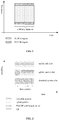
- FIG. 2 illustrates several slot structure examples in the 5G NR system.
- the slot may be classified into uplink only slot, uplink-centric slot and downlink-centric slot.
- the PUCCH with long duration may be transmitted in the middle part of the system bandwidth (shown in FIG. 2 ) or the edges of the system bandwidth (not shown), or the like.
- symbols for both UL transmission and downlink (DL) transmission are included in the uplink centric slot, where there are more uplink symbols, there is a guard period (GP) between DL/UL transmission to allow UE to switch from DL reception to UL transmission, and the PUCCH with long duration may be transmitted the middle part of the system bandwidth (shown in FIG. 2 ) or the edges of the system bandwidth (not shown), or the like.
- GP guard period
- a downlink-centric slot For a downlink-centric slot, symbols for both UL transmission and downlink (DL) transmission are included in the downlink-centric slot, where there are more downlink symbols, there is a guard period (GP) between DL/UL transmission to allow UE to switch from DL reception to UL transmission.
- GP guard period
- the downlink-centric slot may not be suitable for transmitting the PUCCH with long duration.
- RS reference signal
- UCI uplink control information
- DMRS demodulation reference signal
- pilot signal pilot signal
- the front-loaded DMRS principle is used for PUCCH with long duration in the present invention.
- an information transmission method is provided.
- the method may be applied in a UE. As shown in FIG. 3 , the method may include the following steps.
- step 301 an RS symbol is placed at beginning of a PUCCH, UCI symbols are placed after the RS symbol in the PUCCH.
- the PUCCH is transmitted. Specifically, the PUCCH is transmitted to a base station which in communication with the UE.
- step 301 may further include placement/locations of the rest RS symbols.
- an RS symbol is placed at the end of the PUCCH, which improves the accuracy of demodulation of the UCI at the network side.
- one or more RS symbols may be placed evenly in between the UCI symbols.
- rest DMRS symbols are placed with one DMRS symbol for every n UCI symbols (where n is an integer greater than or equal to 1), which will be later described in detail.
- the locations for the RS symbols and for the DCI symbols in the PUCCH may be pre-determined. That is, the actions for placement of RS symbols and DCI symbols in step 301 described above in the various embodiments may be combined as desired, and executed in any order or concurrently.
- FIG. 4A illustrates some examples of RS locations for PUCCH with long duration in one slot according to the disclosure.
- a couple of slot structures are shown in the figure, which ranges from uplink-only slot to two uplink-centric slots with both DL/UL transmissions.
- the principles of RS placement used in these examples include: 1) front loaded DMRS at the beginning of the PUCCH; and 2) the rest DMRS symbols are placed with one DMRS symbol for every n UCI symbols, where n is an integer greater than or equal to 1.
- uplink only slots and uplink-centric slots are used for transmitting PUCCH with long duration.
- each of the slots includes, seven symbols.
- a slot may, of course, includes more or less than seven symbols.
- all the symbols in the uplink only slot are uplink symbols and are dedicated for transmitting the PUCCH; the RS symbols are placed in the first symbol, the fourth symbol (which is in the middle of the slot) and the last symbol of the slot. It can be noticed that such a RS placement allow two contiguous UCI symbols in between two RS symbols, which facilitates the implementation of STBC transmit diversity scheme which will be later described in detail.
- the uplink-centric slot shown in the middle of FIG. 4 there is one symbol (the first symbol) for DL transmission, five symbols for UL transmission, a guard period for switching from the DL transmission to UL transmission.
- the five symbols are dedicated for transmitting the PUCCH, where RS symbols are placed in the first and fourth symbols. It can be noticed that such a RS placement also allow two contiguous UCI symbols in between two RS symbols; and meanwhile, there is an orphan DCI symbol left (i.e., the last DCI symbol) in the PUCCH.
- the uplink-centric slot shown in the bottom of FIG. 4 there are two symbols (the first and second symbols) for DL transmission, four symbols for UL transmission, a guard period for switching from the DL transmission to UL transmission.
- the four symbols are dedicated for transmitting the PUCCH, where RS symbols are placed in the first and fourth symbols, i.e., at the beginning and end of the PUCCH respectively. It can be noticed that such a RS placement also allows two contiguous UCI symbols in between two RS symbols.
- FIG. 4B illustrates an example of RS locations for PUCCH with long duration in multiple uplink only slots according to the disclosure.
- uplink-only slots are aggregated and assigned for PUCCH.
- placement of DMRS provides quite even distribution of RS within the aggregated slots for PUCCH and allow two contiguous UCI symbols in between two DMRS symbols to facilitate the implementation of STBC transmit diversity scheme.
- Another difference from the examples in FIG. 4A lies in that, two contiguous RS symbols (located in the fourth and fifth symbols) are placed immediately after every two contiguous UCI symbols, in each of the slots of the first or second type, until a last symbol in the slot is filled by an RS or UCI symbol.
- Another design aspect for the PUCCH with long duration accounts for improved coverage and robustness performance for the PUCCH.
- control channel does not have re-transmission mechanism to correct/improve its first transmission.
- the larger path loss could deteriorate the cell coverage.
- the use of beamforming (BF) could compensate some of such path losses and improve the cell coverage.
- BF in uplink may not be as effective as in downlink, therefore, cell coverage could be an issue.
- DFT-S-OFDM Discrete Fourier Transform-Spread OFDM
- orthogonal sequences like Zadoff-Chu set of sequences could be used as the modulation sequences for UCI and RS.
- Such sequences are mapped along frequency and multiple sequences could be used to modulated UCIs from the same/different UEs before being multiplexed on the same symbol.
- SFBC could not be used as the transmit diversity here.
- STBC is proposed in the present invention to be used as transmit diversity for PUCCH with long duration.
- an information transmission method is provided.
- the method may be applied in a UE. As shown in FIG. 5 , the method may include the following steps.
- step 501 RS symbols and UCI symbols are placed in the PUCCH.
- step 502 Space-Time Block Coding (STBC) is performed on at least a portion of the UCI symbols in the PUCCH to build STBC codes.
- STBC Space-Time Block Coding
- the PUCCH is transmitted. Specifically, the PUCCH is transmitted to a base station which in communication with the UE.
- step 501 the specific placement of RS symbols and UCI symbols may refer to the embodiments described in connection with FIG. 3 and the examples described in connection with FIGs. 4A and 4B , and thus will be not elaborated here.
- the UCI may be modulated using a modulation scheme such as Binary Phase Shift Keying(BPSK) or Quadrature Phase Shift Keying (QPSK), and then an orthogonal sequence is generated for each of modulated symbols carrying UCI in the PUCCH, where the UCI symbols comprise m UCI symbols in time, where m is an integer, and greater than or equal to 2.
- BPSK Binary Phase Shift Keying
- QPSK Quadrature Phase Shift Keying
- FIG. 6 illustrates a schematic view of building STBC codes as transmit diversity for PUCCH with long duration according to the disclosure.
- the n th pair is ( a n , b n ).
- conjugation transformation is performed on the elements of the generated orthogonal sequences a i and b i to build a second set of pairs of STBC codes, for example, the first pair is ⁇ b 0 ⁇ , a 0 ⁇ , the second pair is ⁇ b 1 ⁇ , a 1 ⁇ ,... and the n th pair is ⁇ b n ⁇ , a n ⁇ .
- IFFT inverse Fast Fourier Transform
- the UCI transmitted on PUCCH could be spread/repeated and transmitted on same/different symbols within the time-frequency resources assigned for PUCCH. a As the STBC codes areorthogonal, good diversity performance can be implemented and thus the coverage and robustness performance of PUCCH with long duration is improved; and additionally, no more sequence resources are need.
- orphan symbol may be left in the time domain.
- other transmit diversity schemes such as CDD or SORTD could be used for the orphan symbol.
- the present invention further proposes frequency hopping as a yet another design aspect of PUCCH with long duration.
- an information transmission method is provided.
- the method may be applied in a UE. As shown in FIG.7 , the method may include the following steps.
- step 701 RS symbols and UCI symbols are placed in the PUCCH.
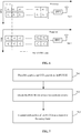
- step 702 the PUCCH is divided into at least two portions in time.
- step 703 the PUCCH is transmitted in such a way that each portion is transmitted in a respective frequency band.
- step 701 the specific placement of RS symbols and UCI symbols may refer to the embodiments described in connection with FIG. 3 and the examples described in connection with FIG. 4A and FIG. 4B , and thus will be not elaborated here.
- step 502 may be executed before step 702.
- step 502 may be executed before step 702.
- FIG.8A and FIG. 8B illustrate two examples of intra-slot hopping for PUCCH with long duration in an uplink-only slot according to the disclosure, which use the same RS designs as shown in FIG. 4A and FIG. 4B in the above. In general, it would be good to consider such operations when designing DMRS symbols and avoid to have two sets of DMRS design, one for non-hopping and one for hopping.
- FIG. 8A and FIG. 8B illustrate two examples of intra-slot hopping for PUCCH with long duration in an uplink-only slot according to the disclosure, which use the same RS designs as shown in FIG. 4A and FIG. 4B in the above. In general, it would be good to consider such operations when designing DMRS symbols and avoid to have two sets of DMRS design, one for non-hopping and one for hopping.
- FIG. 8A and FIG. 8B illustrate two examples of intra-slot hopping for PUCCH with long duration in an uplink-only slot according to the disclosure, which use the same RS designs as shown in
- 8C illustrates an intra-slot hopping for PUCCH with long duration in an uplink-centric slot according to the disclosure. Since the uplink-centric slot have more uplink symbols available for PUCCH relative to the uplink-centric slots, it may be more worth applying intra-slot frequency hopping for the uplink-centric slot.
- frequency hopping particularly the intra-slot hopping
- the UCI in the PUCCH could be transmitted in different frequency bands, and thus the frequency diversity gain is improved.
- an information transmission apparatus is provided according to some embodiments of the disclosure.
- the information transmission apparatus 900 includes a placement module 901, and a transmission module 902.
- the placement module 901 may be realized by a software module stored in a memory and executable by a processor, or may be hardware circuits, or may be a combination thereof. Therefore, the placement module 901 may be referred to as a placement circuit in some cases.
- the transmission module 902 may be realized by a transmitter circuit including multiple antennas.
- the placement module 901 may be configured to place a first RS symbol at beginning of a PUCCH, and place UCI symbols after the first RS symbol in the PUCCH.
- the transmission module 902 may be configured to transmit the PUCCH.
- the transmitter may be configured to perform one of the following: transmit the PUCCH in one or more slots of a first type, wherein all symbols in each of the slots of the first type are uplink, which are dedicated for transmitting the PUCCH; transmit the PUCCH in one or more slots of a second type, wherein more than one half of symbols in each of the slots of the second type are uplink, which are dedicated for transmitting the PUCCH; and transmit the PUCCH in multiple slots comprising one or more slots of the first type and one or more slots of the second type, and the placement module may be configured to place the first RS symbol at the beginning of the PUCCH, in each of the slots of the first or second type.
- the placement module 901 may further be configured to perform at least one of the following: place a second RS symbol at end of the PUCCH, in each of the slots of the first or second type; and place one or more third RS symbols evenly in between the UCI symbols, in the PUCCH in each of the slots of the first or second type.
- the placement module 901 may further be configured to place one or two RS symbols immediately after every n contiguous UCI symbols, in each of the slots of the first or second type, until a last symbol in the slot is filled by an RS or UCI symbol, where n is an integer greater than or equal to 1.
- the apparatus 900 may further include a transmit diversity module 903, configured to perform Space-Time Block Coding (STBC) on at least a portion of the UCI symbols in the PUCCH to build STBC codes.
- STBC Space-Time Block Coding
- transmit diversity module 903 may be realized by a software module stored in a memory and executable by a processor, or may be hardware circuits, or may be a combination thereof. Therefore, the transmit diversity module 903 may be referred to as a transmit diversity circuit or a transmit diversity coder in some cases.
- the apparatus 900 may further include a sequence generation module 905.
- the sequence generation module 905 may be realized by a software module stored in a memory and executable by a processor, or may be hardware circuits, or may be a combination thereof. Therefore, the sequence generation module 905 may be referred to as a sequence generation circuit or a sequence generator in some cases.
- the sequence generation module 905 may be configured to for each of modulated symbols carrying UCI in the PUCCH, where the UCI symbols comprise m UCI symbols in time, where m is an integer, and greater than or equal to 2.
- the transmit diversity module 904 is configured to: for (2 k -1) th and (2 k ) th UCI symbols in time, where k is a positive integer and smaller than or equal to m/2, directly use elements of the orthogonal sequences corresponding to the (2 k -1) th and (2 k ) th UCI symbols to build a first set of pairs of STBC codes, and perform conjugation transformation on the elements of the generated orthogonal sequences corresponding to the (2 k -1) th and (2 k ) th UCI symbols to build a second set of pairs of STBC codes.
- in the transmission module 903 may be configured to: transmit the PUCCH with the first set of pairs of STBC codes via a first antenna; and transmit the PUCCH with the second set of pairs of STBC codes via a second antenna.
- the transmit diversity module 904 may further configured to perform Cyclic Delay Diversity (CDD) or Space Orthogonal-Resource Transmit Diversity (SORTD) on a last DCI symbol in time among the m DCI symbols to build CDD or SORTD codes for the last DCI symbol.
- CDD Cyclic Delay Diversity
- SORTD Space Orthogonal-Resource Transmit Diversity
- the transmission module 903 may further be configured to divide the PUCCH transmitted in a single one of the first or second slots into a first portion and a second portion; transmit the first portion of the PUCCH in a first frequency band; and transmit the second portion of the PUCCH in a second frequency band.
- the PUCCH may be divided such that the second portion of the PUCCH begins with an RS symbol.
- FIG. 10 is a simplified structural diagram of a UE according to an embodiment of the disclosure.
- the UE 1000 may include a processor 1001, a memory 1002, a transmitter 1003 having multiple antennas and other parts (e.g., a touch screen, not shown).
- the memory 1002 stores program instructions, which when executed by the processor 1001, cause the processor 1001 to perform at least one of the method described in connection with FIGs. 1 , 5 and 7 .
- the apparatus as shown in Fig. 9 may be implemented in the UE 1000.
- the computer programs can be stored in a computer readable storage medium and executed on a corresponding hardware platform (e.g., system, equipment, apparatus, device and the like) to perform one or a combination of the steps in the method embodiments.
- a hardware platform e.g., system, equipment, apparatus, device and the like
- ICs Integrated Circuits
- Respective devices or functional modules or functional units in the above embodiments can be implemented using general computing devices, which can be located in a single computing apparatus or distributed on a network including multiple computing devices.
- a computer readable storage medium can be magnetic disks and / or optical disks, such as Read Only Memories (ROMs), and the like.
- front-loaded RS is used in RS design for PUCCH with long duration, which achieves low latency of services in the 5G TR system.
- STBC When STBC is used as transmit diversity of PUCCH with long duration, it would bring superior transmit diversity gain, does not require additional sequence resources, and improve coverage and robustness performances.
- Rest RS symbols may be placed with one DMRS symbol for every n UCI symbols.
- Frequency hopping may also be used for PUCCH with long duration, thus obtaining more frequency diversity gain.
Description
- The present disclosure relates to the technical field of communications, and particularly an information transmission method and apparatus and storage medium.
- In a Fourth-Generation (4G) Long Term Evolution (LTE) communication system, as shown in
FIG.1 , Physical Uplink Control Channel (PUCCH) is transmitted in a full uplink subframe with fixed number of symbols (e.g., 14 symbols) at the edges of system bandwidth, and is used to carry uplink control information (UCI) such as Ack/NACK for downlink Physical Downlink Shared Channel (PDSCH) transmission and channel state information (CSI) feedback from the User Equipment (UE). - When it comes to a Fifth-Generation (5G) New Radio (NR) communication system, due to the introduction of higher frequency, the larger path loss could deteriorate the cell coverage. In order to transmit uplink control information (UCI) for the cell edge UE or wherever UE has a coverage issue, a concept of PUCCH with long duration (also referred to as PUCCH with long format) is proposed. Here, the term "long duration" generally means that at least 4 symbols can be transmitted in the PUCCH. Accordingly, design of the PUCCH with long duration to achieve desired performances becomes an issue to be solved.
- A method and apparatus according to the preamble of the independent claims can be found in NTT DOCOMO ET AL: "Summary of [87-36]: Mini-slot designs for NR", 3GPP DRAFT; R1-1700617, 3RD GENERATION PARTNERSHIP PROJECT (3GPP), MOBILE COMPETENCE CENTRE; 650, ROUTE DES LUCIOLES; F-06921 SOPHIA-ANTIPOLIS CEDEX; FRANCE, vol. RAN WG1, no. Spokane, USA; 20170116 - 20170120, 17 January 2017, INTEL CORPORATION: "Aspects of reference signal design for URLLC services", 3GPP DRAFT; R1-1612581 INTEL - URLLC REFSIG, 3RD GENERATION PARTNERSHIP PROJECT (3GPP), MOBILE COMPETENCE CENTRE; 650, ROUTE DES LUCIOLES; F-06921 SOPHIA-ANTIPOLIS CEDEX; FRANCE, vol. RAN WG1, no. Reno, USA; 20161114 - 20161118, 13 November 2016, and NTT DOCOMO ET AL: "UL control channel structure in long duration", 3GPP DRAFT; R1-1700623, 3RD GENERATION PARTNERSHIP PROJECT (3GPP), MOBILE COMPETENCE CENTRE; 650, ROUTE DES LUCIOLES; F-06921 SOPHIA-ANTIPOLIS CEDEX; FRANCE, vol. RAN WG1, no. Spokane, USA; 20170116 - 20170120, January 16, 2017.
- An objective of this disclosure is to provide an information transmission method, which is capable of achieving low latency of services. The invention is defined by the independent claims. The method includes that an RS symbol is placed at beginning of a PUCCH, UCI symbols are placed after the RS symbol in the PUCCH, and the PUCCH is transmitted.
- In some embodiments, the PUCCH may be transmitted in one or more slots of a first type, wherein all symbols in each of the slots of the first type are uplink, which are dedicated for transmitting the PUCCH; or the PUCCH may be transmitted in one or more slots of a second type, wherein more than one half of symbols in each of the slots of the second type are uplink, which are dedicated for transmitting the PUCCH; or the PUCCH may be transmitted in multiple slots comprising one or more slots of the first type and one or more slots of the second type. The first RS symbol may be transmitted at the beginning of the PUCCH, in each of the slots of the first or second type.
- In some embodiments, a second RS symbol may further be placed at end of the PUCCH, in each of the slots of the first or second type; and/or one or more third RS symbols are placed evenly in between the UCI symbols, in the PUCCH in each of the slots of the first or second type.
- In some embodiments, one or two RS symbols may be placed immediately after every n contiguous UCI symbols, in each of the slots of the first or second type, until a last symbol in the slot is filled by an RS or UCI symbol, where n is an integer greater than or equal to 1.
- In some embodiments, before transmitting the PUCCH, Space-Time Block Coding (STBC) may be performed on at least a portion of the UCI symbols in the PUCCH to build STBC codes.
- In some embodiments, an orthogonal sequence may be generated for each of modulated symbols carrying UCI in the PUCCH, wherein the UCI symbols comprise m UCI symbols in time, where m is an integer, and greater than or equal to 2; the performing STBC on at least a portion of UCI symbols may include: for (2k-1) th and (2k) th UCI symbols in time, the elements of the orthogonal sequences corresponding to the (2k-1) th and (2k) th UCI symbols are directly used to build a first set of pairs of STBC codes, and conjugation transformation on the elements of the generated orthogonal sequences corresponding to the (2k-1) th and (2k) th UCI symbols is performed to build a second set of pairs of STBC codes; the PUCCH with the first set of pairs of STBC codes may be transmitted via a first antenna, and the PUCCH with the second set of pairs of STBC codes may be transmitted via a second antenna, where k is a positive integer and smaller than or equal to m/2.
- In some embodiments, when m is an odd number, before transmitting the PUCCH, Cyclic Delay Diversity (CDD) or Space Orthogonal-Resource Transmit Diversity (SORTD) may be performed on a last DCI symbol in time among the m DCI symbols to build CDD or SORTD codes for the last DCI symbol.
- In some embodiments, before the transmitting the PUCCH, the PUCCH transmitted in a single one of the first or second slots may be divided into a first portion and a second portion; the first portion of the PUCCH may be transmitted in a first frequency band; and the second portion of the PUCCH may be transmitted in a second frequency band.
- In some embodiments, the PUCCH may be divided such that the second portion of the PUCCH begins with an RS symbol.
- Another objective of this disclosure is to provide an information transmission apparatus, which is capable of achieving low latency of services. The apparatus includes a processor; and one or more modules stored on a memory and executable by the processor, the one or more modules include: a placement module, configured to place a first RS symbol at beginning of a Physical Uplink Control Channel (PUCCH), and place UCI symbols after the first RS symbol in the PUCCH; and a transmitter, configured to transmit the PUCCH.
- In some embodiments, the transmitter may be configured to perform one of the following: transmit the PUCCH in one or more slots of a first type, wherein all symbols in each of the slots of the first type are uplink, which are dedicated for transmitting the PUCCH; transmit the PUCCH in one or more slots of a second type, wherein more than one half of symbols in each of the slots of the second type are uplink, which are dedicated for transmitting the PUCCH; and transmit the PUCCH in multiple slots comprising one or more slots of the first type and one or more slots of the second type; and the RS placement module may be configured to place the first RS symbol at the beginning of the PUCCH, in each of the slots of the first or second type.
- In some embodiments, the placement module may further be configured to perform at least one of the following: place a second RS symbol at end of the PUCCH, in each of the slots of the first or second type; and place one or more third RS symbols evenly in between the UCI symbols, in the PUCCH in each of the slots of the first or second type.
- In some embodiments, the placement module may further be configured to place one or two RS symbols immediately after every n contiguous UCI symbols, in each of the slots of the first or second type, until a last symbol in the slot is filled by an RS or UCI symbol, where n is an integer greater than or equal to 1.
- In some embodiments, the one or more modules may further include a transmit diversity module, configured to perform Space-Time Block Coding (STBC) on at least a portion of the UCI symbols in the PUCCH to build STBC codes.
- In some embodiments, the one or more modules may further include a sequence generation module configured to generate an orthogonal sequence for each of modulated symbols carrying UCI in the PUCCH, where the UCI symbols comprise m UCI symbols in time, where m is an integer, and greater than or equal to 2; the transmit diversity module may be configured to: for (2k-1) th and (2k) th UCI symbols in time, directly use elements of the orthogonal sequences corresponding to the (2k-1) th and (2k) th UCI symbols to build a first set of pairs of STBC codes, and perform conjugation transformation on the elements of the generated orthogonal sequences corresponding to the (2k-1) th and (2k) th UCI symbols to build a second set of pairs of STBC codes; the transmitter may be configured to: transmit the PUCCH with the first set of pairs of STBC codes via a first antenna; and transmit the PUCCH with the second set of pairs of STBC codes via a second antenna, where k is a positive integer and smaller than or equal to m/2.
- In some embodiments, when m is an odd number, before the PUCCH is transmitted, the transmit diversity module may further be configured to perform Cyclic Delay Diversity (CDD) or Space Orthogonal-Resource Transmit Diversity (SORTD) on a last DCI symbol in time among the m DCI symbols to build CDD or SORTD codes for the last DCI symbol.
- In some embodiments, the transmitter may further be configured to: divide the PUCCH transmitted in a single one of the first or second slots into a first portion and a second portion; transmit the first portion of the PUCCH in a first frequency band; and transmit the second portion of the PUCCH in a second frequency band.
- In some embodiments, the PUCCH may be divided such that the second portion of the PUCCH begins with an RS symbol.
- The disclosure also provides a non-transitory computer readable storage radium, having instructions stored therein, which when executed by a processor, causes the processor to execute the method as described above.
- According to the disclosure, front-loaded RS is used in RS design for PUCCH with long duration, which achieves low latency of services in the 5G TR system. Rest RS symbols may be placed with one DMRS symbol for every n UCI symbols, where n is an integer greater than or equal to 1. Frequency hopping may also be used for PUCCH with long duration, thus obtaining more frequency diversity gain. When STBC is used as transmit diversity of PUCCH with long duration, it would bring superior transmit diversity gain, does not require additional sequence resources, and improve coverage and robustness performances.
-
-
FIG. 1 illustrates a typical PUCCH transmission scheme in the 4G LTE system; -
FIG. 2 illustrates several slot structure examples in the 5G NR system; -
FIG. 3 illustrates a flowchart of an information transmission method according to an embodiment of the disclosure; -
FIG. 4A illustrates some examples of RS locations for PUCCH with long duration in one slot according to the disclosure; -
FIG. 4B illustrates an example of RS locations for PUCCH with long duration in multiple uplink only slots according to the disclosure; -
FIG. 5 illustrates a flowchart of an information transmission method according to an embodiment of the disclosure; -
FIG. 6 illustrates a schematic view of building STBC codes as transmit diversity for PUCCH with long duration according to the disclosure; -
FIG. 7 illustrates a flowchart of an information transmission method according to an embodiment of the disclosure; and -
FIG. 8A illustrates an example of intra-slot hopping for PUCCH with long duration in an uplink-only slot according to the disclosure; -
FIG. 8B illustrates another example of intra-slot hopping for PUCCH with long duration in an uplink-only slot according to the disclosure; -
FIG. 8C illustrates an example of intra-slot hopping for PUCCH with long duration in an uplink-centric slot according to the disclosure; -
FIG. 9 illustrates a block diagram of an information transmission apparatus according to an embodiment of the disclosure; -
FIG. 10 illustrates a simplified structure diagram of a UE according to an embodiment of the disclosure. - Various aspects are now described with reference to the drawings. In the following description, for purposes of explanation, numerous specific details are set forth in order to provide a thorough understanding of one or more aspects. It may be evident, however, that such aspects may be practiced without these specific details.
- Various aspects are described herein in connection with a user equipment (UE), which can be a wireless terminal. The UE can also be called a system, device, subscriber unit, subscriber station, mobile station, mobile, mobile device, remote station, remote terminal, access terminal, user terminal, terminal, communication device, user agent, or user device. The UE may be a cellular telephone, a satellite phone, a cordless telephone, a Session Initiation Protocol (SIP) phone, a wireless local loop (WLL) station, a personal digital assistant (PDA), a handheld device having wireless connection capability, a computing device, or other processing devices connected to a wireless modem. Moreover, various aspects are described herein in connection with a base station. A base station may be utilized for communicating with wireless terminal(s) and may also be referred to as an access point, a Node B, evolved Node B (eNB), H(e)NB, or some other terminology.
- In order to provide a thorough understanding of the information transmission method and apparatus according to the embodiments of the disclosure, first of all, the slot structures used in the 5G NR system will be introduced hereinafter.
FIG. 2 illustrates several slot structure examples in the 5G NR system. As an example, the slot may be classified into uplink only slot, uplink-centric slot and downlink-centric slot. - For an uplink only slot, all of the symbols in the uplink only slot are used for uplink (UL) transmission, and the PUCCH with long duration may be transmitted in the middle part of the system bandwidth (shown in
FIG. 2 ) or the edges of the system bandwidth (not shown), or the like. - For an uplink-centric slot, symbols for both UL transmission and downlink (DL) transmission are included in the uplink centric slot, where there are more uplink symbols, there is a guard period (GP) between DL/UL transmission to allow UE to switch from DL reception to UL transmission, and the PUCCH with long duration may be transmitted the middle part of the system bandwidth (shown in
FIG. 2 ) or the edges of the system bandwidth (not shown), or the like. - For a downlink-centric slot, symbols for both UL transmission and downlink (DL) transmission are included in the downlink-centric slot, where there are more downlink symbols, there is a guard period (GP) between DL/UL transmission to allow UE to switch from DL reception to UL transmission. As the number of uplink symbols in the downlink-centric slot relatively small, the downlink-centric slot may not be suitable for transmitting the PUCCH with long duration.
- As DFT-S-OFDM will be used for PUCCH with long duration, and reference signal (RS) and uplink control information (UCI) would be multiplexed in the time division multiplex (TDM) manner, the demodulation reference signal (DMRS, the same meaning as RS here, and may also be referred to as pilot signal) for PUCCH could occupy their own symbols. In order to achieve low latency, which is a key requirement for some services in the 5G TR system, the inventor has found that RS design is an important design aspect for PUCCH with long duration. In other words, locations of DMRS needs to be re-designed from that in the LTE system.
- To cope with this, the front-loaded DMRS principle is used for PUCCH with long duration in the present invention.
- According to some embodiments of the disclosure, an information transmission method is provided. The method may be applied in a UE. As shown in
FIG. 3 , the method may include the following steps. - In
step 301, an RS symbol is placed at beginning of a PUCCH, UCI symbols are placed after the RS symbol in the PUCCH. - In
step 302, the PUCCH is transmitted. Specifically, the PUCCH is transmitted to a base station which in communication with the UE. - In one or more embodiments,
step 301 may further include placement/locations of the rest RS symbols. In an embodiment, an RS symbol is placed at the end of the PUCCH, which improves the accuracy of demodulation of the UCI at the network side. In an embodiment, one or more RS symbols may be placed evenly in between the UCI symbols. Specifically, rest DMRS symbols are placed with one DMRS symbol for every n UCI symbols (where n is an integer greater than or equal to 1), which will be later described in detail. - In practice, the locations for the RS symbols and for the DCI symbols in the PUCCH may be pre-determined. That is, the actions for placement of RS symbols and DCI symbols in
step 301 described above in the various embodiments may be combined as desired, and executed in any order or concurrently. -
FIG. 4A illustrates some examples of RS locations for PUCCH with long duration in one slot according to the disclosure. A couple of slot structures are shown in the figure, which ranges from uplink-only slot to two uplink-centric slots with both DL/UL transmissions. The principles of RS placement used in these examples include: 1) front loaded DMRS at the beginning of the PUCCH; and 2) the rest DMRS symbols are placed with one DMRS symbol for every n UCI symbols, where n is an integer greater than or equal to 1. - Specifically, as shown in FIF. 4A, uplink only slots and uplink-centric slots are used for transmitting PUCCH with long duration. Here, each of the slots includes, seven symbols. However, it is to be noted that this is just an example, and a slot may, of course, includes more or less than seven symbols.
- For the uplink only slot shown in the top of
FIG. 4 , all the symbols in the uplink only slot are uplink symbols and are dedicated for transmitting the PUCCH; the RS symbols are placed in the first symbol, the fourth symbol (which is in the middle of the slot) and the last symbol of the slot. It can be noticed that such a RS placement allow two contiguous UCI symbols in between two RS symbols, which facilitates the implementation of STBC transmit diversity scheme which will be later described in detail. - Of course, when another diversity scheme different from the STBC is employed, there is no need to keep two contiguous UCI symbols in between two RS symbols. For example, there may be just one UCI symbol in between two RS symbols.
- For the uplink-centric slot shown in the middle of
FIG. 4 , there is one symbol (the first symbol) for DL transmission, five symbols for UL transmission, a guard period for switching from the DL transmission to UL transmission. The five symbols are dedicated for transmitting the PUCCH, where RS symbols are placed in the first and fourth symbols. It can be noticed that such a RS placement also allow two contiguous UCI symbols in between two RS symbols; and meanwhile, there is an orphan DCI symbol left (i.e., the last DCI symbol) in the PUCCH. - For the uplink-centric slot shown in the bottom of
FIG. 4 , there are two symbols (the first and second symbols) for DL transmission, four symbols for UL transmission, a guard period for switching from the DL transmission to UL transmission. The four symbols are dedicated for transmitting the PUCCH, where RS symbols are placed in the first and fourth symbols, i.e., at the beginning and end of the PUCCH respectively. It can be noticed that such a RS placement also allows two contiguous UCI symbols in between two RS symbols. -
FIG. 4B illustrates an example of RS locations for PUCCH with long duration in multiple uplink only slots according to the disclosure. In this example, uplink-only slots are aggregated and assigned for PUCCH. It can be noticed that placement of DMRS provides quite even distribution of RS within the aggregated slots for PUCCH and allow two contiguous UCI symbols in between two DMRS symbols to facilitate the implementation of STBC transmit diversity scheme. Another difference from the examples inFIG. 4A lies in that, two contiguous RS symbols (located in the fourth and fifth symbols) are placed immediately after every two contiguous UCI symbols, in each of the slots of the first or second type, until a last symbol in the slot is filled by an RS or UCI symbol. - It is to noted that the placement of two contiguous RS symbols as shown in
FIG. 4B can be applied in the scenario ofFIG. 4A , in which no slot aggregation is used. - Another design aspect for the PUCCH with long duration accounts for improved coverage and robustness performance for the PUCCH. Unlike data channel, control channel does not have re-transmission mechanism to correct/improve its first transmission. For the 5G NR system, due to the introduction of higher frequency, the larger path loss could deteriorate the cell coverage. For downlink, the use of beamforming (BF) could compensate some of such path losses and improve the cell coverage. However, BF in uplink may not be as effective as in downlink, therefore, cell coverage could be an issue. To solve this, Discrete Fourier Transform-Spread OFDM (DFT-S-OFDM) waveform is adopted in uplink for PUCCH with long duration which leads to lower PAPR and thus smaller power back-off and larger coverage. To further improve that, transmit diversity is considered in the present invention.
- For transmit diversity, a couple of schemes could be considered, which include Alamouti based transmit diversity, cyclic delay diversity (CDD), Space orthogonal-resource transmit diversity (SORTD). There are pros and cons for each of the schemes, as shown in Table 1.
Table 1 Comparing among different transmit diversity schemes for PUCCH Transmit diversity schemes Pros Cons STBC Good diversity performance as the STBC code is orthogonal, does not need more sequence resource Need pair of symbols in time CDD easy to implement, no requirement on pair of symbols Relative weaker diversity as compared with other schemes SORTD Good diversity performance as orthogonal sequences are used. No requirement on pair of symbols Double the sequence resources. - As DFT-S-OFDM is adopted as PUCCH with long duration, orthogonal sequences like Zadoff-Chu set of sequences could be used as the modulation sequences for UCI and RS. Such sequences are mapped along frequency and multiple sequences could be used to modulated UCIs from the same/different UEs before being multiplexed on the same symbol. As each sequence is formed by a set of complex values which cannot be re-arranged, SFBC could not be used as the transmit diversity here.
- In view of this, STBC is proposed in the present invention to be used as transmit diversity for PUCCH with long duration.
- According to some embodiments of the disclosure, an information transmission method is provided. The method may be applied in a UE. As shown in
FIG. 5 , the method may include the following steps. - In
step 501, RS symbols and UCI symbols are placed in the PUCCH. - In
step 502, Space-Time Block Coding (STBC) is performed on at least a portion of the UCI symbols in the PUCCH to build STBC codes. - In
step 503, the PUCCH is transmitted. Specifically, the PUCCH is transmitted to a base station which in communication with the UE. - For
step 501, the specific placement of RS symbols and UCI symbols may refer to the embodiments described in connection withFIG. 3 and the examples described in connection withFIGs. 4A and4B , and thus will be not elaborated here. - Regarding the STBC, specifically, in an example, the UCI may be modulated using a modulation scheme such as Binary Phase Shift Keying(BPSK) or Quadrature Phase Shift Keying (QPSK), and then an orthogonal sequence is generated for each of modulated symbols carrying UCI in the PUCCH, where the UCI symbols comprise m UCI symbols in time, where m is an integer, and greater than or equal to 2. After the orthogonal sequences are generated, STBC is performed, as described in the following.
-
FIG. 6 illustrates a schematic view of building STBC codes as transmit diversity for PUCCH with long duration according to the disclosure. Taking the (2k-1) th and (2k) th UCI symbols a and b for example, where k is a positive integer and smaller than or equal to m/2, the generated orthogonal sequences are ai and bi respectively, where i = 0,1, ..., n, the elements of the orthogonal sequences ai and bi are directly used to build a first set of pairs of STBC codes, for example, the first pair is (a 0 ,b 0), the second pair is (a 1,b 1),... and the nth pair is (an ,bn ). Additionally, conjugation transformation is performed on the elements of the generated orthogonal sequences ai and bi to build a second set of pairs of STBC codes, for example, the first pair is


- As shown in
FIG. 6 , before transmitting the PUCCH, inverse Fast Fourier Transform (IFFT) is performed on the first and second set of pairs of STBC codes, together with the orthogonal sequences corresponding to the RS symbols, to transform them into the time domain. The IFFT is known to one of ordinary skill in the art, and will not be elaborated here. Then, the PUCCH with the first set of pairs of STBC codes is transmitted via afirst antenna Ant 1 and the PUCCH with the second set of pairs of STBC codes is transmitted via asecond antenna Ant 2. - In the case that STBC is used as transmit diversity for PUCCH with long duration, the UCI transmitted on PUCCH could be spread/repeated and transmitted on same/different symbols within the time-frequency resources assigned for PUCCH. a As the STBC codes areorthogonal, good diversity performance can be implemented and thus the coverage and robustness performance of PUCCH with long duration is improved; and additionally, no more sequence resources are need.
- As pair of symbols in time are needed to build STBC codes, in some embodiments, orphan symbol (for example, when m is an odd number) may be left in the time domain. In this case, other transmit diversity schemes such as CDD or SORTD could be used for the orphan symbol.
- In order to increase frequency diversity gain, the present invention further proposes frequency hopping as a yet another design aspect of PUCCH with long duration.
- According to some embodiments of the disclosure, an information transmission method is provided. The method may be applied in a UE. As shown in
FIG.7 , the method may include the following steps. - In
step 701, RS symbols and UCI symbols are placed in the PUCCH. - In
step 702, the PUCCH is divided into at least two portions in time. - In
step 703, the PUCCH is transmitted in such a way that each portion is transmitted in a respective frequency band. - In an embodiment, for
step 701, the specific placement of RS symbols and UCI symbols may refer to the embodiments described in connection withFIG. 3 and the examples described in connection withFIG. 4A andFIG. 4B , and thus will be not elaborated here. - Of course, transmit diversity may be combined with frequency hopping to achieve optimum performance. For example, step 502 may be executed before
step 702. Such a combination can be understood by one of ordinary skill in the art, and will not be elaborated here. - For frequency hopping, intra-slot and inter-slot hopping of PUCCH with long duration could be used. In terms of intra-slot hopping, the portion (symbols) that hops to another part of frequency may need to have RS symbol to start with.
FIG.8A and FIG. 8B illustrate two examples of intra-slot hopping for PUCCH with long duration in an uplink-only slot according to the disclosure, which use the same RS designs as shown inFIG. 4A andFIG. 4B in the above. In general, it would be good to consider such operations when designing DMRS symbols and avoid to have two sets of DMRS design, one for non-hopping and one for hopping.FIG. 8C illustrates an intra-slot hopping for PUCCH with long duration in an uplink-centric slot according to the disclosure. Since the uplink-centric slot have more uplink symbols available for PUCCH relative to the uplink-centric slots, it may be more worth applying intra-slot frequency hopping for the uplink-centric slot. - In this embodiment, frequency hopping, particularly the intra-slot hopping, is used for PUCCH with long duration, the UCI in the PUCCH could be transmitted in different frequency bands, and thus the frequency diversity gain is improved.
- Based on the several information transmission method embodiments described above, an information transmission apparatus is provided according to some embodiments of the disclosure.
- As shown in
FIG. 9 , theinformation transmission apparatus 900 includes aplacement module 901, and atransmission module 902. In practice, theplacement module 901 may be realized by a software module stored in a memory and executable by a processor, or may be hardware circuits, or may be a combination thereof. Therefore, theplacement module 901 may be referred to as a placement circuit in some cases. Thetransmission module 902 may be realized by a transmitter circuit including multiple antennas. - The
placement module 901 may be configured to place a first RS symbol at beginning of a PUCCH, and place UCI symbols after the first RS symbol in the PUCCH. - The
transmission module 902 may be configured to transmit the PUCCH. - In an embodiment, the transmitter may be configured to perform one of the following: transmit the PUCCH in one or more slots of a first type, wherein all symbols in each of the slots of the first type are uplink, which are dedicated for transmitting the PUCCH; transmit the PUCCH in one or more slots of a second type, wherein more than one half of symbols in each of the slots of the second type are uplink, which are dedicated for transmitting the PUCCH; and transmit the PUCCH in multiple slots comprising one or more slots of the first type and one or more slots of the second type, and the placement module may be configured to place the first RS symbol at the beginning of the PUCCH, in each of the slots of the first or second type.
- In an embodiment, the
placement module 901 may further be configured to perform at least one of the following: place a second RS symbol at end of the PUCCH, in each of the slots of the first or second type; and place one or more third RS symbols evenly in between the UCI symbols, in the PUCCH in each of the slots of the first or second type. - In an embodiment, the
placement module 901 may further be configured to place one or two RS symbols immediately after every n contiguous UCI symbols, in each of the slots of the first or second type, until a last symbol in the slot is filled by an RS or UCI symbol, where n is an integer greater than or equal to 1. - In an embodiment, the
apparatus 900 may further include a transmitdiversity module 903, configured to perform Space-Time Block Coding (STBC) on at least a portion of the UCI symbols in the PUCCH to build STBC codes. In practice, transmitdiversity module 903 may be realized by a software module stored in a memory and executable by a processor, or may be hardware circuits, or may be a combination thereof. Therefore, the transmitdiversity module 903 may be referred to as a transmit diversity circuit or a transmit diversity coder in some cases. - In an embodiment, the
apparatus 900 may further include a sequence generation module 905. In practice, the sequence generation module 905 may be realized by a software module stored in a memory and executable by a processor, or may be hardware circuits, or may be a combination thereof. Therefore, the sequence generation module 905 may be referred to as a sequence generation circuit or a sequence generator in some cases. The sequence generation module 905 may be configured to for each of modulated symbols carrying UCI in the PUCCH, where the UCI symbols comprise m UCI symbols in time, where m is an integer, and greater than or equal to 2. In this embodiment, the transmitdiversity module 904 is configured to: for (2k-1) th and (2k) th UCI symbols in time, where k is a positive integer and smaller than or equal to m/2, directly use elements of the orthogonal sequences corresponding to the (2k-1) th and (2k) th UCI symbols to build a first set of pairs of STBC codes, and perform conjugation transformation on the elements of the generated orthogonal sequences corresponding to the (2k-1) th and (2k) th UCI symbols to build a second set of pairs of STBC codes. in thetransmission module 903 may be configured to: transmit the PUCCH with the first set of pairs of STBC codes via a first antenna; and transmit the PUCCH with the second set of pairs of STBC codes via a second antenna. - In an embodiment, when m is an odd number, before the PUCCH is transmitted, the transmit
diversity module 904 may further configured to perform Cyclic Delay Diversity (CDD) or Space Orthogonal-Resource Transmit Diversity (SORTD) on a last DCI symbol in time among the m DCI symbols to build CDD or SORTD codes for the last DCI symbol. - In an embodiment, the
transmission module 903 may further be configured to divide the PUCCH transmitted in a single one of the first or second slots into a first portion and a second portion; transmit the first portion of the PUCCH in a first frequency band; and transmit the second portion of the PUCCH in a second frequency band. The PUCCH may be divided such that the second portion of the PUCCH begins with an RS symbol. -
FIG. 10 is a simplified structural diagram of a UE according to an embodiment of the disclosure. TheUE 1000 may include aprocessor 1001, amemory 1002, a transmitter 1003 having multiple antennas and other parts (e.g., a touch screen, not shown). Thememory 1002 stores program instructions, which when executed by theprocessor 1001, cause theprocessor 1001 to perform at least one of the method described in connection withFIGs. 1 ,5 and7 . The apparatus as shown inFig. 9 may be implemented in theUE 1000. - The benefits of the apparatus described here correspond to those described for the information transmission methods, and thus are omitted here.
- Those skilled in the art will appreciate that all or a part of the steps in the above embodiments can be implemented by computer programs. The computer programs can be stored in a computer readable storage medium and executed on a corresponding hardware platform (e.g., system, equipment, apparatus, device and the like) to perform one or a combination of the steps in the method embodiments.
- Optionally, all or a part of the steps in the above embodiments can be implemented using Integrated Circuits (ICs). These steps can be implemented by one or more IC modules. As such, the present invention is not limited to any specific combination of hardware circuitry and software.
- Respective devices or functional modules or functional units in the above embodiments can be implemented using general computing devices, which can be located in a single computing apparatus or distributed on a network including multiple computing devices.
- When respective devices or functional modules or functional units in the above embodiments are implemented in the form of software functional modules and then sold or used as an independent product, they can be stored in a computer readable storage medium. The aforementioned computer readable storage medium can be magnetic disks and / or optical disks, such as Read Only Memories (ROMs), and the like.
- According to the disclosure, front-loaded RS is used in RS design for PUCCH with long duration, which achieves low latency of services in the 5G TR system. When STBC is used as transmit diversity of PUCCH with long duration, it would bring superior transmit diversity gain, does not require additional sequence resources, and improve coverage and robustness performances. Rest RS symbols may be placed with one DMRS symbol for every n UCI symbols. Frequency hopping may also be used for PUCCH with long duration, thus obtaining more frequency diversity gain.
Claims (10)
- An information transmission method, comprising:generating an orthogonal sequence for each of modulated symbols carrying Uplink Control Information UCI in a Physical Uplink Control Channel PUCCH, wherein a first Reference Signal RS symbol is placed at beginning of the PUCCH, UCI symbols are placed after the first RS symbol, and the UCI symbols comprise m UCI symbols in time, where m is an integer, and greater than or equal to 2,for k= 1 up to or equal to m/2, wherein k is a positive integer; and m is an even integer, greater or equal to 2, for (2k-1) th and (2k) th UCI symbols in time, directly using elements of the generated orthogonal sequences corresponding to the (2k-1) th and (2k) th UCI symbols to build a first set of pairs of Space-Time Block Coding STBC codes, andperforming conjugation transformation on the elements of the generated orthogonal sequences corresponding to the (2k-1) th and (2k) th UCI symbols to build a second set of pairs of STBC codes;transmitting the PUCCH with the first set of pairs of STBC codes via a first antenna; andtransmitting the PUCCH with the second set of pairs of STBC codes via a second antenna.
- The method according to claim 1, wherein the transmitting the PUCCH with the first set of pairs of STBC codes via the first antenna; and transmitting the PUCCH with the second set of pairs of STBC codes via the second antenna comprises one of the following:transmitting the PUCCH with the first set of pairs of STBC codes via the first antenna; and transmitting the PUCCH with the second set of pairs of STBC codes via the second antenna in one or more slots of a first type, wherein all symbols in each of the slots of the first type are uplink, which are dedicated for transmitting the PUCCH;transmitting the PUCCH with the first set of pairs of STBC codes via the first antenna; and transmitting the PUCCH with the second set of pairs of STBC codes via the second antenna in one or more slots of a second type, wherein more than one half of symbols in each of the slots of the second type are uplink, which are dedicated for transmitting the PUCCH; andtransmitting the PUCCH with the first set of pairs of STBC codes via the first antenna; and transmitting the PUCCH with the second set of pairs of STBC codes via the second antenna in multiple slots comprising one or more slots of the first type and one or more slots of the second type, andwherein the placing the first RS symbol at beginning of the PUCCH comprises:
placing the first RS symbol at the beginning of the PUCCH, in each of the slots of the first or second type. - The method according to claim 2, further comprising:
placing one or two RS symbols immediately after every n contiguous UCI symbols, in each of the slots of the first or second type, until a last symbol in the slot is filled by an RS or UCI symbol, wherein n is an integer greater than or equal to 1. - The method according to any of claims 1 to 3, wherein transmitting the PUCCH with the first set of pairs of STBC codes via the first antenna; and transmitting the PUCCH with the second set of pairs of STBC codes via the second antenna further comprises:transmitting a first portion of the PUCCH with the first set of pairs of STBC codes in a first frequency band via the first antenna, and transmitting a first portion of the PUCCH with the second set of pairs of STBC codes in the first frequency band via the second antenna; andtransmitting a second portion of the PUCCH with the first set of pairs of STBC codes in a second frequency band via the first antenna, and transmitting a second portion of the PUCCH with the second set of pairs of STBC codes in the second frequency band via the second antenna.
- The method according to claim 4, wherein the second portion of the PUCCH begins with an RS symbol.
- An information transmission apparatus, comprising:a sequence generation module (904) configured to generate an orthogonal sequence for each of modulated symbols carrying Uplink Control Information UCI in a Physical Uplink Control Channel PUCCH, wherein a first Reference Signal RS symbol is placed at beginning of the PUCCH, UCI symbols are placed after the first RS symbol, and the UCI symbols comprise m UCI symbols in time, where m is an integer, and greater than or equal to 2;a transmit diversity module (903) is configured to: for k= 1 up to or equal to m/2, wherein k is a positive integer; and m is an even integer, greater or equal to 2, for (2k-1) th and (2k) th UCI symbols in time, directly use elements of the generated orthogonal sequences corresponding to the (2k-1) th and (2k) th UCI symbols to build a first set of pairs of Space-Time Block Coding STBC codes, and perform conjugation transformation on the elements of the generated orthogonal sequences corresponding to the (2k-1) th and (2k) th UCI symbols to build a second set of pairs of STBC codes; anda transmitter (902), configured to transmit the PUCCH with the first set of pairs of STBC codes via a first antenna; and transmit the PUCCH with the second set of pairs of STBC codes via a second antenna.
- The apparatus according to claim 6, wherein the transmitter (902) is configured to perform one of the following:transmitting the PUCCH with the first set of pairs of STBC codes via the first antenna; and transmitting the PUCCH with the second set of pairs of STBC codes via the second antenna in one or more slots of a first type, wherein all symbols in each of the slots of the first type are uplink, which are dedicated for transmitting the PUCCH;transmitting the PUCCH with the first set of pairs of STBC codes via the first antenna; and transmitting the PUCCH with the second set of pairs of STBC codes via the second antenna in one or more slots of a second type, wherein more than one half of symbols in each of the slots of the second type are uplink, which are dedicated for transmitting the PUCCH; andtransmitting the PUCCH with the first set of pairs of STBC codes via the first antenna; and transmitting the PUCCH with the second set of pairs of STBC codes via the second antenna in multiple slots comprising one or more slots of the first type and one or more slots of the second type, andwherein the placing the first RS symbol at beginning of the PUCCH comprises:
placing the first RS symbol at the beginning of the PUCCH, in each of the slots of the first or second type. - The apparatus according to claim 7, further comprising a processor (901), configured to place one or two RS symbols immediately after every n contiguous UCI symbols, in each of the slots of the first or second type, until a last symbol in the slot is filled by an RS or UCI symbol, wherein n is an integer greater than or equal to 1.
- The apparatus according to any of claims 6 to 8, wherein the transmitter (902) is further configured to:transmit a first portion of the PUCCH with the first set of pairs of STBC codes in a first frequency band via the first antenna, and transmit a first portion of the PUCCH with the second set of pairs of STBC codes in the first frequency band via the second antenna; andtransmit a second portion of the PUCCH with the first set of pairs of STBC codes in a second frequency band via the first antenna, and transmit a second portion of the PUCCH with the second set of pairs of STBC codes in the second frequency band via the second antenna.
- The apparatus according to claim 9, wherein the second portion of the PUCCH begins with an RS symbol.
Applications Claiming Priority (2)
| Application Number | Priority Date | Filing Date | Title |
|---|---|---|---|
| US201762454216P | 2017-02-03 | 2017-02-03 | |
| PCT/CN2018/072583 WO2018141201A1 (en) | 2017-02-03 | 2018-01-15 | Information transmission method and apparatus and storage medium |
Publications (3)
| Publication Number | Publication Date |
|---|---|
| EP3566521A1 EP3566521A1 (en) | 2019-11-13 |
| EP3566521A4 EP3566521A4 (en) | 2019-12-25 |
| EP3566521B1 true EP3566521B1 (en) | 2021-10-06 |
Family
ID=63039348
Family Applications (1)
| Application Number | Title | Priority Date | Filing Date |
|---|---|---|---|
| EP18747386.3A Active EP3566521B1 (en) | 2017-02-03 | 2018-01-15 | Information transmission method and apparatus and storage medium |
Country Status (16)
| Country | Link |
|---|---|
| US (2) | US10869301B2 (en) |
| EP (1) | EP3566521B1 (en) |
| JP (1) | JP2020508598A (en) |
| KR (1) | KR20190113808A (en) |
| CN (2) | CN110169176B (en) |
| AU (1) | AU2018214736A1 (en) |
| BR (1) | BR112019015952A2 (en) |
| CA (1) | CA3052509A1 (en) |
| CL (1) | CL2019002175A1 (en) |
| IL (1) | IL268448A (en) |
| MX (1) | MX2019009236A (en) |
| PH (1) | PH12019501789A1 (en) |
| RU (1) | RU2019127029A (en) |
| SG (1) | SG11201907171RA (en) |
| TW (1) | TWI699127B (en) |
| WO (1) | WO2018141201A1 (en) |
Families Citing this family (6)
| Publication number | Priority date | Publication date | Assignee | Title |
|---|---|---|---|---|
| KR102060072B1 (en) * | 2017-03-23 | 2020-02-11 | 엘지전자 주식회사 | A method of transmitting and receiving signals between a user equipment and a base station in a wireless communication system and device supprting thereof |
| WO2018204610A2 (en) * | 2017-05-04 | 2018-11-08 | Intel IP Corporation | New radio (nr) physical uplink structures and schemes |
| CN107332573B (en) * | 2017-07-25 | 2021-04-13 | Oppo广东移动通信有限公司 | Radio frequency circuit, antenna device and electronic equipment |
| WO2019187157A1 (en) * | 2018-03-30 | 2019-10-03 | 株式会社Nttドコモ | User equipment and base station apparatus |
| WO2020154380A1 (en) * | 2019-01-22 | 2020-07-30 | Apple Inc. | Physical downlink control channel design for dft-s-ofdm waveform |
| CN111800881B (en) * | 2019-07-31 | 2023-05-23 | 维沃移动通信有限公司 | Control channel transmission method, terminal equipment and network equipment |
Family Cites Families (28)
| Publication number | Priority date | Publication date | Assignee | Title |
|---|---|---|---|---|
| CN101227233B (en) * | 2008-02-01 | 2013-01-16 | 中兴通讯股份有限公司 | Method and apparatus for sending physics uplink control signal in TDD system |
| WO2010123304A2 (en) * | 2009-04-24 | 2010-10-28 | Samsung Electronics Co., Ltd. | Multiplexing large payloads of control information from user equipments |
| US9432164B2 (en) * | 2009-10-15 | 2016-08-30 | Qualcomm Incorporated | Method and apparatus for reference signal sequence mapping in wireless communication |
| KR101814394B1 (en) * | 2010-01-17 | 2018-01-03 | 엘지전자 주식회사 | Apparatus and method of transmitting control information in wireless communication system |
| CN102143586B (en) * | 2010-02-01 | 2015-06-03 | 中兴通讯股份有限公司 | Processing method and system for backhaul link uplink control channel |
| KR101802756B1 (en) * | 2010-04-05 | 2017-11-29 | 엘지전자 주식회사 | Apparatus and method of transmitting control information in wireless communication system |
| WO2011137408A2 (en) * | 2010-04-30 | 2011-11-03 | Interdigital Patent Holdings, Inc. | Determination of carriers and multiplexing for uplink control information transmission |
| CN103026650B (en) * | 2010-07-26 | 2016-06-08 | Lg电子株式会社 | In wireless communication system, send the method and apparatus of extended uplink control information |
| WO2012111975A2 (en) * | 2011-02-15 | 2012-08-23 | 엘지전자 주식회사 | Method and apparatus for transmitting uplink control information in a wireless communication system |
| CN103178926B (en) * | 2011-12-21 | 2016-01-06 | 华为技术有限公司 | The method of control information transmission, subscriber equipment and base station |
| WO2013147475A1 (en) * | 2012-03-24 | 2013-10-03 | 엘지전자 주식회사 | Method and apparatus for transmitting and receiving reference signal in wireless communication system |
| TWI695643B (en) * | 2013-01-16 | 2020-06-01 | 美商內數位專利控股公司 | Improved uplink spectrum efficiency |
| EP2996274A4 (en) * | 2013-05-09 | 2016-12-28 | Fujitsu Ltd | Uplink control information transmission method, user equipment, and base station |
| WO2014201614A1 (en) * | 2013-06-17 | 2014-12-24 | 华为技术有限公司 | Uplink control information transmission method, user equipment and base station |
| US10637701B2 (en) * | 2015-06-04 | 2020-04-28 | Electronics And Telecommunications Research Institute | Method and apparatus for transmitting physical uplink control channel |
| US10129859B2 (en) * | 2015-10-15 | 2018-11-13 | Qualcomm Incorporated | Uplink control channel for low latency communications |
| WO2017135682A1 (en) * | 2016-02-02 | 2017-08-10 | 엘지전자 주식회사 | Method for transmitting uplink control channel and user equipment for performing same |
| WO2018030858A1 (en) * | 2016-08-11 | 2018-02-15 | 엘지전자 주식회사 | Method for terminal for transmitting uplink control information in wireless communication system, and terminal utilizing method |
| KR102216251B1 (en) * | 2016-11-04 | 2021-02-17 | 엘지전자 주식회사 | Method for transmitting and receiving physical uplink control channel between terminal and base station in wireless communication system and apparatus for supporting same |
| JP6918015B2 (en) * | 2016-12-14 | 2021-08-11 | 株式会社Nttドコモ | Terminals, wireless communication methods and base stations |
| AU2017390583A1 (en) * | 2017-01-05 | 2019-06-13 | Telefonaktiebolaget Lm Ericsson (Publ) | Device and node in a wireless communication system for transmitting uplink control information |
| US10455560B2 (en) * | 2017-01-05 | 2019-10-22 | Sharp Kabushiki Kaisha | Short physical uplink control channel (PUCCH) design for 5th generation (5G) new radio (NR) |
| KR102603814B1 (en) * | 2017-01-06 | 2023-11-17 | 한국전자통신연구원 | Method for transmitting uplink control information and apparatus for the same |
| US10237105B2 (en) * | 2017-01-08 | 2019-03-19 | Qualcomm Incorporated | Multiplexing uplink transmissions with transmit diversity with single carrier waveform |
| US10609689B2 (en) * | 2017-02-02 | 2020-03-31 | Sharp Kabushiki Kaisha | Long physical uplink control channel (PUCCH) design for 5th generation (5G) new radio (NR) |
| EP3998736B1 (en) * | 2017-05-03 | 2023-07-26 | LG Electronics Inc. | Method by which terminal and base station transmit/receive signal in wireless communication system, and device for supporting same |
| CN111345092B (en) * | 2017-11-15 | 2023-10-27 | Lg电子株式会社 | Method for transmitting aperiodic channel state information by terminal in wireless communication system and terminal using the same |
| ES2948787T3 (en) * | 2018-01-12 | 2023-09-19 | Lg Electronics Inc | Method of transmitting or receiving uplink control information through PUCCH in a wireless communication system and apparatus therefor |
-
2018
- 2018-01-15 RU RU2019127029A patent/RU2019127029A/en not_active Application Discontinuation
- 2018-01-15 CA CA3052509A patent/CA3052509A1/en not_active Abandoned
- 2018-01-15 CN CN201880005385.7A patent/CN110169176B/en active Active
- 2018-01-15 EP EP18747386.3A patent/EP3566521B1/en active Active
- 2018-01-15 SG SG11201907171RA patent/SG11201907171RA/en unknown
- 2018-01-15 WO PCT/CN2018/072583 patent/WO2018141201A1/en unknown
- 2018-01-15 MX MX2019009236A patent/MX2019009236A/en unknown
- 2018-01-15 AU AU2018214736A patent/AU2018214736A1/en not_active Abandoned
- 2018-01-15 JP JP2019542206A patent/JP2020508598A/en active Pending
- 2018-01-15 BR BR112019015952-5A patent/BR112019015952A2/en not_active IP Right Cessation
- 2018-01-15 CN CN201911295937.5A patent/CN111148246B/en active Active
- 2018-01-15 KR KR1020197022961A patent/KR20190113808A/en unknown
- 2018-02-02 TW TW107103731A patent/TWI699127B/en active
-
2019
- 2019-08-01 IL IL268448A patent/IL268448A/en unknown
- 2019-08-02 US US16/530,763 patent/US10869301B2/en active Active
- 2019-08-02 CL CL2019002175A patent/CL2019002175A1/en unknown
- 2019-08-05 PH PH12019501789A patent/PH12019501789A1/en unknown
-
2020
- 2020-09-23 US US17/030,345 patent/US11432271B2/en active Active
Non-Patent Citations (1)
| Title |
|---|
| NTT DOCOMO ET AL: "UL control channel structure in long duration", vol. RAN WG1, no. Spokane, USA; 20170116 - 20170120, 16 January 2017 (2017-01-16), XP051208148, Retrieved from the Internet <URL:http://www.3gpp.org/ftp/Meetings_3GPP_SYNC/RAN1/Docs/> [retrieved on 20170116] * |
Also Published As
| Publication number | Publication date |
|---|---|
| CL2019002175A1 (en) | 2019-12-13 |
| AU2018214736A1 (en) | 2019-08-29 |
| WO2018141201A1 (en) | 2018-08-09 |
| KR20190113808A (en) | 2019-10-08 |
| BR112019015952A2 (en) | 2020-03-24 |
| US20190357206A1 (en) | 2019-11-21 |
| IL268448A (en) | 2019-09-26 |
| US11432271B2 (en) | 2022-08-30 |
| TW201830996A (en) | 2018-08-16 |
| TWI699127B (en) | 2020-07-11 |
| CN110169176A (en) | 2019-08-23 |
| US20210058921A1 (en) | 2021-02-25 |
| CN111148246B (en) | 2021-02-23 |
| SG11201907171RA (en) | 2019-09-27 |
| CN110169176B (en) | 2024-01-09 |
| CN111148246A (en) | 2020-05-12 |
| PH12019501789A1 (en) | 2020-07-06 |
| EP3566521A1 (en) | 2019-11-13 |
| EP3566521A4 (en) | 2019-12-25 |
| JP2020508598A (en) | 2020-03-19 |
| MX2019009236A (en) | 2019-09-19 |
| RU2019127029A (en) | 2021-03-03 |
| US10869301B2 (en) | 2020-12-15 |
| CA3052509A1 (en) | 2018-08-09 |
Similar Documents
| Publication | Publication Date | Title |
|---|---|---|
| EP3566521B1 (en) | Information transmission method and apparatus and storage medium | |
| EP3589052B1 (en) | Resource indication method, terminal device, and network device | |
| US9673950B2 (en) | Method and apparatus for transmitting uplink reference signal in a multi-antenna wireless communication system | |
| KR101915996B1 (en) | Method for transceving dm-rs in wireless communication system | |
| US20170366380A1 (en) | Method and user equipment for transmitting pucch when more than five cells are used according to carrier aggregation | |
| CN103416016B (en) | The timing of feedback information is determined in the wireless network using different technologies to realize | |
| CN107852318A (en) | For performing the method and user equipment of up-link transmission | |
| CN106031071B (en) | Method and apparatus for sending HARQ-ACK in a wireless communication system | |
| US8971907B2 (en) | Network node, user equipment and methods therein | |
| US11323301B2 (en) | Method and device for transmitting or receiving superposition coding signal by using device-to-device communication in wireless communication system | |
| US10098105B2 (en) | Method of transmitting reference signal for multi user mutliplexing in multi-antenna-based wireless communication system and apparatus therefor | |
| US10869282B2 (en) | Method for transmitting uplink control channel in wireless communication system, and device therefor | |
| US20220271880A1 (en) | Data transmission method for ultra-low latency and highly-reliable communication in wireless communication system, and apparatus therefor | |
| US20120269284A1 (en) | Method of Handling Antipodal Parauitary Precoding for MIMO OFDM and Related Communication Device | |
| US11310020B2 (en) | Method for performing channel estimation using DMRS in wireless communication system, and apparatus therefor | |
| KR102291795B1 (en) | Repetition transmission method for ultra-reliable and low latency communication in a wireless communication system and apparatus thereof |
Legal Events
| Date | Code | Title | Description |
|---|---|---|---|
| STAA | Information on the status of an ep patent application or granted ep patent |
Free format text: STATUS: THE INTERNATIONAL PUBLICATION HAS BEEN MADE |
|
| PUAI | Public reference made under article 153(3) epc to a published international application that has entered the european phase |
Free format text: ORIGINAL CODE: 0009012 |
|
| STAA | Information on the status of an ep patent application or granted ep patent |
Free format text: STATUS: REQUEST FOR EXAMINATION WAS MADE |
|
| 17P | Request for examination filed |
Effective date: 20190806 |
|
| AK | Designated contracting states |
Kind code of ref document: A1 Designated state(s): AL AT BE BG CH CY CZ DE DK EE ES FI FR GB GR HR HU IE IS IT LI LT LU LV MC MK MT NL NO PL PT RO RS SE SI SK SM TR |
|
| AX | Request for extension of the european patent |
Extension state: BA ME |
|
| RAP1 | Party data changed (applicant data changed or rights of an application transferred) |
Owner name: GUANGDONG OPPO MOBILE TELECOMMUNICATIONS CORP., LT |
|
| A4 | Supplementary search report drawn up and despatched |
Effective date: 20191127 |
|
| RIC1 | Information provided on ipc code assigned before grant |
Ipc: H04W 72/04 20090101AFI20191121BHEP Ipc: H04L 5/00 20060101ALI20191121BHEP |
|
| DAV | Request for validation of the european patent (deleted) | ||
| DAX | Request for extension of the european patent (deleted) | ||
| STAA | Information on the status of an ep patent application or granted ep patent |
Free format text: STATUS: EXAMINATION IS IN PROGRESS |
|
| 17Q | First examination report despatched |
Effective date: 20200813 |
|
| STAA | Information on the status of an ep patent application or granted ep patent |
Free format text: STATUS: EXAMINATION IS IN PROGRESS |
|
| GRAP | Despatch of communication of intention to grant a patent |
Free format text: ORIGINAL CODE: EPIDOSNIGR1 |
|
| STAA | Information on the status of an ep patent application or granted ep patent |
Free format text: STATUS: GRANT OF PATENT IS INTENDED |
|
| INTG | Intention to grant announced |
Effective date: 20210525 |
|
| GRAS | Grant fee paid |
Free format text: ORIGINAL CODE: EPIDOSNIGR3 |
|
| GRAA | (expected) grant |
Free format text: ORIGINAL CODE: 0009210 |
|
| STAA | Information on the status of an ep patent application or granted ep patent |
Free format text: STATUS: THE PATENT HAS BEEN GRANTED |
|
| AK | Designated contracting states |
Kind code of ref document: B1 Designated state(s): AL AT BE BG CH CY CZ DE DK EE ES FI FR GB GR HR HU IE IS IT LI LT LU LV MC MK MT NL NO PL PT RO RS SE SI SK SM TR |
|
| REG | Reference to a national code |
Ref country code: GB Ref legal event code: FG4D |
|
| REG | Reference to a national code |
Ref country code: CH Ref legal event code: EP Ref country code: AT Ref legal event code: REF Ref document number: 1437370 Country of ref document: AT Kind code of ref document: T Effective date: 20211015 |
|
| REG | Reference to a national code |
Ref country code: IE Ref legal event code: FG4D |
|
| REG | Reference to a national code |
Ref country code: DE Ref legal event code: R096 Ref document number: 602018024664 Country of ref document: DE |
|
| REG | Reference to a national code |
Ref country code: LT Ref legal event code: MG9D |
|
| REG | Reference to a national code |
Ref country code: NL Ref legal event code: MP Effective date: 20211006 |
|
| REG | Reference to a national code |
Ref country code: AT Ref legal event code: MK05 Ref document number: 1437370 Country of ref document: AT Kind code of ref document: T Effective date: 20211006 |
|
| PG25 | Lapsed in a contracting state [announced via postgrant information from national office to epo] |
Ref country code: RS Free format text: LAPSE BECAUSE OF FAILURE TO SUBMIT A TRANSLATION OF THE DESCRIPTION OR TO PAY THE FEE WITHIN THE PRESCRIBED TIME-LIMIT Effective date: 20211006 Ref country code: LT Free format text: LAPSE BECAUSE OF FAILURE TO SUBMIT A TRANSLATION OF THE DESCRIPTION OR TO PAY THE FEE WITHIN THE PRESCRIBED TIME-LIMIT Effective date: 20211006 Ref country code: FI Free format text: LAPSE BECAUSE OF FAILURE TO SUBMIT A TRANSLATION OF THE DESCRIPTION OR TO PAY THE FEE WITHIN THE PRESCRIBED TIME-LIMIT Effective date: 20211006 Ref country code: BG Free format text: LAPSE BECAUSE OF FAILURE TO SUBMIT A TRANSLATION OF THE DESCRIPTION OR TO PAY THE FEE WITHIN THE PRESCRIBED TIME-LIMIT Effective date: 20220106 Ref country code: AT Free format text: LAPSE BECAUSE OF FAILURE TO SUBMIT A TRANSLATION OF THE DESCRIPTION OR TO PAY THE FEE WITHIN THE PRESCRIBED TIME-LIMIT Effective date: 20211006 |
|
| PGFP | Annual fee paid to national office [announced via postgrant information from national office to epo] |
Ref country code: DE Payment date: 20220120 Year of fee payment: 5 |
|
| PG25 | Lapsed in a contracting state [announced via postgrant information from national office to epo] |
Ref country code: IS Free format text: LAPSE BECAUSE OF FAILURE TO SUBMIT A TRANSLATION OF THE DESCRIPTION OR TO PAY THE FEE WITHIN THE PRESCRIBED TIME-LIMIT Effective date: 20220206 Ref country code: SE Free format text: LAPSE BECAUSE OF FAILURE TO SUBMIT A TRANSLATION OF THE DESCRIPTION OR TO PAY THE FEE WITHIN THE PRESCRIBED TIME-LIMIT Effective date: 20211006 Ref country code: PT Free format text: LAPSE BECAUSE OF FAILURE TO SUBMIT A TRANSLATION OF THE DESCRIPTION OR TO PAY THE FEE WITHIN THE PRESCRIBED TIME-LIMIT Effective date: 20220207 Ref country code: PL Free format text: LAPSE BECAUSE OF FAILURE TO SUBMIT A TRANSLATION OF THE DESCRIPTION OR TO PAY THE FEE WITHIN THE PRESCRIBED TIME-LIMIT Effective date: 20211006 Ref country code: NO Free format text: LAPSE BECAUSE OF FAILURE TO SUBMIT A TRANSLATION OF THE DESCRIPTION OR TO PAY THE FEE WITHIN THE PRESCRIBED TIME-LIMIT Effective date: 20220106 Ref country code: NL Free format text: LAPSE BECAUSE OF FAILURE TO SUBMIT A TRANSLATION OF THE DESCRIPTION OR TO PAY THE FEE WITHIN THE PRESCRIBED TIME-LIMIT Effective date: 20211006 Ref country code: LV Free format text: LAPSE BECAUSE OF FAILURE TO SUBMIT A TRANSLATION OF THE DESCRIPTION OR TO PAY THE FEE WITHIN THE PRESCRIBED TIME-LIMIT Effective date: 20211006 Ref country code: HR Free format text: LAPSE BECAUSE OF FAILURE TO SUBMIT A TRANSLATION OF THE DESCRIPTION OR TO PAY THE FEE WITHIN THE PRESCRIBED TIME-LIMIT Effective date: 20211006 Ref country code: GR Free format text: LAPSE BECAUSE OF FAILURE TO SUBMIT A TRANSLATION OF THE DESCRIPTION OR TO PAY THE FEE WITHIN THE PRESCRIBED TIME-LIMIT Effective date: 20220107 Ref country code: ES Free format text: LAPSE BECAUSE OF FAILURE TO SUBMIT A TRANSLATION OF THE DESCRIPTION OR TO PAY THE FEE WITHIN THE PRESCRIBED TIME-LIMIT Effective date: 20211006 |
|
| REG | Reference to a national code |
Ref country code: DE Ref legal event code: R097 Ref document number: 602018024664 Country of ref document: DE |
|
| PG25 | Lapsed in a contracting state [announced via postgrant information from national office to epo] |
Ref country code: SM Free format text: LAPSE BECAUSE OF FAILURE TO SUBMIT A TRANSLATION OF THE DESCRIPTION OR TO PAY THE FEE WITHIN THE PRESCRIBED TIME-LIMIT Effective date: 20211006 Ref country code: SK Free format text: LAPSE BECAUSE OF FAILURE TO SUBMIT A TRANSLATION OF THE DESCRIPTION OR TO PAY THE FEE WITHIN THE PRESCRIBED TIME-LIMIT Effective date: 20211006 Ref country code: RO Free format text: LAPSE BECAUSE OF FAILURE TO SUBMIT A TRANSLATION OF THE DESCRIPTION OR TO PAY THE FEE WITHIN THE PRESCRIBED TIME-LIMIT Effective date: 20211006 Ref country code: EE Free format text: LAPSE BECAUSE OF FAILURE TO SUBMIT A TRANSLATION OF THE DESCRIPTION OR TO PAY THE FEE WITHIN THE PRESCRIBED TIME-LIMIT Effective date: 20211006 Ref country code: DK Free format text: LAPSE BECAUSE OF FAILURE TO SUBMIT A TRANSLATION OF THE DESCRIPTION OR TO PAY THE FEE WITHIN THE PRESCRIBED TIME-LIMIT Effective date: 20211006 Ref country code: CZ Free format text: LAPSE BECAUSE OF FAILURE TO SUBMIT A TRANSLATION OF THE DESCRIPTION OR TO PAY THE FEE WITHIN THE PRESCRIBED TIME-LIMIT Effective date: 20211006 |
|
| PLBE | No opposition filed within time limit |
Free format text: ORIGINAL CODE: 0009261 |
|
| STAA | Information on the status of an ep patent application or granted ep patent |
Free format text: STATUS: NO OPPOSITION FILED WITHIN TIME LIMIT |
|
| PG25 | Lapsed in a contracting state [announced via postgrant information from national office to epo] |
Ref country code: MC Free format text: LAPSE BECAUSE OF FAILURE TO SUBMIT A TRANSLATION OF THE DESCRIPTION OR TO PAY THE FEE WITHIN THE PRESCRIBED TIME-LIMIT Effective date: 20211006 |
|
| REG | Reference to a national code |
Ref country code: CH Ref legal event code: PL |
|
| 26N | No opposition filed |
Effective date: 20220707 |
|
| GBPC | Gb: european patent ceased through non-payment of renewal fee |
Effective date: 20220115 |
|
| REG | Reference to a national code |
Ref country code: BE Ref legal event code: MM Effective date: 20220131 |
|
| PG25 | Lapsed in a contracting state [announced via postgrant information from national office to epo] |
Ref country code: LU Free format text: LAPSE BECAUSE OF NON-PAYMENT OF DUE FEES Effective date: 20220115 Ref country code: GB Free format text: LAPSE BECAUSE OF NON-PAYMENT OF DUE FEES Effective date: 20220115 Ref country code: AL Free format text: LAPSE BECAUSE OF FAILURE TO SUBMIT A TRANSLATION OF THE DESCRIPTION OR TO PAY THE FEE WITHIN THE PRESCRIBED TIME-LIMIT Effective date: 20211006 |
|
| PG25 | Lapsed in a contracting state [announced via postgrant information from national office to epo] |
Ref country code: SI Free format text: LAPSE BECAUSE OF FAILURE TO SUBMIT A TRANSLATION OF THE DESCRIPTION OR TO PAY THE FEE WITHIN THE PRESCRIBED TIME-LIMIT Effective date: 20211006 Ref country code: BE Free format text: LAPSE BECAUSE OF NON-PAYMENT OF DUE FEES Effective date: 20220131 Ref country code: FR Free format text: LAPSE BECAUSE OF NON-PAYMENT OF DUE FEES Effective date: 20220131 |
|
| PG25 | Lapsed in a contracting state [announced via postgrant information from national office to epo] |
Ref country code: LI Free format text: LAPSE BECAUSE OF NON-PAYMENT OF DUE FEES Effective date: 20220131 Ref country code: CH Free format text: LAPSE BECAUSE OF NON-PAYMENT OF DUE FEES Effective date: 20220131 |
|
| PG25 | Lapsed in a contracting state [announced via postgrant information from national office to epo] |
Ref country code: IE Free format text: LAPSE BECAUSE OF NON-PAYMENT OF DUE FEES Effective date: 20220115 |
|
| PG25 | Lapsed in a contracting state [announced via postgrant information from national office to epo] |
Ref country code: IT Free format text: LAPSE BECAUSE OF FAILURE TO SUBMIT A TRANSLATION OF THE DESCRIPTION OR TO PAY THE FEE WITHIN THE PRESCRIBED TIME-LIMIT Effective date: 20211006 |
|
| P01 | Opt-out of the competence of the unified patent court (upc) registered |
Effective date: 20230412 |
|
| REG | Reference to a national code |
Ref country code: DE Ref legal event code: R119 Ref document number: 602018024664 Country of ref document: DE |
|
| PG25 | Lapsed in a contracting state [announced via postgrant information from national office to epo] |
Ref country code: DE Free format text: LAPSE BECAUSE OF NON-PAYMENT OF DUE FEES Effective date: 20230801 |