EP3566114B1 - Home device controller with a touch control groove - Google Patents
Home device controller with a touch control groove Download PDFInfo
- Publication number
- EP3566114B1 EP3566114B1 EP18735783.5A EP18735783A EP3566114B1 EP 3566114 B1 EP3566114 B1 EP 3566114B1 EP 18735783 A EP18735783 A EP 18735783A EP 3566114 B1 EP3566114 B1 EP 3566114B1
- Authority
- EP
- European Patent Office
- Prior art keywords
- home device
- touch
- device controller
- gesture
- home
- Prior art date
- Legal status (The legal status is an assumption and is not a legal conclusion. Google has not performed a legal analysis and makes no representation as to the accuracy of the status listed.)
- Active
Links
- 238000000034 method Methods 0.000 claims description 22
- 238000004891 communication Methods 0.000 claims description 16
- 230000007423 decrease Effects 0.000 claims description 5
- 230000004044 response Effects 0.000 claims description 4
- 238000012545 processing Methods 0.000 description 12
- 230000033001 locomotion Effects 0.000 description 6
- 230000008569 process Effects 0.000 description 5
- 230000008859 change Effects 0.000 description 4
- 238000001514 detection method Methods 0.000 description 4
- 230000006870 function Effects 0.000 description 4
- 230000009471 action Effects 0.000 description 3
- 238000010586 diagram Methods 0.000 description 3
- 238000005516 engineering process Methods 0.000 description 3
- 238000013507 mapping Methods 0.000 description 3
- 239000004033 plastic Substances 0.000 description 3
- 230000008901 benefit Effects 0.000 description 2
- 230000002457 bidirectional effect Effects 0.000 description 2
- 238000013461 design Methods 0.000 description 2
- 230000005669 field effect Effects 0.000 description 2
- 230000003993 interaction Effects 0.000 description 2
- 230000002452 interceptive effect Effects 0.000 description 2
- 238000010801 machine learning Methods 0.000 description 2
- 229920003223 poly(pyromellitimide-1,4-diphenyl ether) Polymers 0.000 description 2
- 230000003068 static effect Effects 0.000 description 2
- 238000012549 training Methods 0.000 description 2
- 230000001960 triggered effect Effects 0.000 description 2
- 239000004593 Epoxy Substances 0.000 description 1
- 239000004677 Nylon Substances 0.000 description 1
- XUIMIQQOPSSXEZ-UHFFFAOYSA-N Silicon Chemical compound [Si] XUIMIQQOPSSXEZ-UHFFFAOYSA-N 0.000 description 1
- 230000001133 acceleration Effects 0.000 description 1
- 229920000122 acrylonitrile butadiene styrene Polymers 0.000 description 1
- 239000004676 acrylonitrile butadiene styrene Substances 0.000 description 1
- 238000013528 artificial neural network Methods 0.000 description 1
- 238000004590 computer program Methods 0.000 description 1
- 238000010276 construction Methods 0.000 description 1
- 239000002537 cosmetic Substances 0.000 description 1
- 230000001419 dependent effect Effects 0.000 description 1
- 230000000694 effects Effects 0.000 description 1
- 239000013013 elastic material Substances 0.000 description 1
- 239000006260 foam Substances 0.000 description 1
- 238000002347 injection Methods 0.000 description 1
- 239000007924 injection Substances 0.000 description 1
- 239000000463 material Substances 0.000 description 1
- 230000007246 mechanism Effects 0.000 description 1
- 230000005055 memory storage Effects 0.000 description 1
- 239000000203 mixture Substances 0.000 description 1
- 230000007935 neutral effect Effects 0.000 description 1
- 239000012811 non-conductive material Substances 0.000 description 1
- 229920001778 nylon Polymers 0.000 description 1
- 230000002093 peripheral effect Effects 0.000 description 1
- 239000004417 polycarbonate Substances 0.000 description 1
- 229920000515 polycarbonate Polymers 0.000 description 1
- 229920001721 polyimide Polymers 0.000 description 1
- 238000011160 research Methods 0.000 description 1
- 239000004065 semiconductor Substances 0.000 description 1
- 230000035945 sensitivity Effects 0.000 description 1
- 229910052710 silicon Inorganic materials 0.000 description 1
- 239000010703 silicon Substances 0.000 description 1
- 238000012706 support-vector machine Methods 0.000 description 1
- 230000000007 visual effect Effects 0.000 description 1
- 239000002023 wood Substances 0.000 description 1
Images


Classifications
-
- H—ELECTRICITY
- H04—ELECTRIC COMMUNICATION TECHNIQUE
- H04L—TRANSMISSION OF DIGITAL INFORMATION, e.g. TELEGRAPHIC COMMUNICATION
- H04L12/00—Data switching networks
- H04L12/28—Data switching networks characterised by path configuration, e.g. LAN [Local Area Networks] or WAN [Wide Area Networks]
- H04L12/2803—Home automation networks
- H04L12/2816—Controlling appliance services of a home automation network by calling their functionalities
- H04L12/282—Controlling appliance services of a home automation network by calling their functionalities based on user interaction within the home
-
- G—PHYSICS
- G06—COMPUTING; CALCULATING OR COUNTING
- G06F—ELECTRIC DIGITAL DATA PROCESSING
- G06F3/00—Input arrangements for transferring data to be processed into a form capable of being handled by the computer; Output arrangements for transferring data from processing unit to output unit, e.g. interface arrangements
- G06F3/01—Input arrangements or combined input and output arrangements for interaction between user and computer
- G06F3/017—Gesture based interaction, e.g. based on a set of recognized hand gestures
-
- G—PHYSICS
- G06—COMPUTING; CALCULATING OR COUNTING
- G06F—ELECTRIC DIGITAL DATA PROCESSING
- G06F3/00—Input arrangements for transferring data to be processed into a form capable of being handled by the computer; Output arrangements for transferring data from processing unit to output unit, e.g. interface arrangements
- G06F3/01—Input arrangements or combined input and output arrangements for interaction between user and computer
- G06F3/03—Arrangements for converting the position or the displacement of a member into a coded form
- G06F3/033—Pointing devices displaced or positioned by the user, e.g. mice, trackballs, pens or joysticks; Accessories therefor
- G06F3/0354—Pointing devices displaced or positioned by the user, e.g. mice, trackballs, pens or joysticks; Accessories therefor with detection of 2D relative movements between the device, or an operating part thereof, and a plane or surface, e.g. 2D mice, trackballs, pens or pucks
- G06F3/03547—Touch pads, in which fingers can move on a surface
-
- G—PHYSICS
- G06—COMPUTING; CALCULATING OR COUNTING
- G06F—ELECTRIC DIGITAL DATA PROCESSING
- G06F3/00—Input arrangements for transferring data to be processed into a form capable of being handled by the computer; Output arrangements for transferring data from processing unit to output unit, e.g. interface arrangements
- G06F3/01—Input arrangements or combined input and output arrangements for interaction between user and computer
- G06F3/048—Interaction techniques based on graphical user interfaces [GUI]
- G06F3/0484—Interaction techniques based on graphical user interfaces [GUI] for the control of specific functions or operations, e.g. selecting or manipulating an object, an image or a displayed text element, setting a parameter value or selecting a range
- G06F3/04847—Interaction techniques to control parameter settings, e.g. interaction with sliders or dials
-
- G—PHYSICS
- G06—COMPUTING; CALCULATING OR COUNTING
- G06F—ELECTRIC DIGITAL DATA PROCESSING
- G06F3/00—Input arrangements for transferring data to be processed into a form capable of being handled by the computer; Output arrangements for transferring data from processing unit to output unit, e.g. interface arrangements
- G06F3/01—Input arrangements or combined input and output arrangements for interaction between user and computer
- G06F3/048—Interaction techniques based on graphical user interfaces [GUI]
- G06F3/0487—Interaction techniques based on graphical user interfaces [GUI] using specific features provided by the input device, e.g. functions controlled by the rotation of a mouse with dual sensing arrangements, or of the nature of the input device, e.g. tap gestures based on pressure sensed by a digitiser
- G06F3/0488—Interaction techniques based on graphical user interfaces [GUI] using specific features provided by the input device, e.g. functions controlled by the rotation of a mouse with dual sensing arrangements, or of the nature of the input device, e.g. tap gestures based on pressure sensed by a digitiser using a touch-screen or digitiser, e.g. input of commands through traced gestures
- G06F3/04883—Interaction techniques based on graphical user interfaces [GUI] using specific features provided by the input device, e.g. functions controlled by the rotation of a mouse with dual sensing arrangements, or of the nature of the input device, e.g. tap gestures based on pressure sensed by a digitiser using a touch-screen or digitiser, e.g. input of commands through traced gestures for inputting data by handwriting, e.g. gesture or text
-
- H—ELECTRICITY
- H05—ELECTRIC TECHNIQUES NOT OTHERWISE PROVIDED FOR
- H05B—ELECTRIC HEATING; ELECTRIC LIGHT SOURCES NOT OTHERWISE PROVIDED FOR; CIRCUIT ARRANGEMENTS FOR ELECTRIC LIGHT SOURCES, IN GENERAL
- H05B45/00—Circuit arrangements for operating light-emitting diodes [LED]
- H05B45/10—Controlling the intensity of the light
-
- G—PHYSICS
- G06—COMPUTING; CALCULATING OR COUNTING
- G06F—ELECTRIC DIGITAL DATA PROCESSING
- G06F2203/00—Indexing scheme relating to G06F3/00 - G06F3/048
- G06F2203/048—Indexing scheme relating to G06F3/048
- G06F2203/04809—Textured surface identifying touch areas, e.g. overlay structure for a virtual keyboard
Definitions
- Home control systems such as lighting control systems used for lighting fixtures, include binary analog switches and analog dimmer switches that enable users to control one or more lights wired to an electrical box upon which such switches are connected. Control of these switches can be cumbersome and/or unattractive, and it would therefore be useful to have improved means of controlling them.
- EP2308270A1 discloses a user interface device for controlling an electrical consumer, in particular, a light system.
- US2013141009A1 discloses a lighting device and a method for controlling lighting with a lighting controller.
- US7084859B1 discloses programmable tactile touch screen displays and man-machine interfaces.
- US2008211779A1 discloses single and multipoint touch screens.
- US2014253483A1 discloses an in-wall, touch-actuated electronic control device which makes use of gesture motions.
- Examples of lighting control systems described herein can be implemented in numerous ways, including as a process, an apparatus, a system, a composition of matter, a computer readable medium such as a computer readable storage medium or a computer network wherein program instructions are sent over one or more communication links.
- these implementations, or any other form that examples of implementations may take, may be referred to as techniques.
- the order of the steps of disclosed processes may be altered within the scope of the embodiments described herein.
- the examples described herein achieve a technical effect of utilizing existing home gang-box wiring for light switches to provide a smart home lighting control panel that interconnects (wirelessly and/or wired) to a number of home devices that can then be controlled via the lighting control panel.
- Examples described herein replace analog light switches with a digital touch panel including one or more touch grooves and/or a touch screen providing advancements in user home experiences.
- a home device controller can comprise a computing device and can provide network connectivity and processing resources for communicating with a system of lighting controllers over one or more networks.
- the home device controller can also correspond to custom hardware, in-vehicle devices, or on-board computers, etc.
- the computing device can also operate a designated application configured to communicate with a network of home devices.
- One or more examples described herein provide that methods, techniques, and actions performed by a computing device are performed programmatically, or as a computer-implemented method.
- Programmatically means through the use of code or computer-executable instructions. These instructions can be stored in one or more memory resources of the computing device.
- a programmatically performed step may or may not be automatic.
- a programmatic module, engine, or component can include a program, a sub-routine, a portion of a program, or a software component or a hardware component capable of performing one or more stated tasks or functions.
- a module or component can exist on a hardware component independently of other modules or components. Alternatively, a module or component can be a shared element or process of other modules, programs or machines.
- Some examples described herein can generally require the use of computing devices, including processing and memory resources.
- computing devices including processing and memory resources.
- one or more examples described herein may be implemented, in whole or in part, on computing devices.
- Memory, processing, and network resources may all be used in connection with the establishment, use, or performance of any example described herein (including with the performance of any method or with the implementation of any system).
- one or more examples described herein may be implemented through the use of instructions that are executable by one or more processors. These instructions may be carried on a non-transitory computer-readable medium.
- Machines shown or described with figures below provide examples of processing resources and computer-readable mediums on which instructions for implementing examples disclosed herein can be carried and/or executed.
- the numerous machines shown with examples of the invention include processors and various forms of memory for holding data and instructions.
- Examples of non-transitory computer-readable mediums include permanent memory storage devices, such as hard drives on personal computers or servers.
- Other examples of computer storage mediums include portable storage units, such as CD or DVD units, flash memory (such as those carried on smartphones, multifunctional devices or tablet computers), and magnetic memory.
- Computers, terminals, network enabled devices are all examples of machines and devices that utilize processors, memory, and instructions that may be stored on computer-readable mediums. Additionally, examples may be implemented in the form of computer-programs, or a computer usable carrier medium capable of carrying such a program.
- FIG. 1 illustrates an example of a home device controller including a touch groove control panel, according to various embodiments.
- the example shown in FIG. 1 is a frontal view of the home device controller 100 that includes touch control panel 101.
- a home device controller 100 may provide the capability for a user to control lighting levels.
- touch control panel 101 may be the size of a Decora switch (e.g. 1.31 x 2.63 inches) and may fit inside a standard Decora light switch cover.
- home device controller 100 may be the size of a standard, midway, or jumbo light switch cover.
- the forward-facing layer of home device controller 100 may be a single piece of nonconductive material such as plastic (including nylon, polycarbonate, ABS, etc.), which in some embodiments may be injection molded.
- Touch control panel 101 may be a component of a home device controller 100 that includes AC electronics as discussed below, and may be mounted in a wall, e.g. of a building such as a home or business.
- a control groove 102, or touch control groove 102 can be formed on the touch control panel 101 of the home device controller 100 and may provide the capability to adjust lighting or control functions other devices.
- a touch sensor such as a capacitive touch sensor or a combination of a plurality of capacitive touch sensors, may be placed underneath or otherwise coupled to the control groove 102.
- the touch sensor may be embedded in a printed circuit board (e.g., made of glass-reinforced epoxy laminate sheets, such as FR4) or in polyimide film such as Kapton, which in some embodiments may be integrated with a flex connector.
- the touch sensor may be configured to perform in a "slider” configuration, examples of which are discussed in Atmel Corporation document number QTAN0079, “Buttons, Sliders, and Wheels: Sensor Design Guide,” available via the Internet from Atmel. Further details are available in Paul Russel, "Atmel QTouch Layout Quick Reference,” available via the Internet from Atmel.
- Touch sensor configurations may be implemented utilizing any combination of capacitive touch sensors, such as CapTIvate TM capacitive touch sensor technology developed by Texas Instruments, examples of which are discussed in “CapTIvate Technology Guide,” in the section entitled “Design Guide,” available via the Internet from Texas Instruments.
- a touch sensor may be configured as a "Mutual Capacitive Slider" as specified therein in the "Sliders and Wheels” chapter.
- the touch sensor can comprise a capacitive touch slider, such as a planar or non-planar, self-capacitance or mutual capacitance, interdigitated X and Y electrodes, or flooded-X capacitive slider, and may be implemented behind the control groove 102.
- the touch sensor is connected to a touch controller.
- the touch controller can be a microcontroller such as an Atmel ATTiny, Texas Instruments MSP430 or a dedicated touch controller such as a Silicon Labs TouchXpress.
- the touch controller analyzes the capacitance of the touch sensor and generates digital or analog signals.
- Signals from the touch controller may be transmitted to a microprocessor, for example, using a Universal Asynchronous Receiver/Transmitter (UART), Inter-Integrated Circuit (I 2 C, specifications of which are available from NXP Semiconductors as document number UM10204, "I 2 C-bus specification and user manual,” available via the Internet from NXP), or Serial Peripheral Interface bus (SPI, details of which are available from Byte Paradigm in their article available over the Internet entitled “Introduction to I 2 C and SPI protocols").
- UART Universal Asynchronous Receiver/Transmitter
- I 2 C Inter-Integrated Circuit
- NXP Inter-Integrated Circuit
- SPI Serial Peripheral Interface bus
- control groove 102 may be between 60mm and 80mm in length, and may be horizontally sized for comfort using a typical finger (e.g., between 10mm and 20mm in width).
- the depth of the control groove 102 may be any dimension that provides visual and/or tactile indication of its location (e.g., between 1mm and 10mm). In some embodiments (e.g., where depth is at a premium), the depth may be between 1mm and 3.5mm (e.g., approximately 2.5mm).
- the material (e.g., plastic) at the basin (e.g., the maximum depth) of the control groove 102 may be relatively thin to optimize the sensitivity of the touch sensors behind the control groove 102 (e.g., between 0.25mm and 2mm).
- the touch sensors may be bonded to a back portion of the home device controller 100 that comprises the control groove 102, or can be incorporated into the control groove 102.
- the touch sensors may be behind the touch control groove 102 on a printed circuit board (PCB) (e.g., an FR4 PCB), or a Kapton film, such that there is little or no air gap therebetween (e.g. less than 2mm).
- the touch sensors may be mounted to an elastic material such as a foam, which may press the touch sensors against the back of the control groove 102 to eliminate any potential air gap.
- a home device controller can include lighting control capability that may be integrated into the same module.
- a home device controller can function as an AC dimmer, which commonly dims a light by chopping up or otherwise manipulating the output AC waveform on the "load” line going to a light by eliminating some portion of the output, relative to the input "line” AC, during a phase of the duty cycle (e.g., a "leading edge” or “trailing edge” dimmer which may chop out a part of the waveform either before or after zero crossings), resulting in a duty cycle that indicates the desired amount of dimming.
- AC dimmer which commonly dims a light by chopping up or otherwise manipulating the output AC waveform on the "load” line going to a light by eliminating some portion of the output, relative to the input "line” AC, during a phase of the duty cycle (e.g., a "leading edge” or “trailing edge” dimmer which may chop out a part of the waveform either before or after zero crossings),
- the home device controller 101 can perform such dimming using a triac or a field-effect transistor (FET), such as a MOSFET (e.g., a pair of FETs and/or MOSFETs), which may be under the control of a microcontroller or touch controller (e.g., an Atmel ATTiny or ATMega) that receives instructions on a desired on/off/dimming level state and adjusts its outputs accordingly.
- FET field-effect transistor
- MOSFET e.g., a pair of FETs and/or MOSFETs
- a microcontroller or touch controller e.g., an Atmel ATTiny or ATMega
- a home device controller may utilize DC power for lighting (e.g., 10V, 12V, or 24V) in which the output voltage may be varied.
- the home device controller can utilize a Digital Addressable Lighting Interface (DALI) for controlling a light, for example, as discussed in technical standards IEC 62386 and IEC 60929.
- the home device controller can transmit lighting control commands, corresponding to a specified on/off/dimming state, based on touch gestures on the control groove 102 using a wireless network such as WiFi, Zigbee, Z-Wave, or Bluetooth (including BLE).
- Touch gestures may be performed by a user in the control groove 102, and interpreted by the microprocessor to generate the lighting control commands.
- one-dimensional touch gestures such as taps, flicks, and slides may be detected.
- the microprocessor can detect touch gestures by analyzing the signals corresponding to gestures performed on the touch control groove 102.
- the signals can be received by the microprocessor over a specific interface (e.g., UART, I 2 C, SPI, etc. as described above) used for communication between the touch controller(s) and the microprocessor.
- the microprocessor (which in some embodiments may be a general-purpose microprocessor, and in some embodiments may be a microcontroller, and in some embodiments may be a combination of one or more microprocessors and/or microcontrollers acting in concert, and in some embodiments, may be a touch sensor specific integrated circuit incorporating, or connected to, one or more of these processing configurations), the signals may be interpreted to determine positions and times at which a finger is detected (or ceases to be detected), and from which the microprocessor can calculate touch velocities, accelerations, touch pressure, and touch position on the control groove 102.
- the microprocessor can combine the touch positions, times, velocities, etc. to derive gestures can generate corresponding control commands for connected lighting devices or other home devices.
- machine learning techniques may be applied to create gesture recognizer models using training data of touch gestures and corresponding classifications, e.g. from a plurality of people. Examples of such training are provided in Hao Lu and Yang Li, “Gesture Coder: A Tool for Programming Multi-Touch Gestures by Demonstration,” published in the Proceedings of the SIGCHI Conference on Human Factors in Computing Systems 2012, pages 2875-2884 , and available over the Internet from Google Research; and in Daniel Wood, “Methods for Multi-Touch Gesture Recognition,” published in the Proceedings of the 20th Annual ACM Symposium on User Interface Software and Technology (2007 ), both of which are included herein by reference for all purposes as if set forth in full. Examples of suitable machine learning techniques are well known to those in the art and include generation of state machines, Hidden Markov Models, Support Vector Machines, Bayesian Networks, Artificial Neural Networks, and Dynamic Time Warping.
- Examples of such gestures a user can perform on the control groove 102 in which examples of how to detect such gestures are provided by way of illustration, in which an illustrative implementation is presumed to provide values of 0-1000 indicating where along a touch groove or area a finger is detected, with 0 being at the bottom, this example being purely illustrative, and for example interpretable in percentage terms, as those skilled in the art will readily appreciate, can include:
- the microcontroller can interpret a hold and move gesture in the same manner as a swipe gesture.
- the microcontroller can transmit the assigned numerical value to a module that sets the output level of the light.
- the module can comprise a logical component of the same microprocessor, or can comprise a different microprocessor.
- lights may be calibrated to have a minimum and/or maximum dim value.
- the maximum dim value can correspond to a maximum brightness to which the light may be interactively dimmed.
- the minimum dim value can correspond to a minimum brightness "on" value to which the light can be dimmed (e.g., any increase in the dim level from a 0 "off” value may incur immediately setting the dim level to the minimum dim level, which may be adjusted upward therefrom, and any decrease in the dim level from the minimum level may incur immediately setting the dim level to a 0 "off” value).
- controllers used illustratively herein may be used for controlling other devices than lighting, which may in some embodiments be accomplished with the same gestures.
- a fan may be turned on/off or have a spin level set, shades or blinds may be raised and lowered or drawn and undrawn, temperature may be set for a climate control system such as a thermostat, etc.
- the home device controller 101 can be configured to operate one or more lights 110, 115.
- the user can perform gestures on the control groove 102, which the microprocessor of the home device controller 101 can interpret to control an on/off state and/or a dim level of the light(s) 110, 115.
- the home device controller 101 can be configured to replace an existing light switch utilizing the same wiring as the light switch.
- the home device controller 101 can interpret the gestures to generate light control commands for a light 115 using a wired connection 113, and/or for a light 110 (e.g., a smart bulb) using a wireless connection 112 (e.g., using WiFi, Zigbee, Z-Wave, or Bluetooth).
- a light 110 e.g., a smart bulb
- a wireless connection 112 e.g., using WiFi, Zigbee, Z-Wave, or Bluetooth.
- the home device controller 101 can be connected (wirelessly or wired) to a smart-home device 120, such as an audio system, a fan, a temperature control system, or automatically controlled curtains or blinds.
- a smart-home device 120 such as an audio system, a fan, a temperature control system, or automatically controlled curtains or blinds.
- the microprocessor can interpret gestures performed on the control groove 102 to turn on/off and adjust, for example, the fan speed of a fan, the volume of an audio system, the room temperature, an open, closed or intermediate state of curtains, shades, or blinds, and the like.
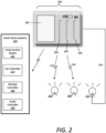
- FIG. 2 illustrates another example of a home device controller, according to various embodiments.
- a home device controller panel 201 includes a screen 202 and multiple touch control grooves 203, 204, 205.
- Home device controller 200 can include a touch control panel 201, and can further include AC electronics as discussed below.
- the home device controller 200 may be mounted in a wall, e.g. of a building such as a home or business.
- the touch control panel 201 may include a removable bezel, e.g. a plastic bezel, that may be snapped on and off of the unit, thereby providing a capability for cosmetic changes, e.g. color changes, without necessitating replacement of the entire touch control panel 201.
- the construction, configuration, and/or operation of the touch control grooves 203, 204, 205 may be as described for the touch control groove 102 shown and described with respect to FIG. 1 .
- multiple simultaneous gestures in a plurality of touch control grooves 203, 204, 205 may be interpreted simultaneously.
- each touch control groove 203, 204, 205 may be a corresponding touch sensor or set of touch sensors (e.g., a capacitive touch slider).
- the touch sliders may be linked together using a bus such as I 2 C or SPI as described herein.
- Each touch slider may be associated with a particular light circuit (e.g., the home device controller 200 may have multiple outputs, each of which can be assigned to a particular touch slider and therefore a particular corresponding touch control groove. Therefore, when the touch controller detects a gesture at a particular touch slider corresponding to a particular touch control groove, the touch controller can transmit a set of signals corresponding to the touch gesture to a microprocessor of the home device controller 200, which can generate a corresponding control command for the circuit corresponding to the touch slider and control groove combination.
- such circuits may be physical circuits (e.g., AC or DC circuits as described above).
- such circuits may be virtual circuits, wired or unwired, and the microprocessor can transmit the control instructions corresponding to the detected gesture, as described above using the applicable network (e.g., WiFi, Zigbee, Z-Wave, DALI, Bluetooth, etc.).
- the applicable network e.g., WiFi, Zigbee, Z-Wave, DALI, Bluetooth, etc.
- software may provide a user interface on screen 202, or via a mobile application on a smartphone or a web site provided by a server, which provides the user with an option to map a particular touch control groove to a particular output, such as a physical lighting circuit connected to the home device controller 200, a physical lighting circuit connected to a different home device controller, or a third party device such as a smart bulb, an audio system, smart blinds or curtains, a thermostat, or a fan.
- the home device controller 200 may be notified and may store a mapping in its memory (e.g.
- non-volatile memory such as flash memory
- the mapping may be consulted, or a state resulting from an earlier consultation of the mapping may be in place, and consequently the device may be controlled accordingly by the gesture in the touch control groove.
- the home device controller 200 can be mounted to replace an existing light switch panel, and can further utilize the existing load and line wires of the gang-box mounted within the wall behind the light switch panel.
- the home device controller 200 can include processing and memory resources as well as network communication modules implementing one or more network communications protocols.
- one or more of the touch control grooves (e.g., control groove 205) can be associated with a wired connection 215 to a home device, such as a light element 235, e.g. via a direct wiring from a load wire attached to the home device controller.
- the home device need not be a smart home device (e.g., including a controller and/or wireless communication module).
- the screen 202 can comprise a touch screen and can enable the user to operate any number of connected smart home systems 220, such as smart light devices 233, 234, a temperature control system 222, a fan controller 224, a window controller 226, or an audio controller 228.
- the user can select a particular smart home device on the touch screen 202 can utilize a touch control groove 203, 204 to turn on/off or adjust a particular adjustable parameter of the selected smart home device.
- the screen 202 itself can behave as a touch control groove, and the user can input gestures thereon to control a selected smart home device in accordance with the description provided herein (for example, using the Y axis reported by the touch screen as the position within a groove for touch gesture recognition as described above).
- gesture recognition may be performed in the presence of other user interface elements being displayed on the screen, such as picture display, motion art display, selectable items such as scenes or devices, etc.
- it may be determined whether the touch comprises a touch control gesture as discussed above. If so, then the appropriate functionality for that gesture may be performed, and if not, then the touch information may be relayed to other processing components for interpretation such as interactions with an on-screen user interface.
- the microprocessor can be triggered to interpret gestures performed on the touch screen 202 as control commands for adjusting the room temperature.
- a touch-scroll gesture upwards on the touch screen 202 can cause the microprocessor to generate commands to increase the temperature of the room, and transmit those temperature control commands to the temperature control system 222.
- a touch control groove (e.g., control groove 203) can act as a dedicated control groove for a particular smart home device (e.g., light element 233).
- the user can perform gestures on the control groove 203, and the microprocessor of the home device controller 200 therein can interpret the gesture, generate control commands for the light element 233 in accordance with the gesture, and transmit the control commands to the light element 233 accordingly.
- a touch control groove (e.g., control groove 204) can comprise a universal control groove 204 that can dynamically change connectivity between the various smart home systems 220 and/or light elements 233, 234 based on user selections from a displayed selectable menu on the screen.
- the microprocessor therein can adaptively alter gesture interpretations for gestures performed on the control groove 204. For example, if the user selects the window controller 226 on the touch screen, the microprocessor can be triggered to interpret gestures performed on the control groove 204 as control commands for an actuator or servo operable to open or close window shades or blinds.
- the touch screen 202 can graphically display dynamic content corresponding to the gestures being performed by the user on the touch screen 202 or a particular control groove 203, 204, 205, such as displaying a dynamic temperature setting, dim value, fan speed, window-shade setting, or volume.
- FIG. 3 is a hardware diagram illustrating a computing device upon which example home device controllers described herein may be implemented.
- the computing device 300 can comprise the logic and processing performed via user interaction with the home device controllers 100, 200 as shown and described with respect to FIGS.1 and 2 .
- the computing device 300, or home controller 300 (used interchangeably) includes processing resources 310, a main memory 320, a read-only memory (ROM) 330, a display 340, and a communication interface 350.
- the computing device 300 includes at least one processor 310 for processing information stored in the main memory 320, such as provided by a random-access memory (RAM) or other dynamic storage device, for storing information and instructions which are executable by the processor 310.
- RAM random-access memory
- the "microcontroller” or “microprocessor” described throughout can comprise the processor 310 or combination of the processor 310 and main memory 320 as shown and described with respect to FIG. 3 .
- the microprocessor may be a general-purpose microprocessor, a microcontroller, a combination of one or more microprocessors and/or microcontrollers acting in concert, and/or a touch sensor specific integrated circuit incorporating, or connected to, one or more of these processing configurations.
- the main memory 320 also may be used for storing temporary variables or other intermediate information during execution of instructions to be executed by the processor 310.
- the computing device 300 may also include the ROM 330 or other static storage device for storing static information and instructions for the processor 310.
- the communication interface 350 enables the computing device 300 to communicate over one or more control networks 380 (e.g., Bluetooth, Zigbee, Wi-Fi, etc.) through use of one or more wireless network links. Using the network links, the computing device 300 can communicate with one or more home devices, one or more servers or third-party intermediary communication module.
- the executable instructions in the memory 320 can include gesture interpretation instructions 322, which the computing device 300 can execute to determine gestures performed by users on a particular control groove or on the display screen 340, and generate control commands for the appropriate home device accordingly.
- the processor 310 can execute the gesture interpretation instructions 322 to receive signals from the sensors 360 coupled to the control groove(s) and/or touch sensors of the display, and generate control commands based on the detected gestures.
- the executable instructions stored in memory 320 can also include control connectivity instructions 324, which the computing device 300 can execute to selectively connect the communication interface 350 to various home devices to transmit the generated control commands by the processor 310 executing the gesture interpretation instructions 322.
- control connectivity instructions 324 which the computing device 300 can execute to selectively connect the communication interface 350 to various home devices to transmit the generated control commands by the processor 310 executing the gesture interpretation instructions 322.
- the computing device 300 may be connected via a wired connection to one or more home devices 370 (e.g., light elements), or can implement wireless network protocols to connect with smart home devices via the control network 380 to transmit he control commands.
- the home controller 300 may be coupled to AC controller 390, for example by clips that provide for an electrical connection to be made between spring clips or pogo pins on one side (e.g., the home controller 300 or the AC controller 390) and electrically conductive pads on the corresponding side.
- AC controller 390 may include connections to wall wiring for line, load, neutral, and/or ground wires, and in some embodiments, may include L1 and L2 outputs for 3-way configurations.
- AC controller 390 may include an AC microcontroller which receives instructions from home controller 300, and which may control field effect transistors, triac(s), and/or other dimming mechanisms, for example as discussed above.
- the AC controller 390 can include a dimming FET 395 connecting the AC controller 390 to a line wire and load wire of existing wiring (e.g., of a light switch).
- the load wire connects the AC controller 390 to the one or more wired home devices 370 (e.g., lights), and the line wire connects the AC controller 390 (an home device controller 300) to a power source 399.
- the processor 310 is configured with software and/or other logic to perform one or more processes, steps and other functions described with implementations, such as described with respect to FIGS. 1-2 , 4 and elsewhere in the present application. Examples described herein are related to the use of the computing device 300 for implementing the techniques described herein. According to one example, those techniques are performed by the computing device 300 in response to the processor 310 executing one or more sequences of one or more instructions contained in the main memory 320. Such instructions may be read into the main memory 320 from another machine-readable medium. Execution of the sequences of instructions contained in the main memory 320 causes the processor 310 to perform the process steps described herein. In alternative implementations, hard-wired circuitry may be used in place of or in combination with software instructions to implement examples described herein. Thus, the examples described are not limited to any specific combination of hardware circuitry and software.
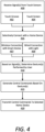
- FIG. 4 is a flow chart describing an example of a method of controlling one or more home devices using a home device controller, according to various implementations.
- FIG. 4 reference may be made to reference characters representing like features as shown and described with respect to FIGS. 1-3 .
- the processes described in connection with FIG. 4 may be performed by a controller or processing resources of an example home device controller 300 of FIG. 3 , which can include the control panels 101, 201 as shown and described with respect to FIGS. 1 and 2 .
- a controller of the home device controller can receive one or more signals from touch sensors (400).
- the touch sensors can be included or operatively coupled to a touch control groove 102 (402) a touch screen 202 of the home device controller (404).
- the controller can selectively connect the home device controller with a home device (405).
- the connection can comprise a wired connection with a light element (409), and/or a wireless connection with a smart home device (407), such as those described throughout the present disclosure.
- the signals can correspond to a user selection from a displayed menu of smart home devices and a gesture performed on one of the touch screen or a touch control groove of the home device controller.
- the controller can determine a gesture performed by the user (410).
- the gesture can comprise a tap gesture, a scroll or swipe gesture (up or down), or a touch-hold and scroll gesture.
- the controller can generate control commands for the connected or selected home device (415), and transmit the control commands to the home device.
- the control commands can comprise dim level commands for a light, audio volume commands, window actuator commands, temperature control commands, fan speed commands, and the like.
Description
- This application claims the benefit of priority to
U.S. Application No. 62/441,871, entitled "Home Control with Capacitive Touch Grooves," filed on January 3, 2017 U.S. Patent No. 15/861,655 . - Home control systems, such as lighting control systems used for lighting fixtures, include binary analog switches and analog dimmer switches that enable users to control one or more lights wired to an electrical box upon which such switches are connected. Control of these switches can be cumbersome and/or unattractive, and it would therefore be useful to have improved means of controlling them.
EP2308270A1 discloses a user interface device for controlling an electrical consumer, in particular, a light system.US2013141009A1 discloses a lighting device and a method for controlling lighting with a lighting controller.US7084859B1 discloses programmable tactile touch screen displays and man-machine interfaces.US2008211779A1 discloses single and multipoint touch screens.US2014253483A1 discloses an in-wall, touch-actuated electronic control device which makes use of gesture motions. - The disclosure herein is illustrated by way of example, and not by way of limitation, in the figures of the accompanying drawings in which like reference numerals refer to similar elements, and in which:
-
FIG. 1 illustrates an example of a home device controller including a touch control panel include a touch control groove, according to various embodiments; -
FIG. 2 illustrates an example of a home device controller including a touch control panel including multiple touch control grooves and a screen, according to various embodiments; -
FIG. 3 is a hardware diagram illustrating an example of a computing device upon which example home device controllers described herein may be implemented; and -
FIG. 4 is a flow chart describing an example of a method of controlling one or more home devices using a home device controller, according to various implementations. - The present invention is defined in the appended independent claims to which reference should be made. Advantageous features are set out in the appended dependent claims.
- Examples of lighting control systems described herein can be implemented in numerous ways, including as a process, an apparatus, a system, a composition of matter, a computer readable medium such as a computer readable storage medium or a computer network wherein program instructions are sent over one or more communication links. In this specification, these implementations, or any other form that examples of implementations may take, may be referred to as techniques. In general, the order of the steps of disclosed processes may be altered within the scope of the embodiments described herein.
- A detailed description of one or more embodiments is provided below. Numerous specific details are set forth in the following description in order to provide a thorough understanding of the described embodiments.
- Among other benefits, the examples described herein achieve a technical effect of utilizing existing home gang-box wiring for light switches to provide a smart home lighting control panel that interconnects (wirelessly and/or wired) to a number of home devices that can then be controlled via the lighting control panel. Examples described herein replace analog light switches with a digital touch panel including one or more touch grooves and/or a touch screen providing advancements in user home experiences.
- As used herein, a home device controller can comprise a computing device and can provide network connectivity and processing resources for communicating with a system of lighting controllers over one or more networks. The home device controller can also correspond to custom hardware, in-vehicle devices, or on-board computers, etc. The computing device can also operate a designated application configured to communicate with a network of home devices.
- One or more examples described herein provide that methods, techniques, and actions performed by a computing device are performed programmatically, or as a computer-implemented method. Programmatically, as used herein, means through the use of code or computer-executable instructions. These instructions can be stored in one or more memory resources of the computing device. A programmatically performed step may or may not be automatic.
- One or more examples described herein can be implemented using programmatic modules, engines, or components. A programmatic module, engine, or component can include a program, a sub-routine, a portion of a program, or a software component or a hardware component capable of performing one or more stated tasks or functions. As used herein, a module or component can exist on a hardware component independently of other modules or components. Alternatively, a module or component can be a shared element or process of other modules, programs or machines.
- Some examples described herein can generally require the use of computing devices, including processing and memory resources. For example, one or more examples described herein may be implemented, in whole or in part, on computing devices. Memory, processing, and network resources may all be used in connection with the establishment, use, or performance of any example described herein (including with the performance of any method or with the implementation of any system).
- Furthermore, one or more examples described herein may be implemented through the use of instructions that are executable by one or more processors. These instructions may be carried on a non-transitory computer-readable medium. Machines shown or described with figures below provide examples of processing resources and computer-readable mediums on which instructions for implementing examples disclosed herein can be carried and/or executed. In particular, the numerous machines shown with examples of the invention include processors and various forms of memory for holding data and instructions. Examples of non-transitory computer-readable mediums include permanent memory storage devices, such as hard drives on personal computers or servers. Other examples of computer storage mediums include portable storage units, such as CD or DVD units, flash memory (such as those carried on smartphones, multifunctional devices or tablet computers), and magnetic memory. Computers, terminals, network enabled devices (e.g., mobile devices or home device controllers described herein) are all examples of machines and devices that utilize processors, memory, and instructions that may be stored on computer-readable mediums. Additionally, examples may be implemented in the form of computer-programs, or a computer usable carrier medium capable of carrying such a program.
-
FIG. 1 illustrates an example of a home device controller including a touch groove control panel, according to various embodiments. The example shown inFIG. 1 is a frontal view of thehome device controller 100 that includestouch control panel 101. According to one or more examples, ahome device controller 100 may provide the capability for a user to control lighting levels. In some embodiments,touch control panel 101 may be the size of a Decora switch (e.g. 1.31 x 2.63 inches) and may fit inside a standard Decora light switch cover. In some embodiments,home device controller 100 may be the size of a standard, midway, or jumbo light switch cover. In some embodiments, the forward-facing layer ofhome device controller 100 may be a single piece of nonconductive material such as plastic (including nylon, polycarbonate, ABS, etc.), which in some embodiments may be injection molded.Touch control panel 101 may be a component of ahome device controller 100 that includes AC electronics as discussed below, and may be mounted in a wall, e.g. of a building such as a home or business. - A
control groove 102, ortouch control groove 102, can be formed on thetouch control panel 101 of thehome device controller 100 and may provide the capability to adjust lighting or control functions other devices. A touch sensor, such as a capacitive touch sensor or a combination of a plurality of capacitive touch sensors, may be placed underneath or otherwise coupled to thecontrol groove 102. For example, the touch sensor may be embedded in a printed circuit board (e.g., made of glass-reinforced epoxy laminate sheets, such as FR4) or in polyimide film such as Kapton, which in some embodiments may be integrated with a flex connector. - The touch sensor may be configured to perform in a "slider" configuration, examples of which are discussed in Atmel Corporation document number QTAN0079, "Buttons, Sliders, and Wheels: Sensor Design Guide," available via the Internet from Atmel. Further details are available in Paul Russel, "Atmel QTouch Layout Quick Reference," available via the Internet from Atmel. Touch sensor configurations may be implemented utilizing any combination of capacitive touch sensors, such as CapTIvate™ capacitive touch sensor technology developed by Texas Instruments, examples of which are discussed in "CapTIvate Technology Guide," in the section entitled "Design Guide," available via the Internet from Texas Instruments. In some embodiments, a touch sensor may be configured as a "Mutual Capacitive Slider" as specified therein in the "Sliders and Wheels" chapter.
- In certain examples, the touch sensor can comprise a capacitive touch slider, such as a planar or non-planar, self-capacitance or mutual capacitance, interdigitated X and Y electrodes, or flooded-X capacitive slider, and may be implemented behind the
control groove 102. The touch sensor is connected to a touch controller. The touch controller can be a microcontroller such as an Atmel ATTiny, Texas Instruments MSP430 or a dedicated touch controller such as a Silicon Labs TouchXpress. The touch controller analyzes the capacitance of the touch sensor and generates digital or analog signals. Signals from the touch controller may be transmitted to a microprocessor, for example, using a Universal Asynchronous Receiver/Transmitter (UART), Inter-Integrated Circuit (I2C, specifications of which are available from NXP Semiconductors as document number UM10204, "I2C-bus specification and user manual," available via the Internet from NXP), or Serial Peripheral Interface bus (SPI, details of which are available from Byte Paradigm in their article available over the Internet entitled "Introduction to I2C and SPI protocols"). - In some embodiments, the
control groove 102 may be between 60mm and 80mm in length, and may be horizontally sized for comfort using a typical finger (e.g., between 10mm and 20mm in width). The depth of thecontrol groove 102 may be any dimension that provides visual and/or tactile indication of its location (e.g., between 1mm and 10mm). In some embodiments (e.g., where depth is at a premium), the depth may be between 1mm and 3.5mm (e.g., approximately 2.5mm). - The material (e.g., plastic) at the basin (e.g., the maximum depth) of the
control groove 102 may be relatively thin to optimize the sensitivity of the touch sensors behind the control groove 102 (e.g., between 0.25mm and 2mm). In some embodiments, the touch sensors may be bonded to a back portion of thehome device controller 100 that comprises thecontrol groove 102, or can be incorporated into thecontrol groove 102. In some embodiments, the touch sensors may be behind thetouch control groove 102 on a printed circuit board (PCB) (e.g., an FR4 PCB), or a Kapton film, such that there is little or no air gap therebetween (e.g. less than 2mm). In some embodiments, the touch sensors may be mounted to an elastic material such as a foam, which may press the touch sensors against the back of thecontrol groove 102 to eliminate any potential air gap. - A home device controller can include lighting control capability that may be integrated into the same module. For example, a home device controller can function as an AC dimmer, which commonly dims a light by chopping up or otherwise manipulating the output AC waveform on the "load" line going to a light by eliminating some portion of the output, relative to the input "line" AC, during a phase of the duty cycle (e.g., a "leading edge" or "trailing edge" dimmer which may chop out a part of the waveform either before or after zero crossings), resulting in a duty cycle that indicates the desired amount of dimming. In various embodiments, the
home device controller 101 can perform such dimming using a triac or a field-effect transistor (FET), such as a MOSFET (e.g., a pair of FETs and/or MOSFETs), which may be under the control of a microcontroller or touch controller (e.g., an Atmel ATTiny or ATMega) that receives instructions on a desired on/off/dimming level state and adjusts its outputs accordingly. - In some embodiments, a home device controller may utilize DC power for lighting (e.g., 10V, 12V, or 24V) in which the output voltage may be varied. In some embodiments, the home device controller can utilize a Digital Addressable Lighting Interface (DALI) for controlling a light, for example, as discussed in technical standards IEC 62386 and IEC 60929. In some embodiments, the home device controller can transmit lighting control commands, corresponding to a specified on/off/dimming state, based on touch gestures on the
control groove 102 using a wireless network such as WiFi, Zigbee, Z-Wave, or Bluetooth (including BLE). - Touch gestures may be performed by a user in the
control groove 102, and interpreted by the microprocessor to generate the lighting control commands. In particular, one-dimensional touch gestures such as taps, flicks, and slides may be detected. The microprocessor can detect touch gestures by analyzing the signals corresponding to gestures performed on thetouch control groove 102. The signals can be received by the microprocessor over a specific interface (e.g., UART, I2C, SPI, etc. as described above) used for communication between the touch controller(s) and the microprocessor. At the microprocessor (which in some embodiments may be a general-purpose microprocessor, and in some embodiments may be a microcontroller, and in some embodiments may be a combination of one or more microprocessors and/or microcontrollers acting in concert, and in some embodiments, may be a touch sensor specific integrated circuit incorporating, or connected to, one or more of these processing configurations), the signals may be interpreted to determine positions and times at which a finger is detected (or ceases to be detected), and from which the microprocessor can calculate touch velocities, accelerations, touch pressure, and touch position on thecontrol groove 102. The microprocessor can combine the touch positions, times, velocities, etc. to derive gestures can generate corresponding control commands for connected lighting devices or other home devices. In some embodiments, machine learning techniques may be applied to create gesture recognizer models using training data of touch gestures and corresponding classifications, e.g. from a plurality of people. Examples of such training are provided in Hao Lu and Yang Li, "Gesture Coder: A Tool for Programming Multi-Touch Gestures by Demonstration," published in the Proceedings of the SIGCHI Conference on Human Factors in Computing Systems 2012, pages 2875-2884, and available over the Internet from Google Research; and in Daniel Wood, "Methods for Multi-Touch Gesture Recognition," published in the Proceedings of the 20th Annual ACM Symposium on User Interface Software and Technology (2007), both of which are included herein by reference for all purposes as if set forth in full. Examples of suitable machine learning techniques are well known to those in the art and include generation of state machines, Hidden Markov Models, Support Vector Machines, Bayesian Networks, Artificial Neural Networks, and Dynamic Time Warping. - Examples of such gestures a user can perform on the
control groove 102, in which examples of how to detect such gestures are provided by way of illustration, in which an illustrative implementation is presumed to provide values of 0-1000 indicating where along a touch groove or area a finger is detected, with 0 being at the bottom, this example being purely illustrative, and for example interpretable in percentage terms, as those skilled in the art will readily appreciate, can include: - Tap - which in some illustrative embodiments may be implemented by detecting a finger's presence in the groove, followed by detection of its absence, with a change of less than 10.
- Flick up (quick movement) - which in some illustrative embodiments may be implemented by detecting that a finger is in contact for less than 300ms, with its final point of contact determined to be between 10 and 100 greater than the initial point of contact.
- Flick down (quick movement) - which in some illustrative embodiments may be implemented by detecting that a finger is in contact for less than 300ms, with its final point of contact determined to be between 10 and 100 less than the initial point of contact.
- Swipe up (slower than flick) - which in some illustrative embodiments may be implemented by detecting that a finger is in contact for at least 300ms and/or travels a distance of at least 100, and has a point of contact that increases over time relative to the initial point of contact. In some embodiments, when a swipe up is detected, values may be incrementally provided as they change, for example to facilitate interactive dimming, volume adjustment, or other forms of control. In some embodiments, a swipe up may become a swipe down, enabling bidirectional adjustments, by detecting that the point of contact has begin to decrease over time relative to its previous point(s) of contact.
- Swipe down (slower than flick) - which in some illustrative embodiments may be implemented by detecting that a finger is in contact for at least 300ms and/or travels a distance of at least 100, and has a point of contact that decreases over time relative to the initial point of contact. In some embodiments, when a swipe up is detected, values may be incrementally provided as they change, for example to facilitate interactive dimming, volume adjustment, or other forms of control. In some embodiments, a swipe down may become a swipe up, enabling bidirectional adjustments, by detecting that the point of contact has begin to increase over time relative to its previous point(s) of contact.
- Hold and move up - which in some illustrative embodiments may be implemented as described above for Swipe up, with the initial contact triggering detection.
- Hold and move down - which in some illustrative embodiments may be implemented as described above for Swipe down, with the initial contact triggering detection.
- Palm detection - which in some illustrative embodiments may be implemented as detecting presence of touch over a width too large to correspond to a human finger (e.g. 20mm), which in some embodiments may cause the event to be ignored as unintentional.
- In some embodiments, the microcontroller can interpret a hold and move gesture in the same manner as a swipe gesture. Gestures may be mapped to lighting control actions, for example as follows:
Gesture Action Tap Toggle on/off Flick up On (in various embodiments, to last "on" dimming level, to maximum, and/or to preset level) Flick down Off Swipe up/Hold & move/slow swipe up Interactively adjust dim level corresponding to movement (up = higher light level, down = lower light level). This may begin from the current dim level (i.e. when the light is "on" when the gesture is recognized) or from the minimum dim level (i.e. when the light is "off" at the time the gesture is recognized) Swipe down/Hold & move/slow swipe down Interactively adjust dim level corresponding to movement (up = higher light level, down = lower light level). This may begin from the current dim level. - In various examples, the microcontroller or touch controller can assign numerical values to the dimming level of lights in a predetermined range 0...n, where 0 represents "off" and n represents a maximum value. On/off lights such as lights that are not dimmable or are otherwise configured not to be dimmed may have n=1 in some embodiments, or may use the same maximum value as an unrestricted dimmable light in some embodiments. The microcontroller can transmit the assigned numerical value to a module that sets the output level of the light. In various embodiments, the module can comprise a logical component of the same microprocessor, or can comprise a different microprocessor.
- In some embodiments, lights may be calibrated to have a minimum and/or maximum dim value. The maximum dim value can correspond to a maximum brightness to which the light may be interactively dimmed. The minimum dim value can correspond to a minimum brightness "on" value to which the light can be dimmed (e.g., any increase in the dim level from a 0 "off" value may incur immediately setting the dim level to the minimum dim level, which may be adjusted upward therefrom, and any decrease in the dim level from the minimum level may incur immediately setting the dim level to a 0 "off" value).
- The type of controllers used illustratively herein may be used for controlling other devices than lighting, which may in some embodiments be accomplished with the same gestures. For example, a fan may be turned on/off or have a spin level set, shades or blinds may be raised and lowered or drawn and undrawn, temperature may be set for a climate control system such as a thermostat, etc.
- According to examples shown in
FIG. 1 , thehome device controller 101 can be configured to operate one ormore lights control groove 102, which the microprocessor of thehome device controller 101 can interpret to control an on/off state and/or a dim level of the light(s) 110, 115. In various examples, thehome device controller 101 can be configured to replace an existing light switch utilizing the same wiring as the light switch. In certain implementations, thehome device controller 101 can interpret the gestures to generate light control commands for a light 115 using awired connection 113, and/or for a light 110 (e.g., a smart bulb) using a wireless connection 112 (e.g., using WiFi, Zigbee, Z-Wave, or Bluetooth). - In some examples, the
home device controller 101 can be connected (wirelessly or wired) to a smart-home device 120, such as an audio system, a fan, a temperature control system, or automatically controlled curtains or blinds. The microprocessor can interpret gestures performed on thecontrol groove 102 to turn on/off and adjust, for example, the fan speed of a fan, the volume of an audio system, the room temperature, an open, closed or intermediate state of curtains, shades, or blinds, and the like. -
FIG. 2 illustrates another example of a home device controller, according to various embodiments. Referring toFIG. 2 , a homedevice controller panel 201 includes ascreen 202 and multipletouch control grooves Home device controller 200 can include atouch control panel 201, and can further include AC electronics as discussed below. Thehome device controller 200 may be mounted in a wall, e.g. of a building such as a home or business. In some embodiments, thetouch control panel 201 may include a removable bezel, e.g. a plastic bezel, that may be snapped on and off of the unit, thereby providing a capability for cosmetic changes, e.g. color changes, without necessitating replacement of the entiretouch control panel 201. - The construction, configuration, and/or operation of the
touch control grooves touch control groove 102 shown and described with respect toFIG. 1 . In some embodiments, multiple simultaneous gestures in a plurality oftouch control grooves - Connected to otherwise coupled to each
touch control groove - Each touch slider may be associated with a particular light circuit (e.g., the
home device controller 200 may have multiple outputs, each of which can be assigned to a particular touch slider and therefore a particular corresponding touch control groove. Therefore, when the touch controller detects a gesture at a particular touch slider corresponding to a particular touch control groove, the touch controller can transmit a set of signals corresponding to the touch gesture to a microprocessor of thehome device controller 200, which can generate a corresponding control command for the circuit corresponding to the touch slider and control groove combination. In some embodiments, such circuits may be physical circuits (e.g., AC or DC circuits as described above). In some embodiments, such circuits may be virtual circuits, wired or unwired, and the microprocessor can transmit the control instructions corresponding to the detected gesture, as described above using the applicable network (e.g., WiFi, Zigbee, Z-Wave, DALI, Bluetooth, etc.). - In an illustrative embodiment, software may provide a user interface on
screen 202, or via a mobile application on a smartphone or a web site provided by a server, which provides the user with an option to map a particular touch control groove to a particular output, such as a physical lighting circuit connected to thehome device controller 200, a physical lighting circuit connected to a different home device controller, or a third party device such as a smart bulb, an audio system, smart blinds or curtains, a thermostat, or a fan. When a device is selected to be mapped to a touch control groove, thehome device controller 200 may be notified and may store a mapping in its memory (e.g. in non-volatile memory such as flash memory) that associates the device with an identifier associated with the touch control groove. Subsequently, when a gesture is detected in the touch control groove, the mapping may be consulted, or a state resulting from an earlier consultation of the mapping may be in place, and consequently the device may be controlled accordingly by the gesture in the touch control groove. - In the example shown in
FIG. 2 , thehome device controller 200 can be mounted to replace an existing light switch panel, and can further utilize the existing load and line wires of the gang-box mounted within the wall behind the light switch panel. Thehome device controller 200 can include processing and memory resources as well as network communication modules implementing one or more network communications protocols. In certain aspects, one or more of the touch control grooves (e.g., control groove 205) can be associated with awired connection 215 to a home device, such as alight element 235, e.g. via a direct wiring from a load wire attached to the home device controller. For such wired connections, the home device need not be a smart home device (e.g., including a controller and/or wireless communication module). - According to various examples, the
screen 202 can comprise a touch screen and can enable the user to operate any number of connectedsmart home systems 220, such as smartlight devices fan controller 224, awindow controller 226, or an audio controller 228. In certain implementations, the user can select a particular smart home device on thetouch screen 202 can utilize atouch control groove screen 202 itself can behave as a touch control groove, and the user can input gestures thereon to control a selected smart home device in accordance with the description provided herein (for example, using the Y axis reported by the touch screen as the position within a groove for touch gesture recognition as described above). In such embodiments, gesture recognition may be performed in the presence of other user interface elements being displayed on the screen, such as picture display, motion art display, selectable items such as scenes or devices, etc. In such embodiments, when a touch on the screen is detected, it may be determined whether the touch comprises a touch control gesture as discussed above. If so, then the appropriate functionality for that gesture may be performed, and if not, then the touch information may be relayed to other processing components for interpretation such as interactions with an on-screen user interface. - For example, if the user selects the temperature control system 222 on a displayed selectable menu on the
touch screen 202, the microprocessor can be triggered to interpret gestures performed on thetouch screen 202 as control commands for adjusting the room temperature. Thus, a touch-scroll gesture upwards on thetouch screen 202 can cause the microprocessor to generate commands to increase the temperature of the room, and transmit those temperature control commands to the temperature control system 222. - In certain implementations, a touch control groove (e.g., control groove 203) can act as a dedicated control groove for a particular smart home device (e.g., light element 233). In such implementations, the user can perform gestures on the
control groove 203, and the microprocessor of thehome device controller 200 therein can interpret the gesture, generate control commands for thelight element 233 in accordance with the gesture, and transmit the control commands to thelight element 233 accordingly. - In variations, a touch control groove (e.g., control groove 204) can comprise a
universal control groove 204 that can dynamically change connectivity between the varioussmart home systems 220 and/orlight elements control groove 204. For example, if the user selects thewindow controller 226 on the touch screen, the microprocessor can be triggered to interpret gestures performed on thecontrol groove 204 as control commands for an actuator or servo operable to open or close window shades or blinds. - In further implementations, the
touch screen 202 can graphically display dynamic content corresponding to the gestures being performed by the user on thetouch screen 202 or aparticular control groove - The utilization of three
touch control grooves FIG. 2 is purely illustrative, and it is contemplated that the same techniques described herein may be implemented for 2, 4, 5, 6, or more touch control grooves (and corresponding touch sliders). -
FIG. 3 is a hardware diagram illustrating a computing device upon which example home device controllers described herein may be implemented. For example, thecomputing device 300 can comprise the logic and processing performed via user interaction with thehome device controllers FIGS.1 and2 . In one implementation, thecomputing device 300, or home controller 300 (used interchangeably) includesprocessing resources 310, amain memory 320, a read-only memory (ROM) 330, adisplay 340, and acommunication interface 350. Thecomputing device 300 includes at least oneprocessor 310 for processing information stored in themain memory 320, such as provided by a random-access memory (RAM) or other dynamic storage device, for storing information and instructions which are executable by theprocessor 310. As provided herein, the "microcontroller" or "microprocessor" described throughout can comprise theprocessor 310 or combination of theprocessor 310 andmain memory 320 as shown and described with respect toFIG. 3 . In various embodiments, the microprocessor may be a general-purpose microprocessor, a microcontroller, a combination of one or more microprocessors and/or microcontrollers acting in concert, and/or a touch sensor specific integrated circuit incorporating, or connected to, one or more of these processing configurations. Themain memory 320 also may be used for storing temporary variables or other intermediate information during execution of instructions to be executed by theprocessor 310. Thecomputing device 300 may also include theROM 330 or other static storage device for storing static information and instructions for theprocessor 310. - The
communication interface 350 enables thecomputing device 300 to communicate over one or more control networks 380 (e.g., Bluetooth, Zigbee, Wi-Fi, etc.) through use of one or more wireless network links. Using the network links, thecomputing device 300 can communicate with one or more home devices, one or more servers or third-party intermediary communication module. The executable instructions in thememory 320 can includegesture interpretation instructions 322, which thecomputing device 300 can execute to determine gestures performed by users on a particular control groove or on thedisplay screen 340, and generate control commands for the appropriate home device accordingly. For example, theprocessor 310 can execute thegesture interpretation instructions 322 to receive signals from thesensors 360 coupled to the control groove(s) and/or touch sensors of the display, and generate control commands based on the detected gestures. - The executable instructions stored in
memory 320 can also includecontrol connectivity instructions 324, which thecomputing device 300 can execute to selectively connect thecommunication interface 350 to various home devices to transmit the generated control commands by theprocessor 310 executing thegesture interpretation instructions 322. As described herein thecomputing device 300 may be connected via a wired connection to one or more home devices 370 (e.g., light elements), or can implement wireless network protocols to connect with smart home devices via thecontrol network 380 to transmit he control commands. - In some embodiments, the
home controller 300 may be coupled toAC controller 390, for example by clips that provide for an electrical connection to be made between spring clips or pogo pins on one side (e.g., thehome controller 300 or the AC controller 390) and electrically conductive pads on the corresponding side.AC controller 390 may include connections to wall wiring for line, load, neutral, and/or ground wires, and in some embodiments, may include L1 and L2 outputs for 3-way configurations. In some embodiments,AC controller 390 may include an AC microcontroller which receives instructions fromhome controller 300, and which may control field effect transistors, triac(s), and/or other dimming mechanisms, for example as discussed above. In certain examples, theAC controller 390 can include adimming FET 395 connecting theAC controller 390 to a line wire and load wire of existing wiring (e.g., of a light switch). In the example shown inFIG. 3 , the load wire connects theAC controller 390 to the one or more wired home devices 370 (e.g., lights), and the line wire connects the AC controller 390 (an home device controller 300) to apower source 399. - The
processor 310 is configured with software and/or other logic to perform one or more processes, steps and other functions described with implementations, such as described with respect toFIGS. 1-2 ,4 and elsewhere in the present application. Examples described herein are related to the use of thecomputing device 300 for implementing the techniques described herein. According to one example, those techniques are performed by thecomputing device 300 in response to theprocessor 310 executing one or more sequences of one or more instructions contained in themain memory 320. Such instructions may be read into themain memory 320 from another machine-readable medium. Execution of the sequences of instructions contained in themain memory 320 causes theprocessor 310 to perform the process steps described herein. In alternative implementations, hard-wired circuitry may be used in place of or in combination with software instructions to implement examples described herein. Thus, the examples described are not limited to any specific combination of hardware circuitry and software. -
FIG. 4 is a flow chart describing an example of a method of controlling one or more home devices using a home device controller, according to various implementations. In the below description ofFIG. 4 , reference may be made to reference characters representing like features as shown and described with respect toFIGS. 1-3 . Furthermore, the processes described in connection withFIG. 4 may be performed by a controller or processing resources of an examplehome device controller 300 ofFIG. 3 , which can include thecontrol panels FIGS. 1 and2 . - Referring to
FIG. 4 , a controller of the home device controller can receive one or more signals from touch sensors (400). The touch sensors can be included or operatively coupled to a touch control groove 102 (402) atouch screen 202 of the home device controller (404). In various examples, the controller can selectively connect the home device controller with a home device (405). In certain aspects, the connection can comprise a wired connection with a light element (409), and/or a wireless connection with a smart home device (407), such as those described throughout the present disclosure. In one example, the signals can correspond to a user selection from a displayed menu of smart home devices and a gesture performed on one of the touch screen or a touch control groove of the home device controller. - Based on the received signals, the controller can determine a gesture performed by the user (410). As described herein, the gesture can comprise a tap gesture, a scroll or swipe gesture (up or down), or a touch-hold and scroll gesture. Based on the gesture, the controller can generate control commands for the connected or selected home device (415), and transmit the control commands to the home device. As described herein, the control commands can comprise dim level commands for a light, audio volume commands, window actuator commands, temperature control commands, fan speed commands, and the like.
- It is contemplated for examples described herein to extend to individual elements and concepts described herein, independently of other concepts, ideas or systems, as well as for examples to include combinations of elements recited anywhere in this application. Although examples are described in detail herein with reference to the accompanying drawings, it is to be understood that the concepts are not limited to those precise examples. Accordingly, it is intended that the scope of the concepts be defined by the following claims.
Claims (11)
- A home device controller (200) comprising:a touch screen (202) configured to display a selectable menu listing one or more home devices;a wireless communication interface configured to communicate, over one or more wireless networks, with one or more home devices;a wired interface coupled to one or more light elements (233, 234, 235);one or more touch grooves (202, 204, 205) disposed adjacent to the touch screen (202), wherein each of the one or more touch grooves (202, 204, 205) comprises a length and a depth to facilitate a finger of a user in operating the touch groove;one or more touch sliders each being operatively coupled to a corresponding touch groove of the one or more touch grooves (202, 204, 205); andone or more processors executing instructions that cause the home device controller (200) to:receive signals from each respective touch slider of the one or more touch sliders, the signals corresponding to a touch gesture performed by a user interacting with the touch groove (202, 204, 205) corresponding to the respective touch slider;based at least in part on the signals, generate control commands executable by a first home device of the one or more home devices or the one or more light elements (233, 234, 235);transmit the control commands to the first home device for execution;receive a user input on the touch screen (202) selecting a second home device of the one or more home devices wirelessly connected to the home device controller (200);in response to the user input, reconfigure a selected touch groove of the one or more touch grooves (202, 204, 205) to enable wireless control of the second home device using the selected touch groove;subsequent to reconfiguring the selected touch groove, receive signals corresponding to a user gesture performed at any location on the touch screen (202);determine whether the user gesture comprises a touch control gesture or a home device selection gesture;when the user gesture comprises a touch control gesture (i) generate a set of control commands for the second home device based on the received signals corresponding to the user gesture performed on the touch screen (202), and (ii) transmit, over the one or more wireless networks, the set of control commands to the second home device for execution; andwhen the user gesture comprises a home device selection gesture, reconfigure the selected touch groove to enable control of a home device that corresponds to the home device selection gesture.
- The home device controller (200) of claim 1, wherein the first home device comprises a light element from the one or more light elements (233, 234, 235), and wherein the control commands comprise a dim level command to increase or decrease a brightness of the light element.
- The home device controller (200) of claim 2, wherein the executed instructions cause the home device controller (200) to transmit the dim level command as a manipulated output waveform on a load line to the light element.
- The home device controller (200) of claim 2,
wherein the second home device comprises a second light element wirelessly connected to the home device controller (200), and wherein the executed instructions cause the home device controller (200) to transmit the dim level command to the second light element via the wireless communication interface. - The home device controller (200) of claim 1, wherein the second home device comprises one of a temperature control system, a fan controller, a window controller, or an audio controller.
- The home device controller (200) of claim 1, wherein the touch slider comprises a plurality of capacitive touch sensors.
- A non-transitory computer readable medium storing instructions which,
when executed by one or more processors of a home device controller (200), cause the home device controller (200) to:receive signals from a touch slider of the home device controller (200), the signals corresponding to a touch gesture performed by a user interacting with a touch groove of the home device controller (200), wherein the touch groove comprises a length and a depth to facilitate a finger of the user in operating the touch groove;based at least in part on the signals, generate control commands executable by a first home device of either (i) one or more home devices in communication, over one or more wireless networks, with a wireless communication interface of the home device controller (200), or (ii) one or more light elements (233, 234, 235) coupled to a wired interface of the home device controller (200);transmit the control commands to the first home device for execution;receive a user input on a touch screen (202) of the home device controller (200), the user input selecting a second home device of the one or more home devices wirelessly connected to the home device controller (200), wherein the touch screen (202) is disposed adjacent to the touch groove of the home device controller (200);in response to the user input, reconfigure the touch groove to enable wireless control of the second home device using the touch groove;subsequent to reconfiguring the touch groove, receive signals corresponding to a user gesture performed at any location on the touch screen (202);determine whether the user gesture comprises a touch control gesture or a home device selection gesture;when the user gesture comprises a touch control gesture, (i) generate a set of control commands for the second home device based on the received signals corresponding to the user gesture performed on the touch screen (202), and (ii) transmit, over the one or more wireless networks, the set of control commands to the second home device for execution; andwhen the user gesture comprises a home device selection gesture, reconfigure the selected touch groove to enable control of a home device that corresponds to the home device selection gesture. - The non-transitory computer readable medium of claim 7, wherein the first home device comprises a light element from the one or more light elements (233, 234, 235), and wherein the control command comprises a dim level command to increase or decrease a brightness of the light element.
- The non-transitory computer readable medium of claim 8, wherein the executed instructions cause the home device controller (200) to transmit the dim level command as a manipulated output waveform on a load line to the light element.
- The non-transitory computer readable medium of claim 8, wherein the second home device controller (200)comprises a light element wirelessly connected to the home device controller (200), and wherein the executed instructions cause the home device controller (200) to transmit the dim level command to the light element via the wireless communication interface.
- A computer-implemented method of controlling home devices, the method being performed by one or more processors of a home device controller (200) and comprising the steps of:receiving signals from a touch sensor of the home device controller (200), the signals corresponding to a touch gesture performed by a user interacting with a touch groove of the home device controller (200), wherein the touch groove comprises a length and a depth to facilitate a finger of the user in operating the touch groove;based at least in part on the signals, generating control commands executable by a first home device of either (i) one or more home devices in communication, over one or more wireless networks, with a wireless communication interface of the home device controller (200), or (ii) one or more light elements (233, 234, 235) coupled to a wired interface of the home device controller (200);transmitting the control commands to the first home device for execution;receiving a user input on a touch screen (202) of the home device controller (200), the user input selecting a second home device of the one or more home devices wirelessly connected to the home device controller (200), wherein the touch screen (202) is disposed adjacent to the touch groove of the home device controller (200);in response to the user input, reconfiguring the touch groove to enable wireless control of the second home device using the touch groove;subsequent to reconfiguring the touch groove, receiving signals corresponding to a user gesture performed at any location on the touch screen (202);determining whether the user gesture comprises a touch control gesture or a home device selection gesture;when the user gesture comprises a touch control gesture, generating a set of control commands for the second home device based on the received signals corresponding to the user gesture performed on the touch screen (202), and transmitting, over the one or more wireless networks, the set of control commands to the second home device for execution; andwhen the user gesture comprises a home device selection gesture, reconfigure the selected touch groove to enable control of a home device that corresponds to the home device selection gesture.
Applications Claiming Priority (2)
| Application Number | Priority Date | Filing Date | Title |
|---|---|---|---|
| US201762441871P | 2017-01-03 | 2017-01-03 | |
| PCT/US2018/012273 WO2018129105A1 (en) | 2017-01-03 | 2018-01-03 | Home device controller with a touch control groove |
Publications (4)
| Publication Number | Publication Date |
|---|---|
| EP3566114A1 EP3566114A1 (en) | 2019-11-13 |
| EP3566114A4 EP3566114A4 (en) | 2020-09-09 |
| EP3566114B1 true EP3566114B1 (en) | 2023-06-07 |
| EP3566114C0 EP3566114C0 (en) | 2023-06-07 |
Family
ID=62712114
Family Applications (1)
| Application Number | Title | Priority Date | Filing Date |
|---|---|---|---|
| EP18735783.5A Active EP3566114B1 (en) | 2017-01-03 | 2018-01-03 | Home device controller with a touch control groove |
Country Status (6)
| Country | Link |
|---|---|
| US (2) | US11563595B2 (en) |
| EP (1) | EP3566114B1 (en) |
| JP (1) | JP7128840B2 (en) |
| CN (1) | CN110268371B (en) |
| CA (1) | CA3049120A1 (en) |
| WO (1) | WO2018129105A1 (en) |
Families Citing this family (23)
| Publication number | Priority date | Publication date | Assignee | Title |
|---|---|---|---|---|
| USD886749S1 (en) * | 2017-01-03 | 2020-06-09 | Brilliant Home Technology, Inc. | Touch control panel with groove |
| KR20190041632A (en) * | 2017-10-13 | 2019-04-23 | 현대자동차주식회사 | Vehicle and control method of the same |
| US11057238B2 (en) | 2018-01-08 | 2021-07-06 | Brilliant Home Technology, Inc. | Automatic scene creation using home device control |
| USD944216S1 (en) | 2018-01-08 | 2022-02-22 | Brilliant Home Technology, Inc. | Control panel with sensor area |
| US10608836B2 (en) * | 2018-04-09 | 2020-03-31 | MobileM2M Incorporated | Tailoring the availability of network resources to on-demand, user proximity, and schedule time |
| US10985972B2 (en) | 2018-07-20 | 2021-04-20 | Brilliant Home Technoloy, Inc. | Distributed system of home device controllers |
| CN109783707A (en) * | 2019-01-23 | 2019-05-21 | 欧普照明股份有限公司 | A kind of moade setting method and device of monitoring system |
| JP7275854B2 (en) * | 2019-05-23 | 2023-05-18 | 三菱電機株式会社 | remote control device |
| KR20190104101A (en) * | 2019-08-19 | 2019-09-06 | 엘지전자 주식회사 | Method, device, and system for determining a false touch on a touch screen of an electronic device |
| USD945973S1 (en) | 2019-09-04 | 2022-03-15 | Brilliant Home Technology, Inc. | Touch control panel with moveable shutter |
| JP2022548012A (en) * | 2019-09-11 | 2022-11-16 | サバント システムズ インコーポレイテッド | Redundant control of wireless devices in home automation systems |
| USD931239S1 (en) * | 2019-09-26 | 2021-09-21 | Frank Dibartolo | Electrical panel display |
| USD911983S1 (en) * | 2019-10-17 | 2021-03-02 | Shenzehn Cuco Smart Technology Co., Ltd | Switch for smart ceiling fan light |
| US11715943B2 (en) | 2020-01-05 | 2023-08-01 | Brilliant Home Technology, Inc. | Faceplate for multi-sensor control device |
| US11528028B2 (en) | 2020-01-05 | 2022-12-13 | Brilliant Home Technology, Inc. | Touch-based control device to detect touch input without blind spots |
| US11469916B2 (en) * | 2020-01-05 | 2022-10-11 | Brilliant Home Technology, Inc. | Bridging mesh device controller for implementing a scene |
| US11507217B2 (en) | 2020-01-05 | 2022-11-22 | Brilliant Home Technology, Inc. | Touch-based control device |
| US11005247B1 (en) | 2020-11-11 | 2021-05-11 | JPoint Innovation LLC | Junction box interface chassis and pluggable modular devices |
| CN112286122A (en) * | 2020-11-30 | 2021-01-29 | 捷开通讯(深圳)有限公司 | Intelligent household control method, device, terminal and storage medium |
| USD953279S1 (en) * | 2020-12-28 | 2022-05-31 | Crestron Electronics, Inc. | Wall mounted button panel |
| USD975031S1 (en) * | 2021-03-12 | 2023-01-10 | Honeywell International Inc. | Building controller |
| CN113156827B (en) * | 2021-04-02 | 2023-06-20 | 中国科学院计算技术研究所 | Intelligent device control method and system based on semantics |
| CN114466484A (en) * | 2021-12-31 | 2022-05-10 | 珠海雷特科技股份有限公司 | Dimming method and system based on gesture control |
Family Cites Families (196)
| Publication number | Priority date | Publication date | Assignee | Title |
|---|---|---|---|---|
| US4246494A (en) | 1978-12-12 | 1981-01-20 | National Electric Corporation | Digital touch controlled dimmer switch |
| USD283404S (en) | 1983-03-11 | 1986-04-15 | Heiler Matthew J | Color test chart for video systems |
| US4591765A (en) | 1983-10-31 | 1986-05-27 | Beck Gregory M | Lamp control |
| USD288921S (en) | 1984-08-02 | 1987-03-24 | Kohler Co. | Control panel face plate |
| USD308045S (en) | 1987-05-06 | 1990-05-22 | Prescolite Inc. | Combined face plate and control operators for an electrical switch or similar articles |
| USD312974S (en) | 1988-06-20 | 1990-12-18 | Naiad Company | Front panel for a water temperature controller |
| USD319429S (en) | 1988-09-30 | 1991-08-27 | Lutron Electronics Co., Inc. | Wall-mounted lighting control panel |
| USD322606S (en) | 1989-08-22 | 1991-12-24 | Burle Industries (UK) Ltd. | Electronic control keyboard |
| USD346591S (en) | 1991-12-17 | 1994-05-03 | Samsung Electronics Co., Ltd. | Portable pen computer |
| USD364141S (en) | 1992-03-31 | 1995-11-14 | Lutron Electronics Co., Inc. | Combined bezel and actuator for dimmer switch |
| USD343381S (en) | 1992-04-22 | 1994-01-18 | Canon Kabushiki Kaisha | Combined battery and battery charger for a cordless facsimile machine |
| USD344684S (en) | 1992-08-17 | 1994-03-01 | Honeywell Inc. | Multi-purpose user interface panel |
| US7084859B1 (en) * | 1992-09-18 | 2006-08-01 | Pryor Timothy R | Programmable tactile touch screen displays and man-machine interfaces for improved vehicle instrumentation and telematics |
| US5336979A (en) | 1992-11-12 | 1994-08-09 | Leviton Manufacturing Co., Inc. | Microprocessor based touch dimmer system to control the brightness of one or more electric lamps using single or multi-key devices |
| USD360235S (en) | 1993-10-18 | 1995-07-11 | Interactive Network Limited | Game control unit |
| USD362252S (en) | 1993-11-02 | 1995-09-12 | International Business Machines Corporation | Computerized mobile telephone |
| USD359459S (en) | 1994-06-27 | 1995-06-20 | Carrier Corporation | Thermostat |
| US9513744B2 (en) * | 1994-08-15 | 2016-12-06 | Apple Inc. | Control systems employing novel physical controls and touch screens |
| US7489303B1 (en) * | 2001-02-22 | 2009-02-10 | Pryor Timothy R | Reconfigurable instrument panels |
| USD365029S (en) | 1994-08-31 | 1995-12-12 | Honeywell, Inc. | Heating and cooling thermostat housing |
| USD366217S (en) | 1994-10-26 | 1996-01-16 | Stratos Industries, Inc. | Portable time tracking and logging apparatus |
| US20090273574A1 (en) * | 1995-06-29 | 2009-11-05 | Pryor Timothy R | Programmable tactile touch screen displays and man-machine interfaces for improved vehicle instrumentation and telematics |
| USD386986S (en) | 1996-11-21 | 1997-12-02 | Hunter Fan Company | Thermostat |
| JPH10154585A (en) * | 1996-11-22 | 1998-06-09 | Matsushita Electric Works Ltd | Illumination control system |
| USD395639S (en) | 1997-05-23 | 1998-06-30 | A.T. Cross Co. | Computer tablet |
| USD452695S1 (en) | 1998-12-02 | 2002-01-01 | Robert C. Miller | Electronic irrigation controller |
| USD413073S (en) | 1998-12-11 | 1999-08-24 | Carrier Corporation | Thermostat |
| USD425538S (en) | 1999-02-04 | 2000-05-23 | Hakuba Shashin Sangyo Kabushiki Kaisha | Light box |
| USD425801S (en) | 1999-07-28 | 2000-05-30 | Carrier Corporation | Thermostat |
| US8287374B2 (en) * | 2000-07-07 | 2012-10-16 | Pryor Timothy R | Reconfigurable control displays for games, toys, and other applications |
| USD454870S1 (en) | 2001-01-26 | 2002-03-26 | Future Display Systems, Inc. | Desktop electronic book |
| US20080024463A1 (en) * | 2001-02-22 | 2008-01-31 | Timothy Pryor | Reconfigurable tactile control display applications |
| USD461802S1 (en) | 2001-08-29 | 2002-08-20 | Aiptek International Inc. | Tablet |
| US6888537B2 (en) * | 2002-02-13 | 2005-05-03 | Siemens Technology-To-Business Center, Llc | Configurable industrial input devices that use electrically conductive elastomer |
| USD478053S1 (en) | 2002-07-15 | 2003-08-05 | Apple Computer, Inc. | Remote control |
| US20040080682A1 (en) | 2002-10-29 | 2004-04-29 | Dalton Dan L. | Apparatus and method for an improved electronic display |
| USD493148S1 (en) | 2002-11-01 | 2004-07-20 | Mitsubishi Heavy Industries, Ltd. | Remote controller for air conditioner |
| USD482094S1 (en) | 2003-01-02 | 2003-11-11 | Burrows Golf, Inc. | Faceplate groove for a golf club |
| US7451658B2 (en) | 2003-01-07 | 2008-11-18 | Sensopad Limited | Sensing apparatus and method |
| JP4124444B2 (en) | 2003-01-30 | 2008-07-23 | 富士通コンポーネント株式会社 | Touch panel, input device having the same, and electronic device |
| USD503402S1 (en) | 2003-07-23 | 2005-03-29 | Behavior Tech Computer Corp. | Multifunctional panel |
| USD505676S1 (en) | 2003-09-03 | 2005-05-31 | Amx Corporation | Portable touch screen controller |
| USD535628S1 (en) | 2003-11-10 | 2007-01-23 | Cooper Wiring Devices, Inc. | Portion of an electrical dimmer switch and cover plate |
| USD535951S1 (en) | 2003-11-10 | 2007-01-30 | Cooper Wiring Devices, Inc. | Portion of a dimmer control switch and cover plate |
| USD528991S1 (en) | 2003-11-25 | 2006-09-26 | Aisin Seiki Kabushiki Kaisha | Remote control for a toilet seat with bidet |
| USD505344S1 (en) | 2004-01-17 | 2005-05-24 | Carrier Corporation | Control device |
| US7633485B2 (en) | 2004-01-29 | 2009-12-15 | Chrysler Group Llc | Single knob multifunction controller and display unit |
| USD506151S1 (en) | 2004-02-13 | 2005-06-14 | Carrier Corporation | Control device |
| USD520073S1 (en) | 2004-10-15 | 2006-05-02 | Mary Stratton | Slot machine featuring dogs |
| USD541800S1 (en) | 2004-10-15 | 2007-05-01 | Beijer Electronics Ab | Operator terminal |
| USD523823S1 (en) | 2004-10-28 | 2006-06-27 | Home Automation, Inc. | Lighting control faceplate |
| USD514527S1 (en) | 2004-11-10 | 2006-02-07 | Black & Decker Inc. | Remote key fob |
| USD546780S1 (en) | 2004-12-17 | 2007-07-17 | Nice Spa | Remote control |
| USD524279S1 (en) | 2005-05-02 | 2006-07-04 | Tatung Co., Ltd. | Smart phone |
| USD538773S1 (en) | 2005-08-18 | 2007-03-20 | Lg Electronics Inc. | Mobile phone |
| US7230199B2 (en) | 2005-08-19 | 2007-06-12 | Zippy Technology Corp. | Multi-stage button switch |
| USD528512S1 (en) | 2005-09-19 | 2006-09-19 | Steel Mate Co., Ltd | Remote control for burglar alarm |
| US20070097090A1 (en) | 2005-10-31 | 2007-05-03 | Battles Amy E | Digital camera user interface |
| US8042048B2 (en) * | 2005-11-17 | 2011-10-18 | Att Knowledge Ventures, L.P. | System and method for home automation |
| USD537120S1 (en) | 2005-12-15 | 2007-02-20 | Gmpc, Llc | Clipboard |
| USD551664S1 (en) | 2005-12-16 | 2007-09-25 | First International Computer, Inc. | Personal digital assistant device |
| USD566658S1 (en) | 2006-06-19 | 2008-04-15 | Lutron Electronics Co., Inc. | Dual dimmer switch |
| USD563901S1 (en) | 2006-06-19 | 2008-03-11 | Lutron Electronics Co., Inc. | Dimmer switch |
| US7791595B2 (en) | 2006-06-20 | 2010-09-07 | Lutron Electronics Co., Inc. | Touch screen assembly for a lighting control |
| USD572202S1 (en) | 2006-07-17 | 2008-07-01 | Lutron Electronics Co., Inc. | Dimmer switch |
| JP4940885B2 (en) | 2006-10-18 | 2012-05-30 | 東芝ライテック株式会社 | Dimming controller and dimming system |
| USD574436S1 (en) | 2006-12-01 | 2008-08-05 | Gmpc, Llc | Pad caddy |
| CL2007002310S1 (en) | 2007-02-15 | 2008-02-22 | Lg Electronics Inc | CELL PHONE. |
| USD585094S1 (en) | 2007-09-12 | 2009-01-20 | Sanford, L.P. | Sorter |
| JP2009110912A (en) | 2007-10-12 | 2009-05-21 | Toshiba Lighting & Technology Corp | Dimming operator and dimming system |
| USD589002S1 (en) | 2007-10-17 | 2009-03-24 | Abb Technology Ag | Front panel for an electrical circuit breaker |
| US9423875B2 (en) | 2008-01-04 | 2016-08-23 | Tactus Technology, Inc. | Dynamic tactile interface with exhibiting optical dispersion characteristics |
| CN201178198Y (en) | 2008-02-01 | 2009-01-07 | 富士康(昆山)电脑接插件有限公司 | Electric connector assembly |
| CN101540239B (en) | 2008-03-21 | 2013-01-09 | 深圳富泰宏精密工业有限公司 | Key structure |
| USD604254S1 (en) | 2008-03-27 | 2009-11-17 | The Boeing Company | Attendant module |
| US8692786B2 (en) * | 2008-06-10 | 2014-04-08 | Koninklijke Philips N.V. | User interface device and method for controlling a connected consumer load, and light system using such user interface device |
| JP5333827B2 (en) | 2008-09-22 | 2013-11-06 | 東芝ライテック株式会社 | Dimming controller and dimming system |
| JP2009301811A (en) | 2008-06-11 | 2009-12-24 | Toshiba Lighting & Technology Corp | Output level display device and light control system |
| US8247721B2 (en) | 2008-07-25 | 2012-08-21 | Apple Inc. | Hold switch |
| USD595664S1 (en) | 2008-07-29 | 2009-07-07 | Honeywell International Inc. | Lighting control panel |
| EP3089558A3 (en) * | 2008-11-26 | 2017-01-18 | Wireless Environment, LLC | Wireless lighting devices and applications |
| US8775023B2 (en) * | 2009-02-15 | 2014-07-08 | Neanode Inc. | Light-based touch controls on a steering wheel and dashboard |
| JP2010205421A (en) | 2009-02-27 | 2010-09-16 | Toshiba Lighting & Technology Corp | Lighting control system |
| USD624882S1 (en) | 2009-03-17 | 2010-10-05 | Lutron Electronics Co., Inc. | Lighting control keypad |
| USD607416S1 (en) | 2009-04-15 | 2010-01-05 | Listen Technologies Corporation | Control unit |
| US9354751B2 (en) | 2009-05-15 | 2016-05-31 | Apple Inc. | Input device with optimized capacitive sensing |
| USD642992S1 (en) | 2009-07-28 | 2011-08-09 | Sharp Kabushiki Kaisha | Controller for power conditioner for solar energy generation system |
| USD640992S1 (en) | 2009-09-03 | 2011-07-05 | Lutron Electronics Co., Inc. | Dynamic keypad for controlling electrical loads |
| USD638806S1 (en) | 2010-01-15 | 2011-05-31 | Lg Electronics Inc. | Remote controller for LED lighting |
| USD638421S1 (en) | 2010-05-31 | 2011-05-24 | Cheng Uei Precision Industry Co., Ltd. | Ebook reading device |
| US8646936B2 (en) | 2010-06-04 | 2014-02-11 | Cooper Technologies Company | In-wall occupancy sensor with dimmable night light |
| USD647067S1 (en) | 2010-06-25 | 2011-10-18 | Lg Electronics Inc. | Remote controller for lighting control |
| USD639804S1 (en) | 2010-06-28 | 2011-06-14 | Cisco Technology, Inc. | Tablet computer device |
| JP2012018448A (en) | 2010-07-06 | 2012-01-26 | Suzuki Motor Corp | Electronic apparatus |
| USD645001S1 (en) | 2010-08-25 | 2011-09-13 | Lutron Electronics Co., Inc. | Dynamic keypad for controlling electrical loads |
| USD658591S1 (en) | 2010-09-17 | 2012-05-01 | Lutron Electronics Co., Inc. | Dynamic keypad for controlling electrical loads |
| US10268661B2 (en) | 2010-09-30 | 2019-04-23 | Georgia Tech Research Corporation | Systems and methods to facilitate active reading |
| USD651530S1 (en) | 2010-09-30 | 2012-01-03 | Siemens Aktiengesellschaft | Thermostat device |
| AU336156S (en) | 2010-11-05 | 2011-04-27 | Switcheasy Ltd | Protective casing for portable handheld electronic device |
| USD643318S1 (en) | 2010-11-12 | 2011-08-16 | Braeburn Systems Llc | HVAC control |
| USD642572S1 (en) | 2011-02-21 | 2011-08-02 | Microsoft Corporation | Electronic mouse with elongated recessed groove |
| CA139780S (en) | 2011-03-25 | 2011-10-25 | M2S Electronique Ltee | Control panel |
| USD669866S1 (en) | 2011-04-06 | 2012-10-30 | Moen Incorporated | Control panel |
| USD678219S1 (en) | 2011-08-04 | 2013-03-19 | Rinnai Kabushiki Kaisha | Remote control for home electronics |
| USD694211S1 (en) | 2011-10-14 | 2013-11-26 | Samsung Electronics Co., Ltd. | Mobile terminal |
| USD662837S1 (en) | 2011-11-02 | 2012-07-03 | Braeburn Systems Llc | Thermostat |
| USD662838S1 (en) | 2011-11-02 | 2012-07-03 | Braeburn Systems Llc | Thermostat |
| USD662840S1 (en) | 2011-11-02 | 2012-07-03 | Braeburn Systems Llc | Thermostat |
| USD663224S1 (en) | 2011-11-02 | 2012-07-10 | Braeburn Systems Llc | Thermostat |
| USD662839S1 (en) | 2011-11-02 | 2012-07-03 | Braeburn Systems Llc | Thermostat |
| KR101265650B1 (en) * | 2011-12-01 | 2013-05-22 | 엘지전자 주식회사 | Lighting apparatus and method of controlling the lighting apparatus using a remote controller |
| USD722055S1 (en) | 2011-12-12 | 2015-02-03 | Wacom Co., Ltd. | Control panel for a coordinate input device |
| USD690696S1 (en) | 2011-12-12 | 2013-10-01 | Wacom Co., Ltd. | Coordinate input device |
| USD690697S1 (en) | 2011-12-12 | 2013-10-01 | Wacom Co., Ltd. | Coordinate input device |
| USD690698S1 (en) | 2011-12-12 | 2013-10-01 | Wacom Co., Ltd. | Coordinate input device |
| USD701570S1 (en) | 2012-02-15 | 2014-03-25 | Smart Technologies Ulc | Interactive display device |
| USD706230S1 (en) | 2012-03-02 | 2014-06-03 | Kesumo Llc | Musical controller |
| EP2829954B1 (en) | 2012-03-23 | 2020-08-26 | NTT Docomo, Inc. | Information terminal, method for controlling input acceptance, and program for controlling input acceptance |
| US9215779B2 (en) * | 2012-03-30 | 2015-12-15 | Cooper Technologies Company | Light switch and control device having a touch screen interface |
| USD731442S1 (en) | 2012-04-05 | 2015-06-09 | Vivint, Inc. | Control panel |
| USD709055S1 (en) | 2012-04-12 | 2014-07-15 | Samsung Electronics Co., Ltd. | Portable electronic device |
| USD701501S1 (en) | 2012-05-31 | 2014-03-25 | Intel Corporation | Electronic computer with an at least partially transparent input device |
| USD698350S1 (en) | 2012-05-31 | 2014-01-28 | Intel Corporation | Electronic computer with an at least partially transparent input device |
| JP6002932B2 (en) | 2012-06-04 | 2016-10-05 | パナソニックIpマネジメント株式会社 | Touch slider unit and microwave oven with touch slider unit |
| USD717774S1 (en) | 2012-07-20 | 2014-11-18 | Incipio Technologies, Inc. | Case |
| USD704186S1 (en) | 2012-09-11 | 2014-05-06 | Phoenix Contact Development and Manufacturing, Inc. | Industrial computer |
| USD746280S1 (en) | 2012-09-11 | 2015-12-29 | Phoenix Contact Development and Manufacturing, Inc. | Industrial computer |
| USD718292S1 (en) | 2012-09-28 | 2014-11-25 | Incipio Technologies, Inc. | Case |
| USD710313S1 (en) | 2012-09-28 | 2014-08-05 | Somfy Sas | Remote control |
| US9230560B2 (en) * | 2012-10-08 | 2016-01-05 | Nant Holdings Ip, Llc | Smart home automation systems and methods |
| USD689825S1 (en) | 2012-10-10 | 2013-09-17 | eMoMo Technology Co., Ltd. | Smart furniture control box |
| USD691972S1 (en) | 2012-11-15 | 2013-10-22 | Chyng Hong Electronic Co. | Control panel for AC/DC power supply |
| USD707191S1 (en) | 2012-11-21 | 2014-06-17 | Lutron Electronics Co., Inc. | Control device |
| USD716158S1 (en) | 2012-11-28 | 2014-10-28 | Siemens Aktiengesellschaft | Room unit/HMI |
| EP2930595A4 (en) | 2012-12-05 | 2016-07-27 | Kenji Yoshida | Facility-management-system control interface |
| TWD158449S (en) | 2012-12-17 | 2014-01-11 | 和冠股份有限公司 | Coordinate input machine |
| USD696635S1 (en) | 2012-12-22 | 2013-12-31 | Robert Bosch Gmbh | Front face of a remote control device |
| USD724547S1 (en) | 2012-12-28 | 2015-03-17 | Intel Corporation | Remote control |
| USD735717S1 (en) | 2012-12-29 | 2015-08-04 | Intel Corporation | Electronic display device |
| USD716302S1 (en) | 2013-02-26 | 2014-10-28 | Ernesto I. Delgado | Keyboard with touchpad |
| US9198259B2 (en) | 2013-02-27 | 2015-11-24 | Nguyen Hoan Hoang | Programmable touchscreen dimmer with interchangeable electronic faceplate |
| WO2014134637A2 (en) * | 2013-02-28 | 2014-09-04 | Azoteq (Pty) Ltd | Intelligent lighting apparatus |
| US20140253483A1 (en) * | 2013-03-07 | 2014-09-11 | UBE Inc. dba Plum | Wall-Mounted Multi-Touch Electronic Lighting- Control Device with Capability to Control Additional Networked Devices |
| US9806712B2 (en) * | 2013-03-14 | 2017-10-31 | Control4 Corporation | Systems and methods for gesture-based lighting control |
| JP5928397B2 (en) * | 2013-04-03 | 2016-06-01 | 株式会社デンソー | Input device |
| USD732526S1 (en) | 2013-04-16 | 2015-06-23 | Intel Corporation | Computing device with sensor |
| USD720306S1 (en) | 2013-04-19 | 2014-12-30 | Lutron Electronics Co., Inc. | Control device |
| TWD160300S (en) | 2013-04-23 | 2014-05-01 | 和冠股份有限公司 | Coordinate input device |
| USD728527S1 (en) | 2013-04-30 | 2015-05-05 | Lg Electronics Inc. | Stand for TV receiver |
| WO2015049412A1 (en) * | 2013-10-03 | 2015-04-09 | Casambi Technologies Oy | Intelligent lighting control |
| USD727271S1 (en) | 2014-01-29 | 2015-04-21 | Rgb Systems, Inc. | Wall mount control panel |
| USD746705S1 (en) | 2014-02-28 | 2016-01-05 | Schneider Electric Industries Sas | Environment control housing and faceplate |
| USD743349S1 (en) | 2014-04-07 | 2015-11-17 | Honeywell International Inc. | Building control device |
| US10579252B2 (en) * | 2014-04-28 | 2020-03-03 | Ford Global Technologies, Llc | Automotive touchscreen with simulated texture for the visually impaired |
| USD740762S1 (en) | 2014-05-07 | 2015-10-13 | AVI-On Labs, LLC | Wall switch |
| USD735149S1 (en) | 2014-05-20 | 2015-07-28 | Chyng Hong Electronic Co., Ltd. | Control panel for AC/DC power supply |
| USD766240S1 (en) | 2014-05-28 | 2016-09-13 | INSIDE VISION (société par actions simplifiée) | Touch pad for visually impaired or blind people |
| MX2019004815A (en) | 2014-05-30 | 2022-05-06 | Lutron Tech Co Llc | Wireless control device. |
| US9898175B2 (en) * | 2014-08-05 | 2018-02-20 | Fibar Group S.A. | Home network manager for home automation |
| USD728624S1 (en) | 2014-08-11 | 2015-05-05 | Apple Inc. | Electronic device |
| AU361250S (en) | 2014-11-11 | 2015-04-16 | Daikin Ind Ltd | Remote controller for air conditioner |
| US20160140629A1 (en) | 2014-11-18 | 2016-05-19 | Solu Machines Oy | Methods for computing devices |
| JP7057064B2 (en) | 2015-02-06 | 2022-04-19 | ソニーグループ株式会社 | Information processing equipment, control methods and programs for information processing equipment |
| USD775089S1 (en) | 2015-02-14 | 2016-12-27 | iaconic Design Inc. | Wall-mounted lighting control |
| JP1535445S (en) | 2015-02-18 | 2015-10-19 | ||
| USD751426S1 (en) | 2015-03-03 | 2016-03-15 | Pro1 Iaq Inc. | Thermostat with attachment for removable cover |
| US9389769B1 (en) | 2015-07-13 | 2016-07-12 | James Thomas O'Keeffe | Smart illuminated electrical switch with touch control |
| US10827589B2 (en) | 2015-07-30 | 2020-11-03 | Brightgreen Pty Ltd | Multiple input touch dimmer lighting control |
| USD782471S1 (en) | 2015-09-03 | 2017-03-28 | Samsung Electronics Co., Ltd. | Electronic device |
| USD779483S1 (en) | 2015-10-16 | 2017-02-21 | Amazon Technologies, Inc. | Electronic device |
| USD781250S1 (en) | 2015-11-25 | 2017-03-14 | Vornado Air Llc | Remote control |
| US20170284618A1 (en) | 2015-12-09 | 2017-10-05 | Margaux Reynolds | Table with attached light and embedded controls |
| USD789897S1 (en) | 2015-12-31 | 2017-06-20 | Echostar Technologies L.L.C. | Wall switch |
| USD789306S1 (en) | 2015-12-31 | 2017-06-13 | Echostar Technologies L.L.C. | Wall switch |
| USD826180S1 (en) | 2016-02-05 | 2018-08-21 | Atlas Copco Industrial Technique Ab | Tool controller unit |
| US20190042000A1 (en) | 2016-02-11 | 2019-02-07 | Nova Forma LLC | Smart switch |
| EP3971699A1 (en) | 2016-03-24 | 2022-03-23 | Lutron Technology Company LLC | Gesture-based control device for controlling an electrical load |
| USD778245S1 (en) | 2016-03-28 | 2017-02-07 | Crestron Electronics, Inc. | Control panel |
| USD795249S1 (en) | 2016-04-11 | 2017-08-22 | Amazon Technologies, Inc. | Electronic device |
| US10270610B2 (en) * | 2016-06-12 | 2019-04-23 | Apple Inc. | Selection of a coordinator device for an automated environment |
| US9967959B2 (en) | 2016-07-07 | 2018-05-08 | Noon Home, Inc. | Intelligent lighting control system learning exclusion apparatuses, systems, and methods |
| FR3054397B1 (en) * | 2016-07-22 | 2020-01-17 | Overkiz | HOUSEHOLD INSTALLATION INCIDENT MANAGEMENT PROCESS |
| JP1575531S (en) | 2016-08-09 | 2018-10-22 | ||
| AU201710754S (en) | 2016-08-12 | 2017-02-26 | Schneider Electric Controls Uk Ltd | Electrical Controller |
| US20180070430A1 (en) | 2016-09-06 | 2018-03-08 | Locoroll, Inc. | Intelligent lighting control system line voltage detection apparatuses, systems, and methods |
| WO2018106685A1 (en) | 2016-12-05 | 2018-06-14 | Lutron Electronics Co., Inc. | User interface for controlling intensity and color of a lighting load |
| USD886749S1 (en) | 2017-01-03 | 2020-06-09 | Brilliant Home Technology, Inc. | Touch control panel with groove |
| KR101868448B1 (en) | 2017-02-23 | 2018-06-19 | 린츠 주식회사 | A device for providing haptic patterns on smart devices |
| EP3614924A4 (en) | 2017-04-25 | 2021-03-17 | Mendology, Inc. | Touch measurement apparatus and method of use |
| USD882528S1 (en) | 2017-06-05 | 2020-04-28 | Commscope Technologies Llc | Display for a rack-mounted controller unit |
| USD842713S1 (en) | 2017-07-10 | 2019-03-12 | Honeywell International Inc. | Thermostat |
| KR102416126B1 (en) | 2017-08-17 | 2022-07-05 | 삼성디스플레이 주식회사 | Display device |
| CN109757043B (en) | 2017-11-01 | 2021-03-23 | 光宝科技股份有限公司 | Switching device |
| US10642401B2 (en) | 2018-02-01 | 2020-05-05 | Long Zhang | Light dimmer with touch-sensitive control and display of adjustment mode change |
| USD911983S1 (en) | 2019-10-17 | 2021-03-02 | Shenzehn Cuco Smart Technology Co., Ltd | Switch for smart ceiling fan light |
| US11715943B2 (en) | 2020-01-05 | 2023-08-01 | Brilliant Home Technology, Inc. | Faceplate for multi-sensor control device |
-
2018
- 2018-01-03 CA CA3049120A patent/CA3049120A1/en active Pending
- 2018-01-03 JP JP2019556571A patent/JP7128840B2/en active Active
- 2018-01-03 EP EP18735783.5A patent/EP3566114B1/en active Active
- 2018-01-03 CN CN201880005805.1A patent/CN110268371B/en active Active
- 2018-01-03 US US15/861,655 patent/US11563595B2/en active Active
- 2018-01-03 WO PCT/US2018/012273 patent/WO2018129105A1/en unknown
-
2023
- 2023-01-23 US US18/100,469 patent/US20230239172A1/en active Pending
Also Published As
| Publication number | Publication date |
|---|---|
| CN110268371B (en) | 2023-09-22 |
| EP3566114A1 (en) | 2019-11-13 |
| US20230239172A1 (en) | 2023-07-27 |
| CA3049120A1 (en) | 2018-07-12 |
| EP3566114A4 (en) | 2020-09-09 |
| WO2018129105A1 (en) | 2018-07-12 |
| JP2020509509A (en) | 2020-03-26 |
| US11563595B2 (en) | 2023-01-24 |
| JP7128840B2 (en) | 2022-08-31 |
| US20180191517A1 (en) | 2018-07-05 |
| CN110268371A (en) | 2019-09-20 |
| EP3566114C0 (en) | 2023-06-07 |
Similar Documents
| Publication | Publication Date | Title |
|---|---|---|
| EP3566114B1 (en) | Home device controller with a touch control groove | |
| US11811550B2 (en) | Automatic scene creation using home device control | |
| CN109076687B (en) | Gesture-based control device for controlling electrical loads | |
| US20210194758A1 (en) | Distributed system of home device controllers | |
| CN105579930B (en) | Drive dynamic control device, electronic equipment and drive control method | |
| US9916631B2 (en) | Multi-purpose electronic switch | |
| EP3427131A1 (en) | Intelligent lighting control apparatuses, systems, and methods | |
| JP6839287B2 (en) | Fan control method and equipment, and fan | |
| US20150378546A1 (en) | Multi-function slide control | |
| CN102820875A (en) | Proximity switch having sensitivity control and method therefor | |
| CN103955327B (en) | Information processing method and electronic equipment | |
| JP2011525035A (en) | Programmable user interface device for controlling power supplied to an electricity consuming device | |
| CN104636069A (en) | Increment and decrement adjusting device and method for electronic system and electronic system | |
| CN115398361A (en) | Touch-based control device | |
| US20180173416A1 (en) | Distributed networking of configurable load controllers | |
| TWM617222U (en) | Smart film control system and control device | |
| TWI787762B (en) | Smart film control system, control device and smart film product | |
| Kouba et al. | Intuitive Touch Technologies—Semiconductor-Based Electronic Components and their Integration | |
| Kouba et al. | Intuitive Touch Technologies Semiconductor-based Electronic Components and their Integration | |
| WO2014196944A1 (en) | Sensor strip for controlling an electronic device |
Legal Events
| Date | Code | Title | Description |
|---|---|---|---|
| STAA | Information on the status of an ep patent application or granted ep patent |
Free format text: STATUS: THE INTERNATIONAL PUBLICATION HAS BEEN MADE |
|
| PUAI | Public reference made under article 153(3) epc to a published international application that has entered the european phase |
Free format text: ORIGINAL CODE: 0009012 |
|
| STAA | Information on the status of an ep patent application or granted ep patent |
Free format text: STATUS: REQUEST FOR EXAMINATION WAS MADE |
|
| 17P | Request for examination filed |
Effective date: 20190723 |
|
| AK | Designated contracting states |
Kind code of ref document: A1 Designated state(s): AL AT BE BG CH CY CZ DE DK EE ES FI FR GB GR HR HU IE IS IT LI LT LU LV MC MK MT NL NO PL PT RO RS SE SI SK SM TR |
|
| AX | Request for extension of the european patent |
Extension state: BA ME |
|
| RIN1 | Information on inventor provided before grant (corrected) |
Inventor name: STANEK, STEVEN Inventor name: EMIGH, AARON T. |
|
| DAV | Request for validation of the european patent (deleted) | ||
| DAX | Request for extension of the european patent (deleted) | ||
| A4 | Supplementary search report drawn up and despatched |
Effective date: 20200810 |
|
| RIC1 | Information provided on ipc code assigned before grant |
Ipc: G06F 3/044 20060101ALI20200805BHEP Ipc: G06F 3/0488 20130101ALI20200805BHEP Ipc: G01C 21/36 20060101ALI20200805BHEP Ipc: G06F 3/01 20060101AFI20200805BHEP Ipc: G05B 19/04 20060101ALI20200805BHEP Ipc: G06F 3/0354 20130101ALI20200805BHEP Ipc: H04L 12/28 20060101ALI20200805BHEP |
|
| STAA | Information on the status of an ep patent application or granted ep patent |
Free format text: STATUS: EXAMINATION IS IN PROGRESS |
|
| 17Q | First examination report despatched |
Effective date: 20210721 |
|
| REG | Reference to a national code |
Ref country code: DE Ref legal event code: R079 Ref document number: 602018051039 Country of ref document: DE Free format text: PREVIOUS MAIN CLASS: G06F0003010000 Ipc: G06F0003035400 |
|
| GRAP | Despatch of communication of intention to grant a patent |
Free format text: ORIGINAL CODE: EPIDOSNIGR1 |
|
| STAA | Information on the status of an ep patent application or granted ep patent |
Free format text: STATUS: GRANT OF PATENT IS INTENDED |
|
| RIC1 | Information provided on ipc code assigned before grant |
Ipc: H05B 45/10 20200101ALI20220930BHEP Ipc: H04L 12/28 20060101ALI20220930BHEP Ipc: G06F 3/0354 20130101AFI20220930BHEP |
|
| INTG | Intention to grant announced |
Effective date: 20221019 |
|
| GRAS | Grant fee paid |
Free format text: ORIGINAL CODE: EPIDOSNIGR3 |
|
| GRAA | (expected) grant |
Free format text: ORIGINAL CODE: 0009210 |
|
| STAA | Information on the status of an ep patent application or granted ep patent |
Free format text: STATUS: THE PATENT HAS BEEN GRANTED |
|
| AK | Designated contracting states |
Kind code of ref document: B1 Designated state(s): AL AT BE BG CH CY CZ DE DK EE ES FI FR GB GR HR HU IE IS IT LI LT LU LV MC MK MT NL NO PL PT RO RS SE SI SK SM TR |
|
| REG | Reference to a national code |
Ref country code: GB Ref legal event code: FG4D |
|
| REG | Reference to a national code |
Ref country code: CH Ref legal event code: EP Ref country code: AT Ref legal event code: REF Ref document number: 1577036 Country of ref document: AT Kind code of ref document: T Effective date: 20230615 |
|
| REG | Reference to a national code |
Ref country code: DE Ref legal event code: R096 Ref document number: 602018051039 Country of ref document: DE |
|
| U01 | Request for unitary effect filed |
Effective date: 20230707 |
|
| U07 | Unitary effect registered |
Designated state(s): AT BE BG DE DK EE FI FR IT LT LU LV MT NL PT SE SI Effective date: 20230719 |
|
| REG | Reference to a national code |
Ref country code: LT Ref legal event code: MG9D |
|
| PG25 | Lapsed in a contracting state [announced via postgrant information from national office to epo] |
Ref country code: NO Free format text: LAPSE BECAUSE OF FAILURE TO SUBMIT A TRANSLATION OF THE DESCRIPTION OR TO PAY THE FEE WITHIN THE PRESCRIBED TIME-LIMIT Effective date: 20230907 Ref country code: ES Free format text: LAPSE BECAUSE OF FAILURE TO SUBMIT A TRANSLATION OF THE DESCRIPTION OR TO PAY THE FEE WITHIN THE PRESCRIBED TIME-LIMIT Effective date: 20230607 |
|
| PG25 | Lapsed in a contracting state [announced via postgrant information from national office to epo] |
Ref country code: RS Free format text: LAPSE BECAUSE OF FAILURE TO SUBMIT A TRANSLATION OF THE DESCRIPTION OR TO PAY THE FEE WITHIN THE PRESCRIBED TIME-LIMIT Effective date: 20230607 Ref country code: HR Free format text: LAPSE BECAUSE OF FAILURE TO SUBMIT A TRANSLATION OF THE DESCRIPTION OR TO PAY THE FEE WITHIN THE PRESCRIBED TIME-LIMIT Effective date: 20230607 Ref country code: GR Free format text: LAPSE BECAUSE OF FAILURE TO SUBMIT A TRANSLATION OF THE DESCRIPTION OR TO PAY THE FEE WITHIN THE PRESCRIBED TIME-LIMIT Effective date: 20230908 |
|
| PG25 | Lapsed in a contracting state [announced via postgrant information from national office to epo] |
Ref country code: SK Free format text: LAPSE BECAUSE OF FAILURE TO SUBMIT A TRANSLATION OF THE DESCRIPTION OR TO PAY THE FEE WITHIN THE PRESCRIBED TIME-LIMIT Effective date: 20230607 |
|
| PG25 | Lapsed in a contracting state [announced via postgrant information from national office to epo] |
Ref country code: IS Free format text: LAPSE BECAUSE OF FAILURE TO SUBMIT A TRANSLATION OF THE DESCRIPTION OR TO PAY THE FEE WITHIN THE PRESCRIBED TIME-LIMIT Effective date: 20231007 |
|
| U20 | Renewal fee paid [unitary effect] |
Year of fee payment: 7 Effective date: 20231220 |
|
| PG25 | Lapsed in a contracting state [announced via postgrant information from national office to epo] |
Ref country code: SM Free format text: LAPSE BECAUSE OF FAILURE TO SUBMIT A TRANSLATION OF THE DESCRIPTION OR TO PAY THE FEE WITHIN THE PRESCRIBED TIME-LIMIT Effective date: 20230607 Ref country code: SK Free format text: LAPSE BECAUSE OF FAILURE TO SUBMIT A TRANSLATION OF THE DESCRIPTION OR TO PAY THE FEE WITHIN THE PRESCRIBED TIME-LIMIT Effective date: 20230607 Ref country code: RO Free format text: LAPSE BECAUSE OF FAILURE TO SUBMIT A TRANSLATION OF THE DESCRIPTION OR TO PAY THE FEE WITHIN THE PRESCRIBED TIME-LIMIT Effective date: 20230607 Ref country code: IS Free format text: LAPSE BECAUSE OF FAILURE TO SUBMIT A TRANSLATION OF THE DESCRIPTION OR TO PAY THE FEE WITHIN THE PRESCRIBED TIME-LIMIT Effective date: 20231007 Ref country code: CZ Free format text: LAPSE BECAUSE OF FAILURE TO SUBMIT A TRANSLATION OF THE DESCRIPTION OR TO PAY THE FEE WITHIN THE PRESCRIBED TIME-LIMIT Effective date: 20230607 |
|
| PG25 | Lapsed in a contracting state [announced via postgrant information from national office to epo] |
Ref country code: PL Free format text: LAPSE BECAUSE OF FAILURE TO SUBMIT A TRANSLATION OF THE DESCRIPTION OR TO PAY THE FEE WITHIN THE PRESCRIBED TIME-LIMIT Effective date: 20230607 |
|
| PLBE | No opposition filed within time limit |
Free format text: ORIGINAL CODE: 0009261 |
|
| STAA | Information on the status of an ep patent application or granted ep patent |
Free format text: STATUS: NO OPPOSITION FILED WITHIN TIME LIMIT |