EP3566043B1 - System and method for optically acquiring data from hair - Google Patents
System and method for optically acquiring data from hair Download PDFInfo
- Publication number
- EP3566043B1 EP3566043B1 EP18708194.8A EP18708194A EP3566043B1 EP 3566043 B1 EP3566043 B1 EP 3566043B1 EP 18708194 A EP18708194 A EP 18708194A EP 3566043 B1 EP3566043 B1 EP 3566043B1
- Authority
- EP
- European Patent Office
- Prior art keywords
- hair
- facing
- window
- void
- sample
- Prior art date
- Legal status (The legal status is an assumption and is not a legal conclusion. Google has not performed a legal analysis and makes no representation as to the accuracy of the status listed.)
- Active
Links
Images







Classifications
-
- A—HUMAN NECESSITIES
- A45—HAND OR TRAVELLING ARTICLES
- A45D—HAIRDRESSING OR SHAVING EQUIPMENT; EQUIPMENT FOR COSMETICS OR COSMETIC TREATMENTS, e.g. FOR MANICURING OR PEDICURING
- A45D44/00—Other cosmetic or toiletry articles, e.g. for hairdressers' rooms
- A45D44/005—Other cosmetic or toiletry articles, e.g. for hairdressers' rooms for selecting or displaying personal cosmetic colours or hairstyle
-
- G—PHYSICS
- G01—MEASURING; TESTING
- G01N—INVESTIGATING OR ANALYSING MATERIALS BY DETERMINING THEIR CHEMICAL OR PHYSICAL PROPERTIES
- G01N21/00—Investigating or analysing materials by the use of optical means, i.e. using sub-millimetre waves, infrared, visible or ultraviolet light
- G01N21/84—Systems specially adapted for particular applications
-
- G—PHYSICS
- G01—MEASURING; TESTING
- G01N—INVESTIGATING OR ANALYSING MATERIALS BY DETERMINING THEIR CHEMICAL OR PHYSICAL PROPERTIES
- G01N21/00—Investigating or analysing materials by the use of optical means, i.e. using sub-millimetre waves, infrared, visible or ultraviolet light
- G01N21/17—Systems in which incident light is modified in accordance with the properties of the material investigated
- G01N21/25—Colour; Spectral properties, i.e. comparison of effect of material on the light at two or more different wavelengths or wavelength bands
-
- G—PHYSICS
- G01—MEASURING; TESTING
- G01N—INVESTIGATING OR ANALYSING MATERIALS BY DETERMINING THEIR CHEMICAL OR PHYSICAL PROPERTIES
- G01N33/00—Investigating or analysing materials by specific methods not covered by groups G01N1/00 - G01N31/00
- G01N33/48—Biological material, e.g. blood, urine; Haemocytometers
- G01N33/483—Physical analysis of biological material
- G01N33/4833—Physical analysis of biological material of solid biological material, e.g. tissue samples, cell cultures
-
- A—HUMAN NECESSITIES
- A45—HAND OR TRAVELLING ARTICLES
- A45D—HAIRDRESSING OR SHAVING EQUIPMENT; EQUIPMENT FOR COSMETICS OR COSMETIC TREATMENTS, e.g. FOR MANICURING OR PEDICURING
- A45D44/00—Other cosmetic or toiletry articles, e.g. for hairdressers' rooms
- A45D2044/007—Devices for determining the condition of hair or skin or for selecting the appropriate cosmetic or hair treatment
Definitions
- 2004/198398 discloses a system for optically acquiring data from hair, the system comprising a light source, an optical measuring instrument and a hair-holder including upper and lower plate assemblies, whereby the lower plate assembly has a window-void, the lower plate assembly extends beyond the upper plate assembly and a gap for receiving hair is provided between the upper and lower plate assemblies.
- Embodiments of the invention relate to a system comprising a hair-holder device comprising upper and lower plate assemblies and adapted for use with an optical measuring instrument (e.g. spectrometer or camera).
- an optical measuring instrument e.g. spectrometer or camera.
- the hair-holder device is designed (i) to minimize the effort required by a user (e.g. hair-dresser) who wishes to ensure that a very specific thickness of hair (i.e. between 0.5 mm and 2 mm) is disposed over a window-void of the lower-plate assembly; and (ii) to maintain alignment of hair-shafts that are disposed over the window-void, without requiring external tensioning for this purpose.
- a user e.g. hair-dresser
- static friction applied by a side-facing alignment surface serves this purpose, and obviates the need for the user to maintain the sample of hair under external tension during imaging and/or measurement of spectrum(a).
- Data optically acquired by the optical measuring instrument may be used to predict a result of a hypothetical hair-treatment protocol and/or to compute a hair-treatment predicted to transform the hair to a target color-state.
- a system for optically acquiring data from hair is set out in the appended set of claims.
- the light-source is selected from the group consisting of an LED, a halogen source and a high intensity discharge source.
- the light-source emits light at a wavelength of at least 750 nm.
- a spectrometer for measuring at least one spectrum of the aligned shafts upon receiving, via the window-void, light reflected by or transmitted by or deflected by the aligned shafts.
- a hair-coloring prediction engine for predicting from the digital image and/or from the spectrum(a), a result of a hypothetical hair-coloring treatment upon hair of the sample.
- an automatic dispenser having a plurality of compartments, each compartment storing a different respective hair-coloring material, the dispenser configured to produce a mixture of ingredients for a customized hair-coloring treatment by automatically dispensing material from each of the compartments at relative quantities computed in accordance with the digital image or the spectrum(a) or the prediction of the hair-coloring treatment.
- a method for optically acquiring data from hair is set out in the appended set of claims.
- the light-source is selected from the group consisting of an LED, a halogen source and a high intensity discharge source.
- the light-source emits light at a wavelength of at least 750 nm.
- the upper and lower plate assemblies are engaged to each other by rotating one relative to the other.
- the upper and lower plate assemblies are engaged to each other by rotating one relative to the other so that before rotation an angle between a the downward-facing surface of the upper plate and the upward-facing surface of the lower plate as opposing is at least 20 degrees, and after rotation they are parallel to each other.
- the externally tensioned sample of hair is root-region-external hair that is external to the hair-root-region.
- the fixed value of the thickness of hair above the window-void is at least 400 microns.
- the fixed value of the thickness of hair above the window-void is at most 5 mm, or at most 3 mm or at most 2 mm.
- a reflection spectrum is generated from light reflected by the illuminated hair.
- Embodiments of the invention relate to a system comprising a hair-holder device comprising upper and lower plate assemblies and adapted for use with an optical measuring instrument (e.g. spectrometer or camera).
- an optical measuring instrument e.g. spectrometer or camera.
- the hair-shafts of the sample are illuminated via a window-void of the lower-plate assembly and light reflected from and/or transmitted by and/or deflected by the illuminated hair is collected by the optical measuring instrument.
- the hair-holder device is designed (i) to minimize the effort required by a user (e.g. hair-dresser) who wishes to ensure that a very specific thickness of hair (i.e. between 0.5 mm and 2 mm) is disposed over a window-void of the lower-plate assembly; and (ii) to maintain alignment of hair-shafts that are disposed over the window-void, without requiring external tensioning for this purpose.
- a user e.g. hair-dresser
- a very specific thickness of hair i.e. between 0.5 mm and 2 mm
- a certain thickness may be required in order to obtain results that are not dependent upon the sample thickness - the exact thickness required may depend upon the color or other property(ies) of the hair. For example, in some experiments, a minimum sample thickness of about 400 ⁇ is required to achieve a situation where spectral measurements are independent of sample thickness.
- aligned hair-shafts are preferred since, due to hair anisotropy, the hair color appearance may depend upon the direction of the hair shafts relative to an illumination direction of incident light and/or a reflection direction (or transmission direction) of reflected or transmitted light.
- Embodiments of the present invention relate to hair-reading system and method for acquiring spectral or colorimetric data from a sample of hair.
- the sample is loaded into a hair-holder 100 comprising a window-void 108, and an alignment wall for maintaining alignment of shafts of the hair-sample above the window-void.
- the geometry of the hair-holder regulates a thickness of the hair-sample that is permitted to locate above the window-void.
- ther thickness may be at least 300 ⁇ or at least 400 ⁇ or at least 500 ⁇ or at least 600 ⁇ of hair and/or at most 1 cm at 5 mm or at most 3 mm or at most 2 mm or at most 1.5 mm or at most 1 mm.
- the hair-holder 110 comprises an alignment wall 120 for maintaining alignment of shafts of the hair-sample above the window-void 108.
- an alignment wall 120 for maintaining alignment of shafts of the hair-sample above the window-void 108.
- the sample of hair is illuminated via the window-void 108.
- Spectral or colorimeteric data is acquired from light that is scattered and/or deflected and/or reflected from the illuminated hair.
- the spectral or colorimeteric data is analyzed in order to (i) predict the outcome of a hypothetical hair-coloring treatment as applied to the hair and/or (ii) calculate a customized hair-coloring treatment for the hair.
- a ⁇ window void' in a plate assembly is an opening in the plate assembly via which light passes.
- the ⁇ window void' is empty space.
- a window-void 108 may be preferred to a transparent window since the latter might be susceptible to accumulation of dirt on the transparent surface.
- Some embodiments of the present invention relate to hair-reading system comprising: (A) a spectrometer or colorimeter 200 for subjecting a hair sample to a spectral or colorimeter measurement and (B) the aforementioned hair-holder 100.
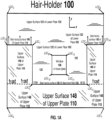
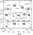
- FIGS. 1A-1B illustrates a top view of the hair-holder 100 , according to one example.
- Some embodiments relate to a system for optically acquiring data from hair, the system comprising: a hair-holder 100 including: upper 110 and lower 102 plate assemblies respectively having downward-facing 154 and upward-facing 122 opposing surfaces defining a gap 158 therebetween, the lower plate assembly 102 having a window-void 108 therein, the upper plate 110 assembly further comprising a sideward-facing sample-thickness-regulating surface 106 above the gap 158; and an alignment-wall 120 mechanically coupled to both plate assemblies and having a side-facing alignment surface 128 (i.e.
- the alignment surface 128 being straight along a longitudinal direction parallel to both 154, 122 of the opposing surfaces, the hair-holder being configured so that: when an externally-tensioned sample of hair is loaded onto the hair-holder by laterally moving the sample towards the alignment surface 128, a presence of the sideward-facing sample-thickness-regulating surface 106 regulates an amount of hair permitted to enter the gap 158, thereby regulating a thickness of hair above the window-void 108 to at least 0.5 mm and at most 2 mm; and after the loading and after release of the external tension, static friction applied by the side-facing alignment surface 128 upon shafts of the hair sample maintain alignment of hair above the window-void 108.
- the hair-holder 100 comprises (i) upper plate 110 and lower 102 plates (e.g. parallel to each other) defining a gap 158 therebetween and (ii) an alignment wall 120 in gap 158 or facing into the gap 158 - a side-facing surface 128 of alignment wall 120 is visible in FIGS. 1A-1B and 2A-2B .
- the function of alignment wall 120 is to maintain alignment of hair shafts within gap 158 - e.g. by static friction applied by alignment wall 120.
- alignment wall 120 may be straight along the x direction.
- the side-facing surface 128 is curved in a 'gap direction along the gap (i.e. the z direction) but is straight in a longitudinal direction (i.e. in the x direction)
- upper 110 and lower 102 plates are rigidly attached to each other to maintain a size of gap 158 characterized by a ⁇ gap distance' to a fixed value.
- the term ⁇ fixed value' refers to being held fixed in time - however, the gap distance may fluctuate as a function of x or y .
- the size of gap 158 i.e. distance between opposing surfaces 154 and 122)
- the gap distance may be fixed in multiple locations between the upper 110 and 102 plates - e.g. at a first and second locations on opposite sides (i.e. in the x direction of window 108.
- the gap distance may, in different embodiments, be at least 300 microns or at least 400 microns or at least 500 microns and/or at most 1 cm or at most 5 mm or at most 2 mm or at most 1.5 mm or at most 1 mm.
- upper 110 and lower 102 plates When upper 110 and lower 102 plates are 'rigidly' attached to each other, they may be directly or indirectly attached to each other - in some embodiments, upper 110 and lower 102 plates are rigidly attached to each via alignment wall 120 , though this is not a requirement.
- FIGS. 1A-1B Illustrated in FIGS. 1A-1B are the 14 locations LOC 1 - LOC 14 in the x-y plane, where "LOC" is an abbreviation for 'location.' A line segment between location LOC i and location LOC j (where i and j are positive integers) is denoted by Loc i Loc j .
- lower plate 102 is larger than upper plate 110; and (ii) the lower plate 102 is rectangular in shape - the borders of lower plate 102 are defined by the following four line-segments in the x-y plane (in counter-clockwise order): (i) Loc 5 Loc 6 , (ii) Loc 6 Loc 7 , (iii) Loc 7 Loc 8 and (iv) Loc 8 Loc 9 .
- upper plate 110 is present - thus, from a top view, upper surface 148 of upper plate 110 is visible and lower plate 104 (and an upper surface 122) thereof is occluded at these locations.
- lower plate 104 and an upper surface 122 thereof is occluded at these locations.
- upper plate 110 is absent - as such, in these locations from a top view upper surface 122 of lower plate 104 is visible.
- a window 108 within lower plate as well -e.g. characterized by a void in lower plate 102.
- Upper plate 110 has upper 148 and lower 154 surfaces facing in opposite directions. Because FIGS. 1A-1B illustrates a top view, only upper surface 148 is visible in FIGS. 1A-1B - lower surface 154 of upper plate 110 is not visible. In addition, as discussed above, upper surface 122 of lower plate 102 is visible in FIGS. 1A-1B and 2A-2E .
- the following surfaces 'face towards' gap 158 (i) upward-facing lower surface 154 of upper plate 110; (ii) downward-facing upper surface 122 of lower plate 102, and (iii) side-facing surface 128 of alignment-wall 120.
- the terms 'upward,' 'downward,' 'upper,' 'lower,' 'above,' 'below,' 'sideward' and 'sideways' are reference terms and are not intended as limiting - they refer to the situation where the hair-holder 100 is a whole is in the particular orientation where the lower plate 102 is in a horizontal orientation and below upper plate 110. It is appreciated that hair-holder 100 is not required to be used in this orientation.
- the hair-holder is used when a sample of hair is aligned in a given direction along an alignment-wall, and a side-facing alignment surface thereof maintains alignment .
- This direction is referred to as the 'longitudinal direction' and it is parallel to both upper surface 122 of lower plate 104 and to lower surface 154 of upper plate 110.
- the 'lateral direction' is (i) also parallel to both upper surface 122 of lower plate 104 and to lower surface 154 of upper plate 110; and (ii) is perpendicular to the 'longitudinal direction.'
- the hair-holder is loaded by movement of hair (e.g. under external tension to maintain shafts aligned with each other) in the 'lateral' direction.
- hair-holder 100 comprises an open sleeve having three walls (e.g. at right-angles to each other) - upper plate 110, alignment wall 120 and lower plate 102. Furthermore, at these positions lower plate 102 extends from alignment wall 120 to a greater extent than upper plate 110. Furthermore, illustrated in FIGS. 2A and 2E as well as 1A-1B is side-facing surface 106 of upper plate 110.
- the hair-holder 100 comprises two walls - e.g. at right angles.
- the hair-holder 100 comprises two walls - e.g. at right angles.
- upper-plate 110 is absent.
- FIGS. 3A -3E correspond to FIGS. 2A-2E - however, in the example of FIGS. 3A -3E it is shown that the hair-holder is 'flat' - i.e a characteristic length (i.e. along the x direction) and a characteristic width (i.e. along the y direction) is significantly greater (i.e. at least 3 times or at least 5 times or at least 7 times or at least 10 times) a characteristics thickness (i.e. along the z direction of the gap 158).
- FIGS. 4A -4E illustrate the loading of hair 200 into the hair-holder of FIGS. 1-3 - however, in the example of FIGS. 4A -4E of hair 200 (i.e. externally tensioned hair) (e.g. shafts of the hair sample are maintained in alignment with each other due to the external tension applied to the hair shafts)
- the side-facing surface 106 prevents this portion from entering into the gap 158 between the upper 110 and lower 120 plate.
- the presence of the upper plate 110 and side-facing surface 106 thereof regulates a 'gap distance' of gap 158 - e.g. to sizes/thicknesses described above.
- FIG. 5A is a top view of the hair-holder 100 after the hair is loaded but when the hair is under external tension.
- FIG. 5B is a top view of the hair-holder 100 after the hair is loaded but in the absence of external tension.
- FIGS. 6A-6B which respectively illustrate the ⁇ reflection configuration' and the 'transmission configuration' for the hair-holder deice of FIGS. 1-5 .
- the hair is illuminated by light source 102 (e.g. source of incoherent light) and reflected light (i.e. reflected by the illuminated hair 200) is received into spectrometer 300A or colorimeter 300B.
- light source 102 e.g. source of incoherent light
- reflected light i.e. reflected by the illuminated hair 200
- the hair is illuminated by light source 102 (e.g. source of incoherent light) and transmitted light (i.e. transmitted by the illuminated hair 200) is received into spectrometer 300A or colorimeter 300B.
- light source 102 e.g. source of incoherent light
- transmitted light i.e. transmitted by the illuminated hair 200
- FIG. 7A illustrates an alternative hair-holder device where the 'range' of upper plate 110 is greater than for the hair-holder device of FIGS. 1-5 .
- FIG. 7B is a side-view of the hair-holder device of FIG. 7A when used in a reflection configuration.
- FIG. 8 is a side-view of a hair-holder device where the side-facing surface 128 is curved in a ⁇ gap direction along the gap (i.e. the z direction) but is straight in a longitudinal direction (i.e. in the x direction)
- FIG. 9A is a flow chart of a method of subjecting hair to a spectral and/or colorimeter measurement using a hair-holder S101.
- step S101 the hair-holder 100 is provided.
- step S105 a sample of hair 200 is loaded onto the hair-holder S101.
- step S109 the hair is subjected to a spectral and/or colorimeteric measurement - e.g. using (i) illumination source 102 and/or (ii) spectrometer 300A or colorimeter 300B.
- FIG. 9B is like FIG. 9A but adds the optional step of predicting S113 result of a hair-coloring treatment and/or computing a hair-coloring treatment for the hair sample.
- ingredients for a hair-coloring compositions are dispensed (e.g. by an automatic mechanized dispenser in response and in accordance with the spectra or colorimetric data of the hair 200 is measured in step S109.
- Hair-holder 100 comprises: i. upper 110 and lower 102 plate assemblies respectively having downward-facing 154 and upward-facing 122 opposing surfaces defining a fixed gap 158 therebetween, a height of the fixed-gap 158 ranging between at least 200 microns (e.g. at most 300 microns or at most 400 microns or at most 500 microns) and at most 1 cm (e.g. at most 5 mm or at most 3 mm or at most 2 mm or at most 1.5 mm or at most 1 mm), the upper plate 110 assembly further comprising a sideward-facing sample-thickness-regulating surface 106 above the fixed-gap.
- the upper plate 110 assembly further comprising a sideward-facing sample-thickness-regulating surface 106 above the fixed-gap.
- Hair-holder 100 further comprises: ii. an alignment-wall 120 directly or indirectly rigidly attached to both 110, 102 plate assemblies, the alignment-wall 120 having a side-facing alignment surface 128 within gap 158 or sideways-facing into the gap 158, the alignment surface 128 being straight along a longitudinal direction parallel to both 154, 122 of the opposing surfaces.
- hair-holder 100 further comprises: a window-void 108 coplanar and/or within the upward-facing 122 surface.
- a cross-section of the hair-holder 100 is that of a 3-sided sleeve facing away from the alignment wall 120 such that the lower support surface 122 extends further away from the alignment wall 100 than the upper support surface.
- the first and second locations may be disposed at opposite longitudinal sides of the window-void 108.
- hair-holder device 100 of any the figures is 'flat' - i.e. a ratio between (i) a distance between a centroid of window-void 108 and alignment-wall 120 (or surface 128 thereof) and (ii) a thickness of gap 158 (or a representative thickness of the hair-sample of over window-void 108) is at least 3 or at least 5 or at least 10.
- step S105 the sample of hair 200 (e.g. under externally-tension - i.e. sufficient external tension to maintain shafts of the hair-sampled aligned with each other to design a longitudinal and/or alignment direction - e.g. aligned in the x-direction) is loaded onto hair holder 100.
- the loading may be formed by laterally (i.e. in the y-direction - i.e. in a direction perpendicular to alignment surface 128) moving shafts of the sample of hair 200 towards the alignment surface 128.
- This thickness may be regulated to at least 200 microns (e.g. at most 300 microns or at most 400 microns or at most 500 microns) and/or at most 1 cm (e.g. at most 5 mm or at most 3 mm or at most 2 mm or at most 1.5 mm or at most 1 mm).
- step S105 the sample of hair 200 is subjected to a spectral and/or colorimeteric measurement by illuminating the hair via the window-void.
- the spectral or colorimeteric data is analyzed in order to (i) predict the outcome of a hypothetical hair-coloring treatment as applied to the hair and/or (ii) calculate a customized hair-coloring treatment for the hair.
- FIG. 10 is a block diagram of a system for (i) optically measuring one or properties (e.g. spectra or colorimetric data) of hair and, (ii) in accordance with the optically-measured properties, dispensing material from containers to provide a customized hair-coloring composition.
- a user desires to color his/her hair to a target shade.
- An optical measurement of the user's "initial hair” is performed, and a hair-coloring composition, customized according to the initial state of the user's hair as well as the hair-coloring target is prepared.
- hair reader 3110 e.g. comprising hair-holder 100 and a colorimeter and/or spectrometer
- system controller 3120 includes dispensing decision engine 3140 which includes recipe-search engine 3150, prediction engine 3160 and recipe-scoring engine 3170.
- Hair reader 3110 optically acquires optical data from hair - for example by illuminating the hair and detecting light reflected by and/or transmitted by and/or deflected by the hair.
- System controller 3120 receives both the optical data and hair target data (e.g. describing a target shade desired the user). In accordance with the received data, the system controller 3120 computes (e.g. dispensing decision engine 3140) using a customized recipe for the hair-coloring composition - e.g. including respective quantities of a plurality of different materials stored in dispenser 3110.
- the dispenser proceeds to dispense the materials for the hair-coloring composition. These materials may be automatically or manually mixed to form a customized hair-coloring composition, which is applied to the user's hair.
- surface 106 is not required to be straight .
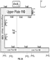
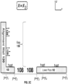
- Figs. 12A-12C show one non-limiting method of assembling the hair-holder by rotation of one plate assembly relative to the other plate assembly.
- Some embodiments of the present invention relate to methods and apparatus that were disclosed in PCT/IB2012/051351 which (i) was filed on March 21, 2012 ; and (ii) was published as WO/2012/127429 .
- Some embodiments of the present invention relate to methods and apparatus that were disclosed in PCT/IL2014/050850 which (i) was filed on September 28, 2014 ; and (ii) was published as WO/2015/044944 .
- Some embodiments of the present invention relate to methods and apparatus that were disclosed in PCT/IB2015/000724 which (i) was filed on March 25, 2015 ; and (ii) was published as WO/2015/166340 .
- Some embodiments of the present invention relate to methods and apparatus that were disclosed in PCT/IB2015/053065 which (i) was filed on April 27, 2015 ; and (ii) was published as WO/2015/166403 .
Landscapes
- Health & Medical Sciences (AREA)
- Life Sciences & Earth Sciences (AREA)
- Physics & Mathematics (AREA)
- Engineering & Computer Science (AREA)
- Chemical & Material Sciences (AREA)
- Biomedical Technology (AREA)
- Immunology (AREA)
- Analytical Chemistry (AREA)
- Pathology (AREA)
- Biochemistry (AREA)
- General Health & Medical Sciences (AREA)
- General Physics & Mathematics (AREA)
- Food Science & Technology (AREA)
- Medicinal Chemistry (AREA)
- Hematology (AREA)
- Biophysics (AREA)
- Urology & Nephrology (AREA)
- Optics & Photonics (AREA)
- Molecular Biology (AREA)
- Spectroscopy & Molecular Physics (AREA)
- Investigating Or Analysing Materials By Optical Means (AREA)
- Investigating Or Analysing Biological Materials (AREA)
- Measurement Of The Respiration, Hearing Ability, Form, And Blood Characteristics Of Living Organisms (AREA)
Description
- The present application is related to and claims the benefit of
U.S. Application No. 15/399,796, filed January 6, 2017 - The following issued patents and patent publications provide potentially relevant background material.
US 4643313 ,US 5205837 ,US 5660342 ,US 5754283 ,US 5851181 ,US 5990058 ,US 6096359 ,US 6170980 ,US 6248749 ,US 6362885 ,US 6529446 ,US 6547833 ,US 6613311 ,US 6707929 ,US 6764523 ,US 6790240 ,US 6818022 ,US 6984377 ,US 7110117 ,US 7204856 ,US 7304739 ,US 7458992 ,US 7463356 ,US 7508508 ,US 7523018 ,US 7708021 ,US 20010002025 ,US 20020010556 ,US 20020157191 ,US 20020194684 ,US 20030028978 ,US 20040000015 ,US 20040013616 ,US 20050015895 ,US 20050019398 ,US 20050039271 ,US 20050165705 ,US 20050177032 ,US 20050244343 ,US 20060149151 ,US 20060195300 ,US 20070159290 ,US 20070265867 ,US 20080013077 ,US 20080068604 ,US 20080256724 ,US 20090119852 ,US 20110038818 ,DE 10260880 ,DE 2006008149 ,DE 3609962 ,DE 4205112 ,EP 0590538 ,EP 1817976 ,EP 2081668 ,EP 2193781 ,FR 2402446 FR 2532174 FR 2901131 JP 2000116622 JP 2004198398 JP 2004212088 JP 2007212140 JP 2008285429 KR100802645 KR20040076861 WO 0145647 WO 02083282 WO 03012728 WO 03074015 WO 04101689 WO 11003554 WO 2004058202 ,WO 2004082650 ,WO 2004101689 ,WO 2008046518 ,WO 2009121643 ,WO 2009152033 ,WO 2010004565 ,WO 2010060601 ,WO 2010100231 ,WO 2012032671 ,WO/2015/166340 ,WO/2015/044944 andWO/2015/166403 . - 2004/198398 discloses a system for optically acquiring data from hair, the system comprising a light source, an optical measuring instrument and a hair-holder including upper and lower plate assemblies, whereby the lower plate assembly has a window-void, the lower plate assembly extends beyond the upper plate assembly and a gap for receiving hair is provided between the upper and lower plate assemblies.
- Embodiments of the invention relate to a system comprising a hair-holder device comprising upper and lower plate assemblies and adapted for use with an optical measuring instrument (e.g. spectrometer or camera). After a hair-sample is loaded into the hair-holder device, the hair-shafts of the sample are illuminated via a window-void of the lower-plate assembly. Light reflected from and/or transmitted by and/or deflected by the illuminated hair is collected by the optical measuring instrument.
- In different embodiments, the hair-holder device is designed (i) to minimize the effort required by a user (e.g. hair-dresser) who wishes to ensure that a very specific thickness of hair (i.e. between 0.5 mm and 2 mm) is disposed over a window-void of the lower-plate assembly; and (ii) to maintain alignment of hair-shafts that are disposed over the window-void, without requiring external tensioning for this purpose. In some embodiments, static friction applied by a side-facing alignment surface (discussed below) serves this purpose, and obviates the need for the user to maintain the sample of hair under external tension during imaging and/or measurement of spectrum(a).
- Data optically acquired by the optical measuring instrument may be used to predict a result of a hypothetical hair-treatment protocol and/or to compute a hair-treatment predicted to transform the hair to a target color-state.
- Systems including the hair-holder device and methods of using the hair-holder device are set out in the appended set of claims.
- A system for optically acquiring data from hair is set out in the appended set of claims.
- In some embodiments, the light-source is selected from the group consisting of an LED, a halogen source and a high intensity discharge source.
- In some embodiments, the light-source emits light at a wavelength of at least 750 nm.
- In some embodiments, further comprising a spectrometer for measuring at least one spectrum of the aligned shafts upon receiving, via the window-void, light reflected by or transmitted by or deflected by the aligned shafts.
- In some embodiments, further comprising a digital camera for digitally acquiring a digital image of the aligned shafts upon receiving, via the window-void, from light reflected by or transmitted by or deflected by the aligned shafts.
- In some embodiments, further comprising a hair-coloring prediction engine for predicting from the digital image and/or from the spectrum(a), a result of a hypothetical hair-coloring treatment upon hair of the sample.
- In some embodiments, further comprising an automatic dispenser having a plurality of compartments, each compartment storing a different respective hair-coloring material, the dispenser configured to produce a mixture of ingredients for a customized hair-coloring treatment by automatically dispensing material from each of the compartments at relative quantities computed in accordance with the digital image or the spectrum(a) or the prediction of the hair-coloring treatment.
- A method for optically acquiring data from hair is set out in the appended set of claims.
- In some embodiments, further comprising illuminate the aligned shafts via the window-void.
- In some embodiments, the light-source is selected from the group consisting of an LED, a halogen source and a high intensity discharge source.
- In some embodiments, the light-source emits light at a wavelength of at least 750 nm.
- In some embodiments, further comprising receiving, via the window-void and by a spectrometer, light that is reflected by or transmitted by or deflected by the aligned shafts, so as to measure at least one spectrum of the aligned shafts.
- In some embodiments, further comprising receiving, via the window-void and by a digital camera, light that is reflected by or transmitted by or deflected by the aligned shafts, so as to digitally acquire an image of the aligned shafts.
- In some embodiments, further comprising electronically operating a hair-coloring prediction engine to predict from the digital image and/or from the spectrum(a), a result of a hypothetical hair-coloring treatment upon hair of the sample.
- In some embodiments, further comprising: providing an automatic dispenser having a plurality of compartments, each compartment storing a different respective hair-coloring material; and operating the automatic dispenser to produce a mixture of ingredients for a customized hair-coloring treatment by automatically and electronically dispensing material from each of the compartments at relative quantities computed in accordance with the digital image or the spectrum(a) or the prediction of the hair-coloring treatment.
- In some embodiments, the upper and lower plate assemblies are engaged to each other by rotating one relative to the other.
- In some embodiments, the upper and lower plate assemblies are engaged to each other by rotating one relative to the other so that before rotation an angle between a the downward-facing surface of the upper plate and the upward-facing surface of the lower plate as opposing is at least 20 degrees, and after rotation they are parallel to each other.
- In some embodiments, the externally tensioned sample of hair is root-region-external hair that is external to the hair-root-region.
- In some embodiments, further comprising illuminating the aligned hair shafts of the root-region-external hair of the hair-holder , and receiving light reflected by or deflected by or transmitted by the aligned hair shafts into a spectrometer or digital camera to measure a spectrum or acquire a digital image.
- In some embodiments, further comprising: disassembling the hair-holder by disengaging the upper and lower plate assemblies from each other; illuminating hair roots of the hair of the sample via the window void of the lower plate, and receiving light reflected by or deflected by or transmitted by the hair roots into a spectrometer or digital camera to measure a spectrum or acquire a digital image.
- In some embodiments, further comprising: before the assembling of the hair-holder , illuminating hair roots of the hair of the sample via the window void of the lower plate, and receiving light reflected by or deflected by or transmitted by the hair roots into a spectrometer or digital camera to measure a spectrum or acquire a digital image.
- In some embodiments, the fixed value of the thickness of hair above the window-void is at least 400 microns.
- In some embodiments, the fixed value of the thickness of hair above the window-void is at most 5 mm, or at most 3 mm or at most 2 mm.
- In some embodiments, a reflection spectrum is generated from light reflected by the illuminated hair.
-
-
Figs. 1A-1B ,2A-2E, 3A-3C, 4A-4C, 5A-5B, 6A-6B, 7A-7B, 8 and11 show various views of a presently-disclosed hair-holder. -
Figs. 9A-9B illustrate a method of using the hair-holder. -
Fig. 10 is a flow-chart off a system including the hair-holder. -
Fig. 12A-12C illustrate assembly of the hair-holder by rotation. - The claims below will be better understood by referring to the present detailed description of example embodiments with reference to the figures. The description, embodiments and figures are not to be taken as limiting the scope of the claims. It should be understood that not every feature of the presently disclosed methods and apparatuses is necessary in every implementation. It should also be understood that throughout this disclosure, where a process or method is shown or described, the steps of the method may be performed in any order or simultaneously, unless it is clear from the context that one step depends on another being performed first. As used throughout this application, the word "may" is used in a permissive sense (i.e., meaning "having the potential to'), rather than the mandatory sense (i.e. meaning "must").
- Embodiments of the invention relate to a system comprising a hair-holder device comprising upper and lower plate assemblies and adapted for use with an optical measuring instrument (e.g. spectrometer or camera). In some embodiments, after a hair-sample loaded into the hair-holder device, the hair-shafts of the sample are illuminated via a window-void of the lower-plate assembly and light reflected from and/or transmitted by and/or deflected by the illuminated hair is collected by the optical measuring instrument.
- In different embodiments, the hair-holder device is designed (i) to minimize the effort required by a user (e.g. hair-dresser) who wishes to ensure that a very specific thickness of hair (i.e. between 0.5 mm and 2 mm) is disposed over a window-void of the lower-plate assembly; and (ii) to maintain alignment of hair-shafts that are disposed over the window-void, without requiring external tensioning for this purpose.
- Experiments indicate that when acquiring spectral or colorimetric data of a sample of hair, a certain thickness may be required in order to obtain results that are not dependent upon the sample thickness - the exact thickness required may depend upon the color or other property(ies) of the hair. For example, in some experiments, a minimum sample thickness of about 400 µ is required to achieve a situation where spectral measurements are independent of sample thickness.
- Furthermore, it is desired measure aligned hair-shafts. Not wishing to be bound by theory, aligned hair shafts are preferred since, due to hair anisotropy, the hair color appearance may depend upon the direction of the hair shafts relative to an illumination direction of incident light and/or a reflection direction (or transmission direction) of reflected or transmitted light.
- Embodiments of the present invention relate to hair-reading system and method for acquiring spectral or colorimetric data from a sample of hair. The sample is loaded into a hair-
holder 100 comprising a window-void 108, and an alignment wall for maintaining alignment of shafts of the hair-sample above the window-void. In some embodiments, the geometry of the hair-holder regulates a thickness of the hair-sample that is permitted to locate above the window-void. In different embodiments, ther thickness may be at least 300 µ or at least 400 µ or at least 500 µ or at least 600 µ of hair and/or at most 1 cm at 5 mm or at most 3 mm or at most 2 mm or at most 1.5 mm or at most 1 mm. - As noted above, the hair-
holder 110 comprises analignment wall 120 for maintaining alignment of shafts of the hair-sample above the window-void 108. In some embodiments, as a result of the mechanical properties of the hair-holder, it is not necessary for a user to maintain the hair sample under external tension for the hair-shafts to stay aligned over the window-void 108 - instead, static friction applied by a surface(s) of the hair-holder and the hair-shafts may suffice to maintain hair shaft alignment. - After loading, the sample of hair is illuminated via the window-
void 108. Spectral or colorimeteric data is acquired from light that is scattered and/or deflected and/or reflected from the illuminated hair. In some embodiments, the spectral or colorimeteric data is analyzed in order to (i) predict the outcome of a hypothetical hair-coloring treatment as applied to the hair and/or (ii) calculate a customized hair-coloring treatment for the hair. - A `window void' in a plate assembly is an opening in the plate assembly via which light passes. In contrast to a 'window' which is a transparent object via which light may pass, the `window void' is empty space. A window-
void 108 may be preferred to a transparent window since the latter might be susceptible to accumulation of dirt on the transparent surface. - Some embodiments of the present invention relate to hair-reading system comprising: (A) a spectrometer or
colorimeter 200 for subjecting a hair sample to a spectral or colorimeter measurement and (B) the aforementioned hair-holder 100. -
FIGS. 1A-1B illustrates a top view of the hair-holder 100, according to one example.FIGS. 2A-2E illustrates cross-section/side view of the hair-holding devices respectively at positions x=x1, x=x2, x=x3, x=x4, and x=x5. - Some embodiments relate to a system for optically acquiring data from hair, the system comprising: a hair-holder 100 including: upper 110 and lower 102 plate assemblies respectively having downward-facing 154 and upward-facing 122 opposing surfaces defining a gap 158 therebetween, the lower plate assembly 102 having a window-void 108 therein, the upper plate 110 assembly further comprising a sideward-facing sample-thickness-regulating surface 106 above the gap 158; and an alignment-wall 120 mechanically coupled to both plate assemblies and having a side-facing alignment surface 128 (i.e. that is within gap 158 or sideward-facing into the gap 158), the alignment surface 128 being straight along a longitudinal direction parallel to both 154, 122 of the opposing surfaces, the hair-holder being configured so that: when an externally-tensioned sample of hair is loaded onto the hair-holder by laterally moving the sample towards the alignment surface 128, a presence of the sideward-facing sample-thickness-regulating surface 106 regulates an amount of hair permitted to enter the gap 158, thereby regulating a thickness of hair above the window-void 108 to at least 0.5 mm and at most 2 mm; and after the loading and after release of the external tension, static friction applied by the side-facing alignment surface 128 upon shafts of the hair sample maintain alignment of hair above the window-void 108.
- In the examples of
FIGS. 1A-1B and2A-2E the hair-holder 100 comprises (i)upper plate 110 and lower 102 plates (e.g. parallel to each other) defining agap 158 therebetween and (ii) analignment wall 120 ingap 158 or facing into the gap 158 - a side-facingsurface 128 ofalignment wall 120 is visible inFIGS. 1A-1B and2A-2B . As will be discussed below, the function ofalignment wall 120 is to maintain alignment of hair shafts within gap 158 - e.g. by static friction applied byalignment wall 120. Towards this end and as illustrated inFIGS. 1A-1B ,alignment wall 120 may be straight along the x direction. In the example ofFIG. 8 the side-facingsurface 128 is curved in a 'gap direction along the gap (i.e. the z direction) but is straight in a longitudinal direction (i.e. in the x direction) - In some embodiments, upper 110 and lower 102 plates are rigidly attached to each other to maintain a size of
gap 158 characterized by a `gap distance' to a fixed value. The term `fixed value' refers to being held fixed in time - however, the gap distance may fluctuate as a function of x or y. The size of gap 158 (i.e. distance between opposingsurfaces 154 and 122)) may be fixed in multiple locations between the upper 110 and 102 plates - e.g. at a first and second locations on opposite sides (i.e. in the x direction ofwindow 108. The gap distance may, in different embodiments, be at least 300 microns or at least 400 microns or at least 500 microns and/or at most 1 cm or at most 5 mm or at most 2 mm or at most 1.5 mm or at most 1 mm. - When upper 110 and lower 102 plates are 'rigidly' attached to each other, they may be directly or indirectly attached to each other - in some embodiments, upper 110 and lower 102 plates are rigidly attached to each via
alignment wall 120, though this is not a requirement. - Illustrated in
FIGS. 1A-1B are the 14 locations LOC1 - LOC14 in the x-y plane, where "LOC" is an abbreviation for 'location.' A line segment between location LOCi and location LOCj (where i and j are positive integers) is denoted byLociLocj . - As illustrated in non-limiting example of the figures, (i)
lower plate 102 is larger thanupper plate 110; and (ii) thelower plate 102 is rectangular in shape - the borders oflower plate 102 are defined by the following four line-segments in the x-y plane (in counter-clockwise order): (i)Loc 5 Loc 6 , (ii)Loc 6 Loc 7 , (iii)Loc 7 Loc 8 and (iv)Loc 8 Loc 9 . In contrast, because the outer borders ofupper plate 110 have a more complex shape, eight line-segments are required to define the shape of the outer borders of upper plate 110 (in counter-clockwise order): (i)Loc 13 Loc 6 (ii)Loc 6 Loc 7 , (iii)Loc 7 Loc 14 ; (iv)Loc 14 Loc 4 ; (v)Loc 4 Loc 3 ; (vi)Loc 3 Loc 2 ; (vii)Loc 2 Loc 1 and (viii)Loc 1 Loc 13 . - In the non-limiting example hair-holder illustrated in the figures, locations within the shape defined by the aforementioned eight line-segments,
upper plate 110 is present - thus, from a top view,upper surface 148 ofupper plate 110 is visible and lower plate 104 (and an upper surface 122) thereof is occluded at these locations. In contrast, in locations in the rectangular-shaped region of space defined by y4<y< y5 (alternatively, defined by the four locations LOC5, LOC13, LOC14, and LOC8 )upper plate 110 is absent - as such, in these locations from a top viewupper surface 122 of lower plate 104 is visible. Similarly, in locations in the rectangular-shaped region of space where the following two inequalities are simultaneously true (i) y1<y< y4 and (ii) xA <x< xB (alternatively, defined by the four locations LOC 51 LOC2, LOC3, and LOC4 )upper plate 110 is absent as well - as such, in these locations as well from a top viewupper surface 122 of lower plate 104 is visible. - In some embodiments, there is a
window 108 within lower plate as well -e.g. characterized by a void inlower plate 102. -
Upper plate 110 has upper 148 and lower 154 surfaces facing in opposite directions. BecauseFIGS. 1A-1B illustrates a top view, onlyupper surface 148 is visible inFIGS. 1A-1B -lower surface 154 ofupper plate 110 is not visible. In addition, as discussed above,upper surface 122 oflower plate 102 is visible inFIGS. 1A-1B and2A-2E . - As noted above,
FIGS. 2A-2E are side views of cross sections of the hair-holder at positions x=x1, x=x2, x=x3, x=x4, and x=x5. As shown inFIGS. 2A-2E , the following surfaces 'face towards' gap 158: (i) upward-facinglower surface 154 ofupper plate 110; (ii) downward-facingupper surface 122 oflower plate 102, and (iii) side-facingsurface 128 of alignment-wall 120. - The terms 'upward,' 'downward,' 'upper,' 'lower,' 'above,' 'below,' 'sideward' and 'sideways' are reference terms and are not intended as limiting - they refer to the situation where the hair-
holder 100 is a whole is in the particular orientation where thelower plate 102 is in a horizontal orientation and belowupper plate 110. It is appreciated that hair-holder 100 is not required to be used in this orientation. - As discussed below, the hair-holder is used when a sample of hair is aligned in a given direction along an alignment-wall, and a side-facing alignment surface thereof maintains alignment . This direction is referred to as the 'longitudinal direction' and it is parallel to both
upper surface 122 of lower plate 104 and tolower surface 154 ofupper plate 110. The 'lateral direction' is (i) also parallel to bothupper surface 122 of lower plate 104 and tolower surface 154 ofupper plate 110; and (ii) is perpendicular to the 'longitudinal direction.' As shown inFigs. 4A-4C , the hair-holder is loaded by movement of hair (e.g. under external tension to maintain shafts aligned with each other) in the 'lateral' direction. - Reference is made to
FIGS. 2A and2E which are identical and respectively refer to cross sections at positions x=x1 , and x=x5. At these x positions, hair-holder 100 comprises an open sleeve having three walls (e.g. at right-angles to each other) -upper plate 110,alignment wall 120 andlower plate 102. Furthermore, at these positionslower plate 102 extends fromalignment wall 120 to a greater extent thanupper plate 110. Furthermore, illustrated inFIGS. 2A and2E as well as 1A-1B is side-facingsurface 106 ofupper plate 110. - Thus, as shown in
FIGS. 2B and2D , at positions x=x2, and x=x4 the hair-holder 100 comprises two walls - e.g. at right angles. At positions x=x2 , and x=x4 upper-plate 110 is absent. The cross-section ofFIG. 2C at position x=x3 illustrateswindow 108 which is a void withinlower plate 102. -
FIGS. 3A -3E correspond toFIGS. 2A-2E - however, in the example ofFIGS. 3A -3E it is shown that the hair-holder is 'flat' - i.e a characteristic length (i.e. along the x direction) and a characteristic width (i.e. along the y direction) is significantly greater (i.e. at least 3 times or at least 5 times or at least 7 times or at least 10 times) a characteristics thickness (i.e. along the z direction of the gap 158). -
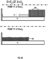
FIGS. 4A -4E illustrate the loading ofhair 200 into the hair-holder ofFIGS. 1-3 - however, in the example ofFIGS. 4A -4E of hair 200 (i.e. externally tensioned hair) (e.g. shafts of the hair sample are maintained in alignment with each other due to the external tension applied to the hair shafts)FIG.4A corresponds to x=x1 (seeFIGS. 2A and3A ) and x=x5 (seeFIGS. 2E and 3E) ; F1G.4B corresponds to x=x2 (seeFIGS. 2B and3B ) and x=x4 (seeFIGS. 2D and 3D) ;FIG.4C corresponds to x=x3 (seeFIGS. 2C and3C ). - For each of
FIGS. 4A -4E, the hair is moved while under external tension in the -y direction --- `Frame A' illustrates the hair as it is being moved and some of the hair first reachessurface 106 at an earlier point in time t=t1 . When a portion of the hair sample reaches and comes into contact with side-facingsurface 106 ofupper plate 110, the side-facingsurface 106 prevents this portion from entering into thegap 158 between the upper 110 and lower 120 plate. In this manner, the presence of theupper plate 110 and side-facingsurface 106 thereof regulates a 'gap distance' of gap 158 - e.g. to sizes/thicknesses described above. - Not wishing to be bound by theory, it is now disclosed that (I) if this 'gap distance' is too small, then not enough hair will be present above
window 108 to obtain an accurate and/or meaningful (e.g. for the purpose of predicting hair coloring) spectral and/or colorimetric measurement of hair of the sample and (ii) if this 'gap distance' is too much then 'too large of a quantity' of hair will be required to fill the hair-holder causing possible inconvenience to the hair-stylist and/of the 'subject' whose hair is being subjected to measurements. - In some embodiments, upon reaching the situation of 'frame B' static friction maintains the hair sample in an 'aligned configuration' even in the absence of external tension applied to the hair sample. Examples of this are illustrated in
FIGS. 5A and5B - inFIG. 5A external tension is still applied corresponding to FRAME "B (time = t2) forFIGS. 4A-4C while at a later time (FRAME C at time=t3) even in the absence of the external tension, the hair remains (e.g. due to static friction) in the aligned configuration within the hair-holder (e.g. at locations above window 108). - Thus,
FIG. 5A is a top view of the hair-holder 100 after the hair is loaded but when the hair is under external tension.FIG. 5B is a top view of the hair-holder 100 after the hair is loaded but in the absence of external tension. - After loading, (i) the sample of
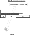
hair 200 is illuminated via the window-void 108 and (ii) spectral or colorimeteric data is acquired from light that is scattered and/or deflected and/or reflected from the illuminated hair. This is shown inFIGS. 6A-6B which respectively illustrate the `reflection configuration' and the 'transmission configuration' for the hair-holder deice ofFIGS. 1-5 . - In the reflection configuration of
FIG. 6A , the hair is illuminated by light source 102 (e.g. source of incoherent light) and reflected light (i.e. reflected by the illuminated hair 200) is received intospectrometer 300A orcolorimeter 300B. - In the transmission configuration of
FIG. 6B , the hair is illuminated by light source 102 (e.g. source of incoherent light) and transmitted light (i.e. transmitted by the illuminated hair 200) is received intospectrometer 300A orcolorimeter 300B. -
FIG. 7A illustrates an alternative hair-holder device where the 'range' ofupper plate 110 is greater than for the hair-holder device ofFIGS. 1-5 .FIG. 7B is a side-view of the hair-holder device ofFIG. 7A when used in a reflection configuration. -
FIG. 8 is a side-view of a hair-holder device where the side-facingsurface 128 is curved in a `gap direction along the gap (i.e. the z direction) but is straight in a longitudinal direction (i.e. in the x direction) -
FIG. 9A is a flow chart of a method of subjecting hair to a spectral and/or colorimeter measurement using a hair-holder S101. In step S101, the hair-holder 100 is provided. In step S105, a sample ofhair 200 is loaded onto the hair-holder S101. In step S109, the hair is subjected to a spectral and/or colorimeteric measurement - e.g. using (i)illumination source 102 and/or (ii)spectrometer 300A orcolorimeter 300B. -
FIG. 9B is likeFIG. 9A but adds the optional step of predicting S113 result of a hair-coloring treatment and/or computing a hair-coloring treatment for the hair sample. Optionally, ingredients for a hair-coloring compositions are dispensed (e.g. by an automatic mechanized dispenser in response and in accordance with the spectra or colorimetric data of thehair 200 is measured in step S109. - Some of these steps will now be discussed, in accordance with example embodiments.
- Hair-
holder 100 comprises: i. upper 110 and lower 102 plate assemblies respectively having downward-facing 154 and upward-facing 122 opposing surfaces defining afixed gap 158 therebetween, a height of the fixed-gap 158 ranging between at least 200 microns (e.g. at most 300 microns or at most 400 microns or at most 500 microns) and at most 1 cm (e.g. at most 5 mm or at most 3 mm or at most 2 mm or at most 1.5 mm or at most 1 mm), theupper plate 110 assembly further comprising a sideward-facing sample-thickness-regulatingsurface 106 above the fixed-gap. - Hair-
holder 100 further comprises: ii. an alignment-wall 120 directly or indirectly rigidly attached to both 110, 102 plate assemblies, the alignment-wall 120 having a side-facingalignment surface 128 withingap 158 or sideways-facing into thegap 158, thealignment surface 128 being straight along a longitudinal direction parallel to both 154, 122 of the opposing surfaces. - In some embodiments, hair-
holder 100 further comprises: a window-void 108 coplanar and/or within the upward-facing 122 surface. - In some embodiments, at both first (e.g. when x=x1 - see
FIG. 2A ) and second (e.g. when x=x5 - seeFIG. 2E ) locations along the longitudinal direction (e.g. the alignment direction of hair of the hair sample) , a cross-section of the hair-holder 100 is that of a 3-sided sleeve facing away from thealignment wall 120 such that thelower support surface 122 extends further away from thealignment wall 100 than the upper support surface. For example, the first and second locations may be disposed at opposite longitudinal sides of the window-void 108. - In some embodiments, hair-
holder device 100 of any the figures is 'flat' - i.e. a ratio between (i) a distance between a centroid of window-void 108 and alignment-wall 120 (orsurface 128 thereof) and (ii) a thickness of gap 158 (or a representative thickness of the hair-sample of over window-void 108) is at least 3 or at least 5 or at least 10. - In step S105, the sample of hair 200 (e.g. under externally-tension - i.e. sufficient external tension to maintain shafts of the hair-sampled aligned with each other to design a longitudinal and/or alignment direction - e.g. aligned in the x-direction) is loaded onto
hair holder 100. The loading may be formed by laterally (i.e. in the y-direction - i.e. in a direction perpendicular to alignment surface 128) moving shafts of the sample ofhair 200 towards thealignment surface 128. - In different embodiments, this may be performed such that during loading, a presence of the sideward-facing sample-thickness-regulating
surface 106 on opposite longitudinal-sides of the window-void 108 (e.g. at x=x1 and x=x5) regulates an amount of hair permitted to enter the gap so as to regulate a thickness of hair above the window-void 108. This thickness may be regulated to at least 200 microns (e.g. at most 300 microns or at most 400 microns or at most 500 microns) and/or at most 1 cm (e.g. at most 5 mm or at most 3 mm or at most 2 mm or at most 1.5 mm or at most 1 mm). - In some embodiments, after loading and after release of the external tension (i.e. so the hair is no longer externally tensioned- e.g. so no tension is applied on the hair and the only relevant forces applied upon hair above the
window 108 are applied by hair holder 100), static friction applied by the side-facingalignment surface 128 upon shafts of the hair sample maintain alignment of hair above the window-void 108; - In step S105, the sample of
hair 200 is subjected to a spectral and/or colorimeteric measurement by illuminating the hair via the window-void. - As noted above, the spectral or colorimeteric data is analyzed in order to (i) predict the outcome of a hypothetical hair-coloring treatment as applied to the hair and/or (ii) calculate a customized hair-coloring treatment for the hair.
-
FIG. 10 is a block diagram of a system for (i) optically measuring one or properties (e.g. spectra or colorimetric data) of hair and, (ii) in accordance with the optically-measured properties, dispensing material from containers to provide a customized hair-coloring composition. For example, a user desires to color his/her hair to a target shade. An optical measurement of the user's "initial hair" is performed, and a hair-coloring composition, customized according to the initial state of the user's hair as well as the hair-coloring target is prepared. - Illustrated in
FIG. 10 are hair reader 3110 (e.g. comprising hair-holder 100 and a colorimeter and/or spectrometer),system controller 3120, anddispenser device 3130. In the non-limiting example ofFIG. 9 ,system controller 3120 includes dispensingdecision engine 3140 which includes recipe-search engine 3150,prediction engine 3160 and recipe-scoring engine 3170. -
Hair reader 3110 optically acquires optical data from hair - for example by illuminating the hair and detecting light reflected by and/or transmitted by and/or deflected by the hair. System controller 3120 (e.g. comprising a digital computer) receives both the optical data and hair target data (e.g. describing a target shade desired the user). In accordance with the received data, thesystem controller 3120 computes (e.g. dispensing decision engine 3140) using a customized recipe for the hair-coloring composition - e.g. including respective quantities of a plurality of different materials stored indispenser 3110. - The dispenser proceeds to dispense the materials for the hair-coloring composition. These materials may be automatically or manually mixed to form a customized hair-coloring composition, which is applied to the user's hair.
- As shown in
Fig. 11 ,surface 106 is not required to be straight . -
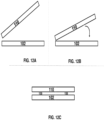
Figs. 12A-12C show one non-limiting method of assembling the hair-holder by rotation of one plate assembly relative to the other plate assembly. - Some embodiments of the present invention relate to methods and apparatus that were disclosed in
PCT/IB2012/051351 which (i) was filed on March 21, 2012 ; and (ii) was published asWO/2012/127429 . - Some embodiments of the present invention relate to methods and apparatus that were disclosed in
PCT/IL2014/050850 which (i) was filed on September 28, 2014 WO/2015/044944 . - Some embodiments of the present invention relate to methods and apparatus that were disclosed in
PCT/IB2015/000724 which (i) was filed on March 25, 2015 ; and (ii) was published asWO/2015/166340 . - Some embodiments of the present invention relate to methods and apparatus that were disclosed in
PCT/IB2015/053065 which (i) was filed on April 27, 2015 ; and (ii) was published asWO/2015/166403 . - Although the invention has been described in conjunction with specific embodiments thereof, it is evident that many alternatives, modifications and variations will be apparent to those skilled in the art. Accordingly, it is intended to embrace all such alternatives, modifications and variations that fall within the scope of the appended claims.
Claims (14)
- A system for optically acquiring data from hair, the system comprising:at least one light source (102);at least one optical measuring instrument (200); and
a hair-holder (100) including:upper and lower plate assemblies (110, 102) respectively having downward-facing and upward-facing opposing surfaces (154, 122) defining a gap (158) therebetween, the lower plate assembly having a window-void (108) therein, one side face (106) of the upper plate assembly defining a sideward-facing sample-thickness-regulating surface located above the gap, the lower plate assembly extending beyond the upper plate assembly in the direction orthogonal to the sideward-facing surface; andan alignment-wall (120) rigidly mechanically coupled to both plate assemblies along the lengths of the sides of the upper and lower plates which are opposite to the sideward-facing surface, the wall having a side-facing alignment surface (128) defining the and facing into the gap, the alignment surface being straight along a longitudinal direction which is orthogonal to both of the opposing surfaces, the hair-holder being configured so that:when a sample of hair, which is externally-tensioned in a direction parallel to the sideward-facing surface and orthogonal to the longitudinal direction is loaded into the hair-holder by laterally moving the sample towards the alignment surface, the presence of the sideward-facing sample-thickness-regulating surface together with the upper surface of the lower plate regulates an amount of hair permitted to enter the gap (158), thereby regulating the thickness of hair above the window-void in the longitudinal direction to at least 0.5 mm and at most 2 mm; and after the loading and after release of the external tension, static friction applied by the side-facing alignment surface upon shafts of the hair sample maintain alignment of hair above the window-void,wherein the upper plate assembly has a window-void therein, at least a portion of the window-void of the upper plate assembly being directly above the window-void of the lower plate assembly. - The system of claim 1 further comprising at least one light-source configured to illuminate the aligned shafts via the window-void.
- The system of claim 2 wherein the light-source is selected from the group consisting of an LED, a halogen source and a high intensity discharge source.
- The system of claim 2 wherein the light-source emits light at a wavelength of at least 750 nm.
- The system of claim 1 further comprising a spectrometer for measuring at least one spectrum of the aligned shafts upon receiving, via the window-void, light reflected by or transmitted by or deflected by the aligned shafts.
- The system of any previous claim further comprising a digital camera for digitally acquiring a digital image of the aligned shafts upon receiving, via the window-void, from light reflected by or transmitted by or deflected by the aligned shafts.
- The system of claim 5 further comprising a hair-coloring prediction engine for predicting from the digital image and/or from the spectrum (a), a result of a hypothetical hair-coloring treatment upon hair of the sample.
- The system of claim 5 further comprising an automatic dispenser having a plurality of compartments, each compartment storing a different respective hair-coloring material, the dispenser configured to produce a mixture of ingredients for a customized hair-coloring treatment by automatically dispensing material from each of the compartments at relative quantities computed in accordance with the digital image or the spectrum(a) or the prediction of the hair-coloring treatment.
- A method for optically acquiring data from hair, the method comprising:providing the system defined by claim 1 wherein the hair-holder includes :
upper and lower plate assemblies respectively having downward-facing and upward-facing opposing surfaces defining a fixed gap therebetween, the lower plate assembly having a window-void therein, one side of the upper plate assembly defining a sideward-facing sample-thickness-regulating surface located above the gap, the lower plate assembly extending beyond the upper plate assembly in the direction orthogonal to the sideward-facing surface; and an alignment-wall rigidly mechanically coupled to both plate assemblies along the lengths of the sides of the upper and lower plates which are opposite to the sideward-facing surface, the wall having a side-facing alignment surface defining the gap and facing into the gap, the alignment surface being straight along a longitudinal direction which is orthogonal to both of the opposing surfaces;receiving a sample of hair which is externally tensioned in a direction parallel to the sideward-facing surface and orthogonal to the longitudinal direction into the hair-holder such that the externally-tensioned sample of hair is laterally moved towards the alignment surface whereby the presence of the sideward-facing sample-thickness regulating surface together with the upper surface of the lower plate regulates an amount of hair permitted to enter the gap, thereby regulating the thickness of hair above the window-void in the longitudinal direction to a fixed value of at least 0.5 mm and at most 2 mm; and after the loading and after release of the external tension, the side-facing alignment surface applies static friction upon shafts of the hair sample so as to maintain alignment of hair above the window-void. - The method of claim 9 further comprising illuminate the aligned shafts via the window-void.
- The method of claim 10 wherein the light-source is selected from the group consisting of an LED, a halogen source and a high intensity discharge source.
- The method of claim 10 wherein the light-source emits light at a wavelength of at least 750 nm.
- The method of claim 9 further comprising receiving, via the window-void and by a spectrometer, light that is reflected by or transmitted by or deflected by the aligned shafts, so as to measure at least one spectrum of the aligned shafts.
- The method of claim 9 further comprising receiving, via the window-void and by a digital camera, light that is reflected by or transmitted by or deflected by the aligned shafts, so as to digitally acquire an image of the aligned shafts.
Applications Claiming Priority (2)
| Application Number | Priority Date | Filing Date | Title |
|---|---|---|---|
| US15/399,796 US10292482B2 (en) | 2017-01-06 | 2017-01-06 | Hair-holder, hair-reader comprising the same, and methods for optically acquiring data from hair |
| PCT/IB2018/000040 WO2018127784A1 (en) | 2017-01-06 | 2018-01-08 | Hair-holder, hair-reader comprising the same, and methods for optically acquiring data from hair |
Publications (3)
| Publication Number | Publication Date |
|---|---|
| EP3566043A1 EP3566043A1 (en) | 2019-11-13 |
| EP3566043B1 true EP3566043B1 (en) | 2023-06-21 |
| EP3566043C0 EP3566043C0 (en) | 2023-06-21 |
Family
ID=61526834
Family Applications (1)
| Application Number | Title | Priority Date | Filing Date |
|---|---|---|---|
| EP18708194.8A Active EP3566043B1 (en) | 2017-01-06 | 2018-01-08 | System and method for optically acquiring data from hair |
Country Status (5)
| Country | Link |
|---|---|
| US (1) | US10292482B2 (en) |
| EP (1) | EP3566043B1 (en) |
| CN (1) | CN110178017B (en) |
| ES (1) | ES2950386T3 (en) |
| WO (1) | WO2018127784A1 (en) |
Families Citing this family (7)
| Publication number | Priority date | Publication date | Assignee | Title |
|---|---|---|---|---|
| US10863816B2 (en) * | 2015-11-04 | 2020-12-15 | Coloright Ltd. | Method and system for customized hair-coloring |
| WO2020125923A1 (en) * | 2018-12-17 | 2020-06-25 | L'oreal | Support device for holding a hair sample for measurements |
| FR3094201B1 (en) * | 2019-03-26 | 2022-11-18 | Oreal | Method for determining parameters specific to the personalized coloring of hairs of a given individual |
| EP4087546A1 (en) | 2020-01-10 | 2022-11-16 | Lasercap Company - Transdermal Cap, Inc. | Method and device for evaluating hair growth treatments |
| FR3126782A1 (en) * | 2021-09-03 | 2023-03-10 | L'oreal | Sample holder intended to support a lock of hair, kit for analysis of lock of hair and associated method |
| JP7397136B1 (en) * | 2022-08-26 | 2023-12-12 | 大日精化工業株式会社 | Fiber holder and fiber color measurement method |
| FR3149383A1 (en) | 2023-06-02 | 2024-12-06 | L'oreal | Device for inspecting a portion of the human body comprising two types of light sources |
Citations (2)
| Publication number | Priority date | Publication date | Assignee | Title |
|---|---|---|---|---|
| JP2004198398A (en) * | 2002-10-23 | 2004-07-15 | Kose Corp | Instrument for measuring hair color |
| JP3641370B2 (en) * | 1998-10-12 | 2005-04-20 | 株式会社コーセー | Hair gloss measuring instrument |
Family Cites Families (76)
| Publication number | Priority date | Publication date | Assignee | Title |
|---|---|---|---|---|
| FR2402446A1 (en) | 1977-09-07 | 1979-04-06 | Oreal | Hair dyeing compsn. contg. specified cationic polymer - fatty acid, alkali, benzyl alcohol and oxidn. dye |
| DE3329916C2 (en) | 1982-08-30 | 1994-04-07 | Bristol Myers Squibb Co | Oxidation hair |
| US4643313A (en) | 1985-11-26 | 1987-02-17 | Robson Charles H | Apparatus for the controlled dispensing of tablets from multiple containers |
| DE3609962A1 (en) | 1985-12-14 | 1987-06-19 | Hartmut Panke | Hair dye contg. plant material - from e.g. senna, henna black etc. in tablet or capsule form |
| FR2664498B1 (en) | 1990-07-16 | 1993-08-06 | Oreal | PRODUCT BASED ON MINERAL AND ORGANIC LAMELLAR PARTICLES, COMPRISING A MELANIC PIGMENT, ITS PREPARATION METHOD AND ITS USE IN COSMETICS. |
| DE4205112C2 (en) | 1992-02-20 | 1994-03-10 | Brackmann Hans Peter Dr Med | Pill dispenser |
| US6048520A (en) | 1992-09-24 | 2000-04-11 | Helene Curtis, Inc. | Clear leave-on hair treatment composition and method |
| US5754283A (en) | 1994-10-26 | 1998-05-19 | Byk-Gardner Usa, Division Of Atlana | Color measuring device having interchangeable optical geometries |
| IT1275905B1 (en) | 1995-03-14 | 1997-10-24 | Indena Spa | POLYPHENOLIC FRACTIONS OF TEA, THEIR USE AND FORMULATIONS THAT CONTAIN THEM |
| DE19509390A1 (en) | 1995-03-15 | 1996-09-19 | Wella Ag | Mixing device |
| FR2736261B1 (en) | 1995-07-07 | 1997-10-31 | Elisabeth Bac | HAIR HYGIENE OR HAIR TREATMENT PRODUCT |
| US5851181A (en) | 1996-08-30 | 1998-12-22 | Esc Medical Systems Ltd. | Apparatus for simultaneously viewing and spectrally analyzing a portion of skin |
| FR2755011B1 (en) | 1996-10-31 | 1998-11-20 | Cird Galderma | USE OF INHIBITORS OF RETINOIC ACID ACTIVITY TO TREAT SENSITIVE SKIN AND / OR ACUTE DAMAGE INDUCED BY U.V. RADIATION |
| US6529446B1 (en) | 1996-12-20 | 2003-03-04 | Telaric L.L.C. | Interactive medication container |
| JP4039470B2 (en) | 1997-05-09 | 2008-01-30 | 日清紡績株式会社 | Method for obtaining the blending ratio of the coloring material to the glittering material or the blending amount of the glittering material in the computer toning of the metallic / pearl based paint |
| JP2002502779A (en) | 1998-02-06 | 2002-01-29 | ロシュ ダイアグノスティックス ゲーエムベーハー | Weighing dispensing device |
| JP4136148B2 (en) | 1999-01-12 | 2008-08-20 | 花王株式会社 | Method for evaluating the depth of hair color |
| US6170980B1 (en) | 1999-04-09 | 2001-01-09 | Source For Automation, Inc. | Automated tablet dissolution apparatus |
| DE50014807D1 (en) | 1999-12-20 | 2008-01-03 | Henkel Kgaa | SOLID STAINING FOR KERATIN FIBERS |
| DE50014447D1 (en) | 1999-12-20 | 2007-08-09 | Henkel Kgaa | TABLETIZING THICKENING SYSTEMS |
| JP2003518029A (en) | 1999-12-20 | 2003-06-03 | ヘンケル・コマンディットゲゼルシャフト・アウフ・アクチエン | Dyes for solid keratin fibers |
| DE19961910A1 (en) | 1999-12-20 | 2001-06-21 | Henkel Kgaa | Tablet for coloring keratinous fibers, especially human hair, contains alkalizing agent in addition to color precursor and oxidant in cosmetically acceptable medium |
| US6707929B2 (en) | 2000-05-12 | 2004-03-16 | The Procter & Gamble Company | Method for analyzing hair and predicting achievable hair dyeing ending colors |
| EP1392228A4 (en) | 2001-01-19 | 2004-04-07 | Combe International Ltd | hair dye |
| US6613311B2 (en) | 2001-02-01 | 2003-09-02 | Revlon Consumer Products Corporation | Silicone based hair bleach compositions and related methods |
| US6547833B2 (en) | 2001-02-23 | 2003-04-15 | Clairol Incorporated | Two-part aqueous composition for oxidative coloration of hair |
| WO2003074014A1 (en) | 2002-03-01 | 2003-09-12 | Henkel Kommanditgesellschaft Auf Aktien | Colouring agents |
| GB0108990D0 (en) | 2001-04-10 | 2001-05-30 | Procter & Gamble | Customized hair colourant formulating and dispensing apparatus and method |
| US20030005526A1 (en) | 2001-05-15 | 2003-01-09 | Stephen Casperson | Two-part aqueous composition for oxidative coloration of hair |
| US7151851B2 (en) | 2001-07-31 | 2006-12-19 | Mahmoud Ladjevardi | Advanced cosmetic color analysis system and methods therefor |
| TWI324074B (en) | 2001-10-09 | 2010-05-01 | Bristol Myers Squibb Co | Flashmelt oral dosage formulation |
| US6610266B2 (en) | 2001-11-28 | 2003-08-26 | Michael C. Withiam | Calcium metasilicates and methods for making |
| AU2003212251A1 (en) | 2002-03-01 | 2003-09-16 | Henkel Kommanditgesellschaft Auf Aktien | Moulding body with a pearl lustre pigment |
| US6984377B2 (en) | 2002-05-29 | 2006-01-10 | J. M. Huber Corporation | Oral care products comprising calcium metasilicates |
| US7110117B2 (en) | 2002-06-28 | 2006-09-19 | Seethrough Ltd. | Hair color measurement and treatment |
| DE10260880A1 (en) | 2002-12-23 | 2004-07-01 | Henkel Kgaa | Färbetablette |
| JP3964323B2 (en) | 2002-12-27 | 2007-08-22 | 株式会社コーセー | Hair gloss measuring instrument |
| DE10312270A1 (en) | 2003-03-19 | 2004-09-30 | Henkel Kgaa | Shaped body for the treatment of keratin fibers |
| KR101176640B1 (en) | 2003-05-07 | 2012-08-28 | 이 아이 듀폰 디 네모아 앤드 캄파니 | Method of producing matched coating composition and device used therefor |
| US7048770B2 (en) | 2003-07-21 | 2006-05-23 | Zotos International | Hair coloring and conditioning composition |
| DE10347242A1 (en) | 2003-10-10 | 2005-05-04 | Wella Ag | Dye-containing pellets for dyeing keratin fibers |
| DE102004004258A1 (en) | 2004-01-28 | 2005-09-08 | Sempre Hair-Color-Mix Gmbh | Process and device for the direct mixing of chemicals, in particular for the production of hair colors and / or hair tints |
| US20050244343A1 (en) | 2004-04-30 | 2005-11-03 | Withiam Michael C | Oral care products comprising silica |
| JP2008527350A (en) | 2005-01-05 | 2008-07-24 | アエボラ・ビユーテイ・コンセプツ・エル・エル・シー | Cosmetic color measurement system with infrared detection |
| ITTO20050070A1 (en) | 2005-02-08 | 2006-08-09 | Alessandro Occelli | COLOR ANALYSIS DEVICE OF A DISOMOGENOUS MATERIAL, WHICH HAIR, AND ITS PROCEDURE |
| US7523018B2 (en) | 2005-02-28 | 2009-04-21 | Seethrough Ltd. | Hair coloring system |
| US7463356B2 (en) | 2006-01-10 | 2008-12-09 | Seethrough Ltd. | Method for analyzing hair |
| US7708021B2 (en) | 2006-01-13 | 2010-05-04 | Farouk Systems, Inc. | Composition and method for simultaneously lightening and coloring hair |
| JP2007212140A (en) | 2006-02-07 | 2007-08-23 | Kose Corp | Prediction method of hair dyeing color |
| ATE453341T1 (en) | 2006-02-13 | 2010-01-15 | Procter & Gamble | METHOD FOR SIMULATING INDIVIDUAL HAIR COLOR RESULTS AND SUBSEQUENT SELECTION AND FORMULATION OF ASSOCIATED HAIR COLOR COMPOSITIONS |
| DE102006008149A1 (en) | 2006-02-20 | 2007-08-23 | Henkel Kgaa | Composition for lightening keratinic fibers, especially human hair, comprises inorganic persalt, oxidizing agent and two-component alkalinizing agent of imidazole and alkanolamine |
| EP1845350B1 (en) | 2006-04-10 | 2009-10-07 | X-Rite Europe GmbH | Hand-held colour measurement device with two housing portions being movable relative to each other which comprise the passive components and the optoelectronic measuring unit, respectively |
| US20070265867A1 (en) | 2006-05-12 | 2007-11-15 | Ching-Yu Lin | Hairstyling method and apparatus for the same |
| FR2901131B1 (en) | 2006-05-22 | 2008-07-18 | Oreal | PREPARATION OF FORMULATION FROM PRESSURIZED FLUID, COSMETIC AGENT AND ANIONIC HYDROTROPY, PROCESSING PROCESS EMPLOYING THE SAME |
| CN101516322A (en) | 2006-09-13 | 2009-08-26 | 宝洁公司 | Method for pretreating hair with organic solvent |
| US7508508B2 (en) | 2006-09-19 | 2009-03-24 | Seethrough Ltd. | Device and method for inspecting a hair sample |
| DE102006049056A1 (en) | 2006-10-13 | 2008-04-17 | Beiersdorf Ag | Apparatus and method for the preparation of cosmetics using additional components |
| JP2008285429A (en) | 2007-05-16 | 2008-11-27 | Shiseido Co Ltd | Finishing cosmetic |
| WO2009041095A1 (en) | 2007-09-26 | 2009-04-02 | Hodogaya Chemical Co., Ltd. | Hair dying dye and hair dying composition |
| MX2010004868A (en) | 2007-11-05 | 2010-09-10 | Procter & Gamble | OXIDIZING COMPOSITIONS FOR HAIR DYING. |
| DE102007055100B3 (en) | 2007-11-16 | 2008-12-18 | Henkel Ag & Co. Kgaa | Braid-like sample i.e. human hair braid, clamping device for optical measuring apparatus, has clamping fixture fixedly arranged at clamping body to fix section of sample at clamping body, and clamp moveably arranged opposite to body |
| DE102008017439A1 (en) | 2008-04-03 | 2009-10-08 | Henkel Ag & Co. Kgaa | Agent for lightening keratin-containing fibers with coated particles |
| US9149660B2 (en) | 2008-04-29 | 2015-10-06 | Hair Systems Inc. | Composition and method for cream bleach product |
| EP2133673A1 (en) | 2008-06-10 | 2009-12-16 | Wella Aktiengesellschaft | Color Consultation System for a Hair Salon |
| WO2010004565A2 (en) | 2008-07-10 | 2010-01-14 | Seethrough Ltd. | Forecasting of treated skin colors |
| EP2191812A1 (en) | 2008-11-27 | 2010-06-02 | KPSS-Kao Professional Salon Services GmbH | Bleaching/Highlighting composition |
| FR2942704B1 (en) | 2009-03-04 | 2011-09-02 | Oreal | DEVICE FOR DISPENSING A TINCTORIAL COMPOSITION FOR KERATIN FIBERS AND ASSOCIATED METHOD. |
| EP2272489A1 (en) | 2009-07-09 | 2011-01-12 | KPSS-Kao Professional Salon Services GmbH | Method for levelling hair colour |
| JP5816270B2 (en) | 2010-09-08 | 2015-11-18 | ロレアル | Cosmetic composition for keratin fibers |
| CN107361508B (en) * | 2011-03-21 | 2020-11-03 | 卡拉莱特有限公司 | Custom Dyeing Systems |
| US9316580B2 (en) * | 2011-03-21 | 2016-04-19 | Coloright Ltd. | Systems for custom coloration |
| CN103608666B (en) * | 2011-06-15 | 2017-03-15 | 宝洁公司 | Device for analyzing hair fibers and method of using the device |
| US9222836B2 (en) | 2012-11-01 | 2015-12-29 | Aaron James Conti | Hair colorant system and method |
| US10302495B2 (en) | 2013-09-26 | 2019-05-28 | Coloright Ltd. | Hair reader, dispenser device and related systems and methods |
| CN106572736B (en) * | 2014-04-27 | 2020-01-31 | 卡拉莱特有限公司 | Method and device for customized hair coloring |
| WO2015166340A2 (en) | 2014-04-27 | 2015-11-05 | Coloright Ltd. | Apparatus and method for analyzing hair and/or predicting an outcome of a hair-coloring treatment |
-
2017
- 2017-01-06 US US15/399,796 patent/US10292482B2/en active Active
-
2018
- 2018-01-08 CN CN201880006063.4A patent/CN110178017B/en active Active
- 2018-01-08 EP EP18708194.8A patent/EP3566043B1/en active Active
- 2018-01-08 WO PCT/IB2018/000040 patent/WO2018127784A1/en not_active Ceased
- 2018-01-08 ES ES18708194T patent/ES2950386T3/en active Active
Patent Citations (2)
| Publication number | Priority date | Publication date | Assignee | Title |
|---|---|---|---|---|
| JP3641370B2 (en) * | 1998-10-12 | 2005-04-20 | 株式会社コーセー | Hair gloss measuring instrument |
| JP2004198398A (en) * | 2002-10-23 | 2004-07-15 | Kose Corp | Instrument for measuring hair color |
Also Published As
| Publication number | Publication date |
|---|---|
| CN110178017B (en) | 2023-07-21 |
| EP3566043A1 (en) | 2019-11-13 |
| US10292482B2 (en) | 2019-05-21 |
| US20180192764A1 (en) | 2018-07-12 |
| CN110178017A (en) | 2019-08-27 |
| EP3566043C0 (en) | 2023-06-21 |
| WO2018127784A1 (en) | 2018-07-12 |
| ES2950386T3 (en) | 2023-10-09 |
Similar Documents
| Publication | Publication Date | Title |
|---|---|---|
| US10292482B2 (en) | Hair-holder, hair-reader comprising the same, and methods for optically acquiring data from hair | |
| US10806234B2 (en) | Apparatus and method for analyzing hair and/or predicting an outcome of a hair-coloring treatment | |
| RU2457447C2 (en) | Apparatus and method of testing hair sample | |
| US10551315B2 (en) | Fluorescence spectrophotometer and fluorescence spectrometry and imaging method | |
| EP3270120B1 (en) | Measurement method, measurement device, and program | |
| US8150115B2 (en) | Chemistry strip reader and method | |
| US20020087085A1 (en) | Apparatus and Process for examining a surface | |
| JP4950813B2 (en) | Spectral ellipsometer, film thickness measuring apparatus, and focus adjustment method of spectroscopic ellipsometer | |
| EP2546632B1 (en) | Reflectometric interference spectroscopy method and device for detecting intermolecular interaction | |
| US20040227948A1 (en) | Reflectometry apparatus and method | |
| US10983045B2 (en) | Spectrometer apparatus for measuring spectra of a liquid sample using an integrating cavity | |
| EP3431966B1 (en) | Display device for photometric analyzer | |
| US20080267446A1 (en) | Chemistry strip reader and method | |
| JPH0961243A (en) | Apparatus for measuring reflecting characteristic | |
| JP2007256105A (en) | Object colorimetry method and colorimetry apparatus | |
| JP7626616B2 (en) | Spectrofluorophotometer, spectrofluorometric measurement method, and image capturing method | |
| JPH10132661A (en) | Spectral distribution measuring device | |
| BR112016025101B1 (en) | Apparatus and method for analyzing hair and/or predicting a result of a hair coloring treatment |
Legal Events
| Date | Code | Title | Description |
|---|---|---|---|
| STAA | Information on the status of an ep patent application or granted ep patent |
Free format text: STATUS: UNKNOWN |
|
| STAA | Information on the status of an ep patent application or granted ep patent |
Free format text: STATUS: THE INTERNATIONAL PUBLICATION HAS BEEN MADE |
|
| PUAI | Public reference made under article 153(3) epc to a published international application that has entered the european phase |
Free format text: ORIGINAL CODE: 0009012 |
|
| STAA | Information on the status of an ep patent application or granted ep patent |
Free format text: STATUS: REQUEST FOR EXAMINATION WAS MADE |
|
| 17P | Request for examination filed |
Effective date: 20190704 |
|
| AK | Designated contracting states |
Kind code of ref document: A1 Designated state(s): AL AT BE BG CH CY CZ DE DK EE ES FI FR GB GR HR HU IE IS IT LI LT LU LV MC MK MT NL NO PL PT RO RS SE SI SK SM TR |
|
| AX | Request for extension of the european patent |
Extension state: BA ME |
|
| DAV | Request for validation of the european patent (deleted) | ||
| DAX | Request for extension of the european patent (deleted) | ||
| STAA | Information on the status of an ep patent application or granted ep patent |
Free format text: STATUS: EXAMINATION IS IN PROGRESS |
|
| 17Q | First examination report despatched |
Effective date: 20220321 |
|
| RIC1 | Information provided on ipc code assigned before grant |
Ipc: G01N 33/483 20060101ALI20221126BHEP Ipc: G01N 21/84 20060101AFI20221126BHEP |
|
| GRAP | Despatch of communication of intention to grant a patent |
Free format text: ORIGINAL CODE: EPIDOSNIGR1 |
|
| STAA | Information on the status of an ep patent application or granted ep patent |
Free format text: STATUS: GRANT OF PATENT IS INTENDED |
|
| INTG | Intention to grant announced |
Effective date: 20230113 |
|
| GRAS | Grant fee paid |
Free format text: ORIGINAL CODE: EPIDOSNIGR3 |
|
| GRAA | (expected) grant |
Free format text: ORIGINAL CODE: 0009210 |
|
| STAA | Information on the status of an ep patent application or granted ep patent |
Free format text: STATUS: THE PATENT HAS BEEN GRANTED |
|
| AK | Designated contracting states |
Kind code of ref document: B1 Designated state(s): AL AT BE BG CH CY CZ DE DK EE ES FI FR GB GR HR HU IE IS IT LI LT LU LV MC MK MT NL NO PL PT RO RS SE SI SK SM TR |
|
| REG | Reference to a national code |
Ref country code: CH Ref legal event code: EP |
|
| REG | Reference to a national code |
Ref country code: DE Ref legal event code: R096 Ref document number: 602018052068 Country of ref document: DE |
|
| REG | Reference to a national code |
Ref country code: AT Ref legal event code: REF Ref document number: 1581231 Country of ref document: AT Kind code of ref document: T Effective date: 20230715 |
|
| REG | Reference to a national code |
Ref country code: IE Ref legal event code: FG4D |
|
| U01 | Request for unitary effect filed |
Effective date: 20230720 |
|
| U07 | Unitary effect registered |
Designated state(s): AT BE BG DE DK EE FI FR IT LT LU LV MT NL PT SE SI Effective date: 20230727 |
|
| REG | Reference to a national code |
Ref country code: ES Ref legal event code: FG2A Ref document number: 2950386 Country of ref document: ES Kind code of ref document: T3 Effective date: 20231009 |
|
| REG | Reference to a national code |
Ref country code: LT Ref legal event code: MG9D |
|
| PG25 | Lapsed in a contracting state [announced via postgrant information from national office to epo] |
Ref country code: NO Free format text: LAPSE BECAUSE OF FAILURE TO SUBMIT A TRANSLATION OF THE DESCRIPTION OR TO PAY THE FEE WITHIN THE PRESCRIBED TIME-LIMIT Effective date: 20230921 |
|
| PG25 | Lapsed in a contracting state [announced via postgrant information from national office to epo] |
Ref country code: RS Free format text: LAPSE BECAUSE OF FAILURE TO SUBMIT A TRANSLATION OF THE DESCRIPTION OR TO PAY THE FEE WITHIN THE PRESCRIBED TIME-LIMIT Effective date: 20230621 Ref country code: HR Free format text: LAPSE BECAUSE OF FAILURE TO SUBMIT A TRANSLATION OF THE DESCRIPTION OR TO PAY THE FEE WITHIN THE PRESCRIBED TIME-LIMIT Effective date: 20230621 Ref country code: GR Free format text: LAPSE BECAUSE OF FAILURE TO SUBMIT A TRANSLATION OF THE DESCRIPTION OR TO PAY THE FEE WITHIN THE PRESCRIBED TIME-LIMIT Effective date: 20230922 |
|
| PG25 | Lapsed in a contracting state [announced via postgrant information from national office to epo] |
Ref country code: SK Free format text: LAPSE BECAUSE OF FAILURE TO SUBMIT A TRANSLATION OF THE DESCRIPTION OR TO PAY THE FEE WITHIN THE PRESCRIBED TIME-LIMIT Effective date: 20230621 |
|
| U1N | Appointed representative for the unitary patent procedure changed after the registration of the unitary effect |
Representative=s name: CABINET NONY; FR |
|
| PG25 | Lapsed in a contracting state [announced via postgrant information from national office to epo] |
Ref country code: IS Free format text: LAPSE BECAUSE OF FAILURE TO SUBMIT A TRANSLATION OF THE DESCRIPTION OR TO PAY THE FEE WITHIN THE PRESCRIBED TIME-LIMIT Effective date: 20231021 |
|
| U20 | Renewal fee for the european patent with unitary effect paid |
Year of fee payment: 7 Effective date: 20231219 |
|
| PG25 | Lapsed in a contracting state [announced via postgrant information from national office to epo] |
Ref country code: SM Free format text: LAPSE BECAUSE OF FAILURE TO SUBMIT A TRANSLATION OF THE DESCRIPTION OR TO PAY THE FEE WITHIN THE PRESCRIBED TIME-LIMIT Effective date: 20230621 Ref country code: SK Free format text: LAPSE BECAUSE OF FAILURE TO SUBMIT A TRANSLATION OF THE DESCRIPTION OR TO PAY THE FEE WITHIN THE PRESCRIBED TIME-LIMIT Effective date: 20230621 Ref country code: RO Free format text: LAPSE BECAUSE OF FAILURE TO SUBMIT A TRANSLATION OF THE DESCRIPTION OR TO PAY THE FEE WITHIN THE PRESCRIBED TIME-LIMIT Effective date: 20230621 Ref country code: IS Free format text: LAPSE BECAUSE OF FAILURE TO SUBMIT A TRANSLATION OF THE DESCRIPTION OR TO PAY THE FEE WITHIN THE PRESCRIBED TIME-LIMIT Effective date: 20231021 Ref country code: CZ Free format text: LAPSE BECAUSE OF FAILURE TO SUBMIT A TRANSLATION OF THE DESCRIPTION OR TO PAY THE FEE WITHIN THE PRESCRIBED TIME-LIMIT Effective date: 20230621 |
|
| PG25 | Lapsed in a contracting state [announced via postgrant information from national office to epo] |
Ref country code: PL Free format text: LAPSE BECAUSE OF FAILURE TO SUBMIT A TRANSLATION OF THE DESCRIPTION OR TO PAY THE FEE WITHIN THE PRESCRIBED TIME-LIMIT Effective date: 20230621 |
|
| REG | Reference to a national code |
Ref country code: DE Ref legal event code: R097 Ref document number: 602018052068 Country of ref document: DE |
|
| PLBE | No opposition filed within time limit |
Free format text: ORIGINAL CODE: 0009261 |
|
| STAA | Information on the status of an ep patent application or granted ep patent |
Free format text: STATUS: NO OPPOSITION FILED WITHIN TIME LIMIT |
|
| 26N | No opposition filed |
Effective date: 20240322 |
|
| PG25 | Lapsed in a contracting state [announced via postgrant information from national office to epo] |
Ref country code: MC Free format text: LAPSE BECAUSE OF FAILURE TO SUBMIT A TRANSLATION OF THE DESCRIPTION OR TO PAY THE FEE WITHIN THE PRESCRIBED TIME-LIMIT Effective date: 20230621 |
|
| PG25 | Lapsed in a contracting state [announced via postgrant information from national office to epo] |
Ref country code: MC Free format text: LAPSE BECAUSE OF FAILURE TO SUBMIT A TRANSLATION OF THE DESCRIPTION OR TO PAY THE FEE WITHIN THE PRESCRIBED TIME-LIMIT Effective date: 20230621 |
|
| REG | Reference to a national code |
Ref country code: CH Ref legal event code: PL |
|
| PG25 | Lapsed in a contracting state [announced via postgrant information from national office to epo] |
Ref country code: CH Free format text: LAPSE BECAUSE OF NON-PAYMENT OF DUE FEES Effective date: 20240131 |
|
| PG25 | Lapsed in a contracting state [announced via postgrant information from national office to epo] |
Ref country code: CH Free format text: LAPSE BECAUSE OF NON-PAYMENT OF DUE FEES Effective date: 20240131 |
|
| U20 | Renewal fee for the european patent with unitary effect paid |
Year of fee payment: 8 Effective date: 20241205 |
|
| PGFP | Annual fee paid to national office [announced via postgrant information from national office to epo] |
Ref country code: GB Payment date: 20241205 Year of fee payment: 8 |
|
| PG25 | Lapsed in a contracting state [announced via postgrant information from national office to epo] |
Ref country code: IE Free format text: LAPSE BECAUSE OF NON-PAYMENT OF DUE FEES Effective date: 20240108 |
|
| PG25 | Lapsed in a contracting state [announced via postgrant information from national office to epo] |
Ref country code: IE Free format text: LAPSE BECAUSE OF NON-PAYMENT OF DUE FEES Effective date: 20240108 |
|
| PGFP | Annual fee paid to national office [announced via postgrant information from national office to epo] |
Ref country code: ES Payment date: 20250206 Year of fee payment: 8 |
|
| PG25 | Lapsed in a contracting state [announced via postgrant information from national office to epo] |
Ref country code: CY Free format text: LAPSE BECAUSE OF FAILURE TO SUBMIT A TRANSLATION OF THE DESCRIPTION OR TO PAY THE FEE WITHIN THE PRESCRIBED TIME-LIMIT; INVALID AB INITIO Effective date: 20180108 |
|
| PG25 | Lapsed in a contracting state [announced via postgrant information from national office to epo] |
Ref country code: HU Free format text: LAPSE BECAUSE OF FAILURE TO SUBMIT A TRANSLATION OF THE DESCRIPTION OR TO PAY THE FEE WITHIN THE PRESCRIBED TIME-LIMIT; INVALID AB INITIO Effective date: 20180108 |
|
| U1N | Appointed representative for the unitary patent procedure changed after the registration of the unitary effect |
Representative=s name: IPSILON; FR |
|
| PG25 | Lapsed in a contracting state [announced via postgrant information from national office to epo] |
Ref country code: TR Free format text: LAPSE BECAUSE OF FAILURE TO SUBMIT A TRANSLATION OF THE DESCRIPTION OR TO PAY THE FEE WITHIN THE PRESCRIBED TIME-LIMIT Effective date: 20230621 |