EP3565917B1 - Système de surchauffe des gaz en entrée d'un empilement à oxydes solides de type soec/sofc - Google Patents
Système de surchauffe des gaz en entrée d'un empilement à oxydes solides de type soec/sofc Download PDFInfo
- Publication number
- EP3565917B1 EP3565917B1 EP17832304.4A EP17832304A EP3565917B1 EP 3565917 B1 EP3565917 B1 EP 3565917B1 EP 17832304 A EP17832304 A EP 17832304A EP 3565917 B1 EP3565917 B1 EP 3565917B1
- Authority
- EP
- European Patent Office
- Prior art keywords
- main body
- gas
- soec
- stack
- gas circulation
- Prior art date
- Legal status (The legal status is an assumption and is not a legal conclusion. Google has not performed a legal analysis and makes no representation as to the accuracy of the status listed.)
- Active
Links
Images



Classifications
-
- C—CHEMISTRY; METALLURGY
- C25—ELECTROLYTIC OR ELECTROPHORETIC PROCESSES; APPARATUS THEREFOR
- C25B—ELECTROLYTIC OR ELECTROPHORETIC PROCESSES FOR THE PRODUCTION OF COMPOUNDS OR NON-METALS; APPARATUS THEREFOR
- C25B9/00—Cells or assemblies of cells; Constructional parts of cells; Assemblies of constructional parts, e.g. electrode-diaphragm assemblies; Process-related cell features
- C25B9/60—Constructional parts of cells
- C25B9/67—Heating or cooling means
-
- H—ELECTRICITY
- H01—ELECTRIC ELEMENTS
- H01M—PROCESSES OR MEANS, e.g. BATTERIES, FOR THE DIRECT CONVERSION OF CHEMICAL ENERGY INTO ELECTRICAL ENERGY
- H01M8/00—Fuel cells; Manufacture thereof
- H01M8/04—Auxiliary arrangements, e.g. for control of pressure or for circulation of fluids
- H01M8/04007—Auxiliary arrangements, e.g. for control of pressure or for circulation of fluids related to heat exchange
- H01M8/04037—Electrical heating
-
- C—CHEMISTRY; METALLURGY
- C25—ELECTROLYTIC OR ELECTROPHORETIC PROCESSES; APPARATUS THEREFOR
- C25B—ELECTROLYTIC OR ELECTROPHORETIC PROCESSES FOR THE PRODUCTION OF COMPOUNDS OR NON-METALS; APPARATUS THEREFOR
- C25B15/00—Operating or servicing cells
- C25B15/02—Process control or regulation
-
- C—CHEMISTRY; METALLURGY
- C25—ELECTROLYTIC OR ELECTROPHORETIC PROCESSES; APPARATUS THEREFOR
- C25B—ELECTROLYTIC OR ELECTROPHORETIC PROCESSES FOR THE PRODUCTION OF COMPOUNDS OR NON-METALS; APPARATUS THEREFOR
- C25B9/00—Cells or assemblies of cells; Constructional parts of cells; Assemblies of constructional parts, e.g. electrode-diaphragm assemblies; Process-related cell features
- C25B9/70—Assemblies comprising two or more cells
-
- F—MECHANICAL ENGINEERING; LIGHTING; HEATING; WEAPONS; BLASTING
- F24—HEATING; RANGES; VENTILATING
- F24H—FLUID HEATERS, e.g. WATER OR AIR HEATERS, HAVING HEAT-GENERATING MEANS, e.g. HEAT PUMPS, IN GENERAL
- F24H1/00—Water heaters, e.g. boilers, continuous-flow heaters or water-storage heaters
- F24H1/10—Continuous-flow heaters, i.e. heaters in which heat is generated only while the water is flowing, e.g. with direct contact of the water with the heating medium
- F24H1/12—Continuous-flow heaters, i.e. heaters in which heat is generated only while the water is flowing, e.g. with direct contact of the water with the heating medium in which the water is kept separate from the heating medium
- F24H1/14—Continuous-flow heaters, i.e. heaters in which heat is generated only while the water is flowing, e.g. with direct contact of the water with the heating medium in which the water is kept separate from the heating medium by tubes, e.g. bent in serpentine form
- F24H1/16—Continuous-flow heaters, i.e. heaters in which heat is generated only while the water is flowing, e.g. with direct contact of the water with the heating medium in which the water is kept separate from the heating medium by tubes, e.g. bent in serpentine form helically or spirally coiled
- F24H1/162—Continuous-flow heaters, i.e. heaters in which heat is generated only while the water is flowing, e.g. with direct contact of the water with the heating medium in which the water is kept separate from the heating medium by tubes, e.g. bent in serpentine form helically or spirally coiled using electrical energy supply
-
- F—MECHANICAL ENGINEERING; LIGHTING; HEATING; WEAPONS; BLASTING
- F28—HEAT EXCHANGE IN GENERAL
- F28D—HEAT-EXCHANGE APPARATUS, NOT PROVIDED FOR IN ANOTHER SUBCLASS, IN WHICH THE HEAT-EXCHANGE MEDIA DO NOT COME INTO DIRECT CONTACT
- F28D7/00—Heat-exchange apparatus having stationary tubular conduit assemblies for both heat-exchange media, the media being in contact with different sides of a conduit wall
- F28D7/04—Heat-exchange apparatus having stationary tubular conduit assemblies for both heat-exchange media, the media being in contact with different sides of a conduit wall the conduits being spirally coiled
-
- H—ELECTRICITY
- H01—ELECTRIC ELEMENTS
- H01M—PROCESSES OR MEANS, e.g. BATTERIES, FOR THE DIRECT CONVERSION OF CHEMICAL ENERGY INTO ELECTRICAL ENERGY
- H01M8/00—Fuel cells; Manufacture thereof
- H01M8/04—Auxiliary arrangements, e.g. for control of pressure or for circulation of fluids
- H01M8/04007—Auxiliary arrangements, e.g. for control of pressure or for circulation of fluids related to heat exchange
- H01M8/04067—Heat exchange or temperature measuring elements, thermal insulation, e.g. heat pipes, heat pumps, fins
- H01M8/04074—Heat exchange unit structures specially adapted for fuel cell
-
- H—ELECTRICITY
- H01—ELECTRIC ELEMENTS
- H01M—PROCESSES OR MEANS, e.g. BATTERIES, FOR THE DIRECT CONVERSION OF CHEMICAL ENERGY INTO ELECTRICAL ENERGY
- H01M8/00—Fuel cells; Manufacture thereof
- H01M8/10—Fuel cells with solid electrolytes
- H01M8/12—Fuel cells with solid electrolytes operating at high temperature, e.g. with stabilised ZrO2 electrolyte
-
- H—ELECTRICITY
- H01—ELECTRIC ELEMENTS
- H01M—PROCESSES OR MEANS, e.g. BATTERIES, FOR THE DIRECT CONVERSION OF CHEMICAL ENERGY INTO ELECTRICAL ENERGY
- H01M8/00—Fuel cells; Manufacture thereof
- H01M8/24—Grouping of fuel cells, e.g. stacking of fuel cells
- H01M8/241—Grouping of fuel cells, e.g. stacking of fuel cells with solid or matrix-supported electrolytes
- H01M8/2425—High-temperature cells with solid electrolytes
-
- H—ELECTRICITY
- H01—ELECTRIC ELEMENTS
- H01M—PROCESSES OR MEANS, e.g. BATTERIES, FOR THE DIRECT CONVERSION OF CHEMICAL ENERGY INTO ELECTRICAL ENERGY
- H01M8/00—Fuel cells; Manufacture thereof
- H01M8/24—Grouping of fuel cells, e.g. stacking of fuel cells
- H01M8/241—Grouping of fuel cells, e.g. stacking of fuel cells with solid or matrix-supported electrolytes
- H01M8/2425—High-temperature cells with solid electrolytes
- H01M8/243—Grouping of unit cells of tubular or cylindrical configuration
-
- C—CHEMISTRY; METALLURGY
- C25—ELECTROLYTIC OR ELECTROPHORETIC PROCESSES; APPARATUS THEREFOR
- C25B—ELECTROLYTIC OR ELECTROPHORETIC PROCESSES FOR THE PRODUCTION OF COMPOUNDS OR NON-METALS; APPARATUS THEREFOR
- C25B15/00—Operating or servicing cells
- C25B15/02—Process control or regulation
- C25B15/021—Process control or regulation of heating or cooling
-
- C—CHEMISTRY; METALLURGY
- C25—ELECTROLYTIC OR ELECTROPHORETIC PROCESSES; APPARATUS THEREFOR
- C25B—ELECTROLYTIC OR ELECTROPHORETIC PROCESSES FOR THE PRODUCTION OF COMPOUNDS OR NON-METALS; APPARATUS THEREFOR
- C25B9/00—Cells or assemblies of cells; Constructional parts of cells; Assemblies of constructional parts, e.g. electrode-diaphragm assemblies; Process-related cell features
- C25B9/70—Assemblies comprising two or more cells
- C25B9/73—Assemblies comprising two or more cells of the filter-press type
-
- F—MECHANICAL ENGINEERING; LIGHTING; HEATING; WEAPONS; BLASTING
- F28—HEAT EXCHANGE IN GENERAL
- F28D—HEAT-EXCHANGE APPARATUS, NOT PROVIDED FOR IN ANOTHER SUBCLASS, IN WHICH THE HEAT-EXCHANGE MEDIA DO NOT COME INTO DIRECT CONTACT
- F28D21/00—Heat-exchange apparatus not covered by any of the groups F28D1/00 - F28D20/00
- F28D2021/0019—Other heat exchangers for particular applications; Heat exchange systems not otherwise provided for
- F28D2021/0043—Other heat exchangers for particular applications; Heat exchange systems not otherwise provided for for fuel cells
-
- H—ELECTRICITY
- H01—ELECTRIC ELEMENTS
- H01M—PROCESSES OR MEANS, e.g. BATTERIES, FOR THE DIRECT CONVERSION OF CHEMICAL ENERGY INTO ELECTRICAL ENERGY
- H01M8/00—Fuel cells; Manufacture thereof
- H01M8/10—Fuel cells with solid electrolytes
- H01M8/12—Fuel cells with solid electrolytes operating at high temperature, e.g. with stabilised ZrO2 electrolyte
- H01M2008/1293—Fuel cells with solid oxide electrolytes
-
- Y—GENERAL TAGGING OF NEW TECHNOLOGICAL DEVELOPMENTS; GENERAL TAGGING OF CROSS-SECTIONAL TECHNOLOGIES SPANNING OVER SEVERAL SECTIONS OF THE IPC; TECHNICAL SUBJECTS COVERED BY FORMER USPC CROSS-REFERENCE ART COLLECTIONS [XRACs] AND DIGESTS
- Y02—TECHNOLOGIES OR APPLICATIONS FOR MITIGATION OR ADAPTATION AGAINST CLIMATE CHANGE
- Y02E—REDUCTION OF GREENHOUSE GAS [GHG] EMISSIONS, RELATED TO ENERGY GENERATION, TRANSMISSION OR DISTRIBUTION
- Y02E60/00—Enabling technologies; Technologies with a potential or indirect contribution to GHG emissions mitigation
- Y02E60/30—Hydrogen technology
- Y02E60/36—Hydrogen production from non-carbon containing sources, e.g. by water electrolysis
-
- Y—GENERAL TAGGING OF NEW TECHNOLOGICAL DEVELOPMENTS; GENERAL TAGGING OF CROSS-SECTIONAL TECHNOLOGIES SPANNING OVER SEVERAL SECTIONS OF THE IPC; TECHNICAL SUBJECTS COVERED BY FORMER USPC CROSS-REFERENCE ART COLLECTIONS [XRACs] AND DIGESTS
- Y02—TECHNOLOGIES OR APPLICATIONS FOR MITIGATION OR ADAPTATION AGAINST CLIMATE CHANGE
- Y02E—REDUCTION OF GREENHOUSE GAS [GHG] EMISSIONS, RELATED TO ENERGY GENERATION, TRANSMISSION OR DISTRIBUTION
- Y02E60/00—Enabling technologies; Technologies with a potential or indirect contribution to GHG emissions mitigation
- Y02E60/30—Hydrogen technology
- Y02E60/50—Fuel cells
Definitions
- the present invention relates to the general field of high temperature water electrolysis (EHT), in particular the electrolysis of high temperature water vapor (EVHT), respectively designated by the English names “High Temperature Electrolysis” (HTE) and “High Temperature Steam Electrolysis” (HTSE), the electrolysis of carbon dioxide (CO 2 ), or even the co-electrolysis of water at high temperature (EHT) with carbon dioxide carbon (CO 2 ).
- EHT high temperature water electrolysis
- EVHT high temperature water vapor
- HTE High Temperature Electrolysis
- HTSE High Temperature Steam Electrolysis
- the invention relates to the field of high-temperature solid oxide electrolyzers, usually designated by the acronym SOEC (for “Solid Oxide Electrolyzer Cell”).
- SOEC Solid Oxide Electrolyzer Cell
- SOFC Solid Oxide Fuel Cells
- the invention refers to the field of solid oxide stacks of the SOEC/SOFC type operating at high temperature.
- the invention relates to a solid oxide stack of the SOEC/SOFC type comprising an assembly comprising a gas superheating system at the inlet of the stack and at least one heating body in contact with it, as well as a method of manufacturing of such a gas superheat system.
- the aim is to transform water vapor (H 2 O ) into dihydrogen (H 2 ) and dioxygen (O 2 ), and/or to convert carbon dioxide (CO 2 ) into carbon monoxide (CO) and oxygen (O 2 ).
- the operation is reversed to produce an electric current and heat by being supplied with dihydrogen (H 2 ) and dioxygen (Oz), typically in air and natural gas, namely methane (CH 4 ).
- dihydrogen (H 2 ) and dioxygen (Oz) typically in air and natural gas, namely methane (CH 4 ).
- CH 4 methane
- this operation is applicable to the electrolysis of carbon dioxide (CO 2 ), or even the co-electrolysis of water at high temperature (EHT) with carbon dioxide (CO 2 ). Moreover, this operation can be transposed to the case of a high temperature solid oxide fuel cell of the SOFC type.
- a high temperature solid oxide electrolyzer of the SOEC type consists of a stack of elementary units each comprising a solid oxide electrolysis cell, or another electrochemical cell, made up of three anode/electrolyte/cathode layers superposed one on the other, and interconnection plates made of metal alloys, also called bipolar plates or interconnectors. Each electrochemical cell is sandwiched between two interconnecting plates.
- a high temperature solid oxide electrolyser of the SOEC type is then an alternating stack of electrochemical cells and interconnectors.
- a high-temperature solid oxide fuel cell of the SOFC type consists of the same type of stacking of elementary units. This high-temperature technology being reversible, the same stack can operate in electrolysis mode and produce hydrogen and oxygen from water and electricity, or in fuel cell mode and produce electricity at from hydrogen and oxygen.
- Each electrochemical cell corresponds to an electrolyte/electrode assembly, which is typically a multilayer ceramic assembly whose electrolyte is formed by a central ion-conducting layer, this layer being solid, dense and impermeable, and sandwiched between the two porous layers. forming the electrodes. It should be noted that additional layers may exist, but which only serve to improve one or more of the layers already described.
- the interconnection devices are electronic conductors which ensure, from an electrical point of view, the connection of each electrochemical cell of elementary pattern in the stack of elementary patterns, guaranteeing the electrical contact between a face and the cathode of one cell and between the other face and the anode of the next cell, and from a fluidic point of view, thus combining the production of each of the cells.
- the interconnectors thus ensure the functions of supplying and collecting electric current and delimiting gas circulation compartments, for distribution and/or collection.
- the main function of the interconnectors is to ensure the passage of electric current but also the circulation of gases in the vicinity of each cell (namely: injected steam, extracted hydrogen and oxygen for EHT electrolysis; air and fuel including injected hydrogen and extracted water for a SOFC cell), and to separate the anode and cathode compartments of two adjacent cells, which are the gas circulation compartments on the anode and cathode side respectively of the cells.
- gases namely: injected steam, extracted hydrogen and oxygen for EHT electrolysis; air and fuel including injected hydrogen and extracted water for a SOFC cell
- the cathode compartment contains water vapor and hydrogen, the product of the electrochemical reaction, while the anode compartment contains a draining gas, if present, and oxygen, another product of the electrochemical reaction.
- the anode compartment contains the fuel, while the cathode compartment contains the oxidant.
- SOFC solid oxide fuel cell
- air oxygen
- the oxygen in the air will dissociate into O 2- ions.
- These ions will migrate in the electrolyte from the cathode to the anode to oxidize the hydrogen and form water with a simultaneous production of electricity.
- SOFC cell just like in SOEC electrolysis, the water vapor is in the dihydrogen (H 2 ) compartment. Only the polarity is reversed.
- FIG 1 represents a schematic view showing the principle of operation of a high temperature solid oxide electrolyser of the SOEC type.
- the function of such an electrolyser is to transform water vapor into hydrogen and oxygen according to the following electrochemical reaction: 2H2O ⁇ 2H2 + O2 .
- each elementary electrolysis cell 1 is formed of a cathode 2 and an anode 4, placed on either side of a solid electrolyte 3.
- the two electrodes (cathode and anode) 2 and 4 are conductors electronic and/or ionic, made of porous material, and the electrolyte 3 is gastight, electronic insulator and ionic conductor.
- the electrolyte 3 may in particular be an anionic conductor, more precisely an anionic conductor of O 2- ions and the electrolyzer is then called an anionic electrolyzer, as opposed to protonic electrolytes (H + ).
- the electrochemical reactions take place at the interface between each of the electronic conductors and the ionic conductor.
- the half-reaction is as follows: 2 H 2 O + 4 e - ⁇ 2 H 2 + 2 O 2- .
- the half-reaction is as follows: 2 O 2- ⁇ O 2 + 4 e - .
- the electrolyte 3, inserted between the two electrodes 2 and 4, is the site of migration of the O 2- ions under the effect of the electric field created by the potential difference imposed between the anode 4 and the cathode 2.
- the water vapor at the cathode inlet can be accompanied by hydrogen H 2 and the hydrogen produced and recovered at the outlet can be accompanied by water vapor.
- a draining gas such as air, can also be injected at the inlet to evacuate the oxygen produced. The injection of a draining gas has the additional function of acting as a thermal regulator.
- An elementary electrolyzer, or electrolysis reactor consists of an elementary cell as described above, with a cathode 2, an electrolyte 3, and an anode 4, and two interconnectors which perform the electrical distribution functions, hydraulic and thermal.
- a SOEC-type high-temperature solid oxide electrolyser thus comprises at least one, generally a plurality of electrolysis cells stacked on top of each other, each elementary cell being formed of an electrolyte, a cathode and a anode, the electrolyte being interposed between the anode and the cathode.
- the fluidic and electrical interconnection devices which are in electrical contact with one or more electrodes generally provide the electrical current supply and collection functions and delimit one or more gas circulation compartments.
- the function of the so-called cathode compartment is the distribution of the electric current and of the water vapor as well as the recovery of the hydrogen at the cathode in contact.
- the so-called anodic compartment has the function of distributing the electric current as well as recovering the oxygen produced at the anode in contact, possibly using a draining gas.
- FIG. 2 represents an exploded view of elementary patterns of a high-temperature solid oxide electrolyser of the SOEC type according to the prior art.
- This electrolyzer comprises a plurality of elementary electrolysis cells C1, C2, of the solid oxide type (SOEC), stacked alternately with interconnectors 5.
- Each cell C1, C2 consists of a cathode 2.1, 2.2 and an anode (Only the anode 4.2 of the cell C2 is shown), between which an electrolyte is arranged (only the electrolyte 3.2 of the cell C2 is shown).
- the interconnector 5 is a metal alloy component which ensures the separation between the cathode 50 and anode 51 compartments, defined by the volumes comprised between the interconnector 5 and the adjacent cathode 2.1 and between the interconnector 5 and the adjacent anode 4.2 respectively. It also ensures the distribution of gases to the cells.
- the injection of water vapor into each elementary pattern takes place in the cathode compartment 50.
- the collection of the hydrogen produced and the residual water vapor at the cathode 2.1, 2.2 is carried out in the cathode compartment 50 downstream of the cell C1, C2 after dissociation of the water vapor by the latter.
- the collection of the oxygen produced at the anode 4.2 is carried out in the anode compartment 51 downstream of the cell C1, C2 after dissociation of the water vapor by the latter.
- the interconnector 5 ensures the passage of the current between the cells C1 and C2 by direct contact with the adjacent electrodes, that is to say between the anode 4.2 and the cathode 2.1.
- the gases entering and leaving a high temperature electrolysis (SOEC) or fuel cell stack (SOFC) operating at high temperature can be managed by means of appropriate devices of a furnace such as that illustrated with reference to picture 3 .
- the furnace 10 thus comprises cold parts PF and hot parts PC, the latter comprising the furnace floor 11, a looped tube 12 to manage the gas inlets and outlets and the stack 20, also called “stack", d high temperature electrolysis (SOEC) or fuel cell (SOFC).
- stack also called "stack", d high temperature electrolysis (SOEC) or fuel cell (SOFC).
- SOEC high temperature electrolysis
- SOFC fuel cell
- the loop tube 12 on the picture 3 it is possible to use lengths of tube wound in line with the heating resistors of an oven 10 in the hot part PC.
- the gases will have been previously brought to a temperature of approximately 500°C at the outlet of the exchangers if this is provided for by the system.
- this or these superheating tubes 12 of the gases make it possible to gain approximately 300° C. more by using the thermal radiation of the resistances of the furnace 10 and of the stack 20, before being introduced into the stack 20.
- electric heaters 30 such as the one shown in the figure 4 .
- Such an electric heater 30 is similar to a massive assembly comprising an inertial mass 31 made of steel, a heating resistor 32 and a gas conduit tube 33 wound on the inertial mass 31.
- the incoming gases GE and the outgoing gases GS are also represented.
- These electric heaters 30 are responsible for bringing the incoming gases GE from 20° C. to a temperature of approximately 800° C. before the introduction of the outgoing gases GS into the stack 20.
- the correct operation of these two main techniques stated above requires a very precise temperature at the inlet of the stack or stack 20 in order to guarantee the correct operation of the assembly.
- the first technique is thus usually preferred.
- a developed length of approximately 3 m is required per inlet gas line, typically H 2 O and N 2 O 2 , with a flow rate of between 5 and 15 Nm 3 /s.
- This length of about 3 m which saves about 300°C, works equally well in high temperature electrolysis (SOEC) or fuel cell (SOFC) stacking mode, and guarantees the right inlet temperature. of stack.
- the second technique requires a superheater 30 per gas inlet.
- the object of the invention is to at least partially remedy the needs mentioned above and the drawbacks relating to the embodiments of the prior art.
- It aims in particular to produce a particular design for a gas superheating system at the inlet of a high-temperature electrolysis stack (SOEC) or fuel cell stack (SOFC), and more specifically to produce, in the hot part, that is to say inside the enclosure of a furnace, and in line with the gas inlets and outlets, a compact, removable and reusable overheating system, then conferring a “Plug & Play” (PnP) or “plug and use” character when stacking.
- SOEC high-temperature electrolysis stack
- SOFC fuel cell stack
- the subject of the invention is thus, according to one of its aspects, a solid oxide stack of the SOEC/SOFC type according to claim 1.
- the stack overheating system according to the invention can be part of the stack, it is possible to avoid redoing the tubular windings at each new stack, whereas the system of tubular loops according to the first technique of the prior art is not retrievable.
- thermocouples at the output of the overheating system of the stack according to the invention in order to know exactly the inlet temperature of the gases in the stack or stack, whereas for the tubes according to the In the prior art, it is more complicated due to the lack of space and the curved geometries of the windings.
- the path of the gas within the superheating system of the stack according to the invention is facilitated by the spiral geometry allowing good continuity in the incoming gas flow while limiting pressure drops.
- the possible treatment by deposition of alumina is to be carried out only once inside the superheating system to avoid pollution by evaporation of chromium and other elements.
- the stack according to the invention may also comprise one or more of the following characteristics taken individually or in any possible technical combination.
- the superheating system is at the input of a solid oxide stack of the SOEC/SOFC type placed on a furnace, the superheating system being positioned in the hot part, that is to say inside the oven enclosure.
- the fluidic communication between the first and second zones of the main body is only permitted by means of the through passage of the main body.
- the inlet and outlet ducts are not in fluid communication with each other, so that the gases entering the inlet duct necessarily circulate in the first and second gas circulation circuits before join the outlet duct from which the heated outgoing gases come out.
- the superheating system may comprise a first closure plate and a second closure plate, extending on either side of the main body to respectively cover the first and second zones of the main body, the first gas circulation circuit being then located between the median plane and the first closure plate and the second gas circulation circuit then being located between the median plane and the second closure plate.
- the at least one inlet duct and one outlet duct can extend substantially perpendicularly to the median plane of the main body in superposition with respect to each other and can be separated from each other by a transverse middle wall of the main body in which the through passage is formed.
- the main body may advantageously have a generally cylindrical shape, in particular of circular section, the first and second gas circulation circuits each extending in particular in the form of a circular spiral.
- the main body may as a variant have any other type of shape in section, for example a polygonal shape, for example a square or rectangular shape.
- the spiral shape of the first and second gas circulation circuits is not limited to a circular shape. It can for example correspond to a polygonal spiral, for example a square or rectangular spiral.
- the term “spiral” is therefore not limited to a circular spiral shape. In general, the term “spiral” means that the circuit starts from an external point and extends towards an internal point by successive rotations in the manner of a spiral around this internal point and towards this internal point.
- the general shapes of the main body and of the spirals of the first and second gas circulation circuits are not necessarily identical.
- the main body may have a cylindrical shape with a polygonal section and the gas circulation circuits a circular spiral shape.
- the main body may comprise a main portion, comprising the first and second gas circulation circuits, and a lateral portion projecting from the main portion at the level of which the at least one inlet conduit and one outlet conduit are fluidly connected to the main body.
- the main body can for example be made of a nickel-based superalloy, in particular of the Inconel 600 type.
- the assembly may particularly comprise at least two heating bodies arranged on either side of the at least one gas superheating system.
- the assembly may comprise at least two gas superheating systems, in contact with one another, and at least two heating bodies sandwiching the at least two gas superheating systems.
- At least one heating body in particular all the heating bodies, may have a general shape substantially similar to that of at least one gas superheating system, in particular all the gas superheating systems.
- the invention also relates, according to another of its aspects, to a method for manufacturing at least one gas superheating system at the inlet of a solid oxide stack of the SOEC/SOFC type as defined above. , characterized in that it comprises the step of machining the main body to form the first gas circulation circuit and the second gas circulation circuit.
- the method may further include the step of joining, by a transparency laser welding process, a first closure plate and a second closure plate on either side of the main body to respectively cover the first and second zones of the main body.
- the SOEC/SOFC type solid oxide stack and the manufacturing method according to the invention may comprise any of the characteristics stated in the description, taken in isolation or according to any technically possible combination with other characteristics.
- all the constituents (anode/electrolyte/cathode) of a given electrochemical cell are preferably ceramics.
- the operating temperature of a high temperature SOEC/SOFC type stack is moreover typically between 600 and 1000°C.
- This system of superheater 40 makes it possible to heat the gases at the inlet of a stack 20 of the SOEC/SOFC type associated with a furnace 10, as described above with reference to the picture 3 .
- the preponderant mode at these temperature levels corresponds to radiative exchanges by radiation.
- the other mode of transfer is then thermal conduction, and it is the one that the invention implements because it has the advantage of creating less heat loss to the outside.
- This is the mode of heat transfer caused by a temperature difference between two regions of the same medium or between two media in contact without appreciable displacement of matter.
- the use of heating plates, as described later, for the superheating system 40 makes it possible to recover the thermal conduction and to raise the gases to the correct temperature.
- the system 40 for superheating the GS gases at the inlet of the SOEC/SOFC type solid oxide stack 20 firstly comprises a main body 41 in the form of a central block 41.
- This central block 41 forms a compact system which is presented here in a cylindrical form of circular section, with a diameter D of approximately 140 mm and a height H of approximately 22 mm, as visible on the figure 5 .
- This central block 41 is for example made of a nickel-based superalloy, in particular of the Inconel 600 type.
- the central block 41 comprises a first zone Z1, called the lower zone, for inlet of the gases to be heated GE and a second zone Z2, called the upper zone, for the outlet of the heated gases GS.
- the superheating system 40 also comprises an inlet pipe 42 for the gases to be heated GE communicating with the lower zone Z1 of the central block 41, and an outlet pipe 43 for the heated gases GS communicating with the upper zone Z2 of the block central 41.
- these first Z1 and second Z2 zones respectively comprise a first gas circulation circuit C1 and a second gas circulation circuit C2.
- each gas circulation circuit C1, C2 extends in the form of a spiral, here circular, respectively from a first external end P1 towards a first internal end I1, and from a second external end P2 towards a second internal end I2.
- first I1 and second I2 internal ends communicate with each other by means of a through passage 44 of the central block 41, which is formed through the median plane M for the fluidic communication of the first Z1 and second Z2 zones.
- the inlet 42 and outlet 43 ducts are respectively in fluid communication with the first P1 and second P2 external ends.
- a flow of gas to be heated GE entering the inlet duct 42 circulates in the first gas circulation circuit C1, from the first external end P1 to the first internal end I1, and crosses the through passage 44 to then circulate in the second gas circulation circuit C2, from the second internal end I2 to the second external end P2, and then in the outlet duct 43 for the heated gases GS to finally reach the inlet of the stack 20 with solid oxides of the type SOEC/SOFC.
- the overheating system 40 comprises two closure sheets 45 and 46, extending on either side of the central block 41. More specifically, the first gas circulation circuit C1 is located between the median plane M and the sheet closure 45 and the second gas circulation circuit C2 is located between the median plane M and the closure plate 46.
- first C1 and second C2 gas circulation circuits are formed by machining, for example using a numerically controlled milling machine or any other suitable machining system in order to obtain a spiral. This machining is made in a spiral converging towards the center of the central block 41 at the level of the through passage 44.
- the machining depth f, represented on the figure 6 is for example about 10 mm, while the width l of the machining, represented on the figure 6 also, is for example about 3 mm.
- the section of the machining is equivalent to the section covered by the internal diameter of an inconel 600 tube with a diameter of 10/12.
- the section of the spiral formed preferably corresponds to the quantity of gas desired for supplying the stack 20.
- inlet 42 and outlet 43 ducts extend perpendicularly to the median plane M in superposition with respect to one another and are separated from each other by a transverse median wall 47 of the central block 41 in which the through passage 44 is formed.
- the central block 41 comprises a main portion 61, comprising the first C1 and second C2 gas circulation circuits, and a lateral portion 62 projecting from the main portion 62 at the level of which the inlet ducts 42 and outlet 43 are fluidically connected to the central block 41.
- the incoming gases GE coming from heat exchangers, enter the first spiral of the first circuit C1 and converge towards the center of the central block 41 as far as the through passage 44 over a total length of approximately 1.8 m. From there, the gases cross the median plane M through the through passage 44 and follow a reverse path in the second spiral of the second circuit C2 to travel a total length of about 1.8 m also.
- Closing sheets 45 and 46 are preferably added laser welded by transparency.
- the technique of laser welding allows the welding of metals by the characteristics of laser technology: with the high density of energy and fineness of the laser beam, the targeted areas come into fusion and are then quickly welded by cooling. This results in a solid weld on a reduced surface.
- the laser welding by transparency must preferably follow the contour C as represented in order to be able to force the gases to follow the complete path.
- the figures 10 and 11 illustrate examples of solid oxide stacks 20 of the SOEC/SOFC type comprising a set 70 of two systems 40 for superheating the GS gases at the inlet of the stack 20 associated with heating bodies 80 in the form of heating plates 80.
- two heating plates 80 are located on either side of two overheating systems 40 so that they are sandwiched by the heating plates 80. These heating plates 80, in contact with the overheating systems 40, allow the heating of the gases by thermal convection before they enter the stack 20.
- the assembly 70 comprises a heating plate 80 of similar shape to that of the central block 41.
Landscapes
- Engineering & Computer Science (AREA)
- Chemical & Material Sciences (AREA)
- Chemical Kinetics & Catalysis (AREA)
- Electrochemistry (AREA)
- Life Sciences & Earth Sciences (AREA)
- Manufacturing & Machinery (AREA)
- Sustainable Development (AREA)
- Sustainable Energy (AREA)
- General Chemical & Material Sciences (AREA)
- Materials Engineering (AREA)
- Metallurgy (AREA)
- Organic Chemistry (AREA)
- Physics & Mathematics (AREA)
- Thermal Sciences (AREA)
- Mechanical Engineering (AREA)
- General Engineering & Computer Science (AREA)
- Automation & Control Theory (AREA)
- Fuel Cell (AREA)
- Combustion & Propulsion (AREA)
- Electrolytic Production Of Non-Metals, Compounds, Apparatuses Therefor (AREA)
Description
- La présente invention se rapporte au domaine général de l'électrolyse de l'eau à haute température (EHT), en particulier l'électrolyse de la vapeur d'eau à haute température (EVHT), respectivement désignées par les appellations anglaises « High Temperature Electrolysis » (HTE) et « High Temperature Steam Electrolysis » (HTSE), de l'électrolyse du dioxyde de carbone (CO2), voire encore de la co-électrolyse de l'eau à haute température (EHT) avec le dioxyde de carbone (CO2).
- Plus précisément, l'invention se rapporte au domaine des électrolyseurs à oxydes solides à haute température, désignés habituellement par l'acronyme SOEC (pour « Solide Oxide Electrolyzer Cell » en anglais).
- Elle concerne également le domaine des piles à combustible à oxydes solides à haute température, désignées habituellement par l'acronyme SOFC (pour « Solid Oxide Fuel Cells » en anglais).
- Ainsi, de façon plus générale, l'invention se réfère au domaine des empilements à oxydes solides de type SOEC/SOFC fonctionnant à haute température.
- Plus précisément, l'invention concerne un empilement à oxydes solides de type SOEC/SOFC comportant un ensemble comportant un système de surchauffe des gaz en entrée de l'empilement et au moins un corps chauffant à son contact, ainsi qu'un procédé de fabrication d'un tel système de surchauffe des gaz.
- Dans le cadre d'un électrolyseur à oxydes solides à haute température de type SOEC, il s'agit de transformer par le biais d'un courant électrique, au sein d'un même dispositif électrochimique, la vapeur d'eau (H2O) en dihydrogène (H2) et en dioxygène (O2), et/ou encore de transformer le dioxyde de carbone (CO2) en monoxyde de carbone (CO) et en dioxygène (O2). Dans le cadre d'une pile à combustible à oxydes solides à haute température de type SOFC, le fonctionnement est inverse pour produire un courant électrique et de la chaleur en étant alimentée en dihydrogène (H2) et en dioxygène (Oz), typiquement en air et en gaz naturel, à savoir par du méthane (CH4). Par souci de simplicité, la description suivante privilégie le fonctionnement d'un électrolyseur à oxydes solides à haute température de type SOEC réalisant l'électrolyse de l'eau. Toutefois, ce fonctionnement est applicable à l'électrolyse du dioxyde de carbone (CO2), voire encore de la co-électrolyse de l'eau à haute température (EHT) avec le dioxyde de carbone (CO2). De plus, ce fonctionnement est transposable au cas d'une pile à combustible à oxydes solides à haute température de type SOFC.
- Pour réaliser l'électrolyse de l'eau, il est avantageux de la réaliser à haute température, typiquement entre 600 et 1000°C, parce qu'il est plus avantageux d'électrolyser de la vapeur d'eau que de l'eau liquide et parce qu'une partie de l'énergie nécessaire à la réaction peut être apportée par de la chaleur, moins chère que l'électricité.
- Pour mettre en oeuvre l'électrolyse de l'eau à haute température (EHT), un électrolyseur à oxydes solides à haute température de type SOEC est constitué d'un empilement de motifs élémentaires comportant chacun une cellule d'électrolyse à oxyde solide, ou encore cellule électrochimique, constituée de trois couches anode/électrolyte/cathode superposées l'une sur l'autre, et de plaques d'interconnexion en alliages métalliques, aussi appelées plaques bipolaires ou interconnecteurs. Chaque cellule électrochimique est enserrée entre deux plaques d'interconnexion. Un électrolyseur à oxydes solides à haute température de type SOEC est alors un empilement alterné de cellules électrochimiques et d'interconnecteurs. Une pile à combustible à oxydes solides à haute température de type SOFC est constituée du même type d'empilement de motifs élémentaires. Cette technologie à haute température étant réversible, le même empilement peut fonctionner en mode électrolyse et produire de l'hydrogène et de l'oxygène à partir d'eau et d'électricité, ou en mode pile à combustible et produire de l'électricité à partir d'hydrogène et d'oxygène.
- Chaque cellule électrochimique correspond à un assemblage électrolyte/électrodes, qui est typiquement un assemblage multicouche en céramique dont l'électrolyte est formé par une couche centrale conductrice d'ions, cette couche étant solide, dense et étanche, et enserrée entre les deux couches poreuses formant les électrodes. Il est à noter que des couches supplémentaires peuvent exister, mais qui ne servent qu'à améliorer l'une ou plusieurs des couches déjà décrites.
- Les dispositifs d'interconnexion, électrique et fluidique, sont des conducteurs électroniques qui assurent, d'un point de vue électrique, la connexion de chaque cellule électrochimique de motif élémentaire dans l'empilement de motifs élémentaires, garantissant le contact électrique entre une face et la cathode d'une cellule et entre l'autre face et l'anode de la cellule suivante, et d'un point de vue fluidique, combinant ainsi la production de chacune des cellules. Les interconnecteurs assurent ainsi les fonctions d'amenée et de collecte de courant électrique et délimitent des compartiments de circulation des gaz, pour la distribution et/ou la collecte.
- Plus précisément, les interconnecteurs ont pour fonction principale d'assurer le passage du courant électrique mais aussi la circulation des gaz au voisinage de chaque cellule (à savoir : vapeur d'eau injectée, hydrogène et oxygène extraits pour l'électrolyse EHT ; air et combustible dont l'hydrogène injecté et eau extraite pour une pile SOFC), et de séparer les compartiments anodiques et cathodiques de deux cellules adjacentes, qui sont les compartiments de circulation des gaz du côté respectivement des anodes et des cathodes des cellules.
- En particulier, pour un électrolyseur à oxydes solides à haute température de type SOEC, le compartiment cathodique comporte la vapeur d'eau et l'hydrogène, produit de la réaction électrochimique, tandis que le compartiment anodique comporte un gaz drainant, si présent, et de l'oxygène, autre produit de la réaction électrochimique. Pour une pile à combustible à oxydes solides à haute température de type SOFC, le compartiment anodique comporte le carburant, tandis que le compartiment cathodique comporte le comburant.
- Pour réaliser l'électrolyse de la vapeur d'eau à haute température (EHT), on injecte de la vapeur d'eau (H2O) dans le compartiment cathodique. Sous l'effet du courant électrique appliqué à la cellule, la dissociation des molécules d'eau sous forme de vapeur est réalisée à l'interface entre l'électrode à hydrogène (cathode) et l'électrolyte : cette dissociation produit du gaz dihydrogène (H2) et des ions oxygène (O2-). Le dihydrogène (H2) est collecté et évacué en sortie de compartiment à hydrogène. Les ions oxygène (O2-) migrent à travers l'électrolyte et se recombinent en dioxygène (O2) à l'interface entre l'électrolyte et l'électrode à oxygène (anode). Un gaz drainant, tel que de l'air, peut circuler au niveau de l'anode et ainsi collecter l'oxygène généré sous forme gazeuse à l'anode.
- Pour assurer le fonctionnement d'une pile à combustible à oxydes solides (SOFC), on injecte de l'air (oxygène) dans le compartiment cathodique de la pile et de l'hydrogène dans le compartiment anodique. L'oxygène de l'air va se dissocier en ions O2-. Ces ions vont migrer dans l'électrolyte de la cathode vers l'anode pour oxyder l'hydrogène et former de l'eau avec une production simultanée d'électricité. En pile SOFC, tout comme en électrolyse SOEC, la vapeur d'eau se trouve dans le compartiment de dihydrogène (H2). Seule la polarité est inversée.
- A titre d'illustration, la
figure 1 représente une vue schématique montrant le principe de fonctionnement d'un électrolyseur à oxydes solides à haute température de type SOEC. La fonction d'un tel électrolyseur est de transformer la vapeur d'eau en hydrogène et en oxygène selon la réaction électrochimique suivante :
2 H2O → 2 H2 + O2.
- Cette réaction est réalisée par voie électrochimique dans les cellules de l'électrolyseur. Comme schématisée sur la
figure 1 , chaque cellule d'électrolyse élémentaire 1 est formée d'une cathode 2 et d'une anode 4, placées de part et d'autre d'un électrolyte solide 3. Les deux électrodes (cathode et anode) 2 et 4 sont des conducteurs électroniques et/ou ioniques, en matériau poreux, et l'électrolyte 3 est étanche au gaz, isolant électronique et conducteur ionique. L'électrolyte 3 peut être en particulier un conducteur anionique, plus précisément un conducteur anionique des ions O2- et l'électrolyseur est alors dénommé électrolyseur anionique, par opposition aux électrolytes protoniques (H+). - Les réactions électrochimiques se font à l'interface entre chacun des conducteurs électroniques et le conducteur ionique.
- A la cathode 2, la demi-réaction est la suivante :
2 H2O + 4 e- → 2 H2 + 2 O2-.
- A l'anode 4, la demi-réaction est la suivante:
2 O2- → O2 + 4 e-.
- L'électrolyte 3, intercalé entre les deux électrodes 2 et 4, est le lieu de migration des ions O2- sous l'effet du champ électrique créé par la différence de potentiel imposée entre l'anode 4 et la cathode 2.
- Comme illustré entre parenthèses sur la
figure 1 , la vapeur d'eau en entrée de cathode peut être accompagnée d'hydrogène H2 et l'hydrogène produit et récupéré en sortie peut être accompagné de vapeur d'eau. De même, comme illustré en pointillés, un gaz drainant, tel que l'air, peut en outre être injecté en entrée pour évacuer l'oxygène produit. L'injection d'un gaz drainant a pour fonction supplémentaire de jouer le rôle de régulateur thermique. - Un électrolyseur, ou réacteur d'électrolyse, élémentaire est constitué d'une cellule élémentaire telle que décrite ci-dessus, avec une cathode 2, un électrolyte 3, et une anode 4, et de deux interconnecteurs qui assurent les fonctions de distribution électrique, hydraulique et thermique.
- Pour augmenter les débits d'hydrogène et d'oxygène produits, il est connu d'empiler plusieurs cellules d'électrolyse élémentaires les unes sur les autres en les séparant par des interconnecteurs. L'ensemble est positionné entre deux plaques d'interconnexion d'extrémité qui supportent les alimentations électriques et des alimentations en gaz de l'électrolyseur (réacteur d'électrolyse).
- Un électrolyseur à oxydes solides à haute température de type SOEC comprend ainsi au moins une, généralement une pluralité de cellules d'électrolyse empilées les unes sur les autres, chaque cellule élémentaire étant formée d'un électrolyte, d'une cathode et d'une anode, l'électrolyte étant intercalé entre l'anode et la cathode.
- Comme indiqué précédemment, les dispositifs d'interconnexion fluidique et électrique qui sont en contact électrique avec une ou des électrodes assurent en général les fonctions d'amenée et de collecte de courant électrique et délimitent un ou des compartiments de circulation des gaz.
- Ainsi, le compartiment dit cathodique a pour fonction la distribution du courant électrique et de la vapeur d'eau ainsi que la récupération de l'hydrogène à la cathode en contact.
- Le compartiment dit anodique a pour fonction la distribution du courant électrique ainsi que la récupération de l'oxygène produit à l'anode en contact, éventuellement à l'aide d'un gaz drainant.
- La
figure 2 représente une vue éclatée de motifs élémentaires d'un électrolyseur à oxydes solides à haute température de type SOEC selon l'art antérieur. Cet électrolyseur comporte une pluralité de cellules d'électrolyse élémentaires C1, C2, de type à oxydes solides (SOEC), empilées alternativement avec des interconnecteurs 5. Chaque cellule C1, C2 est constituée d'une cathode 2.1, 2.2 et d'une anode (seule l'anode 4.2 de la cellule C2 est représentée), entre lesquelles est disposé un électrolyte (seul l'électrolyte 3.2 de la cellule C2 est représenté). - L'interconnecteur 5 est un composant en alliage métallique qui assure la séparation entre les compartiments cathodique 50 et anodique 51, définis par les volumes compris entre l'interconnecteur 5 et la cathode adjacente 2.1 et entre l'interconnecteur 5 et l'anode adjacente 4.2 respectivement. Il assure également la distribution des gaz aux cellules. L'injection de vapeur d'eau dans chaque motif élémentaire se fait dans le compartiment cathodique 50. La collecte de l'hydrogène produit et de la vapeur d'eau résiduelle à la cathode 2.1, 2.2 est effectuée dans le compartiment cathodique 50 en aval de la cellule C1, C2 après dissociation de la vapeur d'eau par celle-ci. La collecte de l'oxygène produit à l'anode 4.2 est effectuée dans le compartiment anodique 51 en aval de la cellule C1, C2 après dissociation de la vapeur d'eau par celle-ci. L'interconnecteur 5 assure le passage du courant entre les cellules C1 et C2 par contact direct avec les électrodes adjacentes, c'est-à-dire entre l'anode 4.2 et la cathode 2.1.
- Les conditions de fonctionnement d'un électrolyseur à oxydes solides à haute température (SOEC) étant très proches de celles d'une pile à combustible à oxydes solides (SOFC), les mêmes contraintes technologiques se retrouvent.
- Ainsi, le bon fonctionnement de tels empilements à oxydes solides de type SOEC/SOFC fonctionnant à haute température requiert principalement de satisfaire aux points énoncés ci-après.
- Tout d'abord, il est nécessaire d'avoir une isolation électrique entre deux interconnecteurs successifs sous peine de court-circuiter la cellule électrochimique, mais aussi un bon contact électrique et une surface de contact suffisante entre une cellule et un interconnecteur. La plus faible résistance ohmique possible est recherchée entre cellules et interconnecteurs.
- Par ailleurs, il faut disposer d'une étanchéité entre les compartiments anodiques et cathodiques sous peine d'avoir une recombinaison des gaz produits entraînant une baisse de rendement et surtout l'apparition de points chauds endommageant l'empilement.
- Enfin, il est indispensable d'avoir une bonne distribution des gaz à la fois en entrée et en récupération des produits sous peine de perte de rendement, d'inhomogénéité de pression et de température au sein des différents motifs élémentaires, voire de dégradations rédhibitoires des cellules électrochimiques.
- Les gaz entrants et sortants dans un empilement d'électrolyse à haute température (SOEC) ou de pile à combustible (SOFC) fonctionnant à haute température peuvent être gérés par le biais de dispositifs appropriés d'un four tel que celui illustré en référence à la
figure 3 . - Le four 10 comporte ainsi des parties froides PF et des parties chaudes PC, ces dernières comprenant la sole de four 11, un tube en boucle 12 pour gérer les entrées et sorties de gaz et l'empilement 20, encore appelé « stack », d'électrolyse à haute température (SOEC) ou de pile à combustible (SOFC).
- De façon classique, il existe deux techniques principales pour réaliser la surchauffe des gaz d'entrée dans un empilement d'électrolyse à haute température (SOEC) ou de pile à combustible (SOFC).
- Tout d'abord, comme représenté schématiquement par le tube en boucle 12 sur la
figure 3 , il est possible d'utiliser des longueurs de tube enroulées au droit des résistances chauffantes d'un four 10 dans la partie chaude PC. Les gaz auront été préalablement portés à une température d'environ 500°C en sortie d'échangeurs si cela est prévu par le système. Alors, ce ou ces tubes de surchauffe 12 des gaz permettent de gagner environ 300°C de plus en utilisant le rayonnement thermique des résistances du four 10 et du stack 20, avant d'être introduits dans le stack 20. - Par ailleurs, il est également connu de faire passer les gaz par des chauffeurs électriques 30 tels que celui représenté sur la
figure 4 . Un tel chauffeur électrique 30 s'apparente à un ensemble massif comprenant une masse inertielle 31 en acier, une résistance chauffante 32 et un tube de conduite des gaz 33 enroulé sur la masse inertielle 31. Sur lafigure 4 sont également représentés les gaz entrants GE et les gaz sortants GS. Ces chauffeurs électriques 30 sont chargés de porter les gaz entrants GE de 20°C à une température d'environ 800°C avant l'introduction des gaz sortants GS dans le stack 20. - Le bon fonctionnement de ces deux techniques principales énoncées précédemment nécessite une température très précise en entrée de l'empilement ou stack 20 afin de garantir le bon fonctionnement de l'ensemble. La première technique est ainsi habituellement privilégiée.
- En règle générale, pour obtenir la bonne température en entrée de stack 20, et pour un diamètre intérieur de tube 12 d'environ 10 mm, il faut une longueur développée d'environ 3 m par lignes de gaz en entrée, typiquement H2O et N2O2, avec un débit compris entre 5 et 15 Nm3/s. Cette longueur d'environ 3 m, qui permet de gagner environ 300°C, fonctionne aussi bien en mode d'empilement d'électrolyse à haute température (SOEC) ou de pile à combustible (SOFC), et garantit la bonne température en entrée de stack.
- Toutefois, cette première technique qui, après passage des gaz dans les échangeurs, récupère le rayonnement des résistances du four pour monter les gaz à la bonne température en entrée de stack oblige donc à faire des enroulements d'une longueur d'environ 3 m, ce qui entraîne l'inconvénient de rajouter de la complexité dans les cintrages pour faire en sorte que les tubes arrivent aux bons endroits dans un espace confiné, et ce qui augmente de façon importante la taille du four. La mise en oeuvre est donc compliquée car il faut être précis et car les tubes, typiquement de diamètre 10/12 en inox 316L ou Inconel 600, sont très rigides. Par ailleurs, le fait de faire des boucles de surchauffe de gaz prend beaucoup de place, et interfère immanquablement avec les amenées de courant, les passages de thermocouples, et les tubes de sortie de l'électrolyseur, ce qui amène souvent à raccourcir ces lignes du fait du manque de place dans le four. De plus, il faut refaire le même travail de cintrage à chaque nouveau stack, car le démontage du raccordement de ces boucles est destructif.
- En outre, il est nécessaire de faire un traitement coûteux et long de ces lignes de gaz par dépôt d'alumine afin d'éviter les pollutions dues à l'oxydation lorsque de l'inox 316L est utilisé. Ces particules (chrome, vanadium, ...) peuvent venir se fixer sur cette cellule, et ainsi diminuer les performances de l'empilement à oxydes solides de type SOEC/SOFC.
- Par ailleurs, la deuxième technique nécessite un surchauffeur 30 par entrées de gaz. Or, ce sont des ensembles massifs qui prennent beaucoup de place alors que l'on tend de plus en plus à aller vers des systèmes compacts. Il y a donc autant de surchauffeurs électriques que d'entrées de gaz, ce qui, dans le cadre de l'intégration des éléments périphériques dans un four, pose de sérieux problèmes. Il y a donc une nécessité de placer la sortie de gaz de ce chauffeur électrique 30 au plus proche des entrées du stack afin d'éviter un traçage de la ligne par bras chauffant.
- L'invention a pour but de remédier au moins partiellement aux besoins mentionnés précédemment et aux inconvénients relatifs aux réalisations de l'art antérieur.
- Elle vise notamment la réalisation d'une conception particulière de système de surchauffe des gaz en entrée d'un empilement d'électrolyse à haute température (SOEC) ou de pile à combustible (SOFC), et plus spécifiquement à réaliser, en partie chaude, c'est-à-dire à l'intérieur de l'enceinte d'un four, et au droit des entrées et sorties des gaz, un système de surchauffe compacte, démontable et réutilisable, conférant alors un caractère de type « Plug & Play » (PnP), soit de type « branche et utilise », à l'empilement.
- L'invention a ainsi pour objet, selon l'un de ses aspects, un empilement à oxydes solides de type SOEC/SOFC selon la revendication 1.
- Grâce à l'invention, il est possible de s'affranchir des enroulements tubulaires compliqués à mettre en oeuvre, tels que décrits précédemment en lien avec la première technique de surchauffe des gaz, par le biais d'une géométrie innovante et compacte par rapport à près de 3,6 mètres de tubes cintrés dans l'enceinte du four par ligne de gaz. On obtient donc un gain significatif en termes d'encombrement.
- De plus, le système de surchauffe de l'empilement selon l'invention pouvant faire partie du stack, il est possible d'éviter de refaire les enroulements tubulaires à chaque nouveau stack alors que le système de boucles tubulaires selon la première technique de l'art antérieur n'est pas récupérable.
- En outre, il peut être aisé de mettre des thermocouples en sortie du système de surchauffe de l'empilement selon l'invention pour connaître avec exactitude la température d'entrée des gaz dans l'empilement ou stack, alors que pour les tubes selon l'art antérieur, c'est plus compliqué du fait du manque de place et des géométries courbes des enroulements.
- Par ailleurs, le chemin du gaz au sein du système de surchauffe de l'empilement selon l'invention est facilité par la géométrie spiralée permettant une bonne continuité dans le flux de gaz entrant tout en limitant les pertes de charge.
- De plus, l'éventuel traitement par dépôt d'alumine n'est à réaliser qu'une seule fois à l'intérieur du système de surchauffe pour éviter les pollutions par évaporation de chrome et d'autres éléments.
- L'empilement selon l'invention peut en outre comporter l'une ou plusieurs des caractéristiques suivantes prises isolément ou suivant toutes combinaisons techniques possibles.
- Avantageusement, le système de surchauffe est en entrée d'un empilement à oxydes solides de type SOEC/SOFC placé sur un four, le système de surchauffe étant positionné en partie chaude, c'est-à-dire à l'intérieur de l'enceinte du four.
- De façon avantageuse, la communication fluidique entre les première et deuxième zones du corps principal n'est permise que par le biais du passage traversant du corps principal. En particulier, les conduits d'entrée et de sortie ne sont pas en communication fluidique l'un avec l'autre, de sorte que les gaz entrants du conduit d'entrée circulent nécessairement dans les premier et deuxième circuits de circulation des gaz avant de rejoindre le conduit de sortie d'où sortent les gaz sortants réchauffés.
- Le système de surchauffe peut comporter une première plaque de fermeture et une deuxième plaque de fermeture, s'étendant de part et d'autre du corps principal pour respectivement recouvrir les première et deuxième zones du corps principal, le premier circuit de circulation des gaz étant alors situé entre le plan médian et la première plaque de fermeture et le deuxième circuit de circulation des gaz étant alors situé entre le plan médian et la deuxième plaque de fermeture.
- Par ailleurs, les au moins un conduit d'entrée et un conduit de sortie peuvent s'étendre sensiblement perpendiculairement au plan médian du corps principal en superposition l'un par rapport à l'autre et peuvent être séparés l'un de l'autre par une paroi médiane transversale du corps principal dans laquelle est formé le passage traversant.
- De plus, le corps principal peut avantageusement présenter une forme générale cylindrique, notamment de section circulaire, les premier et deuxième circuits de circulation des gaz s'étendant notamment chacun sous la forme d'une spirale circulaire.
- Toutefois, le corps principal peut en variante présenter tout autre type de forme en section, par exemple une forme polygonale, par exemple une forme carrée ou rectangulaire. De même, la forme spiralée des premier et deuxième circuits de circulation des gaz n'est pas limitée à une forme circulaire. Elle peut par exemple correspondre à une spirale polygonale, par exemple une spirale carrée ou rectangulaire. Le terme « spirale » n'est donc pas limité à une forme de spirale circulaire. De façon générale, le terme « spirale » signifie que le circuit démarre depuis un point externe et s'étend vers un point interne par rotation successives à la manière d'une spirale autour de ce point interne et vers ce point interne.
- Il est à noter toutefois qu'une géométrie de forme polygonale, et notamment de forme carrée ou rectangulaire, peut générer des turbulences qui certes permettent un meilleur échange thermique mais qui augmentent aussi les pertes de charges par les effets de paroi.
- Il est à noter également que les formes générales du corps principal et des spirales des premier et deuxième circuits de circulation des gaz ne sont pas nécessairement identiques. Par exemple, le corps principal peut présenter une forme cylindrique de section polygonale et les circuits de circulation des gaz une forme de spirale circulaire.
- En outre, le corps principal peut comporter une portion principale, comprenant les premier et deuxième circuits de circulation des gaz, et une portion latérale en saillie de la portion principale au niveau de laquelle les au moins un conduit d'entrée et un conduit de sortie sont connectés fluidiquement au corps principal.
- Le corps principal peut par exemple être réalisé en superalliage à base de nickel, en particulier de type Inconel 600.
- L'ensemble peut particulièrement comporter au moins deux corps chauffants disposés de part et d'autre du au moins un système de surchauffe des gaz.
- Plus particulièrement encore, l'ensemble peut comporter au moins deux systèmes de surchauffe des gaz, au contact l'un de l'autre, et au moins deux corps chauffants prenant en sandwich les au moins deux systèmes de surchauffe des gaz.
- En outre, au moins un corps chauffant, notamment tous les corps chauffants, peuvent présenter une forme générale sensiblement analogue à celle d'au moins un système de surchauffe des gaz, notamment tous les systèmes de surchauffe des gaz.
- Par ailleurs, l'invention a également pour objet, selon un autre de ses aspects, un procédé de fabrication d'au moins un système de surchauffe des gaz en entrée d'un empilement à oxydes solides de type SOEC/SOFC tel que défini précédemment, caractérisé en ce qu'il comporte l'étape d'usinage du corps principal pour former le premier circuit de circulation des gaz et le deuxième circuit de circulation des gaz.
- Le procédé peut de plus comporter l'étape consistant à rapporter, par un procédé de soudage au laser par transparence, une première plaque de fermeture et une deuxième plaque de fermeture de part et d'autre du corps principal pour respectivement recouvrir les première et deuxième zones du corps principal.
- L'empilement à oxydes solides de type SOEC/SOFC et le procédé de fabrication selon l'invention peuvent comporter l'une quelconque des caractéristiques énoncées dans la description, prises isolément ou selon toutes combinaisons techniquement possibles avec d'autres caractéristiques.
- L'invention pourra être mieux comprise à la lecture de la description détaillée qui va suivre, d'un exemple de mise en oeuvre non limitatif de celle-ci, ainsi qu'à l'examen des figures, schématiques et partielles, du dessin annexé, sur lequel :
- la
figure 1 est une vue schématique montrant le principe de fonctionnement d'un électrolyseur à oxydes solides à haute température (SOEC), - la
figure 2 est une vue schématique éclatée d'une partie d'un électrolyseur à oxydes solides à haute température (SOEC) comprenant des interconnecteurs selon l'art antérieur, - la
figure 3 illustre le principe de l'architecture d'un four sur lequel un empilement d'électrolyse à haute température (SOEC) ou de pile à combustible (SOFC) fonctionnant à haute température est placé, - la
figure 4 illustre le principe d'un chauffeur électrique de gaz selon l'art antérieur, - la
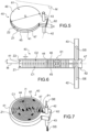
figure 5 représente, en perspective, un exemple de système de surchauffe des gaz d'un empilement à oxydes solides de type SOEC/SOFC conforme à l'invention, - la
figure 6 représente, selon une vue en coupe, le système de surchauffe de lafigure 5 , - la
figure 7 représente, en perspective, le système de surchauffe de lafigure 5 , sans la présence de plaques de fermeture, du côté de l'entrée des gaz, - la
figure 8 représente, en perspective, le système de surchauffe de lafigure 5 , sans la présence de plaques de fermeture, du côté de la sortie des gaz, - la
figure 9 illustre le trajet de soudage par transparence à suivre pour la fixation des plaques de fermeture au corps principal du système de surchauffe de lafigure 5 , - la
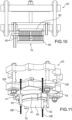
figure 10 représente, selon une vue en coupe, un exemple d'empilement à oxydes solides de type SOEC/SOFC comprenant des corps chauffants de part et d'autre d'une pluralité de systèmes de surchauffe tels que celui de lafigure 5 , et - la
figure 11 illustre, en perspective, un autre exemple d'empilement à oxydes solides de type SOEC/SOFC comprenant un corps chauffant au contact d'une pluralité de systèmes de surchauffe tels que celui de lafigure 5 pour deux lignes de gaz. - Dans l'ensemble de ces figures, des références identiques peuvent désigner des éléments identiques ou analogues.
- De plus, les différentes parties représentées sur les figures ne le sont pas nécessairement selon une échelle uniforme, pour rendre les figures plus lisibles.
- Les
figures 1 à 4 ont déjà été décrites précédemment dans la partie relative à l'état de la technique antérieure et au contexte technique de l'invention. Il est précisé que, pour lesfigures 1 et 2 , les symboles et les flèches d'alimentation de vapeur d'eau H2O, de distribution et de récupération de dihydrogène H2, d'oxygène O2, d'air et du courant électrique, sont montrés à des fins de clarté et de précision, pour illustrer le fonctionnement des dispositifs représentés. - En outre, il faut noter que tous les constituants (anode/électrolyte/cathode) d'une cellule électrochimique donnée sont préférentiellement des céramiques. La température de fonctionnement d'un empilement de type SOEC/SOFC haute température est par ailleurs typiquement comprise entre 600 et 1000°C.
- De plus, les termes éventuels « supérieur » et « inférieur » sont à comprendre ici selon le sens d'orientation normal d'un empilement de type SOEC/SOFC lorsque dans sa configuration d'utilisation.
- En référence aux
figures 5 à 11 , on a illustré un principe de réalisation d'un système de surchauffe 40 d'un empilement 20 conforme à l'invention. Ce système de surchauffe 40 permet de réaliser un chauffage des gaz en entrée d'un empilement 20 de type SOEC/SOFC associé à un four 10, comme décrit précédemment en référence à lafigure 3 . - Parmi les différents modes de transfert de chaleur dans la zone du four 10, le mode prépondérant à ces niveaux de température, soit entre 650 et 800°C, correspond à des échanges radiatifs par rayonnement. L'autre mode de transfert est alors la conduction thermique, et c'est celui que l'invention met en oeuvre car il a l'avantage de créer moins de pertes thermiques vers l'extérieur. Il s'agit du mode de transfert de chaleur provoqué par une différence de température entre deux régions d'un même milieu ou entre deux milieux en contact sans déplacement appréciable de matière. L'utilisation de plaques chauffantes, comme décrit par la suite, pour le système de surchauffe 40 permet de récupérer la conduction thermique et d'élever les gaz à la bonne température.
- Comme visible sur les
figures 1 à 8 , le système de surchauffe 40 des gaz GS en entrée de l'empilement 20 à oxydes solides de type SOEC/SOFC comporte tout d'abord un corps principal 41 sous la forme d'un bloc central 41. - Ce bloc central 41 forme un système compact qui se présente ici sous une forme cylindrique de section circulaire, avec un diamètre D d'environ 140 mm et une hauteur H d'environ 22 mm, comme visibles sur la
figure 5 . - Ce bloc central 41 est par exemple réalisé en superalliage à base de nickel, en particulier de type Inconel 600.
- Comme visible sur la
figure 6 , le bloc central 41 comporte une première zone Z1, dite zone inférieure, d'entrée des gaz à réchauffer GE et une deuxième zone Z2, dite zone supérieure, de sortie des gaz réchauffés GS. - Ces zones inférieure Z1 et supérieure Z2 sont séparées par un plan médian transversal M du bloc central 41.
- Par ailleurs, le système de surchauffe 40 comporte également un conduit d'entrée 42 des gaz à réchauffer GE communiquant avec la zone inférieure Z1 du bloc central 41, et un conduit de sortie 43 des gaz réchauffés GS communiquant avec la zone supérieure Z2 du bloc central 41.
- Comme tout particulièrement visible sur la
figure 6 , ces première Z1 et deuxième Z2 zones comportent respectivement un premier circuit de circulation des gaz C1 et un deuxième circuit de circulation des gaz C2. - De façon avantageuse, chaque circuit de circulation des gaz C1, C2 s'étend sous la forme d'une spirale, ici circulaire, respectivement depuis une première extrémité externe P1 vers une première extrémité interne I1, et depuis une deuxième extrémité externe P2 vers une deuxième extrémité interne I2.
- Ces première I1 et deuxième I2 extrémités internes communiquent entre elles par le biais d'un passage traversant 44 du bloc central 41, qui est formé au travers du plan médian M pour la mise en communication fluidique des première Z1 et deuxième Z2 zones.
- Par ailleurs, comme visible toujours sur la
figure 6 , les conduits d'entrée 42 et de sortie 43 sont respectivement en communication fluidique avec les première P1 et deuxième P2 extrémités externes. - De cette façon, comme illustré par le cheminement des flèches sur les
figures 6, 7 et8 , un flux de gaz à réchauffer GE entrant dans le conduit d'entrée 42 circule dans le premier circuit de circulation des gaz C1, depuis la première extrémité externe P1 vers la première extrémité interne I1, et traverse le passage traversant 44 pour ensuite circuler dans le deuxième circuit de circulation des gaz C2, depuis la deuxième extrémité interne I2 vers la deuxième extrémité externe P2, et ensuite dans le conduit de sortie 43 des gaz réchauffés GS pour atteindre enfin l'entrée de l'empilement 20 à oxydes solides de type SOEC/SOFC. - Par ailleurs, comme visible sur les
figures 5 et 6 , le système de surchauffe 40 comporte deux tôles de fermeture 45 et 46, s'étendant de part et d'autre du bloc central 41. Plus précisément, le premier circuit de circulation des gaz C1 est situé entre le plan médian M et la tôle de fermeture 45 et le deuxième circuit de circulation des gaz C2 est situé entre le plan médian M et la tôle de fermeture 46. - En outre, les premier C1 et deuxième C2 circuits de circulation des gaz sont formés par usinage, par exemple par le biais d'une fraiseuse à commande numérique ou de tout autre système d'usinage approprié afin d'obtenir une spirale. Cet usinage est réalisé suivant une spirale convergeant vers le centre du bloc central 41 au niveau du passage traversant 44.
- La profondeur f de l'usinage, représentée sur la
figure 6 , est par exemple d'environ 10 mm, tandis que la largeur l de l'usinage, représentée sur lafigure 6 également, est par exemple d'environ 3 mm. Avantageusement, la section de l'usinage équivaut à la section couverte par le diamètre interne d'un tube en inconel 600 de diamètre 10/12. De façon générale, la section de la spirale formée correspond préférentiellement à la quantité de gaz souhaitée pour l'alimentation de l'empilement 20. - Par ailleurs, comme visible sur les
figures 5 à 8 , il est à noter que les conduits d'entrée 42 et de sortie 43 s'étendent perpendiculairement au plan médian M en superposition l'un par rapport à l'autre et sont séparés l'un de l'autre par une paroi médiane transversale 47 du bloc central 41 dans laquelle est formé le passage traversant 44. - En outre, le bloc central 41 comporte une portion principale 61, comprenant les premier C1 et deuxième C2 circuits de circulation des gaz, et une portion latérale 62 en saillie de la portion principale 62 au niveau de laquelle les conduits d'entrée 42 et de sortie 43 sont connectés fluidiquement au bloc central 41.
- Les gaz entrants GE, en provenance d'échangeurs thermiques, pénètrent dans la première spirale du premier circuit C1 et convergent vers le centre du bloc central 41 jusqu'au passage traversant 44 sur une longueur totale d'environ 1,8 m. De là, les gaz franchissent le plan médian M par le biais du passage traversant 44 et suivent un chemin inverse dans la deuxième spirale du deuxième circuit C2 pour parcourir une longueur totale d'environ 1, 8 m également.
- Les tôles de fermeture 45 et 46 sont préférentiellement rapportées soudées laser par transparence. La technique du soudage au laser permet le soudage de métaux par les caractéristiques de la technologie laser : avec la haute densité d'énergie et de finesse du faisceau laser, les zones ciblées entrent en fusion puis sont rapidement soudées par refroidissement. Il en résulte une soudure solide sur une surface réduite.
- Comme illustré sur la
figure 9 , la soudure laser par transparence doit préférentiellement suivre le contour C tel que représenté pour pouvoir forcer les gaz à suivre le chemin complet. - Par ailleurs, il est possible de doubler le système de surchauffe 40 précédemment décrit pour une pluralité de lignes de gaz. Ainsi, les
figures 10 et 11 illustrent des exemples d'empilements 20 à oxydes solides de type SOEC/SOFC comprenant un ensemble 70 de deux systèmes de surchauffe 40 des gaz GS en entrée de l'empilement 20 associés à des corps chauffants 80 sous forme de plaques chauffantes 80. - Plus précisément, sur la
figure 10 , deux plaques chauffantes 80 sont situées de part et d'autre de deux systèmes de surchauffe 40 de telle sorte qu'ils soient pris en sandwich par les plaques chauffantes 80. Ces plaques chauffantes 80, au contact des systèmes de surchauffe 40, permettent le réchauffement des gaz par convection thermique avant leur entrée dans l'empilement 20. - Sur la
figure 11 , l'ensemble 70 comporte une plaque chauffante 80 de forme similaire à celle du bloc central 41. - Bien entendu, l'invention n'est pas limitée à l'exemple de réalisation qui vient d'être décrit. Diverses modifications peuvent y être apportées par l'homme du métier dans le cadre défini par les revendications.
Claims (11)
- Empilement (20) à oxydes solides de type SOEC/SOFC, caractérisé en ce qu'il comporte un ensemble (70) comportant :- au moins un système de surchauffe (40) des gaz (GS) en entrée de l'empilement (20) à oxydes solides de type SOEC/SOFC, comportant :- un corps principal (41) comprenant une première zone (Z1), dite zone inférieure, d'entrée des gaz à réchauffer (GE) et une deuxième zone (Z2), dite zone supérieure, de sortie des gaz réchauffés (GS), les première (Z1) et deuxième (Z2) zones étant séparées par un plan médian transversal (M) du corps principal (41),- au moins un conduit d'entrée (42) des gaz à réchauffer (GE) communiquant avec la première zone (Z1) du corps principal (41),- au moins un conduit de sortie (43) des gaz réchauffés (GS) communiquant avec la deuxième zone (Z2) du corps principal (41),les première (Z1) et deuxième (Z2) zones du corps principal (41) comportant respectivement un premier circuit de circulation des gaz (C1) et un deuxième circuit de circulation des gaz (C2), le premier circuit de circulation des gaz (C1), respectivement le deuxième circuit de circulation des gaz (C2), s'étendant sous la forme d'une spirale depuis une première extrémité externe (P1) vers une première extrémité interne (I1), respectivement depuis une deuxième extrémité externe (P2) vers une deuxième extrémité interne (I2),les première (l1) et deuxième (l2) extrémités internes communiquant entre elles par le biais d'un passage traversant (44) du corps principal (41), formé au travers du plan médian (M) du corps principal (41) pour la mise en communication fluidique des première (Z1) et deuxième (Z2) zones,les au moins un conduit d'entrée (42) et un conduit de sortie (43) étant respectivement en communication fluidique avec les première (P1) et deuxième (P2) extrémités externes de sorte qu'un flux de gaz à réchauffer (GE) entrant dans le au moins un conduit d'entrée (42) circule dans le premier circuit de circulation des gaz (C1), depuis la première extrémité externe (P1) vers la première extrémité interne (l1), et traverse le passage traversant (44) pour ensuite circuler dans le deuxième circuit de circulation des gaz (C2), depuis la deuxième extrémité interne (I2) vers la deuxième extrémité externe (P2), et ensuite dans le au moins un conduit de sortie (43) des gaz réchauffés (GS) pour atteindre l'entrée de l'empilement (20) à oxydes solides de type SOEC/SOFC,- au moins un corps chauffant (80) placé au contact dudit au moins un système de surchauffe (40) des gaz (GS).
- Empilement selon la revendication 1, caractérisé en ce que le système de surchauffe (40) comporte une première plaque de fermeture (45) et une deuxième plaque de fermeture (46), s'étendant de part et d'autre du corps principal (41) pour respectivement recouvrir les première (Z1) et deuxième (Z2) zones du corps principal (41), le premier circuit de circulation des gaz (C1) étant alors situé entre le plan médian (M) et la première plaque de fermeture (45) et le deuxième circuit de circulation des gaz (C2) étant alors situé entre le plan médian (M) et la deuxième plaque de fermeture (46).
- Empilement selon la revendication 1 ou 2, caractérisé en ce que les au moins un conduit d'entrée (42) et un conduit de sortie (43) s'étendent sensiblement perpendiculairement au plan médian (M) du corps principal (41) en superposition l'un par rapport à l'autre et étant séparés l'un de l'autre par une paroi médiane transversale (47) du corps principal (41) dans laquelle est formé le passage traversant (44).
- Empilement selon l'une des revendications précédentes, caractérisé en ce que le corps principal (41) présente une forme générale cylindrique, notamment de section circulaire, les premier (C1) et deuxième (C2) circuits de circulation des gaz s'étendant notamment chacun sous la forme d'une spirale circulaire.
- Empilement selon l'une quelconque des revendications précédentes, caractérisé en ce que le corps principal (41) comporte une portion principale (61), comprenant les premier (C1) et deuxième (C2) circuits de circulation des gaz, et une portion latérale (62) en saillie de la portion principale (62) au niveau de laquelle les au moins un conduit d'entrée (42) et un conduit de sortie (43) sont connectés fluidiquement au corps principal (41).
- Empilement selon l'une quelconque des revendications précédentes, caractérisé en ce que le corps principal (41) est réalisé en superalliage à base de nickel, en particulier de type Inconel 600.
- Empilement selon l'une quelconque des revendications précédentes, caractérisé en ce que l'ensemble (70) comporte au moins deux corps chauffants (80) disposés de part et d'autre du au moins un système de surchauffe (40) des gaz (GS).
- Empilement selon l'une quelconque des revendications précédentes, caractérisé en ce que l'ensemble (70) comporte au moins deux systèmes de surchauffe (40) des gaz (GS), au contact l'un de l'autre, et au moins deux corps chauffants (80) prenant en sandwich les au moins deux systèmes de surchauffe (40) des gaz (GS).
- Empilement selon l'une quelconque des revendications précédentes, caractérisé en ce qu'au moins un corps chauffant (80) présente une forme générale sensiblement analogue à celle d'au moins un système de surchauffe (40) des gaz (GS).
- Procédé de fabrication d'au moins un système de surchauffe (40) des gaz (GS) en entrée de l'empilement (20) à oxydes solides de type SOEC/SOFC selon l'une quelconque des revendications précédentes, caractérisé en ce qu'il comporte l'étape d'usinage du corps principal (41) pour former le premier circuit de circulation des gaz (C1) et le deuxième circuit de circulation des gaz (C2).
- Procédé selon la revendication 10, caractérisé en ce qu'il comporte l'étape consistant à rapporter, par un procédé de soudage au laser par transparence, une première plaque de fermeture (45) et une deuxième plaque de fermeture (46) de part et d'autre du corps principal (41) pour respectivement recouvrir les première (Z1) et deuxième (Z2) zones du corps principal (41).
Applications Claiming Priority (2)
| Application Number | Priority Date | Filing Date | Title |
|---|---|---|---|
| FR1750099A FR3061496B1 (fr) | 2017-01-05 | 2017-01-05 | Systeme de surchauffe des gaz en entree d'un empilement a oxydes solides de type soec/sofc |
| PCT/FR2017/053850 WO2018127649A1 (fr) | 2017-01-05 | 2017-12-27 | Système de surchauffe des gaz en entrée d'un empilement à oxydes solides de type soec/sofc |
Publications (2)
| Publication Number | Publication Date |
|---|---|
| EP3565917A1 EP3565917A1 (fr) | 2019-11-13 |
| EP3565917B1 true EP3565917B1 (fr) | 2023-08-16 |
Family
ID=58401847
Family Applications (1)
| Application Number | Title | Priority Date | Filing Date |
|---|---|---|---|
| EP17832304.4A Active EP3565917B1 (fr) | 2017-01-05 | 2017-12-27 | Système de surchauffe des gaz en entrée d'un empilement à oxydes solides de type soec/sofc |
Country Status (7)
| Country | Link |
|---|---|
| US (1) | US11228047B2 (fr) |
| EP (1) | EP3565917B1 (fr) |
| JP (1) | JP7039600B2 (fr) |
| CA (1) | CA3048880A1 (fr) |
| DK (1) | DK3565917T3 (fr) |
| FR (1) | FR3061496B1 (fr) |
| WO (1) | WO2018127649A1 (fr) |
Families Citing this family (10)
| Publication number | Priority date | Publication date | Assignee | Title |
|---|---|---|---|---|
| FR3073093B1 (fr) | 2017-10-26 | 2022-02-04 | Commissariat Energie Atomique | Ensemble d'un empilement a oxydes solides de type soec/sofc et d'un systeme de serrage avec systeme de surchauffe des gaz integre |
| FR3075481B1 (fr) | 2017-12-19 | 2020-01-10 | Commissariat A L'energie Atomique Et Aux Energies Alternatives | Ensemble d'un empilement a oxydes solides de type soec/sofc, d'un systeme de serrage et d'un systeme de couplage etanche |
| USD887538S1 (en) * | 2018-07-03 | 2020-06-16 | Economico, Llc | Water heater insert |
| FR3088773B1 (fr) * | 2018-11-16 | 2020-12-25 | Commissariat Energie Atomique | Dispositif electrochimique a oxydes solides pourvu d'un moyen de surchauffe integre compact |
| FR3096057B1 (fr) | 2019-05-13 | 2021-06-11 | Commissariat Energie Atomique | Procede de fabrication d’une piece en alliage d’aluminium par fabrication additive |
| FR3116014B1 (fr) | 2020-11-10 | 2022-10-14 | Commissariat Energie Atomique | PROCEDE DE FABRICATION D’UNE PIECE EN ALLIAGE D’ALUMINIUM PAR FABRICATION ADDITIVE A PARTIR D’UN MELANGE DE POUDRES CONTENANT DES PARTICULES DE ZrSi2 |
| US12040520B2 (en) * | 2022-07-07 | 2024-07-16 | Bloom Energy Corporation | Integrated SOEC building block (SBB) |
| WO2024028634A1 (fr) * | 2022-08-02 | 2024-02-08 | Arcelormittal | Procédé de chauffage d'un four |
| US12504203B2 (en) | 2023-02-10 | 2025-12-23 | EnhancedGEO Holdings, LLC | Reverse-flow magma-based geothermal generation |
| WO2025162556A1 (fr) * | 2024-01-30 | 2025-08-07 | L'air Liquide, Societe Anonyme Pour L'etude Et L'exploitation Des Procedes Georges Claude | Procédé de récupération de chaleur de gaz de combustion et système associé |
Family Cites Families (17)
| Publication number | Priority date | Publication date | Assignee | Title |
|---|---|---|---|---|
| US1654551A (en) * | 1924-12-20 | 1928-01-03 | Schutte & Koerting Co | Fluid-heating device |
| US1833664A (en) * | 1927-11-10 | 1931-11-24 | Internat Bitumenoil Corp | Condenser |
| DE3374537D1 (en) * | 1982-09-24 | 1987-12-23 | Onofrio Rocchitelli | Heating device for the glass washing fluid of motor vehicles and the like |
| US4687907A (en) * | 1985-06-07 | 1987-08-18 | Pace, Incorporated | Heater device |
| MY110237A (en) * | 1987-05-25 | 1998-03-31 | Dunham Bush International Cayman Ltd | Improved method of manufacturing heat exchangers |
| JP2001227420A (ja) | 2000-02-17 | 2001-08-24 | Noriyuki Hara | 熱交換器 |
| WO2002054519A1 (fr) | 2000-12-28 | 2002-07-11 | Mitsubishi Materials Corporation | Module de pile a combustible et structure pour l'alimentation en gaz de cette pile a combustible |
| US6889005B2 (en) | 2003-04-04 | 2005-05-03 | Valeo Electrical Systems, Inc. | Fluid heater with compressible cover freeze protection |
| US20050005592A1 (en) | 2003-07-07 | 2005-01-13 | Fielder William Sheridan | Hollow turbine |
| US20070029369A1 (en) * | 2005-08-02 | 2007-02-08 | United Technologies Corporation | Transient liquid phase bonding of dissimilar metals |
| CN101191612A (zh) * | 2006-11-20 | 2008-06-04 | 游图明 | 用于家用电器的蒸汽形成方法及装置 |
| US8120915B2 (en) * | 2008-08-18 | 2012-02-21 | General Electric Company | Integral heat sink with spiral manifolds |
| US20100316919A1 (en) * | 2009-06-15 | 2010-12-16 | Adaptive Materials, Inc. | Fuel cell stack with heat recuperator |
| DE102010020265A1 (de) * | 2010-05-11 | 2011-11-17 | Siemens Aktiengesellschaft | Verfahren zur Erzeugung von Wasserstoff aus Wasser mittels eines Hochtemperatur-Elektrolyseurs |
| CN102404973A (zh) * | 2010-09-10 | 2012-04-04 | 奇鋐科技股份有限公司 | 热交换器结构 |
| JP5725048B2 (ja) * | 2013-01-18 | 2015-05-27 | 株式会社デンソー | 燃料電池装置 |
| US20150075754A1 (en) * | 2013-09-17 | 2015-03-19 | Ge Aviation Systems Llc | Single-pass cold plate assembly |
-
2017
- 2017-01-05 FR FR1750099A patent/FR3061496B1/fr not_active Expired - Fee Related
- 2017-12-27 DK DK17832304.4T patent/DK3565917T3/da active
- 2017-12-27 EP EP17832304.4A patent/EP3565917B1/fr active Active
- 2017-12-27 US US16/475,836 patent/US11228047B2/en active Active
- 2017-12-27 WO PCT/FR2017/053850 patent/WO2018127649A1/fr not_active Ceased
- 2017-12-27 CA CA3048880A patent/CA3048880A1/fr active Pending
- 2017-12-27 JP JP2019536081A patent/JP7039600B2/ja active Active
Also Published As
| Publication number | Publication date |
|---|---|
| FR3061496B1 (fr) | 2019-05-31 |
| JP2020515710A (ja) | 2020-05-28 |
| JP7039600B2 (ja) | 2022-03-22 |
| WO2018127649A1 (fr) | 2018-07-12 |
| US11228047B2 (en) | 2022-01-18 |
| FR3061496A1 (fr) | 2018-07-06 |
| EP3565917A1 (fr) | 2019-11-13 |
| CA3048880A1 (fr) | 2018-07-12 |
| US20190372137A1 (en) | 2019-12-05 |
| DK3565917T3 (da) | 2023-10-09 |
Similar Documents
| Publication | Publication Date | Title |
|---|---|---|
| EP3565917B1 (fr) | Système de surchauffe des gaz en entrée d'un empilement à oxydes solides de type soec/sofc | |
| EP3679620B1 (fr) | Ensemble d'un empilement à oxydes solides de type soec/sofc et d'un système de serrage avec système de surchauffe des gaz intégré | |
| EP3183379B1 (fr) | Procédé d'électrolyse ou de co-électrolyse à haute température, procédé de production d'électricité par pile à combustible sofc, interconnecteurs, réacteurs et procédés de fonctionnement associés | |
| EP3707296B1 (fr) | Ensemble d'un empilement à oxydes solides de type soec/sofc, d'un système de serrage et d'un système de couplage étanche | |
| EP3562972B1 (fr) | Système de couplage étanche à haute température d'un empilement à oxydes solides de type soec/sofc | |
| EP4315462B1 (fr) | Procédé de réalisation d'un empilement à oxydes solides de type soec/sofc et empilement associé | |
| EP3673529B1 (fr) | Ensemble d'un empilement à oxydes solides de type soec/sofc et d'un système de serrage intégrant un système d'échange thermique | |
| EP4013981B1 (fr) | Ensemble d'un empilement à oxydes solides de type soec/sofc et d'un système de couplage étanche à haute température | |
| EP3835455B1 (fr) | Plaque de serrage integrant un organe chauffant et dispositif electrochimique le comportant | |
| FR3094843A1 (fr) | Ensemble d’un empilement à oxydes solides de type SOEC/SOFC et d’un système de serrage intégrant un système de distribution de gaz | |
| CA3231282C (fr) | Ensemble d'un empilement de cellules a oxydes solides de type soec/sofc et d'un systeme de serrage avec plaque chauffante | |
| CA3230063C (fr) | Interconnecteur pour empilement de cellules a oxydes solides de type soec/sofc comportant des elements en relief differents | |
| EP4092163B1 (fr) | Ensemble d'un empilement à oxydes solides de type soec/sofc et d'un système de couplage étanche à haute température avec bride de couplage | |
| EP4388147B1 (fr) | Interconnecteur pour empilement de cellules à oxydes solides de type soec/sofc comportant des éléments en relief différents | |
| WO2025247777A1 (fr) | Ensemble comportant une pluralité d'empilements à oxydes solides de type soec/sofc à haute température et un bypass |
Legal Events
| Date | Code | Title | Description |
|---|---|---|---|
| STAA | Information on the status of an ep patent application or granted ep patent |
Free format text: STATUS: UNKNOWN |
|
| STAA | Information on the status of an ep patent application or granted ep patent |
Free format text: STATUS: THE INTERNATIONAL PUBLICATION HAS BEEN MADE |
|
| PUAI | Public reference made under article 153(3) epc to a published international application that has entered the european phase |
Free format text: ORIGINAL CODE: 0009012 |
|
| STAA | Information on the status of an ep patent application or granted ep patent |
Free format text: STATUS: REQUEST FOR EXAMINATION WAS MADE |
|
| 17P | Request for examination filed |
Effective date: 20190708 |
|
| AK | Designated contracting states |
Kind code of ref document: A1 Designated state(s): AL AT BE BG CH CY CZ DE DK EE ES FI FR GB GR HR HU IE IS IT LI LT LU LV MC MK MT NL NO PL PT RO RS SE SI SK SM TR |
|
| AX | Request for extension of the european patent |
Extension state: BA ME |
|
| DAV | Request for validation of the european patent (deleted) | ||
| DAX | Request for extension of the european patent (deleted) | ||
| STAA | Information on the status of an ep patent application or granted ep patent |
Free format text: STATUS: EXAMINATION IS IN PROGRESS |
|
| 17Q | First examination report despatched |
Effective date: 20220214 |
|
| REG | Reference to a national code |
Ref country code: DE Free format text: PREVIOUS MAIN CLASS: C25B0015020000 Ref country code: DE Ref legal event code: R079 Ref document number: 602017072885 Country of ref document: DE Free format text: PREVIOUS MAIN CLASS: C25B0015020000 Ipc: C25B0015021000 |
|
| GRAP | Despatch of communication of intention to grant a patent |
Free format text: ORIGINAL CODE: EPIDOSNIGR1 |
|
| STAA | Information on the status of an ep patent application or granted ep patent |
Free format text: STATUS: GRANT OF PATENT IS INTENDED |
|
| RIC1 | Information provided on ipc code assigned before grant |
Ipc: H01M 8/12 20060101ALI20230216BHEP Ipc: F28D 21/00 20060101ALI20230216BHEP Ipc: C25B 9/73 20210101ALI20230216BHEP Ipc: H01M 8/2425 20160101ALI20230216BHEP Ipc: F28D 7/04 20060101ALI20230216BHEP Ipc: F24H 1/16 20060101ALI20230216BHEP Ipc: H01M 8/04007 20160101ALI20230216BHEP Ipc: C25B 9/67 20210101ALI20230216BHEP Ipc: C25B 15/021 20210101AFI20230216BHEP |
|
| INTG | Intention to grant announced |
Effective date: 20230320 |
|
| P01 | Opt-out of the competence of the unified patent court (upc) registered |
Effective date: 20230518 |
|
| GRAS | Grant fee paid |
Free format text: ORIGINAL CODE: EPIDOSNIGR3 |
|
| GRAA | (expected) grant |
Free format text: ORIGINAL CODE: 0009210 |
|
| STAA | Information on the status of an ep patent application or granted ep patent |
Free format text: STATUS: THE PATENT HAS BEEN GRANTED |
|
| AK | Designated contracting states |
Kind code of ref document: B1 Designated state(s): AL AT BE BG CH CY CZ DE DK EE ES FI FR GB GR HR HU IE IS IT LI LT LU LV MC MK MT NL NO PL PT RO RS SE SI SK SM TR |
|
| REG | Reference to a national code |
Ref country code: GB Ref legal event code: FG4D Free format text: NOT ENGLISH |
|
| REG | Reference to a national code |
Ref country code: CH Ref legal event code: EP Ref country code: DE Ref legal event code: R096 Ref document number: 602017072885 Country of ref document: DE |
|
| REG | Reference to a national code |
Ref country code: IE Ref legal event code: FG4D Free format text: LANGUAGE OF EP DOCUMENT: FRENCH |
|
| REG | Reference to a national code |
Ref country code: DK Ref legal event code: T3 Effective date: 20231002 |
|
| 111L | Licence recorded |
Designated state(s): AL AT BE BG CH CY CZ DE DK EE ES FI FR GB GR HR HU IE IS IT LT LU LV MC MK MT NL NO PL PT RO RS SE SI SK SM TR Name of requester: GENVIA, FR Effective date: 20230522 |
|
| REG | Reference to a national code |
Ref country code: LT Ref legal event code: MG9D |
|
| REG | Reference to a national code |
Ref country code: NL Ref legal event code: MP Effective date: 20230816 |
|
| REG | Reference to a national code |
Ref country code: AT Ref legal event code: MK05 Ref document number: 1600133 Country of ref document: AT Kind code of ref document: T Effective date: 20230816 |
|
| PG25 | Lapsed in a contracting state [announced via postgrant information from national office to epo] |
Ref country code: GR Free format text: LAPSE BECAUSE OF FAILURE TO SUBMIT A TRANSLATION OF THE DESCRIPTION OR TO PAY THE FEE WITHIN THE PRESCRIBED TIME-LIMIT Effective date: 20231117 |
|
| PG25 | Lapsed in a contracting state [announced via postgrant information from national office to epo] |
Ref country code: IS Free format text: LAPSE BECAUSE OF FAILURE TO SUBMIT A TRANSLATION OF THE DESCRIPTION OR TO PAY THE FEE WITHIN THE PRESCRIBED TIME-LIMIT Effective date: 20231216 |
|
| PG25 | Lapsed in a contracting state [announced via postgrant information from national office to epo] |
Ref country code: SE Free format text: LAPSE BECAUSE OF FAILURE TO SUBMIT A TRANSLATION OF THE DESCRIPTION OR TO PAY THE FEE WITHIN THE PRESCRIBED TIME-LIMIT Effective date: 20230816 Ref country code: RS Free format text: LAPSE BECAUSE OF FAILURE TO SUBMIT A TRANSLATION OF THE DESCRIPTION OR TO PAY THE FEE WITHIN THE PRESCRIBED TIME-LIMIT Effective date: 20230816 Ref country code: PT Free format text: LAPSE BECAUSE OF FAILURE TO SUBMIT A TRANSLATION OF THE DESCRIPTION OR TO PAY THE FEE WITHIN THE PRESCRIBED TIME-LIMIT Effective date: 20231218 Ref country code: NO Free format text: LAPSE BECAUSE OF FAILURE TO SUBMIT A TRANSLATION OF THE DESCRIPTION OR TO PAY THE FEE WITHIN THE PRESCRIBED TIME-LIMIT Effective date: 20231116 Ref country code: NL Free format text: LAPSE BECAUSE OF FAILURE TO SUBMIT A TRANSLATION OF THE DESCRIPTION OR TO PAY THE FEE WITHIN THE PRESCRIBED TIME-LIMIT Effective date: 20230816 Ref country code: LV Free format text: LAPSE BECAUSE OF FAILURE TO SUBMIT A TRANSLATION OF THE DESCRIPTION OR TO PAY THE FEE WITHIN THE PRESCRIBED TIME-LIMIT Effective date: 20230816 Ref country code: LT Free format text: LAPSE BECAUSE OF FAILURE TO SUBMIT A TRANSLATION OF THE DESCRIPTION OR TO PAY THE FEE WITHIN THE PRESCRIBED TIME-LIMIT Effective date: 20230816 Ref country code: IS Free format text: LAPSE BECAUSE OF FAILURE TO SUBMIT A TRANSLATION OF THE DESCRIPTION OR TO PAY THE FEE WITHIN THE PRESCRIBED TIME-LIMIT Effective date: 20231216 Ref country code: HR Free format text: LAPSE BECAUSE OF FAILURE TO SUBMIT A TRANSLATION OF THE DESCRIPTION OR TO PAY THE FEE WITHIN THE PRESCRIBED TIME-LIMIT Effective date: 20230816 Ref country code: GR Free format text: LAPSE BECAUSE OF FAILURE TO SUBMIT A TRANSLATION OF THE DESCRIPTION OR TO PAY THE FEE WITHIN THE PRESCRIBED TIME-LIMIT Effective date: 20231117 Ref country code: FI Free format text: LAPSE BECAUSE OF FAILURE TO SUBMIT A TRANSLATION OF THE DESCRIPTION OR TO PAY THE FEE WITHIN THE PRESCRIBED TIME-LIMIT Effective date: 20230816 Ref country code: AT Free format text: LAPSE BECAUSE OF FAILURE TO SUBMIT A TRANSLATION OF THE DESCRIPTION OR TO PAY THE FEE WITHIN THE PRESCRIBED TIME-LIMIT Effective date: 20230816 |
|
| PG25 | Lapsed in a contracting state [announced via postgrant information from national office to epo] |
Ref country code: PL Free format text: LAPSE BECAUSE OF FAILURE TO SUBMIT A TRANSLATION OF THE DESCRIPTION OR TO PAY THE FEE WITHIN THE PRESCRIBED TIME-LIMIT Effective date: 20230816 |
|
| PG25 | Lapsed in a contracting state [announced via postgrant information from national office to epo] |
Ref country code: ES Free format text: LAPSE BECAUSE OF FAILURE TO SUBMIT A TRANSLATION OF THE DESCRIPTION OR TO PAY THE FEE WITHIN THE PRESCRIBED TIME-LIMIT Effective date: 20230816 |
|
| PG25 | Lapsed in a contracting state [announced via postgrant information from national office to epo] |
Ref country code: SM Free format text: LAPSE BECAUSE OF FAILURE TO SUBMIT A TRANSLATION OF THE DESCRIPTION OR TO PAY THE FEE WITHIN THE PRESCRIBED TIME-LIMIT Effective date: 20230816 Ref country code: RO Free format text: LAPSE BECAUSE OF FAILURE TO SUBMIT A TRANSLATION OF THE DESCRIPTION OR TO PAY THE FEE WITHIN THE PRESCRIBED TIME-LIMIT Effective date: 20230816 Ref country code: ES Free format text: LAPSE BECAUSE OF FAILURE TO SUBMIT A TRANSLATION OF THE DESCRIPTION OR TO PAY THE FEE WITHIN THE PRESCRIBED TIME-LIMIT Effective date: 20230816 Ref country code: EE Free format text: LAPSE BECAUSE OF FAILURE TO SUBMIT A TRANSLATION OF THE DESCRIPTION OR TO PAY THE FEE WITHIN THE PRESCRIBED TIME-LIMIT Effective date: 20230816 Ref country code: CZ Free format text: LAPSE BECAUSE OF FAILURE TO SUBMIT A TRANSLATION OF THE DESCRIPTION OR TO PAY THE FEE WITHIN THE PRESCRIBED TIME-LIMIT Effective date: 20230816 Ref country code: SK Free format text: LAPSE BECAUSE OF FAILURE TO SUBMIT A TRANSLATION OF THE DESCRIPTION OR TO PAY THE FEE WITHIN THE PRESCRIBED TIME-LIMIT Effective date: 20230816 |
|
| REG | Reference to a national code |
Ref country code: DE Ref legal event code: R097 Ref document number: 602017072885 Country of ref document: DE |
|
| PLBE | No opposition filed within time limit |
Free format text: ORIGINAL CODE: 0009261 |
|
| STAA | Information on the status of an ep patent application or granted ep patent |
Free format text: STATUS: NO OPPOSITION FILED WITHIN TIME LIMIT |
|
| 26N | No opposition filed |
Effective date: 20240517 |
|
| PG25 | Lapsed in a contracting state [announced via postgrant information from national office to epo] |
Ref country code: SI Free format text: LAPSE BECAUSE OF FAILURE TO SUBMIT A TRANSLATION OF THE DESCRIPTION OR TO PAY THE FEE WITHIN THE PRESCRIBED TIME-LIMIT Effective date: 20230816 |
|
| PG25 | Lapsed in a contracting state [announced via postgrant information from national office to epo] |
Ref country code: LU Free format text: LAPSE BECAUSE OF NON-PAYMENT OF DUE FEES Effective date: 20231227 |
|
| PG25 | Lapsed in a contracting state [announced via postgrant information from national office to epo] |
Ref country code: MC Free format text: LAPSE BECAUSE OF FAILURE TO SUBMIT A TRANSLATION OF THE DESCRIPTION OR TO PAY THE FEE WITHIN THE PRESCRIBED TIME-LIMIT Effective date: 20230816 |
|
| REG | Reference to a national code |
Ref country code: BE Ref legal event code: MM Effective date: 20231231 |
|
| PG25 | Lapsed in a contracting state [announced via postgrant information from national office to epo] |
Ref country code: MC Free format text: LAPSE BECAUSE OF FAILURE TO SUBMIT A TRANSLATION OF THE DESCRIPTION OR TO PAY THE FEE WITHIN THE PRESCRIBED TIME-LIMIT Effective date: 20230816 Ref country code: LU Free format text: LAPSE BECAUSE OF NON-PAYMENT OF DUE FEES Effective date: 20231227 |
|
| REG | Reference to a national code |
Ref country code: IE Ref legal event code: MM4A |
|
| PG25 | Lapsed in a contracting state [announced via postgrant information from national office to epo] |
Ref country code: IE Free format text: LAPSE BECAUSE OF NON-PAYMENT OF DUE FEES Effective date: 20231227 |
|
| PG25 | Lapsed in a contracting state [announced via postgrant information from national office to epo] |
Ref country code: BE Free format text: LAPSE BECAUSE OF NON-PAYMENT OF DUE FEES Effective date: 20231231 |
|
| PG25 | Lapsed in a contracting state [announced via postgrant information from national office to epo] |
Ref country code: IE Free format text: LAPSE BECAUSE OF NON-PAYMENT OF DUE FEES Effective date: 20231227 Ref country code: BE Free format text: LAPSE BECAUSE OF NON-PAYMENT OF DUE FEES Effective date: 20231231 |
|
| PG25 | Lapsed in a contracting state [announced via postgrant information from national office to epo] |
Ref country code: BG Free format text: LAPSE BECAUSE OF FAILURE TO SUBMIT A TRANSLATION OF THE DESCRIPTION OR TO PAY THE FEE WITHIN THE PRESCRIBED TIME-LIMIT Effective date: 20230816 |
|
| PG25 | Lapsed in a contracting state [announced via postgrant information from national office to epo] |
Ref country code: BG Free format text: LAPSE BECAUSE OF FAILURE TO SUBMIT A TRANSLATION OF THE DESCRIPTION OR TO PAY THE FEE WITHIN THE PRESCRIBED TIME-LIMIT Effective date: 20230816 |
|
| PG25 | Lapsed in a contracting state [announced via postgrant information from national office to epo] |
Ref country code: CY Free format text: LAPSE BECAUSE OF FAILURE TO SUBMIT A TRANSLATION OF THE DESCRIPTION OR TO PAY THE FEE WITHIN THE PRESCRIBED TIME-LIMIT; INVALID AB INITIO Effective date: 20171227 |
|
| PG25 | Lapsed in a contracting state [announced via postgrant information from national office to epo] |
Ref country code: HU Free format text: LAPSE BECAUSE OF FAILURE TO SUBMIT A TRANSLATION OF THE DESCRIPTION OR TO PAY THE FEE WITHIN THE PRESCRIBED TIME-LIMIT; INVALID AB INITIO Effective date: 20171227 |
|
| PG25 | Lapsed in a contracting state [announced via postgrant information from national office to epo] |
Ref country code: TR Free format text: LAPSE BECAUSE OF FAILURE TO SUBMIT A TRANSLATION OF THE DESCRIPTION OR TO PAY THE FEE WITHIN THE PRESCRIBED TIME-LIMIT Effective date: 20230816 |
|
| REG | Reference to a national code |
Ref country code: CH Ref legal event code: U11 Free format text: ST27 STATUS EVENT CODE: U-0-0-U10-U11 (AS PROVIDED BY THE NATIONAL OFFICE) Effective date: 20260101 |
|
| PGFP | Annual fee paid to national office [announced via postgrant information from national office to epo] |
Ref country code: GB Payment date: 20251229 Year of fee payment: 9 |
|
| PGFP | Annual fee paid to national office [announced via postgrant information from national office to epo] |
Ref country code: DK Payment date: 20251217 Year of fee payment: 9 |
|
| PGFP | Annual fee paid to national office [announced via postgrant information from national office to epo] |
Ref country code: FR Payment date: 20251222 Year of fee payment: 9 |
|
| PGFP | Annual fee paid to national office [announced via postgrant information from national office to epo] |
Ref country code: DE Payment date: 20251222 Year of fee payment: 9 |
|
| PGFP | Annual fee paid to national office [announced via postgrant information from national office to epo] |
Ref country code: IT Payment date: 20251231 Year of fee payment: 9 |
|
| PGFP | Annual fee paid to national office [announced via postgrant information from national office to epo] |
Ref country code: CH Payment date: 20260101 Year of fee payment: 9 |