EP3565751B1 - Switchover between element controllers in railway operation - Google Patents
Switchover between element controllers in railway operation Download PDFInfo
- Publication number
- EP3565751B1 EP3565751B1 EP18704927.5A EP18704927A EP3565751B1 EP 3565751 B1 EP3565751 B1 EP 3565751B1 EP 18704927 A EP18704927 A EP 18704927A EP 3565751 B1 EP3565751 B1 EP 3565751B1
- Authority
- EP
- European Patent Office
- Prior art keywords
- element controller
- controller
- operating mode
- interlocking
- master
- Prior art date
- Legal status (The legal status is an assumption and is not a legal conclusion. Google has not performed a legal analysis and makes no representation as to the accuracy of the status listed.)
- Active
Links
Images

Classifications
-
- B—PERFORMING OPERATIONS; TRANSPORTING
- B61—RAILWAYS
- B61L—GUIDING RAILWAY TRAFFIC; ENSURING THE SAFETY OF RAILWAY TRAFFIC
- B61L7/00—Remote control of local operating means for points, signals, or trackmounted scotch-blocks
- B61L7/06—Remote control of local operating means for points, signals, or trackmounted scotch-blocks using electrical transmission
- B61L7/08—Circuitry
- B61L7/088—Common line wire control using series of coded pulses
-
- B—PERFORMING OPERATIONS; TRANSPORTING
- B61—RAILWAYS
- B61L—GUIDING RAILWAY TRAFFIC; ENSURING THE SAFETY OF RAILWAY TRAFFIC
- B61L27/00—Central railway traffic control systems; Trackside control; Communication systems specially adapted therefor
- B61L27/30—Trackside multiple control systems, e.g. switch-over between different systems
- B61L27/33—Backup systems, e.g. switching when failures occur
-
- G—PHYSICS
- G05—CONTROLLING; REGULATING
- G05B—CONTROL OR REGULATING SYSTEMS IN GENERAL; FUNCTIONAL ELEMENTS OF SUCH SYSTEMS; MONITORING OR TESTING ARRANGEMENTS FOR SUCH SYSTEMS OR ELEMENTS
- G05B9/00—Safety arrangements
- G05B9/02—Safety arrangements electric
- G05B9/03—Safety arrangements electric with multiple-channel loop, i.e. redundant control systems
-
- B—PERFORMING OPERATIONS; TRANSPORTING
- B61—RAILWAYS
- B61L—GUIDING RAILWAY TRAFFIC; ENSURING THE SAFETY OF RAILWAY TRAFFIC
- B61L27/00—Central railway traffic control systems; Trackside control; Communication systems specially adapted therefor
- B61L27/70—Details of trackside communication
Definitions
- the invention relates to switching between element controllers in rail operations.
- the patent application DE 41 13 959 A1 discloses a device for monitoring an electronic control, with a first and second computer as well as at least one monitoring device assigned to one of the two computers and a switchover device connected to the two computers on the output side, which is connected to a control device, the monitoring device assigned to the first computer also on the output side an input of the second computer is connected to transmit signals.
- This cross-connection of the monitoring devices assigned to the computers ensures redundancy in the event of a fault or faulty signals.
- EP 1 118 917 A1 various embodiments of a servo control device are described.
- a reference control adjuster is connected to a master servo controller via a first connection and to a slave servo controller via a second connection, the output of the slave servo controller being fed to the controller instead of that of the master servo controller to the actuator, in the case of a detected error on the side of the master servo controller.
- An element controller also referred to as a control device on the track, is connected to an interlocking via at least one data link.
- the data connection can be of the Ethernet type, for example.
- the element controller provides local signal processing and is set up for the connection of railway actuators or sensors. In interaction with the actuators or sensors, it is possible, for example, to control switches and / or signals and / or read out track circles or axle counters. The element controller thus provides the interface between the interlocking and the railway actuators or sensors.
- the object of the invention is to achieve the above Avoid disadvantages and, in particular, provide an efficient and safe solution for dealing with such element controllers.
- first and the second element controller negotiate beforehand who is operated in the master operating mode and who is operated in the slave operating mode by transmitting a start message to the other element controller after a predetermined period of time and that element controller changes to the slave operating mode that receives this start message before it has sent a start message.
- the predetermined period of time is determined based on a random generator, a pseudo-random generator or based on a deterministic pattern.
- the element controller that changes to the slave operating mode informs the other element controller about this and the other element controller then changes to the master operating mode.
- the element controller communicates with an interlocking in the master operating mode and the element controller in the slave operating mode the communication of the element controller, which is in the master operating mode, monitors.
- the message or error message indicates, for example, a defect in the element controller.
- each of the element controllers has two interfaces, one of the interfaces being connected to the interlocking via a communication link and the first element controller and the second element controller being connected to one another via the other interface.
- the interface is an Ethernet interface and the communication link is an Ethernet link.
- an interlocking can control both a single element controller and a redundantly designed element controller.
- the redundancy circuit is relocated to this element controller.
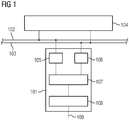
- Fig.1 shows a schematic arrangement in which an element controller 101 is connected to an interlocking 104 via two Ethernet connections 102, 103.
- the element controller 101 has two Ethernet interfaces 105, 106, the Ethernet interface 105 with the Ethernet connection 102 and the Ethernet interface 106 is connected to the Ethernet connection 103.
- the Ethernet controller 101 also has a communication unit 107 and a safety controller 108.
- the two Ethernet interfaces 105, 106 are connected to the communication unit 107.
- the communication unit 107 is also connected to the safety controller 108 and the safety controller 108 has a connection 109 to at least one actuator and / or at least one sensor.
- the interlocking 104 (essentially) simultaneously transmits an interlocking command to the element controller 101 via the Ethernet connections 102, 103 and the Ethernet interfaces 105, 106. There are thus two communication paths (Ethernet connection 102 with Ethernet interface 105 or Ethernet connection 103 with Ethernet interface 106) between the interlocking 104 and the element controller 101.
- the element controller 101 fails and the associated malfunctions occur.
- FIG. 4 shows a schematic diagram with two element controllers 201, 202, on the basis of which the fail-safety compared to the in Fig.1 example shown is increased.
- the element controller 201 is connected to the interlocking 205 via an Ethernet connection 203.
- the element controller 201 has two Ethernet interfaces 206, 207, the Ethernet interface 206 with the Ethernet connection 203 and the Ethernet interface 207 is connected to an Ethernet interface 211 of the Ethernet controller 202. This (direct) connection is also referenced with the reference number 218.
- the Ethernet controller 201 also has a communication unit 208 and a safety controller 209. The two Ethernet interfaces 206, 207 are connected to the communication unit 208. The communication unit 208 is also connected to the safety controller 209.
- the safety controller 209 is connected to a redundancy selection unit 210 (also referred to as a selection circuit) and the redundancy selection unit 210 has a connection 217 to at least one actuator and / or at least one sensor.
- a redundancy selection unit 210 also referred to as a selection circuit
- the element controller 202 is connected to the interlocking 205 via an Ethernet connection 204.
- the element controller 202 has an Ethernet interface 212, which is connected to the Ethernet connection 204.
- the Ethernet controller 202 furthermore has a communication unit 213 and a safety controller 214.
- the two Ethernet interfaces 211, 212 are connected to the communication unit 213.
- the communication unit 213 is also connected to the safety controller 214.
- the safety controller 214 is connected to the redundancy selection unit 210. Furthermore, both the element controller 201 can transmit a master trigger signal to the redundancy selection unit 210 (indicated by a connection 215) and the element controller 202 can transmit a master trigger signal to the redundancy selection unit 210 (indicated by a connection 216).
- the two element controllers 201, 202 considered together, correspond to a functional element controller that is connected to the interlocking 205. Through the connection 218 of the two Ethernet interfaces 207 and 211, the two are Element controllers linked together.
- the element controller 201 communicates with the interlocking 205 via the Ethernet connection 203 and the element controller 202 communicates with the interlocking 205 via the Ethernet connection 204.
- Messages which the element controller 201 receives from the interlocking 205 via the Ethernet connection 203 can thus be transmitted to the element controller 202 via the connection 218.
- messages that the element controller 202 receives from the interlocking 205 via the Ethernet connection 204 can be transmitted to the element controller 201 via the connection 218.
- the element controller 202 If the element controller 201 is the master and sends messages to the interlocking 205, the element controller 202 also forwards messages (e.g. replies) received from the interlocking 205 to the element controller 201 via the connection 218. If the element controller 202 is the master and sends messages to the interlocking 205, the element controller 201 accordingly also forwards messages received from the interlocking 205 (e.g. replies) via the connection 218 to the element controller 202.
- messages e.g. replies
- the element controller that acts as a slave thus forwards the messages it receives from the interlocking 205 via the connection 218 to the element controller that acts as the master.
- the element controller which acts as a slave, can evaluate and monitor the content of the messages.
- the two element controllers 201 and 202 After the two element controllers 201 and 202 have been switched on, they first agree which one will act as a master (EC master) and which will act as a slave (EC slave).
- the two element controllers 201, 202 can negotiate this via the connection 218. For example, a delay time can be determined in each of the two element controllers 201, 202 by means of a random generator, after this delay time has elapsed a start message is sent to the other element controller. If an element controller receives this start message as long as its own delay time has not yet expired, this element controller takes on the role of the EC slave and confirms this to the sender of the start message. If, however, the receiving element controller has already sent a start message when it receives the start message from the other element controller, the initialization process is restarted until a clear distribution of roles is achieved.
- the EC master works similarly to a single element controller.
- the EC slave monitors the communication of the EC master and behaves like the EC master with the restriction that its outputs are not active (i.e. no signals are provided in the direction of connection 217 and no signals provided by this connection 217 are processed).
- the EC slave also does not initiate any communication with the interlocking 205 (this is the responsibility of the MC master as long as it is functioning).
- the EC slave If the EC slave detects that there is an error in the EC master, it takes on the role of the EC master. For example, the EC slave can determine an error in that status messages are missing or certain error messages are sent by the EC master and received by the EC slave.
- the EC slave preferably takes on the role of the EC master after it has notified the previous (defective) EC master.
- the element controller 201 and the element controller 202 negotiate that the element controller 201 is the EC master and the element controller 202 is the EC slave.
- the element controller 201 (EC master) thereupon transmits the master trigger signal 215 to the redundancy selection unit 210, so that a switchover or activation of all inputs and outputs to the element controller 201 takes place as a result.
- the EC slave notices this (e.g. due to the lack of a reaction, the Expiry of a timer, an error message from the EC master) and initiates a switchover from the element controller 201 to the element controller 202 by transmitting the master trigger signal 216 to the redundancy selection unit 210, so that a switchover or activation of all Inputs and outputs to the element controller 202 takes place.
- the element controller 202 acts as an EC master.
- the element controller 202 can thus actively initiate the switchover from operation as an EC slave to operation as an EC master. This is particularly advantageous if an error in the previous EC master (here the element controller 201) is so serious that it could no longer trigger a switchover.
- the redundancy selection unit 210 is set up in such a way that it switches over the connection 217 to the element controller 202 as a result of the respective master trigger signal (in this example the master trigger signal 216 from the element controller 202) and thus switches over functionally disconnects connection 217 from element controller 201. This prevents the defective element controller 201 from acting on the connection 217.
- the respective master trigger signal in this example the master trigger signal 216 from the element controller 202
- the redundancy selection unit 210 can have a circuit that ensures that either the inputs / outputs of the safety controller 209 or the inputs / outputs of the safety controller 214 are connected to the actuators and / or sensors via the connection 217.
- the respective element controller 201, 202 can control the redundancy selection unit 210 by transmitting the master trigger signal 215, 216 in such a way that the transmitter of the master trigger signal 215, 216 is activated as a master for communication with the actuators and / or sensors via the connection 217 becomes.
- the other element controller then automatically becomes the EC slave.
- the EC slave Since the EC slave has the same internal status as the EC master, it can immediately take over operation as the EC master after switching over.
- the redundancy switchover can be determined solely by evaluating the communication behavior of the currently active EC master, this evaluation being carried out by the EC slave. No redundancy logic is required on the analog output side of the element controller. A case distinction or a special function module in the interlocking logic can also be omitted.
Description
Die Erfindung betrifft die Umschaltung zwischen Element-Controllern im Bahnbetrieb.The invention relates to switching between element controllers in rail operations.
Die Patentanmeldung
Ein Element-Controller (EC), auch bezeichnet als ein Steuergerät am Gleis, ist über mindestens eine Datenverbindungen mit einem Stellwerk verbunden. Die Datenverbindung kann beispielsweise vom Typ Ethernet sein. Der Element-Controller stellt eine lokale Signalverarbeitung bereit und ist eingerichtet für einen Anschluss von eisenbahntechnischen Aktuatoren oder Sensoren. Im Zusammenspiel mit den Aktuatoren oder Sensoren ist es beispielsweise möglich, Weichen und/oder Signale anzusteuern und/oder Gleiskreise oder Achszähler auszulesen. Der Element-Controller stellt somit die Schnittstelle zwischen dem Stellwerk und den eisenbahntechnischen Aktuatoren oder Sensoren bereit.An element controller (EC), also referred to as a control device on the track, is connected to an interlocking via at least one data link. The data connection can be of the Ethernet type, for example. The element controller provides local signal processing and is set up for the connection of railway actuators or sensors. In interaction with the actuators or sensors, it is possible, for example, to control switches and / or signals and / or read out track circles or axle counters. The element controller thus provides the interface between the interlocking and the railway actuators or sensors.
Durch den Ausfall eines Element-Controllers würde der angeschlossene Aktuator oder Sensor für das Stellwerk nicht mehr zur Verfügung stehen. Dies schränkt die Verfügbarkeit und/oder die durch den Element-Controller bereitgestellte Funktion deutlich ein.If an element controller fails, the connected actuator or sensor would no longer be available for the interlocking. This significantly limits the availability and / or the function provided by the element controller.
Die Aufgabe der Erfindung besteht darin, die vorstehend genannten Nachteile zu vermeiden und insbesondere eine effiziente und sichere Lösung im Umgang mit derartigen Element-Controllern bereitzustellen.The object of the invention is to achieve the above Avoid disadvantages and, in particular, provide an efficient and safe solution for dealing with such element controllers.
Diese Aufgabe wird gemäß den Merkmalen der unabhängigen Ansprüche gelöst. Bevorzugte Ausführungsformen sind insbesondere den abhängigen Ansprüchen entnehmbar.This object is achieved according to the features of the independent claims. Preferred embodiments can be inferred in particular from the dependent claims.
Zur Lösung der Aufgabe wird ein Verfahren vorgeschlagen zum Umschalten zwischen Element-Controllern,
- wobei zwei Element-Controller vorgesehen sind, von denen ein erster Element-Controller in einem Master-Betriebsmodus und ein zweiter Element-Controller in einem Slave-Betriebsmodus betrieben wird,
- bei dem der zweite Element-Controller einen Fehler in dem ersten Element-Controller bestimmt und
- bei dem der zweite Element-Controller von dem Slave-Betriebsmodus in den Master-Betriebsmodus wechselt, indem der zweite Element-Controller über ein Triggersignal eine Auswahlschaltung so ansteuert, dass der Ausgang des zweiten Element-Controllers statt des Ausgangs des ersten Element-Controllers mit mindestens einem Aktuator und/oder mindestens einem Sensor verbunden wird.
- two element controllers are provided, of which a first element controller is operated in a master operating mode and a second element controller is operated in a slave operating mode,
- in which the second element controller determines a failure in the first element controller and
- in which the second element controller changes from the slave operating mode to the master operating mode in that the second element controller controls a selection circuit via a trigger signal in such a way that the output of the second element controller instead of the output of the first element controller with at least one actuator and / or at least one sensor is connected.
Eine Weiterbildung ist es, dass zuvor der erste und der zweite Element-Controller aushandeln, wer in dem Master-Betriebsmodus und wer in dem Slave-Betriebsmodus betrieben wird, indem nach einer vorgegebenen Zeitdauer eine Startnachricht an den jeweils anderen Element-Controller übermittelt wird und derjenige Element-Controller in den Slave-Betriebsmodus wechselt, der diese Startnachricht empfängt bevor er eine Startnachricht gesendet hat.A further development is that the first and the second element controller negotiate beforehand who is operated in the master operating mode and who is operated in the slave operating mode by transmitting a start message to the other element controller after a predetermined period of time and that element controller changes to the slave operating mode that receives this start message before it has sent a start message.
Eine andere Weiterbildung ist es, dass die vorgegebene Zeitdauer basierend auf einem Zufallsgenerator, einem Pseudozufallsgenerator oder basierend auf einem deterministischen Muster bestimmt wird.Another development is that the predetermined period of time is determined based on a random generator, a pseudo-random generator or based on a deterministic pattern.
Insbesondere ist es eine Weiterbildung, dass derjenige Element-Controller, der in den Slave-Betriebsmodus wechselt, den anderen Element-Controller hierüber informiert und der andere Element-Controller daraufhin in den Master-Betriebsmodus wechselt.In particular, it is a further development that the element controller that changes to the slave operating mode informs the other element controller about this and the other element controller then changes to the master operating mode.
Auch ist es eine Weiterbildung, dass in dem Master-Betriebsmodus der Element-Controller mit einem Stellwerk kommuniziert und bei dem in dem Slave-Betriebsmodus der Element-Controller die Kommunikation des Element-Controllers, der in dem Master-Betriebsmodus ist, überwacht.It is also a further development that the element controller communicates with an interlocking in the master operating mode and the element controller in the slave operating mode the communication of the element controller, which is in the master operating mode, monitors.
Ferner ist es eine Weiterbildung, dass der zweite Element-Controller den Fehler bestimmt basierend auf mindestens einer der folgenden Möglichkeiten:
- einer Nachricht oder einer Fehlernachricht des ersten Element-Controllers,
- einer Nachricht von dem Stellwerk,
- anhand eines Zeitablaufs,
- anhand einer nicht gesendeten oder einer nicht angekommenen Nachricht.
- a message or an error message from the first element controller,
- a message from the signal box,
- based on the passage of time,
- based on a message that has not been sent or has not arrived.
Die Nachricht bzw. Fehlernachricht deutet beispielsweise einen Defekt in dem Element-Controller an.The message or error message indicates, for example, a defect in the element controller.
Gemäß der Erfindung weist jeder der Element-Controller zwei Schnittstellen auf, wobei eine der Schnittstellen über eine Kommunikationsverbindung mit dem Stellwerk verbunden ist und wobei der erste Element-Controller und der zweite Element-Controller miteinander über die andere Schnittstelle verbunden sind.According to the invention, each of the element controllers has two interfaces, one of the interfaces being connected to the interlocking via a communication link and the first element controller and the second element controller being connected to one another via the other interface.
Die Schnittstelle ist eine Ethernet-Schnittstelle und die Kommunikationsverbindung ist eine Ethernet-Verbindung.The interface is an Ethernet interface and the communication link is an Ethernet link.
Eine Ausgestaltung ist es, dass
- jeder der Element-Controller eine Kommunikationseinheit und eine Sicherheitssteuerung aufweist,
- wobei die Kommunikationseinheit mit den zwei Schnittstellen verbunden ist,
- wobei die Sicherheitssteuerung zwischen der Kommunikationseinheit und der Auswahlschaltung vorgesehen ist.
- each of the element controllers has a communication unit and a safety controller,
- wherein the communication unit is connected to the two interfaces,
- wherein the safety controller is provided between the communication unit and the selection circuit.
Eine alternative Ausführungsform besteht darin, dass der mindestens eine Aktuator und/oder der mindestens eine Sensor mindestens eine(n) der folgenden umfassen:
- eine Balise,
- einen Achszähler,
- eine Weiche,
- ein Signal.
- a balise,
- an axle counter,
- a switch
- a signal.
Die Ausführungen betreffend das Verfahren gelten für die anderen Anspruchskategorien entsprechend.The statements relating to the procedure apply accordingly to the other claim categories.
Weiterhin wird zur Lösung der vorstehenden Aufgabe ein System vorgeschlagen zum Umschalten zwischen Element-Controllern
- umfassend ein Stellwerk, einen ersten Element-Controller, einen zweiten Element-Controller und eine Auswahlschaltung,
- wobei der erste Element-Controller in einem Master-Betriebsmodus und der zweite Element-Controller in einem Slave-Betriebsmodus betreibbar ist,
- wobei der zweite Element-Controller derart eingerichtet ist,
- dass ein Fehler in dem ersten Element-Controller bestimmbar ist,
- dass basierend auf dem Fehler der zweite Element-Controller derart eingerichtet ist, das der zweite Element-Controller von dem Slave-Betriebsmodus in den Master-Betriebsmodus wechselt, indem der zweite Element-Controller über ein Triggersignal eine Auswahlschaltung so ansteuert, dass der Ausgang des zweiten Element-Controllers statt des Ausgangs des ersten Element-Controllers mit mindestens einem Aktuator und/oder mindestens einem Sensor verbunden wird.
- comprising an interlocking, a first element controller, a second element controller and a selection circuit,
- wherein the first element controller can be operated in a master operating mode and the second element controller can be operated in a slave operating mode,
- wherein the second element controller is set up in such a way
- that an error in the first element controller can be determined,
- that based on the error, the second element controller is set up in such a way that the second element controller changes from the slave operating mode to the master operating mode by the second element controller activating a selection circuit via a trigger signal so that the output of the second element controller is connected to at least one actuator and / or at least one sensor instead of the output of the first element controller.
Die oben beschriebenen Eigenschaften, Merkmale und Vorteile dieser Erfindung sowie die Art und Weise, wie diese erreicht werden, werden klarer und deutlicher verständlich im Zusammenhang mit der folgenden schematischen Beschreibung von Ausführungsbeispielen, die im Zusammenhang mit den Zeichnungen näher erläutert werden. Dabei können zur Übersichtlichkeit gleiche oder gleichwirkende Elemente mit gleichen Bezugszeichen versehen sein.The properties, features and advantages of this invention described above and the manner in which they are achieved will become clearer and more clearly understandable in connection with the following schematic description of exemplary embodiments which are explained in more detail in connection with the drawings. For clarity, elements that are the same or have the same effect can be provided with the same reference symbols.
Es zeigen:
- Fig.1
- eine schematische Anordnung, bei der ein Element-Controller über zwei Ethernet-Verbindungen mit einem Stellwerk verbunden ist, wobei der Element-Controller zwei (redundante) Ethernet-Schnittstellen, eine Kommunikationseinheit und eine Sicherheitssteuerung aufweist;
- Fig.2
- ein schematisches Schaubild mit zwei Element-Controllern, anhand derer die Ausfallsicherheit der Kommunikation mit einem Stellwerk gegenüber dem in
Fig.1 gezeigten Beispiel erhöht ist.
- Fig.1
- a schematic arrangement in which an element controller is connected to an interlocking via two Ethernet connections, the element controller having two (redundant) Ethernet interfaces, a communication unit and a safety controller;
- Fig. 2
- a schematic diagram with two element controllers, on the basis of which the reliability of communication with an interlocking compared to the in
Fig.1 example shown is increased.
Beispielsweise kann ein Stellwerk sowohl einen einzelnen Element-Controller als auch einen redundant ausgelegten Element-Controller ansteuern. Im Falle des redundant ausgelegten Element-Controllers wird die Redundanzschaltung in diesen Element-Controller verlagert.For example, an interlocking can control both a single element controller and a redundantly designed element controller. In the case of the redundant element controller, the redundancy circuit is relocated to this element controller.
Der Ethernet-Controller 101 weist weiterhin eine Kommunikationseinheit 107 und eine Sicherheitssteuerung 108 auf.The
Die beiden Ethernet-Schnittstellen 105, 106 sind mit der Kommunikationseinheit 107 verbunden. Die Kommunikationseinheit 107 ist weiterhin mit der Sicherheitssteuerung 108 verbunden und die Sicherheitssteuerung 108 weist eine Verbindung 109 zu mindestens einem Aktuator und/oder mindestens einem Sensor auf.The two
Beispielsweise übermittelt das Stellwerk 104 (im Wesentlichen) gleichzeitig über die Ethernet-Verbindungen 102, 103 und die Ethernet-Schnittstellen 105, 106 einen Stellwerksbefehl an den Element-Controller 101. Somit gibt es zwei Kommunikationswege (Ethernet-Verbindung 102 mit Ethernet-Schnittstelle 105 bzw. Ethernet-Verbindung 103 mit Ethernet-Schnittstelle 106) zwischen dem Stellwerk 104 und dem Element-Controller 101.For example, the interlocking 104 (essentially) simultaneously transmits an interlocking command to the
Fällt einer dieser Kommunikationswege aus, kann die Kommunikation zwischen dem Stellwerk 104 und dem Element-Controller 101 immer noch über den anderen Kommunikationsweg erfolgen.If one of these communication paths fails, the communication between the interlocking 104 and the
Fällt die Kommunikationseinheit 107 aus, kommt es zu einem Ausfall des Element-Controllers 101 und den damit verbundenen Störungen.If the
Der Element-Controller 201 ist über eine Ethernet-Verbindung 203 mit dem Stellwerk 205 verbunden. Der Element-Controller 201 weist zwei Ethernet-Schnittstellen 206, 207 auf, wobei die Ethernet-Schnittstelle 206 mit der Ethernet-Verbindung 203 und die Ethernet-Schnittstelle 207 mit einer Ethernet-Schnittstelle 211 des Ethernet-Controllers 202 verbunden ist. Diese (direkte) Verbindung wird auch mit dem Bezugszeichen 218 referenziert. Der Ethernet-Controller 201 weist weiterhin eine Kommunikationseinheit 208 und eine Sicherheitssteuerung 209 auf. Die beiden Ethernet-Schnittstellen 206, 207 sind mit der Kommunikationseinheit 208 verbunden. Die Kommunikationseinheit 208 ist weiterhin mit der Sicherheitssteuerung 209 verbunden.The
Die Sicherheitssteuerung 209 ist mit einer Redundanzauswahl-Einheit 210 (auch bezeichnet als Auswahlschaltung) verbunden und die Redundanzauswahl-Einheit 210 weist eine Verbindung 217 zu mindestens einem Aktuator und/oder mindestens einem Sensor auf.The
Der Element-Controller 202 ist über eine Ethernet-Verbindung 204 mit dem Stellwerk 205 verbunden. Hierzu weist der Element-Controller 202 eine Ethernet-Schnittstelle 212 auf, die mit der Ethernet-Verbindung 204 verbunden ist. Der Ethernet-Controller 202 weist weiterhin eine Kommunikationseinheit 213 und eine Sicherheitssteuerung 214 auf. Die beiden Ethernet-Schnittstellen 211, 212 sind mit der Kommunikationseinheit 213 verbunden. Die Kommunikationseinheit 213 ist weiterhin mit der Sicherheitssteuerung 214 verbunden.The
Die Sicherheitssteuerung 214 ist mit der Redundanzauswahl-Einheit 210 verbunden. Weiterhin kann sowohl der Element-Controller 201 ein Mastertriggersignal an die Redundanzauswahl-Einheit 210 (angedeutet durch eine Verbindung 215) als auch kann der Element-Controller 202 ein Mastertriggersignal an die Redundanzauswahl-Einheit 210 (angedeutet durch eine Verbindung 216) übermitteln.The
Die beiden Element-Controller 201, 202 entsprechen zusammen betrachtet einem funktionalen Element-Controller, der mit dem Stellwerk 205 verbunden ist. Durch die Verbindung 218 der beiden Ethernet-Schnittstellen 207 und 211 sind die beiden Element-Controller miteinander verbunden. Der Element-Controller 201 kommuniziert mit dem Stellwerk 205 über die Ethernet-Verbindung 203 und der Element-Controller 202 kommuniziert mit dem Stellwerk 205 über die Ethernet-Verbindung 204.The two
So können Nachrichten, die der Element-Controller 201 über die Ethernet-Verbindung 203 von dem Stellwerk 205 erhält, über die Verbindung 218 an den Element Controller 202 übermittelt werden. Umgekehrt können Nachrichten, die der Element-Controller 202 über die Ethernet-Verbindung 204 von dem Stellwerk 205 erhält, über die Verbindung 218 an den Element Controller 201 übermittelt werden.Messages which the
Ist der Element-Controller 201 der Master und sendet Nachrichten an das Stellwerk 205, so leitet auch der Element-Controller 202 von dem Stellwerk 205 erhaltene Nachrichten (z.B. Antworten) über die Verbindung 218 an den Element-Controller 201 weiter. Ist der Element-Controller 202 der Master und sendet Nachrichten an das Stellwerk 205, so leitet entsprechend auch der Element-Controller 201 von dem Stellwerk 205 erhaltene Nachrichten (z.B. Antworten) über die Verbindung 218 an den Element-Controller 202.If the
Somit leitet derjenige Element-Controller, der als Slave agiert, die Nachrichten, die er von dem Stellwerk 205 erhält, über die Verbindung 218 an den Element-Controller, der als Master agiert, weiter. Insbesondere kann der Element-Controller, der als Slave agiert, den Inhalt der Nachrichten auswerten und überwachen.The element controller that acts as a slave thus forwards the messages it receives from the interlocking 205 via the
Nach dem Einschalten der beiden Element-Controller 201 und 202 einigen sich diese zunächst, welcher als Master (EC Master) und welcher als Slave (EC Slave) agiert. Dies können die beiden Element-Controller 201, 202 über die Verbindung 218 aushandeln. Beispielsweise kann in beiden Element-Controllern 201, 202 mittels eines Zufallsgenerators je eine Verzögerungszeit bestimmt werden, wobei nach Ablauf dieser Verzögerungszeit eine Start-Nachricht an den anderen Element-Controller übermittelt wird. Empfängt ein Element-Controller diese Start-Nachricht solange die eigene Verzögerungszeit noch nicht abgelaufen ist, übernimmt dieser Element-Controller die Rolle des EC Slaves und bestätigt dies dem Sender der Start-Nachricht. Hat jedoch der empfangende Element-Controller beim Empfang der Start-Nachricht von dem anderen Element-Controller bereits selbst eine Start-Nachricht abgesetzt, wird der Initialisierungsprozess erneut gestartet, bis eine eindeutige Rollenverteilung erreicht ist.After the two
Der EC Master funktioniert ähnlich einem einzelnen Element-Controller. Der EC Slave überwacht die Kommunikation des EC Masters und verhält sich wie der EC Master mit der Einschränkung, dass seine Ausgänge nicht aktiv sind (also keine Signale in Richtung der Verbindung 217 bereitgestellt werden und keine von dieser Verbindung 217 bereitgestellten Signale verarbeitet werden).The EC master works similarly to a single element controller. The EC slave monitors the communication of the EC master and behaves like the EC master with the restriction that its outputs are not active (i.e. no signals are provided in the direction of
Ebenfalls führt der EC Slave keine eigens initiierte Kommunikation mit dem Stellwerk 205 durch (dies obliegt dem MC Master, solange dieser funktioniert).The EC slave also does not initiate any communication with the interlocking 205 (this is the responsibility of the MC master as long as it is functioning).
Stellt der EC Slave fest, dass ein Fehler beim EC Master vorliegt, übernimmt er die Rolle des EC Masters. Beispielsweise kann der EC Slave einen Fehler dadurch feststellen, dass Status-Nachrichten ausbleiben oder bestimmte Fehlernachrichten von dem EC Master abgesetzt und bei dem EC Slave empfangen werden.If the EC slave detects that there is an error in the EC master, it takes on the role of the EC master. For example, the EC slave can determine an error in that status messages are missing or certain error messages are sent by the EC master and received by the EC slave.
Vorzugsweise übernimmt der EC Slave die Rolle des EC Masters, nachdem er dies dem bisherigen (defekten) EC Master mitgeteilt hat.The EC slave preferably takes on the role of the EC master after it has notified the previous (defective) EC master.
Beispielsweise handeln der Element-Controller 201 und der Element-Controller 202 nach dem Start aus, dass der Element-Controller 201 der EC Master und der Element-Controller 202 der EC Slave ist. Der Element-Controller 201 (EC Master) übermittelt daraufhin das Mastertriggersignal 215 an die Redundanzauswahl-Einheit 210, so dass infolgedessen eine Umschaltung bzw. Aktivierung aller Ein- und Ausgänge auf den Element-Controller 201 erfolgt.For example, after the start, the
Tritt nun ein Fehler in dem EC Master auf (z.B. ein Fehler in der Ethernet-Schnittstelle 206, ein Fehler in der Kommunikationseinheit 208 oder ein Fehler in der Sicherheitssteuerung 209), so bemerkt dies der EC Slave (z.B. durch das Ausbleiben einer Reaktion, das Ablaufen eines Timers, eine Fehlernachricht von dem EC Master) und initiiert eine Umschaltung von dem Element-Controller 201 auf den Element-Controller 202, indem er das Mastertriggersignal 216 an die Redundanzauswahl-Einheit 210 übermittelt, so dass infolgedessen eine Umschaltung bzw. Aktivierung aller Ein- und Ausgänge auf den Element-Controller 202 erfolgt. Danach agiert der Element-Controller 202 als EC Master. Der Element-Controller 202 kann also aktiv die Umschaltung von dem Betrieb als EC Slave in den Betrieb als EC Master veranlassen. Dies ist insbesondere von Vorteil, falls ein Fehler in dem bisherigen EC Master (hier dem Element-Controller 201) so gravierend ist, dass er keine Umschaltung mehr veranlassen könnte.If an error occurs in the EC master (e.g. an error in the
Weiterhin ist es von Vorteil, dass die Redundanzauswahl-Einheit 210 so eingerichtet ist, dass sie infolge des jeweiligen Mastertriggersignals (in diesem Beispiel des Mastertriggersignals 216 von dem Element-Controller 202) eine Umschaltung der Verbindung 217 auf den Element-Controller 202 vornimmt und damit die Verbindung 217 funktional von dem Element-Controller 201 trennt. Damit wird verhindert, dass der defekte Element-Controller 201 auf die Verbindung 217 wirkt.Furthermore, it is advantageous that the
Beispielsweise kann die Redundanzauswahl-Einheit 210 eine Schaltung aufweisen, die sicherstellt, dass entweder die Ein-/Ausgänge der Sicherheitssteuerung 209 oder die Ein-/Ausgänge der Sicherheitssteuerung 214 über die Verbindung 217 mit den Aktuatoren und/oder Sensoren verbunden sind.For example, the
Ergänzend sei angemerkt, dass es vorkommen kann, dass (noch) keiner der Element-Controller den Zustand EC Master eingenommen hat. Dies kann z.B. bei der Initialisierung oder wenn beide Element-Controller defekt sind vorkommen. In diesem Fall würde keines der Mastertriggersignale 215, 216 einen EC Master bestimmen und die Ein- und Ausgänge auf den beiden Element-Controllern 201, 202 wären passiv, d.h. es würde keine Signale über die Verbindung 217 eingelesen oder ausgegeben.It should also be noted that it can happen that none of the element controllers has (yet) assumed the EC master status. This can e.g. during initialization or when both element controllers are defective. In this case, none of the master trigger signals 215, 216 would determine an EC master and the inputs and outputs on the two
Somit kann der jeweilige Element-Controller 201, 202 durch Übermittlung des Mastertriggersignals 215, 216 die Redundanzauswahl-Einheit 210 derart ansteuern, dass der Übermittler des Mastertriggersignals 215, 216 als Master zur Kommunikation mit den Aktuatoren und/oder Sensoren über die Verbindung 217 aktiv geschaltet wird. Der andere Element-Controller wird dann automatisch zum EC Slave.Thus, the
Da der EC Slave den gleichen inneren Zustand aufweist wie der EC Master, kann er nach erfolgter Umschaltung sofort den Betrieb als EC Master übernehmen.Since the EC slave has the same internal status as the EC master, it can immediately take over operation as the EC master after switching over.
Beispielsweise können die folgenden Fälle unterschieden werden:
- Ist nur eine der Ethernet-
Schnittstellen Controller 202 als EC Master durchgeführt werden, da der Element-Controller 201 bereits einen Defekt aufweist und somit dessen redundante Funktionalität eingeschränkt ist. Beispielsweise könnte die Reparatur des Element-Controllers 201 veranlasst werden und nach abgeschlossener Reparatur könnte wieder auf den Element-Controller 201 umgeschaltet werden. - Ist die
Kommunikationseinheit 208 desEC Masters 201 defekt, erfolgt die Umschaltung auf den Element-Controller 202 als EC Master. - Ist die
Sicherheitssteuerung 209 desEC Masters 201 defekt oder meldet diese Sicherheitssteuerung 209 einen Fehler, erfolgt die Umschaltung auf den Element-Controller 202 als EC Master. Sind die Kommunikationseinrichtungen Controller das Stellwerk 205 und beide Element-Controller - Stellen nacheinander beide Sicherheitssteuerungen 209, 214 Fehler fest, erfolgt eine Fehlermeldung an
das Stellwerk 205 und beide Element-Controller
- If only one of the Ethernet interfaces 206, 207 of the EC master (of the element controller 201) is defective, the EC slave does not switch to the EC master. Optionally, a switchover to the
element controller 202 as the EC master could also be carried out in this case, since theelement controller 201 already has a defect and its redundant functionality is therefore restricted. For example, the repair of theelement controller 201 could be initiated and, after the repair has been completed, a switch back to theelement controller 201 could take place. - If the
communication unit 208 of theEC master 201 is defective, the switchover to theelement controller 202 as the EC master takes place. - If the
safety control 209 of theEC master 201 is defective or if thissafety control 209 reports an error, the switchover to theelement controller 202 as the EC master takes place. - If the
communication devices element controllers interlocking 205 and bothelement controllers - If both safety controls 209, 214 successively detect errors, an error message is sent to
interlocking 205 and bothelement controllers
Die Redundanzumschaltung kann hierbei allein durch die Auswertung des Kommunikationsverhaltens des jeweils aktiven EC Masters bestimmt werden, wobei diese Auswertung von dem EC Slave durchgeführt wird. Es ist keine Redundanzlogik auf der analogen Ausgangsseite der Element-Controller erforderlich. Auch eine Fallunterscheidung oder ein spezielles Funktionsmodul in der Stellwerklogik kann entfallen.The redundancy switchover can be determined solely by evaluating the communication behavior of the currently active EC master, this evaluation being carried out by the EC slave. No redundancy logic is required on the analog output side of the element controller. A case distinction or a special function module in the interlocking logic can also be omitted.
Obwohl die Erfindung im Detail durch das mindestens eine gezeigte Ausführungsbeispiel näher illustriert und beschrieben wurde, so ist die Erfindung nicht darauf eingeschränkt und andere Variationen können vom Fachmann hieraus abgeleitet werden, ohne den Schutzumfang der Erfindung zu verlassen.Although the invention has been illustrated and described in more detail by the at least one exemplary embodiment shown, the invention is not restricted thereto and other variations can be derived therefrom by the person skilled in the art without departing from the scope of protection of the invention.
Claims (9)
- Method for switching over between element controllers (201, 202),- wherein two element controllers are provided, of which a first element controller (201) is operated in a master operating mode and a second element controller (202) is operated in a slave operating mode,- in which the second element controller (202) detects an error in the first element controller (201) and- in which the second element controller (202) switches from the slave operating mode into the master operating mode in that the second element controller (202) uses a trigger signal (216) to actuate a selection circuit (210) such that the output of the second element controller (202), instead of the output of the first element controller (201), is connected (217) to at least one actuator and/or at least one sensor,characterised in that- each of the element controllers has two interfaces embodied as Ethernet interfaces,- wherein one (206) of the two interfaces of the first element controller (201) is connected to an interlocking (205) via a communication connection (203) embodied as an Ethernet connection, and the first element controller (201) communicates with the interlocking (205) via said one communication connection (203),- wherein one (212) of the two interfaces of the second element controller (202) is connected to the interlocking (205) via a further communication connection (204) embodied as a further Ethernet connection, and the second element controller (202) communicates with the interlocking (205) via said further communication connection (204), and- wherein the other (207) of the two interfaces of the first element controller (201) and the other (211) of the two interfaces of the second element controller (202) are interconnected via a direct connection (218), and the element controller (202) acting as slave evaluates and monitors messages which it obtains from the interlocking (205) and forwards said messages to the element controller (202) acting as master via a direct connection (218) .
- Method according to claim 1, in which the first and the second element controller negotiate beforehand who is being operated in the master operating mode and who is being operated in the slave operating mode, in that after a predefined period of time a start message is transmitted to the other element controller in each case, and the element controller which has received this start message before it has sent a start message switches into the slave operating mode.
- Method according to claim 2, in which the predefined period of time is determined on the basis of a random generator, a pseudo-random generator or based on a deterministic pattern.
- Method according to one of claims 2 or 3, in which the element controller which switches into the slave operating mode informs the other element controller as to this and the other element controller consequently switches into the master operating mode.
- Method according to one of the preceding claims, in which, in the case of the master operating mode, the element controller communicates with an interlocking and in which, in the case of the slave operating mode, the element controller monitors the communication of the element controller which is in the master operating mode.
- Method according to one of the preceding claims, in which the second element controller detects the failure on the basis of at least one of the following possibilities:- a message or an error message of the first element controller,- a message from the interlocking,- on the basis of a time delay,- on the basis of a message not being sent or not being received.
- Method according to one of the preceding claims,- in which each of the element controllers has a communication unit and a safety controller,- wherein the communication unit is connected to the two interfaces,- wherein the safety controller is provided between the communication unit and the selection circuit.
- Method according to one of the preceding claims, in which the at least one actuator and/or the at least one sensor comprise at least one of the following:- a balise,- an axle counter,- a track switch,- a signal.
- System for switching over between element controllers (201, 202)- comprising an interlocking (205), a first element controller (201), a second element controller (202) and a selection circuit (210),- wherein the first element controller (201) is able to be operated in a master operating mode and the second element controller (202) is able to be operated in a slave operating mode,- wherein the second element controller (202) is configured such thatcharacterised in that- a failure in the first element controller (201) is able to be detected,- based on the error, the second element controller (202) is configured such that the second element controller (202) switches from the slave operating mode into the master operating mode in that the second element controller (202) uses a trigger signal (216) to actuate a selection circuit (210) such that the output of the second element controller (202), instead of the output of the first element controller (201), is connected (217) to at least one actuator and/or at least one sensor,- each of the element controllers has two interfaces embodied as Ethernet interfaces,- wherein one (206) of the two interfaces of the first element controller (201) is connected to an interlocking (205) via a communication connection (203) embodied as an Ethernet connection, and the first element controller (201) is configured to communicate with the interlocking (205) via said one communication connection (203),- wherein one (212) of the two interfaces of the second element controller (202) is connected to the interlocking (205) via a further communication connection (204) embodied as a further Ethernet connection, and the second element controller (202) is configured to communicate with the interlocking (205) via said further communication connection (204), and- wherein the other (207) of the two interfaces of the first element controller (201) and the other (211) of the two interfaces of the second element controller (202) are interconnected via a direct connection (218), and the element controller (202) acting as slave is configured to evaluate and monitor messages which it obtains from the interlocking (205) and to forward said messages to the element controller (202) acting as master via a direct connection (218).
Applications Claiming Priority (2)
| Application Number | Priority Date | Filing Date | Title |
|---|---|---|---|
| DE102017203220.0A DE102017203220A1 (en) | 2017-02-28 | 2017-02-28 | Switching between element controllers in railway operation |
| PCT/EP2018/052733 WO2018158038A1 (en) | 2017-02-28 | 2018-02-05 | Switchover between element controllers in railway operation |
Publications (2)
| Publication Number | Publication Date |
|---|---|
| EP3565751A1 EP3565751A1 (en) | 2019-11-13 |
| EP3565751B1 true EP3565751B1 (en) | 2020-10-07 |
Family
ID=61198826
Family Applications (1)
| Application Number | Title | Priority Date | Filing Date |
|---|---|---|---|
| EP18704927.5A Active EP3565751B1 (en) | 2017-02-28 | 2018-02-05 | Switchover between element controllers in railway operation |
Country Status (4)
| Country | Link |
|---|---|
| EP (1) | EP3565751B1 (en) |
| DE (1) | DE102017203220A1 (en) |
| ES (1) | ES2842331T3 (en) |
| WO (1) | WO2018158038A1 (en) |
Cited By (1)
| Publication number | Priority date | Publication date | Assignee | Title |
|---|---|---|---|---|
| EP4349686A1 (en) * | 2022-10-04 | 2024-04-10 | ALSTOM Holdings | Signal transfer system, associated wayside assembly and method of signal transferring |
Family Cites Families (7)
| Publication number | Priority date | Publication date | Assignee | Title |
|---|---|---|---|---|
| WO1991008535A1 (en) | 1989-11-27 | 1991-06-13 | Olin Corporation | Method and apparatus for providing backup process control |
| DE4113959A1 (en) * | 1991-04-29 | 1992-11-05 | Kloeckner Humboldt Deutz Ag | MONITORING DEVICE |
| JP4096481B2 (en) * | 2000-01-21 | 2008-06-04 | 株式会社Ihi | Servo control device |
| DE202005020802U1 (en) * | 2004-11-15 | 2007-03-15 | Abb As | Control system for rail vehicles |
| US8948960B2 (en) | 2007-11-30 | 2015-02-03 | Honeywell International Inc. | Systems and methods for arbitrating sensor and actuator signals in a multi-channel control system |
| DE102010015455B4 (en) | 2010-04-09 | 2012-01-19 | Wago Verwaltungsgesellschaft Mbh | Automation device and method for the redundant connection of an automation device with a fieldbus |
| US9860304B2 (en) | 2014-01-21 | 2018-01-02 | Woodward, Inc. | Redundant CAN interface for dual actuation systems |
-
2017
- 2017-02-28 DE DE102017203220.0A patent/DE102017203220A1/en not_active Withdrawn
-
2018
- 2018-02-05 ES ES18704927T patent/ES2842331T3/en active Active
- 2018-02-05 WO PCT/EP2018/052733 patent/WO2018158038A1/en unknown
- 2018-02-05 EP EP18704927.5A patent/EP3565751B1/en active Active
Non-Patent Citations (1)
| Title |
|---|
| None * |
Cited By (1)
| Publication number | Priority date | Publication date | Assignee | Title |
|---|---|---|---|---|
| EP4349686A1 (en) * | 2022-10-04 | 2024-04-10 | ALSTOM Holdings | Signal transfer system, associated wayside assembly and method of signal transferring |
Also Published As
| Publication number | Publication date |
|---|---|
| DE102017203220A1 (en) | 2018-08-30 |
| WO2018158038A1 (en) | 2018-09-07 |
| EP3565751A1 (en) | 2019-11-13 |
| ES2842331T3 (en) | 2021-07-13 |
Similar Documents
| Publication | Publication Date | Title |
|---|---|---|
| DE10030329C1 (en) | Redundant control system as well as control computer and peripheral unit for such a control system | |
| DE19927635B4 (en) | Security related automation bus system | |
| EP2550599B1 (en) | Control computer system, method for controlling a control computer system, and use of a control computer system | |
| EP1927914B1 (en) | Safety module and automation system | |
| DE102011082969B4 (en) | Method for operating a communication network and network arrangement | |
| WO2008040526A1 (en) | Method and system for redundantly actuating a slave device | |
| WO2011060871A1 (en) | Control system for controlling safety-critical and non-safety-critical processes | |
| EP1589386A1 (en) | Process control system | |
| EP3661819B1 (en) | Control system for a motor vehicle, motor vehicle, method for controlling a motor vehicle, computer program product, and computer-readable medium | |
| WO2005106603A1 (en) | Redundant computerizing system comprising a master programmable automaton and a standby programmable automaton | |
| EP1811722B1 (en) | Method and device for converting messages on multiple channels into a safe single channel message | |
| DE2701925C3 (en) | Vehicle control with two on-board computers | |
| EP3052369B1 (en) | Method and device for increasing the availability of an installation for detecting the occupancy of a track | |
| EP3565751B1 (en) | Switchover between element controllers in railway operation | |
| DE102016102282B4 (en) | Method and device for monitoring data processing and transmission in a security chain of a security system | |
| EP2648100A1 (en) | Device for processor automation and automation device with such a device | |
| EP2418580B1 (en) | Method for operating a network and network | |
| EP3565752B1 (en) | Switchover between element controllers in railway operation | |
| EP1197418B1 (en) | Control method for a safety critical railway operation process and device for carrying out this method | |
| EP3470937B1 (en) | Method and devices for monitoring the response time of a security function provided by a security system | |
| EP3332506B1 (en) | Method for operating a data transfer system, and data transfer system | |
| EP1776617B1 (en) | Method for reliable position monitoring | |
| DE102004061013A1 (en) | Safe input / output module for a controller | |
| EP1614604A1 (en) | Hand over procedure from a first to a second train control system | |
| WO2005057306A1 (en) | Peripheral unit for a redundant control system |
Legal Events
| Date | Code | Title | Description |
|---|---|---|---|
| STAA | Information on the status of an ep patent application or granted ep patent |
Free format text: STATUS: UNKNOWN |
|
| STAA | Information on the status of an ep patent application or granted ep patent |
Free format text: STATUS: THE INTERNATIONAL PUBLICATION HAS BEEN MADE |
|
| PUAI | Public reference made under article 153(3) epc to a published international application that has entered the european phase |
Free format text: ORIGINAL CODE: 0009012 |
|
| STAA | Information on the status of an ep patent application or granted ep patent |
Free format text: STATUS: REQUEST FOR EXAMINATION WAS MADE |
|
| 17P | Request for examination filed |
Effective date: 20190807 |
|
| AK | Designated contracting states |
Kind code of ref document: A1 Designated state(s): AL AT BE BG CH CY CZ DE DK EE ES FI FR GB GR HR HU IE IS IT LI LT LU LV MC MK MT NL NO PL PT RO RS SE SI SK SM TR |
|
| AX | Request for extension of the european patent |
Extension state: BA ME |
|
| DAV | Request for validation of the european patent (deleted) | ||
| DAX | Request for extension of the european patent (deleted) | ||
| GRAP | Despatch of communication of intention to grant a patent |
Free format text: ORIGINAL CODE: EPIDOSNIGR1 |
|
| STAA | Information on the status of an ep patent application or granted ep patent |
Free format text: STATUS: GRANT OF PATENT IS INTENDED |
|
| RIC1 | Information provided on ipc code assigned before grant |
Ipc: B61L 27/00 20060101AFI20200520BHEP Ipc: G05B 9/03 20060101ALI20200520BHEP Ipc: B61L 7/08 20060101ALI20200520BHEP |
|
| INTG | Intention to grant announced |
Effective date: 20200605 |
|
| GRAS | Grant fee paid |
Free format text: ORIGINAL CODE: EPIDOSNIGR3 |
|
| GRAA | (expected) grant |
Free format text: ORIGINAL CODE: 0009210 |
|
| STAA | Information on the status of an ep patent application or granted ep patent |
Free format text: STATUS: THE PATENT HAS BEEN GRANTED |
|
| AK | Designated contracting states |
Kind code of ref document: B1 Designated state(s): AL AT BE BG CH CY CZ DE DK EE ES FI FR GB GR HR HU IE IS IT LI LT LU LV MC MK MT NL NO PL PT RO RS SE SI SK SM TR |
|
| REG | Reference to a national code |
Ref country code: GB Ref legal event code: FG4D Free format text: NOT ENGLISH |
|
| REG | Reference to a national code |
Ref country code: AT Ref legal event code: REF Ref document number: 1320905 Country of ref document: AT Kind code of ref document: T Effective date: 20201015 Ref country code: CH Ref legal event code: EP |
|
| REG | Reference to a national code |
Ref country code: IE Ref legal event code: FG4D Free format text: LANGUAGE OF EP DOCUMENT: GERMAN |
|
| REG | Reference to a national code |
Ref country code: DE Ref legal event code: R096 Ref document number: 502018002681 Country of ref document: DE |
|
| REG | Reference to a national code |
Ref country code: CH Ref legal event code: NV Representative=s name: SIEMENS SCHWEIZ AG, CH |
|
| PG25 | Lapsed in a contracting state [announced via postgrant information from national office to epo] |
Ref country code: RS Free format text: LAPSE BECAUSE OF FAILURE TO SUBMIT A TRANSLATION OF THE DESCRIPTION OR TO PAY THE FEE WITHIN THE PRESCRIBED TIME-LIMIT Effective date: 20201007 Ref country code: PT Free format text: LAPSE BECAUSE OF FAILURE TO SUBMIT A TRANSLATION OF THE DESCRIPTION OR TO PAY THE FEE WITHIN THE PRESCRIBED TIME-LIMIT Effective date: 20210208 Ref country code: FI Free format text: LAPSE BECAUSE OF FAILURE TO SUBMIT A TRANSLATION OF THE DESCRIPTION OR TO PAY THE FEE WITHIN THE PRESCRIBED TIME-LIMIT Effective date: 20201007 Ref country code: NO Free format text: LAPSE BECAUSE OF FAILURE TO SUBMIT A TRANSLATION OF THE DESCRIPTION OR TO PAY THE FEE WITHIN THE PRESCRIBED TIME-LIMIT Effective date: 20210107 Ref country code: GR Free format text: LAPSE BECAUSE OF FAILURE TO SUBMIT A TRANSLATION OF THE DESCRIPTION OR TO PAY THE FEE WITHIN THE PRESCRIBED TIME-LIMIT Effective date: 20210108 |
|
| REG | Reference to a national code |
Ref country code: LT Ref legal event code: MG4D |
|
| PG25 | Lapsed in a contracting state [announced via postgrant information from national office to epo] |
Ref country code: BG Free format text: LAPSE BECAUSE OF FAILURE TO SUBMIT A TRANSLATION OF THE DESCRIPTION OR TO PAY THE FEE WITHIN THE PRESCRIBED TIME-LIMIT Effective date: 20210107 Ref country code: SE Free format text: LAPSE BECAUSE OF FAILURE TO SUBMIT A TRANSLATION OF THE DESCRIPTION OR TO PAY THE FEE WITHIN THE PRESCRIBED TIME-LIMIT Effective date: 20201007 Ref country code: LV Free format text: LAPSE BECAUSE OF FAILURE TO SUBMIT A TRANSLATION OF THE DESCRIPTION OR TO PAY THE FEE WITHIN THE PRESCRIBED TIME-LIMIT Effective date: 20201007 Ref country code: IS Free format text: LAPSE BECAUSE OF FAILURE TO SUBMIT A TRANSLATION OF THE DESCRIPTION OR TO PAY THE FEE WITHIN THE PRESCRIBED TIME-LIMIT Effective date: 20210207 Ref country code: PL Free format text: LAPSE BECAUSE OF FAILURE TO SUBMIT A TRANSLATION OF THE DESCRIPTION OR TO PAY THE FEE WITHIN THE PRESCRIBED TIME-LIMIT Effective date: 20201007 |
|
| PG25 | Lapsed in a contracting state [announced via postgrant information from national office to epo] |
Ref country code: HR Free format text: LAPSE BECAUSE OF FAILURE TO SUBMIT A TRANSLATION OF THE DESCRIPTION OR TO PAY THE FEE WITHIN THE PRESCRIBED TIME-LIMIT Effective date: 20201007 |
|
| REG | Reference to a national code |
Ref country code: DE Ref legal event code: R097 Ref document number: 502018002681 Country of ref document: DE |
|
| REG | Reference to a national code |
Ref country code: ES Ref legal event code: FG2A Ref document number: 2842331 Country of ref document: ES Kind code of ref document: T3 Effective date: 20210713 |
|
| PG25 | Lapsed in a contracting state [announced via postgrant information from national office to epo] |
Ref country code: LT Free format text: LAPSE BECAUSE OF FAILURE TO SUBMIT A TRANSLATION OF THE DESCRIPTION OR TO PAY THE FEE WITHIN THE PRESCRIBED TIME-LIMIT Effective date: 20201007 Ref country code: RO Free format text: LAPSE BECAUSE OF FAILURE TO SUBMIT A TRANSLATION OF THE DESCRIPTION OR TO PAY THE FEE WITHIN THE PRESCRIBED TIME-LIMIT Effective date: 20201007 Ref country code: SM Free format text: LAPSE BECAUSE OF FAILURE TO SUBMIT A TRANSLATION OF THE DESCRIPTION OR TO PAY THE FEE WITHIN THE PRESCRIBED TIME-LIMIT Effective date: 20201007 Ref country code: SK Free format text: LAPSE BECAUSE OF FAILURE TO SUBMIT A TRANSLATION OF THE DESCRIPTION OR TO PAY THE FEE WITHIN THE PRESCRIBED TIME-LIMIT Effective date: 20201007 Ref country code: EE Free format text: LAPSE BECAUSE OF FAILURE TO SUBMIT A TRANSLATION OF THE DESCRIPTION OR TO PAY THE FEE WITHIN THE PRESCRIBED TIME-LIMIT Effective date: 20201007 Ref country code: CZ Free format text: LAPSE BECAUSE OF FAILURE TO SUBMIT A TRANSLATION OF THE DESCRIPTION OR TO PAY THE FEE WITHIN THE PRESCRIBED TIME-LIMIT Effective date: 20201007 |
|
| PLBE | No opposition filed within time limit |
Free format text: ORIGINAL CODE: 0009261 |
|
| STAA | Information on the status of an ep patent application or granted ep patent |
Free format text: STATUS: NO OPPOSITION FILED WITHIN TIME LIMIT |
|
| PG25 | Lapsed in a contracting state [announced via postgrant information from national office to epo] |
Ref country code: DK Free format text: LAPSE BECAUSE OF FAILURE TO SUBMIT A TRANSLATION OF THE DESCRIPTION OR TO PAY THE FEE WITHIN THE PRESCRIBED TIME-LIMIT Effective date: 20201007 |
|
| 26N | No opposition filed |
Effective date: 20210708 |
|
| PG25 | Lapsed in a contracting state [announced via postgrant information from national office to epo] |
Ref country code: MC Free format text: LAPSE BECAUSE OF FAILURE TO SUBMIT A TRANSLATION OF THE DESCRIPTION OR TO PAY THE FEE WITHIN THE PRESCRIBED TIME-LIMIT Effective date: 20201007 |
|
| REG | Reference to a national code |
Ref country code: NL Ref legal event code: FP |
|
| REG | Reference to a national code |
Ref country code: BE Ref legal event code: MM Effective date: 20210228 |
|
| PG25 | Lapsed in a contracting state [announced via postgrant information from national office to epo] |
Ref country code: LU Free format text: LAPSE BECAUSE OF NON-PAYMENT OF DUE FEES Effective date: 20210205 Ref country code: IT Free format text: LAPSE BECAUSE OF FAILURE TO SUBMIT A TRANSLATION OF THE DESCRIPTION OR TO PAY THE FEE WITHIN THE PRESCRIBED TIME-LIMIT Effective date: 20201007 Ref country code: AL Free format text: LAPSE BECAUSE OF FAILURE TO SUBMIT A TRANSLATION OF THE DESCRIPTION OR TO PAY THE FEE WITHIN THE PRESCRIBED TIME-LIMIT Effective date: 20201007 |
|
| PG25 | Lapsed in a contracting state [announced via postgrant information from national office to epo] |
Ref country code: SI Free format text: LAPSE BECAUSE OF FAILURE TO SUBMIT A TRANSLATION OF THE DESCRIPTION OR TO PAY THE FEE WITHIN THE PRESCRIBED TIME-LIMIT Effective date: 20201007 |
|
| PG25 | Lapsed in a contracting state [announced via postgrant information from national office to epo] |
Ref country code: IE Free format text: LAPSE BECAUSE OF NON-PAYMENT OF DUE FEES Effective date: 20210205 |
|
| PG25 | Lapsed in a contracting state [announced via postgrant information from national office to epo] |
Ref country code: IS Free format text: LAPSE BECAUSE OF FAILURE TO SUBMIT A TRANSLATION OF THE DESCRIPTION OR TO PAY THE FEE WITHIN THE PRESCRIBED TIME-LIMIT Effective date: 20210207 |
|
| PG25 | Lapsed in a contracting state [announced via postgrant information from national office to epo] |
Ref country code: BE Free format text: LAPSE BECAUSE OF NON-PAYMENT OF DUE FEES Effective date: 20210228 |
|
| PGFP | Annual fee paid to national office [announced via postgrant information from national office to epo] |
Ref country code: NL Payment date: 20230202 Year of fee payment: 6 |
|
| PGFP | Annual fee paid to national office [announced via postgrant information from national office to epo] |
Ref country code: FR Payment date: 20230221 Year of fee payment: 6 Ref country code: AT Payment date: 20230109 Year of fee payment: 6 |
|
| PGFP | Annual fee paid to national office [announced via postgrant information from national office to epo] |
Ref country code: GB Payment date: 20230308 Year of fee payment: 6 Ref country code: DE Payment date: 20220620 Year of fee payment: 6 |
|
| PG25 | Lapsed in a contracting state [announced via postgrant information from national office to epo] |
Ref country code: CY Free format text: LAPSE BECAUSE OF FAILURE TO SUBMIT A TRANSLATION OF THE DESCRIPTION OR TO PAY THE FEE WITHIN THE PRESCRIBED TIME-LIMIT Effective date: 20201007 |
|
| PG25 | Lapsed in a contracting state [announced via postgrant information from national office to epo] |
Ref country code: HU Free format text: LAPSE BECAUSE OF FAILURE TO SUBMIT A TRANSLATION OF THE DESCRIPTION OR TO PAY THE FEE WITHIN THE PRESCRIBED TIME-LIMIT; INVALID AB INITIO Effective date: 20180205 |
|
| PGFP | Annual fee paid to national office [announced via postgrant information from national office to epo] |
Ref country code: ES Payment date: 20230522 Year of fee payment: 6 Ref country code: CH Payment date: 20230504 Year of fee payment: 6 |