EP3565384A1 - Breathing lamp adjustment method and apparatus, and electronic device - Google Patents
Breathing lamp adjustment method and apparatus, and electronic device Download PDFInfo
- Publication number
- EP3565384A1 EP3565384A1 EP18893337.8A EP18893337A EP3565384A1 EP 3565384 A1 EP3565384 A1 EP 3565384A1 EP 18893337 A EP18893337 A EP 18893337A EP 3565384 A1 EP3565384 A1 EP 3565384A1
- Authority
- EP
- European Patent Office
- Prior art keywords
- brightness level
- light
- breathing
- electrical signal
- brightness
- Prior art date
- Legal status (The legal status is an assumption and is not a legal conclusion. Google has not performed a legal analysis and makes no representation as to the accuracy of the status listed.)
- Granted
Links
Images


Classifications
-
- H—ELECTRICITY
- H05—ELECTRIC TECHNIQUES NOT OTHERWISE PROVIDED FOR
- H05B—ELECTRIC HEATING; ELECTRIC LIGHT SOURCES NOT OTHERWISE PROVIDED FOR; CIRCUIT ARRANGEMENTS FOR ELECTRIC LIGHT SOURCES, IN GENERAL
- H05B45/00—Circuit arrangements for operating light-emitting diodes [LED]
- H05B45/10—Controlling the intensity of the light
-
- H—ELECTRICITY
- H05—ELECTRIC TECHNIQUES NOT OTHERWISE PROVIDED FOR
- H05B—ELECTRIC HEATING; ELECTRIC LIGHT SOURCES NOT OTHERWISE PROVIDED FOR; CIRCUIT ARRANGEMENTS FOR ELECTRIC LIGHT SOURCES, IN GENERAL
- H05B45/00—Circuit arrangements for operating light-emitting diodes [LED]
- H05B45/30—Driver circuits
- H05B45/32—Pulse-control circuits
- H05B45/325—Pulse-width modulation [PWM]
-
- H—ELECTRICITY
- H05—ELECTRIC TECHNIQUES NOT OTHERWISE PROVIDED FOR
- H05B—ELECTRIC HEATING; ELECTRIC LIGHT SOURCES NOT OTHERWISE PROVIDED FOR; CIRCUIT ARRANGEMENTS FOR ELECTRIC LIGHT SOURCES, IN GENERAL
- H05B47/00—Circuit arrangements for operating light sources in general, i.e. where the type of light source is not relevant
- H05B47/10—Controlling the light source
- H05B47/105—Controlling the light source in response to determined parameters
- H05B47/14—Controlling the light source in response to determined parameters by determining electrical parameters of the light source
-
- F—MECHANICAL ENGINEERING; LIGHTING; HEATING; WEAPONS; BLASTING
- F21—LIGHTING
- F21V—FUNCTIONAL FEATURES OR DETAILS OF LIGHTING DEVICES OR SYSTEMS THEREOF; STRUCTURAL COMBINATIONS OF LIGHTING DEVICES WITH OTHER ARTICLES, NOT OTHERWISE PROVIDED FOR
- F21V23/00—Arrangement of electric circuit elements in or on lighting devices
- F21V23/003—Arrangement of electric circuit elements in or on lighting devices the elements being electronics drivers or controllers for operating the light source, e.g. for a LED array
-
- F—MECHANICAL ENGINEERING; LIGHTING; HEATING; WEAPONS; BLASTING
- F21—LIGHTING
- F21Y—INDEXING SCHEME ASSOCIATED WITH SUBCLASSES F21K, F21L, F21S and F21V, RELATING TO THE FORM OR THE KIND OF THE LIGHT SOURCES OR OF THE COLOUR OF THE LIGHT EMITTED
- F21Y2115/00—Light-generating elements of semiconductor light sources
- F21Y2115/10—Light-emitting diodes [LED]
Definitions
- the present invention relates to brightness adjustment technologies, in particular, to a breathing light adjusting method, an apparatus and an electronic device.
- a breathing light is a kind of signal light with even change of brightness, which can simulate the breathing effect of human being. Breathing lights are widely used in electronic products to serve as notifications and reminders.
- a common method for implementing the breathing light is to generate a square wave with an evenly changing duty cycle as a driving control signal to drive an LED in the breathing light to emit light, by controlling a Pulse Width Modulation (PWM) module.
- PWM Pulse Width Modulation
- the evenly changing PWM duty cycle cannot result in an expected breathing effect, because brightness of the LED is not strictly proportional to a current intensity, that is to say, the brightness of the LED does not strictly increase in proportion to an increase of the current intensity, and the brightness of the LED does not strictly decrease in proportion to a decrease of the current intensity; at the same time, there is a nonlinear relationship between brightness perceived by a human's eyes and actual brightness of the LED. Therefore, when the PWM duty cycle of the driving control signal changes evenly, the brightness perceived by the human's eyes changes nonlinearly, which makes the effect of the evenly gradual change of the brightness of the breathing light undesirable.
- the present invention provides a breathing light adjustment method, an apparatus and an electronic device, which are used to solve the technical problem of the prior art that the effect of even gradual change of a breathing light brightness is not desirable.
- An aspect of the present invention provides a breathing light adjustment method, including:
- the determining a relation curve representing relationship between visual brightness and an electrical signal of a breathing light includes:
- the adjusting, according to the ratio between the electrical signal value corresponding to each brightness level and the maximum electrical signal value, a magnitude of an electrical signal value inputted into the breathing light includes:
- the method further includes: determining a first hold time of each brightness level according to a breathing cycle of the breathing light.
- the determining a first hold time of each brightness level according to a breathing cycle of the breathing light includes: equally dividing the breathing cycle of the breathing light according to the brightness level threshold to obtain the first hold time of each brightness level.
- the method further includes:
- the method further includes: determining, according to a second hold time, a time for maintaining a preset state between two adjacent breathing cycles; where the preset state is a state in which the breathing light is completely off, or a state in which the breathing light is maintained at any of the brightness level.
- a breathing light adjusting apparatus including:
- the relation curve representing relationship between the visual brightness and the electrical signal of the breathing light is determined as follows: determining a relation curve representing relationship between actual amount of luminescence and the electrical signal of the breathing light; determining a relation curve representing relationship between visual brightness and the actual amount of luminescence of the breathing light; and determining the relation curve representing relationship between the visual brightness and the electrical signal of the breathing light according to a relation curve representing relationship between the actual amount of luminescence and the electrical signal of the breathing light and a relation curve representing relationship between the visual brightness and the actual amount of luminescence of the breathing light.
- a configuration register where the configuration register stores a period of a Pulse Width Modulation (PWM) signal;
- the storage module is a read only memory (ROM), and the ROM stores the ratio data between the electrical signal value corresponding to each brightness level and the maximum electrical signal value;
- the digital controller includes: a duty cycle calculating module, configured to read the ratio data between the electrical signal value corresponding to each brightness level and the maximum electrical signal value from the ROM, read the period of the PWM signal from the configuration register, and generate a PWM duty cycle control signal corresponding to each brightness level according to the ratio data between the electrical signal value corresponding to each brightness level, the maximum electrical signal value and the period of the PWM signal;
- a PWM generating module configured to receive the PWM duty cycle control signal corresponding to each brightness level, and sequentially input the PWM duty cycle control signal corresponding to each brightness level into the breathing light, such that the breathing light presents a sequential change in brightness according to the brightness level.
- the configuration register further stores a breathing cycle of the breathing light
- the digital controller further includes a brightness level controlling module; where the brightness level controlling module is configured to read the breathing cycle from the configuration register and determine a hold time of each brightness level according to the breathing cycle of the breathing light.
- the brightness level controlling module is specifically configured to equally divide the breathing cycle of the breathing light according to the brightness level threshold to obtain a first hold time of each brightness level.
- a first counter configured to count a clock cycle of the breathing light adjusting apparatus to obtain a value of the number of the clock cycle
- the first counter is further configured to read the period of the PWM signal from the configuration register, compare the value of the number of the clock cycle with the period of the PWM signal, and clear the value of the number of the clock cycle at the end of each period of the PWM signal.
- the PWM generating module is specifically configured to receive the PWM duty cycle control signal corresponding to each brightness level, read the value of the number of the clock cycle counted by the first counter, compare the value of the number of the clock cycle with the PWM duty cycle control signal corresponding to each brightness level, determine whether each clock pulse signal in the PWM duty cycle control signal is set to 0 or 1, generate a clock pulse sequence of the PWM duty cycle control signal corresponding to each brightness level, and sequentially input the clock pulse sequence of the PWM duty cycle control signal corresponding to each brightness level into the breathing light, such that the breathing light presents a sequential change in brightness according to the brightness level.
- a second counter configured to count a clock cycle of the breathing light adjusting apparatus to obtain a value of the number of the clock cycle
- the second counter is further configured to read the hold time of each brightness level from the brightness level controlling module, compare the value of the number of the clock cycle with the hold time of each brightness level, and clear the value of the number of the clock cycle at the end of the hold time of each brightness level.
- the brightness level controlling module is further configured to progressively increase or decrease a current brightness level to an identifier corresponding to a next brightness level each time when the second counter clears the value of the number of the clock cycle, and send the identifier corresponding to the next brightness level to the ROM; the ROM updates an addressing signal according to the identifier corresponding to the next brightness level, and reads ratio data between an electrical signal value corresponding to the next brightness level indicated by the identifier and the maximum electrical signal value.
- the PWM generating module is further configured to determine, according to a second hold time, a time for maintaining a preset state between two adjacent breathing cycles; where the preset state is a state in which the breathing light is completely off, or a state in which the breathing light is maintained at any of the brightness level.
- the PWM generating module is specifically configured to read the current brightness level of the brightness level controlling module, and initiate timing the second hold time when the current brightness level is a last brightness level of the breathing cycle.
- the configuration register further stores a change trend of the brightness level within each breathing cycle, and the change trend of the brightness level within each breathing cycle includes: sequentially changing from light to dark, or sequentially changing from dark to light;
- the configuration register further stores a change trend of brightness between two adjacent breathing cycles, and the brightness change trend between the two adjacent breathing cycles includes at least one of the following changes: sequentially changing from dark to light, and then sequentially changing from light to dark; sequentially changing from light to dark, and then sequentially changing from dark to light; sequentially changing from light to dark, and then sequentially changing from light to dark; sequentially changing from dark to light and then sequentially changing from dark to light.
- Yet another aspect of the present invention provides an electronic device, including a program that enables the electronic device to perform the method according to any one of the methods described above when executed on the electronic device.
- the relation curve representing relationship between the visual brightness and the electrical signal of the breathing light is determined; the visual brightness interval is equally divided according to the brightness level threshold, and the electrical signal value corresponding to each brightness level after the equally dividing is determined; the ratio between the electrical signal value corresponding to each brightness level and the maximum electrical signal value is determined; and the magnitude of the electrical signal value inputted into the breathing light is adjusted according to the ratio between the electrical signal value corresponding to each brightness level and the maximum electrical signal value, so that the brightness of the breathing light presents an effect of linear gradual change which suits human vision.
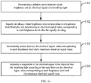
- FIG. 1a is a flowchart of a breathing light adjusting method according to an exemplary embodiment of the present invention.
- the executive entity of the breathing light adjusting method in this embodiment may be an electronic device provided with a breathing light, for example, a mobile or non-mobile electronic device such as a desktop, a laptop, a portable android device (PDA) or a mobile phone, and such electronic devices may be collectively referred to as "terminals".
- a software program is provided in the terminal to execute the breathing light adjusting method, or a logic circuit composed of various electronic components is provided in the terminal, and the breathing light adjusting method of this embodiment is implemented by the logic circuit.
- the breathing light adjusting method of this embodiment can specifically include: Step 101, determining a relation curve representing relationship between visual brightness and an electrical signal of a breathing light.
- the electrical signal driving the breathing light to emit light may be a current signal or a voltage signal, and in the following, the electrical signal being a current signal is taken as an example for illustration.
- the brightness of the breathing light increases with the increase of the driving current, and the breathing light brightness is approximately proportional to the driving current within a certain range (e.g. the range from Point o to Point A) of the driving current; the slope of the characteristic curve of the brightness the breathing light becomes smaller due to the increase of a temperature of the device when the current is outside of that range (extended from Point A to the range where the current increases). That is to say, the brightness of the breathing light does not strictly increase in proportion to the increase of the current intensity, and the brightness of the breathing light presents a nonlinear change with the change of the current.
- FIG. 1d is a relation curve representing relationship between the visual brightness and the electrical signal of the breathing light.
- Step 102 equally dividing a visual brightness interval according to a brightness level threshold, and determining an electrical signal value corresponding to each brightness level after the equally dividing.
- the brightness level threshold may be set by the user via the electronic device (in which a breathing light is integrated) thus to set the brightness level of the breathing light.
- the visual brightness is divided into levels according to the maximum visual brightness perceived by a human's eyes corresponding to the magnitude of the current of a constant current source.
- a visual brightness interval is equally divided, and a driving current value corresponding to each brightness level is obtained according to the relation curve of FIG. 1d .
- the driving current value is not distributed as being divided equally, but a brightness that changes level-by-level can be obtained through the gradual change of the driving current values.
- Step 103 determining a ratio between the electrical signal value corresponding to each brightness level and a maximum electrical signal value.
- the ratios between the electrical signal value corresponding to each brightness level, for example I 1 , I 2 ...I max in FIG. 1d , and I max is calculated, so that current ratio values corresponding to respective brightness levels, I 1 /I max , I 2 /I max ...1, are obtained.
- Step 104 adjusting a magnitude of an electrical signal value inputted into the breathing light according to the ratio between the electrical signal value corresponding to each brightness level and the maximum electrical signal value.
- the magnitude of the current value inputted into the breathing light is adjusted according to the ratio values of I 1 /I max , I 2 /I max ...1 corresponding to respective brightness levels obtained in Step 103.
- currents of I 1 , I 2 ...I max and I max are inputted into the breathing light, so that the breathing light presents an effect of gradual change from the first level of brightness to the eighth level of brightness; or currents of I max , I 7 , I 6 ...and I 1 may be inputted into the breathing light, so that the breathing light presents an effect of gradual change from the eighth level of brightness to the first level of brightness.
- the relation curve representing relationship between the visual brightness and the electrical signal of the breathing light is determined; the visual brightness interval is equally divided according to the brightness level threshold, and the electrical signal value corresponding to each brightness level after the equally dividing is determined; the ratio between the electrical signal value corresponding to each brightness level and the maximum electrical signal value is determined; and the magnitude of the electrical signal value inputted into the breathing light is adjusted according to the ratio between the electrical signal value corresponding to each brightness level and the maximum electrical signal value, so that the brightness of the breathing light presents an effect of linear gradual change which suits human vision.
- FIG. 2 is a flowchart of a breathing light adjusting method according to another exemplary embodiment of the present invention.
- the breathing light adjusting method of this embodiment specifically includes: Step 201, determining a relation curve representing relationship between actual amount of luminescence and the electrical signal of the breathing light; determining a relation curve representing relationship between the visual brightness and the actual amount of luminescence of the breathing light.
- the relation curve representing relationship between the actual amount of luminescence and the electrical signal of the breathing light is shown in FIG. 1b of the previous embodiment
- the relation curve representing relationship between the visual brightness and the actual amount of luminescence of the breathing light is shown in FIG. 1c of the previous embodiment.
- the above relation curves may be obtained by collecting a certain number of input current values of the breathing light and measuring brightness values corresponding to the respective collected current values, so that the above curves of FIG. 1b and FIG. 1c are obtained by fitting.
- Step 202 determining a relation curve representing relationship between the visual brightness and the electrical signal according to the relation curve representing relationship between the actual amount of luminescence and the electrical signal of the breathing light and the relation curve representing relationship between the visual brightness and the actual amount of luminescence of the breathing light.
- Step 203 equally dividing a visual brightness interval according to a brightness level threshold, and determining an electrical signal value corresponding to each brightness level after the equally dividing.
- Step 204 determining a ratio between the electrical signal value corresponding to each brightness level and a maximum electrical signal value.
- Step 205 generating a pulse width modulation (PWM) duty cycle control signal corresponding to each brightness level according to the ratio between the electrical signal value corresponding to each brightness level, the maximum electrical signal value and a period of a PWM signal.
- PWM pulse width modulation
- the Pulse Width Modulation is a technique of controlling an analog circuit by using a digital output of a microprocessor, in which PWM duty cycle control signals representing different current intensities are obtained by modulating the duty cycle of each PWM signal (a PWM signal period). Therefore, with the PWM signals with different duty cycles bearing different current intensities, the effect of the brightness of the breathing light gradually changing with the current intensity is achieved by sequentially inputting the PWM duty cycle control signal corresponding to each brightness level into the breathing light.
- Step 206 inputting the PWM duty cycle control signal corresponding to each brightness level into the breathing light sequentially, such that the breathing light presents a sequential change in brightness according to the brightness level.
- a first hold time of each brightness level may be determined according to a breathing cycle of the breathing light.
- the breathing cycle is a time interval between a display start time of the lowest brightness level and the display end time of the highest brightness level; or the breathing cycle is a time interval between the display start time of the highest brightness level and the display end time of the lowest brightness level.
- the breathing cycle of the breathing light may be equally divided according to the brightness level threshold to obtain the first hold time of each brightness level.
- the user may set a change trend of the brightness of the breathing light by himself/herself, where the change trend of the brightness level within each breathing cycle includes: sequentially changing from light to dark, or sequentially changing from dark to light; a change trend of the brightness between two adjacent breathing cycles includes at least one of the following changes: sequentially changing from dark to light, and then sequentially changing from light to dark; sequentially changing from light to dark, and then sequentially changing from dark to light; sequentially changing from light to dark, and then sequentially changing from light to dark; sequentially changing from dark to light, and then sequentially changing from dark to light.
- a second hold time may be set between every two breathing cycles, which is a time interval between adjacent breathing cycles.
- a hold time of a preset state between two adjacent breathing cycles is determined; where the preset state is a state in which the breathing light is completely off or a state in which the breathing light is maintained at any brightness level. That is to say, after the end of one breathing cycle, the breathing light stays completely off or in any preset brightness level for a certain time (the second hold time) and then enters the process of gradual change of the brightness in the next breathing cycle, where the second hold time and the preset state may be set by the user himself/herself.
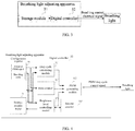
- FIG. 3 is a schematic structural diagram of a breathing light adjusting apparatus according to an exemplary embodiment of the present invention.
- the breathing light adjusting apparatus may be implemented by using a logic circuit, where the logic circuit includes the following logic modules: a storage module 31, configured to store ratio data, where the ratio data is ratio data between an electrical signal value corresponding to each brightness level and a maximum electrical signal value, where the electrical signal value corresponding to each brightness level is obtained by equally dividing a visual brightness interval according to a brightness level threshold based on a relation curve representing relationship between visual brightness and an electric signal of a breathing light, and determining the electrical signal value corresponding to each brightness level after the equally dividing; a digital controller 32, configured to read the ratio data from the storage module 31 and adjust a magnitude of the electrical signal value inputted into the breathing light according to the ratio data between the electrical signal value corresponding to each brightness level and the maximum electrical signal value.
- a storage module 31 configured to store ratio data, where the ratio data is ratio data between an electrical signal value corresponding to each brightness level and a maximum
- ratio data stored in the storage module 31 may be calculated by a processor integrated in the breathing light adjusting apparatus, and then the ratio data is stored in the storage module 31; or the ratio data may be calculated by an external electronic device independent of the breathing light adjusting apparatus, and the calculated ratio data may be transmitted to the breathing light adjusting apparatus by the external electronic device, and stored in the storage module 31.
- the breathing light adjusting apparatus of this embodiment may be used to perform the steps of the previous method embodiments.
- the implement principles thereof are similar, and will not be repeated herein.
- the breathing light adjusting apparatus of this embodiment includes a storage module which is configured to store ratio data; where the ratio data is the ratio data between the electrical signal value corresponding to each brightness level and the maximum electrical signal value, where the electrical signal value corresponding to each brightness level is obtained by equally dividing the visual brightness interval according to the brightness level threshold based on the relation curve representing relationship between visual brightness and the electric signal of the breathing light, and determining the electrical signal value corresponding to each brightness level after the equally dividing; the breathing light adjusting apparatus of this embodiment further includes a digital controller, which is configured to read the ratio data from the storage module and adjust the magnitude of the electrical signal value inputted into the breathing light according to the ratio data between the electrical signal value corresponding to each brightness level and the maximum electrical signal value, so that the brightness of the breathing light presents an effect of linear gradual change which suits human vision.
- FIG. 4 is a schematic structural diagram of a breathing light adjusting apparatus according to another exemplary embodiment of the present invention. As shown in FIG. 4 , on the basis of the above embodiment,
- the relation curve representing relationship between the visual brightness and the electrical signal of the breathing light is based on a relation curve representing relationship between actual amount of luminescence and the electrical signal of the breathing light; a relation curve representing relationship between the visual brightness and the actual amount of luminescence of the breathing light is determined; and the relation curve representing relationship between the visual brightness and the electrical signal of the breathing light is determined according to the relation curve representing relationship between the actual amount of luminescence and the electrical signal of the breathing light and the relation curve representing relationship between the visual brightness and the actual amount of luminescence of the breathing light.
- the storage module 31 may be a read only memory (ROM) in which the ratio data between the electrical signal value corresponding to each brightness level and the maximum electrical signal value is stored.
- ROM read only memory
- a relative current ratio of each level may be digitally encoded, for example, a 10-bit code is used to represent the relative current ratio of each level, and then each code is stored in the ROM.
- the breathing light adjusting apparatus further includes a configuration register 33, which stores a period of a Pulse Width Modulated (PWM) signal and may also store a breathing cycle of the breathing light.
- PWM Pulse Width Modulated
- the digital controller 32 includes: a duty cycle calculating module 321, configured to read the ratio data between the electrical signal value corresponding to each brightness level and the maximum electrical signal value from the ROM, read the period of the PWM signal from the configuration register 33, and generate a PWM duty cycle control signal corresponding to each brightness level according to the ratio data between the electrical signal value corresponding to each brightness level, the maximum electrical signal value and the period of the PWM signal.
- a duty cycle calculating module 321 configured to read the ratio data between the electrical signal value corresponding to each brightness level and the maximum electrical signal value from the ROM, read the period of the PWM signal from the configuration register 33, and generate a PWM duty cycle control signal corresponding to each brightness level according to the ratio data between the electrical signal value corresponding to each brightness level, the maximum electrical signal value and the period of the PWM signal.
- the duty cycle calculating module 321 multiplies the period value of the PWM signal read from the configuration register 33 by the 10-bit code corresponding to the current brightness level read from the ROM, and then extracts high bits of data according to a preset number of reserved bits to obtain the number of clock cycles in which a PWM output waveform is kept at high level (1). Where the number of clock cycles may be determined by counting through a first counter 324.
- the digital controller 32 further includes: the first counter 324, configured to count the clock cycle of the breathing light adjusting apparatus to obtain a value of the number of the clock cycle; and the first counter 324 is further configured to read the period of the PWM signal from the configuration register 33, compare the value of the number of the clock cycle with the period of the PWM signal, and clear the value of the number of the clock cycle at the end of each PWM signal period.
- the first counter 324 configured to count the clock cycle of the breathing light adjusting apparatus to obtain a value of the number of the clock cycle
- the first counter 324 is further configured to read the period of the PWM signal from the configuration register 33, compare the value of the number of the clock cycle with the period of the PWM signal, and clear the value of the number of the clock cycle at the end of each PWM signal period.
- the digital controller 32 further includes a brightness level controlling module 323.
- the brightness level controlling module 323 reads the breathing cycle from the configuration register 33 and determines a hold time of each brightness level according to the breathing cycle.
- a presentation time of brightness of each brightness level may be set to be the same.
- the brightness level controlling module 323 is configured to equally divide the breathing cycle of the breathing light according to the brightness level threshold to obtain a first hold time of each brightness level.
- the digital controller 32 further includes: a PWM generating module 322, configured to receive the PWM duty cycle control signal corresponding to each brightness level, input the PWM duty cycle control signal corresponding to each brightness level into the breathing light sequentially so as to enable the breathing light to present a sequential change in brightness according to the brightness level.
- a PWM generating module 322 configured to receive the PWM duty cycle control signal corresponding to each brightness level, input the PWM duty cycle control signal corresponding to each brightness level into the breathing light sequentially so as to enable the breathing light to present a sequential change in brightness according to the brightness level.
- the PWM generating module 322 is configured to receive the PWM duty cycle control signal corresponding to each brightness level outputted by the duty cycle calculating module 321, read the value of the number of the clock cycle from the first counter 324, compare the value of the number of the clock cycle with the PWM duty cycle control signal corresponding to each brightness level, determine whether each clock pulse signal in the PWM duty cycle control signal is set to 0 (low level) or 1 (high level), generate a clock pulse sequence of the PWM duty cycle control signal corresponding to each brightness level, then input the clock pulse sequence of the PWM duty cycle control signal corresponding to each brightness level into the breathing light sequentially, so as to enable the breathing light to present a sequential change in brightness according to the brightness level.
- the clock cycle of the breathing light adjusting apparatus is counted by a second counter 325 in the digital controller 32, to obtain the value of the number of the clock cycle; the second counter 325 is further configured to read the hold time of each brightness level from the brightness level controlling module 323, compare the value of the number of the clock cycle with the hold time of each brightness level, and clear the value of the number of the clock cycle at the end of the hold time of each brightness level.
- the brightness level controlling module 323 is further configured to progressively increase or decrease the current brightness level to an identifier corresponding to the next brightness level each time when the second counter clears the value of the number of the clock cycle (for example, increase or decrease the brightness level by 1 at the end of counting of each level), and send the identifier corresponding to the next brightness level to the ROM 33.
- the ROM 33 updates an addressing signal according to the identifier corresponding to the next brightness level, reads ratio data between an electrical signal value corresponding to the next brightness level and the maximum electrical signal value, so that the duty cycle calculating module 321 reads the data of each brightness level in the ROM to implement change among respective brightness levels.
- the PWM generating module 322 is further configured to determine a time for maintaining a preset state between two adjacent breathing cycles according to a second hold time, where the preset state is a state in which the breathing light is completely off, or a state in which the breathing light is maintained at any brightness level.
- the second hold time and the preset state may be set by the user himself/herself. Where timing the second hold time is initiated when the PWM generating module 322 has read that the current brightness level of the brightness level controlling module 323 is the last brightness level of the breathing cycle.
- the configuration register 33 further stores a change trend of the brightness level within each breathing cycle, where the change trend includes: sequentially changing from light to dark, or sequentially changing from dark to light.
- the configuration register 33 further stores the brightness change trend between two adjacent breathing cycles, and the change trend includes at least one of the following changes:
- the change trend may be set by the user himself/herself, so as to implement a more diverse effect of gradual change of the breathing light.
- the present invention also provides an electronic device including a program that enables the electronic device to perform the method of any of the previous embodiments when executed on the electronic device.
Landscapes
- Circuit Arrangement For Electric Light Sources In General (AREA)
- Engineering & Computer Science (AREA)
- Microelectronics & Electronic Packaging (AREA)
- General Engineering & Computer Science (AREA)
Abstract
Description
- The present invention relates to brightness adjustment technologies, in particular, to a breathing light adjusting method, an apparatus and an electronic device.
- A breathing light is a kind of signal light with even change of brightness, which can simulate the breathing effect of human being. Breathing lights are widely used in electronic products to serve as notifications and reminders.
- At present, a common method for implementing the breathing light is to generate a square wave with an evenly changing duty cycle as a driving control signal to drive an LED in the breathing light to emit light, by controlling a Pulse Width Modulation (PWM) module. However, in practical use, the evenly changing PWM duty cycle cannot result in an expected breathing effect, because brightness of the LED is not strictly proportional to a current intensity, that is to say, the brightness of the LED does not strictly increase in proportion to an increase of the current intensity, and the brightness of the LED does not strictly decrease in proportion to a decrease of the current intensity; at the same time, there is a nonlinear relationship between brightness perceived by a human's eyes and actual brightness of the LED. Therefore, when the PWM duty cycle of the driving control signal changes evenly, the brightness perceived by the human's eyes changes nonlinearly, which makes the effect of the evenly gradual change of the brightness of the breathing light undesirable.
- The present invention provides a breathing light adjustment method, an apparatus and an electronic device, which are used to solve the technical problem of the prior art that the effect of even gradual change of a breathing light brightness is not desirable.
- An aspect of the present invention provides a breathing light adjustment method, including:
- determining a relation curve representing relationship between visual brightness and an electrical signal of a breathing light;
- equally dividing a visual brightness interval according to a brightness level threshold, and determining an electrical signal value corresponding to each brightness level after the equally dividing;
- determining a ratio between the electrical signal value corresponding to each brightness level and a maximum electrical signal value; and
- adjusting, according to the ratio between the electrical signal value corresponding to each brightness level and the maximum electrical signal value, a magnitude of an electrical signal value inputted into the breathing light.
- Optionally, the determining a relation curve representing relationship between visual brightness and an electrical signal of a breathing light includes:
- determining a relation curve representing relationship between actual amount of luminescence and the electrical signal of the breathing light;
- determining a relation curve representing relationship between the visual brightness and the actual amount of luminescence of the breathing light; and
- determining the relation curve representing relationship between the visual brightness and the electrical signal according to the relation curve representing relationship between the actual amount of luminescence and the electrical signal of the breathing light and the relation curve representing relationship between the visual brightness and the actual amount of luminescence of the breathing light.
- Optionally, the adjusting, according to the ratio between the electrical signal value corresponding to each brightness level and the maximum electrical signal value, a magnitude of an electrical signal value inputted into the breathing light includes:
- generating a pulse width modulation (PWM) duty cycle control signal corresponding to each brightness level according to the ratio between the electrical signal value corresponding to each brightness level, the maximum electrical signal value and a period of a PWM signal; and
- inputting the PWM duty cycle control signal corresponding to each brightness level into the breathing light sequentially, such that the breathing light presents a sequential change in brightness according to the brightness level.
- Optionally, the method further includes:
determining a first hold time of each brightness level according to a breathing cycle of the breathing light. - Optionally, the determining a first hold time of each brightness level according to a breathing cycle of the breathing light includes:
equally dividing the breathing cycle of the breathing light according to the brightness level threshold to obtain the first hold time of each brightness level. - Optionally, the method further includes:
- a change trend of the brightness level within each breathing cycle includes: sequentially changing from light to dark, or sequentially changing from dark to light;
- a change trend of brightness between two adjacent breathing cycles includes at least one of the following changes:
- sequentially changing from dark to light, and then sequentially changing from light to dark;
- sequentially changing from light to dark, and then sequentially changing from dark to light;
- sequentially changing from light to dark, and then sequentially changing from light to dark;
- sequentially changing from dark to light, and then sequentially changing from dark to light.
- Optionally, the method further includes:
determining, according to a second hold time, a time for maintaining a preset state between two adjacent breathing cycles; where the preset state is a state in which the breathing light is completely off, or a state in which the breathing light is maintained at any of the brightness level. - Another aspect of the present invention provides a breathing light adjusting apparatus, including:
- a storage module, configured to store ratio data, where the ratio data is ratio data between an electrical signal value corresponding to each brightness level and a maximum electrical signal value, where the electrical signal value corresponding to each brightness level is obtained by equally dividing a visual brightness interval according to a brightness level threshold based on a relation curve representing relationship between visual brightness and an electric signal of a breathing light, and determining the electrical signal value corresponding to each brightness level after the equally dividing; and
- further including: a digital controller, configured to read the ratio data from the storage module, and adjust, according to the ratio data between the electrical signal value corresponding to each brightness level and the maximum electrical signal value, a magnitude of the electrical signal value inputted into the breathing light.
- Optionally, the relation curve representing relationship between the visual brightness and the electrical signal of the breathing light is determined as follows: determining a relation curve representing relationship between actual amount of luminescence and the electrical signal of the breathing light; determining a relation curve representing relationship between visual brightness and the actual amount of luminescence of the breathing light; and determining the relation curve representing relationship between the visual brightness and the electrical signal of the breathing light according to a relation curve representing relationship between the actual amount of luminescence and the electrical signal of the breathing light and a relation curve representing relationship between the visual brightness and the actual amount of luminescence of the breathing light.
- Optionally, further including: a configuration register; where the configuration register stores a period of a Pulse Width Modulation (PWM) signal; the storage module is a read only memory (ROM), and the ROM stores the ratio data between the electrical signal value corresponding to each brightness level and the maximum electrical signal value; the digital controller includes: a duty cycle calculating module, configured to read the ratio data between the electrical signal value corresponding to each brightness level and the maximum electrical signal value from the ROM, read the period of the PWM signal from the configuration register, and generate a PWM duty cycle control signal corresponding to each brightness level according to the ratio data between the electrical signal value corresponding to each brightness level, the maximum electrical signal value and the period of the PWM signal;
- further including: a PWM generating module, configured to receive the PWM duty cycle control signal corresponding to each brightness level, and sequentially input the PWM duty cycle control signal corresponding to each brightness level into the breathing light, such that the breathing light presents a sequential change in brightness according to the brightness level.
- Optionally, the configuration register further stores a breathing cycle of the breathing light, and the digital controller further includes a brightness level controlling module;
where the brightness level controlling module is configured to read the breathing cycle from the configuration register and determine a hold time of each brightness level according to the breathing cycle of the breathing light. - Optionally, the brightness level controlling module is specifically configured to equally divide the breathing cycle of the breathing light according to the brightness level threshold to obtain a first hold time of each brightness level.
- Optionally, further including: a first counter;
where the first counter is configured to count a clock cycle of the breathing light adjusting apparatus to obtain a value of the number of the clock cycle, and the first counter is further configured to read the period of the PWM signal from the configuration register, compare the value of the number of the clock cycle with the period of the PWM signal, and clear the value of the number of the clock cycle at the end of each period of the PWM signal. - Optionally, the PWM generating module is specifically configured to receive the PWM duty cycle control signal corresponding to each brightness level, read the value of the number of the clock cycle counted by the first counter, compare the value of the number of the clock cycle with the PWM duty cycle control signal corresponding to each brightness level, determine whether each clock pulse signal in the PWM duty cycle control signal is set to 0 or 1, generate a clock pulse sequence of the PWM duty cycle control signal corresponding to each brightness level, and sequentially input the clock pulse sequence of the PWM duty cycle control signal corresponding to each brightness level into the breathing light, such that the breathing light presents a sequential change in brightness according to the brightness level.
- Optionally, further including: a second counter;
where the second counter is configured to count a clock cycle of the breathing light adjusting apparatus to obtain a value of the number of the clock cycle, and the second counter is further configured to read the hold time of each brightness level from the brightness level controlling module, compare the value of the number of the clock cycle with the hold time of each brightness level, and clear the value of the number of the clock cycle at the end of the hold time of each brightness level. - Optionally, the brightness level controlling module is further configured to progressively increase or decrease a current brightness level to an identifier corresponding to a next brightness level each time when the second counter clears the value of the number of the clock cycle, and send the identifier corresponding to the next brightness level to the ROM;
the ROM updates an addressing signal according to the identifier corresponding to the next brightness level, and reads ratio data between an electrical signal value corresponding to the next brightness level indicated by the identifier and the maximum electrical signal value. - Optionally, the PWM generating module is further configured to determine, according to a second hold time, a time for maintaining a preset state between two adjacent breathing cycles; where the preset state is a state in which the breathing light is completely off, or a state in which the breathing light is maintained at any of the brightness level.
- Optionally, the PWM generating module is specifically configured to read the current brightness level of the brightness level controlling module, and initiate timing the second hold time when the current brightness level is a last brightness level of the breathing cycle.
- Optionally, the configuration register further stores a change trend of the brightness level within each breathing cycle, and the change trend of the brightness level within each breathing cycle includes: sequentially changing from light to dark, or sequentially changing from dark to light;
the configuration register further stores a change trend of brightness between two adjacent breathing cycles, and the brightness change trend between the two adjacent breathing cycles includes at least one of the following changes:
sequentially changing from dark to light, and then sequentially changing from light to dark;
sequentially changing from light to dark, and then sequentially changing from dark to light;
sequentially changing from light to dark, and then sequentially changing from light to dark;
sequentially changing from dark to light and then sequentially changing from dark to light. - Yet another aspect of the present invention provides an electronic device, including a program that enables the electronic device to perform the method according to any one of the methods described above when executed on the electronic device.
- As can be seen from the above aspects, in the breathing light adjustment method, apparatus and electronic device of the present invention, the relation curve representing relationship between the visual brightness and the electrical signal of the breathing light is determined; the visual brightness interval is equally divided according to the brightness level threshold, and the electrical signal value corresponding to each brightness level after the equally dividing is determined; the ratio between the electrical signal value corresponding to each brightness level and the maximum electrical signal value is determined; and the magnitude of the electrical signal value inputted into the breathing light is adjusted according to the ratio between the electrical signal value corresponding to each brightness level and the maximum electrical signal value, so that the brightness of the breathing light presents an effect of linear gradual change which suits human vision.
- In order to more clearly illustrate technical solutions in embodiments of the present invention or in the prior art, accompanying drawings required for describing the embodiments or the prior art will be briefly described below. Apparently, the accompanying drawings in the following description are some of the embodiments of the present invention, and other drawings can be obtained by those skilled in the art based on these accompanying drawings without any creative effort.
-
FIG. 1a is a flowchart of a breathing light adjusting method according to an exemplary embodiment of the present invention; -
FIG. 1b is a graph of a relation curve representing relationship between actual brightness and a current according to the embodiment illustrated inFIG. 1a ; -
FIG. 1c is a graph of a relation curve representing relationship between actual brightness and visual brightness according to the embodiment illustrated inFIG. 1a ; -
FIG. 1d is a graph of a relation curve representing relationship between visual brightness and a current according to the embodiment illustrated inFIG. 1a ; -
FIG. 2 is a flowchart of a breathing light adjusting method according to another exemplary embodiment of the present invention; -
FIG. 3 is a schematic structural diagram of a breathing light adjusting apparatus according to an exemplary embodiment of the present invention; and -
FIG. 4 is a schematic structural diagram of a breathing light adjusting apparatus according to another exemplary embodiment of the present invention. - Technical solutions in embodiments of the present invention will be clearly and completely described below in conjunction with the accompanying drawings in the embodiments of the present invention, in order to make the objects, technical solutions and advantages of the embodiments of the present invention clearer. Apparently, the described embodiments are a part of, instead of all of the embodiments of the present invention. All other embodiments obtained by those skilled in the art based on the embodiments of the present invention without creative labor will fall within the scope of the present invention.
-
FIG. 1a is a flowchart of a breathing light adjusting method according to an exemplary embodiment of the present invention. As shown inFIG. 1a , the executive entity of the breathing light adjusting method in this embodiment may be an electronic device provided with a breathing light, for example, a mobile or non-mobile electronic device such as a desktop, a laptop, a portable android device (PDA) or a mobile phone, and such electronic devices may be collectively referred to as "terminals". A software program is provided in the terminal to execute the breathing light adjusting method, or a logic circuit composed of various electronic components is provided in the terminal, and the breathing light adjusting method of this embodiment is implemented by the logic circuit. The breathing light adjusting method of this embodiment can specifically include:
Step 101, determining a relation curve representing relationship between visual brightness and an electrical signal of a breathing light. - In this step, the electrical signal driving the breathing light to emit light may be a current signal or a voltage signal, and in the following, the electrical signal being a current signal is taken as an example for illustration. As shown in
FIG. 1b , the brightness of the breathing light increases with the increase of the driving current, and the breathing light brightness is approximately proportional to the driving current within a certain range (e.g. the range from Point o to Point A) of the driving current; the slope of the characteristic curve of the brightness the breathing light becomes smaller due to the increase of a temperature of the device when the current is outside of that range (extended from Point A to the range where the current increases). That is to say, the brightness of the breathing light does not strictly increase in proportion to the increase of the current intensity, and the brightness of the breathing light presents a nonlinear change with the change of the current. - At the same time, according to the Weber-Fechner Law, the brightness perceived by a human's eyes is logarithmic to the actual brightness, as shown in
FIG. 1c . Therefore, according toFIG. 1b and FIG. 1c , a relation curve representing relationship between the current and the visual brightness perceived by a human's eyes can be obtained (as shown inFIG. 1d). FIG. 1d is a relation curve representing relationship between the visual brightness and the electrical signal of the breathing light. -
Step 102, equally dividing a visual brightness interval according to a brightness level threshold, and determining an electrical signal value corresponding to each brightness level after the equally dividing. - In this step, the brightness level threshold may be set by the user via the electronic device (in which a breathing light is integrated) thus to set the brightness level of the breathing light. The greater the brightness level threshold is, the more brightness levels of the brightness gradual change the breathing light presents, and the more desirable the effect of gradual change is; the smaller the brightness level threshold is, the less brightness levels of the brightness gradual change the breathing light presents, and if there are too few brightness levels, the change of the brightness of the breathing light will be unsmooth in the view of a person. Therefore, preferably, the brightness level threshold may be set to 128 levels of brightness, and for the purpose of simplicity for illustration,
FIG. 1d shows the effect when the brightness level threshold is 8 levels. The visual brightness is divided into levels according to the maximum visual brightness perceived by a human's eyes corresponding to the magnitude of the current of a constant current source. In order to present a linear change in brightness, a visual brightness interval is equally divided, and a driving current value corresponding to each brightness level is obtained according to the relation curve ofFIG. 1d . The driving current value is not distributed as being divided equally, but a brightness that changes level-by-level can be obtained through the gradual change of the driving current values. -
Step 103, determining a ratio between the electrical signal value corresponding to each brightness level and a maximum electrical signal value. - In this step, the ratios between the electrical signal value corresponding to each brightness level, for example I1, I2...Imax in
FIG. 1d , and Imax is calculated, so that current ratio values corresponding to respective brightness levels, I1/Imax, I2/Imax...1, are obtained. - Step 104, adjusting a magnitude of an electrical signal value inputted into the breathing light according to the ratio between the electrical signal value corresponding to each brightness level and the maximum electrical signal value.
- In this step, the magnitude of the current value inputted into the breathing light is adjusted according to the ratio values of I1/Imax, I2/Imax...1 corresponding to respective brightness levels obtained in
Step 103. For example, currents of I1, I2...Imax and Imax are inputted into the breathing light, so that the breathing light presents an effect of gradual change from the first level of brightness to the eighth level of brightness; or currents of Imax, I7, I6...and I1 may be inputted into the breathing light, so that the breathing light presents an effect of gradual change from the eighth level of brightness to the first level of brightness. - In the breathing light adjusting method of this embodiment, the relation curve representing relationship between the visual brightness and the electrical signal of the breathing light is determined; the visual brightness interval is equally divided according to the brightness level threshold, and the electrical signal value corresponding to each brightness level after the equally dividing is determined; the ratio between the electrical signal value corresponding to each brightness level and the maximum electrical signal value is determined; and the magnitude of the electrical signal value inputted into the breathing light is adjusted according to the ratio between the electrical signal value corresponding to each brightness level and the maximum electrical signal value, so that the brightness of the breathing light presents an effect of linear gradual change which suits human vision.
-
FIG. 2 is a flowchart of a breathing light adjusting method according to another exemplary embodiment of the present invention. As shown inFIG. 2 , based on the previous embodiment, the breathing light adjusting method of this embodiment specifically includes:
Step 201, determining a relation curve representing relationship between actual amount of luminescence and the electrical signal of the breathing light; determining a relation curve representing relationship between the visual brightness and the actual amount of luminescence of the breathing light. - In this step, the relation curve representing relationship between the actual amount of luminescence and the electrical signal of the breathing light is shown in
FIG. 1b of the previous embodiment, and the relation curve representing relationship between the visual brightness and the actual amount of luminescence of the breathing light is shown inFIG. 1c of the previous embodiment. The above relation curves may be obtained by collecting a certain number of input current values of the breathing light and measuring brightness values corresponding to the respective collected current values, so that the above curves ofFIG. 1b and FIG. 1c are obtained by fitting. -
Step 202, determining a relation curve representing relationship between the visual brightness and the electrical signal according to the relation curve representing relationship between the actual amount of luminescence and the electrical signal of the breathing light and the relation curve representing relationship between the visual brightness and the actual amount of luminescence of the breathing light. -
Step 203, equally dividing a visual brightness interval according to a brightness level threshold, and determining an electrical signal value corresponding to each brightness level after the equally dividing. -
Step 204, determining a ratio between the electrical signal value corresponding to each brightness level and a maximum electrical signal value. -
Step 205, generating a pulse width modulation (PWM) duty cycle control signal corresponding to each brightness level according to the ratio between the electrical signal value corresponding to each brightness level, the maximum electrical signal value and a period of a PWM signal. - In this step, the Pulse Width Modulation is a technique of controlling an analog circuit by using a digital output of a microprocessor, in which PWM duty cycle control signals representing different current intensities are obtained by modulating the duty cycle of each PWM signal (a PWM signal period). Therefore, with the PWM signals with different duty cycles bearing different current intensities, the effect of the brightness of the breathing light gradually changing with the current intensity is achieved by sequentially inputting the PWM duty cycle control signal corresponding to each brightness level into the breathing light.
-
Step 206, inputting the PWM duty cycle control signal corresponding to each brightness level into the breathing light sequentially, such that the breathing light presents a sequential change in brightness according to the brightness level. - In this step, in order to control a gradual change time of the breathing light, a first hold time of each brightness level may be determined according to a breathing cycle of the breathing light. Where the breathing cycle is a time interval between a display start time of the lowest brightness level and the display end time of the highest brightness level; or the breathing cycle is a time interval between the display start time of the highest brightness level and the display end time of the lowest brightness level.
- Optionally, in order to make the effect of the gradual change of the breathing light more even, that is to say, to make the breathing light stay at each brightness level for an equal period of time, the breathing cycle of the breathing light may be equally divided according to the brightness level threshold to obtain the first hold time of each brightness level.
- Optionally, in order to make the effect of the gradual change of the breathing light more diverse, the user may set a change trend of the brightness of the breathing light by himself/herself, where the change trend of the brightness level within each breathing cycle includes: sequentially changing from light to dark, or sequentially changing from dark to light; a change trend of the brightness between two adjacent breathing cycles includes at least one of the following changes: sequentially changing from dark to light, and then sequentially changing from light to dark; sequentially changing from light to dark, and then sequentially changing from dark to light; sequentially changing from light to dark, and then sequentially changing from light to dark; sequentially changing from dark to light, and then sequentially changing from dark to light.
- Optionally, a second hold time may be set between every two breathing cycles, which is a time interval between adjacent breathing cycles. According to the second hold time, a hold time of a preset state between two adjacent breathing cycles is determined; where the preset state is a state in which the breathing light is completely off or a state in which the breathing light is maintained at any brightness level. That is to say, after the end of one breathing cycle, the breathing light stays completely off or in any preset brightness level for a certain time (the second hold time) and then enters the process of gradual change of the brightness in the next breathing cycle, where the second hold time and the preset state may be set by the user himself/herself.
-
FIG. 3 is a schematic structural diagram of a breathing light adjusting apparatus according to an exemplary embodiment of the present invention. As shown inFIG. 3 , the breathing light adjusting apparatus may be implemented by using a logic circuit, where the logic circuit includes the following logic modules:
astorage module 31, configured to store ratio data, where the ratio data is ratio data between an electrical signal value corresponding to each brightness level and a maximum electrical signal value, where the electrical signal value corresponding to each brightness level is obtained by equally dividing a visual brightness interval according to a brightness level threshold based on a relation curve representing relationship between visual brightness and an electric signal of a breathing light, and determining the electrical signal value corresponding to each brightness level after the equally dividing; adigital controller 32, configured to read the ratio data from thestorage module 31 and adjust a magnitude of the electrical signal value inputted into the breathing light according to the ratio data between the electrical signal value corresponding to each brightness level and the maximum electrical signal value. - Where the ratio data stored in the
storage module 31 may be calculated by a processor integrated in the breathing light adjusting apparatus, and then the ratio data is stored in thestorage module 31; or the ratio data may be calculated by an external electronic device independent of the breathing light adjusting apparatus, and the calculated ratio data may be transmitted to the breathing light adjusting apparatus by the external electronic device, and stored in thestorage module 31. - The breathing light adjusting apparatus of this embodiment may be used to perform the steps of the previous method embodiments. The implement principles thereof are similar, and will not be repeated herein.
- The breathing light adjusting apparatus of this embodiment includes a storage module which is configured to store ratio data; where the ratio data is the ratio data between the electrical signal value corresponding to each brightness level and the maximum electrical signal value, where the electrical signal value corresponding to each brightness level is obtained by equally dividing the visual brightness interval according to the brightness level threshold based on the relation curve representing relationship between visual brightness and the electric signal of the breathing light, and determining the electrical signal value corresponding to each brightness level after the equally dividing; the breathing light adjusting apparatus of this embodiment further includes a digital controller, which is configured to read the ratio data from the storage module and adjust the magnitude of the electrical signal value inputted into the breathing light according to the ratio data between the electrical signal value corresponding to each brightness level and the maximum electrical signal value, so that the brightness of the breathing light presents an effect of linear gradual change which suits human vision.
-
FIG. 4 is a schematic structural diagram of a breathing light adjusting apparatus according to another exemplary embodiment of the present invention. As shown inFIG. 4 , on the basis of the above embodiment, - the relation curve representing relationship between the visual brightness and the electrical signal of the breathing light is based on a relation curve representing relationship between actual amount of luminescence and the electrical signal of the breathing light; a relation curve representing relationship between the visual brightness and the actual amount of luminescence of the breathing light is determined; and the relation curve representing relationship between the visual brightness and the electrical signal of the breathing light is determined according to the relation curve representing relationship between the actual amount of luminescence and the electrical signal of the breathing light and the relation curve representing relationship between the visual brightness and the actual amount of luminescence of the breathing light.
- Optionally, the
storage module 31 may be a read only memory (ROM) in which the ratio data between the electrical signal value corresponding to each brightness level and the maximum electrical signal value is stored. Specifically, a relative current ratio of each level may be digitally encoded, for example, a 10-bit code is used to represent the relative current ratio of each level, and then each code is stored in the ROM. - Optionally, the breathing light adjusting apparatus further includes a
configuration register 33, which stores a period of a Pulse Width Modulated (PWM) signal and may also store a breathing cycle of the breathing light. - The
digital controller 32 includes: a dutycycle calculating module 321, configured to read the ratio data between the electrical signal value corresponding to each brightness level and the maximum electrical signal value from the ROM, read the period of the PWM signal from theconfiguration register 33, and generate a PWM duty cycle control signal corresponding to each brightness level according to the ratio data between the electrical signal value corresponding to each brightness level, the maximum electrical signal value and the period of the PWM signal. - Specifically, the duty
cycle calculating module 321 multiplies the period value of the PWM signal read from theconfiguration register 33 by the 10-bit code corresponding to the current brightness level read from the ROM, and then extracts high bits of data according to a preset number of reserved bits to obtain the number of clock cycles in which a PWM output waveform is kept at high level (1). Where the number of clock cycles may be determined by counting through afirst counter 324. - Optionally, the
digital controller 32 further includes: thefirst counter 324, configured to count the clock cycle of the breathing light adjusting apparatus to obtain a value of the number of the clock cycle; and thefirst counter 324 is further configured to read the period of the PWM signal from theconfiguration register 33, compare the value of the number of the clock cycle with the period of the PWM signal, and clear the value of the number of the clock cycle at the end of each PWM signal period. - Optionally, the
digital controller 32 further includes a brightnesslevel controlling module 323. The brightnesslevel controlling module 323 reads the breathing cycle from theconfiguration register 33 and determines a hold time of each brightness level according to the breathing cycle. - In order to enable the breathing light to present an effect of even change in time of gradually changing brightness, a presentation time of brightness of each brightness level may be set to be the same. Specifically, the brightness
level controlling module 323 is configured to equally divide the breathing cycle of the breathing light according to the brightness level threshold to obtain a first hold time of each brightness level. - Optionally, the
digital controller 32 further includes: aPWM generating module 322, configured to receive the PWM duty cycle control signal corresponding to each brightness level, input the PWM duty cycle control signal corresponding to each brightness level into the breathing light sequentially so as to enable the breathing light to present a sequential change in brightness according to the brightness level. - Specifically, the
PWM generating module 322 is configured to receive the PWM duty cycle control signal corresponding to each brightness level outputted by the dutycycle calculating module 321, read the value of the number of the clock cycle from thefirst counter 324, compare the value of the number of the clock cycle with the PWM duty cycle control signal corresponding to each brightness level, determine whether each clock pulse signal in the PWM duty cycle control signal is set to 0 (low level) or 1 (high level), generate a clock pulse sequence of the PWM duty cycle control signal corresponding to each brightness level, then input the clock pulse sequence of the PWM duty cycle control signal corresponding to each brightness level into the breathing light sequentially, so as to enable the breathing light to present a sequential change in brightness according to the brightness level. - In addition, in order to implement an effect of level-by-level change in various brightness levels, the clock cycle of the breathing light adjusting apparatus is counted by a
second counter 325 in thedigital controller 32, to obtain the value of the number of the clock cycle; thesecond counter 325 is further configured to read the hold time of each brightness level from the brightnesslevel controlling module 323, compare the value of the number of the clock cycle with the hold time of each brightness level, and clear the value of the number of the clock cycle at the end of the hold time of each brightness level. - Correspondingly, the brightness
level controlling module 323 is further configured to progressively increase or decrease the current brightness level to an identifier corresponding to the next brightness level each time when the second counter clears the value of the number of the clock cycle (for example, increase or decrease the brightness level by 1 at the end of counting of each level), and send the identifier corresponding to the next brightness level to theROM 33. TheROM 33 updates an addressing signal according to the identifier corresponding to the next brightness level, reads ratio data between an electrical signal value corresponding to the next brightness level and the maximum electrical signal value, so that the dutycycle calculating module 321 reads the data of each brightness level in the ROM to implement change among respective brightness levels. - Optionally, the
PWM generating module 322 is further configured to determine a time for maintaining a preset state between two adjacent breathing cycles according to a second hold time, where the preset state is a state in which the breathing light is completely off, or a state in which the breathing light is maintained at any brightness level. As mentioned above, the second hold time and the preset state may be set by the user himself/herself. Where timing the second hold time is initiated when thePWM generating module 322 has read that the current brightness level of the brightnesslevel controlling module 323 is the last brightness level of the breathing cycle. - Optionally, the
configuration register 33 further stores a change trend of the brightness level within each breathing cycle, where the change trend includes: sequentially changing from light to dark, or sequentially changing from dark to light. Theconfiguration register 33 further stores the brightness change trend between two adjacent breathing cycles, and the change trend includes at least one of the following changes: - sequentially changing from dark to light, and then sequentially changing from light to dark;
- sequentially changing from light to dark, and then sequentially changing from dark to light;
- sequentially changing from light to dark, and then sequentially changing from light to dark;
- sequentially changing from dark to light, and then sequentially changing from dark to light.
- As mentioned above, the change trend may be set by the user himself/herself, so as to implement a more diverse effect of gradual change of the breathing light.
- The present invention also provides an electronic device including a program that enables the electronic device to perform the method of any of the previous embodiments when executed on the electronic device.
- It should be noted that the above embodiments are only used to illustrate the technical solutions of the present invention, and the technical solutions of the present invention are not limited thereto. Although the present invention has been described in detail with reference to the foregoing embodiments, those skilled in the art should understand that the technical solutions described in the above embodiments may be modified, or some of the technical features may be equivalently substituted, and those modifications or substitutions do not deviate the nature of the corresponding technical solutions from the scope of the technical solutions of respective embodiments of the present invention.
Claims (20)
- A breathing light adjusting method, comprising:determining a relation curve representing relationship between visual brightness and an electrical signal of a breathing light;equally dividing a visual brightness interval according to a brightness level threshold, and determining an electrical signal value corresponding to each brightness level after the equally dividing;determining a ratio between the electrical signal value corresponding to each brightness level and a maximum electrical signal value; andadjusting, according to the ratio between the electrical signal value corresponding to each brightness level and the maximum electrical signal value, a magnitude of an electrical signal value inputted into the breathing light.
- The method according to claim 1, wherein the determining a relation curve representing relationship between visual brightness and an electrical signal of a breathing light comprises:determining a relation curve representing relationship between actual amount of luminescence and the electrical signal of the breathing light;determining a relation curve representing relationship between the visual brightness and the actual amount of luminescence of the breathing light; anddetermining the relation curve representing relationship between the visual brightness and the electrical signal, according to the relation curve representing relationship between the actual amount of luminescence and the electrical signal of the breathing light and, the relation curve representing relationship between the visual brightness and the actual amount of luminescence of the breathing light.
- The method according to claim 1, wherein the adjusting, according to the ratio between the electrical signal value corresponding to each brightness level and the maximum electrical signal value, a magnitude of an electrical signal value inputted into the breathing light comprises:generating, according to the ratio between the electrical signal value corresponding to each brightness level, the maximum electrical signal value and a period of a PWM signal, a pulse width modulation (PWM) duty cycle control signal corresponding to each brightness level; andinputting the PWM duty cycle control signal corresponding to each brightness level into the breathing light sequentially, such that the breathing light presents a sequential change in brightness according to the brightness level.
- The method according to claim 1, wherein the method further comprises:
determining a first hold time of each brightness level according to a breathing cycle of the breathing light. - The method according to claim 4, wherein the determining a first hold time of each brightness level according to a breathing cycle of the breathing light comprises:
equally dividing the breathing cycle of the breathing light according to the brightness level threshold to obtain the first hold time of each brightness level. - The method according to claim 4, wherein the method further comprises:a change trend of the brightness level within each breathing cycle comprises: sequentially changing from light to dark, or sequentially changing from dark to light;a change trend of brightness between two adjacent breathing cycles comprises at least one of the following changes:sequentially changing from dark to light, and then sequentially changing from light to dark;sequentially changing from light to dark, and then sequentially changing from dark to light;sequentially changing from light to dark, and then sequentially changing from light to dark;sequentially changing from dark to light, and then sequentially changing from dark to light.
- The method according to claim 4, wherein the method further comprises:
determining, according to a second hold time, a time for maintaining a preset state between two adjacent breathing cycles; wherein the preset state is a state the breathing light is completely off, or a state the breathing light is maintained at any of the brightness level. - A breathing light adjusting apparatus, comprising:a storage module, configured to store ratio data, wherein the ratio data is ratio data between an electrical signal value corresponding to each brightness level and a maximum electrical signal value, wherein the electrical signal value corresponding to each brightness level is obtained by equally dividing a visual brightness interval according to a brightness level threshold based on a relation curve representing relationship between visual brightness and an electric signal of a breathing light, and determining the electrical signal value corresponding to each brightness level after the equally dividing; andfurther comprising: a digital controller, configured to read the ratio data from the storage module, and adjust, according to the ratio data between the electrical signal value corresponding to each brightness level and the maximum electrical signal value, a magnitude of the electrical signal value inputted into the breathing light.
- The apparatus according to claim 8, wherein the relation curve representing relationship between the visual brightness and the electrical signal of the breathing light is determined by:determining a relation curve representing relationship between actual amount of luminescence and the electrical signal of the breathing light;determining a relation curve representing relationship between visual brightness and the actual amount of luminescence of the breathing light; anddetermining the relation curve representing relationship between the visual brightness and the electrical signal of the breathing light according to the relation curve representing relationship between the actual amount of luminescence and the electrical signal of the breathing light and the relation curve representing relationship between the visual brightness and the actual amount of luminescence of the breathing light.
- The apparatus according to claim 8, further comprising: a configuration register; wherein the configuration register stores a period of a Pulse Width Modulation (PWM) signal; the storage module is a read only memory (ROM), and the ROM stores the ratio data between the electrical signal value corresponding to each brightness level and the maximum electrical signal value; the digital controller comprises: a duty cycle calculating module, configured to read the ratio data between the electrical signal value corresponding to each brightness level and the maximum electrical signal value from the ROM, read the period of the PWM signal from the configuration register, and generate a PWM duty cycle control signal corresponding to each brightness level according to the ratio data between the electrical signal value corresponding to each brightness level, the maximum electrical signal value and the period of the PWM signal;
further comprising: a PWM generating module, configured to receive the PWM duty cycle control signal corresponding to each brightness level, and sequentially input the PWM duty cycle control signal corresponding to each brightness level into the breathing light, such that the breathing light presents a sequential change in brightness according to the brightness level. - The apparatus according to claim 10, wherein the configuration register further stores a breathing cycle of the breathing light, and the digital controller further comprises a brightness level controlling module;
wherein the brightness level controlling module is configured to read the breathing cycle from the configuration register and determine a hold time of each brightness level according to the breathing cycle of the breathing light. - The apparatus according to claim 11, wherein,
the brightness level controlling module is specifically configured to equally divide the breathing cycle of the breathing light according to the brightness level threshold to obtain a first hold time of each brightness level. - The apparatus according to claim 12, further comprising: a first counter;
wherein the first counter is configured to count a clock cycle of the breathing light adjusting apparatus to obtain a value of the number of the clock cycle, and the first counter is further configured to read the period of the PWM signal from the configuration register, compare the value of the number of the clock cycle with the period of the PWM signal, and clear the value of the number of the clock cycle at the end of each period of the PWM signal. - The apparatus according to claim 13, wherein,
the PWM generating module is specifically configured to receive the PWM duty cycle control signal corresponding to each brightness level, read the value of the number of the clock cycle counted by the first counter, compare the value of the number of the clock cycle with the PWM duty cycle control signal corresponding to each brightness level, determine whether each clock pulse signal in the PWM duty cycle control signal is set to 0 or 1, generate a clock pulse sequence of the PWM duty cycle control signal corresponding to each brightness level, and sequentially input the clock pulse sequence of the PWM duty cycle control signal corresponding to each brightness level into the breathing light, such that the breathing light presents a sequential change in brightness according to the brightness level. - The apparatus according to claim 12, further comprising: a second counter;
wherein the second counter is configured to count a clock cycle of the breathing light adjusting apparatus to obtain a value of the number of the clock cycle, and the second counter is further configured to read the hold time of each brightness level from the brightness level controlling module, compare the value of the number of the clock cycle with the hold time of each brightness level, and clear the value of the number of the clock cycle at the end of the hold time of each brightness level. - The apparatus according to claim 15, wherein,
the brightness level controlling module is further configured to progressively increase or decrease a current brightness level to an identifier corresponding to a next brightness level each time when the second counter clears the value of the number of the clock cycle, and send the identifier corresponding to the next brightness level to the ROM;
the ROM updates an addressing signal according to the identifier corresponding to the next brightness level, and reads ratio data between an electrical signal value corresponding to the next brightness level indicated by the identifier and the maximum electrical signal value. - The apparatus according to claim 16, wherein,
the PWM generating module is further configured to determine, according to a second hold time, a time for maintaining a preset state between two adjacent breathing cycles; wherein the preset state is a state the breathing light is completely off, or a state the breathing light is maintained at any of the brightness level. - The apparatus according to claim 17, wherein,
the PWM generating module is specifically configured to read the current brightness level of the brightness level controlling module, and initiate timing the second hold time when the current brightness level is a last brightness level of the breathing cycle. - The apparatus according to claim 11, wherein,
the configuration register further stores a change trend of the brightness level within each breathing cycle, and the change trend of the brightness level within each breathing cycle comprises: sequentially changing from light to dark, or sequentially changing from dark to light;
the configuration register further stores a change trend of brightness between two adjacent breathing cycles, and the brightness change trend between the two adjacent breathing cycles comprises at least one of the following changes:sequentially changing from dark to light, and then sequentially changing from light to dark;sequentially changing from light to dark, and then sequentially changing from dark to light;sequentially changing from light to dark, and then sequentially changing from light to dark;sequentially changing from dark to light and then sequentially changing from dark to light. - An electronic device, comprising: a program that enables the electronic device to perform the method according to any one of claims 1-7 when executed on the electronic device.
Applications Claiming Priority (1)
| Application Number | Priority Date | Filing Date | Title |
|---|---|---|---|
| PCT/CN2018/078293 WO2019169579A1 (en) | 2018-03-07 | 2018-03-07 | Breathing lamp adjustment method and apparatus, and electronic device |
Publications (3)
| Publication Number | Publication Date |
|---|---|
| EP3565384A1 true EP3565384A1 (en) | 2019-11-06 |
| EP3565384A4 EP3565384A4 (en) | 2020-02-26 |
| EP3565384B1 EP3565384B1 (en) | 2021-09-29 |
Family
ID=67846425
Family Applications (1)
| Application Number | Title | Priority Date | Filing Date |
|---|---|---|---|
| EP18893337.8A Not-in-force EP3565384B1 (en) | 2018-03-07 | 2018-03-07 | Notification lamp adjustment method and apparatus, and electronic device |
Country Status (4)
| Country | Link |
|---|---|
| US (1) | US11184962B2 (en) |
| EP (1) | EP3565384B1 (en) |
| CN (1) | CN110622621A (en) |
| WO (1) | WO2019169579A1 (en) |
Families Citing this family (11)
| Publication number | Priority date | Publication date | Assignee | Title |
|---|---|---|---|---|
| US11462192B2 (en) * | 2020-05-18 | 2022-10-04 | Rockwell Collins, Inc. | Flipped or frozen display monitor |
| CN111954334B (en) * | 2020-08-12 | 2023-03-10 | 宁波视睿迪光电有限公司 | Breathing lamp control method and device, electronic equipment and readable storage medium |
| CN112135389B (en) * | 2020-09-11 | 2022-12-23 | 苏州浪潮智能科技有限公司 | Method, system and device for balancing flickering frequency of breathing lamp |
| CN112863424A (en) * | 2021-03-11 | 2021-05-28 | 芯颖科技有限公司 | Display screen brightness adjusting method and device and electronic equipment |
| CN113301694B (en) * | 2021-05-28 | 2023-05-02 | 东风汽车有限公司东风日产乘用车公司 | Display lamp respiration control method, storage medium and electronic equipment |
| CN115686400A (en) * | 2021-07-27 | 2023-02-03 | 青岛新和小芯技术有限公司 | Signal generation method, device and chip |
| JP7381538B2 (en) * | 2021-09-22 | 2023-11-15 | 矢崎総業株式会社 | Lighting control equipment and lighting systems |
| CN115226268A (en) * | 2022-07-07 | 2022-10-21 | 广东金莱特智能科技有限公司 | Light source adjustment device, light source adjustment method, storage medium |
| CN115278978A (en) * | 2022-08-17 | 2022-11-01 | 深圳市深蓝科谷科技有限公司 | Method for adjusting brightness of LED breathing lamp |
| CN116761301A (en) * | 2023-05-10 | 2023-09-15 | 浙江吉利控股集团有限公司 | A method, device, storage medium and vehicle for controlling indoor ambient light |
| CN118400832B (en) * | 2024-06-28 | 2024-10-18 | 深圳市智岩科技有限公司 | Ambient light equipment and lamp bead light emitting control method, device, medium and product |
Family Cites Families (11)
| Publication number | Priority date | Publication date | Assignee | Title |
|---|---|---|---|---|
| DE102004044001A1 (en) * | 2004-09-09 | 2006-04-13 | Lehmann, Erhard, Dipl.-Ing. (FH) | Method for controlling the power supply from a power source to a power consumer |
| CN102438367B (en) * | 2011-10-25 | 2014-04-02 | 复旦大学 | Linear dimming system based on brightness perceived by human eyes |
| US9345103B1 (en) * | 2013-01-07 | 2016-05-17 | Amazon Technologies, Inc. | Non-linear lighting system brightness control for a user device |
| TW201433202A (en) * | 2013-02-01 | 2014-08-16 | Richtek Technology Corp | Light emitting device linearly dimming circuit and method thereof |
| CN105118446B (en) * | 2015-09-08 | 2018-03-16 | 创维液晶器件(深圳)有限公司 | A kind of method and its system of backlight illumination control |
| CN204968191U (en) * | 2015-09-23 | 2016-01-13 | 惠州华阳通用电子有限公司 | Breathe controlling means of lamp |
| WO2017190986A1 (en) * | 2016-05-03 | 2017-11-09 | Philips Lighting Holding B.V. | Dimming controller. |
| US9769898B1 (en) * | 2016-12-08 | 2017-09-19 | Nxp B.V. | Adjusted pulse width modulation (PWM) curve calculations for improved accuracy |
| CN106817466B (en) * | 2016-12-30 | 2020-02-21 | 珠海市魅族科技有限公司 | Electronic equipment and breathing lamp control method thereof |
| CN107172774B (en) * | 2017-05-12 | 2019-02-19 | 广东欧谱曼迪科技有限公司 | A method for controlling the breathing effect of a breathing lamp |
| CN107249146B (en) * | 2017-08-11 | 2020-06-30 | 四川长虹电器股份有限公司 | Method for dynamically configuring LED indicator lamp based on smart television |
-
2018
- 2018-03-07 CN CN201880000362.7A patent/CN110622621A/en active Pending
- 2018-03-07 EP EP18893337.8A patent/EP3565384B1/en not_active Not-in-force
- 2018-03-07 WO PCT/CN2018/078293 patent/WO2019169579A1/en not_active Ceased
-
2019
- 2019-06-26 US US16/454,020 patent/US11184962B2/en not_active Expired - Fee Related
Also Published As
| Publication number | Publication date |
|---|---|
| EP3565384B1 (en) | 2021-09-29 |
| EP3565384A4 (en) | 2020-02-26 |
| US11184962B2 (en) | 2021-11-23 |
| WO2019169579A1 (en) | 2019-09-12 |
| CN110622621A (en) | 2019-12-27 |
| US20190320510A1 (en) | 2019-10-17 |
Similar Documents
| Publication | Publication Date | Title |
|---|---|---|
| US11184962B2 (en) | Breathing light adjusting method, apparatus and electronic device | |
| CN107342058B (en) | Method, test board, system and equipment for adjusting brightness of liquid crystal display module | |
| EP3098806B1 (en) | Backlight brightness regulation method and electronic device | |
| EP2638781B1 (en) | Systems and methods of controlling the output of a light fixture | |
| CN108564924B (en) | Backlight adjusting circuit and backlight adjusting method | |
| CN113539188B (en) | Dimming processing equipment and timing controller | |
| CN109729617B (en) | Method and apparatus for calibrating LED lighting | |
| WO2018133182A1 (en) | Luminance adjusting method for led display screen system | |
| EP1659830A1 (en) | Combined exponential/linear RGB LED I-sink digital-to-analog converter | |
| US9659521B2 (en) | Color control method | |
| CN109379804B (en) | LED lamp dimming system and dimming method | |
| US20170041992A1 (en) | Light source driving device and dimming/toning control method | |
| CN110809346B (en) | Light adjusting method, light adjusting device and terminal equipment | |
| CN109997414A (en) | Light source drive device | |
| CN113380202A (en) | Liquid crystal display device and backlight brightness adjusting method | |
| JP2012194456A (en) | Back light control device | |
| CN108282935B (en) | LED dimming method, device, equipment and storage medium | |
| US8074085B2 (en) | Method for controlling the power supply from a power source to a power consumer | |
| CN113301694B (en) | Display lamp respiration control method, storage medium and electronic equipment | |
| JP5334927B2 (en) | LED controller, LED control circuit, and control method | |
| CN116867138A (en) | A lighting device and its brightness adjustment method | |
| CN105873309B (en) | Multi-stage dimming method and device for LED lamp | |
| JP2016131068A (en) | Dimmable lighting device | |
| JP7351518B2 (en) | LED drive circuit, LED lighting system, and LED drive method | |
| CN121487053A (en) | A brightness control device, method, and display device for a light-emitting device. |
Legal Events
| Date | Code | Title | Description |
|---|---|---|---|
| STAA | Information on the status of an ep patent application or granted ep patent |
Free format text: STATUS: UNKNOWN |
|
| STAA | Information on the status of an ep patent application or granted ep patent |
Free format text: STATUS: THE INTERNATIONAL PUBLICATION HAS BEEN MADE |
|
| PUAI | Public reference made under article 153(3) epc to a published international application that has entered the european phase |
Free format text: ORIGINAL CODE: 0009012 |
|
| STAA | Information on the status of an ep patent application or granted ep patent |
Free format text: STATUS: REQUEST FOR EXAMINATION WAS MADE |
|
| 17P | Request for examination filed |
Effective date: 20190703 |
|
| AK | Designated contracting states |
Kind code of ref document: A1 Designated state(s): AL AT BE BG CH CY CZ DE DK EE ES FI FR GB GR HR HU IE IS IT LI LT LU LV MC MK MT NL NO PL PT RO RS SE SI SK SM TR |
|
| AX | Request for extension of the european patent |
Extension state: BA ME |
|
| R17P | Request for examination filed (corrected) |
Effective date: 20190703 |
|
| R17P | Request for examination filed (corrected) |
Effective date: 20190703 |
|
| REG | Reference to a national code |
Ref country code: DE Ref legal event code: R079 Ref document number: 602018024463 Country of ref document: DE Free format text: PREVIOUS MAIN CLASS: H05B0037020000 Ipc: H05B0045100000 |
|
| A4 | Supplementary search report drawn up and despatched |
Effective date: 20200124 |
|
| RIC1 | Information provided on ipc code assigned before grant |
Ipc: H05B 45/10 20200101AFI20200120BHEP |
|
| STAA | Information on the status of an ep patent application or granted ep patent |
Free format text: STATUS: EXAMINATION IS IN PROGRESS |
|
| 17Q | First examination report despatched |
Effective date: 20200827 |
|
| DAV | Request for validation of the european patent (deleted) | ||
| DAX | Request for extension of the european patent (deleted) | ||
| GRAP | Despatch of communication of intention to grant a patent |
Free format text: ORIGINAL CODE: EPIDOSNIGR1 |
|
| STAA | Information on the status of an ep patent application or granted ep patent |
Free format text: STATUS: GRANT OF PATENT IS INTENDED |
|
| INTG | Intention to grant announced |
Effective date: 20210707 |
|
| GRAS | Grant fee paid |
Free format text: ORIGINAL CODE: EPIDOSNIGR3 |
|
| GRAA | (expected) grant |
Free format text: ORIGINAL CODE: 0009210 |
|
| STAA | Information on the status of an ep patent application or granted ep patent |
Free format text: STATUS: THE PATENT HAS BEEN GRANTED |
|
| AK | Designated contracting states |
Kind code of ref document: B1 Designated state(s): AL AT BE BG CH CY CZ DE DK EE ES FI FR GB GR HR HU IE IS IT LI LT LU LV MC MK MT NL NO PL PT RO RS SE SI SK SM TR |
|
| REG | Reference to a national code |
Ref country code: GB Ref legal event code: FG4D |
|
| REG | Reference to a national code |
Ref country code: CH Ref legal event code: EP Ref country code: AT Ref legal event code: REF Ref document number: 1435387 Country of ref document: AT Kind code of ref document: T Effective date: 20211015 |
|
| REG | Reference to a national code |
Ref country code: DE Ref legal event code: R096 Ref document number: 602018024463 Country of ref document: DE |
|
| REG | Reference to a national code |
Ref country code: IE Ref legal event code: FG4D |
|
| REG | Reference to a national code |
Ref country code: LT Ref legal event code: MG9D |
|
| PG25 | Lapsed in a contracting state [announced via postgrant information from national office to epo] |
Ref country code: SE Free format text: LAPSE BECAUSE OF FAILURE TO SUBMIT A TRANSLATION OF THE DESCRIPTION OR TO PAY THE FEE WITHIN THE PRESCRIBED TIME-LIMIT Effective date: 20210929 Ref country code: RS Free format text: LAPSE BECAUSE OF FAILURE TO SUBMIT A TRANSLATION OF THE DESCRIPTION OR TO PAY THE FEE WITHIN THE PRESCRIBED TIME-LIMIT Effective date: 20210929 Ref country code: FI Free format text: LAPSE BECAUSE OF FAILURE TO SUBMIT A TRANSLATION OF THE DESCRIPTION OR TO PAY THE FEE WITHIN THE PRESCRIBED TIME-LIMIT Effective date: 20210929 Ref country code: HR Free format text: LAPSE BECAUSE OF FAILURE TO SUBMIT A TRANSLATION OF THE DESCRIPTION OR TO PAY THE FEE WITHIN THE PRESCRIBED TIME-LIMIT Effective date: 20210929 Ref country code: NO Free format text: LAPSE BECAUSE OF FAILURE TO SUBMIT A TRANSLATION OF THE DESCRIPTION OR TO PAY THE FEE WITHIN THE PRESCRIBED TIME-LIMIT Effective date: 20211229 Ref country code: BG Free format text: LAPSE BECAUSE OF FAILURE TO SUBMIT A TRANSLATION OF THE DESCRIPTION OR TO PAY THE FEE WITHIN THE PRESCRIBED TIME-LIMIT Effective date: 20211229 Ref country code: LT Free format text: LAPSE BECAUSE OF FAILURE TO SUBMIT A TRANSLATION OF THE DESCRIPTION OR TO PAY THE FEE WITHIN THE PRESCRIBED TIME-LIMIT Effective date: 20210929 |
|
| REG | Reference to a national code |
Ref country code: NL Ref legal event code: MP Effective date: 20210929 |
|
| REG | Reference to a national code |
Ref country code: AT Ref legal event code: MK05 Ref document number: 1435387 Country of ref document: AT Kind code of ref document: T Effective date: 20210929 |
|
| PG25 | Lapsed in a contracting state [announced via postgrant information from national office to epo] |
Ref country code: LV Free format text: LAPSE BECAUSE OF FAILURE TO SUBMIT A TRANSLATION OF THE DESCRIPTION OR TO PAY THE FEE WITHIN THE PRESCRIBED TIME-LIMIT Effective date: 20210929 Ref country code: GR Free format text: LAPSE BECAUSE OF FAILURE TO SUBMIT A TRANSLATION OF THE DESCRIPTION OR TO PAY THE FEE WITHIN THE PRESCRIBED TIME-LIMIT Effective date: 20211230 |
|
| PG25 | Lapsed in a contracting state [announced via postgrant information from national office to epo] |
Ref country code: AT Free format text: LAPSE BECAUSE OF FAILURE TO SUBMIT A TRANSLATION OF THE DESCRIPTION OR TO PAY THE FEE WITHIN THE PRESCRIBED TIME-LIMIT Effective date: 20210929 |
|
| PG25 | Lapsed in a contracting state [announced via postgrant information from national office to epo] |
Ref country code: IS Free format text: LAPSE BECAUSE OF FAILURE TO SUBMIT A TRANSLATION OF THE DESCRIPTION OR TO PAY THE FEE WITHIN THE PRESCRIBED TIME-LIMIT Effective date: 20220129 Ref country code: SK Free format text: LAPSE BECAUSE OF FAILURE TO SUBMIT A TRANSLATION OF THE DESCRIPTION OR TO PAY THE FEE WITHIN THE PRESCRIBED TIME-LIMIT Effective date: 20210929 Ref country code: RO Free format text: LAPSE BECAUSE OF FAILURE TO SUBMIT A TRANSLATION OF THE DESCRIPTION OR TO PAY THE FEE WITHIN THE PRESCRIBED TIME-LIMIT Effective date: 20210929 Ref country code: PT Free format text: LAPSE BECAUSE OF FAILURE TO SUBMIT A TRANSLATION OF THE DESCRIPTION OR TO PAY THE FEE WITHIN THE PRESCRIBED TIME-LIMIT Effective date: 20220131 Ref country code: PL Free format text: LAPSE BECAUSE OF FAILURE TO SUBMIT A TRANSLATION OF THE DESCRIPTION OR TO PAY THE FEE WITHIN THE PRESCRIBED TIME-LIMIT Effective date: 20210929 Ref country code: NL Free format text: LAPSE BECAUSE OF FAILURE TO SUBMIT A TRANSLATION OF THE DESCRIPTION OR TO PAY THE FEE WITHIN THE PRESCRIBED TIME-LIMIT Effective date: 20210929 Ref country code: ES Free format text: LAPSE BECAUSE OF FAILURE TO SUBMIT A TRANSLATION OF THE DESCRIPTION OR TO PAY THE FEE WITHIN THE PRESCRIBED TIME-LIMIT Effective date: 20210929 Ref country code: EE Free format text: LAPSE BECAUSE OF FAILURE TO SUBMIT A TRANSLATION OF THE DESCRIPTION OR TO PAY THE FEE WITHIN THE PRESCRIBED TIME-LIMIT Effective date: 20210929 Ref country code: CZ Free format text: LAPSE BECAUSE OF FAILURE TO SUBMIT A TRANSLATION OF THE DESCRIPTION OR TO PAY THE FEE WITHIN THE PRESCRIBED TIME-LIMIT Effective date: 20210929 Ref country code: AL Free format text: LAPSE BECAUSE OF FAILURE TO SUBMIT A TRANSLATION OF THE DESCRIPTION OR TO PAY THE FEE WITHIN THE PRESCRIBED TIME-LIMIT Effective date: 20210929 |
|
| REG | Reference to a national code |
Ref country code: DE Ref legal event code: R097 Ref document number: 602018024463 Country of ref document: DE |
|
| PG25 | Lapsed in a contracting state [announced via postgrant information from national office to epo] |
Ref country code: DK Free format text: LAPSE BECAUSE OF FAILURE TO SUBMIT A TRANSLATION OF THE DESCRIPTION OR TO PAY THE FEE WITHIN THE PRESCRIBED TIME-LIMIT Effective date: 20210929 |
|
| PLBE | No opposition filed within time limit |
Free format text: ORIGINAL CODE: 0009261 |
|
| STAA | Information on the status of an ep patent application or granted ep patent |
Free format text: STATUS: NO OPPOSITION FILED WITHIN TIME LIMIT |
|
| 26N | No opposition filed |
Effective date: 20220630 |
|
| REG | Reference to a national code |
Ref country code: DE Ref legal event code: R119 Ref document number: 602018024463 Country of ref document: DE |
|
| PG25 | Lapsed in a contracting state [announced via postgrant information from national office to epo] |
Ref country code: MC Free format text: LAPSE BECAUSE OF FAILURE TO SUBMIT A TRANSLATION OF THE DESCRIPTION OR TO PAY THE FEE WITHIN THE PRESCRIBED TIME-LIMIT Effective date: 20210929 |
|
| REG | Reference to a national code |
Ref country code: CH Ref legal event code: PL |
|
| GBPC | Gb: european patent ceased through non-payment of renewal fee |
Effective date: 20220307 |
|
| PG25 | Lapsed in a contracting state [announced via postgrant information from national office to epo] |
Ref country code: SI Free format text: LAPSE BECAUSE OF FAILURE TO SUBMIT A TRANSLATION OF THE DESCRIPTION OR TO PAY THE FEE WITHIN THE PRESCRIBED TIME-LIMIT Effective date: 20210929 |
|
| REG | Reference to a national code |
Ref country code: BE Ref legal event code: MM Effective date: 20220331 |
|
| PG25 | Lapsed in a contracting state [announced via postgrant information from national office to epo] |
Ref country code: LU Free format text: LAPSE BECAUSE OF NON-PAYMENT OF DUE FEES Effective date: 20220307 Ref country code: LI Free format text: LAPSE BECAUSE OF NON-PAYMENT OF DUE FEES Effective date: 20220331 Ref country code: IT Free format text: LAPSE BECAUSE OF FAILURE TO SUBMIT A TRANSLATION OF THE DESCRIPTION OR TO PAY THE FEE WITHIN THE PRESCRIBED TIME-LIMIT Effective date: 20210929 Ref country code: IE Free format text: LAPSE BECAUSE OF NON-PAYMENT OF DUE FEES Effective date: 20220307 Ref country code: GB Free format text: LAPSE BECAUSE OF NON-PAYMENT OF DUE FEES Effective date: 20220307 Ref country code: FR Free format text: LAPSE BECAUSE OF NON-PAYMENT OF DUE FEES Effective date: 20220331 Ref country code: DE Free format text: LAPSE BECAUSE OF NON-PAYMENT OF DUE FEES Effective date: 20221001 Ref country code: CH Free format text: LAPSE BECAUSE OF NON-PAYMENT OF DUE FEES Effective date: 20220331 |
|
| PG25 | Lapsed in a contracting state [announced via postgrant information from national office to epo] |
Ref country code: BE Free format text: LAPSE BECAUSE OF NON-PAYMENT OF DUE FEES Effective date: 20220331 |
|
| PG25 | Lapsed in a contracting state [announced via postgrant information from national office to epo] |
Ref country code: SM Free format text: LAPSE BECAUSE OF FAILURE TO SUBMIT A TRANSLATION OF THE DESCRIPTION OR TO PAY THE FEE WITHIN THE PRESCRIBED TIME-LIMIT Effective date: 20210929 Ref country code: MK Free format text: LAPSE BECAUSE OF FAILURE TO SUBMIT A TRANSLATION OF THE DESCRIPTION OR TO PAY THE FEE WITHIN THE PRESCRIBED TIME-LIMIT Effective date: 20210929 Ref country code: CY Free format text: LAPSE BECAUSE OF FAILURE TO SUBMIT A TRANSLATION OF THE DESCRIPTION OR TO PAY THE FEE WITHIN THE PRESCRIBED TIME-LIMIT Effective date: 20210929 |
|
| PG25 | Lapsed in a contracting state [announced via postgrant information from national office to epo] |
Ref country code: HU Free format text: LAPSE BECAUSE OF FAILURE TO SUBMIT A TRANSLATION OF THE DESCRIPTION OR TO PAY THE FEE WITHIN THE PRESCRIBED TIME-LIMIT; INVALID AB INITIO Effective date: 20180307 |
|
| PG25 | Lapsed in a contracting state [announced via postgrant information from national office to epo] |
Ref country code: MT Free format text: LAPSE BECAUSE OF FAILURE TO SUBMIT A TRANSLATION OF THE DESCRIPTION OR TO PAY THE FEE WITHIN THE PRESCRIBED TIME-LIMIT Effective date: 20210929 |
|
| PG25 | Lapsed in a contracting state [announced via postgrant information from national office to epo] |
Ref country code: TR Free format text: LAPSE BECAUSE OF FAILURE TO SUBMIT A TRANSLATION OF THE DESCRIPTION OR TO PAY THE FEE WITHIN THE PRESCRIBED TIME-LIMIT Effective date: 20210929 |