EP3565277A1 - Failure detection device, failure detection system, and failure detection method - Google Patents
Failure detection device, failure detection system, and failure detection method Download PDFInfo
- Publication number
- EP3565277A1 EP3565277A1 EP19171553.1A EP19171553A EP3565277A1 EP 3565277 A1 EP3565277 A1 EP 3565277A1 EP 19171553 A EP19171553 A EP 19171553A EP 3565277 A1 EP3565277 A1 EP 3565277A1
- Authority
- EP
- European Patent Office
- Prior art keywords
- sound
- electronic watermark
- failure detection
- failure
- detection device
- Prior art date
- Legal status (The legal status is an assumption and is not a legal conclusion. Google has not performed a legal analysis and makes no representation as to the accuracy of the status listed.)
- Granted
Links
Images


Classifications
-
- G—PHYSICS
- G10—MUSICAL INSTRUMENTS; ACOUSTICS
- G10L—SPEECH ANALYSIS TECHNIQUES OR SPEECH SYNTHESIS; SPEECH RECOGNITION; SPEECH OR VOICE PROCESSING TECHNIQUES; SPEECH OR AUDIO CODING OR DECODING
- G10L19/00—Speech or audio signals analysis-synthesis techniques for redundancy reduction, e.g. in vocoders; Coding or decoding of speech or audio signals, using source filter models or psychoacoustic analysis
- G10L19/018—Audio watermarking, i.e. embedding inaudible data in the audio signal
-
- H—ELECTRICITY
- H04—ELECTRIC COMMUNICATION TECHNIQUE
- H04R—LOUDSPEAKERS, MICROPHONES, GRAMOPHONE PICK-UPS OR LIKE ACOUSTIC ELECTROMECHANICAL TRANSDUCERS; ELECTRIC HEARING AIDS; PUBLIC ADDRESS SYSTEMS
- H04R29/00—Monitoring arrangements; Testing arrangements
- H04R29/001—Monitoring arrangements; Testing arrangements for loudspeakers
-
- B—PERFORMING OPERATIONS; TRANSPORTING
- B60—VEHICLES IN GENERAL
- B60Q—ARRANGEMENT OF SIGNALLING OR LIGHTING DEVICES, THE MOUNTING OR SUPPORTING THEREOF OR CIRCUITS THEREFOR, FOR VEHICLES IN GENERAL
- B60Q5/00—Arrangement or adaptation of acoustic signal devices
- B60Q5/005—Arrangement or adaptation of acoustic signal devices automatically actuated
- B60Q5/006—Arrangement or adaptation of acoustic signal devices automatically actuated indicating risk of collision between vehicles or with pedestrians
-
- B—PERFORMING OPERATIONS; TRANSPORTING
- B60—VEHICLES IN GENERAL
- B60Q—ARRANGEMENT OF SIGNALLING OR LIGHTING DEVICES, THE MOUNTING OR SUPPORTING THEREOF OR CIRCUITS THEREFOR, FOR VEHICLES IN GENERAL
- B60Q5/00—Arrangement or adaptation of acoustic signal devices
- B60Q5/005—Arrangement or adaptation of acoustic signal devices automatically actuated
- B60Q5/008—Arrangement or adaptation of acoustic signal devices automatically actuated for signaling silent vehicles, e.g. for warning that a hybrid or electric vehicle is approaching
-
- H—ELECTRICITY
- H04—ELECTRIC COMMUNICATION TECHNIQUE
- H04R—LOUDSPEAKERS, MICROPHONES, GRAMOPHONE PICK-UPS OR LIKE ACOUSTIC ELECTROMECHANICAL TRANSDUCERS; ELECTRIC HEARING AIDS; PUBLIC ADDRESS SYSTEMS
- H04R2499/00—Aspects covered by H04R or H04S not otherwise provided for in their subgroups
- H04R2499/10—General applications
- H04R2499/13—Acoustic transducers and sound field adaptation in vehicles
Definitions
- the present invention relates to a failure detection device, a failure detection system, and a failure detection method.
- An eco-car with less discharge amount of exhaust gas or carbon dioxide such as an electrical vehicle, a hybrid vehicle, a plug-in hybrid vehicle, or a fuel cell vehicle, has been in widespread use.
- There are various factors such as a demand for improving fuel consumption (electricity consumption), a reduction in an environmental load, and technical innovation, but it is expected that the eco-car will be in widespread use, in the future.
- the eco-car traveling by a motor does not make a traveling sound that is generated by an internal combustion such as a reciprocating engine, and thus, it has been pointed out that it is difficult for a pedestrian or the like to recognize the approach of the eco-car.
- a person with impaired vision perceives the approach of a vehicle by the traveling sound, but an expert or the like has pointed out that it is difficult to recognize the approach in the case of the eco-car traveling by the motor.
- a sound generating device (also referred to as a vehicle approach notification device) notifying the surroundings that a vehicle has approached, is obligatorily provided in a vehicle, according to the country or the region.
- a sound generating device also referred to as a vehicle approach notification device
- the sound generating device is set to output a sound in a determined operation condition (referred to as a vehicle approach notification sound) in a case where a vehicle travels at a vehicle speed of less than or equal to a predetermined value at which the traveling sound, a road noise, or the like decreases, and in a case where a vehicle travels back. Then, in a situation where the operation condition is satisfied, the sound generating device is required to be reliably operated, in order to ensure the safeness of the pedestrian or the like.
- a vehicle approach notification sound a determined operation condition
- Figs. 1A and 1B are examples of diagrams describing a correspondence between the operation of the sound generating device and the pedestrian.
- the sound generating device outputs the vehicle approach notification sound from a speaker, and thus, a pedestrian 9 is capable of recognizing the approach of a vehicle 8.
- the vehicle approach notification sound is not output, and thus, it is difficult for the pedestrian 9 to recognize the approach of the vehicle 8.
- the driver In a case where a driver recognizes the failure of the sound generating device, the driver is capable of handling the failure in some way, but it is originally difficult for the driver to recognize the failure of the sound generating device. It is considered that this is because the sound generating device outputs a sound to the outside of the vehicle, the vehicle approach notification sound is not output in a case where the operation condition is not satisfied, and the like.
- Patent Literature 1 JP 2003-274491 A
- the failure detection of the sound generating device it is required that the presence or absence of the failure can be determined before the operation condition is satisfied. It is more preferable that the failure can be detected immediately after the sound generating device fails (in real time) or before the failure.
- an object of the present invention is to provide a failure detection device capable of detecting a failure of a sound generating device even in a state where a sound is not output.
- An aspect of the present invention relates to a failure detection device configured to detect a failure of a sound generating device outputting a sound based on sound data from a speaker, the device including: an electronic watermark signal generating means configured to generate an electronic watermark signal including collation data used for collation of whether or not a sound is output from the speaker; the speaker configured to output the electronic watermark signal as a sound; a microphone configured to collect the sound output from the speaker; a collation data detection means configured to detect the collation data from the electronic watermark signal included in the sound collected by the microphone; and a failure determination means configured to determine the presence or absence of the failure of the sound generating device, by collating the collation data detected by the collation data detection means, with the collation data included in the electronic watermark signal by the electronic watermark signal generating means.
- failure detection device and a failure detection method performed by the failure detection device will be described with reference to the drawings, as an example of a mode for carrying out the invention.
- FIG. 2 is an example of a diagram describing a mechanism at the time of detecting a failure of the sound generating device.
- a failure detection device of this embodiment performs failure detection by embedding (adding) an electronic watermark with respect to an acoustic signal, and by detecting the electronic watermark.
- the failure indicates that a normal motion is impaired.
- the failure also indicates that there is a difficulty in the provision of a function, there are some abnormalities, and the like.
- the electronic watermark indicates that some information items are embedded in the digital data, or indicates the embedded information.
- FIG. 3A is a configuration example of a sound generating device 10 of the related art, which is illustrated for comparison.
- the sound generating device 10 directly outputs the vehicle approach notification sound from the speaker 11.
- the failure is detected, the impedance of the speaker 11 is measured, or the voice output from the speaker 11 is collected by the microphone 12.
- Fig. 3B is a configuration diagram of an example of a failure detection system 100 of this embodiment.
- a sound generating device 10 and a failure detection device 30 are electrically connected to each other such that communication can be performed therebetween.
- the sound generating device 10 is capable of transmitting the vehicle approach notification sound to the failure detection device 30.
- the failure detection device 30 constantly outputs the collation data from the speaker 11. Therefore, when the vehicle approach notification sound is output, the vehicle approach notification sound is output by being embedded with the collation data (the electronic watermark signal). In a case where the vehicle approach notification sound is not output, only the collation data (the electronic watermark signal) is output.
- the electronic watermark is so called in the case of being embedded in host data (in this embodiment, the vehicle approach notification sound), and there is a concern that the electronic watermark is not referred to as the "electronic watermark” in a case where only the collation data is output, but in this embodiment, for the sake of the convenience of description, even in a case where only collation data is output, the electronic watermark is not referred to as the "electronic watermark" without being without any distinction.
- the output of the collation data may be stopped during the parking or stopping.
- the output of the collation data may be stopped.
- ON/OFF of the output of the collation data can be performed according to a manipulation of a driver.
- the microphone 12 collects the vehicle approach notification sound with the collation data (the electronic watermark signal) (referred to as the stego-signal), or only the collation data (the electronic watermark signal), and inputs the collected sound to the failure detection device 30.
- the failure detection device 30 verifies the collation data, and determines the presence or absence of a failure of the sound generating device 10. In a case where it is detected that there is a failure, the failure detection device 30 displays the effect that the sound generating device 10 fails, on a display device 13. The effect that there is a failure, may be notified to a server through a mobile telephone network or the like.
- the display device 13 may be a meter panel, or may be a display of a navigation device.
- the display device 13 may be a head up display (HUD).
- HUD head up display
- the illustrated configuration is merely an example, and the failure detection device 30 may include the sound generating device 10, or the sound generating device 10 may include the failure detection device 30.
- the navigation device In a case where the navigation device has the function of the sound generating device 10, the navigation device outputs the vehicle approach notification sound, and detects the failure of the sound generating device 10.
- a display audio or a connected audio may function as the sound generating device 10 and the failure detection device 30.
- the display audio (or the connected audio) is a device mainly providing an audio visual (AV) function and a communication function, without having a navigation function.
- the failure detection device 30 is a device referred to as an information processing device, a microcomputer, a control device, or the like, including a CPU, a RAM, a flash memory, an input and output I/F, and the like.
- the failure detection device 30 realizes the following functions or means by executing a program decompressed to the RAM from the flash memory, with the CPU.
- Fig. 4 is a diagram describing the overall flow when the failure detection device 30 detects a failure.
- the failure detection device 30 generates the collation data.
- the collation data embedded in the vehicle approach notification sound is data having consecutiveness in chronological order.
- the collation data is a numerical value counted up one by one, such as "0, 1, 2, 3, 4, 5, 6, 7, 8, and 9". The numerical number returns to "0" after "9".
- the collation data is the data generated on the basis of such a rule, and thus, when the failure detection device 30 collates the collation data, it is not possible to specify the collation data output from the speaker.
- the numerical value such as 0 to 9 is an example.
- the collation can be performed with any numerical value, and may be performed with an alphabet (a character) or a symbol in addition to the numerical value.
- a bit number of the collation data is short. This is because 1 bit is multiplexed as described below, in order to improve a detection accuracy of data at the time of demodulation, and thus, in a case where the bit number of the original collation data is short, a signal length of the collation data after multiplexing is short. That is, it is possible to embed the collation data for a short time, and it is also possible to perform the detection for a short time. Furthermore, a bit number necessary for 0 to 9, is 4 bits.
- the failure detection device 30 converts the collation data into a hash value in a hash table (an example of the collation data after conversion). This is because in a case where the same failure detection device 30 exists in the surroundings, it is assumed that the electronic watermark signal of the failure detection device 30 is input as an environment sound. In a case where the nearby failure detection device 30 outputs the same numerical value at the same timing, there is a concern that the other failure detection device 30 performs false detection with respect to the output numerical value. In order to prevent such false detection, the collation data is converted into the hash value in the hash table. The consecutive numerical values in chronological order are randomly changed according to the hash table, and thus, it is possible to reduce a possibility that the same numerical value is output at the same timing.
- the nearby failure detection device 30 uses the same hash table, the hash values after the conversion become the same, and thus, a plurality of hash tables are prepared, and the failure detection device 30 switches the hash table at random, at the time of activating a vehicle system (corresponding to ignition ON of a vehicle traveling by an internal combustion). Accordingly, it is possible to reduce a possibility that an electronic watermark signal output by the failure detection device 30 of the other vehicle 8 is subjected to the false detection.
- the failure detection device 30 generates the electronic watermark signal by multiplying the collation data and the pseudorandom number together. Furthermore, when the vehicle approach notification sound is output, the vehicle approach notification sound with the collation data in which the electronic watermark signal is embedded in the vehicle approach notification sound (the electronic watermark signal) (the stego-signal), is generated. The size (the sound volume) of the electronic watermark signal is limited to be masked by the vehicle approach notification sound or the environment sound. It is sufficient that the pseudorandom number is capable of spreading the collation data, and the pseudorandom number will be referred to as an M-sequence in spread codes. A spread code such as a PN-sequence and a Gold-sequence may be used in addition to the M-sequence.
- the nearby failure detection device 30 demodulates the output electronic watermark signal.
- the hash table used by the nearby failure detection device 30 is assumed as being different, and the output collation data and the restored collation data are different from each other, and thus, there is a concern that the failure detection device 30 does not fail, but is falsely detected as failing. Therefore, the failure detection device 30 switches the pseudorandom number at random, at the time of activating the system.
- the failure detection device 30 collects the vehicle approach notification sound with the collation data (the electronic watermark signal), or only the collation data (the electronic watermark signal), with the microphone 12, and detects the hash value by multiplying the collected sound and the pseudorandom number together, as described above.
- the failure detection device 30 restores the collation data from the hash value, by using the hash table at the time of converting the collation data into the hash value.
- the failure detection device 30 verifies whether or not the collation data output as the electronic watermark, is detected, and thus, performs the failure determination.
- the collation data is not correctly detected at the first time and the ninth time, but the collation data is correctly detected in the remaining 8 times.
- the accuracy rate is greater than or equal to a threshold value, it is possible to determine that there is no failure. Furthermore, in failure determination, in a case where the collation data is not capable of being correctly detected consecutive N times, it may be determined that there is a failure.
- Fig. 5 illustrates a functional block diagram illustrating the function of the failure detection device 30 in a block.
- Fig. 5 illustrates a flow in which each function of the failure detection device 30 outputs and detects the electronic watermark signal.
- a data generating unit 21 generates the collation data of 0 to 9, in the order.
- a time for retaining one numerical value, is determined in advance, according to a bit rate [bps] of the electronic watermark signal.
- a hash table generating unit 28 generates the hash table that converts equally 0 to 9 into the hash value of 4 bits, at random, at the time of activating the system, or the like. Examples of the hash table are shown in Table 1. The collation data converted in a certain hash table, is not capable of being restored unless the hash tables are the same, and thus, it is possible to reduce a concern that the electronic watermark signal output by another failure detection device 30 is restored. [Table 1] Numerical Value Hash Value 0 1110 1 0010 2 0101 3 1001 4 0111 5 0000 6 1000 7 0101 8 1100 9 0100 Table 1 shows the examples of the hash table. As shown in the hash table, the numerical value of 0 to 9 is converted into the hash value of 4 bits without overlapping.
- a hash table conversion unit 22 converts the collation data into the hash value, in the hash table generated by the hash table generating unit 28.
- the hash value is input into an electronic watermark signal generating device 23.
- the electronic watermark signal generating device 23 includes a binary signal conversion unit 24, a spread unit 25, and a gain adjustment unit 26.
- the binary signal conversion unit 24 multiplexes 1 bit of the hash value into 8 bits, and replaces "0" with "-1". Therefore, a binary signal of 32 bits is obtained.
- Fig. 6 is an example of a diagram describing the processing of the binary signal conversion unit 24.
- Fig. 6(a) illustrates the hash value.
- the binary signal conversion unit 24 multiplexes the hash value into 8 bits.
- Fig. 6(b) illustrates the multiplexed hash value.
- To which bit the hash value is multiplexed is determined to be an S/N ratio at which the electronic watermark signal can be detected. Therefore, the hash value may be multiplexed into any bit other than 8 bits.
- Fig. 6(c) illustrates the hash value after the multiplexing in which "0" is replaced with “-1". "1" is left as it is, and "0” is replaced with "-1", and thus, in a case where the pseudorandom number is multiplied twice (spread and reverse spread), the original hash value is obtained.
- the spread unit 25 spreads the hash value that is converted by the binary signal conversion unit 24, with the pseudorandom number generated by a pseudorandom number sequence generating unit 27. Specifically, the pseudorandom number and the hash value are multiplied together.
- the hash value of 4 bits is multiplexed into 8 bits each to be 32 bits, but the pseudorandom number spreads 1 bit, and thus, the length of the pseudorandom number is a digit number (also referred to as a chip) capable of sufficiently spreading 1 bit.
- Fig. 7 is an example of a diagram describing the spread according to the pseudorandom number.
- Fig. 7(a) illustrates the hash value after the multiplexing in which "0" is replaced with "-1”
- Fig. 7(b) illustrates an example of the pseudorandom number
- Fig. 7(c) illustrates the electronic watermark signal.
- the original signal (the hash value) is spread with the pseudorandom number.
- the gain adjustment unit 26 decreases the sound volume of the electronic watermark signal to be masked by the vehicle approach notification sound or the environment sound. In the case of being represented by a gain [dB], the electronic watermark signal decreases with a gain of a negative value. How the sound volume is adjusted at the time of being output from the speaker 11, may be experimentally determined. For example, in a case where the vehicle approach notification sound is a signal of 65536 gradations (16 bits), the maximum sound volume corresponds to 65536. In such sound volume, the sound volume of the electronic watermark signal is adjusted to be detected after being collected by the microphone 12 and to be masked.
- the sound volume decreases such that the electronic watermark signal decreases from a few hundredth to a few thousandth.
- the electronic watermark signal may be masked, the sound volume of the electronic watermark may be less than that of the vehicle approach notification sound, or the vehicle approach notification sound may increase. The same applies to the environment sound, and the details will be described below.
- an addition unit 29 adds the electronic watermark signal to the vehicle approach notification sound. There is a case where such addition processing is referred to as "embedment”. In a case where the vehicle approach notification sound is not output, the addition unit 29 transmits only the electronic watermark signal to the speaker 11 without performing the addition.
- Fig. 8 is an example of a diagram schematically illustrating the addition of the electronic watermark signal with respect to the vehicle approach notification sound.
- Fig. 8(a) illustrates the waveform of the vehicle approach notification sound (digital)
- Fig. 8(b) illustrates an example of the electronic watermark (digital) to be embedded
- Fig. 8(c) illustrates an example of the stego-signal to which the vehicle approach notification sound and the electronic watermark signal are added.
- the sound volume of the electronic watermark signal is adjusted in advance with respect to the sound volume of the vehicle approach notification sound.
- the vehicle approach notification sound increases to correspond to +1
- the electronic watermark signal is -1
- the vehicle approach notification sound decreases to correspond to +1.
- the sound data When the sound data is output from the speaker as a sound, the sound data is represented by a bit sequence of 1 and 0, on the basis of a bit depth (for example, 8 bits, 16 bits, 24 bits, and the like), and is output from the speaker on the basis of a bit rate [bps] of the vehicle approach notification sound. Therefore, a time required for outputting the electronic watermark signal of 32 bits, is changed according to the bit rate, and thus, as described above, the data generating unit 21 generates the collation data of 0 to 9 at a timing according to the bit rate.
- a bit depth for example, 8 bits, 16 bits, 24 bits, and the like
- a graph of another stego-signal is illustrated in Fig. 9.
- Fig. 9 illustrates an example of the stego-signal to which the vehicle approach notification sound and the electronic watermark signal are added.
- a solid line represents the vehicle approach notification sound
- a dotted line represents the stego-signal.
- a horizontal axis is a sampling time
- a vertical axis is an amplitude of the sound volume. The vehicle approach notification sound is slightly different from the stego-signal due to the electronic watermark.
- the vehicle approach notification sound with an electronic watermark (the stego-signal) or the electronic watermark signal is sound data of vibrating the speaker 11.
- the sound data is subjected to DA conversion while the signal is transmitted to the speaker 11 from the addition unit 29.
- the speaker 11 performs DA conversion with respect to the vehicle approach notification sound with an electronic watermark (the stego-signal) or the electronic watermark signal, subjected to the DA conversion, and outputs a sound including the DA-converted sound or signal.
- the DA conversion may be performed by the speaker 11.
- the microphone 12 collects the vehicle approach notification sound with an electronic watermark (the stego-signal) or the electronic watermark signal.
- the vehicle approach notification sound with an electronic watermark (the stego-signal) or the electronic watermark signal is subjected to AD conversion to be a digital signal, and is input into an electronic watermark signal detection device 40.
- the electronic watermark signal detection device 40 includes a reverse spread unit 31, a fixed period counter 32, a bit data restoration unit 33, and a correlation calculation unit 34.
- the reverse spread unit 31 reversely spreads the vehicle approach notification sound with an electronic watermark (the stego-signal) or the electronic watermark signal, with the pseudorandom number.
- the reverse spread and the spread have the same arithmetic contents. In the spread, a portion multiplied by 1, is left as 1, and a portion multiplied by -1, is returned to 1.
- the vehicle approach notification sound is spread, and thus, is regarded as a noise. Therefore, it is possible to restore the electronic watermark signal, and to eliminate the vehicle approach notification sound.
- Fig. 10 illustrates an example of a diagram illustrating the vehicle approach notification sound with an electronic watermark (the stego-signal) which is reversely spread.
- a solid line represents the reversely spread electronic watermark signal
- consecutive " ⁇ " represents the spread vehicle approach notification sound.
- the electronic watermark signal is multiplied by the pseudorandom number twice at the time of the spread and the reverse spread, and thus, is restored to the multiplexed hash value.
- the correlation calculation unit 34 performs correlation calculation with respect to the stego-signal and a pseudorandom number signal to be sequentially input while shifting one sampling period, according to a mutual correlation function as the following expression.
- X(t) is the pseudorandom number signal
- Y(t + ⁇ ) is the stego-signal.
- Cxy ⁇ X t Y t + ⁇
- the correlation calculation unit 34 performs the same calculation as that of the reverse spread unit 31, and adds each multiplication result. According to the correlation calculation, a timing when the pseudorandom number and the stego-signal are synchronized, appears. The timing is identical to the length of the pseudorandom number, but the result of the correlation calculation represents a peak at a synchronization timing (becomes almost zero due to the properties of the pseudorandom number unless the synchronization is performed). Therefore, it is possible to detect that the synchronization with the electronic watermark signal is obtained, according to the peak. Furthermore, specifically, in a case where Cxy is greater than or equal to a threshold value, it is determined that the synchronization is obtained. When the synchronization is obtained, the correlation calculation unit 34 transmits timing notification to the fixed period counter 32 and the bit data restoration unit 33.
- the bit data restoration unit 33 restores the bit data by 8 bits that is a multiplex number, triggered by the timing notification.
- the multiplexed hash value is obtained by the reverse spread, but the value of the data collected by the microphone 12 is not "+1" or "-1''. However, the portion corresponding to "+1" is definitely a positive value, and the portion corresponding to "-1” is definitely a negative value. Therefore, the bit data restoration unit 33 obtains the average of the amplitudes at every 8 bits, restores "+1" in the case of a positive value, and restores "0" in the case of a negative value. Accordingly, the hash value before the multiplexing is obtained.
- the bit data restoration unit 33 transmits the restored hash value before the multiplexing, to a hash table restoration unit 35.
- fixed period counter 32 performs a count for a constant period (8 bits ⁇ 4 bits), triggered by the timing notification. In a case where there is no next timing notification within a time limit (for example, Time + ⁇ for counting 32 bits), it is determined as being undetected.
- the fixed period counter 32 transmits undetected notification to the bit data restoration unit 33. This is because the case of being undetected indicates a case where the electronic watermark signal is not capable of being detected due to the environment sound or the like, and thus, the bit data is not capable of being correctly restored. According to the undetected notification, the bit data restoration unit 33 is capable of ending the restoration of the bit data.
- the hash table restoration unit 35 searches the hash value from the hash tables generated by the hash table generating unit 28, and specifies the collation data associated with the hash value. Accordingly, the collation data converted into the electronic watermark signal, is obtained.
- a data collation failure determination unit 36 determines whether or not the collation data transmitted as the electronic watermark signal, is coincident with the collation data specified with the hash table. In a case where the accuracy rate is not less than or equal to the threshold value, or the collation data transmitted as the electronic watermark signal, is not coincident with the collation data specified with the hash table, consecutively N times, it is determined that any one of the sound generating device 10, the speaker 11, and the microphone 12, fails.
- the gain adjustment unit 26 changes an adjustment amount of the gain in a case where the vehicle approach notification sound is output and in a case where the vehicle approach notification sound is not output. This is because in a case where the vehicle approach notification sound is not output, the electronic watermark signal is masked by the environment sound, but the vehicle approach notification sound and the environment sound do not necessarily have the same sound volume. Originally, the environment sound is not constant. In addition, it is preferable that the electronic watermark signal is output with the maximum sound volume that a pedestrian 9 is not capable of hearing, such that the restoration is easily performed.
- Fig. 11 is an example of a flowchart illustrating the procedure of gain adjustment. The processing of Fig. 11 , for example, is periodically executed while the electronic watermark signal is output.
- the gain adjustment unit 26 determines whether or not the vehicle approach notification sound is output (S10). For example, whether or not the vehicle approach notification sound is input into the failure detection device 30 from the sound generating device 10, is determined.
- the gain adjustment unit 26 may inquire the sound generating device 10, or the gain adjustment unit 26 may determine whether or not the operation condition of the sound generating device 10 is satisfied.
- the gain adjustment unit 26 adjusts the sound volume of the electronic watermark signal with the gain determined in advance (S20).
- the sound volume of the vehicle approach notification sound for example, is reduced from a few hundredth to a few thousandth.
- the gain is represented by [dB], the gain is a negative value.
- the gain adjustment unit 26 acquires the speed of a mobile object (in the case of a vehicle, a vehicle speed) (S30). This is because the vehicle speed is easily affected by the environment sound.
- the gain adjustment unit 26 adjusts the sound volume with the gain determined according to the vehicle speed (S40).
- the sound volume of the electronic watermark signal may increase as the vehicle speed increases. Therefore, the sound volume of the electronic watermark signal decreases as the vehicle speed decreases. Furthermore, in general, the sound volume of the vehicle approach notification sound is greater than the sound volume of the environment sound, and thus, in a case where the vehicle approach notification sound is not output, the sound volume of the electronic watermark signal decreases, compared to a case where the vehicle approach notification sound is output.
- the gain is not determined according to the vehicle speed, but the sound volume of the environment sound may be actually acquired by the microphone 12, and the sound volume of the electronic watermark signal may be reduced on the basis of the sound volume.
- the collation data can be output by being masked by the vehicle approach notification sound or the environment sound, and thus, even when the vehicle approach notification sound is not output, it is possible to detect the failure of the sound generating device 10. For example, it is possible to detect the failure immediately after the sound generating device 10 fails.
- the failure detection device 30 detecting the failure of the sound generating device 10, in conjunction with impedance measurement will be described.
- the electronic watermark is originally performed in the state of a poor S/N ratio, and thus, tends to be difficult to retain a detection accuracy.
- the impedance measurement and the failure detection device 30 of Example 1 are combined, and thus, it is possible to more reliably detect a failure.
- the failure detection device 30 outputs the electronic watermark signal, and thus, the speaker 11 is constantly in a driving state, and therefore, it is possible to constantly perform the failure detection according to the impedance measurement.
- a failure detection result according to the electronic watermark, and a failure detection result according to the impedance measurement are combined, and thus, a faulty spot can be specified, and the failure detection device 30 and an impedance measurement device are capable of monitoring each other.
- Fig. 12 illustrates a configuration diagram of an example of the failure detection system 100 of this example.
- the configuration of the failure detection device 30 is identical to that of Example 1.
- an impedance measurement device 60 is connected to the speaker 11, and a detection circuit 61 measures the impedance of the speaker 11 from a current and a voltage flowing into the speaker 11.
- a current does not flow into the speaker 11, and thus, it is possible to detect the disconnection by comparing a threshold value with the impedance.
- the detection circuit 61 of this embodiment is configured to measure the impedance. For example, a specified alternating-current voltage is applied to the sound generating device 10 and the speaker 11, and the current flowing into the speaker 11 is detected, and thus, the impedance measurement device 60 is capable of calculating the impedance.
- a resistance value with respect to a direct current may be detected, instead of the impedance, and the disconnection may be detected on the basis of the resistance value.
- the configuration of Fig. 12 is an example, and the failure detection device 30 may include the impedance measurement device 60.
- the failure detection device 30 may acquire a determination result of the presence or absence of a failure, from the impedance measurement device 60.
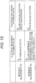
- Fig. 13 illustrates information that is obtained by combining the failure detection according to the electronic watermark and the failure detection according to the impedance measurement. Furthermore, hereinafter, OK indicates that there is no failure detection, and NG indicates that there is failure detection.
- failure detection device 30 There is a failure in the failure detection device 30 (the sound generating device 10 and the speaker 11 are normal, but the failure detection device 30 fails), or there is a failure in the microphone 12 (the sound generating device 10 and the failure detection device 30 are normal, but the microphone 12 fails)
- One or more of the sound generating device 10, the failure detection device 30, the impedance measurement device 60, the speaker 11, and the microphone 12 definitely fail. That is, it is obvious that the failure detection system 100 is not capable of being used.
- the electronic watermark and the impedance measurement are combined, and thus, a faulty spot is easily specified.
- the failure of the impedance measurement device 60 is detected, and in the combination, as in (iii), the failure of the failure detection device 30 is detected, and thus, the impedance measurement device 60 and the failure detection device 30 are capable of monitoring each other the presence or absence of a failure.
- a mechanism for detecting a failure of the device is required, but in this example, the impedance measurement device 60 monitors the sound generating device 10 and the failure detection device 30, and the failure detection device 30 monitors the sound generating device 10 and the impedance measurement device 60, and thus, another device for detecting the failure of the failure detection device 30 and the impedance measurement device 60 is not necessary.
- a case where a plurality of sound generating devices 10 are mounted on the vehicle 8 will be described.
- the vehicle approach notification sound is not capable of reaching the assumed area due to a large body size, and thus, the plurality of sound generating devices 10 are mounted on one vehicle 8.
- the sound generating device 10 of Example 1 generates the hash table or the pseudorandom number, at random, and thus, a plurality of failure detection devices 30 can be mounted on one vehicle 8.
- Fig. 14 is an example of a diagram describing the plurality of failure detection devices 30 mounted on one vehicle 8.
- the plurality of failure detection devices 30 may be independently subjected to the failure detection, according to a combination of the hash table and a pseudorandom number sequence.
- the combination of the hash table and the pseudorandom number sequence is limited, and thus, it is preferable to use the collation data on which the electronic watermark signal is based, by shifting the collation data.
- the numerical value of 0 to 9 of the collation data is shifted by one value with respect to time, but it is sufficient that the collation data does not have the same numerical value.
- the combination of the hash table and the pseudorandom number sequence is "generated at random with respect to a system activation timing", and even in a case where the hash table and the pseudorandom number sequence are limited, the vehicle 8 is characterized by the hash table and the pseudorandom number sequence, and thus, it is possible to suppress false detection due to the electronic watermark signal of the other vehicle.
- Examples 1 to 3 an example in which the failure detection device 30 is mounted on the vehicle 8, has been described, but the failure detection device 30 of this embodiment can be applied to a device using the speaker 11.
- the failure detection device 30 of this embodiment can be preferably applied to a device that is used only occasionally but is disadvantageous in a case where the device fails at the time of being used.
- Figs. 15A to 15C are external views of several devices using the speaker 11.
- Fig. 15A illustrates a fire alarm
- Fig. 15B illustrates a disaster prevention administration wireless broadcast speaker
- Fig. 15C illustrates a gas alarm, respectively.
- the application is not limited thereto, but the failure detection device 30 of this embodiment can be widely applied to the speaker 11 in the train, a disaster prevention speaker in the building, and the like.
- the failure detection device 30 of Examples 1 to 3 can also be provided in the mobile object other than the vehicle 8.
- the failure detection device 30 of Examples 1 to 3 can also be applied to a two-wheel vehicle, a wheelchair, a light vehicle, a one- or two-seater mobility, a robot, or the like, in addition to the vehicle 8 (including a motorcycle).
- the failure detection device 30 mounted on such a mobile object is a device mounted with a mobile object.
- examples of the device mounted with a mobile object include an in-vehicle device or a navigation device.
- the vehicle approach notification sound may be referred to as a name suitable for each mounting device.
- the configuration example of Fig. 5 is divided according to a main function, in order to facilitate the understanding of the processing of the failure detection device 30.
- the present invention is not limited by a method of dividing processing unit or a name.
- the processing of the failure detection device 30 can also be divided into more processing units according to the processing contents.
- the processing of the failure detection device 30 can also be divided such that one processing unit includes more processings.
- the electronic watermark signal generating device 23 is an example of an electronic watermark signal generating means
- the electronic watermark signal detection device 40 is an example of a collation data detection means
- the data collation failure determination unit 36 is an example of a failure determination means
- the addition unit 29 is an example of an addition means
- the hash table conversion unit 22 is an example of a first data conversion means
- the data generating unit 21 is an example of a collation data generating means
- the hash table restoration unit 35 is an example of a second data conversion means
- the hash table generating unit 28 is an example of a conversion table generating means
- the gain adjustment unit 26 is an example of a sound volume adjustment means
- the impedance measurement device 60 is an example of a second failure detection device.
Landscapes
- Engineering & Computer Science (AREA)
- Signal Processing (AREA)
- Physics & Mathematics (AREA)
- Acoustics & Sound (AREA)
- Health & Medical Sciences (AREA)
- Otolaryngology (AREA)
- General Health & Medical Sciences (AREA)
- Computational Linguistics (AREA)
- Audiology, Speech & Language Pathology (AREA)
- Human Computer Interaction (AREA)
- Multimedia (AREA)
- Soundproofing, Sound Blocking, And Sound Damping (AREA)
- Circuit For Audible Band Transducer (AREA)
- Emergency Alarm Devices (AREA)
Abstract
Description
- The present invention relates to a failure detection device, a failure detection system, and a failure detection method.
- An eco-car with less discharge amount of exhaust gas or carbon dioxide, such as an electrical vehicle, a hybrid vehicle, a plug-in hybrid vehicle, or a fuel cell vehicle, has been in widespread use. There are various factors such as a demand for improving fuel consumption (electricity consumption), a reduction in an environmental load, and technical innovation, but it is expected that the eco-car will be in widespread use, in the future. However, the eco-car traveling by a motor, does not make a traveling sound that is generated by an internal combustion such as a reciprocating engine, and thus, it has been pointed out that it is difficult for a pedestrian or the like to recognize the approach of the eco-car. For example, there is a case where a person with impaired vision perceives the approach of a vehicle by the traveling sound, but an expert or the like has pointed out that it is difficult to recognize the approach in the case of the eco-car traveling by the motor.
- For this reason, in the eco-car capable of traveling only by the motor, a sound generating device (also referred to as a vehicle approach notification device) notifying the surroundings that a vehicle has approached, is obligatorily provided in a vehicle, according to the country or the region. In addition, it is expected that the countries or the regions where the sound generating device will be obligatorily provided in the vehicle, in the future, but not at the moment, will increase.
- The sound generating device is set to output a sound in a determined operation condition (referred to as a vehicle approach notification sound) in a case where a vehicle travels at a vehicle speed of less than or equal to a predetermined value at which the traveling sound, a road noise, or the like decreases, and in a case where a vehicle travels back. Then, in a situation where the operation condition is satisfied, the sound generating device is required to be reliably operated, in order to ensure the safeness of the pedestrian or the like.
-
Figs. 1A and 1B are examples of diagrams describing a correspondence between the operation of the sound generating device and the pedestrian. As illustrated inFig. 1A , in a case where an in-vehicle sound generating device is normally operated, the sound generating device outputs the vehicle approach notification sound from a speaker, and thus, apedestrian 9 is capable of recognizing the approach of avehicle 8. In contrast, as illustrated inFig. 1B , in a case where the sound generating device fails, the vehicle approach notification sound is not output, and thus, it is difficult for thepedestrian 9 to recognize the approach of thevehicle 8. - In a case where a driver recognizes the failure of the sound generating device, the driver is capable of handling the failure in some way, but it is originally difficult for the driver to recognize the failure of the sound generating device. It is considered that this is because the sound generating device outputs a sound to the outside of the vehicle, the vehicle approach notification sound is not output in a case where the operation condition is not satisfied, and the like.
- There is a method in which the sound generating device actually outputs an approximant, and the approximant is confirmed by being detected with a microphone, as a method of detecting the failure of the sound generating device. In addition, there is a method of measuring the impedance of the speaker, as a detection method of a failure of the speaker used for outputting the vehicle approach notification sound (for example, refer to Patent Literature 1).
- Patent Literature 1:
JP 2003-274491 A - However, in the method of actually outputting the approximant or the method of measuring the impedance of the speaker, it is not possible to detect the failure of the sound generating device in a state where the vehicle approach notification sound is not output. The operation condition is satisfied in a case where the pedestrian has already approached, but the sound generating device fails, and thus, the vehicle approach notification sound is not output, and therefore, even in a case where the failure is detected, it is difficult for the driver to handle the failure. For this reason, in the failure detection of the sound generating device, it is required that the presence or absence of the failure can be determined before the operation condition is satisfied. It is more preferable that the failure can be detected immediately after the sound generating device fails (in real time) or before the failure.
- In addition, in the method of actually outputting the vehicle approach notification sound, there is a possibility of "false detection as an environment sound". In addition, in the method of measuring the impedance of the speaker, "it is not possible to detect whether or not a sound is actually output".
- In consideration of the problems described above, an object of the present invention is to provide a failure detection device capable of detecting a failure of a sound generating device even in a state where a sound is not output.
- The invention relates to a failure detection device and a failure detection method according to the appended claims. Embodiments are disclosed in the dependent claims. An aspect of the present invention relates to a failure detection device configured to detect a failure of a sound generating device outputting a sound based on sound data from a speaker, the device including: an electronic watermark signal generating means configured to generate an electronic watermark signal including collation data used for collation of whether or not a sound is output from the speaker; the speaker configured to output the electronic watermark signal as a sound; a microphone configured to collect the sound output from the speaker; a collation data detection means configured to detect the collation data from the electronic watermark signal included in the sound collected by the microphone; and a failure determination means configured to determine the presence or absence of the failure of the sound generating device, by collating the collation data detected by the collation data detection means, with the collation data included in the electronic watermark signal by the electronic watermark signal generating means.
- It is possible to provide a failure detection device capable of detecting a failure of a sound generating device even in a state where a sound is not output.
-
Figs. 1A and 1B are examples of diagrams describing a correspondence between an operation of a sound generating device and a pedestrian. -
Fig. 2 is an example of a diagram describing a mechanism at the time of detecting a failure of the sound generating device. -
Figs. 3A and 3B are examples of diagrams describing a failure detection system. -
Fig. 4 is an example of a diagram describing the overall flow when a failure detection device detects a failure. -
Fig. 5 is an example of a functional block diagram illustrating the function of a failure detection device in a block according to an embodiment. -
Fig. 6 is an example of a diagram describing the processing of a binary signal conversion unit. -
Fig. 7 is an example of a diagram describing spread with a pseudorandom number. -
Fig. 8 is an example of a diagram schematically illustrating the addition of an electronic watermark signal to a vehicle approach notification sound. -
Fig. 9 is a diagram illustrating an example of a stego-signal to which the vehicle approach notification sound and the electronic watermark signal are added. -
Fig. 10 is an example of a diagram illustrating the vehicle approach notification sound with an electronic watermark (the stego-signal), which is reversely spread. -
Fig. 11 is an example of a flowchart illustrating the procedure of gain adjustment. -
Fig. 12 is a configuration diagram of an example of a failure detection system (Example 2) according to an embodiment. -
Fig. 13 is an example of a diagram illustrating information that is obtained by combining failure detection according to the electronic watermark and failure detection according to impedance measurement. -
Fig. 14 is an example of a diagram describing a plurality of failure detection devices mounted on one vehicle. -
Figs. 15A to 15C are examples of external views of several devices using a speaker. - Hereinafter, a failure detection device, and a failure detection method performed by the failure detection device will be described with reference to the drawings, as an example of a mode for carrying out the invention.
- A basic mechanism for failure detection of a sound generating device will be described by using
Fig. 2. Fig. 2 is an example of a diagram describing a mechanism at the time of detecting a failure of the sound generating device. A failure detection device of this embodiment performs failure detection by embedding (adding) an electronic watermark with respect to an acoustic signal, and by detecting the electronic watermark. - (1) First, collation data d1 prepared in advance, is spread with a pseudorandom number d2, and thus, an electronic watermark signal d3 is generated.
- (2) The electronic watermark signal d3 is added to a vehicle approach notification sound d4, and thus, a stego-signal is generated. Furthermore, the sound volume of the electronic watermark signal is limited to be masked by the vehicle approach notification sound.
- (3) A stego-signal d5 is subjected to DA conversion, and is output from a
speaker 11. - (4) The stego-signal d5 output from the
speaker 11, is collected by amicrophone 12, and is subjected to AD conversion. The sound volume of the electronic watermark signal is limited to be masked by the vehicle approach notification sound, and thus, the stego-signal d5 has a waveform close to the vehicle approach notification sound d4, but is actually different. - (5) The failure detection device reversely spreads again the stego-signal d5, with the same pseudorandom number. Then, the vehicle approach notification sound is spread, and the collation data d1 is demodulated. Therefore, it is possible to detect a failure of the
speaker 11 and the sound generating device, according to whether or not the collation data output as an electronic watermark, is demodulated (it is also possible to assume a possibility that themicrophone 12 fails). - In a situation where an operation condition of outputting the vehicle approach notification sound, is not satisfied, it is possible to output only the collation data, and thus, it is possible to constantly detect the failure of the sound generating device. The electronic watermark signal masked by the vehicle approach notification sound, is output, and thus, even when the vehicle approach notification sound is output, it is possible to detect the failure of the sound generating device. Therefore, it is possible to detect the failure of the sound generating device and the
speaker 11, immediately after the sound generating device fails (in real time). - In addition, unlike the method of actually outputting the vehicle approach notification sound, it is also possible to almost eliminate the possibility of the "false detection as an environment sound". In addition, unlike the method of measuring the impedance of the
speaker 11, it is possible to perform detection including whether or not a sound is actually output. - The failure indicates that a normal motion is impaired. The failure also indicates that there is a difficulty in the provision of a function, there are some abnormalities, and the like.
- The electronic watermark indicates that some information items are embedded in the digital data, or indicates the embedded information. There are two types of electronic watermarks of a perceptible watermark and a perceiving-difficult watermark. In this embodiment, the perceiving-difficult watermark is preferable, but the perceptible watermark may be used.
- A system configuration example when the failure detection device detects the failure of the sound generating device, will be described by using
Figs. 3A and 3B. Figs. 3A and 3B are examples of diagrams describing the failure detection system.Fig. 3A is a configuration example of asound generating device 10 of the related art, which is illustrated for comparison. In the related art, thesound generating device 10 directly outputs the vehicle approach notification sound from thespeaker 11. When the failure is detected, the impedance of thespeaker 11 is measured, or the voice output from thespeaker 11 is collected by themicrophone 12. -
Fig. 3B is a configuration diagram of an example of afailure detection system 100 of this embodiment. In this embodiment, asound generating device 10 and afailure detection device 30 are electrically connected to each other such that communication can be performed therebetween. Accordingly, thesound generating device 10 is capable of transmitting the vehicle approach notification sound to thefailure detection device 30. Thefailure detection device 30 constantly outputs the collation data from thespeaker 11. Therefore, when the vehicle approach notification sound is output, the vehicle approach notification sound is output by being embedded with the collation data (the electronic watermark signal). In a case where the vehicle approach notification sound is not output, only the collation data (the electronic watermark signal) is output. The electronic watermark is so called in the case of being embedded in host data (in this embodiment, the vehicle approach notification sound), and there is a concern that the electronic watermark is not referred to as the "electronic watermark" in a case where only the collation data is output, but in this embodiment, for the sake of the convenience of description, even in a case where only collation data is output, the electronic watermark is not referred to as the "electronic watermark" without being without any distinction. - Furthermore, constantly indicates that the failure detection can be performed when the failure detection is required to be performed, and it is not necessary to output the collation data without any pause. For example, the output of the collation data may be stopped during the parking or stopping. In addition, in a case where a battery level is less than a threshold value, the output of the collation data may be stopped. In addition, ON/OFF of the output of the collation data can be performed according to a manipulation of a driver.
- The
microphone 12 collects the vehicle approach notification sound with the collation data (the electronic watermark signal) (referred to as the stego-signal), or only the collation data (the electronic watermark signal), and inputs the collected sound to thefailure detection device 30. Thefailure detection device 30 verifies the collation data, and determines the presence or absence of a failure of thesound generating device 10. In a case where it is detected that there is a failure, thefailure detection device 30 displays the effect that thesound generating device 10 fails, on adisplay device 13. The effect that there is a failure, may be notified to a server through a mobile telephone network or the like. Furthermore, thedisplay device 13 may be a meter panel, or may be a display of a navigation device. In addition, thedisplay device 13 may be a head up display (HUD). - In addition, the illustrated configuration is merely an example, and the
failure detection device 30 may include thesound generating device 10, or thesound generating device 10 may include thefailure detection device 30. For example, in a case where the navigation device has the function of thesound generating device 10, the navigation device outputs the vehicle approach notification sound, and detects the failure of thesound generating device 10. In addition, a display audio or a connected audio, but not the navigation device, may function as thesound generating device 10 and thefailure detection device 30. The display audio (or the connected audio) is a device mainly providing an audio visual (AV) function and a communication function, without having a navigation function. - Furthermore, the
failure detection device 30 is a device referred to as an information processing device, a microcomputer, a control device, or the like, including a CPU, a RAM, a flash memory, an input and output I/F, and the like. Thefailure detection device 30 realizes the following functions or means by executing a program decompressed to the RAM from the flash memory, with the CPU. - A processing flow when the
failure detection device 30 detects the failure of thesound generating device 10, will be described by usingFig. 4. Fig. 4 is a diagram describing the overall flow when thefailure detection device 30 detects a failure. - The
failure detection device 30 generates the collation data. The collation data embedded in the vehicle approach notification sound, is data having consecutiveness in chronological order. In the example ofFig. 4 , the collation data is a numerical value counted up one by one, such as "0, 1, 2, 3, 4, 5, 6, 7, 8, and 9". The numerical number returns to "0" after "9". The collation data is the data generated on the basis of such a rule, and thus, when thefailure detection device 30 collates the collation data, it is not possible to specify the collation data output from the speaker. - It is natural that the numerical value such as 0 to 9, is an example. The collation can be performed with any numerical value, and may be performed with an alphabet (a character) or a symbol in addition to the numerical value. However, it is preferable that a bit number of the collation data is short. This is because 1 bit is multiplexed as described below, in order to improve a detection accuracy of data at the time of demodulation, and thus, in a case where the bit number of the original collation data is short, a signal length of the collation data after multiplexing is short. That is, it is possible to embed the collation data for a short time, and it is also possible to perform the detection for a short time. Furthermore, a bit number necessary for 0 to 9, is 4 bits.
- The
failure detection device 30 converts the collation data into a hash value in a hash table (an example of the collation data after conversion). This is because in a case where the samefailure detection device 30 exists in the surroundings, it is assumed that the electronic watermark signal of thefailure detection device 30 is input as an environment sound. In a case where the nearbyfailure detection device 30 outputs the same numerical value at the same timing, there is a concern that the otherfailure detection device 30 performs false detection with respect to the output numerical value. In order to prevent such false detection, the collation data is converted into the hash value in the hash table. The consecutive numerical values in chronological order are randomly changed according to the hash table, and thus, it is possible to reduce a possibility that the same numerical value is output at the same timing. - In a case where the nearby
failure detection device 30 uses the same hash table, the hash values after the conversion become the same, and thus, a plurality of hash tables are prepared, and thefailure detection device 30 switches the hash table at random, at the time of activating a vehicle system (corresponding to ignition ON of a vehicle traveling by an internal combustion). Accordingly, it is possible to reduce a possibility that an electronic watermark signal output by thefailure detection device 30 of theother vehicle 8 is subjected to the false detection. - The
failure detection device 30 generates the electronic watermark signal by multiplying the collation data and the pseudorandom number together. Furthermore, when the vehicle approach notification sound is output, the vehicle approach notification sound with the collation data in which the electronic watermark signal is embedded in the vehicle approach notification sound (the electronic watermark signal) (the stego-signal), is generated. The size (the sound volume) of the electronic watermark signal is limited to be masked by the vehicle approach notification sound or the environment sound. It is sufficient that the pseudorandom number is capable of spreading the collation data, and the pseudorandom number will be referred to as an M-sequence in spread codes. A spread code such as a PN-sequence and a Gold-sequence may be used in addition to the M-sequence. - In a case where the same
failure detection device 30 exists in the surroundings, and the same pseudorandom number is used, the nearbyfailure detection device 30 demodulates the output electronic watermark signal. In this case, the hash table used by the nearbyfailure detection device 30 is assumed as being different, and the output collation data and the restored collation data are different from each other, and thus, there is a concern that thefailure detection device 30 does not fail, but is falsely detected as failing. Therefore, thefailure detection device 30 switches the pseudorandom number at random, at the time of activating the system. Accordingly, even in a case where the samefailure detection device 30 exists in the surroundings, it is not possible to demodulate the electronic watermark signal output by the nearbyfailure detection device 30, and it is possible to reduce a concern that thefailure detection device 30 does not fail, but is falsely detected as failing. - The
failure detection device 30 collects the vehicle approach notification sound with the collation data (the electronic watermark signal), or only the collation data (the electronic watermark signal), with themicrophone 12, and detects the hash value by multiplying the collected sound and the pseudorandom number together, as described above. - The
failure detection device 30 restores the collation data from the hash value, by using the hash table at the time of converting the collation data into the hash value. - The
failure detection device 30 verifies whether or not the collation data output as the electronic watermark, is detected, and thus, performs the failure determination. A case where a part of the collation data of 0 to 9 is dropped without being detected due to the environment sound or the like, or a case where a part of the collation data of 0 to 9 is falsely detected as another value, is assumed, and thus, the presence or absence of a failure is comprehensively determined at an accuracy rate of the collation data of a constant number. For example, in the example ofFig. 4 , in the numerical values of 0 times to 9 times, the collation data is not correctly detected at the first time and the ninth time, but the collation data is correctly detected in the remaining 8 times. Thus, in a case where the accuracy rate is greater than or equal to a threshold value, it is possible to determine that there is no failure. Furthermore, in failure determination, in a case where the collation data is not capable of being correctly detected consecutive N times, it may be determined that there is a failure. - The output and the detection of the electronic watermark signal will be described in detail, by using
Fig. 5. Fig. 5 illustrates a functional block diagram illustrating the function of thefailure detection device 30 in a block. In addition,Fig. 5 illustrates a flow in which each function of thefailure detection device 30 outputs and detects the electronic watermark signal. - A
data generating unit 21 generates the collation data of 0 to 9, in the order. A time for retaining one numerical value, is determined in advance, according to a bit rate [bps] of the electronic watermark signal. - A hash
table generating unit 28 generates the hash table that converts equally 0 to 9 into the hash value of 4 bits, at random, at the time of activating the system, or the like. Examples of the hash table are shown in Table 1. The collation data converted in a certain hash table, is not capable of being restored unless the hash tables are the same, and thus, it is possible to reduce a concern that the electronic watermark signal output by anotherfailure detection device 30 is restored.[Table 1] Numerical Value Hash Value 0 1110 1 0010 2 0101 3 1001 4 0111 5 0000 6 1000 7 0101 8 1100 9 0100 - A hash
table conversion unit 22 converts the collation data into the hash value, in the hash table generated by the hashtable generating unit 28. The hash value is input into an electronic watermarksignal generating device 23. - The electronic watermark
signal generating device 23 includes a binarysignal conversion unit 24, aspread unit 25, and again adjustment unit 26. The binarysignal conversion unit 24multiplexes 1 bit of the hash value into 8 bits, and replaces "0" with "-1". Therefore, a binary signal of 32 bits is obtained. -
Fig. 6 is an example of a diagram describing the processing of the binarysignal conversion unit 24.Fig. 6(a) illustrates the hash value. The binarysignal conversion unit 24 multiplexes the hash value into 8 bits.Fig. 6(b) illustrates the multiplexed hash value. To which bit the hash value is multiplexed, is determined to be an S/N ratio at which the electronic watermark signal can be detected. Therefore, the hash value may be multiplexed into any bit other than 8 bits. In general, it is advantageous to detect the electronic watermark signal, as a bit number of the multiplex increases. This is because the total (more specifically, the average) of the electronic watermark signals for a time of being multiplexed, is used at the time of detecting the electronic watermark signal. - Next, the binary
signal conversion unit 24 replaces "0" with "-1". "1" may be left as it is.Fig. 6(c) illustrates the hash value after the multiplexing in which "0" is replaced with "-1". "1" is left as it is, and "0" is replaced with "-1", and thus, in a case where the pseudorandom number is multiplied twice (spread and reverse spread), the original hash value is obtained. - Return to
Fig. 5 . Thespread unit 25 spreads the hash value that is converted by the binarysignal conversion unit 24, with the pseudorandom number generated by a pseudorandom numbersequence generating unit 27. Specifically, the pseudorandom number and the hash value are multiplied together. The hash value of 4 bits is multiplexed into 8 bits each to be 32 bits, but the pseudorandom number spreads 1 bit, and thus, the length of the pseudorandom number is a digit number (also referred to as a chip) capable of sufficiently spreading 1 bit. -
Fig. 7 is an example of a diagram describing the spread according to the pseudorandom number.Fig. 7(a) illustrates the hash value after the multiplexing in which "0" is replaced with "-1",Fig. 7(b) illustrates an example of the pseudorandom number, andFig. 7(c) illustrates the electronic watermark signal. As illustrated inFig. 7(c) , the original signal (the hash value) is spread with the pseudorandom number. - Return to
Fig. 5 . Thegain adjustment unit 26 decreases the sound volume of the electronic watermark signal to be masked by the vehicle approach notification sound or the environment sound. In the case of being represented by a gain [dB], the electronic watermark signal decreases with a gain of a negative value. How the sound volume is adjusted at the time of being output from thespeaker 11, may be experimentally determined. For example, in a case where the vehicle approach notification sound is a signal of 65536 gradations (16 bits), the maximum sound volume corresponds to 65536. In such sound volume, the sound volume of the electronic watermark signal is adjusted to be detected after being collected by themicrophone 12 and to be masked. For example, in a case where "1" of the electronic watermark signal corresponds to 65536, the sound volume decreases such that the electronic watermark signal decreases from a few hundredth to a few thousandth. The electronic watermark signal may be masked, the sound volume of the electronic watermark may be less than that of the vehicle approach notification sound, or the vehicle approach notification sound may increase. The same applies to the environment sound, and the details will be described below. - Next, an
addition unit 29 adds the electronic watermark signal to the vehicle approach notification sound. There is a case where such addition processing is referred to as "embedment". In a case where the vehicle approach notification sound is not output, theaddition unit 29 transmits only the electronic watermark signal to thespeaker 11 without performing the addition. -
Fig. 8 is an example of a diagram schematically illustrating the addition of the electronic watermark signal with respect to the vehicle approach notification sound.Fig. 8(a) illustrates the waveform of the vehicle approach notification sound (digital),Fig. 8(b) illustrates an example of the electronic watermark (digital) to be embedded, andFig. 8(c) illustrates an example of the stego-signal to which the vehicle approach notification sound and the electronic watermark signal are added. - In
Fig. 8 , it is described that the sound volume of the electronic watermark signal is adjusted in advance with respect to the sound volume of the vehicle approach notification sound. In a case where the electronic watermark signal is +1, the vehicle approach notification sound increases to correspond to +1, and in a case where the electronic watermark signal is -1, the vehicle approach notification sound decreases to correspond to +1. The electronic watermark signal of 8 bits × 4 = 32 bits is subjected to such addition processing. - When the sound data is output from the speaker as a sound, the sound data is represented by a bit sequence of 1 and 0, on the basis of a bit depth (for example, 8 bits, 16 bits, 24 bits, and the like), and is output from the speaker on the basis of a bit rate [bps] of the vehicle approach notification sound. Therefore, a time required for outputting the electronic watermark signal of 32 bits, is changed according to the bit rate, and thus, as described above, the
data generating unit 21 generates the collation data of 0 to 9 at a timing according to the bit rate. - In order to describe the detection of the electronic watermark signal, a graph of another stego-signal is illustrated in
Fig. 9. Fig. 9 illustrates an example of the stego-signal to which the vehicle approach notification sound and the electronic watermark signal are added. InFig. 9 , a solid line represents the vehicle approach notification sound, and a dotted line represents the stego-signal. Furthermore, a horizontal axis is a sampling time, and a vertical axis is an amplitude of the sound volume. The vehicle approach notification sound is slightly different from the stego-signal due to the electronic watermark. - Return to
Fig. 5 . The vehicle approach notification sound with an electronic watermark (the stego-signal) or the electronic watermark signal is sound data of vibrating thespeaker 11. The sound data is subjected to DA conversion while the signal is transmitted to thespeaker 11 from theaddition unit 29. Thespeaker 11 performs DA conversion with respect to the vehicle approach notification sound with an electronic watermark (the stego-signal) or the electronic watermark signal, subjected to the DA conversion, and outputs a sound including the DA-converted sound or signal. Furthermore, the DA conversion may be performed by thespeaker 11. - Next, the
microphone 12 collects the vehicle approach notification sound with an electronic watermark (the stego-signal) or the electronic watermark signal. The vehicle approach notification sound with an electronic watermark (the stego-signal) or the electronic watermark signal is subjected to AD conversion to be a digital signal, and is input into an electronic watermarksignal detection device 40. - The electronic watermark
signal detection device 40 includes areverse spread unit 31, afixed period counter 32, a bitdata restoration unit 33, and acorrelation calculation unit 34. - First, the
reverse spread unit 31 reversely spreads the vehicle approach notification sound with an electronic watermark (the stego-signal) or the electronic watermark signal, with the pseudorandom number. The reverse spread and the spread have the same arithmetic contents. In the spread, a portion multiplied by 1, is left as 1, and a portion multiplied by -1, is returned to 1. On the other hand, in the stego-signals, the vehicle approach notification sound is spread, and thus, is regarded as a noise. Therefore, it is possible to restore the electronic watermark signal, and to eliminate the vehicle approach notification sound. -
Fig. 10 illustrates an example of a diagram illustrating the vehicle approach notification sound with an electronic watermark (the stego-signal) which is reversely spread. InFig. 10 , a solid line represents the reversely spread electronic watermark signal, and consecutive "○" represents the spread vehicle approach notification sound. The electronic watermark signal is multiplied by the pseudorandom number twice at the time of the spread and the reverse spread, and thus, is restored to the multiplexed hash value. - The
correlation calculation unit 34 performs correlation calculation with respect to the stego-signal and a pseudorandom number signal to be sequentially input while shifting one sampling period, according to a mutual correlation function as the following expression. X(t) is the pseudorandom number signal, and Y(t + τ) is the stego-signal.
- Therefore, the
correlation calculation unit 34 performs the same calculation as that of thereverse spread unit 31, and adds each multiplication result. According to the correlation calculation, a timing when the pseudorandom number and the stego-signal are synchronized, appears. The timing is identical to the length of the pseudorandom number, but the result of the correlation calculation represents a peak at a synchronization timing (becomes almost zero due to the properties of the pseudorandom number unless the synchronization is performed). Therefore, it is possible to detect that the synchronization with the electronic watermark signal is obtained, according to the peak. Furthermore, specifically, in a case where Cxy is greater than or equal to a threshold value, it is determined that the synchronization is obtained. When the synchronization is obtained, thecorrelation calculation unit 34 transmits timing notification to thefixed period counter 32 and the bitdata restoration unit 33. - The bit
data restoration unit 33 restores the bit data by 8 bits that is a multiplex number, triggered by the timing notification. The multiplexed hash value is obtained by the reverse spread, but the value of the data collected by themicrophone 12 is not "+1" or "-1''. However, the portion corresponding to "+1" is definitely a positive value, and the portion corresponding to "-1" is definitely a negative value. Therefore, the bitdata restoration unit 33 obtains the average of the amplitudes at every 8 bits, restores "+1" in the case of a positive value, and restores "0" in the case of a negative value. Accordingly, the hash value before the multiplexing is obtained. The bitdata restoration unit 33 transmits the restored hash value before the multiplexing, to a hashtable restoration unit 35. - On the other hand, fixed
period counter 32 performs a count for a constant period (8 bits × 4 bits), triggered by the timing notification. In a case where there is no next timing notification within a time limit (for example, Time + α for counting 32 bits), it is determined as being undetected. Thefixed period counter 32 transmits undetected notification to the bitdata restoration unit 33. This is because the case of being undetected indicates a case where the electronic watermark signal is not capable of being detected due to the environment sound or the like, and thus, the bit data is not capable of being correctly restored. According to the undetected notification, the bitdata restoration unit 33 is capable of ending the restoration of the bit data. - The hash
table restoration unit 35 searches the hash value from the hash tables generated by the hashtable generating unit 28, and specifies the collation data associated with the hash value. Accordingly, the collation data converted into the electronic watermark signal, is obtained. - A data collation
failure determination unit 36 determines whether or not the collation data transmitted as the electronic watermark signal, is coincident with the collation data specified with the hash table. In a case where the accuracy rate is not less than or equal to the threshold value, or the collation data transmitted as the electronic watermark signal, is not coincident with the collation data specified with the hash table, consecutively N times, it is determined that any one of thesound generating device 10, thespeaker 11, and themicrophone 12, fails. - It is preferable that the
gain adjustment unit 26 changes an adjustment amount of the gain in a case where the vehicle approach notification sound is output and in a case where the vehicle approach notification sound is not output. This is because in a case where the vehicle approach notification sound is not output, the electronic watermark signal is masked by the environment sound, but the vehicle approach notification sound and the environment sound do not necessarily have the same sound volume. Originally, the environment sound is not constant. In addition, it is preferable that the electronic watermark signal is output with the maximum sound volume that apedestrian 9 is not capable of hearing, such that the restoration is easily performed. - Therefore, the
gain adjustment unit 26 adjusts the gain as follows.Fig. 11 is an example of a flowchart illustrating the procedure of gain adjustment. The processing ofFig. 11 , for example, is periodically executed while the electronic watermark signal is output. - The
gain adjustment unit 26 determines whether or not the vehicle approach notification sound is output (S10). For example, whether or not the vehicle approach notification sound is input into thefailure detection device 30 from thesound generating device 10, is determined. Thegain adjustment unit 26 may inquire thesound generating device 10, or thegain adjustment unit 26 may determine whether or not the operation condition of thesound generating device 10 is satisfied. - In a case where the determination of Step S10 is Yes, the
gain adjustment unit 26 adjusts the sound volume of the electronic watermark signal with the gain determined in advance (S20). The sound volume of the vehicle approach notification sound, for example, is reduced from a few hundredth to a few thousandth. Furthermore, in a case where the gain is represented by [dB], the gain is a negative value. - In a case where the determination of Step S10 is No, the
gain adjustment unit 26 acquires the speed of a mobile object (in the case of a vehicle, a vehicle speed) (S30). This is because the vehicle speed is easily affected by the environment sound. - The
gain adjustment unit 26 adjusts the sound volume with the gain determined according to the vehicle speed (S40). The sound volume of the electronic watermark signal may increase as the vehicle speed increases. Therefore, the sound volume of the electronic watermark signal decreases as the vehicle speed decreases. Furthermore, in general, the sound volume of the vehicle approach notification sound is greater than the sound volume of the environment sound, and thus, in a case where the vehicle approach notification sound is not output, the sound volume of the electronic watermark signal decreases, compared to a case where the vehicle approach notification sound is output. - Thus, it is possible to adjust whether or not the vehicle approach notification sound is output, and to adjust the electronic watermark signal to have the optimal sound volume with respect to the environment sound.
- Furthermore, the gain is not determined according to the vehicle speed, but the sound volume of the environment sound may be actually acquired by the
microphone 12, and the sound volume of the electronic watermark signal may be reduced on the basis of the sound volume. - As described above, in the
failure detection device 30 of this embodiment, the collation data can be output by being masked by the vehicle approach notification sound or the environment sound, and thus, even when the vehicle approach notification sound is not output, it is possible to detect the failure of thesound generating device 10. For example, it is possible to detect the failure immediately after thesound generating device 10 fails. - In addition, unlike the method of actually outputting the vehicle approach notification sound, it is also possible to almost eliminate the possibility of the "false detection as an environment sound". In addition, unlike the method of measuring the impedance of the
speaker 11, it is possible to perform detection including whether or not a sound is actually output. - In this example, the
failure detection device 30 detecting the failure of thesound generating device 10, in conjunction with impedance measurement, will be described. The electronic watermark is originally performed in the state of a poor S/N ratio, and thus, tends to be difficult to retain a detection accuracy. In this example, the impedance measurement and thefailure detection device 30 of Example 1 are combined, and thus, it is possible to more reliably detect a failure. - As described in Example 1, the
failure detection device 30 outputs the electronic watermark signal, and thus, thespeaker 11 is constantly in a driving state, and therefore, it is possible to constantly perform the failure detection according to the impedance measurement. In addition, a failure detection result according to the electronic watermark, and a failure detection result according to the impedance measurement are combined, and thus, a faulty spot can be specified, and thefailure detection device 30 and an impedance measurement device are capable of monitoring each other. -
Fig. 12 illustrates a configuration diagram of an example of thefailure detection system 100 of this example. The configuration of thefailure detection device 30 is identical to that of Example 1. InFig. 12 , animpedance measurement device 60 is connected to thespeaker 11, and adetection circuit 61 measures the impedance of thespeaker 11 from a current and a voltage flowing into thespeaker 11. In a case where the inside of thespeaker 11 is disconnected, a current does not flow into thespeaker 11, and thus, it is possible to detect the disconnection by comparing a threshold value with the impedance. Furthermore, it is sufficient that thedetection circuit 61 of this embodiment is configured to measure the impedance. For example, a specified alternating-current voltage is applied to thesound generating device 10 and thespeaker 11, and the current flowing into thespeaker 11 is detected, and thus, theimpedance measurement device 60 is capable of calculating the impedance. - Furthermore, a resistance value with respect to a direct current may be detected, instead of the impedance, and the disconnection may be detected on the basis of the resistance value.
- In addition, the configuration of
Fig. 12 is an example, and thefailure detection device 30 may include theimpedance measurement device 60. Thefailure detection device 30 may acquire a determination result of the presence or absence of a failure, from theimpedance measurement device 60. -
Fig. 13 illustrates information that is obtained by combining the failure detection according to the electronic watermark and the failure detection according to the impedance measurement. Furthermore, hereinafter, OK indicates that there is no failure detection, and NG indicates that there is failure detection. - There is no failure in the
sound generating device 10, thefailure detection device 30, theimpedance measurement device 60, thespeaker 11, and themicrophone 12. That is, there is no abnormality in thefailure detection system 100. - There is a failure in the impedance measurement device 60 (actually, the
speaker 11 is not disconnected), or there is false detection of the electronic watermark signal of the other vehicle (thespeaker 11 fails, but the electronic watermark signal of the other vehicle is acquired by the microphone 12) - There is a failure in the failure detection device 30 (the
sound generating device 10 and thespeaker 11 are normal, but thefailure detection device 30 fails), or there is a failure in the microphone 12 (thesound generating device 10 and thefailure detection device 30 are normal, but themicrophone 12 fails) - One or more of the
sound generating device 10, thefailure detection device 30, theimpedance measurement device 60, thespeaker 11, and themicrophone 12 definitely fail. That is, it is obvious that thefailure detection system 100 is not capable of being used. - As described above, the electronic watermark and the impedance measurement are combined, and thus, a faulty spot is easily specified. In addition, in the combination of the electronic watermark determination and the impedance measurement, as in (ii), the failure of the
impedance measurement device 60 is detected, and in the combination, as in (iii), the failure of thefailure detection device 30 is detected, and thus, theimpedance measurement device 60 and thefailure detection device 30 are capable of monitoring each other the presence or absence of a failure. In general, in a device detecting a failure of other devices, a mechanism for detecting a failure of the device is required, but in this example, theimpedance measurement device 60 monitors thesound generating device 10 and thefailure detection device 30, and thefailure detection device 30 monitors thesound generating device 10 and theimpedance measurement device 60, and thus, another device for detecting the failure of thefailure detection device 30 and theimpedance measurement device 60 is not necessary. - In this example, a case where a plurality of
sound generating devices 10 are mounted on thevehicle 8, will be described. For example, there is also a case where the vehicle approach notification sound is not capable of reaching the assumed area due to a large body size, and thus, the plurality ofsound generating devices 10 are mounted on onevehicle 8. Thesound generating device 10 of Example 1, generates the hash table or the pseudorandom number, at random, and thus, a plurality offailure detection devices 30 can be mounted on onevehicle 8. -
Fig. 14 is an example of a diagram describing the plurality offailure detection devices 30 mounted on onevehicle 8. In this case, the plurality offailure detection devices 30 may be independently subjected to the failure detection, according to a combination of the hash table and a pseudorandom number sequence. However, the combination of the hash table and the pseudorandom number sequence is limited, and thus, it is preferable to use the collation data on which the electronic watermark signal is based, by shifting the collation data. InFig. 14 , the numerical value of 0 to 9 of the collation data is shifted by one value with respect to time, but it is sufficient that the collation data does not have the same numerical value. - Accordingly, it is sufficient that the combination of the hash table and the pseudorandom number sequence is "generated at random with respect to a system activation timing", and even in a case where the hash table and the pseudorandom number sequence are limited, the
vehicle 8 is characterized by the hash table and the pseudorandom number sequence, and thus, it is possible to suppress false detection due to the electronic watermark signal of the other vehicle. - In Examples 1 to 3, an example in which the
failure detection device 30 is mounted on thevehicle 8, has been described, but thefailure detection device 30 of this embodiment can be applied to a device using thespeaker 11. - For example, the
failure detection device 30 of this embodiment can be preferably applied to a device that is used only occasionally but is disadvantageous in a case where the device fails at the time of being used. - Speaker Type Alarm (Fire Alarm and Gas Leakage Alarm)
- Disaster Prevention Administration Wireless Broadcast Speaker
- Security Warning Device
-
Figs. 15A to 15C are external views of several devices using thespeaker 11.Fig. 15A illustrates a fire alarm,Fig. 15B illustrates a disaster prevention administration wireless broadcast speaker, andFig. 15C illustrates a gas alarm, respectively. The application is not limited thereto, but thefailure detection device 30 of this embodiment can be widely applied to thespeaker 11 in the train, a disaster prevention speaker in the building, and the like. - In addition, the
failure detection device 30 of Examples 1 to 3, can also be provided in the mobile object other than thevehicle 8. For example, thefailure detection device 30 of Examples 1 to 3, can also be applied to a two-wheel vehicle, a wheelchair, a light vehicle, a one- or two-seater mobility, a robot, or the like, in addition to the vehicle 8 (including a motorcycle). Thefailure detection device 30 mounted on such a mobile object, is a device mounted with a mobile object. For example, examples of the device mounted with a mobile object, include an in-vehicle device or a navigation device. In a case where thefailure detection device 30 is mounted on a mobile object other than the vehicle, the vehicle approach notification sound may be referred to as a name suitable for each mounting device. - As described above, the best mode for carrying out the present invention has been described by using the examples, but the present invention is not limited to the examples, and various modifications and substitutions can be performed within a range not departing from the gist of the present invention.
- For example, the configuration example of
Fig. 5 is divided according to a main function, in order to facilitate the understanding of the processing of thefailure detection device 30. The present invention is not limited by a method of dividing processing unit or a name. The processing of thefailure detection device 30 can also be divided into more processing units according to the processing contents. In addition, the processing of thefailure detection device 30 can also be divided such that one processing unit includes more processings. - Furthermore, the electronic watermark
signal generating device 23 is an example of an electronic watermark signal generating means, the electronic watermarksignal detection device 40 is an example of a collation data detection means, the data collationfailure determination unit 36 is an example of a failure determination means, theaddition unit 29 is an example of an addition means, the hashtable conversion unit 22 is an example of a first data conversion means, thedata generating unit 21 is an example of a collation data generating means, the hashtable restoration unit 35 is an example of a second data conversion means, the hashtable generating unit 28 is an example of a conversion table generating means, thegain adjustment unit 26 is an example of a sound volume adjustment means, and theimpedance measurement device 60 is an example of a second failure detection device. -
- 10
- SOUND GENERATING DEVICE
- 11
- SPEAKER
- 12
- MICROPHONE
- 13
- DISPLAY DEVICE
- 30
- FAILURE DETECTION DEVICE
- 40
- ELECTRONIC WATERMARK SIGNAL DETECTION DEVICE
- 60
- IMPEDANCE MEASUREMENT DEVICE
- 100
- FAILURE DETECTION SYSTEM
Claims (10)
- A failure detection device (30) configured to detect a failure of a sound generating device (10) outputting a sound based on sound data from a speaker (11), wherein the failure detection device (30) comprises:an electronic watermark signal generating means (23) configured to generate an electronic watermark signal including collation data used for collation of whether or not a sound is output from the speaker (11);the speaker (11) configured to output the electronic watermark signal as a sound;a microphone (12) configured to collect the sound output from the speaker (11);a collation data detection means (40) configured to detect the collation data from the electronic watermark signal included in the sound collected by the microphone (12); anda failure determination means (36) configured to determine presence or absence of the failure of the sound generating device (10), by collating the collation data detected by the collation data detection means (40), with the collation data included in the electronic watermark signal by the electronic watermark signal generating means (23).
- The failure detection device (30) according to claim 1, characterized in that the electronic watermark signal generating means (23) generates the electronic watermark signal by spreading the collation data with a spread code, and
the spread code is generated at random. - The failure detection device (30) according to claim 2, characterized in that the failure detection device (30) further comprises an addition means (29) configured to add the electronic watermark signal to the sound data when the sound generating device (10) outputs the sound based on the sound data from the speaker (11),
the speaker (11) outputs a stego-signal in which the electronic watermark signal is added to the sound data by the addition means (29), and
the collation data detection means (40) detects the electronic watermark signal from the stego-signal, by reversely spreading the stego-signal with the spread code used for generating the electronic watermark signal. - The failure detection device (30) according to any one of claims 1 to 3, characterized in that the failure detection device (30) further comprises:a collation data generating means (21) configured to generate the collation data;a first data conversion means (22) configured to convert the collation data generated by the collation data generating means (21), into collation data after conversion, in a conversion table; anda second data conversion means (35) configured to convert the collation data after the conversion into the collation data by using the conversion table,the electronic watermark signal generating means (23) generates an electronic watermark signal including the collation data after the conversion, andthe collation data detection means (40) detects the collation data after the conversion from the electronic watermark signal included in the sound collected by the microphone (12).
- The failure detection device (30) according to claim 4, characterized in that the failure detection device (30) further comprises a conversion table generating means (28) configured to generate the conversion table at random.
- The failure detection device (30) according to any one of claims 1 to 5, characterized in that the failure detection device (30) further comprises a sound volume adjustment means (26) configured to adjust sound volume at the time of outputting the electronic watermark signal from the speaker (11) as a sound, and
the sound volume adjustment means (26) changes an adjustment amount of the sound volume according to whether or not the sound generating device (10) outputs the sound based on the sound data from the speaker (11). - The failure detection device (30) according to claim 6, characterized in that the sound generating device (10) and the failure detection device (30) are mounted on a mobile object, and
in a case where the sound generating device (10) does not output the sound based on the sound data from the speaker (11),
the sound volume adjustment means (26) changes the adjustment amount of the sound volume according to a speed of the mobile object. - The failure detection device (30) according to any one of claims 1 to 7, characterized in that the failure detection device (30) is capable of including a second failure detection device (60) configured to electrically detect a failure of the speaker (11), or is capable of acquiring a detection result of the failure of the speaker (11) from the second failure detection device (60), and
the failure determination means (36) determines presence or absence of a failure of the second failure detection device (60) or the failure detection device (30), by combining a determination result of the presence or absence of the failure according to the second failure detection device (60), with a determination result of the presence or absence of the failure according to the failure detection device (30). - A mobile object mounting device on which the failure detection device (30) according to any one of claims 1 to 8 is mounted.
- A failure detection method of a failure detection device (30) configured to detect a failure of a sound generating device (10) outputting a sound based on sound data from a speaker (11), characterized in that the failure detection method comprises:a step of allowing an electronic watermark signal generating means (23) to generate an electronic watermark signal including collation data used for collation of whether or not a sound is output from the speaker (11);a step of allowing the speaker (11) to output the electronic watermark signal as a sound;a step of allowing a microphone (12) to collect the sound output from the speaker (11);a step of allowing a collation data detection means (40) to detect the collation data from the electronic watermark signal included in the sound collected by the microphone (12); anda step of allowing a failure determination means (36) to determine presence or absence of the failure of the sound generating device (10), by collating the collation data detected by the collation data detection means (40), with the collation data included in the electronic watermark signal by the electronic watermark signal generating means (23).
Applications Claiming Priority (1)
| Application Number | Priority Date | Filing Date | Title |
|---|---|---|---|
| JP2018088353A JP7013093B2 (en) | 2018-05-01 | 2018-05-01 | Failure detection device, mobile device, failure detection method |
Publications (2)
| Publication Number | Publication Date |
|---|---|
| EP3565277A1 true EP3565277A1 (en) | 2019-11-06 |
| EP3565277B1 EP3565277B1 (en) | 2022-04-13 |
Family
ID=66323735
Family Applications (1)
| Application Number | Title | Priority Date | Filing Date |
|---|---|---|---|
| EP19171553.1A Active EP3565277B1 (en) | 2018-05-01 | 2019-04-29 | Failure detection device, failure detection system, and failure detection method |
Country Status (4)
| Country | Link |
|---|---|
| US (1) | US10516956B2 (en) |
| EP (1) | EP3565277B1 (en) |
| JP (1) | JP7013093B2 (en) |
| CN (1) | CN110430518B (en) |
Cited By (2)
| Publication number | Priority date | Publication date | Assignee | Title |
|---|---|---|---|---|
| CN111710329A (en) * | 2020-06-12 | 2020-09-25 | 重庆瑞尔科技发展有限公司 | Deep learning-based ship engine voiceprint fault discrimination method and system |
| EP4210049A4 (en) * | 2020-09-30 | 2024-02-21 | Huawei Technologies Co., Ltd. | METHOD AND DEVICE FOR ADDING DIGITAL TATTOO AUDIO, METHOD AND DEVICE FOR ANALYZING DIGITAL TATTOO AUDIO, AND MEDIUM |
Families Citing this family (7)
| Publication number | Priority date | Publication date | Assignee | Title |
|---|---|---|---|---|
| WO2021187449A1 (en) * | 2020-03-18 | 2021-09-23 | ソニーグループ株式会社 | Data processing device, data processing method, data processing program, data extraction device, data extraction method, and data extraction program |
| CN112669883A (en) * | 2020-12-24 | 2021-04-16 | 北京达佳互联信息技术有限公司 | Abnormity checking method and device for audio playing equipment and storage medium |
| JP2022186196A (en) * | 2021-06-04 | 2022-12-15 | マツダ株式会社 | Vehicle sound inspection system and vehicle sound inspection method |
| JP7779713B2 (en) * | 2021-11-30 | 2025-12-03 | ローム株式会社 | Audio output device |
| WO2025178623A1 (en) * | 2024-02-22 | 2025-08-28 | Harman International Industries, Incorporated | System and method for real-time acoustic monitoring of externally mounted microphones and arrays |
| DE102024109127A1 (en) * | 2024-03-28 | 2025-10-02 | Brose Fahrzeugteile Se & Co. Kommanditgesellschaft, Bamberg | Acoustic vehicle warning system with microphone for identifying a warning sound in the vehicle's surroundings and/or a malfunction in a part of the vehicle |
| CN119921887B (en) * | 2025-04-03 | 2025-07-11 | 苏州华启智能科技股份有限公司 | Anomaly self-detection method, system, device and medium for PIS broadcast system |
Citations (6)
| Publication number | Priority date | Publication date | Assignee | Title |
|---|---|---|---|---|
| EP1278183A1 (en) * | 2001-07-19 | 2003-01-22 | Samsung Electronics Co., Ltd. | Voice operated electronic appliance |
| JP2003274491A (en) | 2002-03-18 | 2003-09-26 | Mitsubishi Electric Corp | Speaker disconnection detection device |
| US20120274459A1 (en) * | 2011-04-29 | 2012-11-01 | Panasonic Automotive Systems Company Of America, Division Of Panasonic Corporation Of North America | Method and system for utilizing spread spectrum techniques for in car applications |
| WO2013118250A1 (en) * | 2012-02-07 | 2013-08-15 | 三菱電機株式会社 | Vehicle proximity notification device and failure diagnosing method for same |
| EP2738042A1 (en) * | 2011-07-27 | 2014-06-04 | Anden Co., Ltd. | Vehicle approach warning device |
| EP2871095A1 (en) * | 2012-07-04 | 2015-05-13 | Panasonic Intellectual Property Management Co., Ltd. | Proximity alarm device, proximity alarm system, mobile device, and method for diagnosing failure of proximity alarm system |
Family Cites Families (23)
| Publication number | Priority date | Publication date | Assignee | Title |
|---|---|---|---|---|
| JP2001135020A (en) | 1999-11-05 | 2001-05-18 | Sony Corp | Information transmitting / receiving method, information transmitting method and information receiving method, information transmitting / receiving apparatus, information transmitting apparatus and information receiving apparatus |
| JP5486839B2 (en) | 2009-05-14 | 2014-05-07 | 株式会社日立製作所 | Digital watermark embedding detection method using small detection window |
| JP5306133B2 (en) | 2009-09-25 | 2013-10-02 | 大同信号株式会社 | Railroad crossing warning sound generator |
| JPWO2011121928A1 (en) * | 2010-03-31 | 2013-07-04 | 日本電気株式会社 | Digital content management system, verification apparatus, program thereof, and data processing method |
| WO2011148470A1 (en) * | 2010-05-26 | 2011-12-01 | 三菱電機株式会社 | Simulated sound control device and electrically driven moving body with same |
| US20120045068A1 (en) * | 2010-08-20 | 2012-02-23 | Korea Institute Of Science And Technology | Self-fault detection system and method for microphone array and audio-based device |
| TWI412019B (en) * | 2010-12-03 | 2013-10-11 | Ind Tech Res Inst | Sound event detection module and method thereof |
| CN202106908U (en) * | 2010-12-14 | 2012-01-11 | 上海汽车集团股份有限公司 | Pedestrian protecting device |
| US8589167B2 (en) * | 2011-05-11 | 2013-11-19 | Nuance Communications, Inc. | Speaker liveness detection |
| JP5873964B2 (en) | 2011-05-18 | 2016-03-01 | パナソニックIpマネジメント株式会社 | Vehicle approach notification device |
| JP5820235B2 (en) | 2011-10-26 | 2015-11-24 | 日立マクセル株式会社 | Control terminal and electronic device control system |
| CN102595300B (en) * | 2012-02-13 | 2014-07-23 | 深圳市理邦精密仪器股份有限公司 | Apparatus for detecting faults of loudspeakers and loudspeaker system |
| CN102765350A (en) * | 2012-08-08 | 2012-11-07 | 江苏新日电动车股份有限公司 | Voice warning system for electric vehicle |
| EP2787504A1 (en) * | 2013-04-02 | 2014-10-08 | Thomson Licensing | Method and Apparatus for determining watermark symbols in a received audio signal that can contain echoes, reverberation and/or noise |
| CN203381545U (en) * | 2013-06-08 | 2014-01-08 | 重庆深渝北斗汽车电子有限公司 | Vehicle speed alarm capable of simulating sound of engine |
| JP5975579B2 (en) * | 2014-03-19 | 2016-08-23 | 富士重工業株式会社 | Vehicle approach notification device |
| CN204037444U (en) * | 2014-09-05 | 2014-12-24 | 成都勋迪电动车辆制造有限公司 | Electronlmobil simulated engine audio unit |
| CN205987376U (en) * | 2016-08-17 | 2017-02-22 | 宝沃汽车(中国)有限公司 | Speaker fault monitoring system and vehicle of vehicle |
| CN106921728A (en) * | 2016-08-31 | 2017-07-04 | 阿里巴巴集团控股有限公司 | A kind of method for positioning user, information-pushing method and relevant device |
| CN108419199A (en) * | 2017-02-10 | 2018-08-17 | 阿里巴巴集团控股有限公司 | Fault detection method, device and the equipment of acoustic signals, readable medium |
| CN108631954B (en) * | 2017-03-24 | 2020-12-11 | 电信科学技术研究院 | Data transmission method and device |
| CN207251894U (en) * | 2017-10-18 | 2018-04-17 | 会听声学科技(北京)有限公司 | A kind of active sound-producing device of electric automobile simulation conventional engines |
| CN108430026B (en) * | 2018-03-07 | 2020-08-21 | 广州艾美网络科技有限公司 | Audio equipment failure detection method and singing equipment |
-
2018
- 2018-05-01 JP JP2018088353A patent/JP7013093B2/en active Active
-
2019
- 2019-04-12 CN CN201910291907.0A patent/CN110430518B/en active Active
- 2019-04-17 US US16/387,099 patent/US10516956B2/en active Active
- 2019-04-29 EP EP19171553.1A patent/EP3565277B1/en active Active
Patent Citations (6)
| Publication number | Priority date | Publication date | Assignee | Title |
|---|---|---|---|---|
| EP1278183A1 (en) * | 2001-07-19 | 2003-01-22 | Samsung Electronics Co., Ltd. | Voice operated electronic appliance |
| JP2003274491A (en) | 2002-03-18 | 2003-09-26 | Mitsubishi Electric Corp | Speaker disconnection detection device |
| US20120274459A1 (en) * | 2011-04-29 | 2012-11-01 | Panasonic Automotive Systems Company Of America, Division Of Panasonic Corporation Of North America | Method and system for utilizing spread spectrum techniques for in car applications |
| EP2738042A1 (en) * | 2011-07-27 | 2014-06-04 | Anden Co., Ltd. | Vehicle approach warning device |
| WO2013118250A1 (en) * | 2012-02-07 | 2013-08-15 | 三菱電機株式会社 | Vehicle proximity notification device and failure diagnosing method for same |
| EP2871095A1 (en) * | 2012-07-04 | 2015-05-13 | Panasonic Intellectual Property Management Co., Ltd. | Proximity alarm device, proximity alarm system, mobile device, and method for diagnosing failure of proximity alarm system |
Cited By (2)
| Publication number | Priority date | Publication date | Assignee | Title |
|---|---|---|---|---|
| CN111710329A (en) * | 2020-06-12 | 2020-09-25 | 重庆瑞尔科技发展有限公司 | Deep learning-based ship engine voiceprint fault discrimination method and system |
| EP4210049A4 (en) * | 2020-09-30 | 2024-02-21 | Huawei Technologies Co., Ltd. | METHOD AND DEVICE FOR ADDING DIGITAL TATTOO AUDIO, METHOD AND DEVICE FOR ANALYZING DIGITAL TATTOO AUDIO, AND MEDIUM |
Also Published As
| Publication number | Publication date |
|---|---|
| JP7013093B2 (en) | 2022-01-31 |
| JP2019195127A (en) | 2019-11-07 |
| CN110430518A (en) | 2019-11-08 |
| EP3565277B1 (en) | 2022-04-13 |
| CN110430518B (en) | 2022-08-09 |
| US20190342680A1 (en) | 2019-11-07 |
| US10516956B2 (en) | 2019-12-24 |
Similar Documents
| Publication | Publication Date | Title |
|---|---|---|
| EP3565277B1 (en) | Failure detection device, failure detection system, and failure detection method | |
| US10147247B2 (en) | On-vehicle emergency notification device | |
| DE50312907D1 (en) | SYSTEM FOR ACCIDENT PREVENTION | |
| US8588731B2 (en) | TYY interface module signal to communicate equipment disruption to call center | |
| GB0706686D0 (en) | Superimposing current or previous graphing data for an anamoly detection | |
| CN104333714B (en) | The signal switching method and system of combination | |
| CN101477336A (en) | Vehicle remote independent fault diagnosis method and apparatus | |
| WO2011031629A3 (en) | Network-based identification of uninsured vehicles | |
| CN109658704A (en) | A kind of overspeed of vehicle management method and system | |
| CN105809909A (en) | Electric vehicle and emergency call alarm system and method thereof | |
| CN110797047A (en) | Real-time monitoring device, system and method for vehicle running abnormal sound | |
| CN105430210A (en) | Emergency alarm method and module for mobile terminal | |
| EP4145153B1 (en) | Switch state testing circuit, method and apparatus | |
| US20220229118A1 (en) | Method for indicating a state of a battery of a vehicle | |
| AU2003230803A1 (en) | Systems and method for generating an image | |
| KR20020020574A (en) | Method and Device for transmitting data of vehicle | |
| CN103963723B (en) | Effective vehicle speed acquisition system and acquisition method thereof | |
| US9685062B2 (en) | Electronic device, security warning system and method | |
| CN105160876A (en) | Automobile horn monitoring system | |
| JP4315073B2 (en) | Failure analysis system | |
| CN109586788B (en) | Monitoring system fault diagnosis method, device, computer equipment and storage medium | |
| CN103237304B (en) | Anti-monitor method, Apparatus and system | |
| KR101704169B1 (en) | System of preventing pedestrian traffic accident | |
| CN117641285A (en) | Motorcycle tracking method and system and motorcycle | |
| EP2375630A3 (en) | Systems, devices and methods for outputting alerts to indicate the use of a weak hash function |
Legal Events
| Date | Code | Title | Description |
|---|---|---|---|
| PUAI | Public reference made under article 153(3) epc to a published international application that has entered the european phase |
Free format text: ORIGINAL CODE: 0009012 |
|
| STAA | Information on the status of an ep patent application or granted ep patent |
Free format text: STATUS: THE APPLICATION HAS BEEN PUBLISHED |
|
| AK | Designated contracting states |
Kind code of ref document: A1 Designated state(s): AL AT BE BG CH CY CZ DE DK EE ES FI FR GB GR HR HU IE IS IT LI LT LU LV MC MK MT NL NO PL PT RO RS SE SI SK SM TR |
|
| AX | Request for extension of the european patent |
Extension state: BA ME |
|
| STAA | Information on the status of an ep patent application or granted ep patent |
Free format text: STATUS: REQUEST FOR EXAMINATION WAS MADE |
|
| 17P | Request for examination filed |
Effective date: 20200220 |
|
| RBV | Designated contracting states (corrected) |
Designated state(s): AL AT BE BG CH CY CZ DE DK EE ES FI FR GB GR HR HU IE IS IT LI LT LU LV MC MK MT NL NO PL PT RO RS SE SI SK SM TR |
|
| STAA | Information on the status of an ep patent application or granted ep patent |
Free format text: STATUS: EXAMINATION IS IN PROGRESS |
|
| 17Q | First examination report despatched |
Effective date: 20200731 |
|
| GRAP | Despatch of communication of intention to grant a patent |
Free format text: ORIGINAL CODE: EPIDOSNIGR1 |
|
| STAA | Information on the status of an ep patent application or granted ep patent |
Free format text: STATUS: GRANT OF PATENT IS INTENDED |
|
| RIC1 | Information provided on ipc code assigned before grant |
Ipc: B60Q 5/00 20060101ALN20211104BHEP Ipc: G10L 19/018 20130101ALI20211104BHEP Ipc: H04R 29/00 20060101AFI20211104BHEP |
|
| INTG | Intention to grant announced |
Effective date: 20211130 |
|
| GRAS | Grant fee paid |
Free format text: ORIGINAL CODE: EPIDOSNIGR3 |
|
| GRAA | (expected) grant |
Free format text: ORIGINAL CODE: 0009210 |
|
| STAA | Information on the status of an ep patent application or granted ep patent |
Free format text: STATUS: THE PATENT HAS BEEN GRANTED |
|
| AK | Designated contracting states |
Kind code of ref document: B1 Designated state(s): AL AT BE BG CH CY CZ DE DK EE ES FI FR GB GR HR HU IE IS IT LI LT LU LV MC MK MT NL NO PL PT RO RS SE SI SK SM TR |
|
| REG | Reference to a national code |
Ref country code: GB Ref legal event code: FG4D |
|
| REG | Reference to a national code |
Ref country code: CH Ref legal event code: EP |
|
| REG | Reference to a national code |
Ref country code: DE Ref legal event code: R096 Ref document number: 602019013587 Country of ref document: DE |
|
| REG | Reference to a national code |
Ref country code: IE Ref legal event code: FG4D |
|
| REG | Reference to a national code |
Ref country code: AT Ref legal event code: REF Ref document number: 1484325 Country of ref document: AT Kind code of ref document: T Effective date: 20220515 |
|
| REG | Reference to a national code |
Ref country code: LT Ref legal event code: MG9D |
|
| REG | Reference to a national code |
Ref country code: NL Ref legal event code: MP Effective date: 20220413 |
|
| REG | Reference to a national code |
Ref country code: AT Ref legal event code: MK05 Ref document number: 1484325 Country of ref document: AT Kind code of ref document: T Effective date: 20220413 |
|
| PG25 | Lapsed in a contracting state [announced via postgrant information from national office to epo] |
Ref country code: NL Free format text: LAPSE BECAUSE OF FAILURE TO SUBMIT A TRANSLATION OF THE DESCRIPTION OR TO PAY THE FEE WITHIN THE PRESCRIBED TIME-LIMIT Effective date: 20220413 |
|
| PG25 | Lapsed in a contracting state [announced via postgrant information from national office to epo] |
Ref country code: SE Free format text: LAPSE BECAUSE OF FAILURE TO SUBMIT A TRANSLATION OF THE DESCRIPTION OR TO PAY THE FEE WITHIN THE PRESCRIBED TIME-LIMIT Effective date: 20220413 Ref country code: PT Free format text: LAPSE BECAUSE OF FAILURE TO SUBMIT A TRANSLATION OF THE DESCRIPTION OR TO PAY THE FEE WITHIN THE PRESCRIBED TIME-LIMIT Effective date: 20220816 Ref country code: NO Free format text: LAPSE BECAUSE OF FAILURE TO SUBMIT A TRANSLATION OF THE DESCRIPTION OR TO PAY THE FEE WITHIN THE PRESCRIBED TIME-LIMIT Effective date: 20220713 Ref country code: LT Free format text: LAPSE BECAUSE OF FAILURE TO SUBMIT A TRANSLATION OF THE DESCRIPTION OR TO PAY THE FEE WITHIN THE PRESCRIBED TIME-LIMIT Effective date: 20220413 Ref country code: HR Free format text: LAPSE BECAUSE OF FAILURE TO SUBMIT A TRANSLATION OF THE DESCRIPTION OR TO PAY THE FEE WITHIN THE PRESCRIBED TIME-LIMIT Effective date: 20220413 Ref country code: GR Free format text: LAPSE BECAUSE OF FAILURE TO SUBMIT A TRANSLATION OF THE DESCRIPTION OR TO PAY THE FEE WITHIN THE PRESCRIBED TIME-LIMIT Effective date: 20220714 Ref country code: FI Free format text: LAPSE BECAUSE OF FAILURE TO SUBMIT A TRANSLATION OF THE DESCRIPTION OR TO PAY THE FEE WITHIN THE PRESCRIBED TIME-LIMIT Effective date: 20220413 Ref country code: ES Free format text: LAPSE BECAUSE OF FAILURE TO SUBMIT A TRANSLATION OF THE DESCRIPTION OR TO PAY THE FEE WITHIN THE PRESCRIBED TIME-LIMIT Effective date: 20220413 Ref country code: BG Free format text: LAPSE BECAUSE OF FAILURE TO SUBMIT A TRANSLATION OF THE DESCRIPTION OR TO PAY THE FEE WITHIN THE PRESCRIBED TIME-LIMIT Effective date: 20220713 Ref country code: AT Free format text: LAPSE BECAUSE OF FAILURE TO SUBMIT A TRANSLATION OF THE DESCRIPTION OR TO PAY THE FEE WITHIN THE PRESCRIBED TIME-LIMIT Effective date: 20220413 |
|
| PG25 | Lapsed in a contracting state [announced via postgrant information from national office to epo] |
Ref country code: RS Free format text: LAPSE BECAUSE OF FAILURE TO SUBMIT A TRANSLATION OF THE DESCRIPTION OR TO PAY THE FEE WITHIN THE PRESCRIBED TIME-LIMIT Effective date: 20220413 Ref country code: PL Free format text: LAPSE BECAUSE OF FAILURE TO SUBMIT A TRANSLATION OF THE DESCRIPTION OR TO PAY THE FEE WITHIN THE PRESCRIBED TIME-LIMIT Effective date: 20220413 Ref country code: LV Free format text: LAPSE BECAUSE OF FAILURE TO SUBMIT A TRANSLATION OF THE DESCRIPTION OR TO PAY THE FEE WITHIN THE PRESCRIBED TIME-LIMIT Effective date: 20220413 Ref country code: IS Free format text: LAPSE BECAUSE OF FAILURE TO SUBMIT A TRANSLATION OF THE DESCRIPTION OR TO PAY THE FEE WITHIN THE PRESCRIBED TIME-LIMIT Effective date: 20220813 |
|
| REG | Reference to a national code |
Ref country code: CH Ref legal event code: PL |
|
| REG | Reference to a national code |
Ref country code: BE Ref legal event code: MM Effective date: 20220430 |
|
| REG | Reference to a national code |
Ref country code: DE Ref legal event code: R097 Ref document number: 602019013587 Country of ref document: DE |
|
| PG25 | Lapsed in a contracting state [announced via postgrant information from national office to epo] |
Ref country code: SM Free format text: LAPSE BECAUSE OF FAILURE TO SUBMIT A TRANSLATION OF THE DESCRIPTION OR TO PAY THE FEE WITHIN THE PRESCRIBED TIME-LIMIT Effective date: 20220413 Ref country code: SK Free format text: LAPSE BECAUSE OF FAILURE TO SUBMIT A TRANSLATION OF THE DESCRIPTION OR TO PAY THE FEE WITHIN THE PRESCRIBED TIME-LIMIT Effective date: 20220413 Ref country code: RO Free format text: LAPSE BECAUSE OF FAILURE TO SUBMIT A TRANSLATION OF THE DESCRIPTION OR TO PAY THE FEE WITHIN THE PRESCRIBED TIME-LIMIT Effective date: 20220413 Ref country code: MC Free format text: LAPSE BECAUSE OF FAILURE TO SUBMIT A TRANSLATION OF THE DESCRIPTION OR TO PAY THE FEE WITHIN THE PRESCRIBED TIME-LIMIT Effective date: 20220413 Ref country code: LU Free format text: LAPSE BECAUSE OF NON-PAYMENT OF DUE FEES Effective date: 20220429 Ref country code: LI Free format text: LAPSE BECAUSE OF NON-PAYMENT OF DUE FEES Effective date: 20220430 Ref country code: EE Free format text: LAPSE BECAUSE OF FAILURE TO SUBMIT A TRANSLATION OF THE DESCRIPTION OR TO PAY THE FEE WITHIN THE PRESCRIBED TIME-LIMIT Effective date: 20220413 Ref country code: DK Free format text: LAPSE BECAUSE OF FAILURE TO SUBMIT A TRANSLATION OF THE DESCRIPTION OR TO PAY THE FEE WITHIN THE PRESCRIBED TIME-LIMIT Effective date: 20220413 Ref country code: CZ Free format text: LAPSE BECAUSE OF FAILURE TO SUBMIT A TRANSLATION OF THE DESCRIPTION OR TO PAY THE FEE WITHIN THE PRESCRIBED TIME-LIMIT Effective date: 20220413 Ref country code: CH Free format text: LAPSE BECAUSE OF NON-PAYMENT OF DUE FEES Effective date: 20220430 |
|
| PLBE | No opposition filed within time limit |
Free format text: ORIGINAL CODE: 0009261 |
|
| STAA | Information on the status of an ep patent application or granted ep patent |
Free format text: STATUS: NO OPPOSITION FILED WITHIN TIME LIMIT |
|
| PG25 | Lapsed in a contracting state [announced via postgrant information from national office to epo] |
Ref country code: BE Free format text: LAPSE BECAUSE OF NON-PAYMENT OF DUE FEES Effective date: 20220430 |
|
| 26N | No opposition filed |
Effective date: 20230116 |
|
| PG25 | Lapsed in a contracting state [announced via postgrant information from national office to epo] |
Ref country code: AL Free format text: LAPSE BECAUSE OF FAILURE TO SUBMIT A TRANSLATION OF THE DESCRIPTION OR TO PAY THE FEE WITHIN THE PRESCRIBED TIME-LIMIT Effective date: 20220413 |
|
| PG25 | Lapsed in a contracting state [announced via postgrant information from national office to epo] |
Ref country code: IE Free format text: LAPSE BECAUSE OF NON-PAYMENT OF DUE FEES Effective date: 20220429 |
|
| PG25 | Lapsed in a contracting state [announced via postgrant information from national office to epo] |
Ref country code: SI Free format text: LAPSE BECAUSE OF FAILURE TO SUBMIT A TRANSLATION OF THE DESCRIPTION OR TO PAY THE FEE WITHIN THE PRESCRIBED TIME-LIMIT Effective date: 20220413 |
|
| PG25 | Lapsed in a contracting state [announced via postgrant information from national office to epo] |
Ref country code: IT Free format text: LAPSE BECAUSE OF FAILURE TO SUBMIT A TRANSLATION OF THE DESCRIPTION OR TO PAY THE FEE WITHIN THE PRESCRIBED TIME-LIMIT Effective date: 20220413 |
|
| PG25 | Lapsed in a contracting state [announced via postgrant information from national office to epo] |
Ref country code: HU Free format text: LAPSE BECAUSE OF FAILURE TO SUBMIT A TRANSLATION OF THE DESCRIPTION OR TO PAY THE FEE WITHIN THE PRESCRIBED TIME-LIMIT; INVALID AB INITIO Effective date: 20190429 |
|
| PG25 | Lapsed in a contracting state [announced via postgrant information from national office to epo] |
Ref country code: MK Free format text: LAPSE BECAUSE OF FAILURE TO SUBMIT A TRANSLATION OF THE DESCRIPTION OR TO PAY THE FEE WITHIN THE PRESCRIBED TIME-LIMIT Effective date: 20220413 Ref country code: CY Free format text: LAPSE BECAUSE OF FAILURE TO SUBMIT A TRANSLATION OF THE DESCRIPTION OR TO PAY THE FEE WITHIN THE PRESCRIBED TIME-LIMIT Effective date: 20220413 |
|
| PG25 | Lapsed in a contracting state [announced via postgrant information from national office to epo] |
Ref country code: TR Free format text: LAPSE BECAUSE OF FAILURE TO SUBMIT A TRANSLATION OF THE DESCRIPTION OR TO PAY THE FEE WITHIN THE PRESCRIBED TIME-LIMIT Effective date: 20220413 |
|
| PG25 | Lapsed in a contracting state [announced via postgrant information from national office to epo] |
Ref country code: MT Free format text: LAPSE BECAUSE OF FAILURE TO SUBMIT A TRANSLATION OF THE DESCRIPTION OR TO PAY THE FEE WITHIN THE PRESCRIBED TIME-LIMIT Effective date: 20220413 |
|
| PG25 | Lapsed in a contracting state [announced via postgrant information from national office to epo] |
Ref country code: BG Free format text: LAPSE BECAUSE OF FAILURE TO SUBMIT A TRANSLATION OF THE DESCRIPTION OR TO PAY THE FEE WITHIN THE PRESCRIBED TIME-LIMIT Effective date: 20220413 |
|
| PG25 | Lapsed in a contracting state [announced via postgrant information from national office to epo] |
Ref country code: BG Free format text: LAPSE BECAUSE OF FAILURE TO SUBMIT A TRANSLATION OF THE DESCRIPTION OR TO PAY THE FEE WITHIN THE PRESCRIBED TIME-LIMIT Effective date: 20220413 |
|
| PGFP | Annual fee paid to national office [announced via postgrant information from national office to epo] |
Ref country code: DE Payment date: 20250422 Year of fee payment: 7 |
|
| PGFP | Annual fee paid to national office [announced via postgrant information from national office to epo] |
Ref country code: GB Payment date: 20250423 Year of fee payment: 7 |
|
| PGFP | Annual fee paid to national office [announced via postgrant information from national office to epo] |
Ref country code: FR Payment date: 20250425 Year of fee payment: 7 |