EP3565151A1 - Method and device for controlling information transmission - Google Patents
Method and device for controlling information transmission Download PDFInfo
- Publication number
- EP3565151A1 EP3565151A1 EP18735983.1A EP18735983A EP3565151A1 EP 3565151 A1 EP3565151 A1 EP 3565151A1 EP 18735983 A EP18735983 A EP 18735983A EP 3565151 A1 EP3565151 A1 EP 3565151A1
- Authority
- EP
- European Patent Office
- Prior art keywords
- dci
- user equipment
- information
- codeword
- feedback information
- Prior art date
- Legal status (The legal status is an assumption and is not a legal conclusion. Google has not performed a legal analysis and makes no representation as to the accuracy of the status listed.)
- Granted
Links
- 230000005540 biological transmission Effects 0.000 title claims abstract description 154
- 238000000034 method Methods 0.000 title claims abstract description 123
- 238000013507 mapping Methods 0.000 claims abstract description 29
- 230000006870 function Effects 0.000 claims description 35
- 125000004122 cyclic group Chemical group 0.000 claims description 9
- 238000012545 processing Methods 0.000 abstract description 25
- 101000741965 Homo sapiens Inactive tyrosine-protein kinase PRAG1 Proteins 0.000 description 60
- 102100038659 Inactive tyrosine-protein kinase PRAG1 Human genes 0.000 description 60
- 230000008569 process Effects 0.000 description 42
- 238000010586 diagram Methods 0.000 description 31
- 238000004590 computer program Methods 0.000 description 17
- 230000002776 aggregation Effects 0.000 description 14
- 238000004220 aggregation Methods 0.000 description 14
- 238000004891 communication Methods 0.000 description 13
- 238000013461 design Methods 0.000 description 12
- 230000009471 action Effects 0.000 description 10
- 238000007726 management method Methods 0.000 description 8
- 239000011159 matrix material Substances 0.000 description 6
- 230000035945 sensitivity Effects 0.000 description 6
- 230000003993 interaction Effects 0.000 description 4
- 230000003287 optical effect Effects 0.000 description 4
- 230000008878 coupling Effects 0.000 description 3
- 238000010168 coupling process Methods 0.000 description 3
- 238000005859 coupling reaction Methods 0.000 description 3
- 238000005516 engineering process Methods 0.000 description 3
- 230000011664 signaling Effects 0.000 description 3
- 238000010276 construction Methods 0.000 description 2
- 238000013144 data compression Methods 0.000 description 2
- 230000007774 longterm Effects 0.000 description 2
- 239000013307 optical fiber Substances 0.000 description 2
- 238000004422 calculation algorithm Methods 0.000 description 1
- 238000004364 calculation method Methods 0.000 description 1
- 230000000295 complement effect Effects 0.000 description 1
- 238000001514 detection method Methods 0.000 description 1
- 230000007246 mechanism Effects 0.000 description 1
- 239000000203 mixture Substances 0.000 description 1
- 238000010295 mobile communication Methods 0.000 description 1
- 230000010287 polarization Effects 0.000 description 1
- 238000012795 verification Methods 0.000 description 1
Images


Classifications
-
- H—ELECTRICITY
- H04—ELECTRIC COMMUNICATION TECHNIQUE
- H04L—TRANSMISSION OF DIGITAL INFORMATION, e.g. TELEGRAPHIC COMMUNICATION
- H04L1/00—Arrangements for detecting or preventing errors in the information received
- H04L1/0001—Systems modifying transmission characteristics according to link quality, e.g. power backoff
- H04L1/0009—Systems modifying transmission characteristics according to link quality, e.g. power backoff by adapting the channel coding
-
- H—ELECTRICITY
- H04—ELECTRIC COMMUNICATION TECHNIQUE
- H04L—TRANSMISSION OF DIGITAL INFORMATION, e.g. TELEGRAPHIC COMMUNICATION
- H04L1/00—Arrangements for detecting or preventing errors in the information received
- H04L1/004—Arrangements for detecting or preventing errors in the information received by using forward error control
- H04L1/0041—Arrangements at the transmitter end
-
- H—ELECTRICITY
- H04—ELECTRIC COMMUNICATION TECHNIQUE
- H04W—WIRELESS COMMUNICATION NETWORKS
- H04W72/00—Local resource management
- H04W72/20—Control channels or signalling for resource management
- H04W72/23—Control channels or signalling for resource management in the downlink direction of a wireless link, i.e. towards a terminal
-
- H—ELECTRICITY
- H04—ELECTRIC COMMUNICATION TECHNIQUE
- H04L—TRANSMISSION OF DIGITAL INFORMATION, e.g. TELEGRAPHIC COMMUNICATION
- H04L1/00—Arrangements for detecting or preventing errors in the information received
- H04L1/0001—Systems modifying transmission characteristics according to link quality, e.g. power backoff
- H04L1/0023—Systems modifying transmission characteristics according to link quality, e.g. power backoff characterised by the signalling
-
- H—ELECTRICITY
- H04—ELECTRIC COMMUNICATION TECHNIQUE
- H04L—TRANSMISSION OF DIGITAL INFORMATION, e.g. TELEGRAPHIC COMMUNICATION
- H04L1/00—Arrangements for detecting or preventing errors in the information received
- H04L1/004—Arrangements for detecting or preventing errors in the information received by using forward error control
- H04L1/0056—Systems characterized by the type of code used
- H04L1/0057—Block codes
-
- H—ELECTRICITY
- H04—ELECTRIC COMMUNICATION TECHNIQUE
- H04L—TRANSMISSION OF DIGITAL INFORMATION, e.g. TELEGRAPHIC COMMUNICATION
- H04L1/00—Arrangements for detecting or preventing errors in the information received
- H04L1/004—Arrangements for detecting or preventing errors in the information received by using forward error control
- H04L1/0072—Error control for data other than payload data, e.g. control data
- H04L1/0073—Special arrangements for feedback channel
-
- H—ELECTRICITY
- H04—ELECTRIC COMMUNICATION TECHNIQUE
- H04W—WIRELESS COMMUNICATION NETWORKS
- H04W72/00—Local resource management
- H04W72/04—Wireless resource allocation
-
- H—ELECTRICITY
- H04—ELECTRIC COMMUNICATION TECHNIQUE
- H04W—WIRELESS COMMUNICATION NETWORKS
- H04W72/00—Local resource management
- H04W72/04—Wireless resource allocation
- H04W72/044—Wireless resource allocation based on the type of the allocated resource
- H04W72/0446—Resources in time domain, e.g. slots or frames
-
- H—ELECTRICITY
- H04—ELECTRIC COMMUNICATION TECHNIQUE
- H04W—WIRELESS COMMUNICATION NETWORKS
- H04W72/00—Local resource management
- H04W72/12—Wireless traffic scheduling
-
- H—ELECTRICITY
- H04—ELECTRIC COMMUNICATION TECHNIQUE
- H04W—WIRELESS COMMUNICATION NETWORKS
- H04W72/00—Local resource management
- H04W72/20—Control channels or signalling for resource management
-
- H—ELECTRICITY
- H04—ELECTRIC COMMUNICATION TECHNIQUE
- H04W—WIRELESS COMMUNICATION NETWORKS
- H04W72/00—Local resource management
- H04W72/50—Allocation or scheduling criteria for wireless resources
- H04W72/54—Allocation or scheduling criteria for wireless resources based on quality criteria
-
- H—ELECTRICITY
- H04—ELECTRIC COMMUNICATION TECHNIQUE
- H04L—TRANSMISSION OF DIGITAL INFORMATION, e.g. TELEGRAPHIC COMMUNICATION
- H04L1/00—Arrangements for detecting or preventing errors in the information received
- H04L2001/0092—Error control systems characterised by the topology of the transmission link
- H04L2001/0093—Point-to-multipoint
Definitions
- the present invention relates to the field of communications technologies, and in particular, to a control information transmission method and apparatus.
- control information mainly includes downlink control information (downlink control information, DCI) and uplink control information (uplink control information, UCI).
- DCI downlink control information
- UCI uplink control information
- the control information carries a function of scheduling an entire communications system, and reliability and coverage of the control information directly affect reliability and coverage of the entire system.
- the control information usually has a shorter length.
- a length of DCI in the LTE is usually ten-plus to seventy-plus bits.
- the DCI also has a relatively short code length after being coded.
- coded DCI has four lengths: 72 bits, 144 bits, 288 bits, and 576 bits. In other words, a maximum length is 576 bits.
- a base station maps the DCI to a downlink control channel and sends the downlink control channel to user equipment (User Equipment, UE).
- the downlink control channel is usually located in first one to three orthogonal frequency division multiplexing (Orthogonal Frequency Division Multiplexing, OFDM) symbols of each sub frame.
- OFDM Orthogonal Frequency Division Multiplexing
- a plurality of pieces of DCI delivered by the base station in a same subframe are modulated and mapped after being separately coded.
- a code rate of the DCI is determined by the base station based on a channel condition of a user, and there are four aggregation levels of time-frequency resources used for carrying a physical downlink control channel (Physical Downlink Control Channel, PDCCH).
- the four aggregation levels respectively correspond to a code length of 72 bits, a code length of 144 bits, a code length of 288 bits, and a code length of 576 bits.
- the base station may send the DCI to UE in a better channel condition by using a PDCCH corresponding to a lower aggregation level (for example, a code length is 72 bits or 144 bits), and send the DCI to UE in a poorer channel condition by using a PDCCH corresponding to a higher aggregation level (for example, a code length is 288 bits or 576 bits).
- a PDCCH corresponding to a lower aggregation level for example, a code length is 72 bits or 144 bits
- a code length is 288 bits or 576 bits
- Embodiments of the present invention provide a control information transmission method and apparatus, so that not only a relatively high coding gain can be obtained, but a relatively low average processing latency on a decoder side can be obtained.
- a first aspect provides a control information transmission method, and the control information transmission method may be performed by a network device.
- the network device determines N pieces of to-be-jointly-coded downlink control information DCI, where N is an integer greater than or equal to 2.
- the network device cascades and sorts the N pieces of DCI, and jointly codes the cascaded and sorted N pieces of DCI in a polar polar coding manner, to obtain one codeword.
- the network device maps the codeword to a time-frequency resource of a downlink control channel for sending.
- the network device may map the codeword to the time-frequency resource of the downlink control channel according to a preset channel resource mapping rule.
- each of the N pieces of DCI includes a cyclic redundancy check (Cyclic Redundancy Check, CRC) code
- the CRC may be formed by performing scrambling by using a preset identifier corresponding to user equipment of the DCI.
- the network device when jointly coding the N pieces of DCI in the polar polar coding manner, the network device first cascades the N pieces of DCI in a preset order, and then jointly codes the cascaded N pieces of DCI in the polar polar coding manner, to obtain one codeword.
- the preset order may include at least one of the following orders: DCI of user equipment with a high priority ranks higher than DCI of user equipment with a low priority; DCI of user equipment in a good channel condition ranks higher than DCI of user equipment in a poor channel condition; and DCI of latency-sensitive user equipment ranks higher than DCI of latency-insensitive user equipment.
- a manner in which the network device determines the N pieces of to-be-jointly-coded DCI may be: The network device determines the N pieces of to-be-jointly-coded DCI according to a preset rule, where the preset rule may be at least one of the following rules: one rule may be that user equipments of the N pieces of DCI are in same or similar channel conditions, in other words, DCI of user equipments that are in same or similar channel conditions is coded together into one codeword, and being in similar channel conditions may be that a difference between channel parameters of the user equipments of the N pieces of DCI is within a specific threshold; and another rule may be that functions indicated by information carried in the N pieces of DCI are the same, for example, all the functions indicated by the information carried in the N pieces of DCI are uplink data channel scheduling.
- a time-frequency resource of the downlink control channel in one time interval carries one codeword, in other words, an entire downlink control channel area in one time interval is used to carry one codeword.
- a time-frequency resource of the downlink control channel in one time interval carries M codewords, and user equipment of DCI included in any one of the M codewords is in same or similar channel conditions, where M is an integer greater than or equal to 2.
- a second aspect provides a control information transmission method, and the control information transmission method may be performed by user equipment.
- the user equipment when receiving information sent by a network device, the user equipment obtains to-be-decoded information that includes DCI of the user equipment from the information.
- the user equipment may obtain the to-be-decoded information that includes the DCI of the user equipment from the information according to a preset channel resource mapping rule.
- the to-be-decoded information carries a codeword obtained by the network device by jointly coding N pieces of DCI in a polar polar coding manner, where N is an integer greater than or equal to 2.
- the user equipment sequentially decodes the to-be-decoded information, to obtain the DCI of the user equipment from the to-be-decoded information. Further optionally, after obtaining the DCI of the user equipment through decoding, the user equipment stops decoding, and performs a corresponding operation based on the DCI of the user equipment.
- the DCI of the user equipment includes a cyclic redundancy check (Cyclic Redundancy Check, CRC) code formed by performing scrambling by using a preset identifier corresponding to the user equipment, and when the user equipment sequentially decodes the to-be-decoded information, each time one piece of DCI is decoded, the user equipment descrambles a CRC in the DCI by using the preset identifier corresponding to the user equipment.
- CRC Cyclic Redundancy Check
- the user equipment checks an information part of the DCI by using a descrambled CRC, to be specific, determines whether the DCI is the DCI of the user equipment. If the check succeeds, the DCI is the DCI of the user equipment.
- the preset identifier corresponding to the user equipment includes a unique identifier pre-allocated to the user equipment, for example, a unique identifier is allocated to the user equipment based on a function of the DCI.
- the preset identifier corresponding to the user equipment is a group identifier that is pre-allocated to a group in which the user equipment is located.
- a third aspect provides a feedback information transmission method, the feedback information transmission method is performed by a first device, and the first device may be user equipment or a network device.
- the first device determines Q pieces of feedback information, where the Q pieces of feedback information are feedbacks for data that is carried by P data transmission units and received by the first device, Q is an integer greater than or equal to 2, P is greater than or equal to Q, and P is an integer.
- the first device jointly codes the Q pieces of feedback information in a polar polar coding manner, to obtain one codeword, and then maps the codeword to a corresponding time-frequency resource for sending.
- the data carried by the P data transmission units is data sent by at least one user equipment to the network device, and the at least one user equipment is in same or similar channel conditions.
- the network device codes, into one codeword for feedback, feedback information of the at least one user equipment in same or similar channel conditions for data sent by the network device.
- the data carried by the P data transmission units is data sent by a network device to the user equipment.
- a coding manner in which the first device jointly codes the Q pieces of feedback information in the polar polar coding manner may be:
- the first device divides the Q pieces of feedback information into R information segments by using K pieces of feedback information as a basic unit, where K is an integer greater than or equal to 2, and K ⁇ R is greater than or equal to Q.
- the first device adds a CRC after each information segment, and jointly codes R information segments to which the CRC is added, to obtain one codeword.
- the data transmission unit may be a basic unit for transmitting data.
- the data transmission unit may include a code block (code block, CB), and one piece of feedback information may correspond to at least one CB.
- one piece of feedback information may be used to feed back data transmitted by two consecutive CBs.
- the data transmission unit may be a basic carrying unit that carries transmitted data.
- the data transmission unit may include a component carrier (component carrier, CC), the CC is used to carry a transmission block (transmission block, TB), and one piece of feedback information corresponds to one CC.
- component carrier component carrier
- CC component carrier
- TB transmission block
- feedback information corresponds to one CC.
- a fourth aspect provides a feedback information transmission method, and the feedback information transmission method is performed by a second device.
- the second device may be user equipment or a network device. If a first device is user equipment, the second device is a network device, and if the first device is a network device, the second device is user equipment.
- the second device when the second device receives information fed back by the first device, the second device obtains to-be-decoded information from the information, where the to-be-decoded information carries a codeword obtained by the first device by jointly coding Q pieces of feedback information in a polar polar coding manner, and Q is an integer greater than or equal to 2.
- the second device performs sequential polar code decoding on the to-be-decoded information, to obtain the Q pieces of feedback information.
- the second device decodes feedback information indicating that retransmission needs to be performed, the second device retransmits corresponding data.
- the codeword carried in the to-be-decoded information includes R information segments, the R information segments are obtained by dividing the Q pieces of feedback information by using K pieces of feedback information as a basic unit, and each information segment includes one CRC.
- the second device When sequentially decoding the to-be-decoded information, the second device performs sequential polar code decoding on the to-be-decoded information in a form of consecutive information segments, and each time one information segment is decoded, the network device checks the information segment by using a CRC of the information segment. If the check succeeds, the second device determines, based on feedback information of the information segment, whether to retransmit data.
- a fifth aspect provides a control information transmission apparatus, applied to a network device, and the control information transmission apparatus includes a determining unit, a coding unit, and a mapping unit.
- the determining unit is configured to determine N pieces of to-be-jointly-coded downlink control information DCI, where N is an integer greater than or equal to 2.
- the coding unit is configured to jointly code the N pieces of DCI in a polar coding manner, to obtain one codeword.
- the mapping unit is configured to map the codeword to a time-frequency resource of a downlink control channel for sending.
- the mapping unit may map, according to a preset channel resource mapping rule, the codeword to the time-frequency resource of the downlink control channel for sending.
- a sixth aspect provides a control information transmission apparatus, applied to user equipment, and the control information transmission apparatus includes an obtaining unit and a decoding unit.
- the obtaining unit is configured to: when information sent by a network device is received, obtain to-be-decoded information that includes DCI of the user equipment from the information, where the to-be-decoded information carries a codeword obtained by the network device by jointly coding N pieces of DCI in a polar coding manner, and N is an integer greater than or equal to 2.
- the decoding unit is configured to perform sequential polar code decoding on the to-be-decoded information, to obtain the DCI of the user equipment.
- a seventh aspect provides a feedback information transmission apparatus, applied to a first device, and the feedback information transmission apparatus includes a determining unit, a coding unit, and a mapping unit.
- the determining unit is configured to determine Q pieces of feedback information, where the Q pieces of feedback information are feedbacks for received data carried by P data transmission units, Q is an integer greater than or equal to 2, P is greater than or equal to Q, and P is an integer.
- the coding unit is configured to jointly code the Q pieces of feedback information in a polar coding manner, to obtain one codeword.
- the mapping unit is configured to map the codeword to a corresponding time-frequency resource for sending.
- An eighth aspect provides a feedback information transmission apparatus, applied to a second device, and the feedback information transmission apparatus includes an obtaining unit and a decoding unit.
- the obtaining unit is configured to: when information fed back by a first device is received, obtain to-be-decoded information from the information, where the to-be-decoded information carries a codeword obtained by the first device by jointly coding Q pieces of feedback information in a polar coding manner, and Q is an integer greater than or equal to 2.
- the decoding unit is configured to perform sequential polar code decoding on the to-be-decoded information, to obtain the Q pieces of feedback information.
- a ninth aspect provides a control information transmission apparatus, applied to a network device, and the control information transmission apparatus includes a transceiver, a processor, and a memory.
- the control information transmission apparatus is a specific structure that carries function modules in the fifth aspect.
- the memory is configured to store a computer program instruction.
- the processor is coupled to the memory, and is configured to read the computer program instruction stored in the memory and perform the method provided in the first aspect.
- a tenth aspect provides a control information transmission apparatus, applied to user equipment, and the control information transmission apparatus includes a transceiver, a processor, and a memory.
- the control information transmission apparatus is a specific structure that carries function modules in the sixth aspect.
- the memory is configured to store a computer program instruction.
- the processor is coupled to the memory, and is configured to read the computer program instruction stored in the memory and perform the method provided in the second aspect.
- An eleventh aspect provides a feedback information transmission apparatus, applied to a first device, and the feedback information transmission apparatus includes a transceiver, a processor, and a memory.
- the feedback information transmission apparatus is a specific structure that carries function modules in the seventh aspect.
- the memory is configured to store a computer program instruction.
- the processor is coupled to the memory, and is configured to read the computer program instruction stored in the memory and perform the method provided in the third aspect.
- a twelfth aspect provides a feedback information transmission apparatus, applied to a second device, and the feedback information transmission apparatus includes a transceiver, a processor, and a memory.
- the feedback information transmission apparatus is a specific structure that carries function modules in the eighth aspect.
- the memory is configured to store a computer program instruction.
- the processor is coupled to the memory, and is configured to read the computer program instruction stored in the memory and perform the method provided in the fourth aspect.
- the network device when transmitting DCI, determines the N pieces of to-be-jointly-coded DCI, and jointly codes the N pieces of DCI in the polar coding manner, to obtain one codeword.
- this joint coding manner a relatively high channel coding gain can be obtained, and DCI transmission reliability can be improved.
- the user equipment can quickly obtain the DCI of the user equipment through sequential decoding, and perform a corresponding operation. In this way, a relatively low average processing latency of the user equipment is obtained.
- a control information transmission method in the embodiments of the present invention may be applied to DCI transmission in 5th generation (the 5th Generation, 5G) mobile communications New Radio (New Radio, NR).
- 5th generation the 5th Generation, 5G
- New Radio New Radio
- a feedback information transmission method in the embodiments of the present invention may be applied to acknowledgement (Acknowledgement, ACK)/negative acknowledgement (Negative Acknowledgement, NACK) feedback information transmission in the 5G New Radio.
- acknowledgement Acknowledgement, ACK
- Negative Acknowledgement NACK
- a network device in the embodiments of the present invention is mainly responsible for functions on an air interface side such as radio resource management, quality of service (QoS, Quality of Service) management, and data compression and encryption, for example, a network device (base station) in an LTE system.
- User equipment in the embodiments of the present invention is a device that accesses a network side by using a network device, for example, a handheld terminal or a notebook computer.
- a time interval in the embodiments of the present invention is a time unit in a time division multiplexing system, for example, a subframe in the LTE system, and a length of one subframe in the LTE system is 1 ms.
- that a plurality of user equipments are in similar channel conditions may be that a difference between channel parameters of the plurality of user equipments is within a specific threshold.
- FIG. 1 shows a system architecture of an LTE system and a 5G system according to an embodiment of the present invention.
- MME Mobility management entity
- S-GW serving gateway
- the MME is a key control node in 3rd Generation Partnership Project (3GPP, 3rd Generation Partnership Project) LTE, is a core network element, and is mainly responsible for a signaling processing part, namely, a control plane function, including functions such as access control, mobility management, attachment and detachment, a session management function, and gateway selection.
- the S-GW is an important network element in a core network in 3GPP LTE, and is mainly responsible for a user plane function of forwarding user data, to be specific, routing and forwarding a packet under control of the MME.
- Evolved NodeB (Evolved NodeB, eNB)/transmission/reception node (transmission/reception point, TRP):
- the eNB is a network device in the LTE system
- the TRP is a network device in the 5G system, and is mainly responsible for functions on an air interface side such as radio resource management, quality of service (QoS, Quality of Service) management, and data compression and encryption.
- the eNB is mainly responsible for forwarding control plane signaling to the MME and forwarding user plane service data to the S-GW.
- the UE is a device that accesses a network side by using an eNB in LTE.
- the UE may be a handheld terminal, a notebook computer, or another device that can access a network.
- the S1 interface is a standard interface between the eNB and a core network.
- the eNB is connected to the MME by using an S1-MME interface, and is configured to control signaling transmission.
- the eNB is connected to the S-GW by using an S1-U interface, and is configured to transmit user data.
- the S1-MME interface and the S1-U interface are collectively referred to as the S1 interface.
- the X2 interface is a standard interface between eNBs, configured to implement interworking between network devices.
- the Uu interface is a wireless interface between UE and a network device.
- the UE accesses the LTE network by using the Uu interface.
- control information transmission method in the embodiments of the present invention may be applied to control information transmission between a base station and UE in FIG. 2 .
- control information mainly includes downlink control information (Downlink control information, DCI) and uplink control information (Uplink control information, UCI).
- the DCI is used to transmit uplink/downlink scheduling information and related common control information, and is divided into a plurality of formats and carries different functions. Main formats are listed in the following table: DCI format Function 0 Uplink data channel scheduling 1 Downlink single-codeword data channel scheduling 1a Compact downlink single-codeword data channel scheduling 1b Precoded compact downlink single-codeword data channel scheduling 1c More compact downlink single-codeword data channel scheduling 1d Compact downlink single-codeword data channel scheduling with precoding and power offset information 2 Downlink multi-codeword data channel scheduling in closed-loop spatial multiplexing 2a Downlink multi-codeword data channel scheduling in open-loop spatial multiplexing 3 Power control information transmission on an uplink control channel and a data channel, where power control information is indicated by 2 bits 3a Power control information transmission on an uplink control channel and a data channel, where power control information is indicated by 2 bits 3a Power control information transmission on an uplink control channel and a data channel, where power control information is indicated by 2 bits
- the base station After coding and modulating DCI, the base station maps the DCI to a downlink control channel (usually located in first one to three OFDM symbols of each subframe) to send the DCI to the user equipment.
- a downlink control channel usually located in first one to three OFDM symbols of each subframe
- a plurality of pieces of DCI delivered by the base station in a same subframe are modulated and mapped after being separately coded.
- a specific modulation manner may be shown in FIG. 1 .
- a code rate of the DCI is determined by the base station based on a channel condition of the UE.
- there are four aggregation levels of time-frequency resources used for carrying a PDCCH and the four aggregation levels respectively correspond to a code length of 72 bits, a code length of 144 bits, a code length of 288 bits, and a code length of 576 bits.
- the base station may send the DCI to UE in a better channel condition through a PDCCH corresponding to a lower aggregation level (for example, a code length is 72 bits or 144 bits), and send the DCI to UE in a poorer channel condition through a PDCCH corresponding to a higher aggregation level (for example, a code length is 288 bits or 576 bits).
- a code length is 72 bits or 144 bits
- a code length is 288 bits or 576 bits
- a plurality of pieces of DCI s are jointly coded into a long code, to obtain a relatively high coding gain.
- a coding manner such as a Turbo or low-density parity-check code (Low Density Parity Check Code, LDPC)
- the UE at a receive end needs to decode the entire long code, and can obtain, only when completing the decoding, a part that is of the long code and that belongs to the UE.
- a processing latency of the UE is increased.
- a plurality of pieces of DCI are jointly coded in a polar coding manner.
- the plurality of pieces of DCI are cascaded and sorted in a preset order, and then the cascaded and sorted plurality of pieces of DCI are jointly coded in the polar coding manner, to form one codeword, and further, the codeword is modulated and a time-frequency resource is mapped to the codeword, so that the codeword is sent to the UE.
- the UE may end a decoding process in advance by using a feature of sequential polar code decoding.
- a polar code decoding process is bit-by-bit hard decision output, and in a bit-by-bit decoding process, when DCI of the UE is obtained through decoding, the UE may stop decoding, and start to perform a next operation based on DCI content.
- CRC check needs to be performed, and if the check succeeds, the DCI is the DCI of the UE.
- a feedback information transmission method in the embodiments of the present invention may be applied to feedback information transmission between the base station and the UE in FIG. 2 .
- the UCI is used to carry downlink data ACK/NACK feedback information, channel state information, sending request information, and the like sent by the UE to the base station, and the UCI is transmitted on a physical uplink control channel (Physical Uplink Control Channel, PUCCH) or a physical uplink shared channel (Physical Uplink Shared Channel, PUSCH).
- PUCCH Physical Uplink Control Channel
- PUSCH Physical Uplink Shared Channel
- the PUCCH is located on two sidebands of uplink system bandwidth.
- Feedback information in the embodiments of the present invention may be downlink data ACK/NACK feedback information sent by the UE to the base station, or may be uplink data ACK/NACK feedback information sent by the base station to the UE.
- a PUCCH format 1/1a/1b is used to transmit a 1-bit or 2-bit ACK/NACK and send request information
- a format 2/2a/2b is used to transmit 20-bit channel state information and a 1-bit or 2-bit ACK/NACK feedback
- a format 3 is used to transmit an ACK/NACK feedback with a maximum of 22 bits in a case of carrier aggregation
- formats 4 and 5 are used to transmit a longer ACK/NACK feedback (greater than 22 bits).
- downlink data ACK/NACK feedback information in the LTE is for a transmission block (transmission block, TB).
- the downlink data ACK/NACK feedback information is a TB-level ACK/NACK feedback.
- the TB is greater than 6144 bits, the TB needs to be split into a plurality of code blocks (code block, CB).
- code block, CB code block
- the TB may be very large, and needs to be split into tens or even hundreds of CBs for coding.
- a simple TB-level ACK/NACK has relatively low efficiency, and a transmission error of one CB may cause retransmission of the entire TB.
- a relatively small data transmission unit may be used to perform feedback in the future 5G, for example, a CB-level ACK/NACK feedback manner, and an ACK/NACK of tens or even hundreds of bits is required.
- a plurality of pieces of feedback information of data carried by a plurality of CBs are jointly coded in a polar coding manner, and a receive end performs decoding processing in a sequential decoding manner.
- the data transmission unit in the embodiments of the present invention may be a basic unit for transmitting data.
- the data transmission unit includes a code block (code block, CB), and one piece of feedback information may correspond to at least one CB.
- one piece of feedback information may be used to feed back data transmitted by two consecutive CBs.
- the data transmission unit may be a basic carrying unit that carries transmitted data.
- the data transmission unit may include a component carrier (component carrier, CC), the CC is used to carry a transmission block (transmission block, TB), and one piece of feedback information corresponds to one CC.
- component carrier component carrier
- CC component carrier
- TB transmission block
- feedback information corresponds to one CC.
- FIG. 3 shows a method for transmitting control information in a 5G network through air interface information interaction between a network device and user equipment according to an embodiment of the present invention. As shown in FIG. 3 , the method includes the following steps.
- the network device determines N pieces of to-be-jointly-coded downlink control information DCI, where N is an integer greater than or equal to 2.
- the network device determines the N pieces of to-be-jointly-coded DCI, and N is an integer greater than or equal to 2. As shown in FIG. 4 , the network device determines that DCI 1, DCI 2, and DCI 3 are three pieces of to-be-jointly-coded DCI.
- each piece of DCI includes DCI and a CRC
- the CRC included in the DCI is formed by performing scrambling by using a preset identifier (for example, a user equipment ID) corresponding to user equipment of the DCI.
- a preset identifier for example, a user equipment ID
- the user equipment at a receive end first descrambles the CRC in the DCI by using a preset identifier corresponding to the user equipment, and then checks the DCI in the DCI by using a descrambled CRC. If the check succeeds, it indicates that the DCI is successfully received.
- the CRC check fails. Even if the DCI is correctly decoded, if a CRC part is not descrambled by using a correct user equipment ID, the DCI cannot pass the CRC check. In other words, this mechanism prevents false detection of DCI between different user equipments.
- the network device may determine, according to a preset rule, the N pieces of DCI that need to be jointly coded.
- the preset rule may use different methods. For example, a plurality of DCIs that use a same aggregation level may be combined based on different channel conditions of users with reference to a method used by a base station to determine an aggregation level used by each piece of DCI in LTE. Alternatively, a plurality of pieces of DCI that carry information indicating a same function are combined based on a function indicated by information carried in DCI.
- all pieces of DCI that indicate a function of uplink data channel scheduling are combined for polar coding, and all pieces of DCI that indicate a function of downlink single-codeword data channel scheduling are combined for polar coding.
- the preset rule is not limited in this embodiment of the present invention.
- S11 The network device jointly codes the N pieces of DCI in a polar coding manner, to obtain one codeword.
- the network device cascades the determined N pieces of DCI.
- the pieces of DCI may be sorted in a preset order, and the preset order may be at least one of the following orders: DCI of user equipment with a higher priority ranks higher than DCI of user equipment with a lower priority; DCI of user equipment in a better channel condition ranks higher than DCI of user equipment in a poorer channel condition; DCI of latency-sensitive user equipment ranks higher than DCI of latency-insensitive user equipment; and the like.
- one of the orders may be selected as a reference to sort the N pieces of DCI, for example, the N pieces of DCI are sorted by using a high priority as a reference.
- a priority is preferably selected as a reference for sorting. If no priority is labeled for the user equipment, latency sensitivity is selected as a reference for sorting. If latency sensitivity cannot be determined, a channel condition is used as a reference for sorting.
- the at least two orders may be sorted and selected based on importance. For example, importance of a priority is greater than importance of latency sensitivity, and the importance of latency sensitivity is greater than importance of a channel condition.
- the N pieces of DCI may be first sorted based on priorities of user equipments of the N pieces of DCI; if user equipments of two or more pieces of DCI have a same priority, latency sensitivity of the user equipments of the two or more pieces of DCI is considered, and DCI of latency-sensitive user equipment ranks higher; and if user equipment of two or more pieces of DCI have same latency sensitivity, channel conditions of the user equipment of the two or more pieces of DCI are then considered, and DCI of user equipment in a good channel condition ranks higher.
- the cascaded N pieces of DCI are jointly coded by using a polar code, to obtain one polar codeword.
- a polar code As shown in FIG. 4 , after DCI 1, DCI 2, and DCI 3 are cascaded and sorted, the DCI 1, the DCI 2, and the DCI 3 are jointly coded into one polar codeword.
- a codeword length is a fixed value provided in a standard (for example, four possible codeword lengths are provided in the LTE system).
- a polar code is a code proposed by Arikan that is first proved in theory to be capable of achieving a Shannon capacity and have low coding-decoding complexity.
- the polar code is a linear block code.
- a generator matrix of the polar code is G N
- F 2 1 0 1 1
- F 2 ⁇ (log 2 ( N )) is defined as a Kronecker (Kronecker) product of log 2 N matrices F 2 .
- the foregoing addition and multiplication operations are addition and multiplication operations in a binary Galois field (Galois Field).
- a polar code coding process some bits in u 1 N are used to carry information and are referred to as information bits, and a set of indexes of these bits is denoted by A ; and other bits are set to fixed values that are agreed on by a transmit end and a receive end in advance and are referred to as fixed bits, and a set of indexes of these bits is denoted by a complementary set A c of A.
- these fixed bits are usually set to 0.
- u A is a set of information bits in u 1 N ;
- u A is a row vector whose length is K , in other words,
- K ;
- G N (A) is a sub-matrix that is in the matrix G N and that is obtained by using rows corresponding to the indexes in the set A ; and G N (A) is a K ⁇ N matrix.
- a construction process of the polar code is a selection process of the set A. This determines polar code performance.
- the N pieces of DCI to which DCI length information is added are cascaded, and a sorting order of cascading may be that DCI of user equipment in a better channel condition ranks higher than DCI of user equipment in a poorer channel condition, and DCI of user equipments in same channel conditions may be sorted at random.
- a codeword length may be a fixed value provided in a standard (for example, four possible code lengths are provided in the LTE system).
- w possible values of a DCI length are provided in a standard.
- four possible values are 30, 40, 50, and 60.
- the foregoing lengths may be obtained by adding 0 to DCI useful information, and a CRC is added by using a preset identifier corresponding to the user equipment.
- n may be any one of 30, 40, 50, and 60.
- the N pieces of DCI on which zero adding processing is performed are cascaded, and a sorting order of cascading may be that DCI of user equipment in a better channel condition ranks higher than DCI of user equipment in a poorer channel condition, and DCI of user equipments in same channel conditions may be sorted at random.
- a codeword length may be a fixed value provided in a standard (for example, four possible codeword lengths are provided in the LTE system).
- the network device maps the codeword to a time-frequency resource of a downlink control channel for sending.
- the network device after jointly coding the N pieces of DCI to obtain one codeword, performs operations such as scrambling, interleaving, and modulation, and then maps information to a time-frequency resource of a corresponding downlink control channel for sending.
- the network device may determine a location of the time-frequency resource according to a preset channel resource mapping rule, for example, calculate the location of the time-frequency resource by using some information (such as a system frame number) that is known to both the transmit end and the receive end.
- the plurality of DCIs need to be jointly coded into one polar codeword, and a code length of the codeword and a time-frequency resource (for example, a PDCCH area in the LTE system) that is used to send downlink control information and that is included in each time interval (the time interval may be a subframe in the LTE system) in a system jointly determine a quantity of downlink control information polar codewords included in each subframe.
- a code length of the codeword and a time-frequency resource for example, a PDCCH area in the LTE system
- S13 When user equipment receives information sent by the network device, the user equipment obtains to-be-decoded information that includes DCI of the user equipment from the information, where the to-be-decoded information carries the codeword obtained by the network device by jointly coding the N pieces of DCI in the polar coding manner, and N is an integer greater than or equal to 2.
- the information sent by the network device reaches the user equipment through a channel.
- the user equipment may obtain the to-be-decoded information that includes the DCI of the user equipment from the information according to a preset channel resource mapping rule (the preset channel resource mapping rule is the same as the preset channel resource mapping rule in step S12).
- the preset channel resource mapping rule is known to both the receive end and the transmit end (namely, the network device and the user equipment).
- the user equipment calculates, by using information (for example, a system frame number) that is known to both the receive end and the transmit end, a possible time-frequency resource location of the to-be-decoded information that includes the DCI of the user equipment, and obtains the to-be-decoded information after performing operations such as receiving, demodulation and de-interleaving, and descrambling.
- information for example, a system frame number
- the to-be-decoded information carries the codeword obtained by the network device by jointly coding the N pieces of DCI in the polar coding manner in step S11, where N is an integer greater than or equal to 2.
- S14 The user equipment performs sequential polar code decoding on the to-be-decoded information, to obtain the DCI of the user equipment.
- the to-be-decoded information carries the codeword obtained after the N pieces of DCI are jointly coded in the polar coding manner, and the user equipment needs to decode the to-be-decoded information to obtain the DCI of the user equipment.
- each piece of DCI includes a CRC field scrambled by using a preset identifier (for example, a user equipment ID) corresponding to user equipment of the DCI.
- a preset identifier for example, a user equipment ID
- the user equipment descrambles a CRC of each segment of decoded DCI by using the preset identifier corresponding to the user equipment, checks an information part of the DCI by using a descrambled CRC, and if the check passes, the user equipment stops decoding, and performs a next operation based on DCI content.
- the user equipment when the user equipment decodes the to-be-decoded information, the user equipment exits decoding when decoding DCI that belongs to the user equipment.
- the to-be-decoded information when the to-be-decoded information is being sequentially decoded, user equipment of the DCI 1 exits first, and then user equipment of the DCI 2 succeeds in decoding and exits, and finally, user equipment of the DCI 3 succeeds in decoding and exits.
- the user equipment checks the information part of the DCI by using the CRC descrambled by using the preset identifier corresponding to the user equipment, if the check fails, the user equipment continues to decode a following piece of DCI, descrambles a CRC of the DCI by using the preset identifier corresponding to the user equipment again, and checks an information part of the DCI by using a descrambled CRC until decoding succeeds and the DCI of the user equipment is obtained, or until the entire codeword is decoded.
- the user equipment of the DCI 2 is decoding the DCI 1, because the DCI 1 is not the DCI of the user equipment, a case in which verification fails occurs.
- the preset identifier corresponding to the user equipment may be a unique identifier pre-allocated to the user equipment, for example, a unique identifier is allocated to each user equipment based on a function of the DCI.
- An identifier of user equipment in the LTE system is used as an example below.
- a CRC in DCI is scrambled by using a radio network temporary identifier (Radio Network Temporary Identity, RNTI).
- RNTI Radio Network Temporary Identity
- An SPS-RNTI is a user equipment identifier used for scrambling a CRC in scheduling DCI in a user semi-persistent service
- RNTIs used for scheduling-type DCI of common control information include: an SI-RNTI used for scrambling a CRC in scheduling DCI of system broadcast control information, an RA-RNTI used for scrambling a CRC in scheduling DCI in random access information, and a P-RNTI used for scrambling a CRC in scheduling DCI in paging information.
- RNTIs have a feature that both the receive end and the transmit end know content of the RNTIs. Therefore, the transmit end (the network device) scrambles the CRC in the DCI by using the RNTI, and only user equipment that knows content of the RNTI can correctly descramble the CRC and complete CRC check.
- the preset identifier corresponding to the user equipment may be a group identifier pre-allocated to a group in which the user equipment is located, the group in which the user equipment is located may include a plurality of user equipments, and preset identifiers corresponding to the plurality of user equipments are the same group identifier.
- the network device codes the N pieces of DCI by using a codeword structure shown in FIG. 6 , the network device adds DCI length information to each piece of DCI before jointly coding the cascaded N pieces of DCI by using the polar code.
- the user equipment at the receive end first obtains k-bit DCI length information, calculates, based on the k-bit DCI length information, a DCI length indicated by the DCI length information, and denotes the DCI length as a.
- the user equipment After learning that the DCI length is a through calculation, the user equipment continues to decode a bits, and descrambles the CRC of the DCI by using the preset identifier corresponding to the user equipment. Then, the user equipment checks the information part of the DCI by using the descrambled CRC. If the check succeeds, it indicates that the user equipment has found DCI of the user equipment, and the user equipment exits decoding, and performs a next operation according to an instruction in the DCI, and does not need to decode entire to-be-decoded information. In this way, an average processing latency of the user equipment can be reduced.
- the user equipment If the check performed by the user equipment on the CRC of the DCI fails, it indicates that the DCI does not belong to the user equipment, and the user equipment continues to decode following k-bit DCI length information, to obtain length information of a next piece of DCI, and denotes the length information as b. The user equipment continues to decode b bits, and repeats a CRC descrambling and CRC check process until DCI of the user equipment is found, or until decoding ends.
- w possible values of a DCI length are provided in a standard, for example, four possible values are 30, 40, 50, and 60.
- the foregoing lengths may be obtained by adding 0 to DCI useful information, and a CRC is added by using the preset identifier corresponding to the user equipment.
- n may be any one of 30, 40, 50, and 60.
- the user equipment at the receive end first decodes n bits, and descrambles the CRC of the DCI by using the preset identifier corresponding to the user equipment. Then, the user equipment checks the information part of the DCI by using the descrambled CRC. If the check succeeds, it indicates that the user equipment has found the DCI of the user equipment, and exits decoding. The user equipment performs a next operation according to the instruction in the DCI, and does not need to decode entire decoding information. In this way, an average processing latency of the user equipment can be reduced.
- the user equipment fails to check the CRC of the DCI, it indicates that the DCI does not belong to the user equipment, and the user equipment continues to decode n bits, and repeats a CRC descrambling and CRC check process until the DCI of the user equipment is found, or until decoding ends.
- the network device when transmitting DCI, determines the N pieces of to-be-jointly-coded DCI, and jointly codes the N pieces of DCI in the polar coding manner, to obtain one codeword.
- this joint coding manner a relatively high channel coding gain can be obtained, and DCI transmission reliability can be improved.
- the user equipment because the polar coding manner is used, the user equipment can quickly obtain the DCI of the user equipment through sequential decoding, and perform a corresponding operation. Therefore, a relatively low average processing latency of the user equipment is obtained.
- FIG. 8 shows a method for transmitting feedback information in a 5G network through air interface information interaction between a first device and a second device according to an embodiment of the present invention. If the first device is a network device, the second device is user equipment, and if the first device is user equipment, the second device is a network device. As shown in FIG. 8 , the method includes the following steps.
- the first device determines Q pieces of feedback information, where the Q pieces of feedback information are feedbacks for received data carried by P data transmission units, Q is an integer greater than or equal to 2, P is greater than or equal to Q, and P is an integer.
- the first device jointly codes the Q pieces of feedback information in a polar coding manner, to obtain one codeword.
- the first device maps the codeword to a corresponding time-frequency resource for sending.
- the first device and the second device interact with each other.
- the second device sends data to the first device, and the data is carried by the P data transmission units.
- the first device needs to check the data, to determine whether the data carried by the P data transmission units is correctly received.
- the first device If the first device correctly receives data carried by a specific data transmission unit, the first device needs to feed back, to the second device, feedback information used to indicate that the data is correctly received, so that the second device deletes, from a cache, the data carried by the data transmission unit. If the first device incorrectly receives data carried by a specific data transmission unit, the first device needs to feed back, to the second device, feedback information used to indicate that the data is incorrectly received, so that the second device retransmits the data carried by the corresponding data transmission unit.
- the feedback information may be ACK/NACK feedback information for downlink data in an LTE system
- the ACK/NACK feedback information in the LTE is for a transmission block (transmission block, TB), in other words, is a TB-level ACK/NACK feedback.
- the TB is a data transmission unit.
- the TB When the TB is greater than 6144 bits, the TB needs to be split into a plurality of code blocks (code block, CB). In future 5G, to obtain a higher throughput, the TB may be very large, and needs to be split into tens or even hundreds of CBs for coding. In this case, a simple TB-level ACK/NACK has relatively low efficiency, and a transmission error of one CB may cause retransmission of the entire TB.
- code block code block
- Future 5G may have feedbacks for data carried by various data transmission units.
- the data transmission unit may be a basic unit for transmitting data.
- the data transmission unit includes the CB, and one piece of feedback information may correspond to at least one CB.
- one piece of feedback information may be used to feed back data transmitted by two consecutive CBs.
- the data transmission unit may be a basic carrying unit that carries transmitted data.
- the data transmission unit may include a component carrier (component carrier, CC), the CC is used to carry a transmission block (transmission block, TB), and one piece of feedback information corresponds to one CC.
- component carrier component carrier
- CC component carrier
- TB transmission block
- one piece of feedback information corresponds to one CC.
- a maximum quantity of CCs in the LTE is 32.
- the feedback information is not only an ACK/NACK feedback for downlink data, but may also be an ACK/NACK feedback for uplink data.
- the first device is a network device
- the second device is user equipment
- the network device may receive uplink data sent by at least one user equipment.
- Data sent by each user equipment to the network device may be carried by a plurality of data transmission units.
- the network device may determine the Q pieces of feedback information with reference to a method of an aggregation level in the LTE, and jointly codes feedback information, that needs to be fed back, of a plurality of user equipments belonging to a same aggregation level in all user equipments. For example, a plurality of user equipments corresponding to the Q pieces of feedback information are in same channel conditions.
- the first device is user equipment
- the second device is a network device
- the user equipment receives downlink data sent by the network device.
- the downlink data may be carried by a plurality of data transmission units.
- the user equipment may perform feedback for downlink data that is carried by the P data transmission units and sent by the network device to the user equipment. It should be noted that one piece of feedback information may be used to feed back whether data carried by at least one data transmission unit is correctly received.
- one piece of feedback information may be used to feed back whether data carried by three data transmission units is correctly received.
- feedback information used to indicate a data receiving error is fed back.
- the network device When retransmitting data, the network device also needs to retransmit all the data carried by the three data transmission units.
- the data transmission unit is a basic unit for transmitting data, for example, a CB.
- a CB-level ACK/NACK feedback manner requires an ACK/NACK of tens or even hundreds of bits.
- processing may be performed through joint coding and decoding and sequential decoding.
- One piece of feedback information may correspond to a plurality of CBs. As shown in FIG. 9 , three CBs share one ACK/NACK, to save resources. Certainly, three CBs are used as an example for description herein, and do not constitute a limitation on this embodiment of the present invention. For example, five or ten CBs may share one ACK/NACK feedback.
- the first device determines the Q pieces of ACK/NACK feedback information based on results of receiving the data carried by the P data transmission units. In this case, receiving results of a plurality of CBs may be fed back by using a same ACK/NACK bit.
- the ACK/NACK feedback information may be one or more bits. This embodiment of the present invention is described by using an example in which the ACK/NACK feedback information is one bit.
- the first device cascades all Q ACK/NACK bits, and adds one CRC after every K bits.
- a CRC length is determined based on a value of K, so that reliability of a CRC check result is ensured.
- the first device performs polar code coding on the cascaded Q pieces of feedback information, to obtain one polar codeword.
- the first device modulates the codeword, and maps the codeword to a corresponding time-frequency resource for sending.
- the corresponding time-frequency resource may be a time-frequency resource of a control channel and/or a time-frequency resource of a data channel.
- the data transmission unit is a basic carrying unit for transmitting data, for example, a CC, or a TB carried on a CC.
- one piece of feedback information corresponds to one CC.
- Each piece of feedback information may be an ACK/NACK of one or more bits. This embodiment of the present invention is described by using an example in which the ACK/NACK feedback information is one bit.
- each component carrier corresponds to 1-bit ACK/NACK feedback information.
- a plurality of ACK/NACK bits may be cascaded, and one CRC is added after every K bits.
- a CRC length is determined based on a value of K, so that reliability of a CRC check result is ensured.
- the first device jointly codes the cascaded plurality of ACK/NACK bits into one polar codeword in a polar code coding manner.
- the first device modulates the codeword, and maps the codeword to a corresponding time-frequency resource for sending.
- the corresponding time-frequency resource may be a time-frequency resource of a control channel and/or a time-frequency resource of a data channel.
- S24 The second device performs sequential polar code decoding on the to-be-decoded information, to obtain the Q pieces of feedback information.
- the second device receives a signal, and performs demodulation processing, to obtain the to-be-decoded information.
- the to-be-decoded information carries the codeword obtained by the first device by jointly coding the Q pieces of feedback information in the polar coding manner in step S21.
- the Q pieces of feedback information are feedbacks sent by the second device to the first device for the data carried by the P data transmission units, in other words, are used to feed back whether the first device correctly receives the data carried by the P data transmission units.
- the Q pieces of feedback information are ACK/NACK feedback information.
- the second device performs sequential polar code decoding on the to-be-decoded information to obtain the Q pieces of feedback information sent by the first device, and determines, based on the feedback information, whether data needs to be retransmitted. For example, when the second device decodes feedback information indicating that data needs to be retransmitted, the second device obtains at least one data transmission unit corresponding to the feedback information, and retransmits data carried by the at least one data transmission unit.
- the first device when sending the Q pieces of feedback information to the second device, divides the Q pieces of feedback information into R information segments by using K pieces of feedback information as a basic unit, and each information segment includes one CRC.
- the second device When decoding the to-be-decoded information, the second device performs sequential polar code decoding on the to-be-decoded information in a form of consecutive information segments, and each time one information segment is decoded, the second device checks the information segment by using a CRC of the information segment. If the check succeeds, the second device may determine, based on the decoded K pieces of feedback information, whether to perform retransmission.
- the feedback information is ACK/NACK feedback information
- the data transmission unit is a CB (in other words, when the second device sends data to the first device, a CB is used as a data transmission unit for carrying the data).
- One piece of ACK/NACK feedback information is one bit. After decoding K-bit ACK/NACK feedback information and a CRC bit carried after the K-bit ACK/NACK feedback information, the second device performs CRC check.
- the second device determines, based on the K-bit ACK/NACK feedback information obtained through decoding, whether retransmission needs to be performed (in other words, whether there is a NACK), and if retransmission needs to be performed (in other words, whether there is a NACK), the second device retransmits a corresponding CB.
- 1-bit ACK/NACK feedback information corresponds to three CBs. Therefore, if there is a NACK, data carried by the three CBs needs to be retransmitted.
- the feedback information is ACK/NACK feedback information
- the data transmission unit is a CC (in other words, when the second device sends data to the first device, a CC is used as a data transmission unit for carrying the data).
- One piece of ACK/NACK feedback information is one bit. After decoding K-bit ACK/NACK feedback information and a CRC part carried after the K-bit ACK/NACK feedback information, the second device performs CRC check.
- the second device determines, based on the K-bit ACK/NACK feedback information obtained through decoding, whether retransmission needs to be determined (in other words, whether there is a NACK), and if retransmission needs to be performed (in other words, whether there is a NACK), the second device retransmits data carried by a corresponding CC, or if retransmission does not need to be performed (in other words, there is no NACK, for example, there is an ACK), it indicates that data carried by a corresponding CC has been correctly received, and the second device deletes the data carried by the corresponding CC from a cache.
- the second device continues to decode a specific quantity of bits, and performs CRC check again.
- a similar operation is also used for an operation for K-bit ACK/NACK feedback information in other information segments, until the entire codeword is decoded.
- the second device is user equipment
- the first device is a network device
- the feedback information is a feedback for uplink data.
- the network device jointly codes the Q pieces of feedback information into one codeword, and the Q pieces of feedback information may be feedbacks for data transmitted by a plurality of user equipments.
- specific user equipment performs sequential polar code decoding on the to-be-decoded information, the user equipment needs to obtain feedback information of the user equipment from the Q pieces of feedback information.
- each piece of feedback information may be scrambled by using a preset identifier corresponding to the user equipment, and when sequentially decoding the to-be-decoded information, the user equipment may descramble and check the to-be-decoded information by using the preset identifier corresponding to the user equipment, to determine whether the feedback information is feedback information of the user equipment.
- the first device determines the Q pieces of feedback information, where the Q pieces of feedback information are the feedbacks of the received data carried by the P data transmission units; and further jointly codes the Q pieces of feedback information in the polar coding manner, to obtain one codeword, and maps the codeword to the time-frequency resource for sending.
- the second device performs sequential polar code decoding to obtain the feedback information, and performs feedback in a form of consecutive relatively small data transmission units, so that feedback efficiency can be improved.
- the second device performs sequential decoding, so that the second device can perform processing in advance based on the feedback information, and does not need to wait for complete of decoding of the entire codeword, thereby reducing a processing latency.
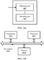
- FIG. 11a and FIG. 11b are schematic structural diagrams of a control information transmission apparatus according to an embodiment of the present invention.
- the control information transmission apparatus in this embodiment of the present invention is applied to a network device, and may be more specifically a transmission/reception point, for example, a base station; or may be a device that can implement corresponding functions of the network device described in the foregoing methods.
- the apparatus may include a determining unit 101, a coding unit 102, and a mapping unit 103.
- the determining unit 101 may be configured to perform a determining action performed by the network device described in the method in FIG. 3 .
- the coding unit 102 may be configured to perform a coding action performed by the network device described in the method in FIG. 3 .
- the mapping unit 103 may be configured to perform, on a codeword that is coded by the coding unit 102, corresponding processing described in the foregoing method.
- the mapping unit 103 may be implemented by a transceiver 1001 in FIG. 11b .
- the determining unit 101 and the coding unit 102 may be implemented by a processor 1002, or the determining unit 101 and the coding unit 102 may be implemented by a processor 1002 and a memory 1003.
- the determining unit 101 is configured to determine N pieces of to-be-jointly-coded downlink control information DCI, where N is an integer greater than or equal to 2.
- the coding unit 102 is configured to jointly code the N pieces of DCI in a polar coding manner, to obtain one codeword.
- the mapping unit 103 is configured to map the codeword to a time-frequency resource of a downlink control channel for sending.
- the coding unit 102 jointly codes the N pieces of DCI in the polar coding manner, to obtain one codeword specifically includes: cascading the N pieces of DCI in a preset order, and jointly coding the cascaded N pieces of DCI in the polar coding manner, to obtain one codeword.
- the preset order includes at least one of the following orders:
- the determining unit 101 determines the N pieces of to-be-jointly-coded downlink control information DCI specifically includes:
- a time-frequency resource of the downlink control channel in a time interval carries one codeword; or a time-frequency resource of the downlink control channel in one time interval carries M codewords, and user equipment of DCI included in any one of the M codewords is in same or similar channel conditions, where M is an integer greater than or equal to 2.
- the apparatus may include the transceiver 1001 and the processor 1002.
- the processor 1002 is configured to control an operation of the apparatus, including: performing time-frequency resource mapping (including receiving and/or sending) for DCI by using the transceiver 1001.
- the apparatus may include the memory 1003, and the memory 1003 may include a read-only memory and a random access memory, and is configured to provide an instruction and data for the processor 1002.
- the memory 1003 may be integrated into the processor 1002, or may be independent of the processor 1002.
- a part of the memory 1003 may further include a non-volatile random access memory (NVRAM).
- Components of the apparatus are coupled together by using a bus system.
- a bus system 1009 includes a power bus, a control bus, and a status signal bus. However, for clear description, various types of buses in the figure are marked as the bus system 1009.
- a process disclosed on a network device side in FIG. 3 in the embodiments of this application may be applied to the processor 3002, or may be implemented by the processor 3002.
- steps of a process implemented by the apparatus can be implemented by using a hardware integrated logical circuit in the processor 3002, or by using instructions in a form of software.
- the processor 3002 may be a general purpose processor, a digital signal processor, an application-specific integrated circuit, a field programmable gate array or another programmable logic device, a discrete gate or a transistor logic device, or a discrete hardware component, and may implement or execute the methods, steps, and logical block diagrams disclosed in the embodiments of this application.
- the general purpose processor may be a microprocessor or any conventional processor or the like.
- the steps of the method disclosed with reference to the embodiments of this application may be directly performed by a hardware processor, or may be performed by using a combination of hardware in the processor and a software module.
- the software module may be located in a mature storage medium in the art, such as a random access memory, a flash memory, a read-only memory, a programmable read-only memory, an electrically erasable programmable memory, or a register.
- the storage medium is located in the memory 1003, and the processor 1002 reads information in the memory 1003 and completes the steps in processes in the embodiments of the present invention in combination with hardware of the processor.
- the processor 1002 is configured to determine N pieces of to-be-jointly-coded downlink control information DCI, where N is an integer greater than or equal to 2.
- the processor 1002 is further configured to jointly code the N pieces of DCI in a polar coding manner, to obtain one codeword.
- the transceiver 1001 is configured to map the codeword to a time-frequency resource of a downlink control channel for sending.
- the processor 1002 is further configured to cascade the N pieces of DCI in a preset order, and jointly code the cascaded N pieces of DCI in the polar coding manner, to obtain one codeword.
- the preset order includes at least one of the following orders:
- the processor 1002 is further configured to determine the N pieces of to-be-jointly-coded DCI according to a preset rule, where the preset rule includes at least one of the following rules:
- a time-frequency resource of the downlink control channel in a time interval carries one codeword; or a time-frequency resource of the downlink control channel in one time interval carries M codewords, and user equipment of DCI included in any one of the M codewords is in same or similar channel conditions, where M is an integer greater than or equal to 2.
- the network device may further include a communications interface module, configured to communicate with another base station or network element, for example, a network element in a core network.
- a communications interface module configured to communicate with another base station or network element, for example, a network element in a core network.
- an embodiment of the present invention further provides a control information transmission apparatus.
- the apparatus may be the user equipment described in the foregoing methods, or may be another device that can implement actions of the user equipment in the foregoing methods.
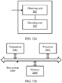
- FIG. 12a and FIG. 12b are schematic structural diagrams of a control information transmission apparatus according to an embodiment of the present invention.
- the apparatus may include an obtaining unit 201 and a decoding unit 202.
- the obtaining unit 201 may be configured to perform an obtaining action performed by the user equipment described in the method in FIG. 3 .
- the decoding unit 202 may be configured to perform a decoding action performed by the user equipment described in the method in FIG. 3 .
- the obtaining unit 201 may be implemented by a transceiver 2001 in FIG. 12b .
- the decoding unit 202 may be implemented by a processor 2001, or implemented by a processor 2002 and a memory 2003.
- the obtaining unit 201 is configured to: when information sent by a network device is received, obtain to-be-decoded information that includes DCI of the user equipment from the information, where the to-be-decoded information carries a codeword obtained by the network device by jointly coding N pieces of DCI in a polar coding manner, and N is an integer greater than or equal to 2.
- the decoding unit 202 is configured to perform sequential polar code decoding on the to-be-decoded information, to obtain the DCI of the user equipment.
- the DCI of the user equipment includes a cyclic redundancy check CRC code formed by performing scrambling by using a preset identifier corresponding to the user equipment.
- That the decoding unit 202 performs sequential polar code decoding on the to-be-decoded information, to obtain the DCI of the user equipment specifically includes: performing sequential polar code decoding on the to-be-decoded information, and each time one piece of DCI is decoded, descrambling, by the user equipment, a CRC in the DCI by using the preset identifier corresponding to the user equipment; checking an information part of the DCI by using a descrambled CRC; and if the check succeeds, determining that the DCI is the DCI of the user equipment.
- the preset identifier corresponding to the user equipment includes a unique identifier pre-allocated to the user equipment, or a group identifier pre-allocated to a group in which the user equipment is located.
- control information transmission apparatus may include the transceiver 2001, the processor 2002, and the memory 2003.
- the processor 2002 is configured to control an operation of the apparatus, including transmitting (including receiving and/or sending) data by using the transceiver 2001.
- the memory 2003 may include a read-only memory and a random access memory, and is configured to provide an instruction and data for the processor 2002.
- a part of the memory 2003 may further include a non-volatile random access memory (NVRAM).
- NVRAM non-volatile random access memory
- Components of the apparatus are coupled together by using a bus system.
- a bus system 2009 includes a power bus, a control bus, and a status signal bus. However, for clear description, various types of buses in the figure are marked as the bus system 2009.
- a process disclosed on a user equipment side in FIG. 3 in the embodiments of this application may be applied to the processor 2002, or may be implemented by the processor 2002.
- steps of a process implemented by the apparatus can be implemented by using a hardware integrated logical circuit in the processor 2002, or by using instructions in a form of software.
- the processor 2002 may be a general purpose processor, a digital signal processor, an application-specific integrated circuit, a field programmable gate array or another programmable logic device, a discrete gate or a transistor logic device, or a discrete hardware component, and may implement or execute the methods, steps, and logical block diagrams disclosed in the embodiments of this application.
- the general purpose processor may be a microprocessor or any conventional processor or the like.
- the steps of the method disclosed with reference to the embodiments of this application may be directly performed by a hardware processor, or may be performed by using a combination of hardware in the processor and a software module.
- the software module may be located in a mature storage medium in the art, such as a random access memory, a flash memory, a read-only memory, a programmable read-only memory, an electrically erasable programmable memory, or a register.
- the storage medium is located in the memory 2003, and the processor 2002 reads information in the memory 2003 and completes the steps in processes in the embodiments of the present invention in combination with hardware of the processor.
- the transceiver 2001 is configured to: when information sent by a network device is received, obtain to-be-decoded information that includes DCI of the user equipment from the information, where the to-be-decoded information carries a codeword obtained by the network device by jointly coding N pieces of DCI in a polar coding manner, and N is an integer greater than or equal to 2.
- the processor 2002 is configured to perform sequential polar code decoding on the to-be-decoded information, to obtain the DCI of the user equipment.
- the DCI of the user equipment includes a cyclic redundancy check CRC code formed by performing scrambling by using a preset identifier corresponding to the user equipment.
- the processor 2002 is further configured to: perform sequential polar code decoding on the to-be-decoded information, and each time one piece of DCI is decoded, descramble, by the user equipment, a CRC in the DCI by using the preset identifier corresponding to the user equipment; check an information part of the DCI by using a descrambled CRC; and if the check succeeds, determine that the DCI is the DCI of the user equipment.
- the preset identifier corresponding to the user equipment includes a unique identifier pre-allocated to the user equipment, or a group identifier pre-allocated to a group in which the user equipment is located.
- the apparatus when the apparatus is user equipment, the apparatus may further include an input device such as a keyboard, an output device such as a display screen, and other structures. Details are not described herein.
- An embodiment of this application further provides a system, including the foregoing apparatus configured to jointly coding a plurality of pieces of DCI and the foregoing apparatus configured to sequentially decode to-be-decoded information.
- the system may be a communications system or another system.
- FIG. 13a and FIG. 13b are schematic structural diagrams of a feedback information transmission apparatus according to an embodiment of the present invention.
- the feedback information transmission apparatus in this embodiment of the present invention is applied to a first device, and the first device may be a network device, and more specifically, may be a transmission/reception pint, for example, a base station.
- the first device may alternatively be user equipment.
- the second device is user equipment.
- the second device is a network device.
- the apparatus may include a determining unit 301, a coding unit 302, and a mapping unit 303.
- the determining unit 301 may be configured to perform a determining action performed by the first device described in the method in FIG. 8 .
- the coding unit 302 may be configured to perform a coding action performed by the first device described in the method in FIG. 8 .
- the mapping unit 303 may be configured to perform, on a codeword that is coded by the coding unit 302, corresponding processing performed by the first device described in the method in FIG. 8 .
- the mapping unit 303 may be implemented by a transceiver 3001 in FIG. 13b .
- the determining unit 301 and the coding unit 302 may be implemented by a processor 3002, or the determining unit 301 and the coding unit 302 may be implemented by a processor 3002 and a memory 3003.
- the determining unit 301 is configured to determine Q pieces of feedback information, where the Q pieces of feedback information are feedbacks for received data carried by P data transmission units, Q is an integer greater than or equal to 2, P is greater than or equal to Q, and P is an integer.
- the coding unit 302 is configured to jointly code the Q pieces of feedback information in a polar coding manner, to obtain one codeword.
- the mapping unit 303 is configured to map the codeword to a corresponding time-frequency resource for sending.
- the data carried by the P data transmission units is data sent by at least one user equipment to the network device, and the at least one user equipment is in same channel conditions.
- the data carried by the P data transmission units is data sent by a network device to the user equipment.
- the coding unit 302 jointly codes the Q pieces of feedback information in the polar coding manner, to obtain one codeword specifically includes: dividing the Q pieces of feedback information into R information segments by using K pieces of feedback information as a basic unit, where K is an integer greater than or equal to 2, and K ⁇ R is greater than or equal to Q; and adding a CRC after each information segment, and jointly coding R information segments to which the CRC is added, to obtain one codeword.
- the data transmission unit includes a code block CB, and one piece of feedback information corresponds to at least one CB; or the data transmission unit includes a component carrier CC, and one piece of feedback information corresponds to one CC.
- the apparatus may include the transceiver 3001 and the processor 3002.
- the processor 3002 is configured to control an operation of the apparatus, including: performing time-frequency resource mapping (including receiving and/or sending) for feedback information by using the transceiver 3001.
- the apparatus may include the memory 3003, and the memory 3003 may include a read-only memory and a random access memory, and is configured to provide an instruction and data for the processor 3002.
- the memory 3003 may be integrated into the processor 3002, or may be independent of the processor 3002.
- a part of the memory 3003 may further include a non-volatile random access memory (NVRAM).
- Components of the apparatus are coupled together by using a bus system.
- a bus system 3009 includes a power bus, a control bus, and a status signal bus. However, for clear description, various types of buses in the figure are marked as the bus system 3009.
- a process disclosed on a first device side in FIG. 8 in the embodiments of this application may be applied to the processor 3002, or may be implemented by the processor 3002.
- steps of a process implemented by the apparatus can be implemented by using a hardware integrated logical circuit in the processor 3002, or by using instructions in a form of software.
- the processor 3002 may be a general purpose processor, a digital signal processor, an application-specific integrated circuit, a field programmable gate array or another programmable logic device, a discrete gate or a transistor logic device, or a discrete hardware component, and may implement or execute the methods, steps, and logical block diagrams disclosed in the embodiments of this application.
- the general purpose processor may be a microprocessor or any conventional processor or the like.
- the steps of the method disclosed with reference to the embodiments of this application may be directly performed by a hardware processor, or may be performed by using a combination of hardware in the processor and a software module.
- the software module may be located in a mature storage medium in the art, such as a random access memory, a flash memory, a read-only memory, a programmable read-only memory, an electrically erasable programmable memory, or a register.
- the storage medium is located in the memory 3003, and the processor 3002 reads information in the memory 3003 and completes the steps in processes in the embodiments of the present invention in combination with hardware of the processor.
- the processor 3002 is configured to determine Q pieces of feedback information, where the Q pieces of feedback information are feedbacks for received data carried by P data transmission units, Q is an integer greater than or equal to 2, P is greater than or equal to Q, and P is an integer.
- the processor 3002 is further configured to jointly code the Q pieces of feedback information in a polar coding manner, to obtain one codeword.
- the transceiver 3001 is configured to map the codeword to a corresponding time-frequency resource for sending.
- the data carried by the P data transmission units is data sent by at least one user equipment to the network device, and the at least one user equipment is in same channel conditions.
- the data carried by the P data transmission units is data sent by a network device to the user equipment.
- the processor 3002 is further configured to: divide the Q pieces of feedback information into R information segments by using K pieces of feedback information as a basic unit, where K is an integer greater than or equal to 2, and K ⁇ R is greater than or equal to Q; and add a CRC after each information segment, and jointly code R information segments to which the CRC is added, to obtain one codeword.
- the data transmission unit includes a code block CB, and one piece of feedback information corresponds to at least one CB; or the data transmission unit includes a component carrier CC, and one piece of feedback information corresponds to one CC.
- the network device may further include a communications interface module, configured to communicate with another base station or network element, for example, a network element in a core network.
- the apparatus may further include an input device such as a keyboard, an output device such as a display screen, and other structures.
- an input device such as a keyboard
- an output device such as a display screen
- an embodiment of the present invention further provides a feedback information transmission apparatus.
- the apparatus may be the second device described in the foregoing methods, or may be another device that can implement actions of the second device in the foregoing methods.
- the second device may be a network device, and more specifically, may be a transmission/reception point, for example, a base station.
- the second device may alternatively be user equipment.
- the first device is user equipment.
- the second device is user equipment
- the first device is a network device.
- FIG. 14a and FIG. 14b are schematic structural diagrams of a feedback information transmission apparatus according to an embodiment of the present invention.
- the apparatus may include an obtaining unit 401 and a decoding unit 402.
- the obtaining unit 401 may be configured to perform an obtaining action performed by the second device described in the method in FIG. 8 .
- the decoding unit 402 may be configured to perform a decoding action performed by the second device described in the method in FIG. 8 .
- the obtaining unit 401 may be implemented by a transceiver 4001 in FIG. 14b .
- the decoding unit 402 may be implemented by a processor 4002, or implemented by a processor 4002 and a memory 4003.
- the obtaining unit 401 is configured to: when information fed back by a first device is received, obtain to-be-decoded information from the information, where the to-be-decoded information carries a codeword obtained by the first device by jointly coding Q pieces of feedback information in a polar coding manner, and Q is an integer greater than or equal to 2.
- the decoding unit 402 is configured to perform sequential polar code decoding on the to-be-decoded information, to obtain the Q pieces of feedback information.
- the codeword includes R information segments, the R information segments are obtained by dividing the Q pieces of feedback information by using K pieces of feedback information as a basic unit, and each information segment includes one CRC.
- That the decoding unit 402 performs sequential polar code decoding on the to-be-decoded information specifically includes: performing sequential polar code decoding on the to-be-decoded information in a form of consecutive information segments, and each time one information segment is decoded, checking the information segment by using a CRC of the information segment.
- the feedback information transmission apparatus may include the transceiver 4001, the processor 4002, and the memory 4003.
- the processor 4002 is configured to control an operation of the apparatus, including transmitting (including receiving and/or sending) data by using the transceiver 4001.
- the memory 4003 may include a read-only memory and a random access memory, and is configured to provide an instruction and data for the processor 4002.
- a part of the memory 4003 may further include a non-volatile random access memory (NVRAM).
- NVRAM non-volatile random access memory
- Components of the apparatus are coupled together by using a bus system.
- a bus system 4009 includes a power bus, a control bus, and a status signal bus. However, for clear description, various types of buses in the figure are marked as the bus system 4009.
- a process disclosed on a second device side in FIG. 8 in the embodiments of this application may be applied to the processor 4002, or may be implemented by the processor 4002.
- steps of a process implemented by the apparatus can be implemented by using a hardware integrated logical circuit in the processor 4002, or by using instructions in a form of software.
- the processor 4002 may be a general purpose processor, a digital signal processor, an application-specific integrated circuit, a field programmable gate array or another programmable logic device, a discrete gate or a transistor logic device, or a discrete hardware component, and may implement or execute the methods, steps, and logical block diagrams disclosed in the embodiments of this application.
- the general purpose processor may be a microprocessor or any conventional processor or the like.
- the steps of the method disclosed with reference to the embodiments of this application may be directly performed by a hardware processor, or may be performed by using a combination of hardware in the processor and a software module.
- the software module may be located in a mature storage medium in the art, such as a random access memory, a flash memory, a read-only memory, a programmable read-only memory, an electrically erasable programmable memory, or a register.
- the storage medium is located in the memory 4003, and the processor 4002 reads information in the memory 4003 and completes the steps in processes in the embodiments of the present invention in combination with hardware of the processor.
- the transceiver 4001 is configured to: when information fed back by a first device is received, obtain to-be-decoded information from the information, where the to-be-decoded information carries a codeword obtained by the first device by jointly coding Q pieces of feedback information in a polar coding manner, and Q is an integer greater than or equal to 2.
- the processor 4002 is configured to perform sequential polar code decoding on the to-be-decoded information, to obtain the Q pieces of feedback information.
- the codeword includes R information segments, the R information segments are obtained by dividing the Q pieces of feedback information by using K pieces of feedback information as a basic unit, and each information segment includes one CRC.
- the processor 4002 is further configured to: perform sequential polar code decoding on the to-be-decoded information in a form of consecutive information segments, and each time one information segment is decoded, check the information segment by using a CRC of the information segment.
- the apparatus when the apparatus is user equipment, the apparatus may further include an input device such as a keyboard, an output device such as a display screen, and other structures. Details are not described herein.
- the apparatus may further include a communications interface module, configured to communicate with another base station or network element, for example, a network element in a core network.
- a communications interface module configured to communicate with another base station or network element, for example, a network element in a core network.
- An embodiment of this application further provides a system, including the foregoing apparatus configured to jointly coding a plurality of pieces of feedback information and the foregoing apparatus configured to sequentially decode to-be-decoded information.
- the system may be a communications system or another system.
- system and “network” may be used interchangeably in this specification.
- network may be used interchangeably in this specification.
- the term “and/or” in this specification describes only an association relationship for describing associated objects and represents that three relationships may exist. For example, A and/or B may represent the following three cases: Only A exists, both A and B exist, and only B exists.
- the character “/” in this specification generally indicates an “or” relationship between the associated objects.
- B corresponding to A indicates that B is associated with A, and B may be determined based on A.
- determining B based on A does not mean that B is determined based on A only, and B may also be determined based on A and/or other information.
- "at least one of A, B, and C” represents selecting at least one from a set (A, B, and C), for example, A; B; C; A and B; A and C; B and C; or A, B, and C. Descriptions such as "a first A” and "a second A” in the embodiments of this application are merely used to distinguish between a plurality of As, and are not used to represent other meanings.
- the disclosed system, apparatus, and method may be implemented in other manners.
- the described apparatus embodiment is merely an example.
- the unit division is merely logical function division and may be other division in actual implementation.
- a plurality of units or components may be combined or integrated into another system, or some features may be ignored or not performed.
- the displayed or discussed mutual couplings or direct couplings or communication connections may be implemented through indirect couplings or communication connections between some transceivers, apparatuses, or units, or electrical connections, mechanical connections, or connections in other forms.
- the units described as separate parts may or may not be physically separate, and parts displayed as units may or may not be physical units, may be located in one position, or may be distributed on a plurality of network units. Some or all of the units may be selected based on actual requirements to achieve the objectives of the solutions of the embodiments of the present invention.
- functional units in the embodiments of the present invention may be integrated into one processor, or each of the units may exist alone physically, or two or more units are integrated into one unit.
- the integrated unit may be implemented in a form of hardware, or may be implemented in a form of a software functional unit.
- the present invention may be implemented by hardware, firmware, or a combination thereof.
- the foregoing functions may be stored in a computer-readable medium or transmitted as one or more instructions or code in the computer-readable medium.
- the computer-readable medium includes a computer storage medium and a communications medium, and the communications medium includes any medium that enables a computer program to be transmitted from one place to another.
- the storage medium may be any available medium accessible to a computer.
- the computer-readable medium may include a RAM, a ROM, an EEPROM, a CD-ROM, or another optical disc storage or a disk storage medium, or another magnetic storage device, or any other medium that can carry or store expected program code in a form of an instruction or a data structure and can be accessed by a computer.
- any connection may be appropriately defined as a computer-readable medium.
- the coaxial cable, optical fiber/cable, twisted pair, DSL or wireless technologies such as infrared ray, and radio and microwave
- the coaxial cable, optical fiber/cable, twisted pair, DSL or wireless technologies such as infrared ray, and radio and microwave are included in fixation of a medium to which they belong.
- a disk (Disk) and a disc (disc) used in the present invention include a compact disc (CD), a laser disc, an optical disc, a digital versatile disc (DVD), a floppy disk and a Blu-ray disc, and the disk generally copies data by using a magnetic means, and the disc copies data optically by using a laser means.
- CD compact disc
- DVD digital versatile disc
- floppy disk a floppy disk
- Blu-ray disc Blu-ray disc
- the embodiments of the present invention may be provided as a method, a system, or a computer program product. Therefore, the embodiments of the present invention may use a form of hardware only embodiments, software only embodiments, or embodiments with a combination of software and hardware. Moreover, the embodiments of the present invention may use a form of a computer program product that is implemented on one or more computer-usable storage media (including but not limited to a disk memory, a CD-ROM, an optical memory, and the like) that include computer-usable program code.
- computer-usable storage media including but not limited to a disk memory, a CD-ROM, an optical memory, and the like
- These computer program instructions may be provided for a general-purpose computer, a dedicated computer, an embedded processor, or a processor of any other programmable data processing device, so that the instructions executed by the computer or the processor of any other programmable data processing device may implement a specific function in one or more processes in the flowcharts and/or in one or more blocks in the block diagrams.
- These computer program instructions may also be stored in a computer readable memory that can instruct the computer or any other programmable data processing device to work in a specific manner, so that the instructions stored in the computer readable memory generate an artifact that includes an instruction apparatus.
- the instruction apparatus implements a specific function in one or more processes in the flowcharts and/or in one or more blocks in the block diagrams.
- These computer program instructions may also be loaded onto a computer or another programmable data processing device, so that a series of operations and steps are performed on the computer or the another programmable device, thereby generating computer-implemented processing. Therefore, the instructions executed on the computer or the another programmable device provide steps for implementing a specific function in one or more processes in the flowcharts and/or in one or more blocks in the block diagrams.
- the program may be stored in a computer readable storage medium. When the program runs, the processes of the methods in the embodiments are performed.
- the foregoing storage medium includes: any medium that can store program code, such as a ROM, a random access memory RAM, a magnetic disk, or an optical disc.
Abstract
Description
- The present invention relates to the field of communications technologies, and in particular, to a control information transmission method and apparatus.
- In a long term evolution (Long Term Evolution, LTE) system, control information mainly includes downlink control information (downlink control information, DCI) and uplink control information (uplink control information, UCI). The control information carries a function of scheduling an entire communications system, and reliability and coverage of the control information directly affect reliability and coverage of the entire system.
- Compared with data information, the control information usually has a shorter length. For example, a length of DCI in the LTE is usually ten-plus to seventy-plus bits. The DCI also has a relatively short code length after being coded. For example, in the LTE, coded DCI has four lengths: 72 bits, 144 bits, 288 bits, and 576 bits. In other words, a maximum length is 576 bits.
- In the LTE system, after coding and modulating the DCI, a base station maps the DCI to a downlink control channel and sends the downlink control channel to user equipment (User Equipment, UE). The downlink control channel is usually located in first one to three orthogonal frequency division multiplexing (Orthogonal Frequency Division Multiplexing, OFDM) symbols of each sub frame.
- As shown in
FIG. 1 , in the LTE system, a plurality of pieces of DCI delivered by the base station in a same subframe are modulated and mapped after being separately coded. A code rate of the DCI is determined by the base station based on a channel condition of a user, and there are four aggregation levels of time-frequency resources used for carrying a physical downlink control channel (Physical Downlink Control Channel, PDCCH). The four aggregation levels respectively correspond to a code length of 72 bits, a code length of 144 bits, a code length of 288 bits, and a code length of 576 bits. Given a length of the DCI, the base station may send the DCI to UE in a better channel condition by using a PDCCH corresponding to a lower aggregation level (for example, a code length is 72 bits or 144 bits), and send the DCI to UE in a poorer channel condition by using a PDCCH corresponding to a higher aggregation level (for example, a code length is 288 bits or 576 bits). - Embodiments of the present invention provide a control information transmission method and apparatus, so that not only a relatively high coding gain can be obtained, but a relatively low average processing latency on a decoder side can be obtained.
- A first aspect provides a control information transmission method, and the control information transmission method may be performed by a network device. Optionally, the network device determines N pieces of to-be-jointly-coded downlink control information DCI, where N is an integer greater than or equal to 2. The network device cascades and sorts the N pieces of DCI, and jointly codes the cascaded and sorted N pieces of DCI in a polar polar coding manner, to obtain one codeword.
- The network device maps the codeword to a time-frequency resource of a downlink control channel for sending. Optionally, the network device may map the codeword to the time-frequency resource of the downlink control channel according to a preset channel resource mapping rule. When the N pieces of DCI are jointly coded in this manner, a relatively high coding gain can be obtained, and sequential polar code decoding is performed on a decoder side, so that a relatively low average processing latency on the decoder side is obtained.
- In a possible design, each of the N pieces of DCI includes a cyclic redundancy check (Cyclic Redundancy Check, CRC) code, and the CRC may be formed by performing scrambling by using a preset identifier corresponding to user equipment of the DCI.
- In a possible design, when jointly coding the N pieces of DCI in the polar polar coding manner, the network device first cascades the N pieces of DCI in a preset order, and then jointly codes the cascaded N pieces of DCI in the polar polar coding manner, to obtain one codeword.
- In a possible design, the preset order may include at least one of the following orders: DCI of user equipment with a high priority ranks higher than DCI of user equipment with a low priority; DCI of user equipment in a good channel condition ranks higher than DCI of user equipment in a poor channel condition; and DCI of latency-sensitive user equipment ranks higher than DCI of latency-insensitive user equipment.
- In a possible design, a manner in which the network device determines the N pieces of to-be-jointly-coded DCI may be: The network device determines the N pieces of to-be-jointly-coded DCI according to a preset rule, where the preset rule may be at least one of the following rules: one rule may be that user equipments of the N pieces of DCI are in same or similar channel conditions, in other words, DCI of user equipments that are in same or similar channel conditions is coded together into one codeword, and being in similar channel conditions may be that a difference between channel parameters of the user equipments of the N pieces of DCI is within a specific threshold; and another rule may be that functions indicated by information carried in the N pieces of DCI are the same, for example, all the functions indicated by the information carried in the N pieces of DCI are uplink data channel scheduling.
- In a possible design, a time-frequency resource of the downlink control channel in one time interval carries one codeword, in other words, an entire downlink control channel area in one time interval is used to carry one codeword.
- Alternatively, a time-frequency resource of the downlink control channel in one time interval carries M codewords, and user equipment of DCI included in any one of the M codewords is in same or similar channel conditions, where M is an integer greater than or equal to 2.
- A second aspect provides a control information transmission method, and the control information transmission method may be performed by user equipment. Optionally, when receiving information sent by a network device, the user equipment obtains to-be-decoded information that includes DCI of the user equipment from the information. Optionally, the user equipment may obtain the to-be-decoded information that includes the DCI of the user equipment from the information according to a preset channel resource mapping rule. The to-be-decoded information carries a codeword obtained by the network device by jointly coding N pieces of DCI in a polar polar coding manner, where N is an integer greater than or equal to 2.
- The user equipment sequentially decodes the to-be-decoded information, to obtain the DCI of the user equipment from the to-be-decoded information. Further optionally, after obtaining the DCI of the user equipment through decoding, the user equipment stops decoding, and performs a corresponding operation based on the DCI of the user equipment.
- In a possible design, the DCI of the user equipment includes a cyclic redundancy check (Cyclic Redundancy Check, CRC) code formed by performing scrambling by using a preset identifier corresponding to the user equipment, and when the user equipment sequentially decodes the to-be-decoded information, each time one piece of DCI is decoded, the user equipment descrambles a CRC in the DCI by using the preset identifier corresponding to the user equipment.
- Then, the user equipment checks an information part of the DCI by using a descrambled CRC, to be specific, determines whether the DCI is the DCI of the user equipment. If the check succeeds, the DCI is the DCI of the user equipment.
- In a possible design, the preset identifier corresponding to the user equipment includes a unique identifier pre-allocated to the user equipment, for example, a unique identifier is allocated to the user equipment based on a function of the DCI. Alternatively, the preset identifier corresponding to the user equipment is a group identifier that is pre-allocated to a group in which the user equipment is located.
- A third aspect provides a feedback information transmission method, the feedback information transmission method is performed by a first device, and the first device may be user equipment or a network device. Optionally, the first device determines Q pieces of feedback information, where the Q pieces of feedback information are feedbacks for data that is carried by P data transmission units and received by the first device, Q is an integer greater than or equal to 2, P is greater than or equal to Q, and P is an integer.
- The first device jointly codes the Q pieces of feedback information in a polar polar coding manner, to obtain one codeword, and then maps the codeword to a corresponding time-frequency resource for sending.
- In a possible design, if the first device is a network device, the data carried by the P data transmission units is data sent by at least one user equipment to the network device, and the at least one user equipment is in same or similar channel conditions. In other words, the network device codes, into one codeword for feedback, feedback information of the at least one user equipment in same or similar channel conditions for data sent by the network device.
- If the first device is user equipment, the data carried by the P data transmission units is data sent by a network device to the user equipment.
- In a possible design, a coding manner in which the first device jointly codes the Q pieces of feedback information in the polar polar coding manner may be: The first device divides the Q pieces of feedback information into R information segments by using K pieces of feedback information as a basic unit, where K is an integer greater than or equal to 2, and K×R is greater than or equal to Q.
- The first device adds a CRC after each information segment, and jointly codes R information segments to which the CRC is added, to obtain one codeword.
- In a possible design, the data transmission unit may be a basic unit for transmitting data. For example, the data transmission unit may include a code block (code block, CB), and one piece of feedback information may correspond to at least one CB. For example, one piece of feedback information may be used to feed back data transmitted by two consecutive CBs.
- Alternatively, the data transmission unit may be a basic carrying unit that carries transmitted data. For example, the data transmission unit may include a component carrier (component carrier, CC), the CC is used to carry a transmission block (transmission block, TB), and one piece of feedback information corresponds to one CC.
- A fourth aspect provides a feedback information transmission method, and the feedback information transmission method is performed by a second device. The second device may be user equipment or a network device. If a first device is user equipment, the second device is a network device, and if the first device is a network device, the second device is user equipment.
- Optionally, when the second device receives information fed back by the first device, the second device obtains to-be-decoded information from the information, where the to-be-decoded information carries a codeword obtained by the first device by jointly coding Q pieces of feedback information in a polar polar coding manner, and Q is an integer greater than or equal to 2.
- The second device performs sequential polar code decoding on the to-be-decoded information, to obtain the Q pieces of feedback information. Optionally, when the second device decodes feedback information indicating that retransmission needs to be performed, the second device retransmits corresponding data.
- In a possible design, the codeword carried in the to-be-decoded information includes R information segments, the R information segments are obtained by dividing the Q pieces of feedback information by using K pieces of feedback information as a basic unit, and each information segment includes one CRC.
- When sequentially decoding the to-be-decoded information, the second device performs sequential polar code decoding on the to-be-decoded information in a form of consecutive information segments, and each time one information segment is decoded, the network device checks the information segment by using a CRC of the information segment. If the check succeeds, the second device determines, based on feedback information of the information segment, whether to retransmit data.
- A fifth aspect provides a control information transmission apparatus, applied to a network device, and the control information transmission apparatus includes a determining unit, a coding unit, and a mapping unit. The determining unit is configured to determine N pieces of to-be-jointly-coded downlink control information DCI, where N is an integer greater than or equal to 2. The coding unit is configured to jointly code the N pieces of DCI in a polar coding manner, to obtain one codeword. The mapping unit is configured to map the codeword to a time-frequency resource of a downlink control channel for sending. Optionally, the mapping unit may map, according to a preset channel resource mapping rule, the codeword to the time-frequency resource of the downlink control channel for sending.
- A sixth aspect provides a control information transmission apparatus, applied to user equipment, and the control information transmission apparatus includes an obtaining unit and a decoding unit. The obtaining unit is configured to: when information sent by a network device is received, obtain to-be-decoded information that includes DCI of the user equipment from the information, where the to-be-decoded information carries a codeword obtained by the network device by jointly coding N pieces of DCI in a polar coding manner, and N is an integer greater than or equal to 2. The decoding unit is configured to perform sequential polar code decoding on the to-be-decoded information, to obtain the DCI of the user equipment.
- A seventh aspect provides a feedback information transmission apparatus, applied to a first device, and the feedback information transmission apparatus includes a determining unit, a coding unit, and a mapping unit. The determining unit is configured to determine Q pieces of feedback information, where the Q pieces of feedback information are feedbacks for received data carried by P data transmission units, Q is an integer greater than or equal to 2, P is greater than or equal to Q, and P is an integer. The coding unit is configured to jointly code the Q pieces of feedback information in a polar coding manner, to obtain one codeword. The mapping unit is configured to map the codeword to a corresponding time-frequency resource for sending.
- An eighth aspect provides a feedback information transmission apparatus, applied to a second device, and the feedback information transmission apparatus includes an obtaining unit and a decoding unit. The obtaining unit is configured to: when information fed back by a first device is received, obtain to-be-decoded information from the information, where the to-be-decoded information carries a codeword obtained by the first device by jointly coding Q pieces of feedback information in a polar coding manner, and Q is an integer greater than or equal to 2. The decoding unit is configured to perform sequential polar code decoding on the to-be-decoded information, to obtain the Q pieces of feedback information.
- A ninth aspect provides a control information transmission apparatus, applied to a network device, and the control information transmission apparatus includes a transceiver, a processor, and a memory. The control information transmission apparatus is a specific structure that carries function modules in the fifth aspect.
- The memory is configured to store a computer program instruction.
- The processor is coupled to the memory, and is configured to read the computer program instruction stored in the memory and perform the method provided in the first aspect.
- A tenth aspect provides a control information transmission apparatus, applied to user equipment, and the control information transmission apparatus includes a transceiver, a processor, and a memory. The control information transmission apparatus is a specific structure that carries function modules in the sixth aspect.
- The memory is configured to store a computer program instruction.
- The processor is coupled to the memory, and is configured to read the computer program instruction stored in the memory and perform the method provided in the second aspect.
- An eleventh aspect provides a feedback information transmission apparatus, applied to a first device, and the feedback information transmission apparatus includes a transceiver, a processor, and a memory. The feedback information transmission apparatus is a specific structure that carries function modules in the seventh aspect.
- The memory is configured to store a computer program instruction.
- The processor is coupled to the memory, and is configured to read the computer program instruction stored in the memory and perform the method provided in the third aspect.
- A twelfth aspect provides a feedback information transmission apparatus, applied to a second device, and the feedback information transmission apparatus includes a transceiver, a processor, and a memory. The feedback information transmission apparatus is a specific structure that carries function modules in the eighth aspect.
- The memory is configured to store a computer program instruction.
- The processor is coupled to the memory, and is configured to read the computer program instruction stored in the memory and perform the method provided in the fourth aspect.
- In the embodiments of the present invention, when transmitting DCI, the network device determines the N pieces of to-be-jointly-coded DCI, and jointly codes the N pieces of DCI in the polar coding manner, to obtain one codeword. In this joint coding manner, a relatively high channel coding gain can be obtained, and DCI transmission reliability can be improved. In addition, because the polar coding manner is used, the user equipment can quickly obtain the DCI of the user equipment through sequential decoding, and perform a corresponding operation. In this way, a relatively low average processing latency of the user equipment is obtained.
- To describe the technical solutions in the embodiments of the present invention more clearly, the following briefly describes the accompanying drawings required for the embodiments.
-
FIG. 1 shows a coding manner of DCI in the prior art; -
FIG. 2 is a schematic diagram of an LTE/NR system architecture according to an embodiment of the present invention; -
FIG. 3 is an interaction diagram of a control information transmission method according to an embodiment of the present invention; -
FIG. 4 is a schematic diagram of joint coding of a plurality of pieces of DCI according to an embodiment of the present invention; -
FIG. 5 is a schematic diagram of internal scrambling of DCI according to an embodiment of the present invention; -
FIG. 6 is a schematic diagram of DCI coding according to an embodiment of the present invention; -
FIG. 7 is a schematic diagram of another DCI coding according to an embodiment of the present invention; -
FIG. 8 is an interaction diagram of a feedback information transmission method according to an embodiment of the present invention; -
FIG. 9 is a schematic diagram of joint coding for CB-level feedbacks according to an embodiment of the present invention; -
FIG. 10 is a schematic diagram of joint coding for CC-level feedbacks according to an embodiment of the present invention; -
FIG. 11a is a schematic structural diagram of a control information transmission apparatus according to an embodiment of the present invention; -
FIG. 11b is a schematic structural diagram of another control information transmission apparatus according to an embodiment of the present invention; -
FIG. 12a is a schematic structural diagram of a control information transmission apparatus according to an embodiment of the present invention; -
FIG. 12b is a schematic structural diagram of another control information transmission apparatus according to an embodiment of the present invention; -
FIG. 13a is a schematic structural diagram of a feedback information transmission apparatus according to an embodiment of the present invention; -
FIG. 13b is a schematic structural diagram of another feedback information transmission apparatus according to an embodiment of the present invention; -
FIG. 14a is a schematic structural diagram of a feedback information transmission apparatus according to an embodiment of the present invention; and -
FIG. 14b is a schematic structural diagram of another feedback information transmission apparatus according to an embodiment of the present invention. - The following describes the embodiments of the present invention with reference to the accompanying drawings.
- A control information transmission method in the embodiments of the present invention may be applied to DCI transmission in 5th generation (the 5th Generation, 5G) mobile communications New Radio (New Radio, NR).
- A feedback information transmission method in the embodiments of the present invention may be applied to acknowledgement (Acknowledgement, ACK)/negative acknowledgement (Negative Acknowledgement, NACK) feedback information transmission in the 5G New Radio.
- A network device in the embodiments of the present invention is mainly responsible for functions on an air interface side such as radio resource management, quality of service (QoS, Quality of Service) management, and data compression and encryption, for example, a network device (base station) in an LTE system. User equipment in the embodiments of the present invention is a device that accesses a network side by using a network device, for example, a handheld terminal or a notebook computer.
- A time interval in the embodiments of the present invention is a time unit in a time division multiplexing system, for example, a subframe in the LTE system, and a length of one subframe in the LTE system is 1 ms.
- In the embodiments of the present invention, that a plurality of user equipments are in similar channel conditions may be that a difference between channel parameters of the plurality of user equipments is within a specific threshold.
-
FIG. 1 shows a system architecture of an LTE system and a 5G system according to an embodiment of the present invention. Each network element and each interface are described as follows:
Mobility management entity (MME, Mobility Management Entity)/serving gateway (S-GW, Serving Gateway): The MME is a key control node in 3rd Generation Partnership Project (3GPP, 3rd Generation Partnership Project) LTE, is a core network element, and is mainly responsible for a signaling processing part, namely, a control plane function, including functions such as access control, mobility management, attachment and detachment, a session management function, and gateway selection. The S-GW is an important network element in a core network in 3GPP LTE, and is mainly responsible for a user plane function of forwarding user data, to be specific, routing and forwarding a packet under control of the MME. - Evolved NodeB (Evolved NodeB, eNB)/transmission/reception node (transmission/reception point, TRP): The eNB is a network device in the LTE system, and the TRP is a network device in the 5G system, and is mainly responsible for functions on an air interface side such as radio resource management, quality of service (QoS, Quality of Service) management, and data compression and encryption. On a core network side, the eNB is mainly responsible for forwarding control plane signaling to the MME and forwarding user plane service data to the S-GW.
- UE: The UE is a device that accesses a network side by using an eNB in LTE. For example, the UE may be a handheld terminal, a notebook computer, or another device that can access a network.
- S1 interface: The S1 interface is a standard interface between the eNB and a core network. The eNB is connected to the MME by using an S1-MME interface, and is configured to control signaling transmission. The eNB is connected to the S-GW by using an S1-U interface, and is configured to transmit user data. The S1-MME interface and the S1-U interface are collectively referred to as the S1 interface.
- X2 interface: The X2 interface is a standard interface between eNBs, configured to implement interworking between network devices.
- Uu interface: The Uu interface is a wireless interface between UE and a network device. The UE accesses the LTE network by using the Uu interface.
- A control information transmission method in the embodiments of the present invention may be applied to control information transmission between a base station and UE in
FIG. 2 . In an LTE system, control information mainly includes downlink control information (Downlink control information, DCI) and uplink control information (Uplink control information, UCI). - The DCI is used to transmit uplink/downlink scheduling information and related common control information, and is divided into a plurality of formats and carries different functions. Main formats are listed in the following table:
DCI format Function 0 Uplink data channel scheduling 1 Downlink single-codeword data channel scheduling 1a Compact downlink single-codeword data channel scheduling 1b Precoded compact downlink single-codeword data channel scheduling 1c More compact downlink single-codeword data channel scheduling 1d Compact downlink single-codeword data channel scheduling with precoding and power offset information 2 Downlink multi-codeword data channel scheduling in closed-loop spatial multiplexing 2a Downlink multi-codeword data channel scheduling in open-loop spatial multiplexing 3 Power control information transmission on an uplink control channel and a data channel, where power control information is indicated by 2 bits 3a Power control information transmission on an uplink control channel and a data channel, where power control information is indicated by 2 bits - After coding and modulating DCI, the base station maps the DCI to a downlink control channel (usually located in first one to three OFDM symbols of each subframe) to send the DCI to the user equipment. In the LTE system, a plurality of pieces of DCI delivered by the base station in a same subframe are modulated and mapped after being separately coded. A specific modulation manner may be shown in
FIG. 1 . - A code rate of the DCI is determined by the base station based on a channel condition of the UE. In the LTE system, there are four aggregation levels of time-frequency resources used for carrying a PDCCH, and the four aggregation levels respectively correspond to a code length of 72 bits, a code length of 144 bits, a code length of 288 bits, and a code length of 576 bits.
- Given a length of the DCI, the base station may send the DCI to UE in a better channel condition through a PDCCH corresponding to a lower aggregation level (for example, a code length is 72 bits or 144 bits), and send the DCI to UE in a poorer channel condition through a PDCCH corresponding to a higher aggregation level (for example, a code length is 288 bits or 576 bits).
- However, a coding gain of channel coding increases as a code length increases, and in such a control information coding manner using a short code length in an existing LTE system, a very high coding gain cannot be obtained.
- In the embodiments of the present invention, to resolve the foregoing problem of the coding gain, a plurality of pieces of DCI s are jointly coded into a long code, to obtain a relatively high coding gain. However, if a coding manner such as a Turbo or low-density parity-check code (Low Density Parity Check Code, LDPC) is used, the UE at a receive end needs to decode the entire long code, and can obtain, only when completing the decoding, a part that is of the long code and that belongs to the UE. In comparison with coding the DCI by using a short code, in such a joint coding and decoding solution using a long code, a processing latency of the UE is increased.
- To resolve the foregoing problem of the processing latency, in the embodiments of the present invention, further, a plurality of pieces of DCI are jointly coded in a polar coding manner. For example, the plurality of pieces of DCI are cascaded and sorted in a preset order, and then the cascaded and sorted plurality of pieces of DCI are jointly coded in the polar coding manner, to form one codeword, and further, the codeword is modulated and a time-frequency resource is mapped to the codeword, so that the codeword is sent to the UE.
- The UE may end a decoding process in advance by using a feature of sequential polar code decoding. To be specific, a polar code decoding process is bit-by-bit hard decision output, and in a bit-by-bit decoding process, when DCI of the UE is obtained through decoding, the UE may stop decoding, and start to perform a next operation based on DCI content. Certainly, in a process in which the UE decodes the DCI, CRC check needs to be performed, and if the check succeeds, the DCI is the DCI of the UE.
- A feedback information transmission method in the embodiments of the present invention may be applied to feedback information transmission between the base station and the UE in
FIG. 2 . - The UCI is used to carry downlink data ACK/NACK feedback information, channel state information, sending request information, and the like sent by the UE to the base station, and the UCI is transmitted on a physical uplink control channel (Physical Uplink Control Channel, PUCCH) or a physical uplink shared channel (Physical Uplink Shared Channel, PUSCH). The PUCCH is located on two sidebands of uplink system bandwidth. Feedback information in the embodiments of the present invention may be downlink data ACK/NACK feedback information sent by the UE to the base station, or may be uplink data ACK/NACK feedback information sent by the base station to the UE.
- In the LTE system, a
PUCCH format 1/1a/1b is used to transmit a 1-bit or 2-bit ACK/NACK and send request information, aformat 2/2a/2b is used to transmit 20-bit channel state information and a 1-bit or 2-bit ACK/NACK feedback, aformat 3 is used to transmit an ACK/NACK feedback with a maximum of 22 bits in a case of carrier aggregation, and formats 4 and 5 are used to transmit a longer ACK/NACK feedback (greater than 22 bits). - In addition, downlink data ACK/NACK feedback information in the LTE is for a transmission block (transmission block, TB). In other words, the downlink data ACK/NACK feedback information is a TB-level ACK/NACK feedback. When the TB is greater than 6144 bits, the TB needs to be split into a plurality of code blocks (code block, CB). In future 5G, to obtain a higher throughput, the TB may be very large, and needs to be split into tens or even hundreds of CBs for coding. In this case, a simple TB-level ACK/NACK has relatively low efficiency, and a transmission error of one CB may cause retransmission of the entire TB.
- To resolve the foregoing problem, the embodiments of the present invention propose that a relatively small data transmission unit may be used to perform feedback in the future 5G, for example, a CB-level ACK/NACK feedback manner, and an ACK/NACK of tens or even hundreds of bits is required. In the embodiments of the present invention, a plurality of pieces of feedback information of data carried by a plurality of CBs are jointly coded in a polar coding manner, and a receive end performs decoding processing in a sequential decoding manner. Once the UE decodes feedback information indicating that retransmission needs to be performed, the UE retransmits data carried by a data transmission unit corresponding to the feedback information.
- It should be noted that the data transmission unit in the embodiments of the present invention may be a basic unit for transmitting data. For example, the data transmission unit includes a code block (code block, CB), and one piece of feedback information may correspond to at least one CB. For example, one piece of feedback information may be used to feed back data transmitted by two consecutive CBs.
- Alternatively, the data transmission unit may be a basic carrying unit that carries transmitted data. For example, the data transmission unit may include a component carrier (component carrier, CC), the CC is used to carry a transmission block (transmission block, TB), and one piece of feedback information corresponds to one CC.
-
FIG. 3 shows a method for transmitting control information in a 5G network through air interface information interaction between a network device and user equipment according to an embodiment of the present invention. As shown inFIG. 3 , the method includes the following steps. - S10: The network device determines N pieces of to-be-jointly-coded downlink control information DCI, where N is an integer greater than or equal to 2.
- In this embodiment of the present invention, the network device determines the N pieces of to-be-jointly-coded DCI, and N is an integer greater than or equal to 2. As shown in
FIG. 4 , the network device determines thatDCI 1,DCI 2, andDCI 3 are three pieces of to-be-jointly-coded DCI. - Optionally, as shown in
FIG. 5 , each piece of DCI includes DCI and a CRC, and the CRC included in the DCI is formed by performing scrambling by using a preset identifier (for example, a user equipment ID) corresponding to user equipment of the DCI. After decoding all DCI bits, the user equipment at a receive end first descrambles the CRC in the DCI by using a preset identifier corresponding to the user equipment, and then checks the DCI in the DCI by using a descrambled CRC. If the check succeeds, it indicates that the DCI is successfully received. - When an error occurs in a DCI decoding process, the CRC check fails. Even if the DCI is correctly decoded, if a CRC part is not descrambled by using a correct user equipment ID, the DCI cannot pass the CRC check. In other words, this mechanism prevents false detection of DCI between different user equipments.
- The network device may determine, according to a preset rule, the N pieces of DCI that need to be jointly coded. Optionally, the preset rule may use different methods. For example, a plurality of DCIs that use a same aggregation level may be combined based on different channel conditions of users with reference to a method used by a base station to determine an aggregation level used by each piece of DCI in LTE. Alternatively, a plurality of pieces of DCI that carry information indicating a same function are combined based on a function indicated by information carried in DCI. For example, all pieces of DCI that indicate a function of uplink data channel scheduling are combined for polar coding, and all pieces of DCI that indicate a function of downlink single-codeword data channel scheduling are combined for polar coding. The preset rule is not limited in this embodiment of the present invention.
- S11: The network device jointly codes the N pieces of DCI in a polar coding manner, to obtain one codeword.
- In this embodiment of the present invention, after determining the N pieces of to-be-jointly-coded DCI, the network device cascades the determined N pieces of DCI. In a cascading operation, the pieces of DCI may be sorted in a preset order, and the preset order may be at least one of the following orders: DCI of user equipment with a higher priority ranks higher than DCI of user equipment with a lower priority; DCI of user equipment in a better channel condition ranks higher than DCI of user equipment in a poorer channel condition; DCI of latency-sensitive user equipment ranks higher than DCI of latency-insensitive user equipment; and the like.
- It should be noted that when the N pieces of DCI are sorted in the preset order, one of the orders may be selected as a reference to sort the N pieces of DCI, for example, the N pieces of DCI are sorted by using a high priority as a reference. Optionally, usually, a priority is preferably selected as a reference for sorting. If no priority is labeled for the user equipment, latency sensitivity is selected as a reference for sorting. If latency sensitivity cannot be determined, a channel condition is used as a reference for sorting.
- When the preset order includes at least two orders, the at least two orders may be sorted and selected based on importance. For example, importance of a priority is greater than importance of latency sensitivity, and the importance of latency sensitivity is greater than importance of a channel condition. When the N pieces of DCI are being sorted, the N pieces of DCI may be first sorted based on priorities of user equipments of the N pieces of DCI; if user equipments of two or more pieces of DCI have a same priority, latency sensitivity of the user equipments of the two or more pieces of DCI is considered, and DCI of latency-sensitive user equipment ranks higher; and if user equipment of two or more pieces of DCI have same latency sensitivity, channel conditions of the user equipment of the two or more pieces of DCI are then considered, and DCI of user equipment in a good channel condition ranks higher.
- The cascaded N pieces of DCI are jointly coded by using a polar code, to obtain one polar codeword. As shown in
FIG. 4 , afterDCI 1,DCI 2, andDCI 3 are cascaded and sorted, theDCI 1, theDCI 2, and theDCI 3 are jointly coded into one polar codeword. A codeword length is a fixed value provided in a standard (for example, four possible codeword lengths are provided in the LTE system). - Channel encoding is usually performed in a communications system to improve data transmission reliability and ensure communication quality. A polar code is a code proposed by Arikan that is first proved in theory to be capable of achieving a Shannon capacity and have low coding-decoding complexity. The polar code is a linear block code. A generator matrix of the polar code is GN , and a coding process of the polar code is


2 (N)) is defined as a Kronecker (Kronecker) product of log2 N matrices F 2. The foregoing addition and multiplication operations are addition and multiplication operations in a binary Galois field (Galois Field). - In a polar code coding process, some bits in


- Optionally, as shown in
FIG. 6 , before the cascaded N pieces of DCI are jointly coded by using the polar code, DCI length information (fixed k bits may be used to represent a length, and a maximum DCI length that can be represented is 2k, for example, when k=6, a maximum DCI length that can be represented is 64 bits) of each piece of DCI is added to the DCI. - The N pieces of DCI to which DCI length information is added are cascaded, and a sorting order of cascading may be that DCI of user equipment in a better channel condition ranks higher than DCI of user equipment in a poorer channel condition, and DCI of user equipments in same channel conditions may be sorted at random.
- The cascaded N pieces of DCI to which the DCI length information is added are coded together by using the polar code, to obtain one polar codeword. A codeword length may be a fixed value provided in a standard (for example, four possible code lengths are provided in the LTE system).
- Optionally, as shown in
FIG. 7 , w possible values of a DCI length are provided in a standard. For example, four possible values are 30, 40, 50, and 60. The foregoing lengths may be obtained by adding 0 to DCI useful information, and a CRC is added by using a preset identifier corresponding to the user equipment. As shown inFIG. 7 , n may be any one of 30, 40, 50, and 60. - The N pieces of DCI on which zero adding processing is performed are cascaded, and a sorting order of cascading may be that DCI of user equipment in a better channel condition ranks higher than DCI of user equipment in a poorer channel condition, and DCI of user equipments in same channel conditions may be sorted at random.
- The cascaded N pieces of DCI are jointly coded by using the polar code, to obtain one polar codeword. A codeword length may be a fixed value provided in a standard (for example, four possible codeword lengths are provided in the LTE system).
- S12: The network device maps the codeword to a time-frequency resource of a downlink control channel for sending.
- In this embodiment of the present invention, after jointly coding the N pieces of DCI to obtain one codeword, the network device performs operations such as scrambling, interleaving, and modulation, and then maps information to a time-frequency resource of a corresponding downlink control channel for sending.
- Specific methods of the operations such as scrambling, modulation, and/or interleaving are not limited. In a time-frequency resource mapping operation process, the network device may determine a location of the time-frequency resource according to a preset channel resource mapping rule, for example, calculate the location of the time-frequency resource by using some information (such as a system frame number) that is known to both the transmit end and the receive end.
- It should be noted that, in the foregoing process of jointly coding and processing a plurality of pieces of DCI, the plurality of DCIs need to be jointly coded into one polar codeword, and a code length of the codeword and a time-frequency resource (for example, a PDCCH area in the LTE system) that is used to send downlink control information and that is included in each time interval (the time interval may be a subframe in the LTE system) in a system jointly determine a quantity of downlink control information polar codewords included in each subframe.
- Given a quantity of time-frequency resources carrying downlink control information that are included in each time interval, if a relatively long polar code is selected, a total quantity of codewords is relatively small, and if a relatively short polar code is selected, the total quantity of codewords is relatively large.
- In this embodiment of the present invention, the following two solutions may be considered for selecting a quantity of codewords and a code length of a polar code of a control channel used for carrying DCI:
- 1. A time-frequency resource of a downlink control channel in one time interval carries one codeword, in other words, an entire control channel area that is used to carry the DCI in one time interval carries one codeword. In this solution, a highest coding gain can be obtained, but an average processing latency of the user equipment at the receive end is also the largest.
- 2. Based on a concept of an aggregation level in the LTE system, user channel conditions are divided into M types, M polar codewords are used in a control channel area that carries the DCI, and the M polar codewords separately correspond to different channel conditions. To be specific, user equipments of all pieces of DCI included in one codeword are in same or similar channel conditions. M is an integer greater than or equal to 2.
- S13: When user equipment receives information sent by the network device, the user equipment obtains to-be-decoded information that includes DCI of the user equipment from the information, where the to-be-decoded information carries the codeword obtained by the network device by jointly coding the N pieces of DCI in the polar coding manner, and N is an integer greater than or equal to 2.
- In this embodiment of the present invention, the information sent by the network device reaches the user equipment through a channel. When receiving the information sent by the network device, the user equipment may obtain the to-be-decoded information that includes the DCI of the user equipment from the information according to a preset channel resource mapping rule (the preset channel resource mapping rule is the same as the preset channel resource mapping rule in step S12). The preset channel resource mapping rule is known to both the receive end and the transmit end (namely, the network device and the user equipment).
- Optionally, the user equipment calculates, by using information (for example, a system frame number) that is known to both the receive end and the transmit end, a possible time-frequency resource location of the to-be-decoded information that includes the DCI of the user equipment, and obtains the to-be-decoded information after performing operations such as receiving, demodulation and de-interleaving, and descrambling. It should be noted that the to-be-decoded information carries the codeword obtained by the network device by jointly coding the N pieces of DCI in the polar coding manner in step S11, where N is an integer greater than or equal to 2.
- S14: The user equipment performs sequential polar code decoding on the to-be-decoded information, to obtain the DCI of the user equipment.
- In this embodiment of the present invention, the to-be-decoded information carries the codeword obtained after the N pieces of DCI are jointly coded in the polar coding manner, and the user equipment needs to decode the to-be-decoded information to obtain the DCI of the user equipment.
- Optionally, each piece of DCI includes a CRC field scrambled by using a preset identifier (for example, a user equipment ID) corresponding to user equipment of the DCI. When performing sequential polar code decoding on the to-be-decoded information, the user equipment descrambles a CRC of each segment of decoded DCI by using the preset identifier corresponding to the user equipment, checks an information part of the DCI by using a descrambled CRC, and if the check passes, the user equipment stops decoding, and performs a next operation based on DCI content.
- As shown in
FIG. 4 , when the user equipment decodes the to-be-decoded information, the user equipment exits decoding when decoding DCI that belongs to the user equipment. As shown in the figure, when the to-be-decoded information is being sequentially decoded, user equipment of theDCI 1 exits first, and then user equipment of theDCI 2 succeeds in decoding and exits, and finally, user equipment of theDCI 3 succeeds in decoding and exits. - When the user equipment checks the information part of the DCI by using the CRC descrambled by using the preset identifier corresponding to the user equipment, if the check fails, the user equipment continues to decode a following piece of DCI, descrambles a CRC of the DCI by using the preset identifier corresponding to the user equipment again, and checks an information part of the DCI by using a descrambled CRC until decoding succeeds and the DCI of the user equipment is obtained, or until the entire codeword is decoded. As shown in
FIG. 4 , when the user equipment of theDCI 2 is decoding theDCI 1, because theDCI 1 is not the DCI of the user equipment, a case in which verification fails occurs. - Optionally, the preset identifier corresponding to the user equipment may be a unique identifier pre-allocated to the user equipment, for example, a unique identifier is allocated to each user equipment based on a function of the DCI. An identifier of user equipment in the LTE system is used as an example below.
- In existing LTE, a CRC in DCI is scrambled by using a radio network temporary identifier (Radio Network Temporary Identity, RNTI). There are a plurality of types of RNTIs, and a commonly used C-RNTI is a unique identifier allocated by a network to the user equipment. The identifier is allocated by a base station to a user after the user equipment successfully accesses the network.
- An SPS-RNTI is a user equipment identifier used for scrambling a CRC in scheduling DCI in a user semi-persistent service, and RNTIs used for scheduling-type DCI of common control information include: an SI-RNTI used for scrambling a CRC in scheduling DCI of system broadcast control information, an RA-RNTI used for scrambling a CRC in scheduling DCI in random access information, and a P-RNTI used for scrambling a CRC in scheduling DCI in paging information.
- These RNTIs have a feature that both the receive end and the transmit end know content of the RNTIs. Therefore, the transmit end (the network device) scrambles the CRC in the DCI by using the RNTI, and only user equipment that knows content of the RNTI can correctly descramble the CRC and complete CRC check.
- Optionally, the preset identifier corresponding to the user equipment may be a group identifier pre-allocated to a group in which the user equipment is located, the group in which the user equipment is located may include a plurality of user equipments, and preset identifiers corresponding to the plurality of user equipments are the same group identifier.
- Optionally, if the network device codes the N pieces of DCI by using a codeword structure shown in
FIG. 6 , the network device adds DCI length information to each piece of DCI before jointly coding the cascaded N pieces of DCI by using the polar code. - Correspondingly, when performing sequential polar code decoding on the to-be-decoded information, the user equipment at the receive end first obtains k-bit DCI length information, calculates, based on the k-bit DCI length information, a DCI length indicated by the DCI length information, and denotes the DCI length as a.
- After learning that the DCI length is a through calculation, the user equipment continues to decode a bits, and descrambles the CRC of the DCI by using the preset identifier corresponding to the user equipment. Then, the user equipment checks the information part of the DCI by using the descrambled CRC. If the check succeeds, it indicates that the user equipment has found DCI of the user equipment, and the user equipment exits decoding, and performs a next operation according to an instruction in the DCI, and does not need to decode entire to-be-decoded information. In this way, an average processing latency of the user equipment can be reduced.
- If the check performed by the user equipment on the CRC of the DCI fails, it indicates that the DCI does not belong to the user equipment, and the user equipment continues to decode following k-bit DCI length information, to obtain length information of a next piece of DCI, and denotes the length information as b. The user equipment continues to decode b bits, and repeats a CRC descrambling and CRC check process until DCI of the user equipment is found, or until decoding ends.
- Optionally, if the network device codes the N pieces of DCI by using a codeword structure shown in
FIG. 7 , w possible values of a DCI length are provided in a standard, for example, four possible values are 30, 40, 50, and 60. The foregoing lengths may be obtained by adding 0 to DCI useful information, and a CRC is added by using the preset identifier corresponding to the user equipment. As shown inFIG. 7 , n may be any one of 30, 40, 50, and 60. - Correspondingly, when performing sequential polar code decoding on the to-be-decoded information, the user equipment at the receive end first decodes n bits, and descrambles the CRC of the DCI by using the preset identifier corresponding to the user equipment. Then, the user equipment checks the information part of the DCI by using the descrambled CRC. If the check succeeds, it indicates that the user equipment has found the DCI of the user equipment, and exits decoding. The user equipment performs a next operation according to the instruction in the DCI, and does not need to decode entire decoding information. In this way, an average processing latency of the user equipment can be reduced.
- If the user equipment fails to check the CRC of the DCI, it indicates that the DCI does not belong to the user equipment, and the user equipment continues to decode n bits, and repeats a CRC descrambling and CRC check process until the DCI of the user equipment is found, or until decoding ends.
- In this embodiment of the present invention, when transmitting DCI, the network device determines the N pieces of to-be-jointly-coded DCI, and jointly codes the N pieces of DCI in the polar coding manner, to obtain one codeword. In this joint coding manner, a relatively high channel coding gain can be obtained, and DCI transmission reliability can be improved. In addition, because the polar coding manner is used, the user equipment can quickly obtain the DCI of the user equipment through sequential decoding, and perform a corresponding operation. Therefore, a relatively low average processing latency of the user equipment is obtained.
-
FIG. 8 shows a method for transmitting feedback information in a 5G network through air interface information interaction between a first device and a second device according to an embodiment of the present invention. If the first device is a network device, the second device is user equipment, and if the first device is user equipment, the second device is a network device. As shown inFIG. 8 , the method includes the following steps. - S20: The first device determines Q pieces of feedback information, where the Q pieces of feedback information are feedbacks for received data carried by P data transmission units, Q is an integer greater than or equal to 2, P is greater than or equal to Q, and P is an integer.
- S21: The first device jointly codes the Q pieces of feedback information in a polar coding manner, to obtain one codeword.
- S22: The first device maps the codeword to a corresponding time-frequency resource for sending.
- In this embodiment of the present invention, the first device and the second device interact with each other. Specifically, optionally, the second device sends data to the first device, and the data is carried by the P data transmission units. After receiving the data, the first device needs to check the data, to determine whether the data carried by the P data transmission units is correctly received.
- If the first device correctly receives data carried by a specific data transmission unit, the first device needs to feed back, to the second device, feedback information used to indicate that the data is correctly received, so that the second device deletes, from a cache, the data carried by the data transmission unit. If the first device incorrectly receives data carried by a specific data transmission unit, the first device needs to feed back, to the second device, feedback information used to indicate that the data is incorrectly received, so that the second device retransmits the data carried by the corresponding data transmission unit.
- Optionally, the feedback information may be ACK/NACK feedback information for downlink data in an LTE system, and the ACK/NACK feedback information in the LTE is for a transmission block (transmission block, TB), in other words, is a TB-level ACK/NACK feedback. The TB is a data transmission unit.
- When the TB is greater than 6144 bits, the TB needs to be split into a plurality of code blocks (code block, CB). In future 5G, to obtain a higher throughput, the TB may be very large, and needs to be split into tens or even hundreds of CBs for coding. In this case, a simple TB-level ACK/NACK has relatively low efficiency, and a transmission error of one CB may cause retransmission of the entire TB.
- Future 5G may have feedbacks for data carried by various data transmission units. For example, the data transmission unit may be a basic unit for transmitting data. For example, the data transmission unit includes the CB, and one piece of feedback information may correspond to at least one CB. For example, one piece of feedback information may be used to feed back data transmitted by two consecutive CBs.
- Alternatively, the data transmission unit may be a basic carrying unit that carries transmitted data. For example, the data transmission unit may include a component carrier (component carrier, CC), the CC is used to carry a transmission block (transmission block, TB), and one piece of feedback information corresponds to one CC. Currently, a maximum quantity of CCs in the LTE is 32. In addition, the feedback information is not only an ACK/NACK feedback for downlink data, but may also be an ACK/NACK feedback for uplink data.
- It should be noted that if the feedback information is an ACK/NACK feedback for uplink data, the first device is a network device, the second device is user equipment, and the network device may receive uplink data sent by at least one user equipment. Data sent by each user equipment to the network device may be carried by a plurality of data transmission units.
- The network device may determine the Q pieces of feedback information with reference to a method of an aggregation level in the LTE, and jointly codes feedback information, that needs to be fed back, of a plurality of user equipments belonging to a same aggregation level in all user equipments. For example, a plurality of user equipments corresponding to the Q pieces of feedback information are in same channel conditions.
- If the feedback information is an ACK/NACK feedback for downlink data, the first device is user equipment, the second device is a network device, and the user equipment receives downlink data sent by the network device. The downlink data may be carried by a plurality of data transmission units.
- When determining the Q pieces of feedback information, the user equipment may perform feedback for downlink data that is carried by the P data transmission units and sent by the network device to the user equipment. It should be noted that one piece of feedback information may be used to feed back whether data carried by at least one data transmission unit is correctly received.
- For example, one piece of feedback information may be used to feed back whether data carried by three data transmission units is correctly received. To be specific, if any data in the data carried by the three data transmission units is incorrectly received, feedback information used to indicate a data receiving error is fed back. When retransmitting data, the network device also needs to retransmit all the data carried by the three data transmission units.
- Two optional manners for feeding back data carried by a data transmission unit are described below.
- Optionally, the data transmission unit is a basic unit for transmitting data, for example, a CB. In future 5G, a CB-level ACK/NACK feedback manner requires an ACK/NACK of tens or even hundreds of bits. In this case, processing may be performed through joint coding and decoding and sequential decoding.
- One piece of feedback information may correspond to a plurality of CBs. As shown in
FIG. 9 , three CBs share one ACK/NACK, to save resources. Certainly, three CBs are used as an example for description herein, and do not constitute a limitation on this embodiment of the present invention. For example, five or ten CBs may share one ACK/NACK feedback. - The first device determines the Q pieces of ACK/NACK feedback information based on results of receiving the data carried by the P data transmission units. In this case, receiving results of a plurality of CBs may be fed back by using a same ACK/NACK bit. It should be noted that the ACK/NACK feedback information may be one or more bits. This embodiment of the present invention is described by using an example in which the ACK/NACK feedback information is one bit.
- The first device cascades all Q ACK/NACK bits, and adds one CRC after every K bits. A CRC length is determined based on a value of K, so that reliability of a CRC check result is ensured.
- The first device performs polar code coding on the cascaded Q pieces of feedback information, to obtain one polar codeword. The first device modulates the codeword, and maps the codeword to a corresponding time-frequency resource for sending. It should be noted that the corresponding time-frequency resource may be a time-frequency resource of a control channel and/or a time-frequency resource of a data channel.
- Optionally, the data transmission unit is a basic carrying unit for transmitting data, for example, a CC, or a TB carried on a CC. In future 5G, as shown in
FIG. 10 , one piece of feedback information corresponds to one CC. Each piece of feedback information may be an ACK/NACK of one or more bits. This embodiment of the present invention is described by using an example in which the ACK/NACK feedback information is one bit. - As shown in
FIG. 10 , each component carrier corresponds to 1-bit ACK/NACK feedback information. A plurality of ACK/NACK bits may be cascaded, and one CRC is added after every K bits. A CRC length is determined based on a value of K, so that reliability of a CRC check result is ensured. - The first device jointly codes the cascaded plurality of ACK/NACK bits into one polar codeword in a polar code coding manner. The first device modulates the codeword, and maps the codeword to a corresponding time-frequency resource for sending. It should be noted that the corresponding time-frequency resource may be a time-frequency resource of a control channel and/or a time-frequency resource of a data channel.
- S23: When the second device receives information fed back by the first device, the second device obtains to-be-decoded information from the information, where the to-be-decoded information carries the codeword obtained by the first device by jointly coding the Q pieces of feedback information in the polar coding manner, and Q is an integer greater than or equal to 2.
- S24: The second device performs sequential polar code decoding on the to-be-decoded information, to obtain the Q pieces of feedback information.
- In this embodiment of the present invention, after the first device sends the feedback information to the second device, the second device receives a signal, and performs demodulation processing, to obtain the to-be-decoded information. The to-be-decoded information carries the codeword obtained by the first device by jointly coding the Q pieces of feedback information in the polar coding manner in step S21. The Q pieces of feedback information are feedbacks sent by the second device to the first device for the data carried by the P data transmission units, in other words, are used to feed back whether the first device correctly receives the data carried by the P data transmission units. For example, the Q pieces of feedback information are ACK/NACK feedback information.
- The second device performs sequential polar code decoding on the to-be-decoded information to obtain the Q pieces of feedback information sent by the first device, and determines, based on the feedback information, whether data needs to be retransmitted. For example, when the second device decodes feedback information indicating that data needs to be retransmitted, the second device obtains at least one data transmission unit corresponding to the feedback information, and retransmits data carried by the at least one data transmission unit.
- Optionally, when sending the Q pieces of feedback information to the second device, the first device divides the Q pieces of feedback information into R information segments by using K pieces of feedback information as a basic unit, and each information segment includes one CRC. When decoding the to-be-decoded information, the second device performs sequential polar code decoding on the to-be-decoded information in a form of consecutive information segments, and each time one information segment is decoded, the second device checks the information segment by using a CRC of the information segment. If the check succeeds, the second device may determine, based on the decoded K pieces of feedback information, whether to perform retransmission.
- Optionally, herein, for example, the feedback information is ACK/NACK feedback information, and the data transmission unit is a CB (in other words, when the second device sends data to the first device, a CB is used as a data transmission unit for carrying the data). One piece of ACK/NACK feedback information is one bit. After decoding K-bit ACK/NACK feedback information and a CRC bit carried after the K-bit ACK/NACK feedback information, the second device performs CRC check.
- If the K-bit ACK/NACK feedback information passes the CRC check, the second device determines, based on the K-bit ACK/NACK feedback information obtained through decoding, whether retransmission needs to be performed (in other words, whether there is a NACK), and if retransmission needs to be performed (in other words, whether there is a NACK), the second device retransmits a corresponding CB. As shown in
FIG. 9 , 1-bit ACK/NACK feedback information corresponds to three CBs. Therefore, if there is a NACK, data carried by the three CBs needs to be retransmitted. - When it is determined, based on the K-bit ACK/NACK feedback information obtained through decoding, whether retransmission needs to be performed, if it is determined that data does not need to be retransmitted (in other words, there is no NACK, for example, there is an ACK), it indicates that a corresponding CB has been correctly received, and the corresponding CB may be deleted from a cache of the second device.
- It should be noted that if the CRC check fails when the CRC check is performed on the K-bit ACK/NACK feedback information, a specific quantity of bits are further decoded, and the CRC check is performed again. A similar operation is also used for a CRC check operation for K-bit ACK/NACK feedback information in other information segments, until the entire codeword is decoded.
- Optionally, herein, for example, the feedback information is ACK/NACK feedback information, and the data transmission unit is a CC (in other words, when the second device sends data to the first device, a CC is used as a data transmission unit for carrying the data). One piece of ACK/NACK feedback information is one bit. After decoding K-bit ACK/NACK feedback information and a CRC part carried after the K-bit ACK/NACK feedback information, the second device performs CRC check.
- If the CRC check passes, the second device determines, based on the K-bit ACK/NACK feedback information obtained through decoding, whether retransmission needs to be determined (in other words, whether there is a NACK), and if retransmission needs to be performed (in other words, whether there is a NACK), the second device retransmits data carried by a corresponding CC, or if retransmission does not need to be performed (in other words, there is no NACK, for example, there is an ACK), it indicates that data carried by a corresponding CC has been correctly received, and the second device deletes the data carried by the corresponding CC from a cache.
- If the CRC check fails, the second device continues to decode a specific quantity of bits, and performs CRC check again. A similar operation is also used for an operation for K-bit ACK/NACK feedback information in other information segments, until the entire codeword is decoded.
- It should be noted that if the second device is user equipment, the first device is a network device, and the feedback information is a feedback for uplink data. The network device jointly codes the Q pieces of feedback information into one codeword, and the Q pieces of feedback information may be feedbacks for data transmitted by a plurality of user equipments. When specific user equipment performs sequential polar code decoding on the to-be-decoded information, the user equipment needs to obtain feedback information of the user equipment from the Q pieces of feedback information.
- Optionally, each piece of feedback information may be scrambled by using a preset identifier corresponding to the user equipment, and when sequentially decoding the to-be-decoded information, the user equipment may descramble and check the to-be-decoded information by using the preset identifier corresponding to the user equipment, to determine whether the feedback information is feedback information of the user equipment.
- In this embodiment of the present invention, the first device determines the Q pieces of feedback information, where the Q pieces of feedback information are the feedbacks of the received data carried by the P data transmission units; and further jointly codes the Q pieces of feedback information in the polar coding manner, to obtain one codeword, and maps the codeword to the time-frequency resource for sending. The second device performs sequential polar code decoding to obtain the feedback information, and performs feedback in a form of consecutive relatively small data transmission units, so that feedback efficiency can be improved. In addition, the second device performs sequential decoding, so that the second device can perform processing in advance based on the feedback information, and does not need to wait for complete of decoding of the entire codeword, thereby reducing a processing latency.
-
FIG. 11a and FIG. 11b are schematic structural diagrams of a control information transmission apparatus according to an embodiment of the present invention. The control information transmission apparatus in this embodiment of the present invention is applied to a network device, and may be more specifically a transmission/reception point, for example, a base station; or may be a device that can implement corresponding functions of the network device described in the foregoing methods. As shown inFIG. 11a , the apparatus may include a determiningunit 101, acoding unit 102, and amapping unit 103. - The determining
unit 101 may be configured to perform a determining action performed by the network device described in the method inFIG. 3 . - The
coding unit 102 may be configured to perform a coding action performed by the network device described in the method inFIG. 3 . - The
mapping unit 103 may be configured to perform, on a codeword that is coded by thecoding unit 102, corresponding processing described in the foregoing method. - The
mapping unit 103 may be implemented by atransceiver 1001 inFIG. 11b . The determiningunit 101 and thecoding unit 102 may be implemented by aprocessor 1002, or the determiningunit 101 and thecoding unit 102 may be implemented by aprocessor 1002 and amemory 1003. - For specific details, refer to descriptions in the foregoing method. Details are not described herein again.
- For example, the determining
unit 101 is configured to determine N pieces of to-be-jointly-coded downlink control information DCI, where N is an integer greater than or equal to 2. - The
coding unit 102 is configured to jointly code the N pieces of DCI in a polar coding manner, to obtain one codeword. - The
mapping unit 103 is configured to map the codeword to a time-frequency resource of a downlink control channel for sending. - Optionally, that the
coding unit 102 jointly codes the N pieces of DCI in the polar coding manner, to obtain one codeword specifically includes:
cascading the N pieces of DCI in a preset order, and jointly coding the cascaded N pieces of DCI in the polar coding manner, to obtain one codeword. - Optionally, the preset order includes at least one of the following orders:
- DCI of user equipment with a high priority ranks higher than DCI of user equipment with a low priority;
- DCI of user equipment in a good channel condition ranks higher than DCI of user equipment in a poor channel condition; and
- DCI of latency-sensitive user equipment ranks higher than DCI of latency-insensitive user equipment.
- Optionally, that the determining
unit 101 determines the N pieces of to-be-jointly-coded downlink control information DCI specifically includes: - determining the N pieces of to-be-jointly-coded DCI according to a preset rule, where
- the preset rule includes at least one of the following rules:
- user equipments of the N pieces of DCI are in same or similar channel conditions; and
- functions indicated by information carried in the N pieces of DCI are the same.
- Optionally, a time-frequency resource of the downlink control channel in a time interval carries one codeword; or
a time-frequency resource of the downlink control channel in one time interval carries M codewords, and user equipment of DCI included in any one of the M codewords is in same or similar channel conditions, where M is an integer greater than or equal to 2. - Correspondingly, as shown in
FIG. 11b , the apparatus may include thetransceiver 1001 and theprocessor 1002. Theprocessor 1002 is configured to control an operation of the apparatus, including: performing time-frequency resource mapping (including receiving and/or sending) for DCI by using thetransceiver 1001. Further, the apparatus may include thememory 1003, and thememory 1003 may include a read-only memory and a random access memory, and is configured to provide an instruction and data for theprocessor 1002. Thememory 1003 may be integrated into theprocessor 1002, or may be independent of theprocessor 1002. A part of thememory 1003 may further include a non-volatile random access memory (NVRAM). Components of the apparatus are coupled together by using a bus system. In addition to a data bus, a bus system 1009 includes a power bus, a control bus, and a status signal bus. However, for clear description, various types of buses in the figure are marked as the bus system 1009. - A process disclosed on a network device side in
FIG. 3 in the embodiments of this application may be applied to theprocessor 3002, or may be implemented by theprocessor 3002. In an implementation process, steps of a process implemented by the apparatus can be implemented by using a hardware integrated logical circuit in theprocessor 3002, or by using instructions in a form of software. Theprocessor 3002 may be a general purpose processor, a digital signal processor, an application-specific integrated circuit, a field programmable gate array or another programmable logic device, a discrete gate or a transistor logic device, or a discrete hardware component, and may implement or execute the methods, steps, and logical block diagrams disclosed in the embodiments of this application. The general purpose processor may be a microprocessor or any conventional processor or the like. The steps of the method disclosed with reference to the embodiments of this application may be directly performed by a hardware processor, or may be performed by using a combination of hardware in the processor and a software module. The software module may be located in a mature storage medium in the art, such as a random access memory, a flash memory, a read-only memory, a programmable read-only memory, an electrically erasable programmable memory, or a register. The storage medium is located in thememory 1003, and theprocessor 1002 reads information in thememory 1003 and completes the steps in processes in the embodiments of the present invention in combination with hardware of the processor. - Optionally, the
processor 1002 is configured to determine N pieces of to-be-jointly-coded downlink control information DCI, where N is an integer greater than or equal to 2. - The
processor 1002 is further configured to jointly code the N pieces of DCI in a polar coding manner, to obtain one codeword. - The
transceiver 1001 is configured to map the codeword to a time-frequency resource of a downlink control channel for sending. - Optionally, the
processor 1002 is further configured to cascade the N pieces of DCI in a preset order, and jointly code the cascaded N pieces of DCI in the polar coding manner, to obtain one codeword. - Optionally, the preset order includes at least one of the following orders:
- DCI of user equipment with a high priority ranks higher than DCI of user equipment with a low priority;
- DCI of user equipment in a good channel condition ranks higher than DCI of user equipment in a poor channel condition; and
- DCI of latency-sensitive user equipment ranks higher than DCI of latency-insensitive user equipment.
- Optionally, the
processor 1002 is further configured to determine the N pieces of to-be-jointly-coded DCI according to a preset rule, where
the preset rule includes at least one of the following rules: - user equipments of the N pieces of DCI are in same or similar channel conditions; and
- functions indicated by information carried in the N pieces of DCI are the same.
- Optionally, a time-frequency resource of the downlink control channel in a time interval carries one codeword; or
a time-frequency resource of the downlink control channel in one time interval carries M codewords, and user equipment of DCI included in any one of the M codewords is in same or similar channel conditions, where M is an integer greater than or equal to 2. - When the network device is a base station, the network device may further include a communications interface module, configured to communicate with another base station or network element, for example, a network element in a core network.
- Based on a same technical conception, an embodiment of the present invention further provides a control information transmission apparatus. The apparatus may be the user equipment described in the foregoing methods, or may be another device that can implement actions of the user equipment in the foregoing methods.
-
FIG. 12a and FIG. 12b are schematic structural diagrams of a control information transmission apparatus according to an embodiment of the present invention. As shown inFIG. 12a , the apparatus may include an obtainingunit 201 and adecoding unit 202. - The obtaining
unit 201 may be configured to perform an obtaining action performed by the user equipment described in the method inFIG. 3 . - The
decoding unit 202 may be configured to perform a decoding action performed by the user equipment described in the method inFIG. 3 . - The obtaining
unit 201 may be implemented by atransceiver 2001 inFIG. 12b . Thedecoding unit 202 may be implemented by aprocessor 2001, or implemented by aprocessor 2002 and amemory 2003. - For specific details, refer to descriptions in the foregoing method. Details are not described herein again.
- For example, the obtaining
unit 201 is configured to: when information sent by a network device is received, obtain to-be-decoded information that includes DCI of the user equipment from the information, where the to-be-decoded information carries a codeword obtained by the network device by jointly coding N pieces of DCI in a polar coding manner, and N is an integer greater than or equal to 2. - The
decoding unit 202 is configured to perform sequential polar code decoding on the to-be-decoded information, to obtain the DCI of the user equipment. - Optionally, the DCI of the user equipment includes a cyclic redundancy check CRC code formed by performing scrambling by using a preset identifier corresponding to the user equipment.
- That the
decoding unit 202 performs sequential polar code decoding on the to-be-decoded information, to obtain the DCI of the user equipment specifically includes:
performing sequential polar code decoding on the to-be-decoded information, and each time one piece of DCI is decoded, descrambling, by the user equipment, a CRC in the DCI by using the preset identifier corresponding to the user equipment; checking an information part of the DCI by using a descrambled CRC; and if the check succeeds, determining that the DCI is the DCI of the user equipment. - Optionally, the preset identifier corresponding to the user equipment includes a unique identifier pre-allocated to the user equipment, or a group identifier pre-allocated to a group in which the user equipment is located.
- As shown in
FIG. 12b , the control information transmission apparatus may include thetransceiver 2001, theprocessor 2002, and thememory 2003. - The
processor 2002 is configured to control an operation of the apparatus, including transmitting (including receiving and/or sending) data by using thetransceiver 2001. Thememory 2003 may include a read-only memory and a random access memory, and is configured to provide an instruction and data for theprocessor 2002. A part of thememory 2003 may further include a non-volatile random access memory (NVRAM). Components of the apparatus are coupled together by using a bus system. In addition to a data bus, a bus system 2009 includes a power bus, a control bus, and a status signal bus. However, for clear description, various types of buses in the figure are marked as the bus system 2009. - A process disclosed on a user equipment side in
FIG. 3 in the embodiments of this application may be applied to theprocessor 2002, or may be implemented by theprocessor 2002. In an implementation process, steps of a process implemented by the apparatus can be implemented by using a hardware integrated logical circuit in theprocessor 2002, or by using instructions in a form of software. Theprocessor 2002 may be a general purpose processor, a digital signal processor, an application-specific integrated circuit, a field programmable gate array or another programmable logic device, a discrete gate or a transistor logic device, or a discrete hardware component, and may implement or execute the methods, steps, and logical block diagrams disclosed in the embodiments of this application. The general purpose processor may be a microprocessor or any conventional processor or the like. The steps of the method disclosed with reference to the embodiments of this application may be directly performed by a hardware processor, or may be performed by using a combination of hardware in the processor and a software module. The software module may be located in a mature storage medium in the art, such as a random access memory, a flash memory, a read-only memory, a programmable read-only memory, an electrically erasable programmable memory, or a register. The storage medium is located in thememory 2003, and theprocessor 2002 reads information in thememory 2003 and completes the steps in processes in the embodiments of the present invention in combination with hardware of the processor. - Optionally, the
transceiver 2001 is configured to: when information sent by a network device is received, obtain to-be-decoded information that includes DCI of the user equipment from the information, where the to-be-decoded information carries a codeword obtained by the network device by jointly coding N pieces of DCI in a polar coding manner, and N is an integer greater than or equal to 2. - The
processor 2002 is configured to perform sequential polar code decoding on the to-be-decoded information, to obtain the DCI of the user equipment. - Optionally, the DCI of the user equipment includes a cyclic redundancy check CRC code formed by performing scrambling by using a preset identifier corresponding to the user equipment.
- The
processor 2002 is further configured to: perform sequential polar code decoding on the to-be-decoded information, and each time one piece of DCI is decoded, descramble, by the user equipment, a CRC in the DCI by using the preset identifier corresponding to the user equipment; check an information part of the DCI by using a descrambled CRC; and if the check succeeds, determine that the DCI is the DCI of the user equipment. - Optionally, the preset identifier corresponding to the user equipment includes a unique identifier pre-allocated to the user equipment, or a group identifier pre-allocated to a group in which the user equipment is located.
- Further, when the apparatus is user equipment, the apparatus may further include an input device such as a keyboard, an output device such as a display screen, and other structures. Details are not described herein.
- An embodiment of this application further provides a system, including the foregoing apparatus configured to jointly coding a plurality of pieces of DCI and the foregoing apparatus configured to sequentially decode to-be-decoded information. The system may be a communications system or another system.
-
FIG. 13a and FIG. 13b are schematic structural diagrams of a feedback information transmission apparatus according to an embodiment of the present invention. The feedback information transmission apparatus in this embodiment of the present invention is applied to a first device, and the first device may be a network device, and more specifically, may be a transmission/reception pint, for example, a base station. The first device may alternatively be user equipment. When the first device is a network device, the second device is user equipment. When the first device is user equipment, the second device is a network device. - As shown in
FIG. 13a , the apparatus may include a determiningunit 301, acoding unit 302, and amapping unit 303. - The determining
unit 301 may be configured to perform a determining action performed by the first device described in the method inFIG. 8 . - The
coding unit 302 may be configured to perform a coding action performed by the first device described in the method inFIG. 8 . - The
mapping unit 303 may be configured to perform, on a codeword that is coded by thecoding unit 302, corresponding processing performed by the first device described in the method inFIG. 8 . - The
mapping unit 303 may be implemented by atransceiver 3001 inFIG. 13b . The determiningunit 301 and thecoding unit 302 may be implemented by aprocessor 3002, or the determiningunit 301 and thecoding unit 302 may be implemented by aprocessor 3002 and amemory 3003. - For specific details, refer to descriptions in the foregoing method. Details are not described herein again.
- For example, the determining
unit 301 is configured to determine Q pieces of feedback information, where the Q pieces of feedback information are feedbacks for received data carried by P data transmission units, Q is an integer greater than or equal to 2, P is greater than or equal to Q, and P is an integer. - The
coding unit 302 is configured to jointly code the Q pieces of feedback information in a polar coding manner, to obtain one codeword. - The
mapping unit 303 is configured to map the codeword to a corresponding time-frequency resource for sending. - Optionally, if the first device is a network device, the data carried by the P data transmission units is data sent by at least one user equipment to the network device, and the at least one user equipment is in same channel conditions.
- If the first device is user equipment, the data carried by the P data transmission units is data sent by a network device to the user equipment.
- Optionally, that the
coding unit 302 jointly codes the Q pieces of feedback information in the polar coding manner, to obtain one codeword specifically includes:
dividing the Q pieces of feedback information into R information segments by using K pieces of feedback information as a basic unit, where K is an integer greater than or equal to 2, and K×R is greater than or equal to Q; and adding a CRC after each information segment, and jointly coding R information segments to which the CRC is added, to obtain one codeword. - Optionally, the data transmission unit includes a code block CB, and one piece of feedback information corresponds to at least one CB; or
the data transmission unit includes a component carrier CC, and one piece of feedback information corresponds to one CC. - Correspondingly, as shown in
FIG. 13b , the apparatus may include thetransceiver 3001 and theprocessor 3002. Theprocessor 3002 is configured to control an operation of the apparatus, including: performing time-frequency resource mapping (including receiving and/or sending) for feedback information by using thetransceiver 3001. Further, the apparatus may include thememory 3003, and thememory 3003 may include a read-only memory and a random access memory, and is configured to provide an instruction and data for theprocessor 3002. Thememory 3003 may be integrated into theprocessor 3002, or may be independent of theprocessor 3002. A part of thememory 3003 may further include a non-volatile random access memory (NVRAM). Components of the apparatus are coupled together by using a bus system. In addition to a data bus, a bus system 3009 includes a power bus, a control bus, and a status signal bus. However, for clear description, various types of buses in the figure are marked as the bus system 3009. - A process disclosed on a first device side in
FIG. 8 in the embodiments of this application may be applied to theprocessor 3002, or may be implemented by theprocessor 3002. In an implementation process, steps of a process implemented by the apparatus can be implemented by using a hardware integrated logical circuit in theprocessor 3002, or by using instructions in a form of software. Theprocessor 3002 may be a general purpose processor, a digital signal processor, an application-specific integrated circuit, a field programmable gate array or another programmable logic device, a discrete gate or a transistor logic device, or a discrete hardware component, and may implement or execute the methods, steps, and logical block diagrams disclosed in the embodiments of this application. The general purpose processor may be a microprocessor or any conventional processor or the like. The steps of the method disclosed with reference to the embodiments of this application may be directly performed by a hardware processor, or may be performed by using a combination of hardware in the processor and a software module. The software module may be located in a mature storage medium in the art, such as a random access memory, a flash memory, a read-only memory, a programmable read-only memory, an electrically erasable programmable memory, or a register. The storage medium is located in thememory 3003, and theprocessor 3002 reads information in thememory 3003 and completes the steps in processes in the embodiments of the present invention in combination with hardware of the processor. - Optionally, the
processor 3002 is configured to determine Q pieces of feedback information, where the Q pieces of feedback information are feedbacks for received data carried by P data transmission units, Q is an integer greater than or equal to 2, P is greater than or equal to Q, and P is an integer. - The
processor 3002 is further configured to jointly code the Q pieces of feedback information in a polar coding manner, to obtain one codeword. - The
transceiver 3001 is configured to map the codeword to a corresponding time-frequency resource for sending. - Optionally, if the first device is a network device, the data carried by the P data transmission units is data sent by at least one user equipment to the network device, and the at least one user equipment is in same channel conditions.
- If the first device is user equipment, the data carried by the P data transmission units is data sent by a network device to the user equipment.
- Optionally, the
processor 3002 is further configured to: divide the Q pieces of feedback information into R information segments by using K pieces of feedback information as a basic unit, where K is an integer greater than or equal to 2, and K×R is greater than or equal to Q; and add a CRC after each information segment, and jointly code R information segments to which the CRC is added, to obtain one codeword. - Optionally, the data transmission unit includes a code block CB, and one piece of feedback information corresponds to at least one CB; or
the data transmission unit includes a component carrier CC, and one piece of feedback information corresponds to one CC. - When the apparatus is a base station, the network device may further include a communications interface module, configured to communicate with another base station or network element, for example, a network element in a core network.
- When the apparatus is user equipment, the apparatus may further include an input device such as a keyboard, an output device such as a display screen, and other structures.
- Based on a same technical conception, an embodiment of the present invention further provides a feedback information transmission apparatus. The apparatus may be the second device described in the foregoing methods, or may be another device that can implement actions of the second device in the foregoing methods. The second device may be a network device, and more specifically, may be a transmission/reception point, for example, a base station. The second device may alternatively be user equipment. When the second device is a network device, the first device is user equipment. When the second device is user equipment, the first device is a network device.
-
FIG. 14a and FIG. 14b are schematic structural diagrams of a feedback information transmission apparatus according to an embodiment of the present invention. As shown inFIG. 14a , the apparatus may include an obtainingunit 401 and adecoding unit 402. - The obtaining
unit 401 may be configured to perform an obtaining action performed by the second device described in the method inFIG. 8 . - The
decoding unit 402 may be configured to perform a decoding action performed by the second device described in the method inFIG. 8 . - The obtaining
unit 401 may be implemented by atransceiver 4001 inFIG. 14b . Thedecoding unit 402 may be implemented by aprocessor 4002, or implemented by aprocessor 4002 and amemory 4003. - For specific details, refer to descriptions in the foregoing method. Details are not described herein again.
- For example, the obtaining
unit 401 is configured to: when information fed back by a first device is received, obtain to-be-decoded information from the information, where the to-be-decoded information carries a codeword obtained by the first device by jointly coding Q pieces of feedback information in a polar coding manner, and Q is an integer greater than or equal to 2. - The
decoding unit 402 is configured to perform sequential polar code decoding on the to-be-decoded information, to obtain the Q pieces of feedback information. - Optionally, the codeword includes R information segments, the R information segments are obtained by dividing the Q pieces of feedback information by using K pieces of feedback information as a basic unit, and each information segment includes one CRC.
- That the
decoding unit 402 performs sequential polar code decoding on the to-be-decoded information specifically includes:
performing sequential polar code decoding on the to-be-decoded information in a form of consecutive information segments, and each time one information segment is decoded, checking the information segment by using a CRC of the information segment. - As shown in
FIG. 14b , the feedback information transmission apparatus may include thetransceiver 4001, theprocessor 4002, and thememory 4003. - The
processor 4002 is configured to control an operation of the apparatus, including transmitting (including receiving and/or sending) data by using thetransceiver 4001. Thememory 4003 may include a read-only memory and a random access memory, and is configured to provide an instruction and data for theprocessor 4002. A part of thememory 4003 may further include a non-volatile random access memory (NVRAM). Components of the apparatus are coupled together by using a bus system. In addition to a data bus, a bus system 4009 includes a power bus, a control bus, and a status signal bus. However, for clear description, various types of buses in the figure are marked as the bus system 4009. - A process disclosed on a second device side in
FIG. 8 in the embodiments of this application may be applied to theprocessor 4002, or may be implemented by theprocessor 4002. In an implementation process, steps of a process implemented by the apparatus can be implemented by using a hardware integrated logical circuit in theprocessor 4002, or by using instructions in a form of software. Theprocessor 4002 may be a general purpose processor, a digital signal processor, an application-specific integrated circuit, a field programmable gate array or another programmable logic device, a discrete gate or a transistor logic device, or a discrete hardware component, and may implement or execute the methods, steps, and logical block diagrams disclosed in the embodiments of this application. The general purpose processor may be a microprocessor or any conventional processor or the like. The steps of the method disclosed with reference to the embodiments of this application may be directly performed by a hardware processor, or may be performed by using a combination of hardware in the processor and a software module. The software module may be located in a mature storage medium in the art, such as a random access memory, a flash memory, a read-only memory, a programmable read-only memory, an electrically erasable programmable memory, or a register. The storage medium is located in thememory 4003, and theprocessor 4002 reads information in thememory 4003 and completes the steps in processes in the embodiments of the present invention in combination with hardware of the processor. - Optionally, the
transceiver 4001 is configured to: when information fed back by a first device is received, obtain to-be-decoded information from the information, where the to-be-decoded information carries a codeword obtained by the first device by jointly coding Q pieces of feedback information in a polar coding manner, and Q is an integer greater than or equal to 2. - The
processor 4002 is configured to perform sequential polar code decoding on the to-be-decoded information, to obtain the Q pieces of feedback information. - Optionally, the codeword includes R information segments, the R information segments are obtained by dividing the Q pieces of feedback information by using K pieces of feedback information as a basic unit, and each information segment includes one CRC.
- The
processor 4002 is further configured to: perform sequential polar code decoding on the to-be-decoded information in a form of consecutive information segments, and each time one information segment is decoded, check the information segment by using a CRC of the information segment. - Further, when the apparatus is user equipment, the apparatus may further include an input device such as a keyboard, an output device such as a display screen, and other structures. Details are not described herein.
- When the apparatus is a base station, the apparatus may further include a communications interface module, configured to communicate with another base station or network element, for example, a network element in a core network.
- An embodiment of this application further provides a system, including the foregoing apparatus configured to jointly coding a plurality of pieces of feedback information and the foregoing apparatus configured to sequentially decode to-be-decoded information. The system may be a communications system or another system.
- It should be understood that "one embodiment" or "an embodiment" mentioned in the entire specification does not mean that particular features, structures, or characteristics related to the embodiment are included in at least one embodiment of the present invention. Therefore, "in one embodiment" or "in an embodiment" appearing throughout the specification does not necessarily mean a same embodiment. In addition, these particular features, structures, or characteristics may be combined in one or more embodiments in any appropriate manner. Sequence numbers of the foregoing processes do not mean execution sequences in various embodiments of the present invention. The execution sequences of the processes should be determined based on functions and internal logic of the processes, and should not be construed as any limitation on the implementation processes of the embodiments of the present invention.
- In addition, the terms "system" and "network" may be used interchangeably in this specification. The term "and/or" in this specification describes only an association relationship for describing associated objects and represents that three relationships may exist. For example, A and/or B may represent the following three cases: Only A exists, both A and B exist, and only B exists. In addition, the character "/" in this specification generally indicates an "or" relationship between the associated objects.
- It should be understood that in the embodiments of this application, "B corresponding to A" indicates that B is associated with A, and B may be determined based on A. However, it should further be understood that determining B based on A does not mean that B is determined based on A only, and B may also be determined based on A and/or other information. In the embodiments of this application, "at least one of A, B, and C" represents selecting at least one from a set (A, B, and C), for example, A; B; C; A and B; A and C; B and C; or A, B, and C. Descriptions such as "a first A" and "a second A" in the embodiments of this application are merely used to distinguish between a plurality of As, and are not used to represent other meanings.
- A person of ordinary skill in the art may be aware that, in combination with the examples described in the embodiments disclosed in this specification, units and algorithm steps may be implemented by electronic hardware, computer software, or a combination thereof. To clearly describe the interchangeability between the hardware and the software, the foregoing has generally described compositions and steps of each example based on functions. Whether the functions are performed by hardware or software depends on particular applications and design constraint conditions of the technical solutions. A person skilled in the art may use different methods to implement the described functions for each particular application, but it should not be considered that the implementation goes beyond the scope of the embodiments of the present invention.
- It may be clearly understood by a person skilled in the art that, for the purpose of convenient and brief description, for a detailed working process of the foregoing system, apparatus, and unit, refer to a corresponding process in the foregoing method embodiments. Details are not described herein again.
- In the several embodiments provided in this application, it should be understood that the disclosed system, apparatus, and method may be implemented in other manners. For example, the described apparatus embodiment is merely an example. For example, the unit division is merely logical function division and may be other division in actual implementation. For example, a plurality of units or components may be combined or integrated into another system, or some features may be ignored or not performed. In addition, the displayed or discussed mutual couplings or direct couplings or communication connections may be implemented through indirect couplings or communication connections between some transceivers, apparatuses, or units, or electrical connections, mechanical connections, or connections in other forms.
- The units described as separate parts may or may not be physically separate, and parts displayed as units may or may not be physical units, may be located in one position, or may be distributed on a plurality of network units. Some or all of the units may be selected based on actual requirements to achieve the objectives of the solutions of the embodiments of the present invention.
- In addition, functional units in the embodiments of the present invention may be integrated into one processor, or each of the units may exist alone physically, or two or more units are integrated into one unit. The integrated unit may be implemented in a form of hardware, or may be implemented in a form of a software functional unit.
- By using descriptions of the foregoing embodiments, a person skilled in the art may clearly understand that the present invention may be implemented by hardware, firmware, or a combination thereof. When the present invention is implemented by software, the foregoing functions may be stored in a computer-readable medium or transmitted as one or more instructions or code in the computer-readable medium. The computer-readable medium includes a computer storage medium and a communications medium, and the communications medium includes any medium that enables a computer program to be transmitted from one place to another. The storage medium may be any available medium accessible to a computer. The following provides an example but does not impose a limitation: The computer-readable medium may include a RAM, a ROM, an EEPROM, a CD-ROM, or another optical disc storage or a disk storage medium, or another magnetic storage device, or any other medium that can carry or store expected program code in a form of an instruction or a data structure and can be accessed by a computer. In addition, any connection may be appropriately defined as a computer-readable medium. For example, if software is transmitted from a website, a server, or another remote source by using a coaxial cable, an optical fiber/cable, a twisted pair, a digital STA line (DSL) or wireless technologies such as infrared ray, radio and microwave, the coaxial cable, optical fiber/cable, twisted pair, DSL or wireless technologies such as infrared ray, and radio and microwave are included in fixation of a medium to which they belong. For example, a disk (Disk) and a disc (disc) used in the present invention include a compact disc (CD), a laser disc, an optical disc, a digital versatile disc (DVD), a floppy disk and a Blu-ray disc, and the disk generally copies data by using a magnetic means, and the disc copies data optically by using a laser means. The foregoing combination should also be included in the protection scope of the computer-readable medium.
- A person skilled in the art should understand that the embodiments of the present invention may be provided as a method, a system, or a computer program product. Therefore, the embodiments of the present invention may use a form of hardware only embodiments, software only embodiments, or embodiments with a combination of software and hardware. Moreover, the embodiments of the present invention may use a form of a computer program product that is implemented on one or more computer-usable storage media (including but not limited to a disk memory, a CD-ROM, an optical memory, and the like) that include computer-usable program code.
- The embodiments of the present invention are described with reference to the flowcharts and/or block diagrams of the method, the device (system), and the computer program product according to the embodiments of the present invention. It should be understood that computer program instructions may be used to implement each process and/or each block in the flowcharts and/or the block diagrams and a combination of a process and/or a block in the flowcharts and/or the block diagrams. These computer program instructions may be provided for a general-purpose computer, a dedicated computer, an embedded processor, or a processor of any other programmable data processing device, so that the instructions executed by the computer or the processor of any other programmable data processing device may implement a specific function in one or more processes in the flowcharts and/or in one or more blocks in the block diagrams.
- These computer program instructions may also be stored in a computer readable memory that can instruct the computer or any other programmable data processing device to work in a specific manner, so that the instructions stored in the computer readable memory generate an artifact that includes an instruction apparatus. The instruction apparatus implements a specific function in one or more processes in the flowcharts and/or in one or more blocks in the block diagrams.
- These computer program instructions may also be loaded onto a computer or another programmable data processing device, so that a series of operations and steps are performed on the computer or the another programmable device, thereby generating computer-implemented processing. Therefore, the instructions executed on the computer or the another programmable device provide steps for implementing a specific function in one or more processes in the flowcharts and/or in one or more blocks in the block diagrams.
- A person of ordinary skill in the art may understand that all or some of the processes of the methods in the embodiments may be implemented by a computer program instructing related hardware. The program may be stored in a computer readable storage medium. When the program runs, the processes of the methods in the embodiments are performed. The foregoing storage medium includes: any medium that can store program code, such as a ROM, a random access memory RAM, a magnetic disk, or an optical disc.
Claims (30)
- A method for transmitting control information, comprising:determining, by a network device, N downlink control information (DCI) to-be-jointly-coded and N is an integer greater than or equal to 2;polar encoding, by the network device, the N DCIs to obtain a codeword; andmapping, by the network device, the codeword to a time-frequency resource of a downlink control channel for transmitting.
- The method according to claim 1, wherein each of DCI comprises a cyclic redundancy check (CRC), and the CRC is formed by performing scrambling a preset identifier corresponding to a user equipment of the DCI.
- The method according to claim 1, wherein the polar encoding the NDCIs, to obtain a codeword comprises:cascading, by the network device, the N DCIs in a preset order; andpolar encoding, by the network device, the cascaded N DCIs to obtain one codeword.
- The method according to claim 3, wherein the preset order comprises at least one of the following orders:DCI of user equipment with a high priority ranks higher than DCI of user equipment with a low priority;DCI of user equipment in a good channel condition ranks higher than DCI of user equipment in a poor channel condition; andDCI of latency-sensitive user equipment ranks higher than DCI of latency-insensitive user equipment.
- The method according to claim 1, wherein the determining, by a network device, N of DCI to-be-jointly-coded comprises:determining, by the network device, the N DCI to-be-jointly-coded according to a preset rule, whereinthe preset rule comprises at least one of the following rules:user equipments of the N DCIs are in same or similar channel conditions; andfunctions indicated by information carried in the N of DCIs are the same.
- The method according to claim 1, wherein a time-frequency resource of the downlink control channel in one time interval carries one codeword; or
a time-frequency resource of the downlink control channel in one time interval carries M codewords, and user equipment of DCI comprised in any one of the M codewords is in same or similar channel conditions, wherein M is an integer greater than or equal to 2. - A control information transmission method, comprising:when user equipment receives to-be-decoded information sent by a network device, obtaining, by the user equipment, to-be-decoded information that comprises DCI of the user equipment, wherein the to-be-decoded information carries a codeword obtained by the network device by jointly coding N DCIs in a polar encoding, and N is an integer greater than or equal to 2; andsequential polar decoding, by the user equipment, on the to-be-decoded information, to obtain the DCI of the user equipment.
- The method according to claim 7, wherein the DCI of the user equipment comprises a CRC formed by performing scrambling on a preset identifier corresponding to a user equipment corresponding to the DCI; and
the sequential polar decoding, by the user equipment, on the to-be-decoded information, to obtain the DCI of the user equipment comprises:sequential polar decoding, by the user equipment, on the to-be-decoded information, and when one DCI is decoded, descrambling, by the user equipment, a CRC in the DCI by using the preset identifier corresponding to the user equipment;checking, by the user equipment, an information part of the DCI by using a descrambled CRC; andif the check succeeds, determining that the DCI is the DCI of the user equipment. - The method according to claim 8, wherein the preset identifier corresponding to the user equipment comprises a unique identifier pre-allocated to the user equipment, or a group identifier pre-allocated to a group in which the user equipment is located.
- A method for transmitting feedback information, comprising:determining, by a first device, Q feedback information, wherein the Q feedback information are feedbacks for received data carried by P data transmission units, Q is an integer greater than or equal to 2, P is greater than or equal to Q, and P is an integer;polar encoding, by the first device, the Q feedback information to obtain a codeword; andmapping, by the first device, the codeword to a corresponding time-frequency resource for sending.
- The method according to claim 10, wherein if the first device is a network device, the data carried by the P data transmission units is data sent by at least one user equipment to the network device, and the at least one user equipment is in same or similar channel conditions; or
if the first device is user equipment, the data carried by the P data transmission units is data sent by a network device to the user equipment. - The method according to claim 10, wherein the coding, by the first device, the Q feedback information in a polar coding manner, to obtain a codeword comprises:dividing, by the first device, the Q feedback information into R information segments by using K feedback information as a basic unit, wherein K is an integer greater than or equal to 2, and K×R is greater than or equal to Q; andadding, by the first device, a CRC after each information segment, and jointly coding R information segments to which the CRC is added, to obtain one codeword.
- The method according to any one of claims 10 to 12, wherein the data transmission unit comprises a code block (CB), and one piece of feedback information corresponds to at least one CB; or
the data transmission unit comprises a component carrier CC, and one feedback information corresponds to one CC. - A method for transmitting feedback information comprising:when a second device receives information fed back by a first device, obtaining, by the second device, to-be-decoded information from the information, wherein the to-be-decoded information carries a codeword obtained by the first device by jointly coding Q feedback information in a polar encoding, and Q is an integer greater than or equal to 2; andsequential polar decoding, by the second device, on the to-be-decoded information, to obtain the Q feedback information.
- The method according to claim 14, wherein the codeword comprises R information segments, the R information segments are obtained by dividing the Q feedback information by using K feedback information as a basic unit, and each information segment comprises one CRC; and
sequential polar decoding on the to-be-decoded information, to obtain the Q feedback information comprises:
sequential polar decoding, by the second device, on the to-be-decoded information in a form of consecutive information segments, and when one information segment is decoded, checking, by the network device, the information segment by using a CRC of the information segment. - An apparatus for transmitting control information, applied to a network device and comprising:a determining unit, configured to determining N downlink control information (DCI), to-be-jointly-coded and N is an integer greater than or equal to 22;a coding unit, configured to polar encode the N DCIs to obtain a codeword; anda mapping unit, configured to map the codeword to a time-frequency resource of a downlink control channel for transmitting.
- The apparatus according to claim 16, wherein each of DCI comprises a cyclic redundancy check (CRC), and the CRC is formed by performing scrambling a preset identifier corresponding to a user equipment of the DCI.
- The apparatus according to claim 16, wherein the polar encoding the NDCIs, to obtain a codeword comprises:
cascading the N DCIs in a preset order; and jointly polar encoding the cascaded N DCIs to obtain one codeword. - The apparatus according to claim 18, wherein the preset order comprises at least one of the following orders:DCI of user equipment with a high priority ranks higher than DCI of user equipment with a low priority;DCI of user equipment in a good channel condition ranks higher than DCI of user equipment in a poor channel condition; andDCI of latency-sensitive user equipment ranks higher than DCI of latency-insensitive user equipment.
- The apparatus according to claim 16, wherein that the determining unit determines the N to-be-jointly-coded downlink control information DCI specifically comprises:determining the N to-be-jointly-coded DCI according to a preset rule, whereinthe preset rule comprises at least one of the following rules:user equipments of the N pieces of DCI are in same or similar channel conditions; andfunctions indicated by information carried in the N of DCI are the same.
- The apparatus according to claim 16, wherein a time-frequency resource of the downlink control channel in one time interval carries one codeword; or
a time-frequency resource of the downlink control channel in one time interval carries M codewords, and user equipment of DCI comprised in any one of the M codewords is in same or similar channel conditions, wherein M is an integer greater than or equal to 2. - An apparatus for transmitting control information transmission, applied to user equipment and comprising:an obtaining unit, configured to: when information sent by a network device is received, obtain to-be-decoded information that comprises DCI of the user equipment from the information, wherein the to-be-decoded information carries a codeword obtained by the network device by jointly coding N pieces of DCI in a polar coding manner, and N is an integer greater than or equal to 2; anda decoding unit, configured to perform sequential polar code decoding on the to-be-decoded information, to obtain the DCI of the user equipment.
- The apparatus according to claim 22, wherein the DCI of the user equipment comprises a cyclic redundancy check CRC code formed by performing scrambling by using a preset identifier corresponding to the user equipment; and
that the decoding unit performs sequential polar code decoding on the to-be-decoded information, to obtain the DCI of the user equipment specifically comprises:
performing sequential polar code decoding on the to-be-decoded information, and each time one piece of DCI is decoded, descrambling, by the user equipment, a CRC in the DCI by using the preset identifier corresponding to the user equipment; checking an information part of the DCI by using a descrambled CRC; and if the check succeeds, determining that the DCI is the DCI of the user equipment. - The apparatus according to claim 23, wherein the preset identifier corresponding to the user equipment comprises a unique identifier pre-allocated to the user equipment, or a group identifier pre-allocated to a group in which the user equipment is located.
- An apparatus for transmitting feedback information, applied to a first device and comprising:a determining unit, configured to determine Q pieces of feedback information, wherein the Q pieces of feedback information are feedbacks for received data carried by P data transmission units, Q is an integer greater than or equal to 2, P is greater than or equal to Q, and P is an integer;a coding unit, configured to jointly code the Q pieces of feedback information in a polar coding manner, to obtain one codeword; anda mapping unit, configured to map the codeword to a corresponding time-frequency resource for sending.
- The apparatus according to claim 25, wherein if the first device is a network device, the data carried by the P data transmission units is data sent by at least one user equipment to the network device, and the at least one user equipment is in same or similar channel conditions; or
if the first device is user equipment, the data carried by the P data transmission units is data sent by a network device to the user equipment. - The apparatus according to claim 25, wherein that the coding unit jointly codes the Q pieces of feedback information in the polar coding manner, to obtain one codeword specifically comprises:
dividing the Q pieces of feedback information into R information segments by using K pieces of feedback information as a basic unit, wherein K is an integer greater than or equal to 2, and K×R is greater than or equal to Q; and adding a CRC after each information segment, and jointly coding R information segments to which the CRC is added, to obtain one codeword. - The apparatus according to any one of claims 25 to 27, wherein the data transmission unit comprises a code block CB, and one piece of feedback information corresponds to at least one CB; or
the data transmission unit comprises a component carrier CC, and one piece of feedback information corresponds to one CC. - An apparatus for transmitting feedback information, applied to a second device and comprising:an obtaining unit, configured to: when information fed back by a first device is received, obtain to-be-decoded information from the information, wherein the to-be-decoded information carries a codeword obtained by the first device by jointly coding Q feedback information in a polar encoding, and Q is an integer greater than or equal to 2; anda decoding unit, configured to perform sequential polar code decoding on the to-be-decoded information, to obtain the Q feedback information.
- The apparatus according to claim 29, wherein the codeword comprises R information segments, the R information segments are obtained by dividing the Q pieces of feedback information by using K pieces of feedback information as a basic unit, and each information segment comprises one CRC; and
that the decoding unit performs sequential polar code decoding on the to-be-decoded information specifically comprises:
performing sequential polar code decoding on the to-be-decoded information in a form of consecutive information segments, and each time one information segment is decoded, checking the information segment by using a CRC of the information segment.
Applications Claiming Priority (2)
| Application Number | Priority Date | Filing Date | Title |
|---|---|---|---|
| CN201710008203.9A CN108282247B (en) | 2017-01-05 | 2017-01-05 | Control information transmission method and device |
| PCT/CN2018/071269 WO2018127064A1 (en) | 2017-01-05 | 2018-01-04 | Method and device for controlling information transmission |
Publications (3)
| Publication Number | Publication Date |
|---|---|
| EP3565151A1 true EP3565151A1 (en) | 2019-11-06 |
| EP3565151A4 EP3565151A4 (en) | 2020-01-22 |
| EP3565151B1 EP3565151B1 (en) | 2023-05-24 |
Family
ID=62789183
Family Applications (1)
| Application Number | Title | Priority Date | Filing Date |
|---|---|---|---|
| EP18735983.1A Active EP3565151B1 (en) | 2017-01-05 | 2018-01-04 | Method and device for controlling information transmission |
Country Status (4)
| Country | Link |
|---|---|
| US (1) | US11197281B2 (en) |
| EP (1) | EP3565151B1 (en) |
| CN (1) | CN108282247B (en) |
| WO (1) | WO2018127064A1 (en) |
Families Citing this family (15)
| Publication number | Priority date | Publication date | Assignee | Title |
|---|---|---|---|---|
| WO2018201404A1 (en) * | 2017-05-04 | 2018-11-08 | Qualcomm Incorporated | Polar codes for uplink control information |
| US11039425B2 (en) * | 2017-06-23 | 2021-06-15 | Qualcomm Incorporated | Polar codes with a cross-referenceable nested structure for hierarchical signaling |
| WO2019143127A1 (en) * | 2018-01-17 | 2019-07-25 | 엘지전자 주식회사 | Method for transmitting/receiving downlink control information and device therefor |
| EP3742838A4 (en) | 2018-02-02 | 2020-12-16 | Beijing Xiaomi Mobile Software Co., Ltd. | Information transmission method, device, and system, and storage medium |
| US20190356418A1 (en) * | 2018-05-17 | 2019-11-21 | Industrial Technology Research Institute | Method of transmitting data encoded in polar code and electronic device using the same |
| CN110611936A (en) * | 2018-06-14 | 2019-12-24 | 财团法人资讯工业策进会 | Base station, user equipment and method for retransmitting downlink control information |
| CN110830157B (en) * | 2018-08-10 | 2021-01-26 | 维沃移动通信有限公司 | Method and device for transmitting control information |
| EP3849271A4 (en) * | 2018-09-28 | 2021-10-27 | Huawei Technologies Co., Ltd. | Communication method and apparatus |
| KR20200050812A (en) * | 2018-11-02 | 2020-05-12 | 삼성전자주식회사 | Method and apparatus for transmitting and receiving data and feedback in wirelss communication system |
| CN111181706B (en) * | 2019-01-09 | 2021-12-24 | 维沃移动通信有限公司 | Method and terminal for sending hybrid automatic repeat request acknowledgement |
| CN111600677B (en) * | 2019-02-20 | 2022-04-12 | 成都华为技术有限公司 | Data transmission method and device |
| CN113785646A (en) * | 2019-04-02 | 2021-12-10 | 中兴通讯股份有限公司 | Downlink control signaling in wireless communications |
| US11432296B2 (en) * | 2019-12-17 | 2022-08-30 | Qualcomm Incorporated | Indication of common beam for multiple user equipments |
| CN113541878B (en) * | 2020-04-14 | 2022-10-28 | 华为技术有限公司 | Data processing method, device and equipment |
| CN113973389A (en) * | 2020-07-24 | 2022-01-25 | 华为技术有限公司 | Control information transmission method and communication device |
Family Cites Families (9)
| Publication number | Priority date | Publication date | Assignee | Title |
|---|---|---|---|---|
| CN103220001B (en) * | 2012-01-20 | 2016-09-07 | 华为技术有限公司 | The interpretation method of polar code and code translator with cyclic redundancy check (CRC) cascade |
| GB2498815A (en) * | 2012-01-30 | 2013-07-31 | Renesas Mobile Corp | Enhanced PHICH with multibit ACK/NAK |
| CN103516476B (en) | 2012-06-29 | 2016-12-21 | 华为技术有限公司 | Coded method and equipment |
| WO2015026148A1 (en) * | 2013-08-20 | 2015-02-26 | 엘지전자 주식회사 | Method for transmitting data by using polar coding in wireless access system |
| WO2017196827A1 (en) * | 2016-05-11 | 2017-11-16 | Idac Holdings, Inc. | Multi-stage forward error correction with parity codes |
| TW201813359A (en) * | 2016-08-10 | 2018-04-01 | 美商Idac控股公司 | Priority-based channel coding for control information |
| CN108702724B (en) * | 2016-11-27 | 2021-06-15 | Lg 电子株式会社 | Logout method and apparatus in wireless communication system |
| US10492184B2 (en) * | 2016-12-09 | 2019-11-26 | Samsung Electronics Co., Ltd. | Multiplexing control information in a physical uplink data channel |
| WO2018107430A1 (en) * | 2016-12-15 | 2018-06-21 | Qualcomm Incorporated | Crc bits for joint decoding and verification of control information using polar codes |
-
2017
- 2017-01-05 CN CN201710008203.9A patent/CN108282247B/en active Active
-
2018
- 2018-01-04 EP EP18735983.1A patent/EP3565151B1/en active Active
- 2018-01-04 WO PCT/CN2018/071269 patent/WO2018127064A1/en unknown
-
2019
- 2019-07-04 US US16/503,607 patent/US11197281B2/en active Active
Also Published As
| Publication number | Publication date |
|---|---|
| CN108282247A (en) | 2018-07-13 |
| CN108282247B (en) | 2021-11-19 |
| EP3565151A4 (en) | 2020-01-22 |
| US11197281B2 (en) | 2021-12-07 |
| EP3565151B1 (en) | 2023-05-24 |
| WO2018127064A1 (en) | 2018-07-12 |
| US20190335431A1 (en) | 2019-10-31 |
Similar Documents
| Publication | Publication Date | Title |
|---|---|---|
| US11197281B2 (en) | Control information transmission method and apparatus | |
| CN111954982B (en) | Apparatus and method for encoding and decoding using polar code in wireless communication system and broadcasting system | |
| US10966118B2 (en) | Channel encoding method and communication device | |
| US10084569B2 (en) | Data sending method and apparatus | |
| US20210068090A1 (en) | Data transmission method and apparatus | |
| CN109039344B (en) | Method and equipment for coding input data into polar code, decoding method and equipment thereof | |
| US10516505B2 (en) | Baseband processors, base station, user device, and methods thereof | |
| EP3461043A1 (en) | Data transmission method, device and system | |
| EP3576478A1 (en) | Data sending method, receiving method and related equipment | |
| WO2015114459A1 (en) | Methods and apparatuses for ul transmission feedback for mtc ue | |
| US11683052B2 (en) | Data processing method and device | |
| EP3955489A1 (en) | Methods for transmitting and receiving retransmission data, and device | |
| KR20200088415A (en) | Control transmission method and device | |
| CN112243265A (en) | Data unit sending method, receiving method and device | |
| WO2017101023A1 (en) | Communication method, network device, and user equipment | |
| WO2017011980A1 (en) | Information sending method and apparatus, and information receiving method and apparatus | |
| CN108631977B (en) | Method and equipment for sending broadcast information indication | |
| CN111757505B (en) | Communication method, terminal device and network device | |
| EP3968550A1 (en) | Retransmission data sending method, retransmission data receiving method, and device | |
| EP3890226A1 (en) | Data transmission method and communication apparatus | |
| US20230327800A1 (en) | Information processing device and decoding method | |
| US20230327801A1 (en) | Information processing device and information processing method | |
| KR20210058722A (en) | Apparatus and method for hybrid automatic request repeat retransmission in communication system | |
| CN115885480A (en) | Information processing apparatus, encoding method, and decoding method |
Legal Events
| Date | Code | Title | Description |
|---|---|---|---|
| STAA | Information on the status of an ep patent application or granted ep patent |
Free format text: STATUS: THE INTERNATIONAL PUBLICATION HAS BEEN MADE |
|
| PUAI | Public reference made under article 153(3) epc to a published international application that has entered the european phase |
Free format text: ORIGINAL CODE: 0009012 |
|
| STAA | Information on the status of an ep patent application or granted ep patent |
Free format text: STATUS: REQUEST FOR EXAMINATION WAS MADE |
|
| 17P | Request for examination filed |
Effective date: 20190730 |
|
| AK | Designated contracting states |
Kind code of ref document: A1 Designated state(s): AL AT BE BG CH CY CZ DE DK EE ES FI FR GB GR HR HU IE IS IT LI LT LU LV MC MK MT NL NO PL PT RO RS SE SI SK SM TR |
|
| AX | Request for extension of the european patent |
Extension state: BA ME |
|
| A4 | Supplementary search report drawn up and despatched |
Effective date: 20191219 |
|
| RIC1 | Information provided on ipc code assigned before grant |
Ipc: H04L 1/00 20060101AFI20191213BHEP |
|
| DAV | Request for validation of the european patent (deleted) | ||
| DAX | Request for extension of the european patent (deleted) | ||
| STAA | Information on the status of an ep patent application or granted ep patent |
Free format text: STATUS: EXAMINATION IS IN PROGRESS |
|
| 17Q | First examination report despatched |
Effective date: 20211013 |
|
| GRAP | Despatch of communication of intention to grant a patent |
Free format text: ORIGINAL CODE: EPIDOSNIGR1 |
|
| STAA | Information on the status of an ep patent application or granted ep patent |
Free format text: STATUS: GRANT OF PATENT IS INTENDED |
|
| INTG | Intention to grant announced |
Effective date: 20230105 |
|
| GRAS | Grant fee paid |
Free format text: ORIGINAL CODE: EPIDOSNIGR3 |
|
| GRAA | (expected) grant |
Free format text: ORIGINAL CODE: 0009210 |
|
| STAA | Information on the status of an ep patent application or granted ep patent |
Free format text: STATUS: THE PATENT HAS BEEN GRANTED |
|
| AK | Designated contracting states |
Kind code of ref document: B1 Designated state(s): AL AT BE BG CH CY CZ DE DK EE ES FI FR GB GR HR HU IE IS IT LI LT LU LV MC MK MT NL NO PL PT RO RS SE SI SK SM TR |
|
| REG | Reference to a national code |
Ref country code: GB Ref legal event code: FG4D |
|
| REG | Reference to a national code |
Ref country code: CH Ref legal event code: EP |
|
| REG | Reference to a national code |
Ref country code: DE Ref legal event code: R096 Ref document number: 602018050184 Country of ref document: DE |
|
| REG | Reference to a national code |
Ref country code: AT Ref legal event code: REF Ref document number: 1570210 Country of ref document: AT Kind code of ref document: T Effective date: 20230615 |
|
| REG | Reference to a national code |
Ref country code: IE Ref legal event code: FG4D |
|
| REG | Reference to a national code |
Ref country code: LT Ref legal event code: MG9D |
|
| REG | Reference to a national code |
Ref country code: NL Ref legal event code: MP Effective date: 20230524 |
|
| REG | Reference to a national code |
Ref country code: AT Ref legal event code: MK05 Ref document number: 1570210 Country of ref document: AT Kind code of ref document: T Effective date: 20230524 |
|
| PG25 | Lapsed in a contracting state [announced via postgrant information from national office to epo] |
Ref country code: SE Free format text: LAPSE BECAUSE OF FAILURE TO SUBMIT A TRANSLATION OF THE DESCRIPTION OR TO PAY THE FEE WITHIN THE PRESCRIBED TIME-LIMIT Effective date: 20230524 Ref country code: PT Free format text: LAPSE BECAUSE OF FAILURE TO SUBMIT A TRANSLATION OF THE DESCRIPTION OR TO PAY THE FEE WITHIN THE PRESCRIBED TIME-LIMIT Effective date: 20230925 Ref country code: NO Free format text: LAPSE BECAUSE OF FAILURE TO SUBMIT A TRANSLATION OF THE DESCRIPTION OR TO PAY THE FEE WITHIN THE PRESCRIBED TIME-LIMIT Effective date: 20230824 Ref country code: NL Free format text: LAPSE BECAUSE OF FAILURE TO SUBMIT A TRANSLATION OF THE DESCRIPTION OR TO PAY THE FEE WITHIN THE PRESCRIBED TIME-LIMIT Effective date: 20230524 Ref country code: ES Free format text: LAPSE BECAUSE OF FAILURE TO SUBMIT A TRANSLATION OF THE DESCRIPTION OR TO PAY THE FEE WITHIN THE PRESCRIBED TIME-LIMIT Effective date: 20230524 Ref country code: AT Free format text: LAPSE BECAUSE OF FAILURE TO SUBMIT A TRANSLATION OF THE DESCRIPTION OR TO PAY THE FEE WITHIN THE PRESCRIBED TIME-LIMIT Effective date: 20230524 |
|
| PG25 | Lapsed in a contracting state [announced via postgrant information from national office to epo] |
Ref country code: RS Free format text: LAPSE BECAUSE OF FAILURE TO SUBMIT A TRANSLATION OF THE DESCRIPTION OR TO PAY THE FEE WITHIN THE PRESCRIBED TIME-LIMIT Effective date: 20230524 Ref country code: PL Free format text: LAPSE BECAUSE OF FAILURE TO SUBMIT A TRANSLATION OF THE DESCRIPTION OR TO PAY THE FEE WITHIN THE PRESCRIBED TIME-LIMIT Effective date: 20230524 Ref country code: LV Free format text: LAPSE BECAUSE OF FAILURE TO SUBMIT A TRANSLATION OF THE DESCRIPTION OR TO PAY THE FEE WITHIN THE PRESCRIBED TIME-LIMIT Effective date: 20230524 Ref country code: LT Free format text: LAPSE BECAUSE OF FAILURE TO SUBMIT A TRANSLATION OF THE DESCRIPTION OR TO PAY THE FEE WITHIN THE PRESCRIBED TIME-LIMIT Effective date: 20230524 Ref country code: IS Free format text: LAPSE BECAUSE OF FAILURE TO SUBMIT A TRANSLATION OF THE DESCRIPTION OR TO PAY THE FEE WITHIN THE PRESCRIBED TIME-LIMIT Effective date: 20230924 Ref country code: HR Free format text: LAPSE BECAUSE OF FAILURE TO SUBMIT A TRANSLATION OF THE DESCRIPTION OR TO PAY THE FEE WITHIN THE PRESCRIBED TIME-LIMIT Effective date: 20230524 Ref country code: GR Free format text: LAPSE BECAUSE OF FAILURE TO SUBMIT A TRANSLATION OF THE DESCRIPTION OR TO PAY THE FEE WITHIN THE PRESCRIBED TIME-LIMIT Effective date: 20230825 |
|
| PG25 | Lapsed in a contracting state [announced via postgrant information from national office to epo] |
Ref country code: FI Free format text: LAPSE BECAUSE OF FAILURE TO SUBMIT A TRANSLATION OF THE DESCRIPTION OR TO PAY THE FEE WITHIN THE PRESCRIBED TIME-LIMIT Effective date: 20230524 |
|
| PG25 | Lapsed in a contracting state [announced via postgrant information from national office to epo] |
Ref country code: SK Free format text: LAPSE BECAUSE OF FAILURE TO SUBMIT A TRANSLATION OF THE DESCRIPTION OR TO PAY THE FEE WITHIN THE PRESCRIBED TIME-LIMIT Effective date: 20230524 |
|
| PGFP | Annual fee paid to national office [announced via postgrant information from national office to epo] |
Ref country code: GB Payment date: 20231130 Year of fee payment: 7 |
|
| PG25 | Lapsed in a contracting state [announced via postgrant information from national office to epo] |
Ref country code: SM Free format text: LAPSE BECAUSE OF FAILURE TO SUBMIT A TRANSLATION OF THE DESCRIPTION OR TO PAY THE FEE WITHIN THE PRESCRIBED TIME-LIMIT Effective date: 20230524 Ref country code: SK Free format text: LAPSE BECAUSE OF FAILURE TO SUBMIT A TRANSLATION OF THE DESCRIPTION OR TO PAY THE FEE WITHIN THE PRESCRIBED TIME-LIMIT Effective date: 20230524 Ref country code: RO Free format text: LAPSE BECAUSE OF FAILURE TO SUBMIT A TRANSLATION OF THE DESCRIPTION OR TO PAY THE FEE WITHIN THE PRESCRIBED TIME-LIMIT Effective date: 20230524 Ref country code: EE Free format text: LAPSE BECAUSE OF FAILURE TO SUBMIT A TRANSLATION OF THE DESCRIPTION OR TO PAY THE FEE WITHIN THE PRESCRIBED TIME-LIMIT Effective date: 20230524 Ref country code: DK Free format text: LAPSE BECAUSE OF FAILURE TO SUBMIT A TRANSLATION OF THE DESCRIPTION OR TO PAY THE FEE WITHIN THE PRESCRIBED TIME-LIMIT Effective date: 20230524 Ref country code: CZ Free format text: LAPSE BECAUSE OF FAILURE TO SUBMIT A TRANSLATION OF THE DESCRIPTION OR TO PAY THE FEE WITHIN THE PRESCRIBED TIME-LIMIT Effective date: 20230524 |
|
| REG | Reference to a national code |
Ref country code: DE Ref legal event code: R097 Ref document number: 602018050184 Country of ref document: DE |
|
| PLBE | No opposition filed within time limit |
Free format text: ORIGINAL CODE: 0009261 |
|
| STAA | Information on the status of an ep patent application or granted ep patent |
Free format text: STATUS: NO OPPOSITION FILED WITHIN TIME LIMIT |