EP3565080A1 - Combined cycle power generation system - Google Patents
Combined cycle power generation system Download PDFInfo
- Publication number
- EP3565080A1 EP3565080A1 EP17888773.3A EP17888773A EP3565080A1 EP 3565080 A1 EP3565080 A1 EP 3565080A1 EP 17888773 A EP17888773 A EP 17888773A EP 3565080 A1 EP3565080 A1 EP 3565080A1
- Authority
- EP
- European Patent Office
- Prior art keywords
- power
- command value
- facility
- calculation unit
- installation
- Prior art date
- Legal status (The legal status is an assumption and is not a legal conclusion. Google has not performed a legal analysis and makes no representation as to the accuracy of the status listed.)
- Granted
Links
Images




Classifications
-
- H—ELECTRICITY
- H02—GENERATION; CONVERSION OR DISTRIBUTION OF ELECTRIC POWER
- H02J—ELECTRIC POWER NETWORKS; CIRCUIT ARRANGEMENTS OR SYSTEMS FOR SUPPLYING OR DISTRIBUTING ELECTRIC POWER; SYSTEMS FOR STORING ELECTRIC ENERGY
- H02J3/00—Circuit arrangements for AC mains or AC distribution networks
- H02J3/04—Arrangements for connecting networks of the same frequency but supplied from different sources
-
- H—ELECTRICITY
- H02—GENERATION; CONVERSION OR DISTRIBUTION OF ELECTRIC POWER
- H02J—ELECTRIC POWER NETWORKS; CIRCUIT ARRANGEMENTS OR SYSTEMS FOR SUPPLYING OR DISTRIBUTING ELECTRIC POWER; SYSTEMS FOR STORING ELECTRIC ENERGY
- H02J3/00—Circuit arrangements for AC mains or AC distribution networks
- H02J3/28—Arrangements for balancing of the load in networks by storage of energy
- H02J3/32—Arrangements for balancing of the load in networks by storage of energy using batteries or super capacitors with converting means
-
- H—ELECTRICITY
- H02—GENERATION; CONVERSION OR DISTRIBUTION OF ELECTRIC POWER
- H02J—ELECTRIC POWER NETWORKS; CIRCUIT ARRANGEMENTS OR SYSTEMS FOR SUPPLYING OR DISTRIBUTING ELECTRIC POWER; SYSTEMS FOR STORING ELECTRIC ENERGY
- H02J3/00—Circuit arrangements for AC mains or AC distribution networks
- H02J3/38—Arrangements for feeding a single network from two or more generators or sources in parallel; Arrangements for feeding already energised networks from additional generators or sources in parallel
-
- H—ELECTRICITY
- H02—GENERATION; CONVERSION OR DISTRIBUTION OF ELECTRIC POWER
- H02J—ELECTRIC POWER NETWORKS; CIRCUIT ARRANGEMENTS OR SYSTEMS FOR SUPPLYING OR DISTRIBUTING ELECTRIC POWER; SYSTEMS FOR STORING ELECTRIC ENERGY
- H02J3/00—Circuit arrangements for AC mains or AC distribution networks
- H02J3/38—Arrangements for feeding a single network from two or more generators or sources in parallel; Arrangements for feeding already energised networks from additional generators or sources in parallel
- H02J3/46—Controlling the sharing of generated power between the generators, sources or networks
-
- H—ELECTRICITY
- H02—GENERATION; CONVERSION OR DISTRIBUTION OF ELECTRIC POWER
- H02J—ELECTRIC POWER NETWORKS; CIRCUIT ARRANGEMENTS OR SYSTEMS FOR SUPPLYING OR DISTRIBUTING ELECTRIC POWER; SYSTEMS FOR STORING ELECTRIC ENERGY
- H02J3/00—Circuit arrangements for AC mains or AC distribution networks
- H02J3/38—Arrangements for feeding a single network from two or more generators or sources in parallel; Arrangements for feeding already energised networks from additional generators or sources in parallel
- H02J3/46—Controlling the sharing of generated power between the generators, sources or networks
- H02J3/48—Controlling the sharing of active power
-
- H—ELECTRICITY
- H02—GENERATION; CONVERSION OR DISTRIBUTION OF ELECTRIC POWER
- H02J—ELECTRIC POWER NETWORKS; CIRCUIT ARRANGEMENTS OR SYSTEMS FOR SUPPLYING OR DISTRIBUTING ELECTRIC POWER; SYSTEMS FOR STORING ELECTRIC ENERGY
- H02J7/00—Circuit arrangements for charging or discharging batteries or for supplying loads from batteries
- H02J7/90—Regulation of charging or discharging current or voltage
- H02J7/94—Regulation of charging or discharging current or voltage in response to battery current
- H02J7/947—Regulation of charging or discharging current or voltage in response to battery current in response to integrated charge or discharge current
-
- H—ELECTRICITY
- H02—GENERATION; CONVERSION OR DISTRIBUTION OF ELECTRIC POWER
- H02M—APPARATUS FOR CONVERSION BETWEEN AC AND AC, BETWEEN AC AND DC, OR BETWEEN DC AND DC, AND FOR USE WITH MAINS OR SIMILAR POWER SUPPLY SYSTEMS; CONVERSION OF DC OR AC INPUT POWER INTO SURGE OUTPUT POWER; CONTROL OR REGULATION THEREOF
- H02M7/00—Conversion of AC power input into DC power output; Conversion of DC power input into AC power output
- H02M7/42—Conversion of DC power input into AC power output without possibility of reversal
- H02M7/44—Conversion of DC power input into AC power output without possibility of reversal by static converters
- H02M7/48—Conversion of DC power input into AC power output without possibility of reversal by static converters using discharge tubes with control electrode or semiconductor devices with control electrode
-
- H—ELECTRICITY
- H02—GENERATION; CONVERSION OR DISTRIBUTION OF ELECTRIC POWER
- H02J—ELECTRIC POWER NETWORKS; CIRCUIT ARRANGEMENTS OR SYSTEMS FOR SUPPLYING OR DISTRIBUTING ELECTRIC POWER; SYSTEMS FOR STORING ELECTRIC ENERGY
- H02J3/00—Circuit arrangements for AC mains or AC distribution networks
- H02J3/38—Arrangements for feeding a single network from two or more generators or sources in parallel; Arrangements for feeding already energised networks from additional generators or sources in parallel
- H02J3/46—Controlling the sharing of generated power between the generators, sources or networks
- H02J3/466—Scheduling or selectively controlling the operation of the generators or sources, e.g. connecting or disconnecting generators to meet a demand
-
- H—ELECTRICITY
- H02—GENERATION; CONVERSION OR DISTRIBUTION OF ELECTRIC POWER
- H02J—ELECTRIC POWER NETWORKS; CIRCUIT ARRANGEMENTS OR SYSTEMS FOR SUPPLYING OR DISTRIBUTING ELECTRIC POWER; SYSTEMS FOR STORING ELECTRIC ENERGY
- H02J7/00—Circuit arrangements for charging or discharging batteries or for supplying loads from batteries
- H02J7/34—Parallel operation in networks using both storage and other DC sources, e.g. providing buffering
- H02J7/35—Parallel operation in networks using both storage and other DC sources, e.g. providing buffering with light sensitive cells
Definitions
- the present invention relates to a combined power generation system.
- a self-sustaining power supply system which is not connected to the commercial power system needs to perform maintenance and management of the power supply quality by oneself
- Examples of such a self-sustaining power supply system include a microgrid in which plural types of power supplies such as power generating installations such as a fuel cell power generating installation, a photovoltaic power generating installation, and a diesel power generating installation and power storage installations such as a secondary battery and an electric double layer capacitor are combined and networked in a certain area, and the like.
- a power conversion device is provided for each power supply and power output from each power supply is controlled.
- There are two types of power conversion devices such as a current control type and a voltage control type according to a control method thereof
- the current control type power conversion device is controlled to output a predetermined current regardless of a voltage or a frequency ofa system connected thereto.
- the current control type power conversion device is mainly used as a power conversion device for system linkage.
- the voltage and frequency are premised to be maintained by other power generating installations (commercial system, motor generator; and the like), and the current control type power conversion devices cannot perform a self-sustaining operation alone or in combination.
- the voltage control type power conversion device is controlled to output power with a constant voltage and frequency regardless ofan output current
- the voltage control type power conversion device is mainly used as a power conversion device for a self-sustaining operation alone. A linkage operation with the system and a parallel operation between the voltage control type power conversion devices cannot be used because the output becomes unstable
- the self-sustaining power supply system it is nocessary to make the generated power and power consumption of a load coincide with each other all the times. Furthermore, when the power supply system is constituted by a plurality of power generating installations having different characteristics, it is necessary to appropriately adjust load sharing according to the characteristics of each power generating installation.
- PTL1 discloses performing virtual generator model control which controls a power amount received from a power storage installation under the assumption that a virtual generator is connected to a power system, as a configuration which performs switching between a linkage operation with a power system and a self-sustaining operation without instantaneous interruption, performs autonomous load faring among a plurality of power storage installations, or realizes system frequency stabilization in the short time.
- An object of the present invention is to provide a combined power generation system that appropriately performs load sharing of a power generating installation, the combined power generation system including a power coversion device capable of performing parallel operation in a self-sustaining state without changing a control mode in a case of switching from a self-sustaining operation to a linkage operation or from a linkage operation to a self-sustaining operation.
- a combined power generation system configures a power supply system where intra-facility power distribution systems respectively installed in a plurality of facilities are connected to each other to be capable of exchanging power with each other via an inter-facility power distribution system.
- Each of the intra-facility power distribution systems includes at least one of a power storage installation which has a power storage device and a first power converter connected to the power storage device to convert direct current power of the power storage device into predetermined alternating current power, a power generating installation which has a power generation device capable of performing output control, and a load installation which consume power
- the power supply system includes at least one power storage installation, at least one power generating installation, and at least one load installation.
- the combined power generation system includes a voltage measurer which measures a voltage of the power supply system, a frequency calculator which calculates a frequency of the power supply system from the voltage of the power supply system, a first system control device which controls the first power converter, and a second system control device which controls the power generation devices
- the intra-facility power distribution system including the power storags installation has a first measurer which measures a value for obtaining active power and reactive power at an output terminal of the first power converter and the intra-facility power distribution system including the power generating installation has a received power measurer which measures received power supplied to the intra-facility power distribution system including the power generating installation.
- the first system control device includes a first active power command value calculation unit which calculates a first active power command value permitting a nagative value so as to reduce a deviation between a state of charge (SOC) of the power storage device and an SOC command value of the power storage device; a first rotational speed command value calculation unit which calculates, for operating the power storage installation as a virtual generator; a first virtual rotational speed command value corresponding to a predetermined frequency droop characteristic and a predetermined inertia characteristic in the virtual generator from the first active power command value, active power obtained based on the value measured by the first measurer, and a reference rotational speed; a first internal phase difference angle calculation unit which calculates a first virtual internal phase difference angle of the virtual generator by integrating a deviation between the first virtual rotational speed command value and a virtual rotational speed calculated based on the frequency calculated by the frequency calculator, a first irternal electromotive voltage command value calculation unit which calculates a first virtual internal electromotive voltage command value corresponding to a pre
- the second generated power change rate command value calculation unit outputs the second generated power change rate command value for increasing an amount of power generation of the power generation device when the received power is a value indicating that the corresponding intra-facility power distribution system receives power and outputs the second generated power change rate command value for maintaining an amount of power generation of the power generation device when the received power is a value indicating that the corresponding intra-facility power distribution system transmits power
- the first system control device controls the charging and discharging of the power storage device using the first power converter, so the power storage installation functions as the virtual generate. That is, in the first system control device, a closed loop control system of active power, which is a form of current control, and a closed loop control system of a voltage of the power supply system, which is a form of voltage control, are synthesized, and each of the control systems incorporates a droop characteristic of the frequency and a droop characteristic of the reactive power As a result, both the current and voltage control can operate consistently and operates similarly to the generator Accordingly, the power storage installation functions as both a current control type and a voltage control type, and may be the power generating installation capable of performing panllel operation in the self-sustaining state without changing the control mode in the case of switching from the self-sustaining operation to the linkage operation or from the linkage operation to the self-sustaining operation.
- the control of the power storage installation is realized by software, in principle, the response speed is faster than an actual generator. Therefore, when the power supply system is in the self-sustaining operation, to cope with a sudden load fluctuation in the facility, the excess and deficiency of power due to the delay of the response of the power generating installation in the same facility can be compensated by the power storage installation.
- the power storage installation has frequency-to-power droop characteristics. For this reason, when the load increases, the amount of power fed back to the closed loop control system of the active power increases, so that the first power converter oparates to decrease the frequency. On the other hand, when the load decreases, the first power converter operates 10 increase the frequency.
- the first power converter when the power storage device is charged, the first power converter operates to decrease the frequency in order to set the first active power command value which is a power command value of the closed loop control system of the active power to be a negative value.
- the first power converter when the power storage device is discharged, the first power converter operates to increase the frequency by increasing the first active power command value.
- the frequency and voltage of the power supply system are maintained by the parallel operation of the power storage installation of each facility, and the frequency decreases when the sum of the load power and the charge and discharge power in the power supply system is larger than the sum of the power amount generated by the power generating installation, and the frequency increases when the sum of the load power and the charge and discharge power in the power supply system is smaller than the sum of the power amount generated by the power generating installation Therefore, first, the change in load of the entire power supply system and the change in the SOC of each facility are compensated by changing the amount of power generation of the power generation device according to the change in frequency.
- the power received by the intra-facility power distribution system of the facility having the power generating installation is monitored, and when the received power is a value indicating that the corresponding intra-facility power distribution system receives power, the power generation device is controlled to increase the amount of power generation of the power generation device. Accordingly, it is possible to prevent the supply and demand balance of the entire power supply system from being collapsing by interchanging power between facilities which have room for power generation capacity and facilities with insufficient power generation capacity.
- the second active power command value calculation unit may also calculate the second active power command value so as to increase a degree of influence of the first generated power change rate command value on the second active power command value with respect to the second generated power change rate command value. Accordingly the supply of power to the load installation disposed in the same facility as the power generating installation can be preferentially performed from the power generating installation while the supply and demand balance of power of the entire power supply system is maintained.
- the first internal electromotive voltage command value calculation unit may include a second proportion calculator which proportionally calculates a deviation between the first reactive power command value and the reactive power obtained based on the value measured by the first measure, and a second adder which adds a reference voltage to an output of the second proportion calculator to calculate the first virtual internal electromotive voltage command value.
- the power generating installation may include the power generation device and a second power converter connected to the power generation device to convert power of the power generation device into predetermined alternating current power
- the second system control device may include a second current command value calculation unit which calculates a command value of an output current of the second power converter based on the second active power command value and may be configured to control the second power converter based on an output of the second current command value calculation unit Accordingly, the output control of the power generation device can be suitably perfurmed.
- the power generation device may be a fuel cell, and the second power converter may be configured to convert direct current power of the fuel cell into alternating current power.
- the power generation device is a power generation device using a generator driven by a motor and is configured so that the generator is directly incorporated into the intra-facility power distribution system synchronously, and a driving force of the motor driving the generator may be controlled so that an output of the generator fellows the second active power command value.
- the second system control device may control the power generating installation to start power generation when the frequency calculated by the frequency calculator becomes less than a preset first threshold value and a state where the frequency is less than the first thershold value is continued for a predetermined time, and the second system control device may control the power generating installation to stop power generation when the frequency becomes equal to or greater than a preset second threshold value as a value equal to or greater than the first threshold value and a state where the frequency is equal to or greater than the second threshold value is continued for a predetermined time. Accordingly, power can be supplied to the power supply system without changing the control mode when the power of the power supply system is insufficient, and the excessive supply of power can be suppressed, and thus the supply and demand balance of power in the power supply system can be stably maintained.
- the combined power generation system includes a third system control device which controls the load installation, and the third system control device may control power consumed by the load installation to decrease when the frequency calculated by the frequency calculator is less than a preset third threshold value and a state where the frequency is less than the third threshold value is continued for a predetermined time. Accordingly, when the load on the power supply system increases, the supply of power to the load installation can be reduced without changing the control mode, and the supply and demand balance of power in the power supply system can be stably maintained.
- the combined power generation system includes a power generating facility using natural energy and being connected to the power supply system and a fourth system control device which controls the power generating facility using natural energy, and the fourth system control device may control to decrease power generated by the power generating facility using natural energy when the frequency calculated by the frequency calculator becomes equal to or greater than a preset fourth threshold value and a state where the frequency is equal to or greater than the fourth thershold value is continued for a predetermined time.
- the fourth system control device may control to decrease power generated by the power generating facility using natural energy when the frequency calculated by the frequency calculator becomes equal to or greater than a preset fourth threshold value and a state where the frequency is equal to or greater than the fourth thershold value is continued for a predetermined time.
- the second system control device may include a command value connection calculation unit which corrects the second active power command value based on a value obtained by accumulating the received power By accumulating the received power for each facility the amount of supply and demand of power per regularly predetermined period for each facility is calculated By correcting the second active power command value based on this, it is possible to perform supply and demand offset processing ofpower according to the amount of supply and demand of power per predetermined period for each facility. By using such an aspect, it is possible to simplify payment process of dectric charge rate for each facility.
- the “combined power generation system” is the power supply system including the power generating installation, the power storage installation, and the load installation, and may be a self-sustaining power supply system which may be linked with the commercial power system and may not be linked with the commercial power system.
- the self-sustaining power supply system may be a power supply system independent of the commercial power system. In the self-sustaining power supply system, generally, the frequency and voltage are determined by the supply and demand of power, not by factors dominating the system voltage or frequency like the commercial power system.
- the "power storage installation” includes the power storage device and the power converter.
- the “power storage device” is a battery or a capacitor capable of extracting direct current power.
- the “power storage device” includes a primary battery, a secondary battery, and an electric double layer capacitor.
- the storage of electricity is sometimes referred to as changing and the extraction is sometimes referred to as discharging.
- the “power converte” includes a power conversion circuit including a switching element and a control device which performs ON/OFF control (pulse width modulation (PWM) control) of the switching dement
- PWM pulse width modulation
- the power conversion device according to the present invention is one including various measures such as a voltmeter, in addition to the power converter.
- the state of charge (SOC) command value, the frequency command value, and the internal impedance may be the preset numerical values, and may be constant values which can be changed, for example, can be set via a man-machine system.
- the reference voltage and the reference rotational speed may be set values for the reference of the control operation, and may be changed via, for example, the man-machine system.
- a PWM control unit of the power converter controls, for example, the switching element to be turned on/off so that the output current of the power converter becomes a given current command value.
- Such a power converter may be referred to as a current control type power converter
- a power conversion device capable of performing parallel operation in a self-sustaining state without changing a control mode in a case of switching from a self-sustaining operation to a linkage operation or from a linkage operation to a self-sustaining operation.
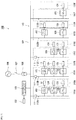
- Fig. 1 is a block diagram illustrating a schematic configuration of a combined power generation system according to an embodiment of the present invention.
- a combined power generation system 100 includes an alternating current (AC) power supply system 113 in which a plurality of facilities 101A to 101E (hereinafter; simply referred to as facilities 101X in some cases) are connected to each other to be capable of exchanging power with each other.
- AC alternating current
- the plurality of facilities 101A to 101E include intra-facility power distribution systems 112A to 112E branched from an inter-fecility power distribution system 102, respectively. At least one of a power storage installation 103, a power generating installation 104, and a load installation 105 is connected 10 each of the intra-facility power distribution systems 112A to 112E. Therefore, the intra-facility power distribution systems 112A to 112E are connected to the inter-fecility power distribution system 102, so that the power supply system 113 includes at least one of the power storage installation 103, the power generating installation 104, and the load installation 105.
- each of the intra-facility power distribution systems 112A and 112B includes the power storage installation 103, the power generating installation 104, and the load installation 105
- the intra-facility power distribution system 112C includes the power generating installation 104 and the load installation 105
- the intra-facility power distribution system 112D includes the power storage installation 103 and the load installation 105
- the intra-facility power distribution system 112E includes the load installation 105.
- the number of facilities may be more or less than that described above.
- facilities having no load installation 105 may be connected to the intra-fecility power distribution systems.
- the facility 101X is, for example, a general house, a public facility, a plant, a building or the like, and is a facility including at least one of the power storage installation 103, the power generating installation 104, and the load installation 105, the facility 101X may be a facility of the present combined power generation system 100.
- the combined power generation system 100 includes a control device 110X which performs control related to power exchange of each installation provided in the corresponding facility 101X for each of the plurality of facilities 101X,
- the control device 110X includes at least any one of a first system control device 11 which controls the power storage installation 103, a second system control device 124 which controls the power generating installation 104, and a third system control device 131 which controls the load installation 105 according to the facility provided in corresponding facility 101X.
- Each of the intra-facility power distribution systems 112A, 112B, and 112C including the power generating installation 104 has a received power measurer 111 which measures received power supplied to the intra-facility power distribution systems 112A, 112B, and 112C including the power generating installation 104.
- the received power measurer 111 is provided at a connection point (power receiving point) between each of the intra-facility power distribution systems 112A, 112B, and 112C and the inter-facility power distribution system 102.
- the power supply system 113 is connected to a commercial system 106 via a breaker 107 and a transformer 108, and the breaker 107 opens and doses, so that the power supply system 113 is switched between a linked operation state with the commercial system 106 and a self-sustaining operation state from the commercial system 106. Furthermore, a photovoltaic power generating facility 109 which is a power generating facility using natural energy is connected to the power supply system 113.
- Each load installation 105 receives power supplied from at least one of the power storage installation 103, the power generating installation 104, the commercial system 106, and the photovoltaic power generating facility 109 and consumes the power
- the photovoltaic power generating facility 109 is controlled by a fourth system control device 132
- the photovoltaic power generating facility 109 may be installed independently of the facilities 101X as illustrated in Fig. 1 or may be installed as one installation constituting any one of the facilities 101X.
- the photovoltaic power generating facility 109 is not an essential component
- a power generating facility using other natural energy such as a wind power generating facility and the like may be installed in the combined power generation system 100 instead of the photovoltaic power generating facility 109.
- a control device may be installed independently of each of the installations 103,104,105, and 109.
- one control device which controls the plurality of facilities 101X may be installed.
- the control devices of the power storage installation 103, power generating installation 104, and load installation 105 and the control device of the photovoltaic power generating facility 109 may be configured by one control device.
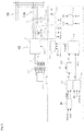
- FIG. 2 is a block diagram illustrating a schematic configuration of a power storage installation illustrated in Fig. 1 .
- each power storage installation 103 has a power storage device 5 and a first power converter 6 connected to the power storage device 5 to convert direct current power of the power storage device 5 into predetermined alternating current power.
- the power storage device 5 is connected to the first power converter 6 via a direct current power line 7.
- a primary battery, a secondary battery, an electric double layer capecitor, and the like can be used as the power storage device 5.
- a voltage measurer 4 for measuring a voltage of the power supply system 113 and a frequency calculator for calculating a frequency from a voltage measured in the voltage measurer 4 and a current measurer 3 for measuring a current (power receiving current) flowing through the intra-facility power distribution systems 112X are installed.
- a value measured by the voltage measurer 4 installed in any one of the power supply systems 113 may be commonly used in each facility 100X.
- An output of the voltage measurer 4 is connected to a voltage/rotational speed/phase calculation unit 14 of the first system control device 11 via wiring 22.
- the voltage measurer 4 is a transformer known as a potential transformer (PT) and the current measurer 3 is a transformer known as a current transformer (CT).
- PT potential transformer
- CT current transformer
- the first system control device 11 includes a first active power command value calculation unit 96, the current calculation unit 13, the voltage/rotational speed/phase calculation unit 14, an active and reactive calculation unit 15, a rotational speed command value calculation unit 40, an internal electromotive voltage command value calculation unit 50, an internal phase difference angle calculation unit 60, a current command value calculation unit 70, and a power converter control unit 16, and is configured to control the first power converter 6.
- the current command value calculation unit 70 in the first system control unit 16 functions as a first current command value calculation unit and the power converter control unit 16 functions as a first power converter control unit
- a gate driving signal 20 from the power converter control unit 16 is transmitted to the first power converter 6.
- the gate driving signal 20 performs PWM control of a gate of a power semiconductor device, so that the direct current power of the power storage device 5 is converted into alternating current power having a predetermined voltage, a rotational speed, and a phase and is supplied to the intra-facility power distribution system 112X.
- the alternating current power form the intra-facility power distribution system 112X is converted into direct current power to charge the power storage device 5.
- a state detector 17 for detecting states ofa battery such as a voltage, a current, a temperature, a pressure, and the like of the power storage device 5 is attached to the power storage device 5.
- a power storage device monitoring apparatus 18 monitors a state of the power storage device 5 and performs calculation of a state of charge (SOC) of the power storage device 5 based on asignal from the state detector 17.
- SOC state of charge
- the power storage device monitoring apparatus 18 is connected to the first system control device 11 via wiring 23.
- the first system control device 11 stops an operation of the first power converter 6 via the first power converter control unit 16 in a case where an abnormality is detected in the state of the power storage device 5.
- the first system control device 11 transmits the SOC of the power storage device 5 to the first system control device 11.
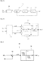
- Fig. 3A is a control block diagram illustrating a PLL calculation circuit in voltage/rotational speed/phase calculation unit illustrated in Fig. 2 and Fig. 3B is a diagram illustrating a more specific calculation content of the PLL calculation circuit illustrated in Fig. 3A .
- the rotational speed and phase of the power supply system 113 are obtained by calculation in a PLL calculation circuit 31 based on a voltage signal from the voltage measurer 4. Specifically, instantaneous values v RS , v ST of a line voltage of the power supply system 113 are measured by the voltage measurer 4 installed in the first power converter 6 and are input to the PLL calculation circuit 31. In the PLL calculation circuit 31, an estimation calculation of the rotational speed and phase of the power supply system 113 is performed using the instantaneous values v RS , v ST at the voltage.
- the PLL calculation circuit 31 includes an ⁇ converter 30 calculating a phase ⁇ from line voltage values (v RS , v ST ), a phase comparator 32 calculating a deviation between the phase ⁇ calculated by the ⁇ converter 30 and a phase ⁇ ' (hereinafter, estimation phase) estimated in the PLL calculation circuit 31, a loop filter 34 estimating an angular velocity (frequency) of the power supply system 113 from the phase deviation, and an integrator 35 integrating an estimated angular velocity and calculating the phase estimation phase ⁇ '.
- the phase ⁇ of the power supply system 113 can be obtained by performing ⁇ convesion of the instantaneous values v RS , v ST of a system line voltage obtained from the voltage measurer 4.
- the instantaneous values of a phase voltage in each phase of the system are set as v R , v S , and v T and an instantaneous value vector v ⁇ is defined as the following mathematical formula.
- v ⁇ 2 3 v R + v S e j 2 ⁇ ⁇ 3 + v T e j 4 ⁇ ⁇ 3
- v ⁇ v ⁇ 2 3 1 ⁇ 1 / 2 ⁇ 1 / 2 0 3 / 2 ⁇ 3 / 2 v R v S v T
- the instantaneous value vector v ⁇ is a vector rotating at an angular velocity ⁇ on a fixed coordinate system ( ⁇ axis) based on an a phase.
- the angular velocity ⁇ coincides with an angular frequency of the system voltage.
- the instantaneous value vector can be calculated from the instantaneous line voltage as described below.
- phase deviation a deviation ⁇ - ⁇ ' (hereinafter, referred to as phase deviation) between the phase ⁇ obtained from the instantaneous value of the system voltage and the phase ⁇ ' estimated in the PLL calculation circuit 31. Specifically, the phase deviation is calculated by the calculation as described below.
- the loop filter 34 calculates the rotational speed of the power supply system 113 from the phase deviation calculated by the phase comparator 32.
- a rotational speed (estimated synchronous rotational speed) ⁇ s of the power supply system 113 is obtained from an output of the loop filter 34.
- the rotational speed ⁇ s is integrated by the integrator 35 to obtain the estimation phase ⁇ '. Since the PLL calculation circuit operates such that the phase deviation ⁇ - ⁇ ' is set to be zero, it is apparent that the estimation phase ⁇ ' and the estimated synchronous rotational speed ⁇ s are estimation values of the phase ⁇ and the rotational speed ⁇ , respectively.
- the voltage/rotational speed/phase calculation unit 14 calculates the voltages V d , V q , the rotational speed ⁇ s of the power supply system 113, and the estimation phase ⁇ ' from the instantaneous values v RS , v ST of the line voltage from the voltage measurer 4.
- the current calculation unit 13 calculates currents I d, I q by the following mathematical formula using the estimation phase ⁇ ' calculated by the voltage/rotational speed/phase calculation unit 14 as input.
- the current vector at the dq coordinate system is the following mathematical formula.
- I d I q cos ⁇ ⁇ ′ cos ⁇ ′ ⁇ 2 3 ⁇ cos ⁇ ′ ⁇ 4 3 ⁇ ⁇ sin ⁇ ⁇ ′ ⁇ sin ⁇ ′ ⁇ 2 3 ⁇ ⁇ sin ⁇ ′ ⁇ 4 3 ⁇ i R i S i T
- the active and reactive power calculation unit 15 calculates active power P and reactive power Q using the voltages V d V q calculated by the voltage/rotational speed/phase calculation unit 14 and the currents I d I q calculated by the current calculation unit 13 as inputs. That is, in the present embodiment, the current measurer 3, the voltage measurer 4, the current calculation unit 13, the voltage/rotational speed/phase calculation unit 14, and the active and reactive power calculation unit 15 which are provided in the power storage installation 103 function as a first measurer which measures a value for obtaining active power and reactive power at an output terminal of a first power converter 6.
- the first active power command value calculation unit 96 calculates a first active power command value P refl based on a deviation between the SOC of the power storage device 5 and the SOC command value SOC ref of the power storage device 5.
- Fig. 4 is a control block diagram illustrating a calculation content of the first active power command value calculation unit 96 illustrated in Fig. 2 As illustrated in Fig. 4 , the first active power command value calculation unit 96 has a subtracter 93 and an active power command value setter 94. The subtracter 93 calculates a deviation ⁇ SOC between the SOC command value SOC ref and the SOC calculated by the power storage device monitoring apparatus 18.
- the first active power command value calculation unit 96 is configured to set the first active power command value P refl to be a negative value. That is, when the output ⁇ SOC of the subtracter 93 exceeds a predetermined value (for example, + 10%), the first active power command value setter 94 sets the first active power command value P refl to be a value (negative value; for example, 20% of rated power) for charging the power storage device 5. In addition, when the output ⁇ SOC of the subtracter 93 is less than a predetermined value (for example, -10%), the first active power command value setter 94 sets the first active power command value P refl to be a value (positive value, for example, 20% of rated power) for discharging the power storage device 5.
- a predetermined value for example, + 10%
- the first active power command value setter 94 sets the first active power command value P refl to be a value (negative value; for example, 20% of rated power) for charging the power storage device 5.
- a predetermined value for example,
- the control at the time of changing the power storage installation 103 can be an aspect simulating the virtual generator
- the active power command value setter 94 sets predetermined values (each on a change side and a discharge side) for changing the first active power command value P refl to have a hysteresis.
- the first active power command value calculation unit 96 may calculate the first active power command value P refl by multiplying the output ⁇ SOC of the subtracter 93 by a predetermined proportional gain K.
- the rotational speed command value calculation unit 40 calculates a virtual rotational speed command value ⁇ ref according to a predetermined frequency droop characteristic and a predetermined inertia characteristic in the virtual generator from the first active power command value P refl , the active power P, and the reference rotational speed ⁇ o .
- the rotational speed command value calculation unit 40 of the power storage installation 103 functions as a first rotational speed command value calculation unit which calculates a first virtual rotational speed command value.
- the rotational speed command value calculation unit 40 calculates the virtual rotational speed command value (first virtual rotational speed command value) ⁇ ref by proportional control from a deviation between the first active power command value P refl and the active power P.
- Fig 5A is a control block diagram illustrating an example of a calculation content of the rotational speed command value calculation unit 40 illustrated in Fig 2 .
- the rotational speed command value calculation unit 40 includes the subtractor 43, a proportion controller (first proportion calculator) 44, an upper/lower limiter 46, and an adder (first adder) 47.
- the subtracter 43 subtracts the active power P from the first active power command value P ref and outputs the subtracted result to the proportion controller 44.
- the proportion controller 44 multiplies the output of the subtractor 43 by a proportional gain (Dr), and transmits the multiplied result to the upper/lower limiter 46 of the next stage. Then, the upper/lower limiter 46 limits and outputs the output of the proportion controller 44 between ⁇ dr_max and ⁇ dr_min
- the adder 47 adds the reference rotational speed ⁇ o to the output of the upper/lower limiter 46, and outputs the added result as the rotational speed command value ⁇ ref .
- Fig. 5B is a control block diagram illustrating another example of the calculation content of the rotational speed command value calculation unit 40 illustrated in Fig 2 . That is, as illustrated in Fig. 5B instead of Fig. 5A , a first-order lag calculation unit 45 maybe disposed between the proportion controller 44 and the upper/lower limiter 46. The proportional gain (Dr) of the proportion controller 44 is adjusted so as to have a predetermined drooping characteristic between the active power and the rotational speed.
- Dr proportional gain
- Fig 6A is a control block diagram illustrating an example of a calculation content of the internal electromotive voltage command value calculation unit 50 illustrated in Fig 2 .
- the internal electromotive voltage command value calculation unit 50 calculates an internal electromotive voltage command value E f by proportional control from a deviation between a reactive power command value Q ref and reactive power Q.
- the internal electromotive voltage command value calculation unit 50 of the power storage installation 103 functions as a first internal electromotive voltage command value calculation unit which calculates a first virtual internal electromotive voltage command value
- the internal electromotive voltage command value calculation unit 50 includes a subtractor 53, a proportion controller (second proportional operator) 54, an upper/lower limiter 56, an adder (second adder) 57, and a function calculator 58.
- the subtracter 53 subtracts the reactive power Q from the reactive power command value Q ref , and outputs the subtracted result to the proportion controller 54.
- the proportion controller 54 multiplies the output of the subtractor 53 by a proportional gain (Dr), and transmits the multiplied result to the upper/lower limiter 56 of the next stage.
- Dr proportional gain
- the upper/lower limiter 56 limits and outputs the output of the proportion controller 54 between V dr_max and V dr_min
- the adder 57 adds a voltage reference value V o to the output of the upper/lower limiter 56 to output a voltage target value V ref .
- the voltage target value V ref is sent to the function calculator 58.
- the function calculator 58 performs the calculation shown in the following mathematical formulas, and outputs the internal electromotive voltage command value E f.
- E fd V ref + rI d ⁇ xI q
- E fq rI q + xI q
- E f E fd 2 + E fq 2
- the internal electromotive voltage command value E f determined by the above mathematical formula may be obtained by subtracting from the voltage target value V ref which is the output of the second adder 57, a voltage drop due to a total impedance (r, x) which is a sum of an internal impedance of the power storage installation and an external impedance between the power storage installation and the power supply system (see Fig. 8B to be described below).
- the internal impedance can be determined, for example, by Thevenin's theorem. As will be described later, the internal impedance in an actual motor is generally said to be a very small value (almost zero).
- the external impedance consists of a reactor and a wiring resistance provided between the first power converter 6 and the power supply system 113. Since a value of current flowing in the first power converter 6 is measured, the internal electromotive voltage can be obtained from the voltage value of the power supply system 113 by an inverse calculation if the total impedance is determined.
- Fig. 6B is a control block diagram illustrating another example of the calculation content of the internal electromotive voltage command value calculation unit 50 illustrated in Fig 2
- the internal electromotive voltage command value calculation unit 50 calculates the internal electromotive voltage command value E f from a reactive power command value Q ref and reactive power Q.
- the internal electromotive voltage command value calculation unit 50 includes the subtractor 53, the proportion controller (second proportional operator) 54, the upper/lower limiter 56, and the adder (second adder) 57.
- the internal electromotive voltage command value calculation unit 50 includes a second function calculator 58B having a different calculation formula instead of the function calculator 58 in Fig. 6A .
- the voltages V d , V q are input to the second function calculator 58B instead of the currents I d , I q .
- the second function calculator 58B performs the calculation shown in the following mathematical formulas, and outputs the internal electromotive voltage command value E f.
- the internal electromotive voltage command value E f obtained by the above mathematical formula is a command value which droops the voltage command value according to a deviation of the reactive power to make The actual voltage follow the voltage command value. That is, the internal electromotive voltage command value E f in this example is a value obtained by simulating a voltage command value based on the control of a magnetic field by an automatic voltage regulator (AVR) performed by a normal generator.
- AVR automatic voltage regulator
- Fig. 6C is a control block diagram illustrating another example of the calculation content of the internal electromotive voltage command value calculation unit 50 illustrated in Fig. 2 . That is, as illustrated in Fig. 6C , the internal electromotive voltage command value calculation unit 50 includes a first-order lag calculation unit 55 disposed between the proportion controller 54 and the upper/lower limiter 56, instead of directly inputting the output of the proportion controller 54 to the upper/lower limiter 56 as illustrated in Figs. 6A and 6B .
- the proportional gain (Dr) is adjusted to have a predetermined drooping characteristic between the reactive power and the output voltage.
- Fig. 7 is a control block diagram illustrating a calculation content of an internal phase difference angle calculation unit 60 illustrated in Fig. 2 .
- the internal phase difference angle calculation unit 60 calculates an internal phase difference angle ⁇ from a deviation between the virtual rotational speed command value ⁇ ref and a synchronous rotational speed ⁇ s of the power supply system 113.
- the internal phase difference angle calculation unit 60 of the power storage installation 103 functions as a first internal phase difference angle calculation unit which calculates a virtual first internal phase difference angle
- the internal phase difference angle calculation unit 60 has a subtractor 63 and an integrator 64.
- the subtractor 63 calculates the deviation between the rotational speed command value ⁇ ref and the synchronous rotational speed ⁇ s .
- the integrator 64 provided in the next stage of the subtractor 63 integrates this deviation and outputs the integrated result as an internal phase difference angle ⁇ .
- a rotational speed (unit rpm) is compared using the virtual rotational speed command value ⁇ ref and the synchronous rotational speed ⁇ s , but an angular velocity (unit: rad/sec), the number of revolutions (unit: Hz) and the like may be compared.
- the angular velocity, the number of revolutions, and the frequency are concepts equivalent to the rotational speed. Therefore, the frequency of the power supply system 113 described below is also obtained from the synchronous rotational speed ⁇ s in the voltage/rotational speed/phase calculation unit 14.
- Fig. 8A is a control block diagram illustrating a calculation content of a current command value calculation unit 70 illustrated in Fig. 2 .
- Fig. 8B is a conceptual diagram of the power supply system according to the present embodiment
- the internal electromotive voltage command value E f the internal phase difference angle ⁇ , and the voltages V d , V q are input to a function calculator 72.
- the function calculator 72 performs a calculation of the following mathematical formulas, and outputs current command values I d_ref , I q_ref to the power converter control unit 16.
- the current value determined by the above mathematical formula is a value of current flowing in the total impedance, if it is assumed that the total impedance is connected between the power supply of the system voltage measured by the voltage measurer 4 and the power supply of the internal electromotive voltage command value voltage.
- the current value is output as a first current command value from the current command value calculation unit 70 of the power storage installation 103 (see Fig. 8B ).
- the internal impedance of the power storage installation 103 virtually increases to obtain the total impedance, and when the internal electromotive voltage command value E f and the first current command values I d_ref , I q_ref are calculated using the virtual impedance, the stable operation can be achieved.
- the reason is as follows: when the plurality of first power converters 6 operate in parallel, the output balance largely collapses due to a slight voltage difference between the first power converters 6 because the impedance of the first power converter 6 is low, and the impedance of the first power converter 6 increases by virtually increasing the internal impedance of the power storage installation 103, and as a result, the output balance can be prevented from being unstable due to the voltage difference. For example, since the internal impedance is substantially zero, if a resistance component is 0.1 pu and a reactance component is 0.4 pu in the total impedance, considerable stabilization can be achieved.
- the current command value calculation unit 70 estimates the current value output to the intra-facility power distribution system 112X.
- the apparent impedance of the first power converter 6 increases, and the system is suppressed from becoming unstable even in the case of any one of the linkage operation with the commercial system 106 and the parallel operation of the power conversion devices.
- the power converter control unit 16 receives the estimation phase ⁇ ' calculated by the voltage/rotational speed/phase calculation unit 14, the currents I d , I q calculated by the current calculation unit 13, and the first current command values I d_ref , I q_ref calculated by the current command value calculation unit 70.
- the power converter control unit 16 outputs the gate driving signal 20 such that the output current of the first power converter 6 becomes the first current command value calculated by the current command value calculation unit 70.
- the power storage device monitoring apparatus 18 if abnormality is detected in the power storage device 5, a battery abnormality signal is transmitted to the power converter control unit 16 of the system control device 11 via the wiring 23, and the transmission of the gate driving signal 20 is stopped. Accordingly, the operation of the first power converter 6 is stopped, so that the power storage device 5 can be protected.
- the abnormality of the power storage device include overcurrent, voltage drop, overvoltage, overcharge, overdischarge, battery temperature abnormality, battery pressure abnormality, device abnormality and the like.
- the power storage device monitoring apparatus 18 calculates the SOC of the power storage device 5 and transmits the calculated SOC to the system control device 11 via the wiring 23.
- the SOC is calculated by correcting the SOC (integrated SOC) obtained by accumulating the current flowing in the power storage device with the SOC instantaneous SOC) obtained from the current, the voltage, and the temperature.
- the power converter 6 controls the output of the active power to decrease, and conversely when the SOC of the power storage device 5 is larger than the SOC command value to be targeted, the power converter 6 controls the output of the active power to increase. As a result, the SOC of the power storage device 5 is maintained in an appropriate range.
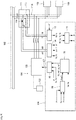
- Fig. 9 is a block diagram illustrating a schematic configuration in a case where the power generating installation illustrated in Fig. 1 is connected to the intra-facility power distribution system via the power converter
- those common to the control block of the first system control device 11 illustrated in Fig. 2 are denoted by the same reference numbers, and the description thereof will be omitted.
- the example of Fig. 9 illustrates the intra-facility power distribution system 112A to which the power storage installation 103 and the load installation 105 are connected in addition to the power generating installation 104
- the power generating installation 104 can employ the same configuration as the example of Fig.
- each of the power generating installations 104 has a power generation device 122 and a second power converter 125 connected to the power generation device 122 to convert power of the power generation device 122 into ptedetermined AC power
- the power generation device 122 is a power generation device capable of perfuming output control, and for example; a fuel cell power generation device, or a motor driven power generation device such as a diesel power generation device and a tubine power generation device can be employed. Even if the power generation device is a photovoltaic power generation device, a wind power generation device or the like, whose power output is dependent on natural conditions, it can be employed as long as output control is possible. Further, the second power converter 125 may not be provided in the motor driven power generation device.
- the power generation device 122 (for example, a fuel cell power generation device) is connected to the power generating installation 104.
- the power generation device 122 is connected to the second power converter 125.
- the second power converter 125 operates by receiving a gate driving signal 127 from the second system control device 124 via a wiring.
- the second system control device 124 is configured to control the second power converter 125.
- the received power measurer 111 indudes a current measurer 115 which measures the current of the intra-facility power distribution system 112A, and a voltage measurer 114 which measures the voltage of the intra-facility power distribution system 112A.
- the current measured by the current measurer 115 and the voltage measured by the voltage measurer 114 are input to the second system control device 124.
- the active and reactive power calculation unit 15 calculates the active power P and the reactive power Q using the voltages V d , V q calculated by the voltage/rotational speed/phase calculation unit 14 and the currents I d, I q calculated by the current calculation unit 13 as inputs.
- the active power P output from the active and reactive power calculation unit 15 is received power P supplied to the intra-facility power distribution system 112A. Therefore, the received power P supptied to the intra-facility power distribution system 112A can be obtained from the current and voltage measured by the received power measurer 111.
- a second active power command value calculation unit 86 calculates a seconde active power command value P ref2 based on the frequency f of the power supply system 113 calculated by the voltage/rotational speed/phase calculation unit 14, a reference frequency f o , and the received power P calculated by the active and reactive power calculation unit 15.
- the current command value calculation unit 70 of the power generating installation 104 receives the second active power command value P ref2 and the system voltages V d , V q , and outputs the current command values I d_ref , I q_ref that the second power converter 125 should output
- the mathematical formula for this is given by, for example, the following mathematical formula.
- I d _ ref V d V d 2 + V q 2 P ref 2
- I q _ ref V q V d 2 + V q 2 P ref 2
- a power control loop may be configured which sets the second active power command value P ref2 to be a target value by well-known governor control without providing the second power converter 125. That is, when the power generation device 122 employs a power generation device using a motor driven generator, the power generation device 122 is configured so that the generator is directly incorpored into the intra-fecility power distribution system 112A synchronously, and the driving force of the motor driving the generator may be controlled so that the output of the generator follows the second active power command value P ref2 .
- Fig. 10 is a control block diagram illustrating an example of a calculation content of the second active power command value calculation unit 86 illustrated in Fig. 9 .
- the second active power command value calculation unit 86 includes a subtractor 83, a first generated power change rate command value calculation unit 84, a second generated power change rate command value calculation unit 85, an adder 87, and an integrator 88.
- the first generated power change rate command value calculation unit 84 calculates a first generated power change rate command value R f from the deviation ⁇ f.
- the fist generated power change rate command value calculation unit 84 outputs the first generated power change rate command value R f for increasing an amount of power generation of the power generation device 122 when the frequency f is lower than the reference frequency f o , and outputs the first generated power change rate command value R f for decreasing an amount of power generation of the power generation device 122 when the frequency f is higher than the reference frequency f o .
- the first generated power change rate command value calculation unit 84 changes the first generated power change rate command value R f so that the first generated power change rate command value R f increases by 20%/min for each deviation ⁇ f of +2%, and changes the first generated power change rate command value R f so that the first generated power change rate command value R f decreases by 20%/min for each deviation ⁇ f of 2%.
- the second generated power change rate command value calculation unit 85 calculates a second generated power change rate command value R p from the received power P of the corresponding intra-facility power distribution system 112A. In a case where the received power P is a value indicating that the curresponding intra-farility power distribution system receives power (P > 0) the second generated power change rate command value calculation unit 85 outputs the second generated power change rate command value R p for increasing the amount of power generation of the powergeneration device 122.
- the second generated power change rate command value calculation unit 85 changes the second generated power change rate command value R p by +10%/min.
- the second generated power change rate command value calculation unit 85 outputs the second generated power change rate command value Rp for increasing the amount of power generation of the power generation device 122. That is, the second generated power change rate command value calculation unit 85 outputs a command value for maintaining the amount of power generation of the power generation device 122, regarding a period in which the received power P is 0 to the predetermined positive value as a dead zone.
- the second active power command value calculation unit 86 performs a setting so that the degree of influence of the first generated power change rate command value R f on the second generated power change rate command value R p is increased. For example, as described above, a change in the first generated power change rate command value R f based on the change in frequency is made with 20%/min as a minimum unit, whereas a change in the second generated power change rate command value R p based on the change in received power is made with 10%/min as a minimum unit
- the adder 87 outputs a generated power change rate command value R g obtained by adding the first generated power change rate command value R f and the second generated power change rate command value R p .
- the integrator 88 calculates the second active power command value P ref2 by integrating the generated power change rate command value R g .
- the second system control device 124 includes the rotational speed command value calculation unit 40, the internal electromotive voltage command value calculation unit 50, the internal phase difference angle calculation unit 60, the current command value calculation unit 70, and the power converter control unit 16, similarly to the first system control device 11.
- the current command values I d_ref I q_ref output from the current command value calculation unit 70 of the second system control device 124 become second current command values which are command values of the output current of the second power converter 6.
- the rotational speed command value calculation unit 40, the internal dectromotive voltage command value calculation unit 50, the internal phase difference angle calculation unit 60, and the current command value calculation unit 70 of the first system control device 11 functions as the first rotational speed command value calculation unit, the first internal dectromotive voltage command value calculation unit, the first internal phase difference angle calculation unit, and the first current command value calculation unit, respectively.
- the first system control device 11 controls the changing and discharging of the power storage device 5 using the first power converter 6, so that the power storage installation 103 functions as a virtual generator. That is, in the power storage installation 103, a command value of the output current of the first power converter 6 is input, so that a dosed loop control system of active power of the first power converter 6 and the frequency of the power supply system 113, and a closed loop control system of reactive power of the first power converter 6 and the voltage of the power supply system 113 are formed, and control amounts (amounts to be controlled) thereof are feedback-controlled.
- the power storage installation 103 functions as both the current control type and the voltage control type, and includes a power converter capable of performing parallel operation in a self-sustaining state without changing a control mode in a case of switching from a self-sustaining operation to a linkage operation, or switching from a linkage operation to a self_sustaining operation. Further since the feedback control system of the power storage installation 103 is realized by software, not by an actual generator, a response speed is faster than the actual generator.
- the first power converter 6 for the power storage installation 103 functioning as a virtual generator is used in addition to the second power converter 125 for the power generating installation 104, so that the excess and deficiency of the generated power of the power generating installation 104 to the load power can be compensated by the power storage installation 103 of which the response speed is faster in comparison to the power generating installation 104.
- a change in SOC of the power storage device is compensated using the first power converter 6 by the operation of the first system control device 11.
- the frequency of the power supply system 113 is increased or decreased according to the increase or decrease in an amount of load connected to the power supply system 113 and in an amount of the charging and discharging of the power storage installation by the operation of the power storage installation 103 as a virtual generator, so feat according to the change in frequency it is possible to achieve balance between the amount of the entire load of the power supply system 113 and the amount of the changing and discharging of the power storage installation, and the amount of power generation by increasing or decreasing the power generation output of the power generating installation 104.
- power generated by the power generating installation 104 of each facility is adjusted according to the received power amount of each facility, so that power consumed in each facility is adjusted to be generated in the same facility as far as possible. That is, it is possible to appropriately perform load sharing of the power generating installations 104 in the respective facilities.
- the second active power command value P ref2 is set to a value for increasing the degree of influence of the first generated power change rate command value R f on the second active power command value P ref2 with respect to the second generated power change rate command value R p .
- the second system control device 124 may control the power generating installation 104 to start power generation when the frequency fof the power supply system 113 calculated by the frequency calculator becomes less than a preset first threshold value and the state where the frequency f is less than the first threshold value is continued for a predetermined time, and the second system control device 124 may control the power generating installation 104 to stop power generation when the frequency f becomes equal to or greater than a preset second threshold value as a value equal to or greater than the first threshold value and the state where the frequency f is equal to or greater than the second threshold value is continued for a predetermined time.
- the received power measurer 111 is provided in each of the intra-facility power distribution systems 112A, 112B, and 112C including the power generating installation 104
- the received power measurer 111 may be provided in other intra-facility power distribution systems 112D and 112E.
- the power received by each intra-facility power distribution system 112X is acquired, so that it is possible to grasp the power supply and demand situation between each facility 101X and other facilities.
- the second system control device 124 which controls the power generating installation 104 can adjust the amount of power generation of the power generating installation 104 according to the power supply and demand situation.
- Fig. 11 is a control block diagram illustrating another example of the calculation content of the second active power command value calculation unit illustrated in Fig. 9 .
- the second system control device 124 may include a command value correction calculation unit 92 which corrects the second active power command value P ref2 based on a value obtained by accumulating the received power
- the command value correction calculation unit 92 includes an integrator 89, a third generated power change rate command value calculation unit 90, and an adder 91.
- the integrator 89 accumulates the received power P of the intra-facility power distribution system for a predetermined period, and outputs a power amount W of the facility.
- the power amount W of the facility becomes a negative value when the supply of power to the outside of the facility 101X is continued, and becomes a positive value when the reception of power in the facility 101X is continued.
- the third generated power change rate command value calculation unit 90 generates a third generated power change rate command value R W based on the power amount W of the facility output from the integrator 89. For example, when the power amount W of the facility is a positive value, the third generated power change rate command value calculation unit 90 changes the third generated power change rate command value R W by +5%/min.
- the third generated power change rate command value calculation unit 90 changes the third generated power change rate command value R W by -5%/min.
- the third generated power change rate command value calculation unit 90 outputs a command value for maintaining the amount of power generation of the power generation device 122, regarding a period in which the power amount W of the facility is 0 to a predetermined value as a deal zone.
- the adder 91 outputs the generated power change rate command value R g obtained by adding an output of the adder 87 obtained by adding the first generated power change rate command value R f and the second generated power change rate command value R p , and the third generated power change rate command value R W .
- the integrator 88 calculates the second active power command value P ref2 by integrating the generated power change rate command value R g .
- the commad value correction calculation unit 92 may add a corrected value of the second active power command value P ref2 based on the power amount W of the facility to an output of the integrator 88.
- the second system control device 124 controls the amount of power generation of the power generating installation 103 in the facility 101X to increase when the power amount W in the facility 101X is excessively received power (positive value), and controls the amount of power generation of the power generating installation 103 in the facility 101X to decrease when the power amount W in the facility 101X is excessively transmitted power (negative value).
- the power generating installation 103 in the facility 101X is controlled so that the power amount W in the facility 101X approaches zero.
- the third generated power change rate command value calculation unit 90 is configured to reduce the degree influence of the third generated power change rate command value Rw on the first generated power change rate command value R f and the second generated power change rate command value R p . Accordingly, it is possible to perform the supply and demand offset processing of power while suppressing the influence on the supply and demand balance.
- the load power of the load installation 105 may be adjusted according to the power supply and demand situation of the entire power supply system 113.
- the third system control device 131 controls the power consumed by the load installation 105 to decrease when the third system control device 131 is in a state where the frequency of the power supply system 113 is less than a preset third threshold value, and the state where the frequency of the power supply system 113 is less than the third threshold value is continued for a predetermined time.
- the supply and demand condition of the power supply system 113 can be determined from the fluctuation of the frequency of the power supply system 113.
- the increment in load is temporarily shared and borne by the power storage installation 103 and the frequency of the power supply system 113 decreases based on the drooping characteristic in the virtual generator control for the first power converter 6 of the power storage installation 103.
- each power generating installation 104 increases an output to maintain the supply and demand balance.
- the shortage is supplied from the power storage installation 103.
- the frequency of the power supply system 113 is lower than the reference frequency (rated frequency), and this state is continued.
- the SOC of the power storage device 5 decreases, so that the first active power command value P ref1 to the first power converter 6 becomes a negative value, and the frequency of the power supply system 113 further decreases (which becomes less than the third threshold value) due to the drooping characteristic of the virtual generator.
- the third system control device 131 controlling the load installation 105 determines that the power supplied in the entire power supply system 113 is insufficient and performs the suppression operation or stop operation of the load installation 105.
- the order in which the suppression operation or the stop operation is performed in the plurality of load installations 105 can be adjusted by setting the amount of decrease in frequency and the threshold value of duration.
- the third system control device 131 may directly give a suppression instruction or a slop instruction, such as an output, to the load installation 105, or may be provided with a breaker (for example, an electromagnetic contactor and the like) which is connected to or disconnected from the connection point between the load installation 105 and the power supply system 113 and may issue an instruction to the breaker to shut down the connection between the load installation 105 and the pawer supply system 113.
- the third system control device 131 may notify an alarm or the like to the facility 101X in which the oonreponding load installation 105 is induded, and urge the user of the load installation 105 to save power.
- the power generated by the power generating facility may be adjusted according to the power supply and demand condition of the entire power supply system 113.
- the fourth system control device 132 is in a state where the frequency of the power supply system 113 is equal to or greater than a preset fourth threshold value, and controls the power generated by the photovoltaic power generating facility 109 to decrease when the state where the frequency of the power supply system 113 is equal to or greater than the fourth threshold value continues for a predetermined time.
- the power storage installation 103 When the power generated by the photovoltaic power generating facility 109 increases, the power storage installation 103 temporarily charges a surplus. At this time, the frequency of the power supply system 113 increases due to the drooping characteristic of the virtual generator Accordingly, the output of the power generating installation 104 decreases, so that the supply and demand balance is maintained. When the power generated by the photovoltaic power generating facility 109 further increases, the entire power generated by the power generating installation 104 reaches a lower limit value, and the state of charging of the power storage installation 103 continues.
- the SOC of the power storags device 5 increases and the active power command value P ref for the first power converter 6 is a value (positive value) on the discharge side, so that the frequency of the power supply system 113 continues to increase (which becomes the state greater than the fourth threshold value).
- the fourth system control device 132 which controls the photovoltaic power generating facility 109 determines that power supplied to the entire power supply system 113 is excessive when the frequency of the power supply system 113 continues to increase for a predetermined time, and limits or stops the power output from the photovoltaic power generating facility 109.
- Examples of the method of limiting the output power of the photovoltaic power generating facility 109 can include a method in which the fourth system control device 132 issues an instruction for decreasing an upper limit value of the output of the photovoltaic power generating facility 109 or stops generating power in some of a plurality of segments in a case of the photovoltaic power generating facility 109 constituted by the plurality of segments which can be controlled individually.
- the first system control device 11 may reset the SOC command value of the power storage installation 103 to be a higher value.
- the supply of the power to the power supply system 113 can decrease without changing the control mode, and the supply and demand balance of the power in the power supply system 113 can be stably maintained.
- the power supply system 113 generally suffers from a shortage of supply of the power generating installation 104. For this reason, the power storage installation 103 is provided to discharge due to the shortage. As a result, the frequency of the power supply system 113 decreases due to the drooping characteristic of the power storage installation 103. As the frequency of the power supply system 113 decreases, the power generating installation 104 ofeach facility 101X increases the generated power. Since the received power Pis generated in the facility 101A (which becomes a positive value), the power generating installation 104 in the facility 101A increases the generated power so that the generated power becomes larger than the power generating installation 104 of other facilities.
- the power generated by the power generating installation 104 of the facility 101A increases, the output of the power storage installation 103 decreases, and the frequency of the power supply system 113 also increases. Eventually, the output of the power storage installation 103 becomes zero, and the frequency of the power supply system 113 also returns to the reference frequency.
- the power received by the facility 101A is a positive value
- the power generated by the power generating installation 104 of the facility 101A continues to increase, so the frequency of the power supply system 113 also continues to increase.
- the power storage installation 103 is changed to absorb the generated power which has increased.
- the frequency of the power supply system 113 increases, the power generated by the power generating installations 104 of other facilities decreases, and finally, only the power generating installation 104 of the facility 101A settles down in a state where the output increases.
- the frequency of the power supply system 113 also returns to the reference frequency
- the power generated by the power generating installations 104 of other facilities turns to increase, and thus the frequency of the power supply system 113 also increases again.
- the power generated by the power generating installation 104 of the facility 101A decreases, and finally, only the power generating installation 104 of the facility 101A settles down in a state where the output decreases.
- the power supply system 113 When the power generated by the photovoltaic power generating facility 109 increases, the power supply system 113 is in the state of the surplus of supply, the frequency of the power supply system 113 increases, and the power storage installations 103 of each facility 101X charge the surplus. As the frequency of the power supply system 113 increases, the power generating installations 104 of each facility 101X decrease the generated power and decrease the power accommodated outside the facility. When the power generated by the photovoltaic power generating facility 109 further increases, the power generating installations 104 of each facility 101X continue to decrease the generated power and settle down in a state of receiving power from outside the facility.
- the load installations 105 of each facility 101X are controlled to decrease or stop the load and to improve the shortage of supply.
- a case is considered in which the power generated by the photovoltaic power generating facility 109 increases and is in an excessive state of supply in a state where the load of the entire power supply system 113 decreases.
- the power generating installations 104 of each facility 101X decrease the generated power; and when the generated power reach the lower limit, the surplus is charged to the power storage device 5 of the power storage installation 103.
- the power storage installation 103 is adjusted to the discharge side, so the frequency of the power supply system 113 further increases.
- the frequency of the power supply system 113 is equal to or greater than the predetermined value (the fourth threshold value described above), and when the state where The frequency of the power supply system 113 is equal to or greater than the predetermined value continues for a predetermined time, it is determined that the power supply system 113 is the excessive supply, and the photovoltaic power generating facility 109 is controlled to perform the suppression or stop of the generated power and improve the excessive supply.
- the predetermined value the fourth threshold value described above
- All the facilities 101X included in the combined power generation system 100 of the present embodiment may be configured as a house, or facilities other than the house may be included.
- the facility 101X may include public facilities that are used as a shelter at the time of the occurrence of disasters like a gymnasium may be included.
- public facilities may include emergency power generating installations such as photovoltaic power generating facilities and/or diesel power generating installations.
- These power generating installations are configured as relatively large capacity (for example, several hundred kW) power generating installations.
- the power generated by the photovoltaic power generating facility can be supplied to the load in the public facilities, and the surplus can be supplied (sold) to the commercial power system, but when the commercial system fails due to disasters or the like, the surplus cannot be processed, and it becomes necessary to stop the power generation in the photovoltaic power generating facility.
- the emergency power generating installation needs to be always in operation during a power failure.
- the power failure such as a disaster; a situation may occur where the stored fuel required for power generation cannot be replenished due to the influence of the disaster or the like. In this case, the fuel may be exhausted and the emergency power generating installation may not operate.
- the self-sustaining power supply system can be constructed in public facilities and other facilities such as houses. Acoorcling to the present embodiment, the voltage and frequency of the self-sustaining power supply system are maintained by the power storage installation provided in other facilities. On the other hand, the surplus of the power generated by the photovoltaic power generating facility in the public facility is accommodated to other facilities such as a house. In addition, the emergency power generating installation in the public facilities needs to be operated only when it is determined that the power supply capacity in the self-sustaining power supply system is insufficient, and the consumption of fuel for the emergercy power generating installation is reduced as much as possible.
- the disaster accompanied by the power failure occurs, and nearby residents are evacuated to the above public facilities as a shelter, they are used as a shelter by limiting power consumption of other facilities such as a house, thereby effectively performing the supply of power to the public facilities which are used as a shelter.
- a blackout such as planned blackout where the public facility is not used as a shelter
- the load on the public facility is limited, and the power generated by the photovoltaic power generating facility of the public facility and the power generated by the emergency power generating installation can also be supplied to other facilities. Therefore, by configuring the combined power generation system 100 so that the public facilities are included in the system, it is possible to effectively use the power generating installations in the public facilities according to the situation of the power failure.
- the combined power generation system 100 according 10 the present embodiment is also applicable to remote islands and the like.
- the combined power generation system 100 is connected to a small-scale commercial system instead of a wide-scale commercial system 106.
- a fuel cost for power generation is high, and a power generation cost is high.
- a demand to introduce power generating facilities using natural energy such as solar light there is a demand to introduce power generating facilities using natural energy such as solar light.
- the power storage installation 103 since the power storage installation 103 has the same drooping characteristic as that of the motor generator, the effect of reinforcing the supply and demand adjustment capability of small-scale commercial system can be obtained. In addition, since there are simulated inertia moments and internal impedance, the effect of enhancing the stability of small-scale commercial system can be obtained. In addition, since the power generating installation 104 such as a fuel cell installed in each facility adjusts the generated power by following the load power of its own, the effect of reducing the load variation caused by the entire power supply system 113 is expected.
- the power can be accommodated to the small-scale commercial system As a result, the supply and demand adjustment capability and the system stability of the small-scale commercial system such as the remote island are enhanced, and the introduction of the power generating installation using natural energy becomes easy. Furthermore, the small-scale commercial system does not need to run an excess power generating installation, and the power generation cost can thus be reduced.
- a simulation shows that the combined power generation system according to the present invention can favorably distribute the load and interchange the power among a plurality of facilities.
- Figs. 12A and 12B are graphs illustrating a simulation result according to an embodiment of the present invention.
- Fig 12A is a graph illustrating a temporal change of each power value at each facility
- Fig. 12B is a graph illustrating a frequency change of the power supply system 113.
- the power supply system 113 includes three facilities 101A, 1018, and 101C in Fig. 1 .
- a photovoltaic power generating facility is not connected, and each facility has a power storage installation 103, a power generating installation 104, and a load installation 105.
- the power generating installation 104 is assumed to be a fuel cell power generating installation, and there are restrictions on the upper and lower limits and the rate of change of the generated power
- each of the facilities 101A, 1018, and 101C has loads of 100W 200W, and 300W, which are charged by the fuel cell power generating installation 104 of each facility.
- Figs. 12A and 12B illustrate the simulation results when a load of 800 W is added to the load of the facility 101A in a step shape at a time of 100 seconds.
- an increase in load is indicated by a solid line.
- a frequency decreases in the step shape as shown in Fig. 12B due to an operation of the power storage installation 103 as a virtual generator, but an increase in the output of the fuel cell power generating installation 104 indicated by a broken line in Fig. 12A is moderate due to the restriction of the rate of change of the output of the fuel cell power generating installation 104.
- an output of the power storage installation 103 indicated by a chain line in Fig. 12A is reduced (discharged) so that the power storage installations 103 of the three facilities 101A to 101C equally share the increase of the load at the beginning of the load increase.
- the output of the fuel cell power generating installation 104 gradually increases. Accordingly, a frequency of the power supply system 113 gradually rises, and the power shared by the power storage installation 103 decreases.
- the received power increases as indicated by the dotted line in Fig. 12A . For this reason, the fuel cell power generating installation 104 of the facility 101A continuously increases the amount of power generation so as to reduce the received power.
- the fuel cell power generating installations 104 of the facility 101B and the facility 101C decrease the output to reduce the power being transmitted after the frequency of the power supply system 113 returns to its original value (the received power is the power transmission side).
- the facility 101A is in a state of receiving the deficiency of 200W for the 900W that the initial load and the increased load are summed.
- the finality 100B and the facility 101C fall in a state where they share the deficiency of 200 W of the facility 101A for each 100 W.
- the power supply system to which the combined power generation system is applied is a three-phase system
- the power supply system is not limited thereto.
- the power supply system is a single-phase two-wire system or a single-phase three-wire system, it is possible to construct the same cambined power generation system except that the various calculation methods differ according to the manner of the system.
- the present invention is useful for appropriately perform load sharing of a power generating installation in a combined power generation system including a power conversion device capable of performing parallel operation in a self-sustaining state without changing a control mode in a case of switching from a self-sustaining operation to a linkage operation or from a linkage operation to a self-sustaining operation.
Landscapes
- Engineering & Computer Science (AREA)
- Power Engineering (AREA)
- Supply And Distribution Of Alternating Current (AREA)
- Charge And Discharge Circuits For Batteries Or The Like (AREA)
- Inverter Devices (AREA)
Abstract
Description
- The present invention relates to a combined power generation system.
- In a commercial power system supplied by a power company maintenance and management of power supply quality are mainly performed by the power company.
- On the other hand, a self-sustaining power supply system which is not connected to the commercial power system needs to perform maintenance and management of the power supply quality by oneself Examples of such a self-sustaining power supply system include a microgrid in which plural types of power supplies such as power generating installations such as a fuel cell power generating installation, a photovoltaic power generating installation, and a diesel power generating installation and power storage installations such as a secondary battery and an electric double layer capacitor are combined and networked in a certain area, and the like.
- In the power generating installations such as the fuel cell power generating installation and the photovoltaic power generating installation or the power storage installation, a power conversion device is provided for each power supply and power output from each power supply is controlled. There are two types of power conversion devices such as a current control type and a voltage control type according to a control method thereof
- The current control type power conversion device is controlled to output a predetermined current regardless of a voltage or a frequency ofa system connected thereto. The current control type power conversion device is mainly used as a power conversion device for system linkage. The voltage and frequency are premised to be maintained by other power generating installations (commercial system, motor generator; and the like), and the current control type power conversion devices cannot perform a self-sustaining operation alone or in combination.
- On the other hand, the voltage control type power conversion device is controlled to output power with a constant voltage and frequency regardless ofan output current The voltage control type power conversion device is mainly used as a power conversion device for a self-sustaining operation alone. A linkage operation with the system and a parallel operation between the voltage control type power conversion devices cannot be used because the output becomes unstable
- For this reason, conventionally, in a case of switching from a state where the miacrogrid or the like operates in conjunction with the commercial power system to the self-sustaining operation, or from the self-sustaining operation to the commercial power system linked operation, the control method of the power conversion device needs to be switched.
- In addition, in the self-sustaining power supply system, it is nocessary to make the generated power and power consumption of a load coincide with each other all the times. Furthermore, when the power supply system is constituted by a plurality of power generating installations having different characteristics, it is necessary to appropriately adjust load sharing according to the characteristics of each power generating installation.
- In order to solve such problems, PTL1 discloses performing virtual generator model control which controls a power amount received from a power storage installation under the assumption that a virtual generator is connected to a power system, as a configuration which performs switching between a linkage operation with a power system and a self-sustaining operation without instantaneous interruption, performs autonomous load faring among a plurality of power storage installations, or realizes system frequency stabilization in the short time.
- PTL1:
WO2013/008413A - However although the configuration of PTL1 discloses the control for the power storage installation in detail, there is room for improvement of the control for the power generating installation.
- An object of the present invention is to provide a combined power generation system that appropriately performs load sharing of a power generating installation, the combined power generation system including a power coversion device capable of performing parallel operation in a self-sustaining state without changing a control mode in a case of switching from a self-sustaining operation to a linkage operation or from a linkage operation to a self-sustaining operation.
- According to an aspect of the present invention, a combined power generation system configures a power supply system where intra-facility power distribution systems respectively installed in a plurality of facilities are connected to each other to be capable of exchanging power with each other via an inter-facility power distribution system. Each of the intra-facility power distribution systems includes at least one of a power storage installation which has a power storage device and a first power converter connected to the power storage device to convert direct current power of the power storage device into predetermined alternating current power, a power generating installation which has a power generation device capable of performing output control, and a load installation which consume power, and the power supply system includes at least one power storage installation, at least one power generating installation, and at least one load installation. The combined power generation system includes a voltage measurer which measures a voltage of the power supply system, a frequency calculator which calculates a frequency of the power supply system from the voltage of the power supply system, a first system control device which controls the first power converter, and a second system control device which controls the power generation devices The intra-facility power distribution system including the power storags installation has a first measurer which measures a value for obtaining active power and reactive power at an output terminal of the first power converter and the intra-facility power distribution system including the power generating installation has a received power measurer which measures received power supplied to the intra-facility power distribution system including the power generating installation. The first system control device includes a first active power command value calculation unit which calculates a first active power command value permitting a nagative value so as to reduce a deviation between a state of charge (SOC) of the power storage device and an SOC command value of the power storage device; a first rotational speed command value calculation unit which calculates, for operating the power storage installation as a virtual generator; a first virtual rotational speed command value corresponding to a predetermined frequency droop characteristic and a predetermined inertia characteristic in the virtual generator from the first active power command value, active power obtained based on the value measured by the first measurer, and a reference rotational speed; a first internal phase difference angle calculation unit which calculates a first virtual internal phase difference angle of the virtual generator by integrating a deviation between the first virtual rotational speed command value and a virtual rotational speed calculated based on the frequency calculated by the frequency calculator, a first irternal electromotive voltage command value calculation unit which calculates a first virtual internal electromotive voltage command value corresponding to a predetermined voltage droop characteristic in the virtual generator from a first reactive power command value, reactive power obtained based on the value measured by the first measure, and a reference voltage; and a first current command value calculation unit which calculates a command value of an output current of the first power converter from the first virtual internal phase difference angle, the first virtual internal electromotive voltage command value, a voltage measured by the voltage measurer, and a predetermined internal impedance in the virtual generator, and the first system control device is configured to control the first power converter based on an output of the first current command value calculation unit The second system control device includes a first generated power change rate command value calculation unit which calculates a first generated power change rate command value from a deviation between the frequency calculated by the frequency calculator and a frequency command value; a second generated power change rate command value calculation unit which calculates a second generated power change rate command value from the received power measured by the received power measurer, and a second active power command value calculation unit which calculates a second active power command value by integrating a generated power change rate command value that is obtained by adding the first generated power change rate command value and the second generated power change rate command value, and the second system control device is configured to control the power generation device based on an output of the second active power command value calculation unit The first generated power change rate command value calculation unit outputs the first generated power change rate command value for increasing an amount of power generation of the power generation device when the frequency is tower than the frequency command value, and outputs the first generated power change rate command value for decreasing an amount of power generation of the power generation device when the frequency is higher than the frequency command value. The second generated power change rate command value calculation unit outputs the second generated power change rate command value for increasing an amount of power generation of the power generation device when the received power is a value indicating that the corresponding intra-facility power distribution system receives power and outputs the second generated power change rate command value for maintaining an amount of power generation of the power generation device when the received power is a value indicating that the corresponding intra-facility power distribution system transmits power
- According to the above configuration, the first system control device controls the charging and discharging of the power storage device using the first power converter, so the power storage installation functions as the virtual generate. That is, in the first system control device, a closed loop control system of active power, which is a form of current control, and a closed loop control system of a voltage of the power supply system, which is a form of voltage control, are synthesized, and each of the control systems incorporates a droop characteristic of the frequency and a droop characteristic of the reactive power As a result, both the current and voltage control can operate consistently and operates similarly to the generator Accordingly, the power storage installation functions as both a current control type and a voltage control type, and may be the power generating installation capable of performing panllel operation in the self-sustaining state without changing the control mode in the case of switching from the self-sustaining operation to the linkage operation or from the linkage operation to the self-sustaining operation. Moreover, since the control of the power storage installation is realized by software, in principle, the response speed is faster than an actual generator. Therefore, when the power supply system is in the self-sustaining operation, to cope with a sudden load fluctuation in the facility, the excess and deficiency of power due to the delay of the response of the power generating installation in the same facility can be compensated by the power storage installation. In addition, the power storage installation has frequency-to-power droop characteristics. For this reason, when the load increases, the amount of power fed back to the closed loop control system of the active power increases, so that the first power converter oparates to decrease the frequency. On the other hand, when the load decreases, the first power converter operates 10 increase the frequency. Whereas, when the power storage device is charged, the first power converter operates to decrease the frequency in order to set the first active power command value which is a power command value of the closed loop control system of the active power to be a negative value. On the other hand, when the power storage device is discharged, the first power converter operates to increase the frequency by increasing the first active power command value.
- Therefore, when the power supply system is in the self-sustaining operation, the frequency and voltage of the power supply system are maintained by the parallel operation of the power storage installation of each facility, and the frequency decreases when the sum of the load power and the charge and discharge power in the power supply system is larger than the sum of the power amount generated by the power generating installation, and the frequency increases when the sum of the load power and the charge and discharge power in the power supply system is smaller than the sum of the power amount generated by the power generating installation Therefore, first, the change in load of the entire power supply system and the change in the SOC of each facility are compensated by changing the amount of power generation of the power generation device according to the change in frequency. Furthermore, the power received by the intra-facility power distribution system of the facility having the power generating installation is monitored, and when the received power is a value indicating that the corresponding intra-facility power distribution system receives power, the power generation device is controlled to increase the amount of power generation of the power generation device. Accordingly, it is possible to prevent the supply and demand balance of the entire power supply system from being collapsing by interchanging power between facilities which have room for power generation capacity and facilities with insufficient power generation capacity.
- Therefore, according to the above canfiguration, it is possible to appropriately perform the load sharing of the power generating installation in the combined power generation system which includes the power conversion device capable of performing the parallel operation in the self-sustaining state without changing the control mode in the case of switching from the self-sustaining operation to the linkage operation or from the linkage operation to the self-sustaining operation.
- The second active power command value calculation unit may also calculate the second active power command value so as to increase a degree of influence of the first generated power change rate command value on the second active power command value with respect to the second generated power change rate command value. Accordingly the supply of power to the load installation disposed in the same facility as the power generating installation can be preferentially performed from the power generating installation while the supply and demand balance of power of the entire power supply system is maintained.
- The first internal electromotive voltage command value calculation unit may include a second proportion calculator which proportionally calculates a deviation between the first reactive power command value and the reactive power obtained based on the value measured by the first measure, and a second adder which adds a reference voltage to an output of the second proportion calculator to calculate the first virtual internal electromotive voltage command value.
- The power generating installation may include the power generation device and a second power converter connected to the power generation device to convert power of the power generation device into predetermined alternating current power, and the second system control device may include a second current command value calculation unit which calculates a command value of an output current of the second power converter based on the second active power command value and may be configured to control the second power converter based on an output of the second current command value calculation unit Accordingly, the output control of the power generation device can be suitably perfurmed.
- The power generation device may be a fuel cell, and the second power converter may be configured to convert direct current power of the fuel cell into alternating current power.
- The power generation device is a power generation device using a generator driven by a motor and is configured so that the generator is directly incorporated into the intra-facility power distribution system synchronously, and a driving force of the motor driving the generator may be controlled so that an output of the generator fellows the second active power command value.
- The second system control device may control the power generating installation to start power generation when the frequency calculated by the frequency calculator becomes less than a preset first threshold value and a state where the frequency is less than the first thershold value is continued for a predetermined time, and the second system control device may control the power generating installation to stop power generation when the frequency becomes equal to or greater than a preset second threshold value as a value equal to or greater than the first threshold value and a state where the frequency is equal to or greater than the second threshold value is continued for a predetermined time. Accordingly, power can be supplied to the power supply system without changing the control mode when the power of the power supply system is insufficient, and the excessive supply of power can be suppressed, and thus the supply and demand balance of power in the power supply system can be stably maintained.
- The combined power generation system includes a third system control device which controls the load installation, and the third system control device may control power consumed by the load installation to decrease when the frequency calculated by the frequency calculator is less than a preset third threshold value and a state where the frequency is less than the third threshold value is continued for a predetermined time. Accordingly, when the load on the power supply system increases, the supply of power to the load installation can be reduced without changing the control mode, and the supply and demand balance of power in the power supply system can be stably maintained.
- The combined power generation system includes a power generating facility using natural energy and being connected to the power supply system and a fourth system control device which controls the power generating facility using natural energy, and the fourth system control device may control to decrease power generated by the power generating facility using natural energy when the frequency calculated by the frequency calculator becomes equal to or greater than a preset fourth threshold value and a state where the frequency is equal to or greater than the fourth thershold value is continued for a predetermined time. Acoordingly, when the power of the power supply system is excessive, the supply of power to the power supply system can decrease without changing the control mode, and the supply and demand balance of power in the power supply system can be stably maintained.
- The second system control device may include a command value connection calculation unit which corrects the second active power command value based on a value obtained by accumulating the received power By accumulating the received power for each facility the amount of supply and demand of power per regularly predetermined period for each facility is calculated By correcting the second active power command value based on this, it is possible to perform supply and demand offset processing ofpower according to the amount of supply and demand of power per predetermined period for each facility. By using such an aspect, it is possible to simplify payment process of dectric charge rate for each facility.
- The "combined power generation system" according to the present invention is the power supply system including the power generating installation, the power storage installation, and the load installation, and may be a self-sustaining power supply system which may be linked with the commercial power system and may not be linked with the commercial power system. The self-sustaining power supply system may be a power supply system independent of the commercial power system. In the self-sustaining power supply system, generally, the frequency and voltage are determined by the supply and demand of power, not by factors dominating the system voltage or frequency like the commercial power system.
- In the above configuration, the "power storage installation" includes the power storage device and the power converter. The "power storage device" is a battery or a capacitor capable of extracting direct current power. For example, the "power storage device" includes a primary battery, a secondary battery, and an electric double layer capacitor. The storage of electricity is sometimes referred to as changing and the extraction is sometimes referred to as discharging. In addition, the "power converte" includes a power conversion circuit including a switching element and a control device which performs ON/OFF control (pulse width modulation (PWM) control) of the switching dement The power conversion device according to the present invention is one including various measures such as a voltmeter, in addition to the power converter.
- The state of charge (SOC) command value, the frequency command value, and the internal impedance may be the preset numerical values, and may be constant values which can be changed, for example, can be set via a man-machine system. Similarly, the reference voltage and the reference rotational speed may be set values for the reference of the control operation, and may be changed via, for example, the man-machine system.
- A PWM control unit of the power converter controls, for example, the switching element to be turned on/off so that the output current of the power converter becomes a given current command value. Such a power converter may be referred to as a current control type power converter
- The above objects, and other objects, features and advantages of the present invention will be apparent from the following detailed description of preferred embodiments with reference ID the attached drawings.
- In accordance with the present invention, it is possible to appropriately perform load sharing of a power generating installation in a combined power generation system which includes a power conversion device capable of performing parallel operation in a self-sustaining state without changing a control mode in a case of switching from a self-sustaining operation to a linkage operation or from a linkage operation to a self-sustaining operation.
-
-
Fig 1 is a block diagram illustrating a schematic configuration of a combined power generation system according to an embodiment of the present invention. -
Fig. 2 is a block diagram illustrating a schematic configuration ofa power storage installation illustrated inFig. 1 . -
Fig 3A is a control block diagram illustrating a PLL calculation circuit in voltage/rotational speed/phase calculation unit illustrated inFig. 2 . -
Fig. 3B is a diagram illustrating a more specific calculation content of the PLL calculation circuit illustrated inFig. 3A . -
Fig 4 is a control block diagram illustrating a calculation content of a first active power command value calculation unit illustrated inFig. 2 . -
Fig. 5A is a control block diagram illustrating an example of a calculation content of a rotational speed command value calculation unit illustrated inFig. 2 . -
Fig 5B is a control block diagram illustrating another example of the calculation content of the rotational speed command value calculation unit illustrated inFig. 2 . -
Fig. 6A is a control block diagram illustrating an example of a calculation content of an internal electromotive voltage command value calculation unit illustrated inFig 2 -
Fig 6B is a control block diagram illustrating another example of the calculation content of the internal electromotive voltage command value calculation unit illustrated inFig 2 -
Fig 6C is a control block diagram illustrating another example of the calculation content of the internal electromotive voltage command value calculation unit illustrated inFig. 2 -
Fig 7 is a control block diagram illustrating a calculation content of an internal phase difference angle calculation unit illustrated inFig 2 . -
Fig. 8A is a control block diagram illustrating a calculation content of a current command value calculation unit illustrated inFig. 2 . -
Fig 8B is a conceptual diagram of a power supply system according to the present embodiment. -
Fig. 9 is a block diagram illustrating a schematic configuration in a case where the power generating installation shown inFig. 1 is connected to an intra-facility power distribution system via a power converter -
Fig. 10 is a control block diagram illustrating an example of a calculation content of a second active power command value calculation unit illustrated inFig. 9 . -
Fig. 11 is a control block diagram illustrating another example of the calculation content of the second active power command value calculation unit illustrated inFig. 9 . -
Fig. 12A is a graph illustrating a simulation result according to an embodiment of the present invention. - invention.
Fig. 12B is a graph illustrating the simulation result according to the embodiment of the present - Hereinafter an anbodiment of the present invention will be described with reference to the drawings. It should be noted that, hereinafter, dements having the same or similar functions in all the drawings are denoted by the same reference symbols and overlapped description thereof is omitted.
-
Fig. 1 is a block diagram illustrating a schematic configuration of a combined power generation system according to an embodiment of the present invention. As illustrated inFig. 1 , a combinedpower generation system 100 includes an alternating current (AC)power supply system 113 in which a plurality offacilities 101A to 101E (hereinafter; simply referred to as facilities 101X in some cases) are connected to each other to be capable of exchanging power with each other. - The plurality of
facilities 101A to 101E include intra-facilitypower distribution systems 112A to 112E branched from an inter-fecilitypower distribution system 102, respectively. At least one of apower storage installation 103, apower generating installation 104, and aload installation 105 is connected 10 each of the intra-facilitypower distribution systems 112A to 112E. Therefore, the intra-facilitypower distribution systems 112A to 112E are connected to the inter-fecilitypower distribution system 102, so that thepower supply system 113 includes at least one of thepower storage installation 103, thepower generating installation 104, and theload installation 105. InFig 1 , each of the intra-facilitypower distribution systems power storage installation 103, thepower generating installation 104, and theload installation 105, the intra-facility power distribution system 112C includes thepower generating installation 104 and theload installation 105, the intra-facilitypower distribution system 112D includes thepower storage installation 103 and theload installation 105, and the intra-facilitypower distribution system 112E includes theload installation 105. The number of facilities may be more or less than that described above. In addition, facilities having noload installation 105 may be connected to the intra-fecility power distribution systems. As described above, if the facility 101X is, for example, a general house, a public facility, a plant, a building or the like, and is a facility including at least one of thepower storage installation 103, thepower generating installation 104, and theload installation 105, the facility 101X may be a facility of the present combinedpower generation system 100. - The combined
power generation system 100 includes a control device 110X which performs control related to power exchange of each installation provided in the corresponding facility 101X for each of the plurality of facilities 101X, The control device 110X includes at least any one of a firstsystem control device 11 which controls thepower storage installation 103, a secondsystem control device 124 which controls thepower generating installation 104, and a thirdsystem control device 131 which controls theload installation 105 according to the facility provided in corresponding facility 101X. - Each of the intra-facility
power distribution systems power generating installation 104 has a receivedpower measurer 111 which measures received power supplied to the intra-facilitypower distribution systems power generating installation 104. The receivedpower measurer 111 is provided at a connection point (power receiving point) between each of the intra-facilitypower distribution systems power distribution system 102. - The
power supply system 113 is connected to acommercial system 106 via abreaker 107 and atransformer 108, and thebreaker 107 opens and doses, so that thepower supply system 113 is switched between a linked operation state with thecommercial system 106 and a self-sustaining operation state from thecommercial system 106. Furthermore, a photovoltaicpower generating facility 109 which is a power generating facility using natural energy is connected to thepower supply system 113. Eachload installation 105 receives power supplied from at least one of thepower storage installation 103, thepower generating installation 104, thecommercial system 106, and the photovoltaicpower generating facility 109 and consumes the power The photovoltaicpower generating facility 109 is controlled by a fourthsystem control device 132 The photovoltaicpower generating facility 109 may be installed independently of the facilities 101X as illustrated inFig. 1 or may be installed as one installation constituting any one of the facilities 101X. In the combinedpower generation system 100, the photovoltaicpower generating facility 109 is not an essential component In addition, a power generating facility using other natural energy such as a wind power generating facility and the like may be installed in the combinedpower generation system 100 instead of the photovoltaicpower generating facility 109. - Instead of the embodiment described above; a control device may be installed independently of each of the installations 103,104,105, and 109. In addition, one control device which controls the plurality of facilities 101X may be installed. In this case, the control devices of the
power storage installation 103,power generating installation 104, andload installation 105 and the control device of the photovoltaicpower generating facility 109 may be configured by one control device. - First, a configuration of the
power storage installation 103 will be described.Fig. 2 is a block diagram illustrating a schematic configuration of a power storage installation illustrated inFig. 1 . As illustrated inFig. 2 , eachpower storage installation 103 has apower storage device 5 and afirst power converter 6 connected to thepower storage device 5 to convert direct current power of thepower storage device 5 into predetermined alternating current power. - The
power storage device 5 is connected to thefirst power converter 6 via a directcurrent power line 7. Thefirst power converter 6 turns on and off a power semiconductor device (not illustrated) at a high speed, so that direct current power from thepower storage device 5 is converted into predetermined alternating current power and the converted power is output to the intra-facilitypower distribution systems 112X (X = A, B, ...) or alternating current power from the intra-facilitypower distribution systems 112X is converted into direct current power and the converted power charges thepower storage device 5. A primary battery, a secondary battery, an electric double layer capecitor, and the like can be used as thepower storage device 5. - In the intra-facility
power distribution system 112X, avoltage measurer 4 for measuring a voltage of thepower supply system 113 and a frequency calculator for calculating a frequency from a voltage measured in thevoltage measurer 4 and acurrent measurer 3 for measuring a current (power receiving current) flowing through the intra-facilitypower distribution systems 112X are installed. Instead of installing thevoltage measurer 4 in each facility 101X, a value measured by thevoltage measurer 4 installed in any one of thepower supply systems 113 may be commonly used in each facility 100X. An output of thevoltage measurer 4 is connected to a voltage/rotational speed/phase calculation unit 14 of the firstsystem control device 11 viawiring 22. - An output of the
current measurer 3 is connected to acurrent calculation unit 13 of the firstsystem control device 11 viawiring 21. Thevoltage measurer 4 is a transformer known as a potential transformer (PT) and thecurrent measurer 3 is a transformer known as a current transformer (CT). - The first
system control device 11 includes a first active power commandvalue calculation unit 96, thecurrent calculation unit 13, the voltage/rotational speed/phase calculation unit 14, an active andreactive calculation unit 15, a rotational speed commandvalue calculation unit 40, an internal electromotive voltage commandvalue calculation unit 50, an internal phase differenceangle calculation unit 60, a current commandvalue calculation unit 70, and a powerconverter control unit 16, and is configured to control thefirst power converter 6. The current commandvalue calculation unit 70 in the firstsystem control unit 16 functions as a first current command value calculation unit and the powerconverter control unit 16 functions as a first power converter control unit - A
gate driving signal 20 from the powerconverter control unit 16 is transmitted to thefirst power converter 6. Thegate driving signal 20 performs PWM control of a gate of a power semiconductor device, so that the direct current power of thepower storage device 5 is converted into alternating current power having a predetermined voltage, a rotational speed, and a phase and is supplied to the intra-facilitypower distribution system 112X. Alternatively the alternating current power form the intra-facilitypower distribution system 112X is converted into direct current power to charge thepower storage device 5. - A
state detector 17 for detecting states ofa battery such as a voltage, a current, a temperature, a pressure, and the like of thepower storage device 5 is attached to thepower storage device 5. A power storage device monitoring apparatus 18 monitors a state of thepower storage device 5 and performs calculation of a state of charge (SOC) of thepower storage device 5 based on asignal from thestate detector 17. - The power storage device monitoring apparatus 18 is connected to the first
system control device 11 viawiring 23. The firstsystem control device 11 stops an operation of thefirst power converter 6 via the first powerconverter control unit 16 in a case where an abnormality is detected in the state of thepower storage device 5. In addition, the firstsystem control device 11 transmits the SOC of thepower storage device 5 to the firstsystem control device 11. - Next, a control mode of the
power storage installation 103 in the present embodiment will be described. A calculation manner used in the following description is an example and other calculation methods deriving similar results can also be adopted. -
Fig. 3A is a control block diagram illustrating a PLL calculation circuit in voltage/rotational speed/phase calculation unit illustrated inFig. 2 andFig. 3B is a diagram illustrating a more specific calculation content of the PLL calculation circuit illustrated inFig. 3A . - The rotational speed and phase of the
power supply system 113 are obtained by calculation in aPLL calculation circuit 31 based on a voltage signal from thevoltage measurer 4. Specifically, instantaneous values vRS, vST of a line voltage of thepower supply system 113 are measured by thevoltage measurer 4 installed in thefirst power converter 6 and are input to thePLL calculation circuit 31. In thePLL calculation circuit 31, an estimation calculation of the rotational speed and phase of thepower supply system 113 is performed using the instantaneous values vRS, vSTat the voltage. - In the calculation block diagram of the
PLL calculation circuit 31 illustrated inFigs. 3A and 3B , thePLL calculation circuit 31 includes anαβ converter 30 calculating a phase ϕ from line voltage values (vRS, vST), aphase comparator 32 calculating a deviation between the phase ϕ calculated by theαβ converter 30 and a phase ϕ' (hereinafter, estimation phase) estimated in thePLL calculation circuit 31, aloop filter 34 estimating an angular velocity (frequency) of thepower supply system 113 from the phase deviation, and anintegrator 35 integrating an estimated angular velocity and calculating the phase estimation phase ϕ'. - The phase ϕ of the
power supply system 113 can be obtained by performing αβ convesion of the instantaneous values vRS, vST of a system line voltage obtained from thevoltage measurer 4. The instantaneous values of a phase voltage in each phase of the system are set as vR, vS, and vT and an instantaneous value vector vαβ is defined as the following mathematical formula.
- The instantaneous value vector vαβ is expressed by Euler's formula (ejϕ=cosϕ+j·sinϕ) as described below.


- Here, the instantaneous value vector vαβ is a vector rotating at an angular velocity ω on a fixed coordinate system (αβ axis) based on an a phase. Here, the angular velocity ω coincides with an angular frequency of the system voltage.
- The system instantaneous line voltages vRS, vST and the instantaneous phase voltages vR, vS, and vT which are measured by the
actual voltage measurer 4 have the following relationships.

- Accordingly, the instantaneous value vector can be calculated from the instantaneous line voltage as described below.


- In addition, in the
αβ converter 30, cosϕ and sinϕ are calculated by the following mathematical formulas.

- Each of the product ofan output ofa sin converter 36 and an output cosϕ of the
αβ converter 30 and the product of an output of a cos converter 37 and an output sinϕ of theαβ converter 30 is input to thephase comparator 32 Thephase comparator 32 calculates a deviation ϕ-ϕ' (hereinafter, referred to as phase deviation) between the phase ϕ obtained from the instantaneous value of the system voltage and the phase ϕ' estimated in thePLL calculation circuit 31. Specifically, the phase deviation is calculated by the calculation as described below. An output ε of the αβ converter 30 (seeFig. 3B ) is calculated from Math. 10 by Euler's formula.
- Accordingly, in a case where ϕ-ϕ' is sufficiently small, ε=sin(ϕ-ϕ') becomes almost equal to the ϕ-ϕ', therefore ε is regarded as the phase deviation ϕ-ϕ'.
- The
loop filter 34 calculates the rotational speed of thepower supply system 113 from the phase deviation calculated by thephase comparator 32. A rotational speed (estimated synchronous rotational speed) ωs of thepower supply system 113 is obtained from an output of theloop filter 34. A transfer function G(s) of the loop filter is represented, for example, by the following mathematical formula.
- The rotational speedωs is integrated by the
integrator 35 to obtain the estimation phase ϕ'. Since the PLL calculation circuit operates such that the phase deviation ϕ-ϕ' is set to be zero, it is apparent that the estimation phase ϕ' and the estimated synchronous rotational speed ωs are estimation values of the phase ϕ and the rotational speed ω, respectively. - Here, a dq coordinate system rotating at the estimated synchronous rotational speed ωs with respect to the αβ coordinate system is assumed and a voltage of the system is calculated by dq conversion. That is, a phase angle of the dq coordinate system with respect to the αβ coordinate system is ϕ', so that a voltage at the dq coordinate system is calculated by the following mathematical formula.


- As described above, the voltage/rotational speed/
phase calculation unit 14 calculates the voltages Vd, Vq, the rotational speed ωs of thepower supply system 113, and the estimation phase ϕ' from the instantaneous values vRS, vST of the line voltage from thevoltage measurer 4. - The
current calculation unit 13 calculates currents Id, Iq by the following mathematical formula using the estimation phase ϕ' calculated by the voltage/rotational speed/phase calculation unit 14 as input.
- Accordingly, the current vector at the dq coordinate system is the following mathematical formula.

- The active and reactive
power calculation unit 15 calculates active power P and reactive power Q using the voltages Vd Vq calculated by the voltage/rotational speed/phase calculation unit 14 and the currents Id Iq calculated by thecurrent calculation unit 13 as inputs. That is, in the present embodiment, thecurrent measurer 3, thevoltage measurer 4, thecurrent calculation unit 13, the voltage/rotational speed/phase calculation unit 14, and the active and reactivepower calculation unit 15 which are provided in thepower storage installation 103 function as a first measurer which measures a value for obtaining active power and reactive power at an output terminal of afirst power converter 6.
- The first active power command
value calculation unit 96 calculates a first active power command value Prefl based on a deviation between the SOC of thepower storage device 5 and the SOC command value SOCref of thepower storage device 5.Fig. 4 is a control block diagram illustrating a calculation content of the first active power commandvalue calculation unit 96 illustrated inFig. 2 As illustrated inFig. 4 , the first active power commandvalue calculation unit 96 has asubtracter 93 and an active powercommand value setter 94. Thesubtracter 93 calculates a deviation ΔSOC between the SOC command value SOCref and the SOC calculated by the power storage device monitoring apparatus 18. - Here, the first active power command
value calculation unit 96 is configured to set the first active power command value Prefl to be a negative value. That is, when the output ΔSOC of thesubtracter 93 exceeds a predetermined value (for example, + 10%), the first active powercommand value setter 94 sets the first active power command value Prefl to be a value (negative value; for example, 20% of rated power) for charging thepower storage device 5. In addition, when the output ΔSOC of thesubtracter 93 is less than a predetermined value (for example, -10%), the first active powercommand value setter 94 sets the first active power command value Prefl to be a value (positive value, for example, 20% of rated power) for discharging thepower storage device 5. As described above, in the first active power commandvalue calculation unit 96, an operation of a regenerative region in the virtual generator is assumed. According, as in the case of discharging, the control at the time of changing thepower storage installation 103 can be an aspect simulating the virtual generator - As illustrated in
Fig. 4 , the active powercommand value setter 94 sets predetermined values (each on a change side and a discharge side) for changing the first active power command value Prefl to have a hysteresis. In addition, instead of the example ofFig. 4 , the first active power commandvalue calculation unit 96 may calculate the first active power command value Prefl by multiplying the output ΔSOC of thesubtracter 93 by a predetermined proportional gain K. - In order to operate the
first power converter 6 as the virtual generator, the rotational speed commandvalue calculation unit 40 calculates a virtual rotational speed command value ωref according to a predetermined frequency droop characteristic and a predetermined inertia characteristic in the virtual generator from the first active power command value Prefl, the active power P, and the reference rotational speed ωo. The rotational speed commandvalue calculation unit 40 of thepower storage installation 103 functions as a first rotational speed command value calculation unit which calculates a first virtual rotational speed command value. - The rotational speed command
value calculation unit 40 will be described in more detail. The rotational speed commandvalue calculation unit 40 calculates the virtual rotational speed command value (first virtual rotational speed command value) ωref by proportional control from a deviation between the first active power command value Prefl and the active power P. Here,Fig 5A is a control block diagram illustrating an example of a calculation content of the rotational speed commandvalue calculation unit 40 illustrated inFig 2 . As illustrated inFig 5A , the rotational speed commandvalue calculation unit 40 includes thesubtractor 43, a proportion controller (first proportion calculator) 44, an upper/lower limiter 46, and an adder (first adder) 47. Thesubtracter 43 subtracts the active power P from the first active power command value Pref and outputs the subtracted result to theproportion controller 44. Theproportion controller 44 multiplies the output of thesubtractor 43 by a proportional gain (Dr), and transmits the multiplied result to the upper/lower limiter 46 of the next stage. Then, the upper/lower limiter 46 limits and outputs the output of theproportion controller 44 between ωdr_max and ωdr_min Theadder 47 adds the reference rotational speed ωo to the output of the upper/lower limiter 46, and outputs the added result as the rotational speed command value ωref. -
Fig. 5B is a control block diagram illustrating another example of the calculation content of the rotational speed commandvalue calculation unit 40 illustrated inFig 2 . That is, as illustrated inFig. 5B instead ofFig. 5A , a first-orderlag calculation unit 45 maybe disposed between theproportion controller 44 and the upper/lower limiter 46. The proportional gain (Dr) of theproportion controller 44 is adjusted so as to have a predetermined drooping characteristic between the active power and the rotational speed. -
Fig 6A is a control block diagram illustrating an example of a calculation content of the internal electromotive voltage commandvalue calculation unit 50 illustrated inFig 2 . As illustrated inFig 6A , the internal electromotive voltage commandvalue calculation unit 50 calculates an internal electromotive voltage command value Ef by proportional control from a deviation between a reactive power command value Qref and reactive power Q. The internal electromotive voltage commandvalue calculation unit 50 of thepower storage installation 103 functions as a first internal electromotive voltage command value calculation unit which calculates a first virtual internal electromotive voltage command value Specifically, the internal electromotive voltage commandvalue calculation unit 50 includes asubtractor 53, a proportion controller (second proportional operator) 54, an upper/lower limiter 56, an adder (second adder) 57, and afunction calculator 58. Thesubtracter 53 subtracts the reactive power Q from the reactive power command value Qref, and outputs the subtracted result to theproportion controller 54. Theproportion controller 54 multiplies the output of thesubtractor 53 by a proportional gain (Dr), and transmits the multiplied result to the upper/lower limiter 56 of the next stage. Then, the upper/lower limiter 56 limits and outputs the output of theproportion controller 54 between Vdr_max and Vdr_min Theadder 57 adds a voltage reference value Vo to the output of the upper/lower limiter 56 to output a voltage target value Vref. The voltage target value Vref is sent to thefunction calculator 58. Thefunction calculator 58 performs the calculation shown in the following mathematical formulas, and outputs the internal electromotive voltage command value Ef.
- The internal electromotive voltage command value Ef determined by the above mathematical formula may be obtained by subtracting from the voltage target value Vref which is the output of the
second adder 57, a voltage drop due to a total impedance (r, x) which is a sum of an internal impedance of the power storage installation and an external impedance between the power storage installation and the power supply system (seeFig. 8B to be described below). The internal impedance can be determined, for example, by Thevenin's theorem. As will be described later, the internal impedance in an actual motor is generally said to be a very small value (almost zero). The external impedance consists of a reactor and a wiring resistance provided between thefirst power converter 6 and thepower supply system 113. Since a value of current flowing in thefirst power converter 6 is measured, the internal electromotive voltage can be obtained from the voltage value of thepower supply system 113 by an inverse calculation if the total impedance is determined. -
Fig. 6B is a control block diagram illustrating another example of the calculation content of the internal electromotive voltage commandvalue calculation unit 50 illustrated inFig 2 As illustrated inFig 6B , the internal electromotive voltage commandvalue calculation unit 50 calculates the internal electromotive voltage command value Ef from a reactive power command value Qref and reactive power Q. In this example, as in the example ofFig 6A , the internal electromotive voltage commandvalue calculation unit 50 includes thesubtractor 53, the proportion controller (second proportional operator) 54, the upper/lower limiter 56, and the adder (second adder) 57. In the example ofFig 6B , the internal electromotive voltage commandvalue calculation unit 50 includes asecond function calculator 58B having a different calculation formula instead of thefunction calculator 58 inFig. 6A . The voltages Vd, Vq are input to thesecond function calculator 58B instead of the currents Id, Iq. Thesecond function calculator 58B performs the calculation shown in the following mathematical formulas, and outputs the internal electromotive voltage command value Ef.
- The internal electromotive voltage command value Ef obtained by the above mathematical formula is a command value which droops the voltage command value according to a deviation of the reactive power to make The actual voltage follow the voltage command value. That is, the internal electromotive voltage command value Ef in this example is a value obtained by simulating a voltage command value based on the control of a magnetic field by an automatic voltage regulator (AVR) performed by a normal generator.
-
Fig. 6C is a control block diagram illustrating another example of the calculation content of the internal electromotive voltage commandvalue calculation unit 50 illustrated inFig. 2 . That is, as illustrated inFig. 6C , the internal electromotive voltage commandvalue calculation unit 50 includes a first-orderlag calculation unit 55 disposed between theproportion controller 54 and the upper/lower limiter 56, instead of directly inputting the output of theproportion controller 54 to the upper/lower limiter 56 as illustrated inFigs. 6A and6B . The proportional gain (Dr) is adjusted to have a predetermined drooping characteristic between the reactive power and the output voltage. -
Fig. 7 is a control block diagram illustrating a calculation content of an internal phase differenceangle calculation unit 60 illustrated inFig. 2 . As illustrated inFig. 7 , the internal phase differenceangle calculation unit 60 calculates an internal phase difference angle θ from a deviation between the virtual rotational speed command value ωref and a synchronous rotational speed ωs of thepower supply system 113. The internal phase differenceangle calculation unit 60 of thepower storage installation 103 functions as a first internal phase difference angle calculation unit which calculates a virtual first internal phase difference angle Specifically the internal phase differenceangle calculation unit 60 has asubtractor 63 and an integrator 64. Thesubtractor 63 calculates the deviation between the rotational speed command value ωref and the synchronous rotational speed ωs. The integrator 64 provided in the next stage of thesubtractor 63 integrates this deviation and outputs the integrated result as an internal phase difference angle θ. In the present embodiment, a rotational speed (unit rpm) is compared using the virtual rotational speed command value ωref and the synchronous rotational speed ωs, but an angular velocity (unit: rad/sec), the number of revolutions (unit: Hz) and the like may be compared. In the present invention, the angular velocity, the number of revolutions, and the frequency are concepts equivalent to the rotational speed. Therefore, the frequency of thepower supply system 113 described below is also obtained from the synchronous rotational speed ωs in the voltage/rotational speed/phase calculation unit 14. -
Fig. 8A is a control block diagram illustrating a calculation content of a current commandvalue calculation unit 70 illustrated inFig. 2 . In addition,Fig. 8B is a conceptual diagram of the power supply system according to the present embodiment As illustrated inFig. 8A , in the current commandvalue calculation unit 70, the internal electromotive voltage command value Ef, the internal phase difference angle θ, and the voltages Vd, Vq are input to a function calculator 72. The function calculator 72 performs a calculation of the following mathematical formulas, and outputs current command values Id_ref, Iq_ref to the powerconverter control unit 16.
- The current value determined by the above mathematical formula is a value of current flowing in the total impedance, if it is assumed that the total impedance is connected between the power supply of the system voltage measured by the
voltage measurer 4 and the power supply of the internal electromotive voltage command value voltage. The current value is output as a first current command value from the current commandvalue calculation unit 70 of the power storage installation 103 (seeFig. 8B ). - Incidentally, internal impedance ra, xs of the actual
power storage installation 103 is almost equal to zero, and the total impedanoe r = ra + rb x = xs + xl is almost equal to external impedance η and xl between thepower storage installation 103 and thepower supply system 113. However as described above; in the present embodiment, when the internal electromotive voltage command value Ef and the first current command values Id_ref Iq_ref are calculated, the total impedance which is the sum of the internal impedance of thepower storage installation 103 and the external impedance between thepower storage installation 103 and thepower supply system 113 is used. In particular, the internal impedance of thepower storage installation 103 virtually increases to obtain the total impedance, and when the internal electromotive voltage command value Ef and the first current command values Id_ref, Iq_ref are calculated using the virtual impedance, the stable operation can be achieved. The reason is as follows: when the plurality offirst power converters 6 operate in parallel, the output balance largely collapses due to a slight voltage difference between thefirst power converters 6 because the impedance of thefirst power converter 6 is low, and the impedance of thefirst power converter 6 increases by virtually increasing the internal impedance of thepower storage installation 103, and as a result, the output balance can be prevented from being unstable due to the voltage difference. For example, since the internal impedance is substantially zero, if a resistance component is 0.1 pu and a reactance component is 0.4 pu in the total impedance, considerable stabilization can be achieved. - That is, when the virtual
first power converter 6 generates an internal electromotive voltage obtained by the internal electromotive voltage commandvalue calculation unit 50 and the internal phase differenceangle calculation unit 60, the current commandvalue calculation unit 70 estimates the current value output to the intra-facilitypower distribution system 112X. - Accordingly, the apparent impedance of the
first power converter 6 increases, and the system is suppressed from becoming unstable even in the case of any one of the linkage operation with thecommercial system 106 and the parallel operation of the power conversion devices. - The power
converter control unit 16 receives the estimation phase ϕ' calculated by the voltage/rotational speed/phase calculation unit 14, the currents Id, Iq calculated by thecurrent calculation unit 13, and the first current command values Id_ref, Iq_ref calculated by the current commandvalue calculation unit 70. The powerconverter control unit 16 outputs thegate driving signal 20 such that the output current of thefirst power converter 6 becomes the first current command value calculated by the current commandvalue calculation unit 70. - In the power storage device monitoring apparatus 18, if abnormality is detected in the
power storage device 5, a battery abnormality signal is transmitted to the powerconverter control unit 16 of thesystem control device 11 via thewiring 23, and the transmission of thegate driving signal 20 is stopped. Accordingly, the operation of thefirst power converter 6 is stopped, so that thepower storage device 5 can be protected. Examples of the abnormality of the power storage device include overcurrent, voltage drop, overvoltage, overcharge, overdischarge, battery temperature abnormality, battery pressure abnormality, device abnormality and the like. - The power storage device monitoring apparatus 18 calculates the SOC of the
power storage device 5 and transmits the calculated SOC to thesystem control device 11 via thewiring 23. The SOC is calculated by correcting the SOC (integrated SOC) obtained by accumulating the current flowing in the power storage device with the SOC instantaneous SOC) obtained from the current, the voltage, and the temperature. - When the SOC of the
power storage device 5 is smaller than the SOC command value to be targeted, thepower converter 6 controls the output of the active power to decrease, and conversely when the SOC of thepower storage device 5 is larger than the SOC command value to be targeted, thepower converter 6 controls the output of the active power to increase. As a result, the SOC of thepower storage device 5 is maintained in an appropriate range. - Next, a configuration of the
power generating installation 104 will be described.Fig. 9 is a block diagram illustrating a schematic configuration in a case where the power generating installation illustrated inFig. 1 is connected to the intra-facility power distribution system via the power converter InFig. 9 , those common to the control block of the firstsystem control device 11 illustrated inFig. 2 are denoted by the same reference numbers, and the description thereof will be omitted. Further although the example ofFig. 9 illustrates the intra-facilitypower distribution system 112A to which thepower storage installation 103 and theload installation 105 are connected in addition to thepower generating installation 104, thepower generating installation 104 can employ the same configuration as the example ofFig. 9 even when thepower storage installation 103 and/or theload installation 105 are not connected (for example, the intra-facilitypower distribution systems 112B and 112C and the like) as long as thepower generating installation 104 is connected to the intra-facilitypower distribution system 112A. - As illustrated in
Fig. 9 , each of thepower generating installations 104 has apower generation device 122 and asecond power converter 125 connected to thepower generation device 122 to convert power of thepower generation device 122 into ptedetermined AC power Thepower generation device 122 is a power generation device capable of perfuming output control, and for example; a fuel cell power generation device, or a motor driven power generation device such as a diesel power generation device and a tubine power generation device can be employed. Even if the power generation device is a photovoltaic power generation device, a wind power generation device or the like, whose power output is dependent on natural conditions, it can be employed as long as output control is possible. Further, thesecond power converter 125 may not be provided in the motor driven power generation device. - As illustrated in
Fig. 9 , the power generation device 122 (for example, a fuel cell power generation device) is connected to thepower generating installation 104. Thepower generation device 122 is connected to thesecond power converter 125. Thesecond power converter 125 operates by receiving a gate driving signal 127 from the secondsystem control device 124 via a wiring. The secondsystem control device 124 is configured to control thesecond power converter 125. The receivedpower measurer 111 indudes acurrent measurer 115 which measures the current of the intra-facilitypower distribution system 112A, and avoltage measurer 114 which measures the voltage of the intra-facilitypower distribution system 112A. The current measured by thecurrent measurer 115 and the voltage measured by thevoltage measurer 114 are input to the secondsystem control device 124. - The voltage/rotational speed/
phase calculation unit 14 of thepower generating installation 104 functions as a frequency calculator which calculates the frequency of thepower supply system 113. That is, the voltage/rotational speed/phase calculation unit 14 calculates frequency f (=ωs/2π) from the rotational speed ωs of thepower supply system 113. The active and reactivepower calculation unit 15 calculates the active power P and the reactive power Q using the voltages Vd, Vq calculated by the voltage/rotational speed/phase calculation unit 14 and the currents Id,Iq calculated by thecurrent calculation unit 13 as inputs. The active power P output from the active and reactivepower calculation unit 15 is received power P supplied to the intra-facilitypower distribution system 112A. Therefore, the received power P supptied to the intra-facilitypower distribution system 112A can be obtained from the current and voltage measured by the receivedpower measurer 111. - A second active power command
value calculation unit 86 calculates a seconde active power command value Pref2 based on the frequency f of thepower supply system 113 calculated by the voltage/rotational speed/phase calculation unit 14, a reference frequency fo, and the received power P calculated by the active and reactivepower calculation unit 15. The current commandvalue calculation unit 70 of thepower generating installation 104 receives the second active power command value Pref2 and the system voltages Vd, Vq, and outputs the current command values Id_ref, Iq_ref that thesecond power converter 125 should output The mathematical formula for this is given by, for example, the following mathematical formula.
- On the other hand, when the
power granting installation 104 is a motor driven power generating installation, a power control loop may be configured which sets the second active power command value Pref2 to be a target value by well-known governor control without providing thesecond power converter 125. That is, when thepower generation device 122 employs a power generation device using a motor driven generator, thepower generation device 122 is configured so that the generator is directly incorpored into the intra-fecilitypower distribution system 112A synchronously, and the driving force of the motor driving the generator may be controlled so that the output of the generator follows the second active power command value Pref2. -
Fig. 10 is a control block diagram illustrating an example of a calculation content of the second active power commandvalue calculation unit 86 illustrated inFig. 9 . The second active power commandvalue calculation unit 86 includes asubtractor 83, a first generated power change rate commandvalue calculation unit 84, a second generated power change rate commandvalue calculation unit 85, anadder 87, and anintegrator 88. Thesubtracter 83 calculates a deviation Δf (= fo - f) between the frequency f of thepower supply system 113 and the frequency command value (reference frequency) fo. The first generated power change rate commandvalue calculation unit 84 calculates a first generated power change rate command value Rf from the deviation Δf. The fist generated power change rate commandvalue calculation unit 84 outputs the first generated power change rate command value Rf for increasing an amount of power generation of thepower generation device 122 when the frequency f is lower than the reference frequency fo, and outputs the first generated power change rate command value Rf for decreasing an amount of power generation of thepower generation device 122 when the frequency f is higher than the reference frequency fo. For example, the first generated power change rate commandvalue calculation unit 84 changes the first generated power change rate command value Rf so that the first generated power change rate command value Rf increases by 20%/min for each deviation Δf of +2%, and changes the first generated power change rate command value Rf so that the first generated power change rate command value Rf decreases by 20%/min for each deviation Δf of 2%. - The second generated power change rate command
value calculation unit 85 calculates a second generated power change rate command value Rp from the received power P of the corresponding intra-facilitypower distribution system 112A. In a case where the received power P is a value indicating that the curresponding intra-farility power distribution system receives power (P > 0) the second generated power change rate commandvalue calculation unit 85 outputs the second generated power change rate command value Rp for increasing the amount of power generation of thepowergeneration device 122. - For example, when the received power P is a positive value, the second generated power change rate command
value calculation unit 85 changes the second generated power change rate command value Rp by +10%/min. In the present embodiment, when the received power P is a predetermined positive value or more, the second generated power change rate commandvalue calculation unit 85 outputs the second generated power change rate command value Rp for increasing the amount of power generation of thepower generation device 122. That is, the second generated power change rate commandvalue calculation unit 85 outputs a command value for maintaining the amount of power generation of thepower generation device 122, regarding a period in which the received power P is 0 to the predetermined positive value as a dead zone. Further in a case where the received power P is a value indicating that the corresponding facility 101X transmits power (P< 0), the second generated power change rate commandvalue calculation unit 85 outputs the second generated power change rate command value Rp (that is, Rp= 0) for maintaining the amount of power generation of thepower generation device 122. - As described above, the second active power command
value calculation unit 86 performs a setting so that the degree of influence of the first generated power change rate command value Rf on the second generated power change rate command value Rp is increased. For example, as described above, a change in the first generated power change rate command value Rf based on the change in frequency is made with 20%/min as a minimum unit, whereas a change in the second generated power change rate command value Rp based on the change in received power is made with 10%/min as a minimum unit - The
adder 87 outputs a generated power change rate command value Rg obtained by adding the first generated power change rate command value Rf and the second generated power change rate command value Rp. Theintegrator 88 calculates the second active power command value Pref2 by integrating the generated power change rate command value Rg. - The second
system control device 124 includes the rotational speed commandvalue calculation unit 40, the internal electromotive voltage commandvalue calculation unit 50, the internal phase differenceangle calculation unit 60, the current commandvalue calculation unit 70, and the powerconverter control unit 16, similarly to the firstsystem control device 11. The current command values Id_ref Iq_ref output from the current commandvalue calculation unit 70 of the secondsystem control device 124 become second current command values which are command values of the output current of thesecond power converter 6. - Accordingly, in the present embodiment, the rotational speed command
value calculation unit 40, the internal dectromotive voltage commandvalue calculation unit 50, the internal phase differenceangle calculation unit 60, and the current commandvalue calculation unit 70 of the firstsystem control device 11 functions as the first rotational speed command value calculation unit, the first internal dectromotive voltage command value calculation unit, the first internal phase difference angle calculation unit, and the first current command value calculation unit, respectively. - According to the configuration as described above, the first
system control device 11 controls the changing and discharging of thepower storage device 5 using thefirst power converter 6, so that thepower storage installation 103 functions as a virtual generator. That is, in thepower storage installation 103, a command value of the output current of thefirst power converter 6 is input, so that a dosed loop control system of active power of thefirst power converter 6 and the frequency of thepower supply system 113, and a closed loop control system of reactive power of thefirst power converter 6 and the voltage of thepower supply system 113 are formed, and control amounts (amounts to be controlled) thereof are feedback-controlled. - Therefore, the
power storage installation 103 functions as both the current control type and the voltage control type, and includes a power converter capable of performing parallel operation in a self-sustaining state without changing a control mode in a case of switching from a self-sustaining operation to a linkage operation, or switching from a linkage operation to a self_sustaining operation. Further since the feedback control system of thepower storage installation 103 is realized by software, not by an actual generator, a response speed is faster than the actual generator. Therefore, thefirst power converter 6 for thepower storage installation 103 functioning as a virtual generator is used in addition to thesecond power converter 125 for thepower generating installation 104, so that the excess and deficiency of the generated power of thepower generating installation 104 to the load power can be compensated by thepower storage installation 103 of which the response speed is faster in comparison to thepower generating installation 104. - In more detail, first, a change in SOC of the power storage device is compensated using the
first power converter 6 by the operation of the firstsystem control device 11. - Next, in a case where the
power supply system 113 is in the self-sustaining operation, the frequency of thepower supply system 113 is increased or decreased according to the increase or decrease in an amount of load connected to thepower supply system 113 and in an amount of the charging and discharging of the power storage installation by the operation of thepower storage installation 103 as a virtual generator, so feat according to the change in frequency it is possible to achieve balance between the amount of the entire load of thepower supply system 113 and the amount of the changing and discharging of the power storage installation, and the amount of power generation by increasing or decreasing the power generation output of thepower generating installation 104. - Further, power generated by the
power generating installation 104 of each facility is adjusted according to the received power amount of each facility, so that power consumed in each facility is adjusted to be generated in the same facility as far as possible. That is, it is possible to appropriately perform load sharing of thepower generating installations 104 in the respective facilities. - In addition, the second active power command value Pref2 is set to a value for increasing the degree of influence of the first generated power change rate command value Rf on the second active power command value Pref2 with respect to the second generated power change rate command value Rp. By doing so, the supply of power to the
load installation 105 disposed in the same facility 101X as thepower generating installation 104 can be preferentially performed from thepower generating installation 104 while maintaining the supply and demand balance of power of the entirepower supply system 113. - The second
system control device 124 may control thepower generating installation 104 to start power generation when the frequency fof thepower supply system 113 calculated by the frequency calculator becomes less than a preset first threshold value and the state where the frequency f is less than the first threshold value is continued for a predetermined time, and the secondsystem control device 124 may control thepower generating installation 104 to stop power generation when the frequency f becomes equal to or greater than a preset second threshold value as a value equal to or greater than the first threshold value and the state where the frequency f is equal to or greater than the second threshold value is continued for a predetermined time. According power can be supplied to thepower supply system 113 without changing the control mode when the power of thepower supply system 113 is insufficient, and the excessive supply of power can be suppressed, and thus the supply and demand balance of power in thepower supply system 113 can be stably maintained. - In the present embodiment, an aspect in which the received
power measurer 111 is provided in each of the intra-facilitypower distribution systems power generating installation 104 has been described, but the receivedpower measurer 111 may be provided in other intra-facilitypower distribution systems power distribution system 112X is acquired, so that it is possible to grasp the power supply and demand situation between each facility 101X and other facilities. Acoordingly, the secondsystem control device 124 which controls thepower generating installation 104 can adjust the amount of power generation of thepower generating installation 104 according to the power supply and demand situation. -
Fig. 11 is a control block diagram illustrating another example of the calculation content of the second active power command value calculation unit illustrated inFig. 9 . As illustrated inFig. 11 , the secondsystem control device 124 may include a command valuecorrection calculation unit 92 which corrects the second active power command value Pref2 based on a value obtained by accumulating the received power In the example inFig. 11 , the command valuecorrection calculation unit 92 includes anintegrator 89, a third generated power change rate commandvalue calculation unit 90, and anadder 91. - The
integrator 89 accumulates the received power P of the intra-facility power distribution system for a predetermined period, and outputs a power amount W of the facility. The power amount W of the facility becomes a negative value when the supply of power to the outside of the facility 101X is continued, and becomes a positive value when the reception of power in the facility 101X is continued. The third generated power change rate commandvalue calculation unit 90 generates a third generated power change rate command value RW based on the power amount W of the facility output from theintegrator 89. For example, when the power amount W of the facility is a positive value, the third generated power change rate commandvalue calculation unit 90 changes the third generated power change rate command value RW by +5%/min. Further, when the power amount W of the facility is a negative value, the third generated power change rate commandvalue calculation unit 90 changes the third generated power change rate command value RW by -5%/min. In the present embodiment, the third generated power change rate commandvalue calculation unit 90 outputs a command value for maintaining the amount of power generation of thepower generation device 122, regarding a period in which the power amount W of the facility is 0 to a predetermined value as a deal zone. - The
adder 91 outputs the generated power change rate command value Rg obtained by adding an output of theadder 87 obtained by adding the first generated power change rate command value Rf and the second generated power change rate command value Rp, and the third generated power change rate command value RW. Similarly to the example inFig. 10 , theintegrator 88 calculates the second active power command value Pref2 by integrating the generated power change rate command value Rg. Alternatively, the commad valuecorrection calculation unit 92 may add a corrected value of the second active power command value Pref2 based on the power amount W of the facility to an output of theintegrator 88. - As described above, by accumulating the received power for each facility 101X, the power supply and demand amount per regularly predetermined period is calculated for each facility 101X. By correcting the second active power command value Pref2 based on this, it is possible to perform the supply and demand offset processing of power according to the power supply and demand amount per predetermined period for each facility 101X. That is, the second
system control device 124 controls the amount of power generation of thepower generating installation 103 in the facility 101X to increase when the power amount W in the facility 101X is excessively received power (positive value), and controls the amount of power generation of thepower generating installation 103 in the facility 101X to decrease when the power amount W in the facility 101X is excessively transmitted power (negative value). Thus, thepower generating installation 103 in the facility 101X is controlled so that the power amount W in the facility 101X approaches zero. By using such an aspect, it is possible to simplify payment process of electric change rate for each facility 101X - The third generated power change rate command
value calculation unit 90 is configured to reduce the degree influence of the third generated power change rate command value Rw on the first generated power change rate command value Rf and the second generated power change rate command value Rp. Accordingly, it is possible to perform the supply and demand offset processing of power while suppressing the influence on the supply and demand balance. - In the present embodiment, the load power of the
load installation 105 may be adjusted according to the power supply and demand situation of the entirepower supply system 113. For example, the thirdsystem control device 131 controls the power consumed by theload installation 105 to decrease when the thirdsystem control device 131 is in a state where the frequency of thepower supply system 113 is less than a preset third threshold value, and the state where the frequency of thepower supply system 113 is less than the third threshold value is continued for a predetermined time. - According to the present embodiment, the supply and demand condition of the
power supply system 113 can be determined from the fluctuation of the frequency of thepower supply system 113. As described above, when the load power increases, the increment in load is temporarily shared and borne by thepower storage installation 103 and the frequency of thepower supply system 113 decreases based on the drooping characteristic in the virtual generator control for thefirst power converter 6 of thepower storage installation 103. Based on the decrease in this frequency, eachpower generating installation 104 increases an output to maintain the supply and demand balance. When the load power further increases to exceed the power generation capacity of thepower ganerating installation 104 and the outputs of all thepower generating installations 104 reach an upper limit, the shortage is supplied from thepower storage installation 103. As a result, the frequency of thepower supply system 113 is lower than the reference frequency (rated frequency), and this state is continued. When the supply of power from thepower storage installation 103 continues, the SOC of thepower storage device 5 decreases, so that the first active power command value Pref1 to thefirst power converter 6 becomes a negative value, and the frequency of thepower supply system 113 further decreases (which becomes less than the third threshold value) due to the drooping characteristic of the virtual generator. - When such a state continues for a predetermined time, the third
system control device 131 controlling theload installation 105 determines that the power supplied in the entirepower supply system 113 is insufficient and performs the suppression operation or stop operation of theload installation 105. The order in which the suppression operation or the stop operation is performed in the plurality ofload installations 105 can be adjusted by setting the amount of decrease in frequency and the threshold value of duration. In the case of suppressing or stopping theload installation 105, for example, the thirdsystem control device 131 may directly give a suppression instruction or a slop instruction, such as an output, to theload installation 105, or may be provided with a breaker (for example, an electromagnetic contactor and the like) which is connected to or disconnected from the connection point between theload installation 105 and thepower supply system 113 and may issue an instruction to the breaker to shut down the connection between theload installation 105 and thepawer supply system 113. In addition, the thirdsystem control device 131 may notify an alarm or the like to the facility 101X in which theoonreponding load installation 105 is induded, and urge the user of theload installation 105 to save power. - As described above, by performing the above control on the
load installation 105, it is possible to decrease the supply of power to theload installation 105 without changing the control mode when the load of thepower supply system 113 becomes large and to stably maintain the supply and demand balance of power in thepower supply system 113. - As illustrated in
Fig. 1 , when the power generating facility using natural energy such as the photovoltaicpower generating facility 109 is connected to thepower supply system 113 separately from each facility 101X, the power generated by the power generating facility may be adjusted according to the power supply and demand condition of the entirepower supply system 113. For example, the fourthsystem control device 132 is in a state where the frequency of thepower supply system 113 is equal to or greater than a preset fourth threshold value, and controls the power generated by the photovoltaicpower generating facility 109 to decrease when the state where the frequency of thepower supply system 113 is equal to or greater than the fourth threshold value continues for a predetermined time. - When the power generated by the photovoltaic
power generating facility 109 increases, thepower storage installation 103 temporarily charges a surplus. At this time, the frequency of thepower supply system 113 increases due to the drooping characteristic of the virtual generator Accordingly, the output of thepower generating installation 104 decreases, so that the supply and demand balance is maintained. When the power generated by the photovoltaicpower generating facility 109 further increases, the entire power generated by thepower generating installation 104 reaches a lower limit value, and the state of charging of thepower storage installation 103 continues. As a result, the SOC of thepower storags device 5 increases and the active power command value Pref for thefirst power converter 6 is a value (positive value) on the discharge side, so that the frequency of thepower supply system 113 continues to increase (which becomes the state greater than the fourth threshold value). - In such a case, the fourth
system control device 132 which controls the photovoltaicpower generating facility 109 determines that power supplied to the entirepower supply system 113 is excessive when the frequency of thepower supply system 113 continues to increase for a predetermined time, and limits or stops the power output from the photovoltaicpower generating facility 109. Examples of the method of limiting the output power of the photovoltaicpower generating facility 109 can include a method in which the fourthsystem control device 132 issues an instruction for decreasing an upper limit value of the output of the photovoltaicpower generating facility 109 or stops generating power in some of a plurality of segments in a case of the photovoltaicpower generating facility 109 constituted by the plurality of segments which can be controlled individually. Before limiting or stopping the output power of such a photovoltaicpower generating facility 109, the firstsystem control device 11 may reset the SOC command value of thepower storage installation 103 to be a higher value. - Accordingly, when the power of the
power supply system 113 is excessive, the supply of the power to thepower supply system 113 can decrease without changing the control mode, and the supply and demand balance of the power in thepower supply system 113 can be stably maintained. - Hereinafter, the overall operation of the combined
power generation system 100 according to the present embodiment will be described. - There is no fluctuation of load in the
load installation 105, fluctuation of the output power of thepower generating installation 104, and fluctuation of generated power in the photovoltaicpower generating facility 109, and furthermore, in the state where the SOC inpower storage device 5 of thepower storage installation 103 matches the SOC command value SOCref of thepower storage device 5, power is supplied from thepower generating installation 104 and/or the photovoltaicpower generating facility 109 of the corresponding facility 101X to theload installation 105. At this time, thepower generating installation 104 supplies power to theload installation 105 in its own facility 101X, and accommodates surplus power to other facilities. The output of thepower storage installation 103 is zero, and the frequency of thepower supply system 113 matches a reference frequency (rated frequency). - Consider a case where the load on the
facility 101A increases from the steady state. As the load increases, thepower supply system 113 generally suffers from a shortage of supply of thepower generating installation 104. For this reason, thepower storage installation 103 is provided to discharge due to the shortage. As a result, the frequency of thepower supply system 113 decreases due to the drooping characteristic of thepower storage installation 103. As the frequency of thepower supply system 113 decreases, thepower generating installation 104 ofeach facility 101X increases the generated power. Since the received power Pis generated in thefacility 101A (which becomes a positive value), thepower generating installation 104 in thefacility 101A increases the generated power so that the generated power becomes larger than thepower generating installation 104 of other facilities. As the power generated by thepower generating installation 104 of thefacility 101A increases, the output of thepower storage installation 103 decreases, and the frequency of thepower supply system 113 also increases. Eventually, the output of thepower storage installation 103 becomes zero, and the frequency of thepower supply system 113 also returns to the reference frequency. However, since the power received by thefacility 101A is a positive value, the power generated by thepower generating installation 104 of thefacility 101A continues to increase, so the frequency of thepower supply system 113 also continues to increase. As a result, thepower storage installation 103 is changed to absorb the generated power which has increased. As the frequency of thepower supply system 113 increases, the power generated by thepower generating installations 104 of other facilities decreases, and finally, only thepower generating installation 104 of thefacility 101A settles down in a state where the output increases. - Consider a case where the load of the
facility 101A decreases from the steady state. As the load decreases, thepower supply system 113 generally suffers from an excessive supply of thepower generating installation 104. Therefore, thepower storage installation 103 is charged to absorb a surplus. As a result, the frequency of thepower supply system 113 increases. As the frequency of thepower supply system 113 increases, thepower generating installation 104 of each facility 101X decrease the generated power. As the power generated by thepower generating installation 104 decreases, the charge amount of thepower storage installation 103 decreases, and the frequency of thepower supply system 113 also decreases. When the charge amount of thepower storage installation 103 becomes zero, the frequency of thepower supply system 113 also returns to the reference frequency However, since the received power P of other facilities is a positive value, the power generated by thepower generating installations 104 of other facilities turns to increase, and thus the frequency of thepower supply system 113 also increases again. Along with this, the power generated by thepower generating installation 104 of thefacility 101A decreases, and finally, only thepower generating installation 104 of thefacility 101A settles down in a state where the output decreases. - In the above (2), it is assumed that the load of the
facility 101A increases and the power generated by thepower generating installation 104 of thefacility 101A reaches the upper limit. Since thefacility 101A receives power shortage from thepower supply system 113, the frequency of thepower supply system 113 decreases. As a result, the power generated by thepower generating installations 104 of other facilities increases. Finally, the output of thepower storage installation 103 of thefacility 101A becomes zero, and settle down when the frequency of thepower supply system 113 returns to the reference frequency. As a result, thefacility 101A is maintained in the state of accommodating power from thepower generating installations 104 of other facilities. - When the power generated by the photovoltaic
power generating facility 109 increases, thepower supply system 113 is in the state of the surplus of supply, the frequency of thepower supply system 113 increases, and thepower storage installations 103 of each facility 101X charge the surplus. As the frequency of thepower supply system 113 increases, thepower generating installations 104 of each facility 101X decrease the generated power and decrease the power accommodated outside the facility. When the power generated by the photovoltaicpower generating facility 109 further increases, thepower generating installations 104 of each facility 101X continue to decrease the generated power and settle down in a state of receiving power from outside the facility. - It is assumed that the load of the
power supply system 113 increases from the steady state and exceeds the supply capacity of thepower generating installations 104 of each facility 101X. When the output of thepower generating installations 104 of each facility 101X reaches the upper limit, the decrease in the frequency of thepower supply system 113 from the reference frequency cannot be returned to the original state. Therefore, the shortage of power is supplied from thepower storage installations 103 of each facility 101X to thepower supply system 113. When this state continues, the SOC of thepower storage device 5 is adjusted to the change side, and the frequency ofpower supply system 113 further decreases. If the state where the frequency of thepower supply system 113 is less than the predermined value (the third threshold value described above) continues for a predetermined time, it is determined that thepower supply system 113 is the shortage of supply, and theload installations 105 of each facility 101X are controlled to decrease or stop the load and to improve the shortage of supply. - A case is considered in which the power generated by the photovoltaic
power generating facility 109 increases and is in an excessive state of supply in a state where the load of the entirepower supply system 113 decreases. Thepower generating installations 104 of each facility 101X decrease the generated power; and when the generated power reach the lower limit, the surplus is charged to thepower storage device 5 of thepower storage installation 103. When the SOC of thepower storage device 5 increases, thepower storage installation 103 is adjusted to the discharge side, so the frequency of thepower supply system 113 further increases. The frequency of thepower supply system 113 is equal to or greater than the predetermined value (the fourth threshold value described above), and when the state where The frequency of thepower supply system 113 is equal to or greater than the predetermined value continues for a predetermined time, it is determined that thepower supply system 113 is the excessive supply, and the photovoltaicpower generating facility 109 is controlled to perform the suppression or stop of the generated power and improve the excessive supply. - According to the combined
power generation system 100 of the present embodiment in which a series of operations as described above are performed without switching the control mode, the following effects can be achieved. - (1) The
power storage installation 103 and thepower generating installation 104 distributed and arranged in the plurality of facilities 10IX can be combined to configure a self-sustaining power supply system. As described above, in the present embodiment, the plurality of facilities 101X include, for example; ordinary homes, factories, buildings, commercial facilities, public facilities, and the like. In the combinedpower generation system 100, it is possible to combine and configure any number of facilities 101X different in type, capacity, configuration, and the like of installations inside each facility without limiting the number of facilities, the scale of each facility and the like. Conventionally, when attempting to configure such a self-sustaining power supply system, there is a restriction that a large-capacity power storage installation having a capacity capable of absorbing a fluctuation in load of the entire power supply system with one unit is required, or a motor generator is essential. However, in the above-described embodiment, since the plurality ofpower storage installations 103 andpower generating installations 104 cooperate with each other to maintain the self-sustaining power supply system, the conventional restriction is removed. - (2) The voltage and frequency of the self-sustaining system can be properly maintained only by the power converter. The voltage and frequency of the self-sustaining system are maintained by the
power storage installation 103 provided with the first power converter. 6 under the virtual generator model control The first power converter. 6 in the present embodiment is controlled to simulate the drooping characteristic, the moment of inertia, and the impedance of the motor generator, so that good power supply quality can be maintained even in the first power converter. 6 alone. When the self-sustaining system is configured by the conventional power converter, it was necessary to make one unit into the voltage control type power converter. device, and to make the remainder units into the current control type power converter. device. In this system, only the voltage control type power converter. is capable of maintaining the voltage and frequency and a large capacity voltage control type power converter. is required to maintain the voltage and frequency. However, in the above embodiment, it is not necessary to make such different control modes coexist due to the cooperation of the plurality ofpower storage installations 103. - (3) The balance between the supply and demand of the self-sustaining system can be maintained properly. Although the fluctuation in load in the facility 101X in the combined
power generation system 100 cause a temporary disturbance in the supply and demand balance between the power generated by thepower generating installation 104 and the load power consumed by theload installation 105, this disturbance is absorbed by thepower storage installation 103. Thereby, the disturbance of thepower supply system 113 is suppressed with the fluctuation in the load. Moreover, at this time, since thepower storage installation 103 is controlled by the firstsystem control device 11 as the virtual generator having a predetermined drooping characteristic, it is possible to evenly distribute the sharing amount of power among the plurality ofpower storage installations 103. - (4) Power can be interchanged among the plurality of facilities 101X. In the combined
power generation system 100 of the present embodiment, thepower generating installation 104 can be efficiently operated by interchanging power between the facilities 101X This eliminates the need for high-speed communication unit and a large number of measurers such as a power meter, as in a system that requires the centralized management of the operation of the power generating installation and the power storage installation like the conventional smart grid, and furthermore eliminates the complicated control. - (5) The power generating facility using natural energy such as the photovoltaic
power generating facility 109 can be effectively used. In the power generating facility using natural energy such as sunlight or wind power, the amount of power generation changes depending on the amount of solar radiation or wind speed. Also, such power generating installations cannot follow load power. Therefore, it is premised that such a power generating facility operates in conjunction with the commercial system, and there is a problem that power cannot be supplied when the commercial system fails. Acoording to the present embodiment, it is possible to effectively utilize the generated power by interchanging the surplus of the power generated by the power generating facility using such natural energy among the facilities 101X. Further, the disturbance of thepower supply system 113 due to the output fluctuation can be suppressed. - (6) The degree of freedom in system configuration is high. In the combined
power generation system 100 in the present embodiment, the control of thepower storage installation 103, thepower generating installation 104, theload installation 105, the photovoltaicpower generating facility 109 and the like is configured independently in principle. In addition, there is no particular restriction on the configuration of each installation in the facility 101X and the capacity of each facility. Therefore, as described above,facilities power generating installation 104 or thepower storage installation 103 or afacility 101E having only theload installation 105 may be present Further; since information exchange between the facilities 101X is not performed, the addition or change of the facilities 101X is easy, and the degree of freedom of the system configuration is high. On the other hand, in the case of adding facilities in the conventional general smart grid, it is necessary to secure the communication unit between facilities and to change the program of the control device currently centrally managed, and it takes time and effort to change the installation configuration. - All the facilities 101X included in the combined
power generation system 100 of the present embodiment may be configured as a house, or facilities other than the house may be included. For example, in addition to a plurality of houses, the facility 101X may include public facilities that are used as a shelter at the time of the occurrence of disasters like a gymnasium may be included. - For example, public facilities may include emergency power generating installations such as photovoltaic power generating facilities and/or diesel power generating installations. These power generating installations are configured as relatively large capacity (for example, several hundred kW) power generating installations. In the case of such a configuration, in the conventional configuration, when the commercial power system is operating normally, the power generated by the photovoltaic power generating facility can be supplied to the load in the public facilities, and the surplus can be supplied (sold) to the commercial power system, but when the commercial system fails due to disasters or the like, the surplus cannot be processed, and it becomes necessary to stop the power generation in the photovoltaic power generating facility. Therefore, at the time of the power failure, the entire load in the public facilities will be covered by the power generated by the emergency power generating installation, and the power generation cannot be used regardless of even the case of the photovoltaic power generating facility. As a result, the emergency power generating installation needs to be always in operation during a power failure. At the time of the power failure such as a disaster; a situation may occur where the stored fuel required for power generation cannot be replenished due to the influence of the disaster or the like. In this case, the fuel may be exhausted and the emergency power generating installation may not operate.
- On the other hand, in the combined
power generation system 100 according to the present embodiment, at the time of the power failure of thecommercial system 106, the self-sustaining power supply system can be constructed in public facilities and other facilities such as houses. Acoorcling to the present embodiment, the voltage and frequency of the self-sustaining power supply system are maintained by the power storage installation provided in other facilities. On the other hand, the surplus of the power generated by the photovoltaic power generating facility in the public facility is accommodated to other facilities such as a house. In addition, the emergency power generating installation in the public facilities needs to be operated only when it is determined that the power supply capacity in the self-sustaining power supply system is insufficient, and the consumption of fuel for the emergercy power generating installation is reduced as much as possible. - Furthermore, for example, when the disaster accompanied by the power failure occurs, and nearby residents are evacuated to the above public facilities as a shelter, they are used as a shelter by limiting power consumption of other facilities such as a house, thereby effectively performing the supply of power to the public facilities which are used as a shelter. In addition, in the case of a blackout such as planned blackout where the public facility is not used as a shelter, the load on the public facility is limited, and the power generated by the photovoltaic power generating facility of the public facility and the power generated by the emergency power generating installation can also be supplied to other facilities. Therefore, by configuring the combined
power generation system 100 so that the public facilities are included in the system, it is possible to effectively use the power generating installations in the public facilities according to the situation of the power failure. - In addition, the combined
power generation system 100 according 10 the present embodiment is also applicable to remote islands and the like. On the remote island, the combinedpower generation system 100 is connected to a small-scale commercial system instead of a wide-scalecommercial system 106. In the case of such a small-scale commercial system, there is a tendency that a fuel cost for power generation is high, and a power generation cost is high. For this reason, in such a case, there is a demand to introduce power generating facilities using natural energy such as solar light. However, in the conventional structure, the ability to adjust the supply and demand of small-scale commercial system is low, and when a large-scale power generating facility using natural energy is introduced, the voltage and frequency ofa small scale commercial system will change due to the change in the power generated by the power generating facility, and there is thus a possibility that proper power quality cannot be maintained. - On the other hand, in the combined
power generation system 100 according to the present embodiment, since thepower storage installation 103 has the same drooping characteristic as that of the motor generator, the effect of reinforcing the supply and demand adjustment capability of small-scale commercial system can be obtained. In addition, since there are simulated inertia moments and internal impedance, the effect of enhancing the stability of small-scale commercial system can be obtained. In addition, since thepower generating installation 104 such as a fuel cell installed in each facility adjusts the generated power by following the load power of its own, the effect of reducing the load variation caused by the entirepower supply system 113 is expected. Furthermore, when the generated power is insufficient in thepower supply system 113, the power can be accommodated to the small-scale commercial system As a result, the supply and demand adjustment capability and the system stability of the small-scale commercial system such as the remote island are enhanced, and the introduction of the power generating installation using natural energy becomes easy. Furthermore, the small-scale commercial system does not need to run an excess power generating installation, and the power generation cost can thus be reduced. - Hereinafter, a simulation shows that the combined power generation system according to the present invention can favorably distribute the load and interchange the power among a plurality of facilities.
Figs. 12A and12B are graphs illustrating a simulation result according to an embodiment of the present invention.Fig 12A is a graph illustrating a temporal change of each power value at each facility, andFig. 12B is a graph illustrating a frequency change of thepower supply system 113. - In the simulation, it is assumed that the
power supply system 113 includes threefacilities Fig. 1 . A photovoltaic power generating facility is not connected, and each facility has apower storage installation 103, apower generating installation 104, and aload installation 105. Thepower generating installation 104 is assumed to be a fuel cell power generating installation, and there are restrictions on the upper and lower limits and the rate of change of the generated power As an initial state, each of thefacilities power generating installation 104 of each facility. -
Figs. 12A and12B illustrate the simulation results when a load of 800 W is added to the load of thefacility 101A in a step shape at a time of 100 seconds. InFig. 12A , an increase in load is indicated by a solid line. After increasing the load at thefacility 101A, a frequency decreases in the step shape as shown inFig. 12B due to an operation of thepower storage installation 103 as a virtual generator, but an increase in the output of the fuel cellpower generating installation 104 indicated by a broken line inFig. 12A is moderate due to the restriction of the rate of change of the output of the fuel cellpower generating installation 104. In addition, in this case, an output of thepower storage installation 103 indicated by a chain line inFig. 12A is reduced (discharged) so that thepower storage installations 103 of the threefacilities 101A to 101C equally share the increase of the load at the beginning of the load increase. - As the frequency decreases, the output of the fuel cell
power generating installation 104 gradually increases. Accordingly, a frequency of thepower supply system 113 gradually rises, and the power shared by thepower storage installation 103 decreases. In addition, to compensate for the increased load atfacility 101A, since thefacility 101A receives power from thefacility 101B and thefacility 101C, the received power increases as indicated by the dotted line inFig. 12A . For this reason, the fuel cellpower generating installation 104 of thefacility 101A continuously increases the amount of power generation so as to reduce the received power. On the other hand, the fuel cellpower generating installations 104 of thefacility 101B and thefacility 101C decrease the output to reduce the power being transmitted after the frequency of thepower supply system 113 returns to its original value (the received power is the power transmission side). Ultimately, due to the limitation (700 W) of the output of the fuel cellpower generating installation 104 of thefacility 101A, thefacility 101A is in a state of receiving the deficiency of 200W for the 900W that the initial load and the increased load are summed. In addition, the finality 100B and thefacility 101C fall in a state where they share the deficiency of 200 W of thefacility 101A for each 100 W. - In this way, according to the present invention, it is possible to implement a favorable load sharing independently only from the power received by each facility 101X and the frequency of the
power supply system 113, without using information on what facility has changed for the change of the load of the facility. In the above-mentioned simulation, no compensation for SOC has been implemented, but in the present simulation, since the charge command for thepower storage installation 103 of thefacility 101A is greater than the charge command for thepower storage installations 103 of thefacility 101B and thefacility 101C, a receiving power amount of thefacility 101A increases more than the result of simulation, and eventually each SOC becomes balanced and reaches equilibrium. - Hereinabove, althougt the embodiment of the present invention has been described above, the present invention is not limited to the above embodiment, and various improvements, changes, and modifications can be made within the scope of the present invention.
- For example, in the embodiment, the case where the power supply system to which the combined power generation system is applied is a three-phase system has been described, but the power supply system is not limited thereto. For example, even if the power supply system is a single-phase two-wire system or a single-phase three-wire system, it is possible to construct the same cambined power generation system except that the various calculation methods differ according to the manner of the system.
- The present invention is useful for appropriately perform load sharing of a power generating installation in a combined power generation system including a power conversion device capable of performing parallel operation in a self-sustaining state without changing a control mode in a case of switching from a self-sustaining operation to a linkage operation or from a linkage operation to a self-sustaining operation.
-
- 3
- current measurer
- 4
- voltage measurer
- 5
- power storage device
- 6
- first power converter
- 11
- first system control device
- 14
- voltage/rotational speed/phase calculation unit (frequency calculator)
- 15
- active and reactive power calculation unit (first measurer, second measurer)
- 40
- first/second rotational speed command value calculation unit
- 44
- first/third proportion calculator
- 47
- first/third adder
- 50
- first/second internal electromotive voltage command value calculation unit
- 54
- second/fourth proportion calculator
- 57
- second/fourth adder
- 59
- proportional integral compensator
- 60
- first/second internal phase difference angle calculation unit
- 70
- first/second current command value calculation unit
- 84
- first generated power change rate command value calculation unit
- 85
- second generated power change rate command value calculation unit
- 86
- second active power command value calculation unit
- 92
- command value correction calculation unit
- 96
- first active power command value calculation unit
- 100
- combined power generation system
- 101
- X(X=A,B,...) facility
- 102
- inter-facility power distribution system
- 103
- power storage installation
- 104
- power generating installation
- 105
- load installation
- 109
- photovoltaic power generating facility (power generating facility using natural energy)
- 112
- X(X=A,B,...) intra-facility power distribution systems
- 113
- power supply system
- 122
- power generation device
- 124
- second system control device
- 125
- second power converter
- 131
- third system control device
- 132
- fourth system control device
Claims (10)
- A combined power generation system configuring a power supply system where intra-facility power distribution systems respectively installed in a plurality of facilities are connected to each other to exchange power with each other via an inter-facility power distribution system,
each of the intra-facility power distribution systems including at least one of a power storage installation which has a power storage device and a first power converter connected to the power storage device to convert direct current power of the power storage device into predetermined alternating current power, a power generating installation which has a power generation device performing output control, and a load installation which consume power, and the power supply system including at least one power storage installation, at least one power generation installation, and at least one load installation,
the combined power generation system comprising:a voltage measurer which measures a voltage of the power supply system;a frequency calculator which calculates a frequency of the power supply system from the voltage of the power supply system;a first system control device which controls the first power converter, anda second system control device which controls the power generation device,whereinthe intra-facility power distribution system including the power storage installation has a first measurer which measures a value for obtaining active power and reactive power at an output terminal of the first power converter,the intra-facility power distribution system including the power generating installation has a received power measurer which measures received power supplied to the intra-facility power distribution system including the power generating installation,the first system control device includes:a first active power command value calculation unit which calculates a first active power command value pemiitting a negative value so as to reduce a deviation between a state of change (SOC) of the power storage device and an SOC command value of the power storage device;a first rotational speed command value calculation unit which calculates, for operating the power storage installation as a virtual generator; a first virtual rotational speed command value corresponding to a predetermined frequency droop characteristic and a predetermined inertia characteristic in the virtual generator from the first active power command value, active power obtained based on the value measured by the first measurer, and a reference rotational speed;a first internal phase difference angle calculation unit which calculates a first virtual internal phase difference angle of the virtual generator by integrating a deviation between the first virtual rotational speed command value and a virtual rotational speed calculated based on the frequency calculated by the frequency calculator;a first internal electromotive voltage command value calculation unit which calculates a first virtual internal electromotive voltage command value corresponding to the predetermined voltage droop characteristic in the virtual generator from afirst reactive power command value, reactive power obtained based on the value measured by the first measurer and a reference voltage; anda first current command value calculation unit which calculates a command value of an output current of the first power converter from the first virtual internal phase difference angle, the first virtual internal electromotive voltage command value, a voltage measured by the voltage measurer, and a predetermined internal impedance in the virtual generator andthe first system control device is configured to control the first power converter based on an output of the first current command value calculation unit,the second system control device includes:a first generated power change rate command value calculation unit which calculates a first generated power change rate command value from a deviation between the frequency calculated by the frequency calculator and a frequency command value;a second generated power change rate command value calculation unit which calculates a second generated power change rate command value from the received power measured by the received power measurer; anda second active power command value calculation unit which calculates a second active power command value by integrating a generated power change rate command value that is obtained by adding the first generated power change rate command value and the second generated power change rate command value, andthe second system control device is configured to control the power generation device based on an output of the second active power command value calculation unit,the first generated power change rate command value calculation unit outputs the first generated power change rate command value for increasing an amount of power generation of the power generation device when the frequency is lower than the frequency command value, and outputs the first generated power change rate command value for decreasing an amount of power generation of the power generation device when the frequency is higher than the frequency command value, andthe second generated power change rate command value calculation unit outputs the second generated power change rate command value for increasing an amount of power generation of the power generation device when the received power is a value indicating that the corresponding intra-facility power distribution system receives power and outputs the second generated power change rate command value for maintaining an amount of power generation of the power generation device when the received power is a value indicating that the corresponding intra-facility power distribution system transmits power. - The combined power generation system according to claim 1, wherein the second active power command value calculation unit calculates the second active power command value so as to increase a degree of influence of the first generated power change rate command value on the second active power command value with respect to the second generated power change rate command value.
- The combined power generation system according to claim 1 or 2, wherein the first internal electromotive voltage command value calculation unit includes a second proportion calculator which proportionally calculates a deviation between the first reactive power command value and the reactive power obtained based on the value measured by the first measures and a second adder which adds a reference voltage to an output of the second proportion calculator to calculate the first virtual internal electromotive voltage command value.
- The combined power generation system according to any one of claims 1 to 3, wherein the power generating installation includes the power generation device and a second power converter connected to the power generation device to convert power of the power generation device into predetermined alternating current power, and the second system control device includes a second current command value calculation unit which calculates a command value of an output current of the second power converter based on the second active power command value and is configured to control the second power converter based on an output of the second current command value calculation unit.
- The combined power generation system according to any one of claims 1 to 4, wherein
the power generation device isa fuel cell, and
the second power converter is configured to convert direct current power of the fuel cell into alternating current power - The combined power generation system according to any one of claims 1 to 3, wherein the power generation device is a power generation device using a generator driven by a motor and is configured so that the generator is directly incorporated into the intra-facility power distribution system synchronously, and a driving force of the motor driving the generator is controlled so that an output of the generator follows the second active power command value.
- The combined power generation system according to any one of claims 1 to 6, wherein the second system control device controls the power generating installation to start power generation when the frequency calculated by the frequency calculator becomes less than a preset first threshold value and a state where the frequency is less than the first threshold value is continued for a predetermined time, and the second system control device controls the power generating installation to stop power generation when the frequency becomes equal to or greater than a preset second threshold value as a value equal to or greater than the first threshold value and a state where the frequency is equal to or greater than the second threshold value is continued for a predetermined time.
- The combined power generation system according to any one of claims 1 to 7, comprising a third system control device which controls the load installation, wherein
the third system control device controls power consumed by the load installation to decrease when the frequency calculated by the frequency calculator is less than a preset third threshold value and a state where the frequency is less than the third threshold value is continued for a predetermined time. - The combined power generation system according to any one of claims 1 to 8, comprising
a power generating facility using natural energy and being connected to the power supply system; and
a fourth system control device which controls the power generating facility using natural energy, wherein
the fourth system control device controls to decrease power generated by the power generating facility using natural energy when the frequency calculated by the frequency calculator becomes equal to or greater than a preset fourth threshold value and a state where the frequency is equal to or greater than the fourth threshold value is continued for a predetermined time. - The combined power generation system according to any one of claims 1 to 9, wherein the second system control device includes a command value correction calculation unit which corrects the second active power command value based on a value obtained by accumulating the received power.
Applications Claiming Priority (2)
| Application Number | Priority Date | Filing Date | Title |
|---|---|---|---|
| JP2016255062A JP6809753B2 (en) | 2016-12-28 | 2016-12-28 | Combined cycle system |
| PCT/JP2017/047052 WO2018124221A1 (en) | 2016-12-28 | 2017-12-27 | Combined cycle power generation system |
Publications (3)
| Publication Number | Publication Date |
|---|---|
| EP3565080A1 true EP3565080A1 (en) | 2019-11-06 |
| EP3565080A4 EP3565080A4 (en) | 2020-05-27 |
| EP3565080B1 EP3565080B1 (en) | 2021-05-19 |
Family
ID=62709550
Family Applications (1)
| Application Number | Title | Priority Date | Filing Date |
|---|---|---|---|
| EP17888773.3A Active EP3565080B1 (en) | 2016-12-28 | 2017-12-27 | Combined cycle power generation system |
Country Status (5)
| Country | Link |
|---|---|
| US (1) | US10770905B2 (en) |
| EP (1) | EP3565080B1 (en) |
| JP (1) | JP6809753B2 (en) |
| AU (1) | AU2017385371B2 (en) |
| WO (1) | WO2018124221A1 (en) |
Cited By (2)
| Publication number | Priority date | Publication date | Assignee | Title |
|---|---|---|---|---|
| FR3116960A1 (en) * | 2020-11-27 | 2022-06-03 | Enedis | Method for regulating a low voltage electrical distribution network |
| EP3982504A4 (en) * | 2019-08-09 | 2022-11-30 | Mitsubishi Heavy Industries Engine & Turbocharger, Ltd. | INSTRUCTION GENERATION DEVICE AND INSTRUCTION GENERATION METHOD |
Families Citing this family (32)
| Publication number | Priority date | Publication date | Assignee | Title |
|---|---|---|---|---|
| KR20180066031A (en) * | 2015-09-03 | 2018-06-18 | 가부시끼가이샤 도시바 | Voltage variation suppression apparatus and method |
| CN109154275B (en) * | 2016-05-25 | 2021-01-26 | 维斯塔斯风力系统集团公司 | Operating a wind turbine generator during an abnormal grid event |
| EP3376627B1 (en) * | 2017-03-14 | 2021-04-28 | ABB Schweiz AG | Method and control system for controlling a power converter |
| KR102253781B1 (en) * | 2017-04-28 | 2021-05-20 | 주식회사 엘지화학 | Apparatus and method for controlling discharge |
| US11418054B2 (en) * | 2017-07-19 | 2022-08-16 | Arizona Public Service Company | Methods and apparatus for power generation and distribution |
| US10935945B2 (en) * | 2017-07-19 | 2021-03-02 | Arizona Public Service Company | Methods and apparatus for power generation and distribution |
| US11005288B2 (en) * | 2017-07-19 | 2021-05-11 | Arizona Public Service Company | Methods and apparatus for power generation and distribution |
| JP7119732B2 (en) * | 2018-08-07 | 2022-08-17 | 東京電力ホールディングス株式会社 | Solar power system |
| US10644509B2 (en) * | 2018-08-31 | 2020-05-05 | Avista Corporation | SK analysis techniques |
| US11550279B2 (en) | 2018-12-20 | 2023-01-10 | Solaredge Technologies Ltd. | Communication protocol for distributed energy management |
| JP7351620B2 (en) * | 2019-02-01 | 2023-09-27 | 三菱重工エンジン&ターボチャージャ株式会社 | Command generation device and command generation method in multiple generation power supply system |
| WO2020217428A1 (en) * | 2019-04-25 | 2020-10-29 | 三菱電機株式会社 | Control device |
| CN114342202B (en) * | 2019-07-03 | 2025-05-16 | 维斯塔斯风力系统集团公司 | Methods for network impedance and dynamics estimation |
| US11043803B2 (en) * | 2019-07-22 | 2021-06-22 | Schweitzer Engineering Laboratories, Inc. | Reference signal generating method for distance and directional protection elements |
| JP7398902B2 (en) | 2019-08-23 | 2023-12-15 | 川崎重工業株式会社 | Power control system and power supply system |
| FR3101739B1 (en) * | 2019-10-02 | 2025-03-14 | Schneider Electric Ind Sas | Changing the parameter values of a generator's control law |
| US11862979B1 (en) * | 2019-10-11 | 2024-01-02 | Mohd Hasan Ali | Triple-function battery energy storage system for hybrid microgrid system |
| US11953530B2 (en) * | 2020-01-30 | 2024-04-09 | Toshiba Mitsubishi-Electric Industrial Systems Corporation | System frequency detector |
| US11933825B2 (en) | 2020-01-30 | 2024-03-19 | Toshiba Mitsubishi-Electric Industrial Systems Corporation | System frequency detector |
| JP7558675B2 (en) * | 2020-04-10 | 2024-10-01 | 株式会社東芝 | Power Conversion Equipment |
| US11381132B2 (en) * | 2020-09-01 | 2022-07-05 | Infiniforce, Inc. | Power generation method and system equipped with energy storage and energy release accommodation mechanism |
| JP7323066B2 (en) * | 2020-11-13 | 2023-08-08 | 東芝三菱電機産業システム株式会社 | power converter controller |
| JP7579541B2 (en) * | 2020-11-20 | 2024-11-08 | 株式会社中電工 | Microgrid operation system |
| US12224658B2 (en) | 2021-01-15 | 2025-02-11 | Mitsubishi Electric Corporation | Power conversion device |
| WO2022168283A1 (en) | 2021-02-05 | 2022-08-11 | 三菱電機株式会社 | Electric power control system |
| CN113346516B (en) * | 2021-05-07 | 2023-01-20 | 广东电网有限责任公司 | Adaptive inertia virtual synchronous generator control method and device |
| JP7722070B2 (en) | 2021-09-03 | 2025-08-13 | オムロン株式会社 | Power Conversion Device |
| EP4412023A4 (en) * | 2021-09-28 | 2024-11-27 | Mitsubishi Electric Corporation | POWER CONVERSION DEVICE AND POWER CONVERSION SYSTEM |
| US20250239856A1 (en) * | 2021-10-21 | 2025-07-24 | Mitsubishi Electric Corporation | Power conversion system |
| KR102742603B1 (en) * | 2021-12-28 | 2024-12-12 | 엘에스일렉트릭(주) | Energy Storage System for Providing of Uninterruptible Transfer |
| CN114362124B (en) * | 2022-01-14 | 2023-10-27 | 国网(苏州)城市能源研究院有限责任公司 | An electrothermal collaborative control method and light storage direct-flexible system |
| JP2025014214A (en) * | 2023-07-18 | 2025-01-30 | 株式会社日立産機システム | POWER CONVERSION DEVICE AND METHOD FOR CONTROLLING POWER CONVERSION DEVICE |
Family Cites Families (15)
| Publication number | Priority date | Publication date | Assignee | Title |
|---|---|---|---|---|
| JPH06303800A (en) * | 1993-04-13 | 1994-10-28 | Hitachi Ltd | Generator control device and generator operation control method |
| US6051941A (en) * | 1999-03-03 | 2000-04-18 | P.C. Krause & Associates, Inc. | Nonlinear stabilizing control for power electronic based systems |
| DE10037972B4 (en) * | 1999-08-05 | 2005-09-15 | Sharp K.K. | Device and method for electric motor control |
| KR100371370B1 (en) * | 2000-08-18 | 2003-02-06 | 엘지산전 주식회사 | Vector control apparatus |
| JP3668870B2 (en) * | 2001-08-09 | 2005-07-06 | 株式会社日立製作所 | Synchronous motor drive system |
| US7075266B2 (en) * | 2003-03-28 | 2006-07-11 | Hitachi, Ltd. | Apparatus for controlling an a. c. motor |
| JP2007166860A (en) * | 2005-12-16 | 2007-06-28 | Toshiba Corp | Interconnection power flow control device |
| GB0820699D0 (en) * | 2008-11-12 | 2008-12-17 | Ulive Entpr Ltd | Static synchronous generators |
| KR101550755B1 (en) * | 2011-07-08 | 2015-09-08 | 카와사키 주코교 카부시키 카이샤 | Power conversion apparatus directed to combined-cycle power generation system |
| US9698603B2 (en) * | 2012-12-27 | 2017-07-04 | Kawasaki Jukogyo Kabushiki Kaisha | Combined power generation system having power converting apparatus |
| JP6084863B2 (en) * | 2013-02-28 | 2017-02-22 | 川崎重工業株式会社 | Power converter for grid connection |
| JP6122746B2 (en) * | 2013-09-20 | 2017-04-26 | 株式会社東芝 | Power conversion device, device detection method and program |
| JP6469021B2 (en) * | 2013-12-27 | 2019-02-13 | 川崎重工業株式会社 | Electricity supply and demand control device |
| JP6502758B2 (en) * | 2015-06-15 | 2019-04-17 | 川崎重工業株式会社 | DC stabilized power supply system |
| US10742041B2 (en) * | 2016-03-07 | 2020-08-11 | Kawasaki Jukogyo Kabushiki Kaisha | Synchronous power-on/off control method and synchronous power-on/off controller |
-
2016
- 2016-12-28 JP JP2016255062A patent/JP6809753B2/en active Active
-
2017
- 2017-12-27 AU AU2017385371A patent/AU2017385371B2/en active Active
- 2017-12-27 US US16/474,725 patent/US10770905B2/en active Active
- 2017-12-27 WO PCT/JP2017/047052 patent/WO2018124221A1/en not_active Ceased
- 2017-12-27 EP EP17888773.3A patent/EP3565080B1/en active Active
Cited By (2)
| Publication number | Priority date | Publication date | Assignee | Title |
|---|---|---|---|---|
| EP3982504A4 (en) * | 2019-08-09 | 2022-11-30 | Mitsubishi Heavy Industries Engine & Turbocharger, Ltd. | INSTRUCTION GENERATION DEVICE AND INSTRUCTION GENERATION METHOD |
| FR3116960A1 (en) * | 2020-11-27 | 2022-06-03 | Enedis | Method for regulating a low voltage electrical distribution network |
Also Published As
| Publication number | Publication date |
|---|---|
| AU2017385371B2 (en) | 2020-09-17 |
| JP2018107991A (en) | 2018-07-05 |
| US20190334352A1 (en) | 2019-10-31 |
| WO2018124221A1 (en) | 2018-07-05 |
| US10770905B2 (en) | 2020-09-08 |
| EP3565080A4 (en) | 2020-05-27 |
| JP6809753B2 (en) | 2021-01-06 |
| EP3565080B1 (en) | 2021-05-19 |
| AU2017385371A1 (en) | 2019-08-15 |
Similar Documents
| Publication | Publication Date | Title |
|---|---|---|
| EP3565080B1 (en) | Combined cycle power generation system | |
| Benlahbib et al. | Experimental investigation of power management and control of a PV/wind/fuel cell/battery hybrid energy system microgrid | |
| US9356448B2 (en) | Electric power converter for combined power generation system | |
| Koller et al. | Review of grid applications with the Zurich 1 MW battery energy storage system | |
| US8901893B2 (en) | Electricity storage device and hybrid distributed power supply system | |
| US12224658B2 (en) | Power conversion device | |
| JP6790330B2 (en) | Power system | |
| US12107426B2 (en) | Power conversion device | |
| US12166427B2 (en) | Power conversion device including an inverter control circuit that controls a phase of an AC voltage target value | |
| JP2009261076A (en) | Wind power station | |
| US20220263311A1 (en) | System and Method for Managing Power | |
| JP6821905B2 (en) | Power system | |
| JP6828567B2 (en) | Grid interconnection system and power system | |
| US20230283076A1 (en) | Distributed power supply management device | |
| JP6892191B2 (en) | Power system | |
| JP2023523471A (en) | Energy management system and method | |
| KR101299269B1 (en) | Battery Energy Storage System | |
| KR101522859B1 (en) | Energy management system having electricity power managing control and method thereof | |
| TWI870907B (en) | Power conversion device, power conversion method and recording medium | |
| JP7047224B2 (en) | Centralized management device | |
| US20250125745A1 (en) | Power conversion device and power conversion system | |
| Fahad et al. | Functions of microgrid hierarchal control structure | |
| JP2025517207A (en) | A storage system configured for use in an energy management system | |
| Carrasco-González et al. | Optimal Hierarchical Energy Management System for a Three-Bus Microgrid Cluster Configuration | |
| Zhang et al. | Predictive control strategy of energy storage system in distribution system with wind power |
Legal Events
| Date | Code | Title | Description |
|---|---|---|---|
| STAA | Information on the status of an ep patent application or granted ep patent |
Free format text: STATUS: THE INTERNATIONAL PUBLICATION HAS BEEN MADE |
|
| PUAI | Public reference made under article 153(3) epc to a published international application that has entered the european phase |
Free format text: ORIGINAL CODE: 0009012 |
|
| STAA | Information on the status of an ep patent application or granted ep patent |
Free format text: STATUS: REQUEST FOR EXAMINATION WAS MADE |
|
| 17P | Request for examination filed |
Effective date: 20190726 |
|
| AK | Designated contracting states |
Kind code of ref document: A1 Designated state(s): AL AT BE BG CH CY CZ DE DK EE ES FI FR GB GR HR HU IE IS IT LI LT LU LV MC MK MT NL NO PL PT RO RS SE SI SK SM TR |
|
| AX | Request for extension of the european patent |
Extension state: BA ME |
|
| DAV | Request for validation of the european patent (deleted) | ||
| DAX | Request for extension of the european patent (deleted) | ||
| A4 | Supplementary search report drawn up and despatched |
Effective date: 20200423 |
|
| RIC1 | Information provided on ipc code assigned before grant |
Ipc: H02J 3/04 20060101ALI20200417BHEP Ipc: H02J 3/46 20060101ALI20200417BHEP Ipc: H02J 7/35 20060101ALI20200417BHEP Ipc: H02J 3/32 20060101AFI20200417BHEP Ipc: H02J 3/48 20060101ALI20200417BHEP Ipc: H02J 7/00 20060101ALI20200417BHEP Ipc: H02J 3/38 20060101ALI20200417BHEP Ipc: H02M 7/48 20070101ALI20200417BHEP |
|
| REG | Reference to a national code |
Ref country code: DE Ref legal event code: R079 Ref document number: 602017039042 Country of ref document: DE Free format text: PREVIOUS MAIN CLASS: H02J0003380000 Ipc: H02J0003320000 |
|
| GRAP | Despatch of communication of intention to grant a patent |
Free format text: ORIGINAL CODE: EPIDOSNIGR1 |
|
| STAA | Information on the status of an ep patent application or granted ep patent |
Free format text: STATUS: GRANT OF PATENT IS INTENDED |
|
| RIC1 | Information provided on ipc code assigned before grant |
Ipc: H02J 3/48 20060101ALI20201116BHEP Ipc: H02J 3/38 20060101ALI20201116BHEP Ipc: H02J 7/00 20060101ALI20201116BHEP Ipc: H02J 3/46 20060101ALI20201116BHEP Ipc: H02J 3/32 20060101AFI20201116BHEP Ipc: H02J 3/04 20060101ALI20201116BHEP Ipc: H02M 7/48 20070101ALI20201116BHEP Ipc: H02J 7/35 20060101ALI20201116BHEP |
|
| INTG | Intention to grant announced |
Effective date: 20201223 |
|
| GRAS | Grant fee paid |
Free format text: ORIGINAL CODE: EPIDOSNIGR3 |
|
| GRAA | (expected) grant |
Free format text: ORIGINAL CODE: 0009210 |
|
| STAA | Information on the status of an ep patent application or granted ep patent |
Free format text: STATUS: THE PATENT HAS BEEN GRANTED |
|
| AK | Designated contracting states |
Kind code of ref document: B1 Designated state(s): AL AT BE BG CH CY CZ DE DK EE ES FI FR GB GR HR HU IE IS IT LI LT LU LV MC MK MT NL NO PL PT RO RS SE SI SK SM TR |
|
| REG | Reference to a national code |
Ref country code: GB Ref legal event code: FG4D |
|
| REG | Reference to a national code |
Ref country code: CH Ref legal event code: EP |
|
| REG | Reference to a national code |
Ref country code: DE Ref legal event code: R096 Ref document number: 602017039042 Country of ref document: DE |
|
| REG | Reference to a national code |
Ref country code: AT Ref legal event code: REF Ref document number: 1394928 Country of ref document: AT Kind code of ref document: T Effective date: 20210615 |
|
| REG | Reference to a national code |
Ref country code: IE Ref legal event code: FG4D |
|
| REG | Reference to a national code |
Ref country code: LT Ref legal event code: MG9D |
|
| REG | Reference to a national code |
Ref country code: AT Ref legal event code: MK05 Ref document number: 1394928 Country of ref document: AT Kind code of ref document: T Effective date: 20210519 |
|
| REG | Reference to a national code |
Ref country code: NL Ref legal event code: MP Effective date: 20210519 |
|
| PG25 | Lapsed in a contracting state [announced via postgrant information from national office to epo] |
Ref country code: HR Free format text: LAPSE BECAUSE OF FAILURE TO SUBMIT A TRANSLATION OF THE DESCRIPTION OR TO PAY THE FEE WITHIN THE PRESCRIBED TIME-LIMIT Effective date: 20210519 Ref country code: AT Free format text: LAPSE BECAUSE OF FAILURE TO SUBMIT A TRANSLATION OF THE DESCRIPTION OR TO PAY THE FEE WITHIN THE PRESCRIBED TIME-LIMIT Effective date: 20210519 Ref country code: BG Free format text: LAPSE BECAUSE OF FAILURE TO SUBMIT A TRANSLATION OF THE DESCRIPTION OR TO PAY THE FEE WITHIN THE PRESCRIBED TIME-LIMIT Effective date: 20210819 Ref country code: LT Free format text: LAPSE BECAUSE OF FAILURE TO SUBMIT A TRANSLATION OF THE DESCRIPTION OR TO PAY THE FEE WITHIN THE PRESCRIBED TIME-LIMIT Effective date: 20210519 Ref country code: FI Free format text: LAPSE BECAUSE OF FAILURE TO SUBMIT A TRANSLATION OF THE DESCRIPTION OR TO PAY THE FEE WITHIN THE PRESCRIBED TIME-LIMIT Effective date: 20210519 |
|
| PG25 | Lapsed in a contracting state [announced via postgrant information from national office to epo] |
Ref country code: IS Free format text: LAPSE BECAUSE OF FAILURE TO SUBMIT A TRANSLATION OF THE DESCRIPTION OR TO PAY THE FEE WITHIN THE PRESCRIBED TIME-LIMIT Effective date: 20210919 Ref country code: GR Free format text: LAPSE BECAUSE OF FAILURE TO SUBMIT A TRANSLATION OF THE DESCRIPTION OR TO PAY THE FEE WITHIN THE PRESCRIBED TIME-LIMIT Effective date: 20210820 Ref country code: PT Free format text: LAPSE BECAUSE OF FAILURE TO SUBMIT A TRANSLATION OF THE DESCRIPTION OR TO PAY THE FEE WITHIN THE PRESCRIBED TIME-LIMIT Effective date: 20210920 Ref country code: PL Free format text: LAPSE BECAUSE OF FAILURE TO SUBMIT A TRANSLATION OF THE DESCRIPTION OR TO PAY THE FEE WITHIN THE PRESCRIBED TIME-LIMIT Effective date: 20210519 Ref country code: LV Free format text: LAPSE BECAUSE OF FAILURE TO SUBMIT A TRANSLATION OF THE DESCRIPTION OR TO PAY THE FEE WITHIN THE PRESCRIBED TIME-LIMIT Effective date: 20210519 Ref country code: NO Free format text: LAPSE BECAUSE OF FAILURE TO SUBMIT A TRANSLATION OF THE DESCRIPTION OR TO PAY THE FEE WITHIN THE PRESCRIBED TIME-LIMIT Effective date: 20210819 Ref country code: RS Free format text: LAPSE BECAUSE OF FAILURE TO SUBMIT A TRANSLATION OF THE DESCRIPTION OR TO PAY THE FEE WITHIN THE PRESCRIBED TIME-LIMIT Effective date: 20210519 Ref country code: SE Free format text: LAPSE BECAUSE OF FAILURE TO SUBMIT A TRANSLATION OF THE DESCRIPTION OR TO PAY THE FEE WITHIN THE PRESCRIBED TIME-LIMIT Effective date: 20210519 |
|
| PG25 | Lapsed in a contracting state [announced via postgrant information from national office to epo] |
Ref country code: NL Free format text: LAPSE BECAUSE OF FAILURE TO SUBMIT A TRANSLATION OF THE DESCRIPTION OR TO PAY THE FEE WITHIN THE PRESCRIBED TIME-LIMIT Effective date: 20210519 |
|
| PG25 | Lapsed in a contracting state [announced via postgrant information from national office to epo] |
Ref country code: CZ Free format text: LAPSE BECAUSE OF FAILURE TO SUBMIT A TRANSLATION OF THE DESCRIPTION OR TO PAY THE FEE WITHIN THE PRESCRIBED TIME-LIMIT Effective date: 20210519 Ref country code: DK Free format text: LAPSE BECAUSE OF FAILURE TO SUBMIT A TRANSLATION OF THE DESCRIPTION OR TO PAY THE FEE WITHIN THE PRESCRIBED TIME-LIMIT Effective date: 20210519 Ref country code: RO Free format text: LAPSE BECAUSE OF FAILURE TO SUBMIT A TRANSLATION OF THE DESCRIPTION OR TO PAY THE FEE WITHIN THE PRESCRIBED TIME-LIMIT Effective date: 20210519 Ref country code: SM Free format text: LAPSE BECAUSE OF FAILURE TO SUBMIT A TRANSLATION OF THE DESCRIPTION OR TO PAY THE FEE WITHIN THE PRESCRIBED TIME-LIMIT Effective date: 20210519 Ref country code: SK Free format text: LAPSE BECAUSE OF FAILURE TO SUBMIT A TRANSLATION OF THE DESCRIPTION OR TO PAY THE FEE WITHIN THE PRESCRIBED TIME-LIMIT Effective date: 20210519 Ref country code: EE Free format text: LAPSE BECAUSE OF FAILURE TO SUBMIT A TRANSLATION OF THE DESCRIPTION OR TO PAY THE FEE WITHIN THE PRESCRIBED TIME-LIMIT Effective date: 20210519 Ref country code: ES Free format text: LAPSE BECAUSE OF FAILURE TO SUBMIT A TRANSLATION OF THE DESCRIPTION OR TO PAY THE FEE WITHIN THE PRESCRIBED TIME-LIMIT Effective date: 20210519 |
|
| REG | Reference to a national code |
Ref country code: DE Ref legal event code: R097 Ref document number: 602017039042 Country of ref document: DE |
|
| PLBE | No opposition filed within time limit |
Free format text: ORIGINAL CODE: 0009261 |
|
| STAA | Information on the status of an ep patent application or granted ep patent |
Free format text: STATUS: NO OPPOSITION FILED WITHIN TIME LIMIT |
|
| 26N | No opposition filed |
Effective date: 20220222 |
|
| PG25 | Lapsed in a contracting state [announced via postgrant information from national office to epo] |
Ref country code: IS Free format text: LAPSE BECAUSE OF FAILURE TO SUBMIT A TRANSLATION OF THE DESCRIPTION OR TO PAY THE FEE WITHIN THE PRESCRIBED TIME-LIMIT Effective date: 20210919 Ref country code: AL Free format text: LAPSE BECAUSE OF FAILURE TO SUBMIT A TRANSLATION OF THE DESCRIPTION OR TO PAY THE FEE WITHIN THE PRESCRIBED TIME-LIMIT Effective date: 20210519 |
|
| PG25 | Lapsed in a contracting state [announced via postgrant information from national office to epo] |
Ref country code: MC Free format text: LAPSE BECAUSE OF FAILURE TO SUBMIT A TRANSLATION OF THE DESCRIPTION OR TO PAY THE FEE WITHIN THE PRESCRIBED TIME-LIMIT Effective date: 20210519 Ref country code: IT Free format text: LAPSE BECAUSE OF FAILURE TO SUBMIT A TRANSLATION OF THE DESCRIPTION OR TO PAY THE FEE WITHIN THE PRESCRIBED TIME-LIMIT Effective date: 20210519 |
|
| REG | Reference to a national code |
Ref country code: CH Ref legal event code: PL |
|
| GBPC | Gb: european patent ceased through non-payment of renewal fee |
Effective date: 20211227 |
|
| REG | Reference to a national code |
Ref country code: BE Ref legal event code: MM Effective date: 20211231 |
|
| PG25 | Lapsed in a contracting state [announced via postgrant information from national office to epo] |
Ref country code: LU Free format text: LAPSE BECAUSE OF NON-PAYMENT OF DUE FEES Effective date: 20211227 Ref country code: IE Free format text: LAPSE BECAUSE OF NON-PAYMENT OF DUE FEES Effective date: 20211227 Ref country code: GB Free format text: LAPSE BECAUSE OF NON-PAYMENT OF DUE FEES Effective date: 20211227 |
|
| PG25 | Lapsed in a contracting state [announced via postgrant information from national office to epo] |
Ref country code: FR Free format text: LAPSE BECAUSE OF NON-PAYMENT OF DUE FEES Effective date: 20211231 Ref country code: BE Free format text: LAPSE BECAUSE OF NON-PAYMENT OF DUE FEES Effective date: 20211231 |
|
| PG25 | Lapsed in a contracting state [announced via postgrant information from national office to epo] |
Ref country code: LI Free format text: LAPSE BECAUSE OF NON-PAYMENT OF DUE FEES Effective date: 20211231 Ref country code: CH Free format text: LAPSE BECAUSE OF NON-PAYMENT OF DUE FEES Effective date: 20211231 |
|
| PG25 | Lapsed in a contracting state [announced via postgrant information from national office to epo] |
Ref country code: CY Free format text: LAPSE BECAUSE OF FAILURE TO SUBMIT A TRANSLATION OF THE DESCRIPTION OR TO PAY THE FEE WITHIN THE PRESCRIBED TIME-LIMIT Effective date: 20210519 |
|
| PG25 | Lapsed in a contracting state [announced via postgrant information from national office to epo] |
Ref country code: HU Free format text: LAPSE BECAUSE OF FAILURE TO SUBMIT A TRANSLATION OF THE DESCRIPTION OR TO PAY THE FEE WITHIN THE PRESCRIBED TIME-LIMIT; INVALID AB INITIO Effective date: 20171227 |
|
| PG25 | Lapsed in a contracting state [announced via postgrant information from national office to epo] |
Ref country code: MK Free format text: LAPSE BECAUSE OF FAILURE TO SUBMIT A TRANSLATION OF THE DESCRIPTION OR TO PAY THE FEE WITHIN THE PRESCRIBED TIME-LIMIT Effective date: 20210519 |
|
| PG25 | Lapsed in a contracting state [announced via postgrant information from national office to epo] |
Ref country code: MT Free format text: LAPSE BECAUSE OF FAILURE TO SUBMIT A TRANSLATION OF THE DESCRIPTION OR TO PAY THE FEE WITHIN THE PRESCRIBED TIME-LIMIT Effective date: 20210519 |
|
| PG25 | Lapsed in a contracting state [announced via postgrant information from national office to epo] |
Ref country code: TR Free format text: LAPSE BECAUSE OF FAILURE TO SUBMIT A TRANSLATION OF THE DESCRIPTION OR TO PAY THE FEE WITHIN THE PRESCRIBED TIME-LIMIT Effective date: 20210519 |
|
| PGFP | Annual fee paid to national office [announced via postgrant information from national office to epo] |
Ref country code: DE Payment date: 20251104 Year of fee payment: 9 |