EP3565027A2 - Cap assembly comprising guide member for preventing escape of safety vent - Google Patents
Cap assembly comprising guide member for preventing escape of safety vent Download PDFInfo
- Publication number
- EP3565027A2 EP3565027A2 EP18770229.5A EP18770229A EP3565027A2 EP 3565027 A2 EP3565027 A2 EP 3565027A2 EP 18770229 A EP18770229 A EP 18770229A EP 3565027 A2 EP3565027 A2 EP 3565027A2
- Authority
- EP
- European Patent Office
- Prior art keywords
- safety vent
- cap assembly
- battery
- guide member
- assembly according
- Prior art date
- Legal status (The legal status is an assumption and is not a legal conclusion. Google has not performed a legal analysis and makes no representation as to the accuracy of the status listed.)
- Granted
Links
Images


Classifications
-
- H—ELECTRICITY
- H01—ELECTRIC ELEMENTS
- H01M—PROCESSES OR MEANS, e.g. BATTERIES, FOR THE DIRECT CONVERSION OF CHEMICAL ENERGY INTO ELECTRICAL ENERGY
- H01M50/00—Constructional details or processes of manufacture of the non-active parts of electrochemical cells other than fuel cells, e.g. hybrid cells
- H01M50/30—Arrangements for facilitating escape of gases
- H01M50/342—Non-re-sealable arrangements
- H01M50/3425—Non-re-sealable arrangements in the form of rupturable membranes or weakened parts, e.g. pierced with the aid of a sharp member
-
- H—ELECTRICITY
- H01—ELECTRIC ELEMENTS
- H01M—PROCESSES OR MEANS, e.g. BATTERIES, FOR THE DIRECT CONVERSION OF CHEMICAL ENERGY INTO ELECTRICAL ENERGY
- H01M50/00—Constructional details or processes of manufacture of the non-active parts of electrochemical cells other than fuel cells, e.g. hybrid cells
- H01M50/10—Primary casings; Jackets or wrappings
- H01M50/147—Lids or covers
- H01M50/148—Lids or covers characterised by their shape
- H01M50/152—Lids or covers characterised by their shape for cells having curved cross-section, e.g. round or elliptic
-
- H—ELECTRICITY
- H01—ELECTRIC ELEMENTS
- H01M—PROCESSES OR MEANS, e.g. BATTERIES, FOR THE DIRECT CONVERSION OF CHEMICAL ENERGY INTO ELECTRICAL ENERGY
- H01M10/00—Secondary cells; Manufacture thereof
- H01M10/42—Methods or arrangements for servicing or maintenance of secondary cells or secondary half-cells
- H01M10/52—Removing gases inside the secondary cell, e.g. by absorption
-
- H—ELECTRICITY
- H01—ELECTRIC ELEMENTS
- H01M—PROCESSES OR MEANS, e.g. BATTERIES, FOR THE DIRECT CONVERSION OF CHEMICAL ENERGY INTO ELECTRICAL ENERGY
- H01M10/00—Secondary cells; Manufacture thereof
- H01M10/04—Construction or manufacture in general
- H01M10/0422—Cells or battery with cylindrical casing
-
- H—ELECTRICITY
- H01—ELECTRIC ELEMENTS
- H01M—PROCESSES OR MEANS, e.g. BATTERIES, FOR THE DIRECT CONVERSION OF CHEMICAL ENERGY INTO ELECTRICAL ENERGY
- H01M50/00—Constructional details or processes of manufacture of the non-active parts of electrochemical cells other than fuel cells, e.g. hybrid cells
- H01M50/10—Primary casings; Jackets or wrappings
- H01M50/102—Primary casings; Jackets or wrappings characterised by their shape or physical structure
- H01M50/107—Primary casings; Jackets or wrappings characterised by their shape or physical structure having curved cross-section, e.g. round or elliptic
-
- H—ELECTRICITY
- H01—ELECTRIC ELEMENTS
- H01M—PROCESSES OR MEANS, e.g. BATTERIES, FOR THE DIRECT CONVERSION OF CHEMICAL ENERGY INTO ELECTRICAL ENERGY
- H01M50/00—Constructional details or processes of manufacture of the non-active parts of electrochemical cells other than fuel cells, e.g. hybrid cells
- H01M50/10—Primary casings; Jackets or wrappings
- H01M50/147—Lids or covers
- H01M50/166—Lids or covers characterised by the methods of assembling casings with lids
-
- H—ELECTRICITY
- H01—ELECTRIC ELEMENTS
- H01M—PROCESSES OR MEANS, e.g. BATTERIES, FOR THE DIRECT CONVERSION OF CHEMICAL ENERGY INTO ELECTRICAL ENERGY
- H01M50/00—Constructional details or processes of manufacture of the non-active parts of electrochemical cells other than fuel cells, e.g. hybrid cells
- H01M50/10—Primary casings; Jackets or wrappings
- H01M50/147—Lids or covers
- H01M50/166—Lids or covers characterised by the methods of assembling casings with lids
- H01M50/171—Lids or covers characterised by the methods of assembling casings with lids using adhesives or sealing agents
-
- H—ELECTRICITY
- H01—ELECTRIC ELEMENTS
- H01M—PROCESSES OR MEANS, e.g. BATTERIES, FOR THE DIRECT CONVERSION OF CHEMICAL ENERGY INTO ELECTRICAL ENERGY
- H01M50/00—Constructional details or processes of manufacture of the non-active parts of electrochemical cells other than fuel cells, e.g. hybrid cells
- H01M50/30—Arrangements for facilitating escape of gases
- H01M50/35—Gas exhaust passages comprising elongated, tortuous or labyrinth-shaped exhaust passages
- H01M50/367—Internal gas exhaust passages forming part of the battery cover or case; Double cover vent systems
-
- H—ELECTRICITY
- H01—ELECTRIC ELEMENTS
- H01M—PROCESSES OR MEANS, e.g. BATTERIES, FOR THE DIRECT CONVERSION OF CHEMICAL ENERGY INTO ELECTRICAL ENERGY
- H01M50/00—Constructional details or processes of manufacture of the non-active parts of electrochemical cells other than fuel cells, e.g. hybrid cells
- H01M50/50—Current conducting connections for cells or batteries
- H01M50/572—Means for preventing undesired use or discharge
- H01M50/574—Devices or arrangements for the interruption of current
- H01M50/578—Devices or arrangements for the interruption of current in response to pressure
-
- H—ELECTRICITY
- H01—ELECTRIC ELEMENTS
- H01M—PROCESSES OR MEANS, e.g. BATTERIES, FOR THE DIRECT CONVERSION OF CHEMICAL ENERGY INTO ELECTRICAL ENERGY
- H01M2200/00—Safety devices for primary or secondary batteries
- H01M2200/20—Pressure-sensitive devices
-
- Y—GENERAL TAGGING OF NEW TECHNOLOGICAL DEVELOPMENTS; GENERAL TAGGING OF CROSS-SECTIONAL TECHNOLOGIES SPANNING OVER SEVERAL SECTIONS OF THE IPC; TECHNICAL SUBJECTS COVERED BY FORMER USPC CROSS-REFERENCE ART COLLECTIONS [XRACs] AND DIGESTS
- Y02—TECHNOLOGIES OR APPLICATIONS FOR MITIGATION OR ADAPTATION AGAINST CLIMATE CHANGE
- Y02E—REDUCTION OF GREENHOUSE GAS [GHG] EMISSIONS, RELATED TO ENERGY GENERATION, TRANSMISSION OR DISTRIBUTION
- Y02E60/00—Enabling technologies; Technologies with a potential or indirect contribution to GHG emissions mitigation
- Y02E60/10—Energy storage using batteries
-
- Y—GENERAL TAGGING OF NEW TECHNOLOGICAL DEVELOPMENTS; GENERAL TAGGING OF CROSS-SECTIONAL TECHNOLOGIES SPANNING OVER SEVERAL SECTIONS OF THE IPC; TECHNICAL SUBJECTS COVERED BY FORMER USPC CROSS-REFERENCE ART COLLECTIONS [XRACs] AND DIGESTS
- Y02—TECHNOLOGIES OR APPLICATIONS FOR MITIGATION OR ADAPTATION AGAINST CLIMATE CHANGE
- Y02P—CLIMATE CHANGE MITIGATION TECHNOLOGIES IN THE PRODUCTION OR PROCESSING OF GOODS
- Y02P70/00—Climate change mitigation technologies in the production process for final industrial or consumer products
- Y02P70/50—Manufacturing or production processes characterised by the final manufactured product
Definitions
- the present invention relates to a cap assembly including a guide member for preventing the escape of a safety vent.
- lithium secondary battery having high energy density and high discharge voltage, into which much research has been carried out and which has now been commercialized and is being widely used.
- Secondary batteries may be classified based on the shape of a battery case of each of the secondary batteries into a cylindrical battery, configured to have a structure in which an electrode assembly is mounted in a cylindrical metal can, a prismatic battery, configured to have a structure in which an electrode assembly is mounted in a prismatic metal can, and a pouch-shaped battery, configured to have a structure in which an electrode assembly is mounted in a pouch-shaped case made of an aluminum laminate sheet.
- the cylindrical battery has advantages in that the capacity of the cylindrical battery is relatively large and in that the cylindrical battery is structurally stable.
- An electrode assembly which is mounted in a battery case, is a power-generating element that has a structure including a positive electrode, a negative electrode, and a separator interposed between the positive electrode and the negative electrode and that can be charged and discharged.
- the electrode assembly is classified as a jelly-roll type electrode assembly, which is configured to have a structure in which a long sheet type positive electrode and a long sheet type negative electrode, to which active materials are applied, are wound in the state in which a separator is interposed between the positive electrode and the negative electrode, a stacked type electrode assembly, which is configured to have a structure in which a plurality of positive electrodes having a predetermined size and a plurality of negative electrodes having a predetermined size are sequentially stacked in the state in which separators are interposed respectively between the positive electrodes and the negative electrodes, or a stacked/folded type electrode assembly, which is configured to have a structure in which unit cells, such as full cells or bi-cells, are wound using a separation film.
- FIG. 1 is a vertical sectional view schematically showing a top assembly of a general cylindrical battery
- FIG. 2 is a schematic perspective view of a safety vent shown in FIG. 1 .
- a top cap 10 is configured to protrude upwards.
- a positive temperature coefficient (PTC) element 20 for interrupting electric current through a great increase in battery resistance when the interior temperature of the battery increases
- a safety vent 30 configured to protrude downwards in a normal state and configured to rupture while protruding upwards in order to exhaust gas when the interior pressure of the battery increases
- a connection plate 50 one side of the upper end of which is coupled to the safety vent 30 and one side of the lower end of which is connected to a positive electrode of an electrode assembly 40.
- the safety vent 30 is configured to have a structure in which a circular central part of the safety vent 30 is concave overall.
- the concave central part is provided with a flat portion 35, and the outer circumferential surface of the flat portion 35 is constituted by an inclined surface 33, the circumference of which gradually increases upwards.
- the upper part of the inclined surface is bent outwards so as to form an outer circumferential surface 31, which is parallel to the flat portion 34.
- first bent portion 32 between the outer circumferential surface 31 and the inclined surface 33 and in a second bent portion 34 between the inclined surface 33 and the flat portion 35 are formed notches, by which the concave portion is easily deformed into a convex portion such that the concave part is separated from the remaining portion of the safety vent 30 when the interior pressure of the battery increases.
- the flat portion 35 and the inclined surface 33 are weakly coupled to each other along most of the second bent portion 34 due to the notch structure. However, the flat portion 35 and the inclined surface 33 are strongly coupled to each other at a part 36 of the second bent portion 34 by welding such that the separated flat portion 35 is prevented from escaping from the inclined surface 33.
- the safety vent is not completely open even when the safety vent ruptures as the interior pressure of the battery cell increases.
- the space between the safety vent and the top cap or the PTC element is very small. Consequently, it is difficult to secure a wide gas exhaust path.
- the present invention has been made to solve the above problems and other technical problems that have yet to be resolved.
- a safety vent which constitutes a cap assembly of a cylindrical can, ruptures and is separated from the cap assembly due to an increase in the interior pressure of a battery, as will be described below, it is possible to secure a wide gas exhaust path by attaching a guide member to the inside of a cap plate in order to prevent the escape of the ruptured portion of the safety vent.
- the present invention has been completed based on these findings.
- a cap assembly loaded on an open upper end part of a cylindrical can of a battery, the battery being configured to have a structure in which an electrode assembly is mounted in the cylindrical can, the cap assembly including a safety vent configured to rupture in order to exhaust gas when the interior pressure of the battery increases, an upward-protrusion type cap plate loaded on the upper part of the safety vent, the cap plate being provided with a through-opening, through which gas is exhausted, a current interrupt member attached to the lower end of the safety vent for interrupting electric current when the interior pressure of the battery increases, and a guide member attached to the inside of the cap plate for preventing the escape of a ruptured portion of the safety vent, which is ruptured as a result of an increase in the interior pressure of the battery.
- the cap assembly according to the present invention is configured to have a structure in which the guide member is attached to the inside of the cap plate, and is also configured to have a structure in which, when the interior pressure of the battery increases, an inside bent portion of the safety vent completely ruptures and is separated from the remaining portion of the safety vent. Consequently, it is possible to widen the gas exhaust path, which may increase the interior pressure of the battery if narrow, whereby it is possible to safely and rapidly exhaust gas.
- the guide member may function to prevent the upward movement of a portion of the safety vent, which is separated from a remaining portion of the safety vent when the interior pressure of the battery increases, toward the cap plate in order to prevent the separated portion of the safety vent from colliding with the cap plate.
- the safety vent may include a first bent portion bent downwards from an outer circumferential side thereof, an inclined portion extending downwards from the first bent portion, and a second bent portion bent horizontally from the inclined portion toward a center thereof, and a notch for inducing the rupture of the safety vent when the interior pressure of the battery increases may be formed in one of the first bent portion and the second bent portion, e.g. the second bent portion.
- the safety vent may be configured to have a structure in which the safety vent is concave downwards due to the first bent portion and the second bent portion, or may be configured to have a structure in which a notch is formed in the second bent portion such that the notch is broken in order to exhaust gas to the outside when the interior pressure of the battery increases.
- the safety vent may be configured to have a structure in which the shape of the safety vent is inverted when the interior pressure of the battery increases such that the concave portion of the safety vent becomes convex upwards and in which the notch formed in the second bent portion is broken when the interior pressure of the battery increases further.
- the safety vent may be configured to have a structure in which the notch formed in the second bent portion is broken even in the state in which the safety vent is concave without the shape of the safety vent being inverted when the interior pressure of the battery increases.
- the current interrupt member is a member that ruptures in order to interrupt electric current when the interior pressure of the battery increases.
- the current interrupt member may be provided at the center thereof with a protruding portion attached to the lower end of the safety vent by welding, etc. so as to protrude upwards, and may also be provided with two or more through-openings, through which gas is exhausted.
- the shape of the safety vent When the interior pressure of the battery increases, the shape of the safety vent is inverted, whereby the connection portion between the current interrupt member and a positive electrode of the electrode assembly ruptures, whereby electric current is interrupted.
- a notch may be formed in the outer circumferential surface of the protruding portion. As the shape of the safety vent is inverted, the notch may rupture, whereby the protruding portion may be easily separated from the connection portion between the current interrupt member and the positive electrode of the electrode assembly in the state of being coupled to the safety vent.
- the through-openings may be formed in a radially symmetrical arrangement about the center of the current interrupt member while having an arc shape. In the case in which the through-openings are formed in a radially symmetrical arrangement, as described above, it is possible to prevent an excessive amount of gas from being exhausted in one direction and to secure the rigidity of the current interrupt member.
- the second bent portion may be formed as a notch having the shape of a closed curve.
- the entirety of the second bent portion which has the shape of a closed curve, may easily rupture. Consequently, the central portion of the safety vent, which ruptures in the planar shape of a circle, may be easily separated from the remaining part of the safety vent.
- the guide member is a member that secures a wide gas exhaust path while preventing the ruptured portion of the safety vent from moving upwards and completely escaping.
- the guide member may extend from the outer circumferential side of the lower surface of the protruding portion of the cap plate toward the center of the cap plate.
- the guide member may have a width equivalent to a range of 0.3 R to 1 R based on the radius R of the lower surface of the protruding portion of the cap plate.
- the width of the guide member is less than 0.3 R, it is difficult to prevent the escape of the safety vent that ruptures and moves upwards.
- the width of the guide member is greater than 1 R, the angle of the inclined surface formed by the ruptured portion of the safety vent becomes small, whereby it is difficult to secure a gas exhaust path.
- a gas exhaust path that is as wide as possible may be secured by the guide member in order to rapidly exhaust gas from the battery.
- the guide member may have a central angle of 10 to 90 degrees based on a planar circle having the lower surface of the protruding portion of the cap plate as the outer circumferential side thereof.
- the guide member has a central angle of less than 10 degrees based on a planar circle having the lower surface of the protruding portion of the cap plate as the outer circumferential side thereof, it may be difficult to prevent the escape of the safety vent, which instantaneously rapidly moves upwards, which is undesirable.
- the guide member has a central angle of greater than 90 degrees, the safety vent is blocked by the guide member and vertically moves upwards even though the safety vent is completely separated, whereby it is difficult to secure a wide gas exhaust path, which is also undesirable.
- the safety vent may be configured such that, when the interior pressure of the battery increases, the notch formed in the second bent portion is broken, whereby a flat portion, which is partitioned from the inclined portion based on the second bent portion, is separated from the inclined portion.
- the separated flat portion may be inclined so as to have an inclined surface with respect to the ground in order to form a gas exhaust path.
- the guide member is attached to the lower surface of the cap plate. Consequently, the upward movement of one side surface of the separated flat portion is restrained by the guide member. As a result, the separated flat portion does not vertically move upwards in the state of being parallel to the ground but is inclined so as to have an inclined surface with respect to the ground.
- the lower part of the inclined surface may be located at the lower surface of the guide member, and the upper part of the inclined surface may be located so as to be opposite the lower surface of the guide member. Consequently, it is possible to form a wider gas exhaust path at the upper side of the inclined surface, whereby it is possible to rapidly and safely exhaust gas.
- the cap assembly may further include a positive temperature coefficient (PTC) element for interrupting electric current through a great increase in battery resistance when the interior temperature of the battery increases.
- PTC element may be interposed, for example, between a top cap and the safety vent.
- the cap assembly may be configured to have a structure in which the current interrupt member, a gasket for the current interrupt member, the safety vent, the PTC element, and the top cap, which has therein one or more gas exhaust ports, are stacked, or may be configured to have a structure in which a gasket is further mounted to the outer circumferential surface of the stacked structure.
- the electrode assembly may be, for example, a jelly-roll type electrode assembly, which is configured to have a structure in which a positive electrode and a negative electrode are wound in the state in which a separator is interposed between the positive electrode and the negative electrode.
- a jelly-roll type electrode assembly which is configured to have a structure in which a positive electrode and a negative electrode are wound in the state in which a separator is interposed between the positive electrode and the negative electrode.
- the present invention is not limited thereto.
- the material for the cylindrical can is not particularly restricted.
- the cylindrical can may be made of stainless steel, steel, aluminum, or any one of alloys thereof.
- a cylindrical battery including the cap assembly.
- the cylindrical battery may be a lithium secondary battery, which exhibits high energy density, discharge voltage, and output stability.
- the present invention is not limited thereto.
- FIG. 3 is a vertical sectional view showing a top assembly according to an embodiment of the present invention
- FIG. 4 is a perspective view of a current interrupt member shown in FIG. 3 .
- a cap assembly 100 includes a safety vent 120 configured to rupture in order to exhaust gas when the interior pressure of a battery increases, an upward-protrusion type cap plate 110 loaded on the upper part of the safety vent 120, the cap plate being provided with a through-opening, through which gas is exhausted, a current interrupt member 130 attached to the lower end of the safety vent for interrupting electric current when the interior pressure of the battery increases, and a guide member 140 for preventing a ruptured portion of the safety vent from escaping from the original position thereof and colliding with a top cap.
- a positive temperature coefficient (PTC) element 151 is interposed between the cap plate 120 and the safety vent 120, and a gasket 150 is further mounted so as to wrap the outer circumferential surfaces of the cap plate 120, the PTC element 151, and the safety vent 120.
- PTC positive temperature coefficient
- the current interrupt member 130 is a member that ruptures to interrupt electric current when the interior pressure of the battery increases.
- a protruding portion 132 which is attached to the lower end of the safety vent 120 by welding, is formed at the center of the current interrupt member so as to protrude upwards, and three through-holes 137 and notches 135 interconnecting the through-holes 137 are concentrically formed about the protruding portion 132 to constitute a bridge.
- three through-openings 136 through which gas is exhausted, are formed in the outer circumferential surface of the current interrupt member 130 in a radially symmetrical arrangement about a central axis while having an arc shape.
- the connection portion between the current interrupt member 130 and a positive electrode of an electrode assembly is broken, whereby electric current is interrupted.
- the notches 135 are formed in the outer circumferential surface of the protruding portion 132. When the safety vent 120 ruptures, the notches 135 are broken, whereby the protruding portion 132 is separated from the connection portion between the current interrupt member 130 and the positive electrode of the electrode assembly.
- FIG. 5 is a perspective view of the safety vent shown in FIG. 3
- FIG. 6 is a side view of the safety vent shown in FIG. 3 .
- the safety vent 120 includes a first bent portion 122 bent downwards from an outer circumferential side 121 thereof, an inclined portion 123 extending downwards from the first bent portion 122, a second bent portion 124 bent horizontally from the inclined portion 123 toward the center thereof, and a flat portion 125 formed at the center thereof so as to be parallel to the ground.
- the second bent portion 124 is provided with a notch 129 having the shape of a closed curve.
- the notch ruptures as the interior pressure of the battery increases, therefore, the flat portion 125 is completely separated from the inclined portion.
- FIG. 7 is a side view schematically showing the state in which the safety vent shown in FIG. 3 has ruptured.
- the safety vent 120 remains concave in the state in which the outer circumferential side 121 and the inclined portion 123 are connected to each other but the flat portion 125 has been separated from the inclined portion 123 and moved toward the cap plate.
- the guide member 140 which extends toward the center of the cap plate, is attached to an outer circumferential side 112 of the cap plate 110, which is located under a protruding portion 111 of the cap plate 110.
- the guide member 140 contacts a portion of the flat portion 125 that has moved toward the cap plate such that the flat portion 125 has an inclined surface with respect to the ground. That is, the lower part of the inclined surface is located at the lower surface of the guide member 140, and the upper part of the inclined surface is located so as to be opposite the lower surface of the guide member.
- gas may be exhausted through a space 101 defined between the flat portion 125, which is in an inclined state, and the inclined portion 123. Consequently, it is possible to form a gas exhaust path at the circumference of the flat portion in all directions, whereby it is possible to rapidly and safely exhaust gas.
- FIG. 8 is a bottom view of the cap plate shown in FIG. 3 .
- the lower surface of the cap plate 110 is defined by the outer circumferential side 112, which has a planar radius greater than the planar radius of the protruding portion 111 of the cap plate 110, and the guide member 140, which extends toward the center of the cap plate, is attached to the outer circumferential side 111.
- the guide member 140 is shown as being formed in a fan shape, the apex of which has been removed. However, the present invention is not limited thereto.
- the guide member may be formed in a bar shape, a linear shape, or a polygonal shape.
- the width W of the guide member has a range of 0.3 R to 1 R based on the radius R of the lower surface of the protruding portion of the cap plate, and the guide member may be formed so as to have a central angle of 10 to 90 degrees based on the circumference of the outer circumferential side 112, which is circular when viewed in a plan view and encompasses 360 degrees.
- the cap assembly according to the present invention is configured such that the guide member is attached to the lower surface of the cap plate, as described above, a portion of the safety vent is prevented from moving upwards by the guide member and is inclined even when the portion of the safety vent ruptures and is separated from the remaining portion of the safety vent, whereby it is possible to rapidly and safely exhaust gas from the circumference of the separated portion of the safety vent in all directions.
- the cap assembly according to the present invention is configured such that the guide member is attached to the inside of the cap plate in order to prevent the escape of the safety vent, which ruptures in order to exhaust gas when the interior pressure of the battery increases, whereby the ruptured portion of the safety vent is completely separated from the remaining portion of the safety vent. Consequently, it is possible to secure a wide gas exhaust path, and it is also possible to prevent the ruptured portion of the safety vent from colliding with the cap plate.
Landscapes
- Chemical & Material Sciences (AREA)
- Chemical Kinetics & Catalysis (AREA)
- Electrochemistry (AREA)
- General Chemical & Material Sciences (AREA)
- Engineering & Computer Science (AREA)
- Manufacturing & Machinery (AREA)
- Gas Exhaust Devices For Batteries (AREA)
- Sealing Battery Cases Or Jackets (AREA)
- Connection Of Batteries Or Terminals (AREA)
Abstract
Description
- The present invention relates to a cap assembly including a guide member for preventing the escape of a safety vent.
- As mobile devices have been continually developed and the demand for such mobile devices has increased, the demand for secondary batteries as energy sources for such mobile devices has sharply increased. Among such secondary batteries is a lithium secondary battery, having high energy density and high discharge voltage, into which much research has been carried out and which has now been commercialized and is being widely used.
- Secondary batteries may be classified based on the shape of a battery case of each of the secondary batteries into a cylindrical battery, configured to have a structure in which an electrode assembly is mounted in a cylindrical metal can, a prismatic battery, configured to have a structure in which an electrode assembly is mounted in a prismatic metal can, and a pouch-shaped battery, configured to have a structure in which an electrode assembly is mounted in a pouch-shaped case made of an aluminum laminate sheet. Among these batteries, the cylindrical battery has advantages in that the capacity of the cylindrical battery is relatively large and in that the cylindrical battery is structurally stable.
- An electrode assembly, which is mounted in a battery case, is a power-generating element that has a structure including a positive electrode, a negative electrode, and a separator interposed between the positive electrode and the negative electrode and that can be charged and discharged. The electrode assembly is classified as a jelly-roll type electrode assembly, which is configured to have a structure in which a long sheet type positive electrode and a long sheet type negative electrode, to which active materials are applied, are wound in the state in which a separator is interposed between the positive electrode and the negative electrode, a stacked type electrode assembly, which is configured to have a structure in which a plurality of positive electrodes having a predetermined size and a plurality of negative electrodes having a predetermined size are sequentially stacked in the state in which separators are interposed respectively between the positive electrodes and the negative electrodes, or a stacked/folded type electrode assembly, which is configured to have a structure in which unit cells, such as full cells or bi-cells, are wound using a separation film. Among these electrode assemblies, the jelly-roll type electrode assembly has advantages in that it is possible to easily manufacture the jelly-roll type electrode assembly and in that the jelly-roll type electrode assembly has high energy density per unit weight.
-
FIG. 1 is a vertical sectional view schematically showing a top assembly of a general cylindrical battery, andFIG. 2 is a schematic perspective view of a safety vent shown inFIG. 1 . - Referring to
FIGS. 1 and 2 , atop cap 10 is configured to protrude upwards. Under thetop cap 10 are sequentially located a positive temperature coefficient (PTC)element 20 for interrupting electric current through a great increase in battery resistance when the interior temperature of the battery increases, asafety vent 30 configured to protrude downwards in a normal state and configured to rupture while protruding upwards in order to exhaust gas when the interior pressure of the battery increases, and aconnection plate 50, one side of the upper end of which is coupled to thesafety vent 30 and one side of the lower end of which is connected to a positive electrode of anelectrode assembly 40. - The
safety vent 30 is configured to have a structure in which a circular central part of thesafety vent 30 is concave overall. The concave central part is provided with aflat portion 35, and the outer circumferential surface of theflat portion 35 is constituted by aninclined surface 33, the circumference of which gradually increases upwards. The upper part of the inclined surface is bent outwards so as to form an outercircumferential surface 31, which is parallel to theflat portion 34. In afirst bent portion 32 between the outercircumferential surface 31 and theinclined surface 33 and in asecond bent portion 34 between theinclined surface 33 and theflat portion 35 are formed notches, by which the concave portion is easily deformed into a convex portion such that the concave part is separated from the remaining portion of thesafety vent 30 when the interior pressure of the battery increases. - The
flat portion 35 and theinclined surface 33 are weakly coupled to each other along most of thesecond bent portion 34 due to the notch structure. However, theflat portion 35 and theinclined surface 33 are strongly coupled to each other at apart 36 of thesecond bent portion 34 by welding such that the separatedflat portion 35 is prevented from escaping from theinclined surface 33. - Since the flat portion is coupled to the inclined surface by welding, as described above, the safety vent is not completely open even when the safety vent ruptures as the interior pressure of the battery cell increases. In addition, the space between the safety vent and the top cap or the PTC element is very small. Consequently, it is difficult to secure a wide gas exhaust path.
- Therefore, there is an urgent necessity for technology that is capable of securing a wide gas exhaust path in order to rapidly exhaust gas from the battery cell.
- The present invention has been made to solve the above problems and other technical problems that have yet to be resolved.
- As a result of a variety of extensive and intensive studies and experiments to solve the problems described above, the inventors of the present application have found that, in the case in which a safety vent, which constitutes a cap assembly of a cylindrical can, ruptures and is separated from the cap assembly due to an increase in the interior pressure of a battery, as will be described below, it is possible to secure a wide gas exhaust path by attaching a guide member to the inside of a cap plate in order to prevent the escape of the ruptured portion of the safety vent. The present invention has been completed based on these findings.
- In accordance with an aspect of the present invention, the above and other objects can be accomplished by the provision of a cap assembly loaded on an open upper end part of a cylindrical can of a battery, the battery being configured to have a structure in which an electrode assembly is mounted in the cylindrical can, the cap assembly including a safety vent configured to rupture in order to exhaust gas when the interior pressure of the battery increases, an upward-protrusion type cap plate loaded on the upper part of the safety vent, the cap plate being provided with a through-opening, through which gas is exhausted, a current interrupt member attached to the lower end of the safety vent for interrupting electric current when the interior pressure of the battery increases, and a guide member attached to the inside of the cap plate for preventing the escape of a ruptured portion of the safety vent, which is ruptured as a result of an increase in the interior pressure of the battery.
- As described above, the cap assembly according to the present invention is configured to have a structure in which the guide member is attached to the inside of the cap plate, and is also configured to have a structure in which, when the interior pressure of the battery increases, an inside bent portion of the safety vent completely ruptures and is separated from the remaining portion of the safety vent. Consequently, it is possible to widen the gas exhaust path, which may increase the interior pressure of the battery if narrow, whereby it is possible to safely and rapidly exhaust gas.
- Consequently, it is possible to solve the problem with the conventional art, in which, when the safety vent is ruptured in order to exhaust gas from the battery, a part of the bent portion of the safety vent is broken but another part of the bent portion of the safety vent is not broken, whereby the safety vent is not completely open and thus it is difficult to secure a path for exhausting gas from the battery.
- In addition, it is not necessary to perform a coupling method, such as welding, in order to prevent a part of the bent portion of the safety vent from being ruptured, unlike the conventional art, whereby it is possible to further simplify a process of manufacturing the battery and thus to improve productivity.
- During charging and discharging of the cylindrical battery cell, gas is generated in the battery cell, whereby the interior pressure of the battery cell increases. In the case in which the interior pressure of the battery cell exceeds a predetermined level, a portion of the safety vent ruptures, whereby gas is exhausted.
- Consequently, the guide member may function to prevent the upward movement of a portion of the safety vent, which is separated from a remaining portion of the safety vent when the interior pressure of the battery increases, toward the cap plate in order to prevent the separated portion of the safety vent from colliding with the cap plate.
- In a concrete example, the safety vent may include a first bent portion bent downwards from an outer circumferential side thereof, an inclined portion extending downwards from the first bent portion, and a second bent portion bent horizontally from the inclined portion toward a center thereof, and a notch for inducing the rupture of the safety vent when the interior pressure of the battery increases may be formed in one of the first bent portion and the second bent portion, e.g. the second bent portion.
- That is, the safety vent may be configured to have a structure in which the safety vent is concave downwards due to the first bent portion and the second bent portion, or may be configured to have a structure in which a notch is formed in the second bent portion such that the notch is broken in order to exhaust gas to the outside when the interior pressure of the battery increases.
- The safety vent may be configured to have a structure in which the shape of the safety vent is inverted when the interior pressure of the battery increases such that the concave portion of the safety vent becomes convex upwards and in which the notch formed in the second bent portion is broken when the interior pressure of the battery increases further.
- Alternatively, the safety vent may be configured to have a structure in which the notch formed in the second bent portion is broken even in the state in which the safety vent is concave without the shape of the safety vent being inverted when the interior pressure of the battery increases.
- The current interrupt member is a member that ruptures in order to interrupt electric current when the interior pressure of the battery increases. Specifically, the current interrupt member may be provided at the center thereof with a protruding portion attached to the lower end of the safety vent by welding, etc. so as to protrude upwards, and may also be provided with two or more through-openings, through which gas is exhausted.
- When the interior pressure of the battery increases, the shape of the safety vent is inverted, whereby the connection portion between the current interrupt member and a positive electrode of the electrode assembly ruptures, whereby electric current is interrupted. A notch may be formed in the outer circumferential surface of the protruding portion. As the shape of the safety vent is inverted, the notch may rupture, whereby the protruding portion may be easily separated from the connection portion between the current interrupt member and the positive electrode of the electrode assembly in the state of being coupled to the safety vent.
- The through-openings may be formed in a radially symmetrical arrangement about the center of the current interrupt member while having an arc shape. In the case in which the through-openings are formed in a radially symmetrical arrangement, as described above, it is possible to prevent an excessive amount of gas from being exhausted in one direction and to secure the rigidity of the current interrupt member.
- In a concrete example, the second bent portion may be formed as a notch having the shape of a closed curve. When the interior pressure of the battery increases, therefore, the entirety of the second bent portion, which has the shape of a closed curve, may easily rupture. Consequently, the central portion of the safety vent, which ruptures in the planar shape of a circle, may be easily separated from the remaining part of the safety vent.
- The guide member is a member that secures a wide gas exhaust path while preventing the ruptured portion of the safety vent from moving upwards and completely escaping. The guide member may extend from the outer circumferential side of the lower surface of the protruding portion of the cap plate toward the center of the cap plate.
- The guide member may have a width equivalent to a range of 0.3 R to 1 R based on the radius R of the lower surface of the protruding portion of the cap plate. In the case in which the width of the guide member is less than 0.3 R, it is difficult to prevent the escape of the safety vent that ruptures and moves upwards. In the case in which the width of the guide member is greater than 1 R, the angle of the inclined surface formed by the ruptured portion of the safety vent becomes small, whereby it is difficult to secure a gas exhaust path.
- A gas exhaust path that is as wide as possible may be secured by the guide member in order to rapidly exhaust gas from the battery. The guide member may have a central angle of 10 to 90 degrees based on a planar circle having the lower surface of the protruding portion of the cap plate as the outer circumferential side thereof.
- In the case in which the guide member has a central angle of less than 10 degrees based on a planar circle having the lower surface of the protruding portion of the cap plate as the outer circumferential side thereof, it may be difficult to prevent the escape of the safety vent, which instantaneously rapidly moves upwards, which is undesirable. In the case in which the guide member has a central angle of greater than 90 degrees, the safety vent is blocked by the guide member and vertically moves upwards even though the safety vent is completely separated, whereby it is difficult to secure a wide gas exhaust path, which is also undesirable.
- The safety vent may be configured such that, when the interior pressure of the battery increases, the notch formed in the second bent portion is broken, whereby a flat portion, which is partitioned from the inclined portion based on the second bent portion, is separated from the inclined portion.
- The separated flat portion may be inclined so as to have an inclined surface with respect to the ground in order to form a gas exhaust path.
- In the cap assembly according to the present invention, as described above, the guide member is attached to the lower surface of the cap plate. Consequently, the upward movement of one side surface of the separated flat portion is restrained by the guide member. As a result, the separated flat portion does not vertically move upwards in the state of being parallel to the ground but is inclined so as to have an inclined surface with respect to the ground.
- For example, the lower part of the inclined surface may be located at the lower surface of the guide member, and the upper part of the inclined surface may be located so as to be opposite the lower surface of the guide member. Consequently, it is possible to form a wider gas exhaust path at the upper side of the inclined surface, whereby it is possible to rapidly and safely exhaust gas.
- Depending on the circumstances, the cap assembly may further include a positive temperature coefficient (PTC) element for interrupting electric current through a great increase in battery resistance when the interior temperature of the battery increases. The PTC element may be interposed, for example, between a top cap and the safety vent.
- The cap assembly may be configured to have a structure in which the current interrupt member, a gasket for the current interrupt member, the safety vent, the PTC element, and the top cap, which has therein one or more gas exhaust ports, are stacked, or may be configured to have a structure in which a gasket is further mounted to the outer circumferential surface of the stacked structure.
- The electrode assembly may be, for example, a jelly-roll type electrode assembly, which is configured to have a structure in which a positive electrode and a negative electrode are wound in the state in which a separator is interposed between the positive electrode and the negative electrode. However, the present invention is not limited thereto.
- The material for the cylindrical can is not particularly restricted. For example, the cylindrical can may be made of stainless steel, steel, aluminum, or any one of alloys thereof.
- In accordance with another aspect of the present invention, there is provided a cylindrical battery including the cap assembly. The cylindrical battery may be a lithium secondary battery, which exhibits high energy density, discharge voltage, and output stability. However, the present invention is not limited thereto.
-
-
FIG. 1 is a vertical sectional view showing a top assembly of a general cylindrical battery; -
FIG. 2 is a perspective view of a safety vent shown inFIG. 1 ; -
FIG. 3 is a vertical sectional view showing a top assembly according to an embodiment of the present invention; -
FIG. 4 is a perspective view of a current interrupt member shown inFIG. 3 ; -
FIG. 5 is a perspective view of a safety vent shown inFIG. 3 ; -
FIG. 6 is a side view of the safety vent shown inFIG. 3 ; -
FIG. 7 is a side view schematically showing the state in which the safety vent shown inFIG. 3 has ruptured; and -
FIG. 8 is a bottom view of a cap plate, to which a guide member shown inFIG. 3 is attached. - Now, exemplary embodiments of the present invention will be described in detail with reference to the accompanying drawings. It should be noted, however, that the scope of the present invention is not limited by the illustrated embodiments.
-
FIG. 3 is a vertical sectional view showing a top assembly according to an embodiment of the present invention, andFIG. 4 is a perspective view of a current interrupt member shown inFIG. 3 . - Referring to
FIGS. 3 and 4 , acap assembly 100 includes asafety vent 120 configured to rupture in order to exhaust gas when the interior pressure of a battery increases, an upward-protrusiontype cap plate 110 loaded on the upper part of thesafety vent 120, the cap plate being provided with a through-opening, through which gas is exhausted, a current interruptmember 130 attached to the lower end of the safety vent for interrupting electric current when the interior pressure of the battery increases, and aguide member 140 for preventing a ruptured portion of the safety vent from escaping from the original position thereof and colliding with a top cap. - A positive temperature coefficient (PTC)
element 151 is interposed between thecap plate 120 and thesafety vent 120, and agasket 150 is further mounted so as to wrap the outer circumferential surfaces of thecap plate 120, thePTC element 151, and thesafety vent 120. - The current interrupt
member 130 is a member that ruptures to interrupt electric current when the interior pressure of the battery increases. A protrudingportion 132, which is attached to the lower end of thesafety vent 120 by welding, is formed at the center of the current interrupt member so as to protrude upwards, and three through-holes 137 andnotches 135 interconnecting the through-holes 137 are concentrically formed about the protrudingportion 132 to constitute a bridge. - In addition, three through-
openings 136, through which gas is exhausted, are formed in the outer circumferential surface of the current interruptmember 130 in a radially symmetrical arrangement about a central axis while having an arc shape. - When the
safety vent 120 ruptures as the interior pressure of the battery cell increases, the connection portion between the current interruptmember 130 and a positive electrode of an electrode assembly is broken, whereby electric current is interrupted. Thenotches 135 are formed in the outer circumferential surface of the protrudingportion 132. When thesafety vent 120 ruptures, thenotches 135 are broken, whereby the protrudingportion 132 is separated from the connection portion between the current interruptmember 130 and the positive electrode of the electrode assembly. -
FIG. 5 is a perspective view of the safety vent shown inFIG. 3 , andFIG. 6 is a side view of the safety vent shown inFIG. 3 . - Referring to
FIGS. 5 and 6 , thesafety vent 120 includes a firstbent portion 122 bent downwards from an outercircumferential side 121 thereof, aninclined portion 123 extending downwards from the firstbent portion 122, a secondbent portion 124 bent horizontally from theinclined portion 123 toward the center thereof, and aflat portion 125 formed at the center thereof so as to be parallel to the ground. - The second
bent portion 124 is provided with anotch 129 having the shape of a closed curve. When the notch ruptures as the interior pressure of the battery increases, therefore, theflat portion 125 is completely separated from the inclined portion. -
FIG. 7 is a side view schematically showing the state in which the safety vent shown inFIG. 3 has ruptured. - Referring to
FIG. 7 , thesafety vent 120 remains concave in the state in which the outercircumferential side 121 and theinclined portion 123 are connected to each other but theflat portion 125 has been separated from theinclined portion 123 and moved toward the cap plate. - The
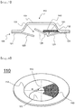
guide member 140, which extends toward the center of the cap plate, is attached to an outercircumferential side 112 of thecap plate 110, which is located under a protrudingportion 111 of thecap plate 110. Theguide member 140 contacts a portion of theflat portion 125 that has moved toward the cap plate such that theflat portion 125 has an inclined surface with respect to the ground. That is, the lower part of the inclined surface is located at the lower surface of theguide member 140, and the upper part of the inclined surface is located so as to be opposite the lower surface of the guide member. As a result, gas may be exhausted through aspace 101 defined between theflat portion 125, which is in an inclined state, and theinclined portion 123. Consequently, it is possible to form a gas exhaust path at the circumference of the flat portion in all directions, whereby it is possible to rapidly and safely exhaust gas. -
FIG. 8 is a bottom view of the cap plate shown inFIG. 3 . - Referring to
FIG. 8 , the lower surface of thecap plate 110 is defined by the outercircumferential side 112, which has a planar radius greater than the planar radius of the protrudingportion 111 of thecap plate 110, and theguide member 140, which extends toward the center of the cap plate, is attached to the outercircumferential side 111. - The
guide member 140 is shown as being formed in a fan shape, the apex of which has been removed. However, the present invention is not limited thereto. The guide member may be formed in a bar shape, a linear shape, or a polygonal shape. - The width W of the guide member has a range of 0.3 R to 1 R based on the radius R of the lower surface of the protruding portion of the cap plate, and the guide member may be formed so as to have a central angle of 10 to 90 degrees based on the circumference of the outer
circumferential side 112, which is circular when viewed in a plan view and encompasses 360 degrees. - Since the cap assembly according to the present invention is configured such that the guide member is attached to the lower surface of the cap plate, as described above, a portion of the safety vent is prevented from moving upwards by the guide member and is inclined even when the portion of the safety vent ruptures and is separated from the remaining portion of the safety vent, whereby it is possible to rapidly and safely exhaust gas from the circumference of the separated portion of the safety vent in all directions.
- Although the preferred embodiments of the present invention have been disclosed for illustrative purposes, those skilled in the art will appreciate that various modifications, additions and substitutions are possible, without departing from the scope and spirit of the invention as disclosed in the accompanying claims.
- As is apparent from the above description, the cap assembly according to the present invention is configured such that the guide member is attached to the inside of the cap plate in order to prevent the escape of the safety vent, which ruptures in order to exhaust gas when the interior pressure of the battery increases, whereby the ruptured portion of the safety vent is completely separated from the remaining portion of the safety vent. Consequently, it is possible to secure a wide gas exhaust path, and it is also possible to prevent the ruptured portion of the safety vent from colliding with the cap plate.
- In addition, it is possible to omit a process of forming a fixed portion, such as welding, in order to prevent the safety vent from being completely separated while rupturing, whereby it is possible to simplify the process of manufacturing the battery cell.
Claims (13)
- A cap assembly loaded on an open upper end part of a cylindrical can of a battery, the battery being configured to have a structure in which an electrode assembly is mounted in the cylindrical can, the cap assembly comprising:a safety vent configured to rupture in order to exhaust gas when an interior pressure of the battery increases;an upward-protrusion type cap plate loaded on an upper part of the safety vent, the cap plate being provided with a through-opening, through which gas is exhausted;a current interrupt member attached to a lower end of the safety vent for interrupting electric current when the interior pressure of the battery increases; anda guide member attached to an inside of the cap plate for preventing escape of a ruptured portion of the safety vent, which is ruptured as a result of an increase in the interior pressure of the battery.
- The cap assembly according to claim 1, wherein the guide member functions to prevent upward movement of a portion of the safety vent, which is separated from a remaining portion of the safety vent when the interior pressure of the battery increases, toward the cap plate.
- The cap assembly according to claim 1, wherein
the safety vent comprises a first bent portion bent downwards from an outer circumferential side thereof, an inclined portion extending downwards from the first bent portion, and a second bent portion bent horizontally from the inclined portion toward a center thereof, and
a notch for inducing rupture of the safety vent when the interior pressure of the battery increases is formed in the second bent portion of the first bent portion and the second bent portion. - The cap assembly according to claim 1, wherein the current interrupt member is provided at a center thereof with a protruding portion attached to a lower end of the safety vent so as to protrude upwards, and is also provided with two or more through-openings, through which gas is exhausted.
- The cap assembly according to claim 4, wherein the through-openings are formed in a radially symmetrical arrangement about a center of the current interrupt member while having an arc shape.
- The cap assembly according to claim 3, wherein the first bent portion is formed as a notch having a shape of a closed curve.
- The cap assembly according to claim 1, wherein the guide member extends from an outer circumferential side of a lower surface of a protruding portion of the cap plate toward a center of the cap plate.
- The cap assembly according to claim 1, wherein the guide member has a width equivalent to a range of 0.3 R to 1 R based on a radius (R) of a lower surface of a protruding portion of the cap plate.
- The cap assembly according to claim 1, wherein the guide member has a central angle of 10 to 90 degrees based on a planar circle having a lower surface of a protruding portion of the cap plate as an outer circumferential side thereof.
- The cap assembly according to claim 3, wherein the safety vent is configured such that, when the interior pressure of the battery increases, the notch formed in the second bent portion is broken, whereby a flat portion, which is partitioned from the inclined portion based on the second bent portion, is separated from the inclined portion.
- The cap assembly according to claim 10, wherein the separated flat portion is inclined so as to have an inclined surface with respect to a ground in order to form a gas exhaust path.
- The cap assembly according to claim 11, wherein a lower part of the inclined surface is located at a lower surface of the guide member, and an upper part of the inclined surface is located so as to be opposite the lower surface of the guide member.
- A cylindrical battery cell comprising a cap assembly according to any one of claims 1 to 12.
Applications Claiming Priority (2)
| Application Number | Priority Date | Filing Date | Title |
|---|---|---|---|
| KR1020170036732A KR102263423B1 (en) | 2017-03-23 | 2017-03-23 | Cap Assembly Comprising Guide Member for Preventing Detachment of Safety Vent |
| PCT/KR2018/003397 WO2018174621A2 (en) | 2017-03-23 | 2018-03-22 | Cap assembly comprising guide member for preventing escape of safety vent |
Publications (3)
| Publication Number | Publication Date |
|---|---|
| EP3565027A2 true EP3565027A2 (en) | 2019-11-06 |
| EP3565027A4 EP3565027A4 (en) | 2020-01-08 |
| EP3565027B1 EP3565027B1 (en) | 2023-09-13 |
Family
ID=63586428
Family Applications (1)
| Application Number | Title | Priority Date | Filing Date |
|---|---|---|---|
| EP18770229.5A Active EP3565027B1 (en) | 2017-03-23 | 2018-03-22 | Cap assembly comprising guide member for preventing escape of safety vent |
Country Status (9)
| Country | Link |
|---|---|
| US (1) | US11024922B2 (en) |
| EP (1) | EP3565027B1 (en) |
| JP (1) | JP6965492B2 (en) |
| KR (1) | KR102263423B1 (en) |
| CN (1) | CN110235276B (en) |
| ES (1) | ES2959765T3 (en) |
| HU (1) | HUE063861T2 (en) |
| PL (1) | PL3565027T3 (en) |
| WO (1) | WO2018174621A2 (en) |
Families Citing this family (7)
| Publication number | Priority date | Publication date | Assignee | Title |
|---|---|---|---|---|
| US10673038B2 (en) | 2018-03-23 | 2020-06-02 | Chongqing Jinkang New Energy Vehicle Co., Ltd. | Battery cells for battery packs in electric vehicles |
| KR102754505B1 (en) | 2019-08-16 | 2025-01-13 | 주식회사 엘지에너지솔루션 | Cylindrical battery |
| US20230027470A1 (en) * | 2019-12-13 | 2023-01-26 | Panasonic Intellectual Property Management Co., Ltd. | Sealed battery |
| US12525671B2 (en) | 2023-06-30 | 2026-01-13 | Rivian Ip Holdings, Llc | Battery welds |
| US12471245B2 (en) | 2023-06-30 | 2025-11-11 | Rivian Ip Holdings, Llc | Cold plate |
| US12542330B2 (en) | 2023-06-30 | 2026-02-03 | Rivian Ip Holdings, Llc | Battery subassembly with potting material |
| KR20250144579A (en) * | 2024-03-27 | 2025-10-13 | 삼성에스디아이 주식회사 | Secondary battery |
Family Cites Families (33)
| Publication number | Priority date | Publication date | Assignee | Title |
|---|---|---|---|---|
| BE625069A (en) * | 1961-12-15 | |||
| US5853912A (en) * | 1996-07-10 | 1998-12-29 | Saft America, Inc. | Lithium ion electrochemical cell with safety valve electrical disconnect |
| JPH10247483A (en) | 1997-03-04 | 1998-09-14 | Mitsubishi Cable Ind Ltd | Safety structure of sealed battery |
| JP2001216943A (en) | 2000-02-03 | 2001-08-10 | Matsushita Electric Ind Co Ltd | Sealing structure for sealed batteries and sealed batteries |
| KR100528915B1 (en) | 2003-05-26 | 2005-11-16 | 삼성에스디아이 주식회사 | Secondary battery |
| KR100578804B1 (en) | 2004-03-29 | 2006-05-11 | 삼성에스디아이 주식회사 | Cap assembly and secondary battery having same |
| KR100637434B1 (en) * | 2004-05-19 | 2006-10-20 | 삼성에스디아이 주식회사 | Secondary and secondary battery cap assemblies and safety valves used therein |
| KR100614377B1 (en) | 2004-11-15 | 2006-08-21 | 삼성에스디아이 주식회사 | Lithium secondary battery |
| KR100878701B1 (en) * | 2006-03-13 | 2009-01-14 | 주식회사 엘지화학 | High rate charge and discharge cylindrical secondary battery |
| US8017266B2 (en) | 2006-09-25 | 2011-09-13 | Panasonic Corporation | Battery having positive temperature coefficient element |
| JP2008084845A (en) * | 2006-09-25 | 2008-04-10 | Matsushita Electric Ind Co Ltd | Cylindrical primary battery |
| KR100997043B1 (en) * | 2006-10-23 | 2010-11-29 | 주식회사 엘지화학 | Cap assembly with improved safety by leakage leakage and cylindrical secondary battery containing same |
| KR101396703B1 (en) | 2008-03-05 | 2014-05-19 | 삼성에스디아이 주식회사 | Apparatus of Removing Gas and Cylinder type Secondary Battery using the same |
| KR100966549B1 (en) * | 2008-10-14 | 2010-06-29 | 주식회사 엘지화학 | Cap assembly with improved safety and cylindrical secondary battery containing same |
| US8486546B2 (en) * | 2008-12-01 | 2013-07-16 | Samsung Sdi Co., Ltd. | Cap assembly and secondary battery using the same with notched vent member |
| KR101094937B1 (en) * | 2009-02-16 | 2011-12-15 | 삼성에스디아이 주식회사 | Cylindrical secondary battery |
| US8241772B2 (en) * | 2009-06-12 | 2012-08-14 | Tesla Motors, Inc. | Integrated battery pressure relief and terminal isolation system |
| KR101184970B1 (en) * | 2009-10-13 | 2012-10-02 | 주식회사 엘지화학 | Cap assembly characterized by preventing gasket from drooping, and cylinderical secondary battery comprising the same |
| KR101097101B1 (en) * | 2009-12-29 | 2011-12-22 | 주식회사 루트제이드 | Secondary battery having exploding prevention device |
| US8597809B2 (en) * | 2010-02-18 | 2013-12-03 | Samsung Sdi Co., Ltd. | Rechargeable battery |
| KR101279994B1 (en) * | 2010-10-15 | 2013-07-05 | 주식회사 엘지화학 | Cap Assembly of Structure Having Safety Element on Electrode Lead and Cylindrical Battery Employed with the Same |
| KR101184403B1 (en) * | 2010-10-21 | 2012-09-19 | 주식회사 엘지화학 | Cap assembly and secondary battery using the same |
| KR101254174B1 (en) * | 2011-03-08 | 2013-04-18 | 주식회사 엘지화학 | Cylindrical Secondary Battery of Improved Safety |
| JP5110671B2 (en) * | 2011-03-09 | 2012-12-26 | パナソニック株式会社 | Cylindrical battery |
| KR101292534B1 (en) | 2011-09-27 | 2013-08-09 | 상신이디피(주) | The safety vent on cylindrical can of secondary battery |
| KR101916964B1 (en) | 2012-08-08 | 2018-11-08 | 삼성에스디아이 주식회사 | Secondary battery |
| KR101523064B1 (en) * | 2013-02-26 | 2015-05-26 | 주식회사 엘지화학 | Cap assembly and secondary battery including the same |
| KR101826879B1 (en) | 2013-11-04 | 2018-02-07 | 주식회사 엘지화학 | Current interrupting device and Secondary battery using the same |
| JP6731580B2 (en) * | 2014-05-30 | 2020-07-29 | パナソニックIpマネジメント株式会社 | Cylindrical lithium-ion secondary battery |
| KR101772266B1 (en) * | 2014-09-19 | 2017-08-30 | 신흥에스이씨주식회사 | Cap assembly with heat-controlled circuit breaker for a secondary battery and the battery |
| KR20160037518A (en) | 2014-09-29 | 2016-04-06 | 주식회사 엘지화학 | Cylindrical Battery Including Pressuring Part and Manufacturing Method for the Same |
| KR20160074057A (en) * | 2014-12-18 | 2016-06-28 | 주식회사 하나플라텍 | Improved structure for the secondary cell battery |
| KR102493946B1 (en) * | 2015-12-24 | 2023-01-31 | 삼성에스디아이 주식회사 | Secondary battery |
-
2017
- 2017-03-23 KR KR1020170036732A patent/KR102263423B1/en active Active
-
2018
- 2018-03-22 WO PCT/KR2018/003397 patent/WO2018174621A2/en not_active Ceased
- 2018-03-22 HU HUE18770229A patent/HUE063861T2/en unknown
- 2018-03-22 ES ES18770229T patent/ES2959765T3/en active Active
- 2018-03-22 US US16/465,364 patent/US11024922B2/en active Active
- 2018-03-22 JP JP2019526522A patent/JP6965492B2/en active Active
- 2018-03-22 EP EP18770229.5A patent/EP3565027B1/en active Active
- 2018-03-22 PL PL18770229.5T patent/PL3565027T3/en unknown
- 2018-03-22 CN CN201880008671.9A patent/CN110235276B/en active Active
Also Published As
| Publication number | Publication date |
|---|---|
| KR102263423B1 (en) | 2021-06-11 |
| WO2018174621A3 (en) | 2019-01-03 |
| KR20180107874A (en) | 2018-10-04 |
| JP6965492B2 (en) | 2021-11-10 |
| EP3565027B1 (en) | 2023-09-13 |
| CN110235276B (en) | 2021-11-26 |
| WO2018174621A2 (en) | 2018-09-27 |
| JP2020514947A (en) | 2020-05-21 |
| EP3565027A4 (en) | 2020-01-08 |
| HUE063861T2 (en) | 2024-02-28 |
| ES2959765T3 (en) | 2024-02-28 |
| CN110235276A (en) | 2019-09-13 |
| US20190393462A1 (en) | 2019-12-26 |
| US11024922B2 (en) | 2021-06-01 |
| PL3565027T3 (en) | 2024-01-22 |
Similar Documents
| Publication | Publication Date | Title |
|---|---|---|
| EP3565027B1 (en) | Cap assembly comprising guide member for preventing escape of safety vent | |
| US10490792B2 (en) | Cap assembly for secondary battery | |
| CA2738303C (en) | Cap assembly with improved stability and cylindrical secondary battery including the same | |
| KR101683210B1 (en) | Rechargeable battery | |
| KR101326069B1 (en) | Cap Assembly of Improved Productivity and Cylindrical Battery Cell Employed with the Same | |
| KR101310731B1 (en) | Secondary battery | |
| KR20160043725A (en) | cylindrical secondary battery comprise notch | |
| JP7388753B2 (en) | cylindrical battery | |
| KR20130115594A (en) | Rechargeable battery | |
| KR102392645B1 (en) | Cap Assembly Comprising Magnet | |
| KR101175008B1 (en) | Cylinderical Rechargeable Battery | |
| KR102522701B1 (en) | The Secondary Battery | |
| EP4145611A1 (en) | Secondary battery | |
| KR101293208B1 (en) | Cap assembly for secondary battery | |
| KR20130063206A (en) | Secondary battery and battery pack including the same | |
| KR20150021732A (en) | Cap Assembly Having Safety Vent with Notch | |
| KR101733741B1 (en) | Rechargeable battery having connecting member | |
| KR20150051516A (en) | Cap assembly and secondary battery comprising the same | |
| KR20140082270A (en) | Secondary battery and battery pack including the same | |
| KR20200020334A (en) | Cylindrical Secondary Battery Including Top Openable Structure | |
| KR20210048924A (en) | Secondary battery and battery pack including the same | |
| KR20220018769A (en) | Rechargeable battery | |
| KR20170022443A (en) | Rechargeable battery | |
| KR20170053387A (en) | Beading-less cap assembly with inverse vent structure |
Legal Events
| Date | Code | Title | Description |
|---|---|---|---|
| STAA | Information on the status of an ep patent application or granted ep patent |
Free format text: STATUS: THE INTERNATIONAL PUBLICATION HAS BEEN MADE |
|
| PUAI | Public reference made under article 153(3) epc to a published international application that has entered the european phase |
Free format text: ORIGINAL CODE: 0009012 |
|
| STAA | Information on the status of an ep patent application or granted ep patent |
Free format text: STATUS: REQUEST FOR EXAMINATION WAS MADE |
|
| 17P | Request for examination filed |
Effective date: 20190801 |
|
| AK | Designated contracting states |
Kind code of ref document: A2 Designated state(s): AL AT BE BG CH CY CZ DE DK EE ES FI FR GB GR HR HU IE IS IT LI LT LU LV MC MK MT NL NO PL PT RO RS SE SI SK SM TR |
|
| AX | Request for extension of the european patent |
Extension state: BA ME |
|
| A4 | Supplementary search report drawn up and despatched |
Effective date: 20191205 |
|
| RIC1 | Information provided on ipc code assigned before grant |
Ipc: H01M 10/04 20060101ALI20191130BHEP Ipc: H01M 2/04 20060101ALI20191130BHEP Ipc: H01M 2/12 20060101AFI20191130BHEP Ipc: H01M 2/02 20060101ALI20191130BHEP Ipc: H01M 2/34 20060101ALI20191130BHEP |
|
| DAV | Request for validation of the european patent (deleted) | ||
| DAX | Request for extension of the european patent (deleted) | ||
| RAP1 | Party data changed (applicant data changed or rights of an application transferred) |
Owner name: LG ENERGY SOLUTION LTD. |
|
| RAP3 | Party data changed (applicant data changed or rights of an application transferred) |
Owner name: LG ENERGY SOLUTION, LTD. |
|
| REG | Reference to a national code |
Ref country code: DE Ref legal event code: R079 Free format text: PREVIOUS MAIN CLASS: H01M0002120000 Ipc: H01M0010040000 Ref document number: 602018057530 Country of ref document: DE |
|
| RIC1 | Information provided on ipc code assigned before grant |
Ipc: H01M 10/04 20060101AFI20230301BHEP |
|
| GRAP | Despatch of communication of intention to grant a patent |
Free format text: ORIGINAL CODE: EPIDOSNIGR1 |
|
| STAA | Information on the status of an ep patent application or granted ep patent |
Free format text: STATUS: GRANT OF PATENT IS INTENDED |
|
| INTG | Intention to grant announced |
Effective date: 20230516 |
|
| P01 | Opt-out of the competence of the unified patent court (upc) registered |
Effective date: 20230530 |
|
| GRAS | Grant fee paid |
Free format text: ORIGINAL CODE: EPIDOSNIGR3 |
|
| GRAA | (expected) grant |
Free format text: ORIGINAL CODE: 0009210 |
|
| STAA | Information on the status of an ep patent application or granted ep patent |
Free format text: STATUS: THE PATENT HAS BEEN GRANTED |
|
| AK | Designated contracting states |
Kind code of ref document: B1 Designated state(s): AL AT BE BG CH CY CZ DE DK EE ES FI FR GB GR HR HU IE IS IT LI LT LU LV MC MK MT NL NO PL PT RO RS SE SI SK SM TR |
|
| REG | Reference to a national code |
Ref country code: CH Ref legal event code: EP |
|
| REG | Reference to a national code |
Ref country code: DE Ref legal event code: R096 Ref document number: 602018057530 Country of ref document: DE |
|
| REG | Reference to a national code |
Ref country code: IE Ref legal event code: FG4D |
|
| REG | Reference to a national code |
Ref country code: SE Ref legal event code: TRGR |
|
| REG | Reference to a national code |
Ref country code: LT Ref legal event code: MG9D |
|
| REG | Reference to a national code |
Ref country code: NL Ref legal event code: MP Effective date: 20230913 |
|
| PG25 | Lapsed in a contracting state [announced via postgrant information from national office to epo] |
Ref country code: GR Free format text: LAPSE BECAUSE OF FAILURE TO SUBMIT A TRANSLATION OF THE DESCRIPTION OR TO PAY THE FEE WITHIN THE PRESCRIBED TIME-LIMIT Effective date: 20231214 |
|
| PG25 | Lapsed in a contracting state [announced via postgrant information from national office to epo] |
Ref country code: RS Free format text: LAPSE BECAUSE OF FAILURE TO SUBMIT A TRANSLATION OF THE DESCRIPTION OR TO PAY THE FEE WITHIN THE PRESCRIBED TIME-LIMIT Effective date: 20230913 Ref country code: NO Free format text: LAPSE BECAUSE OF FAILURE TO SUBMIT A TRANSLATION OF THE DESCRIPTION OR TO PAY THE FEE WITHIN THE PRESCRIBED TIME-LIMIT Effective date: 20231213 Ref country code: LV Free format text: LAPSE BECAUSE OF FAILURE TO SUBMIT A TRANSLATION OF THE DESCRIPTION OR TO PAY THE FEE WITHIN THE PRESCRIBED TIME-LIMIT Effective date: 20230913 Ref country code: LT Free format text: LAPSE BECAUSE OF FAILURE TO SUBMIT A TRANSLATION OF THE DESCRIPTION OR TO PAY THE FEE WITHIN THE PRESCRIBED TIME-LIMIT Effective date: 20230913 Ref country code: HR Free format text: LAPSE BECAUSE OF FAILURE TO SUBMIT A TRANSLATION OF THE DESCRIPTION OR TO PAY THE FEE WITHIN THE PRESCRIBED TIME-LIMIT Effective date: 20230913 Ref country code: GR Free format text: LAPSE BECAUSE OF FAILURE TO SUBMIT A TRANSLATION OF THE DESCRIPTION OR TO PAY THE FEE WITHIN THE PRESCRIBED TIME-LIMIT Effective date: 20231214 Ref country code: FI Free format text: LAPSE BECAUSE OF FAILURE TO SUBMIT A TRANSLATION OF THE DESCRIPTION OR TO PAY THE FEE WITHIN THE PRESCRIBED TIME-LIMIT Effective date: 20230913 |
|
| REG | Reference to a national code |
Ref country code: AT Ref legal event code: MK05 Ref document number: 1612211 Country of ref document: AT Kind code of ref document: T Effective date: 20230913 |
|
| REG | Reference to a national code |
Ref country code: HU Ref legal event code: AG4A Ref document number: E063861 Country of ref document: HU Ref country code: ES Ref legal event code: FG2A Ref document number: 2959765 Country of ref document: ES Kind code of ref document: T3 Effective date: 20240228 |
|
| PG25 | Lapsed in a contracting state [announced via postgrant information from national office to epo] |
Ref country code: NL Free format text: LAPSE BECAUSE OF FAILURE TO SUBMIT A TRANSLATION OF THE DESCRIPTION OR TO PAY THE FEE WITHIN THE PRESCRIBED TIME-LIMIT Effective date: 20230913 |
|
| PG25 | Lapsed in a contracting state [announced via postgrant information from national office to epo] |
Ref country code: IS Free format text: LAPSE BECAUSE OF FAILURE TO SUBMIT A TRANSLATION OF THE DESCRIPTION OR TO PAY THE FEE WITHIN THE PRESCRIBED TIME-LIMIT Effective date: 20240113 |
|
| PG25 | Lapsed in a contracting state [announced via postgrant information from national office to epo] |
Ref country code: AT Free format text: LAPSE BECAUSE OF FAILURE TO SUBMIT A TRANSLATION OF THE DESCRIPTION OR TO PAY THE FEE WITHIN THE PRESCRIBED TIME-LIMIT Effective date: 20230913 |
|
| PG25 | Lapsed in a contracting state [announced via postgrant information from national office to epo] |
Ref country code: SM Free format text: LAPSE BECAUSE OF FAILURE TO SUBMIT A TRANSLATION OF THE DESCRIPTION OR TO PAY THE FEE WITHIN THE PRESCRIBED TIME-LIMIT Effective date: 20230913 Ref country code: RO Free format text: LAPSE BECAUSE OF FAILURE TO SUBMIT A TRANSLATION OF THE DESCRIPTION OR TO PAY THE FEE WITHIN THE PRESCRIBED TIME-LIMIT Effective date: 20230913 Ref country code: IS Free format text: LAPSE BECAUSE OF FAILURE TO SUBMIT A TRANSLATION OF THE DESCRIPTION OR TO PAY THE FEE WITHIN THE PRESCRIBED TIME-LIMIT Effective date: 20240113 Ref country code: EE Free format text: LAPSE BECAUSE OF FAILURE TO SUBMIT A TRANSLATION OF THE DESCRIPTION OR TO PAY THE FEE WITHIN THE PRESCRIBED TIME-LIMIT Effective date: 20230913 Ref country code: CZ Free format text: LAPSE BECAUSE OF FAILURE TO SUBMIT A TRANSLATION OF THE DESCRIPTION OR TO PAY THE FEE WITHIN THE PRESCRIBED TIME-LIMIT Effective date: 20230913 Ref country code: AT Free format text: LAPSE BECAUSE OF FAILURE TO SUBMIT A TRANSLATION OF THE DESCRIPTION OR TO PAY THE FEE WITHIN THE PRESCRIBED TIME-LIMIT Effective date: 20230913 Ref country code: SK Free format text: LAPSE BECAUSE OF FAILURE TO SUBMIT A TRANSLATION OF THE DESCRIPTION OR TO PAY THE FEE WITHIN THE PRESCRIBED TIME-LIMIT Effective date: 20230913 Ref country code: PT Free format text: LAPSE BECAUSE OF FAILURE TO SUBMIT A TRANSLATION OF THE DESCRIPTION OR TO PAY THE FEE WITHIN THE PRESCRIBED TIME-LIMIT Effective date: 20240115 |
|
| PG25 | Lapsed in a contracting state [announced via postgrant information from national office to epo] |
Ref country code: IT Free format text: LAPSE BECAUSE OF FAILURE TO SUBMIT A TRANSLATION OF THE DESCRIPTION OR TO PAY THE FEE WITHIN THE PRESCRIBED TIME-LIMIT Effective date: 20230913 |
|
| REG | Reference to a national code |
Ref country code: DE Ref legal event code: R097 Ref document number: 602018057530 Country of ref document: DE |
|
| PG25 | Lapsed in a contracting state [announced via postgrant information from national office to epo] |
Ref country code: DK Free format text: LAPSE BECAUSE OF FAILURE TO SUBMIT A TRANSLATION OF THE DESCRIPTION OR TO PAY THE FEE WITHIN THE PRESCRIBED TIME-LIMIT Effective date: 20230913 |
|
| PLBE | No opposition filed within time limit |
Free format text: ORIGINAL CODE: 0009261 |
|
| STAA | Information on the status of an ep patent application or granted ep patent |
Free format text: STATUS: NO OPPOSITION FILED WITHIN TIME LIMIT |
|
| PG25 | Lapsed in a contracting state [announced via postgrant information from national office to epo] |
Ref country code: DK Free format text: LAPSE BECAUSE OF FAILURE TO SUBMIT A TRANSLATION OF THE DESCRIPTION OR TO PAY THE FEE WITHIN THE PRESCRIBED TIME-LIMIT Effective date: 20230913 |
|
| 26N | No opposition filed |
Effective date: 20240614 |
|
| PG25 | Lapsed in a contracting state [announced via postgrant information from national office to epo] |
Ref country code: SI Free format text: LAPSE BECAUSE OF FAILURE TO SUBMIT A TRANSLATION OF THE DESCRIPTION OR TO PAY THE FEE WITHIN THE PRESCRIBED TIME-LIMIT Effective date: 20230913 |
|
| PG25 | Lapsed in a contracting state [announced via postgrant information from national office to epo] |
Ref country code: SI Free format text: LAPSE BECAUSE OF FAILURE TO SUBMIT A TRANSLATION OF THE DESCRIPTION OR TO PAY THE FEE WITHIN THE PRESCRIBED TIME-LIMIT Effective date: 20230913 |
|
| REG | Reference to a national code |
Ref country code: CH Ref legal event code: PL |
|
| PG25 | Lapsed in a contracting state [announced via postgrant information from national office to epo] |
Ref country code: BG Free format text: LAPSE BECAUSE OF FAILURE TO SUBMIT A TRANSLATION OF THE DESCRIPTION OR TO PAY THE FEE WITHIN THE PRESCRIBED TIME-LIMIT Effective date: 20230913 |
|
| PG25 | Lapsed in a contracting state [announced via postgrant information from national office to epo] |
Ref country code: LU Free format text: LAPSE BECAUSE OF NON-PAYMENT OF DUE FEES Effective date: 20240322 |
|
| PG25 | Lapsed in a contracting state [announced via postgrant information from national office to epo] |
Ref country code: MC Free format text: LAPSE BECAUSE OF FAILURE TO SUBMIT A TRANSLATION OF THE DESCRIPTION OR TO PAY THE FEE WITHIN THE PRESCRIBED TIME-LIMIT Effective date: 20230913 |
|
| PG25 | Lapsed in a contracting state [announced via postgrant information from national office to epo] |
Ref country code: MC Free format text: LAPSE BECAUSE OF FAILURE TO SUBMIT A TRANSLATION OF THE DESCRIPTION OR TO PAY THE FEE WITHIN THE PRESCRIBED TIME-LIMIT Effective date: 20230913 Ref country code: LU Free format text: LAPSE BECAUSE OF NON-PAYMENT OF DUE FEES Effective date: 20240322 Ref country code: BG Free format text: LAPSE BECAUSE OF FAILURE TO SUBMIT A TRANSLATION OF THE DESCRIPTION OR TO PAY THE FEE WITHIN THE PRESCRIBED TIME-LIMIT Effective date: 20230913 |
|
| REG | Reference to a national code |
Ref country code: BE Ref legal event code: MM Effective date: 20240331 |
|
| PG25 | Lapsed in a contracting state [announced via postgrant information from national office to epo] |
Ref country code: BE Free format text: LAPSE BECAUSE OF NON-PAYMENT OF DUE FEES Effective date: 20240331 |
|
| PG25 | Lapsed in a contracting state [announced via postgrant information from national office to epo] |
Ref country code: IE Free format text: LAPSE BECAUSE OF NON-PAYMENT OF DUE FEES Effective date: 20240322 |
|
| PG25 | Lapsed in a contracting state [announced via postgrant information from national office to epo] |
Ref country code: IE Free format text: LAPSE BECAUSE OF NON-PAYMENT OF DUE FEES Effective date: 20240322 Ref country code: BE Free format text: LAPSE BECAUSE OF NON-PAYMENT OF DUE FEES Effective date: 20240331 Ref country code: CH Free format text: LAPSE BECAUSE OF NON-PAYMENT OF DUE FEES Effective date: 20240331 |
|
| PGFP | Annual fee paid to national office [announced via postgrant information from national office to epo] |
Ref country code: ES Payment date: 20250408 Year of fee payment: 8 |
|
| PG25 | Lapsed in a contracting state [announced via postgrant information from national office to epo] |
Ref country code: CY Free format text: LAPSE BECAUSE OF FAILURE TO SUBMIT A TRANSLATION OF THE DESCRIPTION OR TO PAY THE FEE WITHIN THE PRESCRIBED TIME-LIMIT; INVALID AB INITIO Effective date: 20180322 |
|
| PG25 | Lapsed in a contracting state [announced via postgrant information from national office to epo] |
Ref country code: TR Free format text: LAPSE BECAUSE OF FAILURE TO SUBMIT A TRANSLATION OF THE DESCRIPTION OR TO PAY THE FEE WITHIN THE PRESCRIBED TIME-LIMIT Effective date: 20230913 |
|
| PGFP | Annual fee paid to national office [announced via postgrant information from national office to epo] |
Ref country code: SE Payment date: 20260223 Year of fee payment: 9 |
|
| PGFP | Annual fee paid to national office [announced via postgrant information from national office to epo] |
Ref country code: GB Payment date: 20260224 Year of fee payment: 9 |
|
| PGFP | Annual fee paid to national office [announced via postgrant information from national office to epo] |
Ref country code: DE Payment date: 20260220 Year of fee payment: 9 |
|
| PGFP | Annual fee paid to national office [announced via postgrant information from national office to epo] |
Ref country code: HU Payment date: 20260310 Year of fee payment: 9 |
|
| PGFP | Annual fee paid to national office [announced via postgrant information from national office to epo] |
Ref country code: FR Payment date: 20260224 Year of fee payment: 9 |
|
| PGFP | Annual fee paid to national office [announced via postgrant information from national office to epo] |
Ref country code: PL Payment date: 20260224 Year of fee payment: 9 |