EP3564970B1 - Single-core submarine cable - Google Patents
Single-core submarine cable Download PDFInfo
- Publication number
- EP3564970B1 EP3564970B1 EP17927143.2A EP17927143A EP3564970B1 EP 3564970 B1 EP3564970 B1 EP 3564970B1 EP 17927143 A EP17927143 A EP 17927143A EP 3564970 B1 EP3564970 B1 EP 3564970B1
- Authority
- EP
- European Patent Office
- Prior art keywords
- layer
- single core
- submarine cable
- metal wires
- cable
- Prior art date
- Legal status (The legal status is an assumption and is not a legal conclusion. Google has not performed a legal analysis and makes no representation as to the accuracy of the status listed.)
- Active
Links
Images


Classifications
-
- H—ELECTRICITY
- H01—ELECTRIC ELEMENTS
- H01B—CABLES; CONDUCTORS; INSULATORS; SELECTION OF MATERIALS FOR THEIR CONDUCTIVE, INSULATING OR DIELECTRIC PROPERTIES
- H01B7/00—Insulated conductors or cables characterised by their form
- H01B7/14—Submarine cables
-
- G—PHYSICS
- G02—OPTICS
- G02B—OPTICAL ELEMENTS, SYSTEMS OR APPARATUS
- G02B6/00—Light guides; Structural details of arrangements comprising light guides and other optical elements, e.g. couplings
- G02B6/44—Mechanical structures for providing tensile strength and external protection for fibres, e.g. optical transmission cables
- G02B6/4401—Optical cables
- G02B6/4415—Cables for special applications
- G02B6/4416—Heterogeneous cables
-
- G—PHYSICS
- G02—OPTICS
- G02B—OPTICAL ELEMENTS, SYSTEMS OR APPARATUS
- G02B6/00—Light guides; Structural details of arrangements comprising light guides and other optical elements, e.g. couplings
- G02B6/44—Mechanical structures for providing tensile strength and external protection for fibres, e.g. optical transmission cables
- G02B6/4401—Optical cables
- G02B6/4415—Cables for special applications
- G02B6/4427—Pressure resistant cables, e.g. undersea cables
-
- G—PHYSICS
- G02—OPTICS
- G02B—OPTICAL ELEMENTS, SYSTEMS OR APPARATUS
- G02B6/00—Light guides; Structural details of arrangements comprising light guides and other optical elements, e.g. couplings
- G02B6/44—Mechanical structures for providing tensile strength and external protection for fibres, e.g. optical transmission cables
- G02B6/4401—Optical cables
- G02B6/4429—Means specially adapted for strengthening or protecting the cables
- G02B6/443—Protective covering
- G02B6/4432—Protective covering with fibre reinforcements
-
- H—ELECTRICITY
- H01—ELECTRIC ELEMENTS
- H01B—CABLES; CONDUCTORS; INSULATORS; SELECTION OF MATERIALS FOR THEIR CONDUCTIVE, INSULATING OR DIELECTRIC PROPERTIES
- H01B7/00—Insulated conductors or cables characterised by their form
- H01B7/17—Protection against damage caused by external factors, e.g. sheaths or armouring
- H01B7/18—Protection against damage caused by wear, mechanical force or pressure; Sheaths; Armouring
- H01B7/22—Metal wires or tapes, e.g. made of steel
-
- H—ELECTRICITY
- H01—ELECTRIC ELEMENTS
- H01B—CABLES; CONDUCTORS; INSULATORS; SELECTION OF MATERIALS FOR THEIR CONDUCTIVE, INSULATING OR DIELECTRIC PROPERTIES
- H01B7/00—Insulated conductors or cables characterised by their form
- H01B7/17—Protection against damage caused by external factors, e.g. sheaths or armouring
- H01B7/18—Protection against damage caused by wear, mechanical force or pressure; Sheaths; Armouring
- H01B7/22—Metal wires or tapes, e.g. made of steel
- H01B7/221—Longitudinally placed metal wires or tapes
- H01B7/225—Longitudinally placed metal wires or tapes forming part of an outer sheath
-
- H—ELECTRICITY
- H01—ELECTRIC ELEMENTS
- H01B—CABLES; CONDUCTORS; INSULATORS; SELECTION OF MATERIALS FOR THEIR CONDUCTIVE, INSULATING OR DIELECTRIC PROPERTIES
- H01B9/00—Power cables
- H01B9/005—Power cables including optical transmission elements
-
- H—ELECTRICITY
- H01—ELECTRIC ELEMENTS
- H01B—CABLES; CONDUCTORS; INSULATORS; SELECTION OF MATERIALS FOR THEIR CONDUCTIVE, INSULATING OR DIELECTRIC PROPERTIES
- H01B9/00—Power cables
- H01B9/02—Power cables with screens or conductive layers, e.g. for avoiding large potential gradients
-
- H—ELECTRICITY
- H01—ELECTRIC ELEMENTS
- H01B—CABLES; CONDUCTORS; INSULATORS; SELECTION OF MATERIALS FOR THEIR CONDUCTIVE, INSULATING OR DIELECTRIC PROPERTIES
- H01B9/00—Power cables
- H01B9/02—Power cables with screens or conductive layers, e.g. for avoiding large potential gradients
- H01B9/027—Power cables with screens or conductive layers, e.g. for avoiding large potential gradients composed of semi-conducting layers
Definitions
- the subject matter herein generally relates to a single core submarine cable.
- a single core submarine cable transmitting and distributing electric energy through a single conductor is convenient for line connection and equipment connection.
- Such cable can be used undersea, for supplying electrical power to coastal cities and transmitting power generated by offshore wind power.
- the reset route of a submarine cable is designed in multiple sections and is complex, the local undersea environment and working conditions will affect the carrying capacity of the cable. There are bottleneck sections in the reset route where the carrying capacity cannot meet the current requirements for which it is rated. As a result, one submarine cable cannot guarantee that every section of a route meets the requirement of current rating.
- Reducing electrical loss through armor is an effective way to improve the carrying capacity of a submarine cable.
- Common types of armor includes galvanized steel wire and copper wire, the galvanized steel wire armor has high resistance, large loss through armor, and low carrying capacity.
- Copper wire armor has low resistance and high corrosion resistance, but has mechanical strength lower than the galvanized steel wire armor, and is expensive.
- CN205789189U discloses a submarine cable a single core submarine power cable which includes a wire core, a shielding layer, an insulating layer, an insulator shielding layer, a lead sleeve, an inner protective layer, an armor layer, and an outer protective layer arranged from the inside to the outside.
- the armor layer is formed by twisting a plurality of metal wires.
- the armor is divided into a first armor layer for land and a second armor layer for underwater, an end of the first armor layer is butted with an end of the second armor layer to form an integrated armor layer.
- CN106094145A discloses a submarine optical cable which uses a fiber reinforced material and a galvanized steel wire material to form an armor layer. By adjusting a combination ratio of the fiber reinforced material and galvanized steel wire material, a weight of the submarine optical cable is adjustable.
- the present disclosure provides a single core submarine cable having the characteristics of adjustable carrying capacity, low loss through armor, high mechanical strength, and corrosion resistance.
- the invention is set out in the appended set of claims.
- an increase in the number of the first metal wires reduces the resistance of the armor, the loss through armor is reduced, and the carrying capacity is increased, so the carrying capacity of the cable in the bottleneck section will be sufficient to meet the requirements of rated currents.
- an increase of the number of the second metal wires improves the mechanical strength, and the cost is reduced.
- the carrying capacity of the single core submarine cable of the present disclosure can be controlled and adjusted, and meet the requirements of rated currents in the bottleneck section route.
- Each single core submarine cable can meet the requirements of the rated current in multi-section routes located in different areas and environments, and mechanical strength and cost are optimized.
- the single core submarine cable is very maneuverable, and construction is convenient. The amount of material used for the single core submarine cable is not significantly extra.
- single core submarine cable is labeled 100
- cable core is labeled 10
- inner protecting layer is labeled 20
- armor layer is labeled 30
- first metal wire is labeled 31
- second metal wire is labeled 32
- outer protecting layer is labeled 40
- conductor shielding layer is labeled 21
- insulation layer is labeled 22
- insulation shielding layer is labeled 23
- first protective layer is labeled 50
- water-resistant tape winding layer is labeled 51
- metal protective layer is labeled 52
- polyethylene protective layer is labeled 53
- lining layer is labeled 54
- filling protective layer is labeled 55
- fiber unit is labeled 56
- fiber is labeled 56-a
- water-resisting ointment is labeled 56-b
- stainless steel tube is labeled 56-c
- plastic protective layer is labeled 56-d.
- FIG. 1 illustrates a single core submarine cable 100.
- the cable 100 includes a cable core 10, an inner protecting layer 20 positioned outside of the cable core 10, and an armor layer 30 positioned outside of the inner protecting layer 20.
- the single core submarine cable 100 is used for underwater power transmission, for example, supplying power to coastal cities and transmitting power generated by offshore wind power.
- the armor layer 30 includes first metal wires 31 and second wires 32 with a constant sum of number. The number of the first and second metal wires is different at least between a first section and a second section.
- FIGS. 1 and 2 illustrate the cable core 10 being positioned at the center of the single core submarine cable 100.
- the cable core 10 includes a water-resistant conductor and a water-resistant filling material positioned in gaps of the water-resistant conductor.
- the water-resistant conductor is the carrier of electrical current in the single core submarine cable 100.
- the water-resistant filling material is gap filler material.
- the water-resistant filling material protects the water-resistant conductor.
- the water-resistant conductor is in the form of round compacted strand or shaped line.
- the water-resistant filling material is water-resistant tape, water-resistant powder, water-resistant yarn, water-resistant glue, or a combination thereof.
- FIGS. 2 and 3 illustrate that the inner protecting layer 20 is positioned outside of the cable core 10.
- the inner protecting layer 20 acts as shielding, as insulation, and as protection for the cable core 10.
- the inner protecting layer 20 includes a conductor shielding layer 21, an insulation layer 22, an insulation shielding layer 23, and a first protective layer 50 arranged in that order from the inside to the outside.
- the conductor shielding layer 21 is formed by wrapping a semi-conductive binding water-resistant tape and extruding an ultra-smooth semi-conductive shielding material.
- the insulation layer 22 is formed on the conductor shielding layer 21 by an even extrusion of the ultra-clean cross-linked polyethylene material.
- the insulation shielding layer 23 is formed on the insulation layer 22 by directly extruding the ultra-smooth semi-conductive shielding material.
- the first protective layer 50 includes a water-resistant tape winding layer 51, a metal protective layer 52, a polyethylene protective layer 53, and a lining layer 54 arranged in that order from the inside to the outside.
- the water-resistant tape winding layer 51 is formed on the insulation shielding layer 23 by overlapping in wrapping semi-conducting resistant tape.
- the metal protective layer 52 is a continuous sealing structure, formed on the water-resistant tape winding layer 51 by directly extruding the lead alloy material.
- the polyethylene protective layer 53 is formed on the metal protective layer 52 by directly extruding semi-conductive polyethylene or insulating polyethylene thermoplastic sheathing material.
- the lining layer 54 is of high strength polypropylene fiber rope winding structure with a diameter of 2 ⁇ 4 mm.
- FIG. 3 and 4 illustrate that the single core submarine cable 100 includes a filling protective layer 55 and a fiber unit 56.
- the single core submarine cable 100 is an optoelectric composite cable.
- the filling protective layer 55 is positioned between the polyethylene protective layer 53 and the lining layer 54.
- the fiber unit 56 is positioned in gaps of the filling protective layer 55.
- the filling protective layer 55 is a cylinder formed by the continuous extrusion of high strength thermoplastic material, for filling and protecting the fiber unit 56.
- the fiber unit 56 carries optical signals in the single core marine cable 100.
- the fiber unit 56 includes a fiber 56-a, a water-resisting ointment 56-b, a stainless steel tube 56-c, and a plastic protective layer 56-d.
- the single core marine cable 100 includes two groups of fiber units 56. Each fiber unit 56 group includes 36 fibers.
- the single core marine cable 100 includes one, three, or four groups of fiber units. Each group of fiber units 56 includes 1 ⁇ 36 fibers. The single core marine cable 100 may not include the fiber unit 56 and the filling protecting layer 55.
- the rated current required by the single core submarine cable 100 is 700A
- the carrying capacity of the steel wire armored cable under certain routing conditions is 650A
- the carrying capacity of the copper wire armored cable under the same conditions is 850A.
- the single core submarine cable 100 combines two kinds of metal wires to improve the characteristics of the armor. By calculating the diameter and number of the metal wires, the ratio of number of the first metal wires 31 and the second metal wires 32 is 2:5.
- the carrying capacity of the single core submarine cable 100 including the first and second metal wires with ratio of 2:5 under the certain routing conditions is 710A, and this meets the requirements of rated current under those conditions.
- the number of the first metal wires 31 and the second metal wires 32 is different between at least a first section and a second section.
- the single core submarine cable 100 meets the requirements of rated current in multiple sections, and optimizes the mechanical strength and cost.
- the carrying capacity of other sections will exceed the preset index. If the cable is prepared with requirements for routing conditions of other sections, the carrying capacity will not meet the high requirements for routing conditions of the bottleneck section.
- a submarine cable set up to meet high requirements for routing conditions of the bottleneck section has general mechanical performance and high cost.
- the first section is laid under the routing conditions of other sections, and the second section is laid under the routing conditions of a bottleneck section.
- the rated current required for the single core submarine cable 100 is 700A
- the carrying capacity of the first section of the single core submarine cable 100 is 720A
- the carrying capacity of the first section of the single core submarine cable 100 laid under the routing conditions of the second section is 630A.
- the carrying capacity of the first section of the single core submarine cable 100 laid under the routing conditions of the second section does not meet the rated current required, thus the second section of the route will be a bottleneck section of the route.
- FIGS. 1 and 2 illustrate that the first metal wires 31 and the second metal wires 32 on the first and second sections are continuously arranged around the circumference of the inner protecting layer 20, cross sections of the first metal wires 31 and the second metal wires 32 are distributed a same circumference surface. The number of the first metal wires 31 and the second metal wires 32 is different between the first and second sections.
- the ratio of the number between the first section and the second section of the first wires 31 is 2:3, the ratio of the number between the first section and the second section of the second wires 32 is 5:4, the sum of the number of the first metal wires 31 and the second metal wires 32 always being constant.
- the carrying capacity of the first section can be 720A, and the carrying capacity of the second section can be 710A, both of which meet the preset rated current requirements of 700A.
- An outer protecting layer 40 is positioned outside of the armor layer 30, the outer protecting layer 40 provides mechanical protection and corrosion resistance to the armor layer 30, the outer protecting layer 40 is formed by wrapping the polypropylene fibers with diameter of 2 ⁇ 4 mm and coating with pitch or the like.
- the first metal wires 31 and the second metal wires 32 are flat wires.
- the first metal wires 31 are of aluminum or a combination of aluminum and copper.
- the number of the first metal wires 31 and the second metal wires 32 has more than two groups of different values on different sections of the single core submarine cable 100. To meet the requirements of rated current, the number of the first metal wires 31 is reduced and the number of the second metal wires 32 is increased to optimize mechanical strength and reduce cost of the single core submarine cable 100.
- the first metal wires 31 and the second metal wires 32 are arranged continuously but irregularly.
- the material of the outer protecting layer 40 can be polyethylene, polypropylene, polyvinylchloride, polyolefin, or a combination thereof.
- the single core submarine cable of the present disclosure meets the requirements of rated current in multiple sections with different routing conditions, and optimizes the mechanical strength and cost.
Landscapes
- Physics & Mathematics (AREA)
- General Physics & Mathematics (AREA)
- Optics & Photonics (AREA)
- Insulated Conductors (AREA)
Description
- The subject matter herein generally relates to a single core submarine cable.
- A single core submarine cable transmitting and distributing electric energy through a single conductor is convenient for line connection and equipment connection. Such cable can be used undersea, for supplying electrical power to coastal cities and transmitting power generated by offshore wind power. The reset route of a submarine cable is designed in multiple sections and is complex, the local undersea environment and working conditions will affect the carrying capacity of the cable. There are bottleneck sections in the reset route where the carrying capacity cannot meet the current requirements for which it is rated. As a result, one submarine cable cannot guarantee that every section of a route meets the requirement of current rating.
- Reducing electrical loss through armor is an effective way to improve the carrying capacity of a submarine cable. Common types of armor includes galvanized steel wire and copper wire, the galvanized steel wire armor has high resistance, large loss through armor, and low carrying capacity. Copper wire armor has low resistance and high corrosion resistance, but has mechanical strength lower than the galvanized steel wire armor, and is expensive.
-
CN205789189U discloses a submarine cable a single core submarine power cable which includes a wire core, a shielding layer, an insulating layer, an insulator shielding layer, a lead sleeve, an inner protective layer, an armor layer, and an outer protective layer arranged from the inside to the outside. The armor layer is formed by twisting a plurality of metal wires. The armor is divided into a first armor layer for land and a second armor layer for underwater, an end of the first armor layer is butted with an end of the second armor layer to form an integrated armor layer. -
CN106094145A discloses a submarine optical cable which uses a fiber reinforced material and a galvanized steel wire material to form an armor layer. By adjusting a combination ratio of the fiber reinforced material and galvanized steel wire material, a weight of the submarine optical cable is adjustable. - The present disclosure provides a single core submarine cable having the characteristics of adjustable carrying capacity, low loss through armor, high mechanical strength, and corrosion resistance.
- The invention is set out in the appended set of claims. In relation to the constant sum of number, an increase in the number of the first metal wires, reduces the resistance of the armor, the loss through armor is reduced, and the carrying capacity is increased, so the carrying capacity of the cable in the bottleneck section will be sufficient to meet the requirements of rated currents. In relation to the current rating, an increase of the number of the second metal wires improves the mechanical strength, and the cost is reduced. The carrying capacity of the single core submarine cable of the present disclosure can be controlled and adjusted, and meet the requirements of rated currents in the bottleneck section route. Each single core submarine cable can meet the requirements of the rated current in multi-section routes located in different areas and environments, and mechanical strength and cost are optimized. The single core submarine cable is very maneuverable, and construction is convenient. The amount of material used for the single core submarine cable is not significantly extra.
- Implementations of the present technology will now be described, by way of example only, with reference to the attached figures.
-
FIG. 1 is an isometric view of a first section of a single core submarine cable according to the invention. -
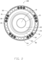
FIG. 2 is an isometric view of a second section of a single core submarine cable according to the invention. -
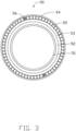
FIG. 3 is an isometric view of a first protecting layer of the single core submarine cable according to the invention. -
FIG. 4 is an isometric view of a fiber unit of the single core submarine cable according to the invention. - In the attached figures, single core submarine cable is labeled 100, cable core is labeled 10, inner protecting layer is labeled 20, armor layer is labeled 30, first metal wire is labeled 31, second metal wire is labeled 32, outer protecting layer is labeled 40, conductor shielding layer is labeled 21, insulation layer is labeled 22, insulation shielding layer is labeled 23, first protective layer is labeled 50, water-resistant tape winding layer is labeled 51, metal protective layer is labeled 52, polyethylene protective layer is labeled 53, lining layer is labeled 54, filling protective layer is labeled 55, fiber unit is labeled 56, fiber is labeled 56-a, water-resisting ointment is labeled 56-b, stainless steel tube is labeled 56-c, and plastic protective layer is labeled 56-d.
- It will be appreciated that for simplicity and clarity of illustration, where appropriate, reference numerals have been repeated among the different figures to indicate corresponding or analogous elements. In addition, numerous specific details are set forth in order to provide a thorough understanding of the embodiments described herein. However, it will be understood by those of ordinary skill in the art that the embodiments described herein can be practiced without these specific details. In other instances, methods, procedures, and components have not been described in detail so as not to obscure the related relevant feature being described. Also, the description is not to be considered as limiting the scope of the embodiments described herein. The drawings are not necessarily to scale and the proportions of certain parts may be exaggerated to better illustrate details and features of the present disclosure.
-
FIG. 1 illustrates a singlecore submarine cable 100. Thecable 100 includes acable core 10, an inner protectinglayer 20 positioned outside of thecable core 10, and anarmor layer 30 positioned outside of the inner protectinglayer 20. The singlecore submarine cable 100 is used for underwater power transmission, for example, supplying power to coastal cities and transmitting power generated by offshore wind power. Thearmor layer 30 includesfirst metal wires 31 andsecond wires 32 with a constant sum of number. The number of the first and second metal wires is different at least between a first section and a second section. -
FIGS. 1 and2 illustrate thecable core 10 being positioned at the center of the singlecore submarine cable 100. Thecable core 10 includes a water-resistant conductor and a water-resistant filling material positioned in gaps of the water-resistant conductor. The water-resistant conductor is the carrier of electrical current in the singlecore submarine cable 100. The water-resistant filling material is gap filler material. The water-resistant filling material protects the water-resistant conductor. The water-resistant conductor is in the form of round compacted strand or shaped line. The water-resistant filling material is water-resistant tape, water-resistant powder, water-resistant yarn, water-resistant glue, or a combination thereof. -
FIGS. 2 and3 illustrate that the inner protectinglayer 20 is positioned outside of thecable core 10. The inner protectinglayer 20 acts as shielding, as insulation, and as protection for thecable core 10. The inner protectinglayer 20 includes aconductor shielding layer 21, aninsulation layer 22, aninsulation shielding layer 23, and a firstprotective layer 50 arranged in that order from the inside to the outside. Theconductor shielding layer 21 is formed by wrapping a semi-conductive binding water-resistant tape and extruding an ultra-smooth semi-conductive shielding material. Theinsulation layer 22 is formed on theconductor shielding layer 21 by an even extrusion of the ultra-clean cross-linked polyethylene material. Theinsulation shielding layer 23 is formed on theinsulation layer 22 by directly extruding the ultra-smooth semi-conductive shielding material. The firstprotective layer 50 includes a water-resistanttape winding layer 51, a metalprotective layer 52, a polyethyleneprotective layer 53, and alining layer 54 arranged in that order from the inside to the outside. The water-resistanttape winding layer 51 is formed on theinsulation shielding layer 23 by overlapping in wrapping semi-conducting resistant tape. The metalprotective layer 52 is a continuous sealing structure, formed on the water-resistanttape winding layer 51 by directly extruding the lead alloy material. The polyethyleneprotective layer 53 is formed on the metalprotective layer 52 by directly extruding semi-conductive polyethylene or insulating polyethylene thermoplastic sheathing material. Thelining layer 54 is of high strength polypropylene fiber rope winding structure with a diameter of 2~4 mm. -
FIG. 3 and4 illustrate that the singlecore submarine cable 100 includes a fillingprotective layer 55 and afiber unit 56. The singlecore submarine cable 100 is an optoelectric composite cable. The fillingprotective layer 55 is positioned between the polyethyleneprotective layer 53 and thelining layer 54. Thefiber unit 56 is positioned in gaps of the fillingprotective layer 55. The fillingprotective layer 55 is a cylinder formed by the continuous extrusion of high strength thermoplastic material, for filling and protecting thefiber unit 56. Thefiber unit 56 carries optical signals in the singlecore marine cable 100. Thefiber unit 56 includes a fiber 56-a, a water-resisting ointment 56-b, a stainless steel tube 56-c, and a plastic protective layer 56-d. The singlecore marine cable 100 includes two groups offiber units 56. Eachfiber unit 56 group includes 36 fibers. - In an alternative embodiment, the single
core marine cable 100 includes one, three, or four groups of fiber units. Each group offiber units 56 includes 1~36 fibers. The singlecore marine cable 100 may not include thefiber unit 56 and thefilling protecting layer 55. -
FIGS. 1 and2 illustrate that thearmor layer 30 includesfirst metal wires 31 andsecond metal wires 32 with a constant sum of number. The armor layer improves the mechanical strength and resistance to erosion and corrosion of the singlecore marine cable 100. Thefirst metal wires 31 are round copper wires, aluminium wires or a combination thereof. Thesecond metal wires 32 are round steel wires. The introduction of thefirst metal wires 31 reduces the resistance of the armor and electrical loss through the armor of thearmor layer 30. The carrying capacity of the singlecore submarine cable 100 meets the requirements of rated current in specific routes. For example, the rated current required by the singlecore submarine cable 100 is 700A, the carrying capacity of the steel wire armored cable under certain routing conditions is 650A, and the carrying capacity of the copper wire armored cable under the same conditions is 850A. The singlecore submarine cable 100 combines two kinds of metal wires to improve the characteristics of the armor. By calculating the diameter and number of the metal wires, the ratio of number of thefirst metal wires 31 and thesecond metal wires 32 is 2:5. The carrying capacity of the singlecore submarine cable 100 including the first and second metal wires with ratio of 2:5 under the certain routing conditions is 710A, and this meets the requirements of rated current under those conditions. - The number of the
first metal wires 31 and thesecond metal wires 32 is different between at least a first section and a second section. By adjusting the ratio of the number of the metal wires in different sections, the singlecore submarine cable 100 meets the requirements of rated current in multiple sections, and optimizes the mechanical strength and cost. For different laying areas and routing conditions, if the cable is prepared with high requirements for routing conditions of a bottleneck section, the carrying capacity of other sections will exceed the preset index. If the cable is prepared with requirements for routing conditions of other sections, the carrying capacity will not meet the high requirements for routing conditions of the bottleneck section. A submarine cable set up to meet high requirements for routing conditions of the bottleneck section has general mechanical performance and high cost. For example, it is assumed that the first section is laid under the routing conditions of other sections, and the second section is laid under the routing conditions of a bottleneck section. The rated current required for the singlecore submarine cable 100 is 700A, the carrying capacity of the first section of the singlecore submarine cable 100 is 720A, and the carrying capacity of the first section of the singlecore submarine cable 100 laid under the routing conditions of the second section is 630A. The carrying capacity of the first section of the singlecore submarine cable 100 laid under the routing conditions of the second section does not meet the rated current required, thus the second section of the route will be a bottleneck section of the route. Referring to the constant sum of the number, the number of the first wires on the second section is increased to improve the carrying capacity of the second section by joining thefirst wire 31 with thesecond wire 32, the carrying capacity of the first section of the singlecore submarine cable 100 laid under the routing conditions of the second section thus meet the rated current required. The singlecore submarine cable 100 is able to meet the requirements of rated currents in the first and second sections simultaneously.FIGS. 1 and2 illustrate that thefirst metal wires 31 and thesecond metal wires 32 on the first and second sections are continuously arranged around the circumference of theinner protecting layer 20, cross sections of thefirst metal wires 31 and thesecond metal wires 32 are distributed a same circumference surface. The number of thefirst metal wires 31 and thesecond metal wires 32 is different between the first and second sections. The ratio of the number between the first section and the second section of thefirst wires 31 is 2:3, the ratio of the number between the first section and the second section of thesecond wires 32 is 5:4, the sum of the number of thefirst metal wires 31 and thesecond metal wires 32 always being constant. The carrying capacity of the first section can be 720A, and the carrying capacity of the second section can be 710A, both of which meet the preset rated current requirements of 700A. Anouter protecting layer 40 is positioned outside of thearmor layer 30, theouter protecting layer 40 provides mechanical protection and corrosion resistance to thearmor layer 30, theouter protecting layer 40 is formed by wrapping the polypropylene fibers with diameter of 2~4 mm and coating with pitch or the like. - In an alternative embodiment, not covered by claims, the
first metal wires 31 and thesecond metal wires 32 are flat wires. Thefirst metal wires 31 are of aluminum or a combination of aluminum and copper. The number of thefirst metal wires 31 and thesecond metal wires 32 has more than two groups of different values on different sections of the singlecore submarine cable 100. To meet the requirements of rated current, the number of thefirst metal wires 31 is reduced and the number of thesecond metal wires 32 is increased to optimize mechanical strength and reduce cost of the singlecore submarine cable 100. Thefirst metal wires 31 and thesecond metal wires 32 are arranged continuously but irregularly. The material of theouter protecting layer 40 can be polyethylene, polypropylene, polyvinylchloride, polyolefin, or a combination thereof. - The single core submarine cable of the present disclosure meets the requirements of rated current in multiple sections with different routing conditions, and optimizes the mechanical strength and cost.
- The embodiments shown and described above are only examples. Many details in this field are found in the relevant art. Therefore, many such details are neither shown nor described. Even though numerous characteristics and advantages of the present technology have been set forth in the foregoing description, together with details of the structure and function of the present disclosure, the disclosure is illustrative only, and changes may be made in the detail, especially in matters of shape, size, and arrangement of the parts within the principles of the present disclosure, up to and including the full extent established by the broad general meaning of the terms used in the claims. Therefore, those of ordinary skill in the art can make various modifications to the embodiments without departing from the scope of the disclosure, as defined by the appended claims.
Claims (8)
- A single core submarine cable (100) comprising:a cable core (10);an inner protecting layer (20) positioned outside of the cable core (10); andan armor layer (30) positioned outside of the inner protecting layer (20), wherein the single core submarine cable comprises a first section and a second section, characterized in that, the armor layer (30) comprises first metal wires (31) and second metal wires (32) with a constant sum of number in the first section and the second section of the single core submarine cable (100), the number of the first metal wires (31) and the second metal wires (32) is different between the first section and the second section, the first metal wires (31) and the second metal wires (32) on the first and second sections are continuously arranged around the circumference of the inner protecting layer (20), wherein the first metal wires (31) are copper wires, aluminium wires, or a combination thereof and the second wires (32) are steel wires.
- The single core submarine cable (100) of claim 1, wherein both of the first metal wires (31) and the second metal wires (32) are round wires or flat wires.
- The single core submarine cable (100) of claim 1, wherein the cable core (10) comprises a water-resistant conductor and a water-resistant filling material positioned in gaps of the water-resistant conductor.
- The single core submarine cable (100) of claim 1, wherein the inner protecting layer (20) is positioned outside of the cable core (10), and comprises a conductor shielding layer (21), an insulation layer (22), an insulation shielding layer (23), and a first protective layer (50) arranged in that order from the inside to the outside.
- The single core submarine cable (100) of claim 4, wherein the first protective layer (50) includes a water-resistant tape winding layer (51), a metal protective layer (52), a polyethylene protective layer (53), and a lining layer (54) arranged in that order from the inside to the outside.
- The single core submarine cable (100) of claim 5, wherein a filling protective layer (55) is positioned between the polyethylene protective layer (53) and the lining layer (54), and a fiber unit (56) is positioned in the gaps of the filling protective layer (55).
- The single core submarine cable (100) of claim 6, wherein the fiber unit (56) includes a fiber (56-a), a water-resisting ointment (56-b), a stainless steel tube (56-c), and a plastic protective layer (56-d).
- The single core submarine cable (100) of claim 1, wherein an outer protecting layer (40) is positioned outside of the armor layer (30).
Applications Claiming Priority (2)
| Application Number | Priority Date | Filing Date | Title |
|---|---|---|---|
| CN201710892817.8A CN109559846B (en) | 2017-09-27 | 2017-09-27 | Single-core submarine cable |
| PCT/CN2017/104048 WO2019061176A1 (en) | 2017-09-27 | 2017-09-28 | Single-core submarine cable |
Publications (4)
| Publication Number | Publication Date |
|---|---|
| EP3564970A1 EP3564970A1 (en) | 2019-11-06 |
| EP3564970A4 EP3564970A4 (en) | 2020-10-14 |
| EP3564970B1 true EP3564970B1 (en) | 2025-03-12 |
| EP3564970C0 EP3564970C0 (en) | 2025-03-12 |
Family
ID=65864272
Family Applications (1)
| Application Number | Title | Priority Date | Filing Date |
|---|---|---|---|
| EP17927143.2A Active EP3564970B1 (en) | 2017-09-27 | 2017-09-28 | Single-core submarine cable |
Country Status (5)
| Country | Link |
|---|---|
| EP (1) | EP3564970B1 (en) |
| CN (1) | CN109559846B (en) |
| ES (1) | ES3018289T3 (en) |
| PL (1) | PL3564970T3 (en) |
| WO (1) | WO2019061176A1 (en) |
Families Citing this family (4)
| Publication number | Priority date | Publication date | Assignee | Title |
|---|---|---|---|---|
| CN111326288B (en) * | 2020-04-01 | 2021-03-30 | 杭州智海人工智能有限公司 | Wind power generation high-voltage direct-current submarine cable |
| CN114645977A (en) * | 2020-12-17 | 2022-06-21 | 无棣海忠软管制造有限公司 | Marine non-bonded flexible pipeline with skin heat tracing function |
| CN113539563B (en) * | 2021-07-16 | 2022-06-03 | 广东汕沪电缆有限公司 | Enhanced polyvinyl chloride power cable and preparation method thereof |
| EP4489034A1 (en) * | 2023-07-05 | 2025-01-08 | Nexans | Method for manufacturing a composite electric power cable |
Family Cites Families (12)
| Publication number | Priority date | Publication date | Assignee | Title |
|---|---|---|---|---|
| CN201160014Y (en) * | 2007-12-13 | 2008-12-03 | 上海波汇通信科技有限公司 | High voltage power cable of composite optical fiber |
| CN101807450B (en) * | 2010-03-29 | 2012-10-31 | 浙江省电力公司舟山电力局 | Sea electric power cable |
| NO333569B1 (en) * | 2011-03-15 | 2013-07-08 | Nexans | The umbilical power cable |
| CN102969071B (en) * | 2012-12-13 | 2015-03-25 | 江苏远洋东泽电缆股份有限公司 | Submarine cable with increased current-carrying capacity |
| KR101991553B1 (en) * | 2015-09-30 | 2019-06-20 | 엘에스전선 주식회사 | Submarine cable having bimetallic armours |
| CN205789189U (en) * | 2016-07-19 | 2016-12-07 | 舟山启明电力设计院有限公司 | A kind of single sea electric power cable of segmentation armouring |
| CN205789190U (en) * | 2016-07-19 | 2016-12-07 | 舟山启明电力设计院有限公司 | A kind of clamp device for segmentation armouring sea cable |
| CN205911042U (en) * | 2016-08-08 | 2017-01-25 | 中天科技海缆有限公司 | Compound submarine cable that exchanges of big cross -section molded lines conductor 500kV optic fibre |
| CN106098238A (en) * | 2016-08-08 | 2016-11-09 | 中天科技海缆有限公司 | 500kV cross-linked polyethylene insulating submarine power cable |
| CN106128582A (en) * | 2016-08-08 | 2016-11-16 | 中天科技海缆有限公司 | A kind of heavy in section molded line conductor 500kV Optical Fiber Composite exchange submarine cable |
| CN106094145A (en) * | 2016-08-29 | 2016-11-09 | 中天科技海缆有限公司 | A kind of proportion adjustable type submarine optical fiber cable |
| CN207264809U (en) * | 2017-09-27 | 2018-04-20 | 中天科技海缆有限公司 | Single extra large cable |
-
2017
- 2017-09-27 CN CN201710892817.8A patent/CN109559846B/en active Active
- 2017-09-28 ES ES17927143T patent/ES3018289T3/en active Active
- 2017-09-28 PL PL17927143.2T patent/PL3564970T3/en unknown
- 2017-09-28 EP EP17927143.2A patent/EP3564970B1/en active Active
- 2017-09-28 WO PCT/CN2017/104048 patent/WO2019061176A1/en not_active Ceased
Also Published As
| Publication number | Publication date |
|---|---|
| WO2019061176A1 (en) | 2019-04-04 |
| EP3564970A1 (en) | 2019-11-06 |
| EP3564970A4 (en) | 2020-10-14 |
| CN109559846A (en) | 2019-04-02 |
| EP3564970C0 (en) | 2025-03-12 |
| PL3564970T3 (en) | 2025-05-26 |
| CN109559846B (en) | 2024-04-19 |
| ES3018289T3 (en) | 2025-05-14 |
Similar Documents
| Publication | Publication Date | Title |
|---|---|---|
| US7272281B2 (en) | Powered fiber cable | |
| US7629535B2 (en) | Electric submarine power cable and system for direct electric heating | |
| CN210006533U (en) | direct current submarine cable for deep sea | |
| EP3564970A1 (en) | Single-core submarine cable | |
| CN101807450A (en) | Sea electric power cable | |
| CN108109742A (en) | Submarine optical fiber cable and preparation method thereof | |
| CN201725627U (en) | Undersea power cable | |
| CN101887781B (en) | Self-supporting lightning-proof optical cable | |
| CN209766059U (en) | Umbilical cable with armor layer for hose composite strong-current underwater production system | |
| KR20200062655A (en) | Photovoltaic composite low toxicity flame retardant wire and its structure | |
| CN112397227A (en) | Submarine optoelectronic composite cable | |
| CN209912547U (en) | Armored high-strength composite umbilical cable for underwater production system of strong electricity | |
| EP2360503B1 (en) | Method of stripping an outer layer from an intermediate layer of a cable, cable, distribution system, and base station thereof | |
| CN203260336U (en) | Self-supporting overhead anti-bird pecking photoelectric hybrid cable | |
| CN102222541A (en) | Anti-corrosion submarine cable with low armoring loss for communication monitoring | |
| CN205656899U (en) | Compound environmental protection cable of multipurpose | |
| CN207264809U (en) | Single extra large cable | |
| CN105529102A (en) | Optical-power composite cable with metal sheath employing soft aluminum alloy profile conductors | |
| CN101887782B (en) | Lightning-protection optical cable | |
| CN101887780B (en) | Multigroup lightning protection optical cable | |
| CN209880223U (en) | Self-bearing power cable | |
| CN210015734U (en) | Photoelectric hybrid cable | |
| CN220933801U (en) | Composite photoelectric control cable | |
| CN213242051U (en) | Direct-current high-voltage cable | |
| SE2051130A1 (en) | Torsion-balanced electrical power cables |
Legal Events
| Date | Code | Title | Description |
|---|---|---|---|
| STAA | Information on the status of an ep patent application or granted ep patent |
Free format text: STATUS: THE INTERNATIONAL PUBLICATION HAS BEEN MADE |
|
| PUAI | Public reference made under article 153(3) epc to a published international application that has entered the european phase |
Free format text: ORIGINAL CODE: 0009012 |
|
| STAA | Information on the status of an ep patent application or granted ep patent |
Free format text: STATUS: REQUEST FOR EXAMINATION WAS MADE |
|
| 17P | Request for examination filed |
Effective date: 20190731 |
|
| AK | Designated contracting states |
Kind code of ref document: A1 Designated state(s): AL AT BE BG CH CY CZ DE DK EE ES FI FR GB GR HR HU IE IS IT LI LT LU LV MC MK MT NL NO PL PT RO RS SE SI SK SM TR |
|
| AX | Request for extension of the european patent |
Extension state: BA ME |
|
| RAP1 | Party data changed (applicant data changed or rights of an application transferred) |
Owner name: ZHONGTIAN TECHNOLOGY SUBMARINE CABLES CO., LTD. |
|
| A4 | Supplementary search report drawn up and despatched |
Effective date: 20200915 |
|
| RIC1 | Information provided on ipc code assigned before grant |
Ipc: H01B 7/14 20060101AFI20200909BHEP Ipc: H01B 7/22 20060101ALI20200909BHEP |
|
| DAV | Request for validation of the european patent (deleted) | ||
| DAX | Request for extension of the european patent (deleted) | ||
| STAA | Information on the status of an ep patent application or granted ep patent |
Free format text: STATUS: EXAMINATION IS IN PROGRESS |
|
| 17Q | First examination report despatched |
Effective date: 20210406 |
|
| GRAP | Despatch of communication of intention to grant a patent |
Free format text: ORIGINAL CODE: EPIDOSNIGR1 |
|
| STAA | Information on the status of an ep patent application or granted ep patent |
Free format text: STATUS: GRANT OF PATENT IS INTENDED |
|
| INTG | Intention to grant announced |
Effective date: 20241220 |
|
| GRAS | Grant fee paid |
Free format text: ORIGINAL CODE: EPIDOSNIGR3 |
|
| GRAA | (expected) grant |
Free format text: ORIGINAL CODE: 0009210 |
|
| STAA | Information on the status of an ep patent application or granted ep patent |
Free format text: STATUS: THE PATENT HAS BEEN GRANTED |
|
| AK | Designated contracting states |
Kind code of ref document: B1 Designated state(s): AL AT BE BG CH CY CZ DE DK EE ES FI FR GB GR HR HU IE IS IT LI LT LU LV MC MK MT NL NO PL PT RO RS SE SI SK SM TR |
|
| REG | Reference to a national code |
Ref country code: GB Ref legal event code: FG4D |
|
| REG | Reference to a national code |
Ref country code: CH Ref legal event code: EP |
|
| REG | Reference to a national code |
Ref country code: DE Ref legal event code: R096 Ref document number: 602017088355 Country of ref document: DE |
|
| REG | Reference to a national code |
Ref country code: IE Ref legal event code: FG4D |
|
| U01 | Request for unitary effect filed |
Effective date: 20250325 |
|
| U07 | Unitary effect registered |
Designated state(s): AT BE BG DE DK EE FI FR IT LT LU LV MT NL PT RO SE SI Effective date: 20250331 |
|
| REG | Reference to a national code |
Ref country code: GR Ref legal event code: EP Ref document number: 20250400787 Country of ref document: GR Effective date: 20250514 |
|
| PG25 | Lapsed in a contracting state [announced via postgrant information from national office to epo] |
Ref country code: RS Free format text: LAPSE BECAUSE OF FAILURE TO SUBMIT A TRANSLATION OF THE DESCRIPTION OR TO PAY THE FEE WITHIN THE PRESCRIBED TIME-LIMIT Effective date: 20250612 |
|
| PG25 | Lapsed in a contracting state [announced via postgrant information from national office to epo] |
Ref country code: HR Free format text: LAPSE BECAUSE OF FAILURE TO SUBMIT A TRANSLATION OF THE DESCRIPTION OR TO PAY THE FEE WITHIN THE PRESCRIBED TIME-LIMIT Effective date: 20250312 |
|
| U20 | Renewal fee for the european patent with unitary effect paid |
Year of fee payment: 9 Effective date: 20250826 |
|
| PG25 | Lapsed in a contracting state [announced via postgrant information from national office to epo] |
Ref country code: SM Free format text: LAPSE BECAUSE OF FAILURE TO SUBMIT A TRANSLATION OF THE DESCRIPTION OR TO PAY THE FEE WITHIN THE PRESCRIBED TIME-LIMIT Effective date: 20250312 |
|
| PGFP | Annual fee paid to national office [announced via postgrant information from national office to epo] |
Ref country code: GR Payment date: 20250919 Year of fee payment: 9 |
|
| PGFP | Annual fee paid to national office [announced via postgrant information from national office to epo] |
Ref country code: PL Payment date: 20250919 Year of fee payment: 9 |
|
| PG25 | Lapsed in a contracting state [announced via postgrant information from national office to epo] |
Ref country code: CZ Free format text: LAPSE BECAUSE OF FAILURE TO SUBMIT A TRANSLATION OF THE DESCRIPTION OR TO PAY THE FEE WITHIN THE PRESCRIBED TIME-LIMIT Effective date: 20250312 |
|
| PGFP | Annual fee paid to national office [announced via postgrant information from national office to epo] |
Ref country code: IE Payment date: 20250918 Year of fee payment: 9 |
|
| PG25 | Lapsed in a contracting state [announced via postgrant information from national office to epo] |
Ref country code: SK Free format text: LAPSE BECAUSE OF FAILURE TO SUBMIT A TRANSLATION OF THE DESCRIPTION OR TO PAY THE FEE WITHIN THE PRESCRIBED TIME-LIMIT Effective date: 20250312 |
|
| PGFP | Annual fee paid to national office [announced via postgrant information from national office to epo] |
Ref country code: IS Payment date: 20250930 Year of fee payment: 9 |
|
| PGFP | Annual fee paid to national office [announced via postgrant information from national office to epo] |
Ref country code: GB Payment date: 20251023 Year of fee payment: 9 |
|
| PGFP | Annual fee paid to national office [announced via postgrant information from national office to epo] |
Ref country code: NO Payment date: 20250930 Year of fee payment: 9 |
|
| PLBE | No opposition filed within time limit |
Free format text: ORIGINAL CODE: 0009261 |
|
| STAA | Information on the status of an ep patent application or granted ep patent |
Free format text: STATUS: NO OPPOSITION FILED WITHIN TIME LIMIT |
|
| REG | Reference to a national code |
Ref country code: CH Ref legal event code: L10 Free format text: ST27 STATUS EVENT CODE: U-0-0-L10-L00 (AS PROVIDED BY THE NATIONAL OFFICE) Effective date: 20260121 |
|
| PGFP | Annual fee paid to national office [announced via postgrant information from national office to epo] |
Ref country code: ES Payment date: 20251017 Year of fee payment: 9 |
|
| 26N | No opposition filed |
Effective date: 20251215 |
|
| REG | Reference to a national code |
Ref country code: CH Ref legal event code: H13 Free format text: ST27 STATUS EVENT CODE: U-0-0-H10-H13 (AS PROVIDED BY THE NATIONAL OFFICE) Effective date: 20260425 |