EP3564918A1 - In einen pneumatischen detektor integrierter alarm und fehlerschalter - Google Patents
In einen pneumatischen detektor integrierter alarm und fehlerschalter Download PDFInfo
- Publication number
- EP3564918A1 EP3564918A1 EP19171857.6A EP19171857A EP3564918A1 EP 3564918 A1 EP3564918 A1 EP 3564918A1 EP 19171857 A EP19171857 A EP 19171857A EP 3564918 A1 EP3564918 A1 EP 3564918A1
- Authority
- EP
- European Patent Office
- Prior art keywords
- diaphragm
- integrated switch
- retainer portion
- fault
- alarm
- Prior art date
- Legal status (The legal status is an assumption and is not a legal conclusion. Google has not performed a legal analysis and makes no representation as to the accuracy of the status listed.)
- Withdrawn
Links
Images


Classifications
-
- H—ELECTRICITY
- H01—ELECTRIC ELEMENTS
- H01H—ELECTRIC SWITCHES; RELAYS; SELECTORS; EMERGENCY PROTECTIVE DEVICES
- H01H35/00—Switches operated by change of a physical condition
- H01H35/24—Switches operated by change of fluid pressure, by fluid pressure waves, or by change of fluid flow
- H01H35/26—Details
- H01H35/2671—Means to detect leaks in the pressure sensitive element
-
- G—PHYSICS
- G08—SIGNALLING
- G08B—SIGNALLING SYSTEMS, e.g. PERSONAL CALLING SYSTEMS; ORDER TELEGRAPHS; ALARM SYSTEMS
- G08B13/00—Burglar, theft or intruder alarms
- G08B13/20—Actuation by change of fluid pressure
-
- G—PHYSICS
- G08—SIGNALLING
- G08B—SIGNALLING SYSTEMS, e.g. PERSONAL CALLING SYSTEMS; ORDER TELEGRAPHS; ALARM SYSTEMS
- G08B17/00—Fire alarms; Alarms responsive to explosion
- G08B17/04—Hydraulic or pneumatic actuation of the alarm, e.g. by change of fluid pressure
-
- G—PHYSICS
- G08—SIGNALLING
- G08B—SIGNALLING SYSTEMS, e.g. PERSONAL CALLING SYSTEMS; ORDER TELEGRAPHS; ALARM SYSTEMS
- G08B21/00—Alarms responsive to a single specified undesired or abnormal condition and not otherwise provided for
- G08B21/18—Status alarms
- G08B21/182—Level alarms, e.g. alarms responsive to variables exceeding a threshold
-
- H—ELECTRICITY
- H01—ELECTRIC ELEMENTS
- H01H—ELECTRIC SWITCHES; RELAYS; SELECTORS; EMERGENCY PROTECTIVE DEVICES
- H01H35/00—Switches operated by change of a physical condition
- H01H35/24—Switches operated by change of fluid pressure, by fluid pressure waves, or by change of fluid flow
- H01H35/34—Switches operated by change of fluid pressure, by fluid pressure waves, or by change of fluid flow actuated by diaphragm
Definitions
- the present invention relates to a pneumatic detector, and in particular, to a pneumatic detector with an integrated alarm and fault switch.
- a pneumatic detector is typically comprised of both an alarm switch and a fault switch.
- Pneumatic detectors typically utilize a pressure tube that contains a gas that will expand as it is heated, thus increasing the pressure in the tube.
- An alarm switch is used to indicate overheat or fire situations.
- An alarm switch will include a deformable diaphragm that is at a normal state when the system is at a normal pressure. As the pressure rises, the diaphragm will deform and close an electrical circuit, indicating that there is an alarm condition in the system.
- a fault switch is used to indicate whether there are leaks, disconnects, or other problems in a pneumatic detector system.
- a fault switch will include a deformable diaphragm that is deformed when the system is at a normal pressure. If the pressure drops below normal, the diaphragm will resume its normal state and open an electrical circuit, indicating that there is a fault condition in the system.
- Pneumatic detectors that utilize both alarm switches and fault switches are used on aircrafts to detect alarm and fault conditions.
- the pressure tubes for the alarm and fault switches can typically run anywhere from one foot long to fifty feet long, and can be placed in systems that are prone to overheating or fires.
- an integrated switch to indicate pressure changes in an environment includes a housing with a cavity between a first retainer portion and a second retainer portion, a first diaphragm held in the cavity of the housing to indicate fault conditions, and a second diaphragm held in the cavity of the housing to indicate alarm conditions.
- the first diaphragm is thinner than the second diaphragm.
- the first diaphragm and the second diaphragm are constructed out of metallic materials.
- normal pressure conditions exist at normal operating temperatures.
- normal operating temperatures are temperatures between a pre-set fault temperature and a pre-set alarm temperature.
- the first diaphragm deforms and the second diaphragm is in a normal undeformed configuration.
- the first diaphragm when there are normal pressure conditions, deforms and comes into contact with the second diaphragm.
- the first diaphragm and the second diaphragms when there are below normal pressure conditions, do not contact one another.
- the first diaphragm and the second diaphragm when there are below normal pressure conditions, are both in a normal undeformed configuration.
- the integrated switch of any of the above embodiments is for use in an advanced pneumatic detector system, the integrated switch further comprising a contact pin held in the first retainer portion, and a pressure tube connected to the cavity and running through the second retainer portion, wherein the first diaphragm is held in the cavity near the second retainer portion and the second diaphragm is held in the cavity near the first retainer portion.
- the pressure tube contains a gas that expands as it is heated.
- said integrated switch is in an electrical circuit for indicating pressure changes in an environment and further comprises an insulating material between the first retainer portion and the second retainer portion, wherein said contact pin is held in the first retainer portion with an insulating material between the contact pin and the first retainer portion, and a power source connected to the first diaphragm.
- contact between the first and second diaphragms sends a signal from the power source through the first diaphragm and to the second diaphragm.
- non-contact between the first and second diaphragms prevents the power source from sending a signal to the second diaphragm.
- contact between the second diaphragm and the contact pin sends a signal from the power source through the first diaphragm and the second diaphragm to the contact pin.
- the present invention relates to pneumatic detectors with integrated alarm and fault switches.
- An integrated alarm and fault switch will have one housing that contains two diaphragms. A first diaphragm will indicate fault conditions and a second diaphragm will indicate alarm conditions. Fault conditions typically occur when there is a disconnection, leak, or other problem in a system. Alarm conditions typically occur when there is overheat or a fire in a system.
- FIG. 1 is a side cross-sectional view of integrated switch 10, including both an alarm switch and a fault switch, when there is atmospheric pressure in integrated switch 10.
- Integrated switch 10 includes housing 11 (including first retainer portion 12 and second retainer portion 14), pressure tube 16, contact pin 18, fault diaphragm 20, alarm diaphragm 22, insulator 24, insulator 26, and cavity 28. In the embodiment seen, there is no pressure in integrated switch 10.
- Integrated switch 10 includes housing 11 that is constructed of first retainer portion 12 and second retainer portion 14. First retainer portion 12 and second retainer portion 14 are connected to one another with insulator 24 running between them. Housing 11 includes cavity 28 that is bound by first retainer portion 12 and second retainer portion 14. First retainer portion 12 contains contact pin 18 with insulator 26 running between first retainer portion 12 and contact pin 18. Second retainer portion 14 contains pressure tube 16. Pressure tube 16 extends into cavity 28. Fault diaphragm 20 and alarm diaphragm 22 are held between first retainer portion 12 and second retainer portion 14 in cavity 28. Fault diaphragm 20 is held in integrated switch 10 between insulator 24 and second retainer portion 14. Alarm diaphragm 22 is held in integrated switch 10 between first retainer portion 12 and insulator 24.
- First retainer portion 12 and second retainer portion 14 are constructed out of a refractory metallic material that is capable of conducting an electrical signal. Refractory materials are used so that the components can maintain their strength when they are subject to high temperatures.
- Fault diaphragm 20 and alarm diaphragm 22 are also constructed out of refractory metallic materials that are capable of conducting an electronic signal.
- Fault diaphragm 20 and alarm diaphragm 22 can have any thickness that allows fault diaphragm 20 and alarm diaphragm 22 to deform.
- Fault diaphragm 20 has a smaller thickness in the embodiment shown so that it deforms at lower pressures than alarm diaphragm 22. This allows integrated switch 10 to be used to indicate different pressure levels in integrated switch 10.
- Insulator 24 runs between first retainer portion 12 and second retainer portion 14 to insulate the two portions and to prevent electronic signals from being passed between them.
- Insulator 26 runs between first retainer portion 12 and contact pin 18 to insulate them and to prevent electronic signals from being passed between them.
- Insulator 24 and insulator 26 can be made of any material that is capable of acting as an electrical insulator.
- Pressure tube 16 runs through second retainer portion 14 and connects to cavity 28.
- Pressure tube 16 contains a gas that expands as it is heated, therefore as pressure tube 16 is heated the pressure in pressure tube 16 will increase. As the pressure in pressure tube 16 increases, the pressure in cavity 28 will also increase. The pressure in cavity 28 can cause fault diaphragm 20 and alarm diaphragm 22 to deform. In the embodiment shown in FIG. 1 , there is no pressure in integrated switch 10 and fault diaphragm 20 and alarm diaphragm 22 are in their normal configuration.
- Pressure tube 16 can have a typical length between 0.305 meters (1 foot) and 15.24 meters (50 feet) depending on where integrated switch 10 will be used. Pressure tube 16 will be placed next to components that are capable of overheating or components where a fire could occur, such as an engine or auxiliary power unit.
- Contact pin 18 is held in first retainer portion 12 with insulator 26 running between contact pin 18 and first retainer portion 12. If the pressure in integrated switch 10 gets high enough, fault diaphragm 20 and alarm diaphragm 22 can both deform and come into contact with contact pin 18. A signal can then be sent through contact pin 18. Insulator 26 acts as a barrier and only allows the signal to travel through contact pin 18 and not through first retainer portion 12.
- Integrated switch 10 is advantageous over the prior art models, as it is reduced in size and weight.
- Integrated switch 10 can be used in pneumatic detector systems, making these systems smaller, lighter, and more compact.
- the reduction in size means integrated switch 10 can be used more efficiently in pneumatic detector systems.
- a reduction in size and weight also makes integrated switch 10 advantageous for use in applications where space is limited and weight needs to be kept to a minimum. If integrated switch 10 is housed in a housing, having a smaller and lighter system is also advantageous, as the size of the housing needed can be reduced.
- Integrated switch 10 also requires less parts than prior art models, which reduces the cost of the system and simplifies the manufacturing process. A lower cost and simpler manufacturing process are advantageous over the prior art systems. An integrated switch is also advantageous over prior art systems that utilized separate fault switches and alarm switches, as it reduces the possibility of having a disconnection, leak, or other problem in the system.
- FIG. 2 is a side cross-sectional view of integrated switch 10 in system 40 at a normal pressure.
- Integrated switch 10 includes housing 11 (including first retainer portion 12 and second retainer portion 14), pressure tube 16, contact pin 18, fault diaphragm 20, alarm diaphragm 22, insulator 24, insulator 26, and cavity 28.
- System 40 includes power source 42 and electronic controller 44. Integrated switch 10 and system 40 are connected to one another with path A, path B, path C, and path D.
- Integrated switch 10 is included in system 40 in the embodiment shown.
- System 40 includes power source 42 that is connected to fault diaphragm 20 along path A.
- Power source 42 can include any power source that is capable of supplying electric power to integrated switch 10.
- System 40 also includes electronic controller 44.
- Electronic controller 44 is connected to integrated switch 10 to read the signals being sent from integrated switch 10.
- Electronic controller 44 is connected to alarm diaphragm 22 along path B and to contact pin 18 along path C.
- System 40 also includes path D exiting electronic controller 44 to send a signal to an electronic component that will indicate what type of pressure conditions are present in integrated switch 10. These electronic components can include electrical equipment in the cockpit of an aircraft.
- FIG. 2 depicts integrated switch 10 at normal pressure conditions.
- normal pressure conditions exist under normal operating temperatures.
- Normal operating temperatures exist between a pre-set fault temperature and a pre-set alarm temperature.
- the pre-set fault temperature defines a lower limit of the normal operating temperatures and is the point at which pressure conditions will drop below normal.
- Fault diaphragm 20 will deform when the temperature rises above the pre-set fault temperature.
- the pre-set alarm temperature defines an upper limit of the normal operating temperatures and is the point at which pressure conditions will rise above normal.
- Alarm diaphragm 22 will deform when the temperature rises above the pre-set alarm temperature. Normal pressure conditions thus exist between the pre-set fault temperature and the pre-set alarm temperature. At normal pressure conditions, fault diaphragm 20 deforms and comes into contact with alarm diaphragm 22.
- integrated switch 10 in pneumatic detectors is advantageous, as integrated switch 10 can send a signal that indicates a system is at a steady state. This allows a user to verify that the pneumatic detector is operable and that the system is functioning normally.
- FIG. 3 is a side cross-sectional view of the integrated switch of FIG. 2 at a higher than normal pressure.
- Integrated switch 10 includes housing 11 (including first retainer portion 12 and second retainer portion 14), pressure tube 16, contact pin 18, fault diaphragm 20, alarm diaphragm 22, insulator 24, insulator 26, and cavity 28.
- System 40 includes power source 42 and electronic controller 44. Integrated switch 10 and system 40 are connected to one another with path A, path B, path C, and path D.
- FIG. 3 depicts integrated switch 10 at above normal pressure conditions. Above normal pressure conditions exist at temperatures above the pre-set alarm temperature. In the embodiment shown, the pre-set alarm temperature of the sensor is 316 degrees Celsius (600.00 degrees Fahrenheit). Temperatures above the pre-set alarm temperature of the sensor will cause above normal pressure conditions. In alternate embodiments, the pre-set alarm temperature of the sensor can vary based on the thickness of alarm diaphragm 22 in integrated switch 10 and the quantity of gas contained in pressure tube 16. At above normal pressure conditions, both fault diaphragm 20 and alarm diaphragm 22 will deform. This will cause fault diaphragm 20 to come into contact with alarm diaphragm 22 and it will cause alarm diaphragm 22 to come into contact with contact pin 18.
- an electronic signal is being sent through fault diaphragm 20 from power source 42.
- fault diaphragm 20 comes into contact with alarm diaphragm 22 under normal pressure conditions
- an electrical circuit between the two is closed and the electric signal from power source 42 will travel through fault diaphragm 20 to alarm diaphragm 22.
- alarm diaphragm 22 comes into contact with contact pin 18, an electrical circuit between them is closed and the electric signal will travel through alarm diaphragm 22 to contact pin 18.
- This electric signal can then travel through contact pin 18 and along path C to electronic controller 44.
- Electronic controller 44 will register this electric signal and will send out a signal along path D indicating that there are above normal pressure conditions in integrated switch 10.
- Pressure tube 16 can run along these components. As the heat rises in or around the components, the pressure in pressure tube 16 will increase, which will increase the pressure in cavity 28 of integrated switch 10. If the temperatures get above the pre-set alarm temperature, the pressure will get high enough to cause alarm diaphragm 22 to deform and come into contact with contact pin 18. This closes the circuit between alarm diaphragm 22 and contact pin 18 and causes an electric signal to travel between the two. This signal will be sent to electronic controller 44. Electronic controller 44 can then send a signal indicating that there is an alarm condition in integrated switch 10.
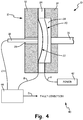
- FIG. 4 is a side cross-sectional view of the integrated switch of FIG. 2 at a lower than normal pressure.
- Integrated switch 10 includes housing 11 (including first retainer portion 12 and second retainer portion 14), pressure tube 16, contact pin 18, fault diaphragm 20, alarm diaphragm 22, insulator 24, insulator 26, and cavity 28.
- System 40 includes power source 42 and electronic controller 44. Integrated switch 10 and system 40 are connected to one another with path A, path B, path C, and path D.
- FIG. 4 depicts integrated switch 10 at below normal pressure conditions. Below normal pressure conditions exist at temperatures below the pre-set fault temperature of the sensor.
- the pre-set fault temperature of the sensor is -54 degrees Celsius (-65 degrees Fahrenheit), which is the temperature at a lower limit of the normal operating temperatures. Temperatures below the pre-set fault temperature of the sensor will cause below normal pressure conditions.
- the pre-set fault temperature of the sensor can vary based on the thickness of fault diaphragm 20 in integrated switch 10. At below normal pressure conditions, both fault diaphragm 20 and alarm diaphragm 22 will be in their normal configuration and they will not be touching.
- an electronic signal is being sent through fault diaphragm 20 from power source 42. Because fault diaphragm 20 is not in contact with alarm diaphragm 22 when there are below normal pressure conditions, an electrical circuit between the two is open. The electric signal from power source 42 will not travel through fault diaphragm 20 and alarm diaphragm 22 to electronic controller 44. Electronic controller 44 will register that there is no electric signal coming in and will send out a signal along path D indicating that there are below normal pressure conditions in integrated switch 10.
Landscapes
- Physics & Mathematics (AREA)
- Fluid Mechanics (AREA)
- General Physics & Mathematics (AREA)
- Business, Economics & Management (AREA)
- Emergency Management (AREA)
- Measuring Fluid Pressure (AREA)
- Fire-Detection Mechanisms (AREA)
- Switches Operated By Changes In Physical Conditions (AREA)
Applications Claiming Priority (2)
| Application Number | Priority Date | Filing Date | Title |
|---|---|---|---|
| US13/836,675 US9153400B2 (en) | 2013-03-15 | 2013-03-15 | Pneumatic detector integrated alarm and fault switch |
| EP14159615.5A EP2779125B1 (de) | 2013-03-15 | 2014-03-13 | In einen pneumatischen Detektor integrierter Alarm und Schalter |
Related Parent Applications (1)
| Application Number | Title | Priority Date | Filing Date |
|---|---|---|---|
| EP14159615.5A Division EP2779125B1 (de) | 2013-03-15 | 2014-03-13 | In einen pneumatischen Detektor integrierter Alarm und Schalter |
Publications (1)
| Publication Number | Publication Date |
|---|---|
| EP3564918A1 true EP3564918A1 (de) | 2019-11-06 |
Family
ID=50289438
Family Applications (2)
| Application Number | Title | Priority Date | Filing Date |
|---|---|---|---|
| EP19171857.6A Withdrawn EP3564918A1 (de) | 2013-03-15 | 2014-03-13 | In einen pneumatischen detektor integrierter alarm und fehlerschalter |
| EP14159615.5A Active EP2779125B1 (de) | 2013-03-15 | 2014-03-13 | In einen pneumatischen Detektor integrierter Alarm und Schalter |
Family Applications After (1)
| Application Number | Title | Priority Date | Filing Date |
|---|---|---|---|
| EP14159615.5A Active EP2779125B1 (de) | 2013-03-15 | 2014-03-13 | In einen pneumatischen Detektor integrierter Alarm und Schalter |
Country Status (6)
| Country | Link |
|---|---|
| US (1) | US9153400B2 (de) |
| EP (2) | EP3564918A1 (de) |
| CN (1) | CN104051186B (de) |
| BR (1) | BR102014006081B1 (de) |
| CA (1) | CA2843977C (de) |
| ES (1) | ES2729330T3 (de) |
Families Citing this family (14)
| Publication number | Priority date | Publication date | Assignee | Title |
|---|---|---|---|---|
| US9649520B2 (en) * | 2014-07-11 | 2017-05-16 | Kidde Technologies, Inc. | Burst disc puncture pressure-imbalance actuator for a fire extinguisher |
| US9821183B2 (en) | 2014-07-11 | 2017-11-21 | Kidde Technologies, Inc. | Motorized actuator for a fire extinguisher |
| US9539452B2 (en) * | 2014-07-11 | 2017-01-10 | Kidde Technologies, Inc. | Rapid pressure diffusion actuator for a fire extinguisher |
| US9342969B2 (en) * | 2014-10-16 | 2016-05-17 | Kidde Technologies, Inc. | Pneumatic detector assembly with bellows |
| US9396636B2 (en) * | 2014-11-10 | 2016-07-19 | Kidde Technologies, Inc. | Pneumatic pressure detector for a fire alarm system and method of insulating |
| US9970837B2 (en) * | 2015-06-30 | 2018-05-15 | Kidde Technologies Inc. | Detector utilizing an adjustment screw and a bellows |
| JP6584962B2 (ja) * | 2016-01-06 | 2019-10-02 | 日本電産トーソク株式会社 | 油圧スイッチ |
| US10002508B2 (en) * | 2016-02-10 | 2018-06-19 | Kidde Technologies, Inc. | Pneumatic fire detectors |
| US10126196B2 (en) | 2016-07-29 | 2018-11-13 | Kidde Technologies, Inc. | Multi-condition sensor systems |
| US9922527B2 (en) * | 2016-07-29 | 2018-03-20 | Kidde Technologies, Inc. | Multi-condition sensor systems |
| US10466124B2 (en) * | 2016-12-19 | 2019-11-05 | Kidde Technologies, Inc. | In-situ functionality test feature for advance pneumatic detector |
| CN107234007B (zh) * | 2017-06-23 | 2022-11-01 | 湖南中工矿业工程技术有限公司 | 一种自动故障检测微泡枪及检测和控制方法 |
| CN109281729B (zh) * | 2018-09-25 | 2020-03-20 | 贵州吉利发动机有限公司 | 一种防通风管路结冰堵塞的装置和汽车发动机 |
| CN111453297A (zh) * | 2020-05-26 | 2020-07-28 | 攀钢集团矿业有限公司 | 一种损伤自报警皮带 |
Citations (2)
| Publication number | Priority date | Publication date | Assignee | Title |
|---|---|---|---|---|
| EP0503971A1 (de) * | 1991-03-15 | 1992-09-16 | Whittaker Corporation | Pneumatischer Druckdetektor |
| WO2009032973A2 (en) * | 2007-09-07 | 2009-03-12 | Pacific Scientific Company | Pneumatic fire detector |
Family Cites Families (9)
| Publication number | Priority date | Publication date | Assignee | Title |
|---|---|---|---|---|
| US1986479A (en) * | 1929-12-27 | 1935-01-01 | Automatic Sprinkler Co | Means for supervising pneumatic fire alarm systems |
| US2777028A (en) * | 1947-10-17 | 1957-01-08 | James M Kendall | Hydrostatic pressure switch |
| US3122728A (en) | 1959-05-25 | 1964-02-25 | Jr John E Lindberg | Heat detection |
| US3267233A (en) * | 1964-01-31 | 1966-08-16 | Sperry Rand Corp | Pneumatic transducer |
| GB1200193A (en) * | 1967-09-14 | 1970-07-29 | Dewandre Co Ltd C | Improvements in or relating to vehicle braking apparatus |
| US3710813A (en) | 1971-02-16 | 1973-01-16 | Hodgman Mfg Co Inc | Pneumatic fire detection system for deluge valve |
| US5621389A (en) | 1995-06-05 | 1997-04-15 | Whittaker Corp. | Apparatus for detecting a fire having a liquid filled sensor tube and compensation for changes in ambient temperature |
| US5691702A (en) | 1995-09-08 | 1997-11-25 | Whittaker Corporation | Pneumatic pressure detector for fire and ground fault detection |
| US6121883A (en) | 1999-12-22 | 2000-09-19 | Hatsir; Eli | Method and device for fluid pressure analytical electronic heat and fire detection |
-
2013
- 2013-03-15 US US13/836,675 patent/US9153400B2/en active Active
-
2014
- 2014-02-24 CA CA2843977A patent/CA2843977C/en active Active
- 2014-03-13 EP EP19171857.6A patent/EP3564918A1/de not_active Withdrawn
- 2014-03-13 EP EP14159615.5A patent/EP2779125B1/de active Active
- 2014-03-13 ES ES14159615T patent/ES2729330T3/es active Active
- 2014-03-14 CN CN201410094339.2A patent/CN104051186B/zh active Active
- 2014-03-14 BR BR102014006081-2A patent/BR102014006081B1/pt active IP Right Grant
Patent Citations (2)
| Publication number | Priority date | Publication date | Assignee | Title |
|---|---|---|---|---|
| EP0503971A1 (de) * | 1991-03-15 | 1992-09-16 | Whittaker Corporation | Pneumatischer Druckdetektor |
| WO2009032973A2 (en) * | 2007-09-07 | 2009-03-12 | Pacific Scientific Company | Pneumatic fire detector |
Also Published As
| Publication number | Publication date |
|---|---|
| ES2729330T3 (es) | 2019-10-31 |
| CN104051186A (zh) | 2014-09-17 |
| US20140262723A1 (en) | 2014-09-18 |
| EP2779125A2 (de) | 2014-09-17 |
| BR102014006081A2 (pt) | 2015-05-05 |
| BR102014006081B1 (pt) | 2022-06-21 |
| EP2779125A3 (de) | 2014-11-05 |
| US9153400B2 (en) | 2015-10-06 |
| CA2843977C (en) | 2021-01-05 |
| CN104051186B (zh) | 2018-03-30 |
| CA2843977A1 (en) | 2014-09-15 |
| EP2779125B1 (de) | 2019-05-01 |
Similar Documents
| Publication | Publication Date | Title |
|---|---|---|
| CA2843977C (en) | Pneumatic detector integrated alarm and fault switch | |
| US9523731B2 (en) | Diagnosis system for monitoring state of switchboard | |
| JP6605896B2 (ja) | 空気圧検出器組立体および空気圧検出器組立体を組み立てる方法 | |
| US8708554B2 (en) | Leak detection apparatus for aircraft bleed air systems | |
| JP6488132B2 (ja) | 一体型電気接点を有する空気圧式検出器 | |
| EP3336812B1 (de) | In-situ funktionalitätstest für pneumatischen vorschubdetektor | |
| US20160187174A1 (en) | Dual sensor head configuration in a fluid flow or liquid level switch | |
| EP3018642B1 (de) | Pneumatischer druckdetektor für ein feueralarmsystem und verfahren zur isolierung | |
| US8109298B2 (en) | Aircraft duct system | |
| EP2858050B1 (de) | Pneumatischer Detektorschalter mit einer einzigen Membran für Alarm- und Fehlerbedingungen | |
| US11587750B2 (en) | Electromechanical relay constructions | |
| US20200354088A1 (en) | Aeronautical equipment |
Legal Events
| Date | Code | Title | Description |
|---|---|---|---|
| PUAI | Public reference made under article 153(3) epc to a published international application that has entered the european phase |
Free format text: ORIGINAL CODE: 0009012 |
|
| STAA | Information on the status of an ep patent application or granted ep patent |
Free format text: STATUS: THE APPLICATION HAS BEEN PUBLISHED |
|
| AC | Divisional application: reference to earlier application |
Ref document number: 2779125 Country of ref document: EP Kind code of ref document: P |
|
| AK | Designated contracting states |
Kind code of ref document: A1 Designated state(s): AL AT BE BG CH CY CZ DE DK EE ES FI FR GB GR HR HU IE IS IT LI LT LU LV MC MK MT NL NO PL PT RO RS SE SI SK SM TR |
|
| STAA | Information on the status of an ep patent application or granted ep patent |
Free format text: STATUS: REQUEST FOR EXAMINATION WAS MADE |
|
| 17P | Request for examination filed |
Effective date: 20191125 |
|
| RBV | Designated contracting states (corrected) |
Designated state(s): AL AT BE BG CH CY CZ DE DK EE ES FI FR GB GR HR HU IE IS IT LI LT LU LV MC MK MT NL NO PL PT RO RS SE SI SK SM TR |
|
| STAA | Information on the status of an ep patent application or granted ep patent |
Free format text: STATUS: EXAMINATION IS IN PROGRESS |
|
| 17Q | First examination report despatched |
Effective date: 20200930 |
|
| STAA | Information on the status of an ep patent application or granted ep patent |
Free format text: STATUS: THE APPLICATION IS DEEMED TO BE WITHDRAWN |
|
| 18D | Application deemed to be withdrawn |
Effective date: 20240928 |