EP3564908B1 - Lottery ticket dispenser bin with pivotal door - Google Patents
Lottery ticket dispenser bin with pivotal door Download PDFInfo
- Publication number
- EP3564908B1 EP3564908B1 EP19172528.2A EP19172528A EP3564908B1 EP 3564908 B1 EP3564908 B1 EP 3564908B1 EP 19172528 A EP19172528 A EP 19172528A EP 3564908 B1 EP3564908 B1 EP 3564908B1
- Authority
- EP
- European Patent Office
- Prior art keywords
- housing
- lottery ticket
- bin
- pivotal door
- ticket dispenser
- Prior art date
- Legal status (The legal status is an assumption and is not a legal conclusion. Google has not performed a legal analysis and makes no representation as to the accuracy of the status listed.)
- Active
Links
Images



Classifications
-
- G—PHYSICS
- G07—CHECKING-DEVICES
- G07F—COIN-FREED OR LIKE APPARATUS
- G07F17/00—Coin-freed apparatus for hiring articles; Coin-freed facilities or services
- G07F17/42—Coin-freed apparatus for hiring articles; Coin-freed facilities or services for ticket printing or like apparatus, e.g. apparatus for dispensing of printed paper tickets or payment cards
-
- G—PHYSICS
- G07—CHECKING-DEVICES
- G07B—TICKET-ISSUING APPARATUS; FARE-REGISTERING APPARATUS; FRANKING APPARATUS
- G07B7/00—Holders providing direct manual access to the tickets
-
- G—PHYSICS
- G07—CHECKING-DEVICES
- G07F—COIN-FREED OR LIKE APPARATUS
- G07F17/00—Coin-freed apparatus for hiring articles; Coin-freed facilities or services
- G07F17/32—Coin-freed apparatus for hiring articles; Coin-freed facilities or services for games, toys, sports, or amusements
- G07F17/3286—Type of games
- G07F17/329—Regular and instant lottery, e.g. electronic scratch cards
Definitions
- Instant lottery tickets are sold at many types of retail locations including, stores, such as grocery stores, general merchandise stores, and the like.
- stores such as grocery stores, general merchandise stores, and the like.
- Various configurations of lottery ticket dispensers have been proposed in the industry for this purpose, including electronic dispensers that automatically dispense a ticket from a bin or compartment upon receipt of an electronic command signal.
- U.S. Pat. No. 9,339,121 proposes an electronic lottery ticket dispensing system that includes a plurality of lockable ticket compartments that each dispenses a ticket upon receipt of a dispense trigger signal from a computing device. Inside each ticket compartment resides a dispensing mechanism and an associated motor that actuates the dispensing mechanism. The dispensing mechanism advances at least one ticket from a continuous perforated fan fold of scratch-off lottery tickets. With this system, the compartments are arranged side-by-side within a drawer that slides into a cabinet. To load new ticket packs, the drawer is slid out from the cabinet and the ticket packs are inserted from above into each respective compartment.
- US Pat. Application Pub. No. 2017/0018148 describes a lottery ticket dispenser array having a plurality of individual interconnected individual bins, wherein each bin includes a multi-sided housing in which a pack of lottery tickets is stored.
- the stacked tickets are interconnected by a perforation line between adjacent tickets and a drive mechanism and scanner are configured within each bin.
- the drive mechanism dispenses the requisite number of tickets out of a slot in a back face or wall of the bin as the scanner reads the code printed on the ticket as it passes through the slot.
- the drive mechanism, dispensing slot, and control electronics are housed within the back wall, which is configured as a door that pivots between a fully closed position and a fully open position relative to the housing in order for an operator to load new ticket packs into the bin.
- the present invention seeks to provide a pivotal door for one or more adjacent dispensing bins that minimizes the risk of tickets becoming lodged in the hinge area of the door.
- a lottery ticket dispenser bin is provided as set out in the appended claim 1.
- Fig. 1 depicts a lottery ticket dispenser array 10 that includes a plurality of individual dispenser bins 12 in a stacked configuration.
- the architecture of each bin 12 and the overall array 10 can vary within the scope of the invention.
- the dispenser array 10 may include a bottom row of bins 12 having interconnected base structures 14.
- Each base structure 14 may include a male power plug and male data plug along one side (not visible in Fig. 1 ), and a female power port 16 and female data port 18 along the opposite side.
- the plugs and ports of adjacent base structures 14 interconnect to essentially define a data bus running the length of the base structures 14.
- An exposed power port 16 and data port 18 at one of the ends of the interconnected base structures 14 is available for connection with a power cord and a data cord from a system controller or lottery terminal 20.
- Each of the individual bins 12 includes a multi-sided housing 20 defining an internal space in which one or more compartments are defined.
- a stack or roll of lottery tickets 24 is stored in each compartment for subsequent dispensing through a dispensing slot 28.
- the lottery tickets 24 may be, for example, conventional instant scratch-off lottery tickets provided in the form of a stack of interconnected tickets 24.
- the housing 20 is a box-like structure having top and bottom walls, side walls 22, a front wall that faces outward towards a ticket purchaser, and a pivotal back wall or panel 26 that swings open to provide access into the housing 20 for loading the ticket stack.
- Each bin 12 may include a male power/data connector on the top or bottom surface, and a corresponding female power/data connector on the opposite surface so that a plurality of the bins 12 can be vertically stacked and interconnected, as depicted in Fig. 1 .
- Fig. 2 depicts an embodiment of a lottery ticket dispensing bin 100 that may be used with as a component of a dispenser array, such as the array 10 in Fig. 1 .
- the bin 100 is configured for receipt and dispensing of pre-printed lottery tickets, such as conventional interconnected scratch-off lottery tickets, as discussed above.
- the individual bin 100 is defined by a housing 102 having a front side 104 that faces a purchaser in operational use of the dispenser array, and an opposite back side 106 that faces the retail vendor or clerk.
- Each bin 100 defines one or more compartments 108 for receipt of the stack of interconnected lottery tickets in each compartment 108, such as a fan-folded stack or roll of interconnected lottery tickets.
- Each bin 100 may contain a supply of different scratch-off lottery ticket games, or two or more bins may contain a respective supply of tickets for the same game.
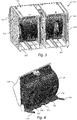
- the bin 100 is configured with two internal compartments 108, as seen in Fig. 3 , wherein the compartments 108 share a common front side 104 defined by a pivotal door 118 (discussed in greater detail below).
- Each compartment may have its own set of sides 105 and individual bottom wall 107, as depicted in Fig. 3 .
- adjacent compartments 108 within the same bin 100 may not have a dividing wall therebetween and may share a common bottom wall 107.
- the bin 100 may be configured with a single compartment 108 having its own pivotal door 118, sides 105 and bottom wall 107.
- each individual compartment 108 includes an electronic drive mechanism that dispenses the lottery tickets through a dispensing slot 116 in the back side 106 of the pivotal door 118.
- This drive mechanism may be variously configured.
- the drive mechanism includes a motor 112 that is operatively connected to a drive roller 114 that forms a nip with an opposite idler roller 115. The leading lottery ticket is conveyed through this nip and driven out through the dispensing slot 116 by the drive roller 114.
- the drive mechanism may be contained within the pivotal door 118, as depicted in the figures, or may be mounted in the housing 102 (e.g., within the individual compartment 108).
- the pivotal door 118 is movable between a fully closed position ( Figs. 7 and 8 ) and a fully open position relative to the housing 102 to allow the retail clerk to load new ticket packs into the compartment(s) 108.
- Fig. 5 depicts orientation of the pivotal door 118 in the fully open position
- Fig. 6 shows the pivotal door 118 in an intermediate position relative to the housing 102.
- the pivotal door 118 includes a back wall 120 that faces the compartment 108 and may have a generally arcuate shape as shown in the figures to accommodate the drive mechanism (motor 112 and rollers 114, 115) as well as a scanner and control components associated with the bin 100.
- the pivotal door 118 also includes a bottom frame member 122 that releasably mounts or attached to the housing 102, wherein the door 118 pivots relative to the bottom frame member 122. This configuration allows the entire pivotal door 118 to be readily removable from the housing 102 for repair or replacement.
- One or more spring-loaded, elongated tabs 124 are pivotally mounted and spring-loaded to the bottom frame member 122. These tabs 124 extend transversely from the bottom frame member 122 and are each individually biased (e.g., spring-loaded) against the back wall 120 in order to keep constant contact with the wall 120 in all opening angles of the pivotal door 118.
- the elongated tabs 124 have a length so as to be continuously engaged against the back wall 120 as the pivotal door 118 moves between the fully open and fully closed positions, as depicted in the figures. In this manner, the elongated tabs 124 define a bridge across the open hinge area between the pivotal door 118 and housing 102 that prevents the lottery tickets from moving into the hinge area and causing a jam or other condition that prevents the door from closing.
- a plurality of the elongated tabs 124 are spaced apart along the bottom frame member 122, with each compartment 108 in the bin 100 having two more of the tabs 124 configured therewith.
- the bottom frame member 122 may include opposite arms 126 at the opposite ends thereof that releasably engage with a bottom wall of the housing 102 at each compartment to mount the bottom frame 122 (and pivotal door 118) to the housing.
- the arms 126 may slide and lock into grooves within the housing 102.
- the entire pivotal door 118 is readily removable from the housing (and array) and is replaceable or interchangeable with other doors 118 in the array.
- the elongated tabs 124 may be variously configured.
- the tabs 124 have a length and shape such that, in the fully closed position of the pivotal door depicted in Figs. 7 and 8 , the elongated tabs 124 assumes a substantially vertical position within the housing compartment. This configuration presents little to no interference with the tickets within the compartment 108 during the dispense sequences, particularly if the tabs 124 are disposed essentially "under" the arcuate portion of the back wall 120 that extends into the compartment 108. In other words, the tabs 124 are vertical and at a location that does not extend as far into the compartment as the arcuate back wall 120.
- the back wall 120 includes a first rib 128 defined thereon that extends transversely from the wall 120.
- each elongated tab 124 is biased against a respective first rib 128 and slides against the rib 128 as the pivotal door 118 is moved between the fully closed and fully open positions.
- the first rib 128 has a minimal thickness and presents a minimal frictional contact surface against the elongated tab 124.
- the first rib 128 may be flanked by a pair of spaced-apart second ribs 130 that extend transversely from the back wall 120 of the door 118 into the compartment 108 beyond the first rib 128. These second ribs 130 are spaced-apart such that the elongated tab 124 slides against the first rib 128 between the second ribs 130, as particularly seen in Fig. 6 .
- the second ribs 130 may have a shape and length so as to be coplanar with the elongated tab 124 along at least an upper portion of the elongated tab 124, as particularly seen in Figs. 4 and 8 .
- This configuration of the second ribs 130 in conjunction with the elongated tab 124 and first rib 128 provides an essentially uninterrupted surface spanning across the hinge area as the pivotal door 118 is opened and closed, which eases loading of the ticket books. Very little care or attention is needed when closing the door 118 after loading the ticket book into the bin 12. Also, initial ticket book location in the bin 12 is not critical, as the door 118 configuration pushes the ticket book into the bin 12 as the door is closed while preventing pinching of tickets in the hinge area.
- the present invention encompasses any manner of lottery ticket dispenser array 10 having one or more of the dispenser bins 100 as embodied herein.
Landscapes
- Physics & Mathematics (AREA)
- General Physics & Mathematics (AREA)
- Credit Cards Or The Like (AREA)
Description
- Instant lottery tickets (e.g., "scratch-off' lottery tickets) are sold at many types of retail locations including, stores, such as grocery stores, general merchandise stores, and the like. Various configurations of lottery ticket dispensers have been proposed in the industry for this purpose, including electronic dispensers that automatically dispense a ticket from a bin or compartment upon receipt of an electronic command signal.
- For example,
U.S. Pat. No. 9,339,121 -
US Pat. Application Pub. No. 2017/0018148 describes a lottery ticket dispenser array having a plurality of individual interconnected individual bins, wherein each bin includes a multi-sided housing in which a pack of lottery tickets is stored. The stacked tickets are interconnected by a perforation line between adjacent tickets and a drive mechanism and scanner are configured within each bin. Upon receipt of a purchase signal, the drive mechanism dispenses the requisite number of tickets out of a slot in a back face or wall of the bin as the scanner reads the code printed on the ticket as it passes through the slot. The drive mechanism, dispensing slot, and control electronics are housed within the back wall, which is configured as a door that pivots between a fully closed position and a fully open position relative to the housing in order for an operator to load new ticket packs into the bin. - With the type of dispenser array wherein the individual bins (or two or more adjacent bins) have a pivotable door, as with the '148 application discussed above, a problem exists in that the bottom ticket layers tend to shift upon loading the ticket packs into the bin and can move into the area of the hinge line between the door and the compartment frame. When this occurs, the tickets jam the hinge line and prevent the door from closing. In addition, the tickets can become damaged (e.g., bent or torn) along the edges facing the door when the operator attempts to close the door, which may result in a subsequent dispensing jam when the ticket is engaged by the drive mechanism and fed through the dispensing slot.
- The present invention seeks to provide a pivotal door for one or more adjacent dispensing bins that minimizes the risk of tickets becoming lodged in the hinge area of the door.
- Objects and advantages of the invention will be set forth in part in the following description, or may be obvious from the description, or may be learned through practice of the invention.
- In accordance with the invention, a lottery ticket dispenser bin is provided as set out in the appended claim 1.
- Additional aspects are set out in the appended dependent claims.
- A full and enabling disclosure including the best mode of practicing the appended claims and directed to one of ordinary skill in the art is set forth more particularly in the remainder of the specification. The specification makes reference to the appended figures, in which:
-
Fig. 1 is a front perspective view of a conventional lottery ticket dispenser array that includes a plurality of individual ticket bins; -
Fig. 2 is a front perspective view of an embodiment of a lottery ticket dispenser bin in accordance with aspects of the invention; -
Fig. 3 is a back perspective view of the dispenser bin ofFig. 2 ; -
Fig. 4 is a back perspective view of a pivotal door assembly from the dispenser bin ofFig. 2 ; -
Fig. 5 is a side perspective view of the pivotal door assembly ofFig. 4 ; -
Fig. 6 is a side perspective view of the pivotal door assembly ofFig. 4 in an intermediate position relative to the bin housing; -
Fig. 7 is a side cut-away view of the pivotal door assembly and housing ofFig. 6 ; and -
Fig. 8 is a side perspective and cut-away view of the pivotal door assembly and housing ofFig. 7 . - Reference will now be made in detail to various and alternative exemplary embodiments and to the accompanying drawings, with like numerals representing substantially identical structural elements. Each example is provided by way of explanation, and not as a limitation. In fact, it will be apparent to those skilled in the art that modifications and variations can be made without departing from the scope or of the disclosure and claims.
-
Fig. 1 depicts a lotteryticket dispenser array 10 that includes a plurality ofindividual dispenser bins 12 in a stacked configuration. The architecture of eachbin 12 and theoverall array 10 can vary within the scope of the invention. For example, as depicted inFig. 1 , thedispenser array 10 may include a bottom row ofbins 12 having interconnectedbase structures 14. Eachbase structure 14 may include a male power plug and male data plug along one side (not visible inFig. 1 ), and afemale power port 16 andfemale data port 18 along the opposite side. The plugs and ports ofadjacent base structures 14 interconnect to essentially define a data bus running the length of thebase structures 14. An exposedpower port 16 anddata port 18 at one of the ends of the interconnectedbase structures 14 is available for connection with a power cord and a data cord from a system controller orlottery terminal 20. - Each of the
individual bins 12 includes amulti-sided housing 20 defining an internal space in which one or more compartments are defined. A stack or roll oflottery tickets 24 is stored in each compartment for subsequent dispensing through adispensing slot 28. Thelottery tickets 24 may be, for example, conventional instant scratch-off lottery tickets provided in the form of a stack of interconnectedtickets 24. In the depicted embodiments, thehousing 20 is a box-like structure having top and bottom walls, side walls 22, a front wall that faces outward towards a ticket purchaser, and a pivotal back wall orpanel 26 that swings open to provide access into thehousing 20 for loading the ticket stack. Eachbin 12 may include a male power/data connector on the top or bottom surface, and a corresponding female power/data connector on the opposite surface so that a plurality of thebins 12 can be vertically stacked and interconnected, as depicted inFig. 1 . -
Fig. 2 depicts an embodiment of a lotteryticket dispensing bin 100 that may be used with as a component of a dispenser array, such as thearray 10 inFig. 1 . Thebin 100 is configured for receipt and dispensing of pre-printed lottery tickets, such as conventional interconnected scratch-off lottery tickets, as discussed above. Theindividual bin 100 is defined by ahousing 102 having afront side 104 that faces a purchaser in operational use of the dispenser array, and anopposite back side 106 that faces the retail vendor or clerk. Eachbin 100 defines one ormore compartments 108 for receipt of the stack of interconnected lottery tickets in eachcompartment 108, such as a fan-folded stack or roll of interconnected lottery tickets. Eachbin 100 may contain a supply of different scratch-off lottery ticket games, or two or more bins may contain a respective supply of tickets for the same game. - In the embodiment of
Fig. 2 , thebin 100 is configured with twointernal compartments 108, as seen inFig. 3 , wherein thecompartments 108 share acommon front side 104 defined by a pivotal door 118 (discussed in greater detail below). Each compartment may have its own set ofsides 105 andindividual bottom wall 107, as depicted inFig. 3 . Alternatively,adjacent compartments 108 within thesame bin 100 may not have a dividing wall therebetween and may share acommon bottom wall 107. It should also be appreciated that thebin 100 may be configured with asingle compartment 108 having its ownpivotal door 118,sides 105 andbottom wall 107. - Referring to
Figs. 6 through 8 , eachindividual compartment 108 includes an electronic drive mechanism that dispenses the lottery tickets through adispensing slot 116 in theback side 106 of thepivotal door 118. This drive mechanism may be variously configured. For example, in the depicted embodiment, the drive mechanism includes amotor 112 that is operatively connected to adrive roller 114 that forms a nip with anopposite idler roller 115. The leading lottery ticket is conveyed through this nip and driven out through thedispensing slot 116 by thedrive roller 114. The drive mechanism may be contained within thepivotal door 118, as depicted in the figures, or may be mounted in the housing 102 (e.g., within the individual compartment 108). - Referring the figures in general, the
pivotal door 118 is movable between a fully closed position (Figs. 7 and 8 ) and a fully open position relative to thehousing 102 to allow the retail clerk to load new ticket packs into the compartment(s) 108.Fig. 5 depicts orientation of thepivotal door 118 in the fully open position, andFig. 6 shows thepivotal door 118 in an intermediate position relative to thehousing 102. - The
pivotal door 118 includes aback wall 120 that faces thecompartment 108 and may have a generally arcuate shape as shown in the figures to accommodate the drive mechanism (motor 112 androllers 114, 115) as well as a scanner and control components associated with thebin 100. Thepivotal door 118 also includes abottom frame member 122 that releasably mounts or attached to thehousing 102, wherein thedoor 118 pivots relative to thebottom frame member 122. This configuration allows the entirepivotal door 118 to be readily removable from thehousing 102 for repair or replacement. - One or more spring-loaded,
elongated tabs 124 are pivotally mounted and spring-loaded to thebottom frame member 122. Thesetabs 124 extend transversely from thebottom frame member 122 and are each individually biased (e.g., spring-loaded) against theback wall 120 in order to keep constant contact with thewall 120 in all opening angles of thepivotal door 118. Theelongated tabs 124 have a length so as to be continuously engaged against theback wall 120 as thepivotal door 118 moves between the fully open and fully closed positions, as depicted in the figures. In this manner, theelongated tabs 124 define a bridge across the open hinge area between thepivotal door 118 andhousing 102 that prevents the lottery tickets from moving into the hinge area and causing a jam or other condition that prevents the door from closing. - In the depicted embodiment, a plurality of the
elongated tabs 124 are spaced apart along thebottom frame member 122, with eachcompartment 108 in thebin 100 having two more of thetabs 124 configured therewith. - Referring particularly to
Figs. 4 and5 , thebottom frame member 122 may includeopposite arms 126 at the opposite ends thereof that releasably engage with a bottom wall of thehousing 102 at each compartment to mount the bottom frame 122 (and pivotal door 118) to the housing. For example, thearms 126 may slide and lock into grooves within thehousing 102. With this configuration, the entirepivotal door 118 is readily removable from the housing (and array) and is replaceable or interchangeable withother doors 118 in the array. - The
elongated tabs 124 may be variously configured. In the illustrated embodiment, thetabs 124 have a length and shape such that, in the fully closed position of the pivotal door depicted inFigs. 7 and 8 , theelongated tabs 124 assumes a substantially vertical position within the housing compartment. This configuration presents little to no interference with the tickets within thecompartment 108 during the dispense sequences, particularly if thetabs 124 are disposed essentially "under" the arcuate portion of theback wall 120 that extends into thecompartment 108. In other words, thetabs 124 are vertical and at a location that does not extend as far into the compartment as thearcuate back wall 120. - In the depicted embodiment, the
back wall 120 includes afirst rib 128 defined thereon that extends transversely from thewall 120. As shown in the various figures, eachelongated tab 124 is biased against a respectivefirst rib 128 and slides against therib 128 as thepivotal door 118 is moved between the fully closed and fully open positions. Thefirst rib 128 has a minimal thickness and presents a minimal frictional contact surface against theelongated tab 124. - In certain embodiments, the
first rib 128 may be flanked by a pair of spaced-apartsecond ribs 130 that extend transversely from theback wall 120 of thedoor 118 into thecompartment 108 beyond thefirst rib 128. Thesesecond ribs 130 are spaced-apart such that theelongated tab 124 slides against thefirst rib 128 between thesecond ribs 130, as particularly seen inFig. 6 . Thesecond ribs 130 may have a shape and length so as to be coplanar with theelongated tab 124 along at least an upper portion of theelongated tab 124, as particularly seen inFigs. 4 and8 . This configuration of thesecond ribs 130 in conjunction with theelongated tab 124 andfirst rib 128 provides an essentially uninterrupted surface spanning across the hinge area as thepivotal door 118 is opened and closed, which eases loading of the ticket books. Very little care or attention is needed when closing thedoor 118 after loading the ticket book into thebin 12. Also, initial ticket book location in thebin 12 is not critical, as thedoor 118 configuration pushes the ticket book into thebin 12 as the door is closed while preventing pinching of tickets in the hinge area. - It should be understood that the present invention encompasses any manner of lottery
ticket dispenser array 10 having one or more of thedispenser bins 100 as embodied herein. - The material particularly shown and described above is not meant to be limiting, but instead serves to show and teach various exemplary implementations of the present subject matter. As set forth in the attached claims, the scope of the present invention includes both combinations and sub-combinations of various features discussed herein.
Claims (9)
- A lottery ticket dispenser bin (100), comprising:a housing (102) having a front side (104) that faces a purchaser in operational use of a dispenser array (10), an opposite back side (106), and an internal space defining one or more compartments (108) for receipt of a supply of interconnected lottery tickets;each compartment (108) comprising an electronic drive mechanism that dispenses the lottery tickets through a dispensing slot (116) in the back side (106);a pivotal door (118) configured on the housing (102) and defining the back side (106), the pivotal door (118) movable between a fully closed position and a fully open position relative to the housing (102), the pivotal door (118) further comprising:a back wall (120), wherein the back wall (120) faces the compartment (108); anda bottom frame member (122) mounted to the housing (102), wherein the door (118) is configured to pivot relative to the bottom frame member (122);characterized by one or more spring-loaded, elongated tabs (124) pivotally mounted to the bottom frame member (122), the elongated tab (124) extending transversely from the bottom frame member (122) and biased against the back wall (120), the elongated tab (124) comprising a length so as to be continuously engaged against the back wall (120) as the pivotal door (118) moves between the fully open and fully closed positions; andwherein the elongated tab (124) defines a bridge that prevents the lottery tickets from moving into a hinge area between the housing (102) and the pivotal door (118).
- The lottery ticket dispenser bin (100) as in claim 1, further comprising a plurality of the elongated tabs (124) spaced apart along the bottom frame member (122).
- The lottery ticket dispenser bin (100) as in claim 1 or 2, wherein the bottom frame member (122) comprises arms (126) at opposite ends thereof, the arms (126) releasably engaging with the housing (102) to mount the bottom frame member (122) to the housing (102).
- The lottery ticket dispenser bin (100) as in any of claims 1 to 3, wherein in the fully closed position of the pivotal door (118), the elongated tab (124) assumes a substantially vertical position within the housing (102).
- The lottery ticket dispenser bin (100) as in any of claims 1 to 4, wherein the back wall (120) comprises a first rib (128) defined thereon, the elongated tab (124) biased against the first rib (128).
- The lottery ticket dispenser bin (100) as in claim 5, wherein the first rib (128) is flanked by a pair of second ribs (130) that extend transversely from the back wall (120) beyond the first rib (128), the pair of second ribs (130) spaced apart such that the elongated tab (124) slides against the first rib (128) between the second ribs (130).
- The lottery ticket dispenser bin (100) as in claim 6, wherein in the fully closed position of the pivotal door (118), the elongated tab (124) is biased against the first rib (128) and assumes a substantially vertical position within the housing (102), and the second ribs (130) are coplanar with the elongated tab (124) along at least an upper portion of the elongated tab (124).
- The lottery ticket dispenser bin (100) as in any of claims 1 to 7, wherein the pivotal door (118) extends across two adjacent compartments (108) and includes at least one of the elongated tabs (124) configured with each compartment (108).
- A lottery ticket dispenser array (10), comprising a plurality of the dispenser bins (100) in accordance with any of claims 1 to 8.
Applications Claiming Priority (1)
| Application Number | Priority Date | Filing Date | Title |
|---|---|---|---|
| US15/969,823 US10134244B1 (en) | 2018-05-03 | 2018-05-03 | Lottery ticket dispenser bin with pivotal door |
Publications (2)
| Publication Number | Publication Date |
|---|---|
| EP3564908A1 EP3564908A1 (en) | 2019-11-06 |
| EP3564908B1 true EP3564908B1 (en) | 2021-11-10 |
Family
ID=64176476
Family Applications (1)
| Application Number | Title | Priority Date | Filing Date |
|---|---|---|---|
| EP19172528.2A Active EP3564908B1 (en) | 2018-05-03 | 2019-05-03 | Lottery ticket dispenser bin with pivotal door |
Country Status (3)
| Country | Link |
|---|---|
| US (1) | US10134244B1 (en) |
| EP (1) | EP3564908B1 (en) |
| CA (1) | CA3042202C (en) |
Families Citing this family (3)
| Publication number | Priority date | Publication date | Assignee | Title |
|---|---|---|---|---|
| US20140353329A1 (en) * | 2013-05-31 | 2014-12-04 | Intralot S.A. - Integrated Lottery Systems And Services | Apparatuses for dispensing objects and methods of manufacturing and uses thereof |
| USD893915S1 (en) | 2018-09-20 | 2020-08-25 | Scientific Games International, Inc. | Lottery ticket module |
| US10860275B1 (en) * | 2018-12-19 | 2020-12-08 | Henschel-Steinau, Inc. | Modular display and dispensing system |
Family Cites Families (20)
| Publication number | Priority date | Publication date | Assignee | Title |
|---|---|---|---|---|
| US4336894A (en) * | 1980-06-02 | 1982-06-29 | Crye Leroy D | Ticket dispenser |
| EP0106742B1 (en) * | 1982-10-13 | 1986-07-09 | BAREGE, Jacqueline | Device for dispensing and severing a continuous web |
| US4858806A (en) * | 1988-02-01 | 1989-08-22 | Schafer Christopher E | Ticket display and dispenser |
| US5100038A (en) * | 1988-12-16 | 1992-03-31 | Schafer Christopher E | Ticket dispensing structure |
| US4995507A (en) * | 1988-12-16 | 1991-02-26 | Schafer Christopher E | Ticket dispensing structure |
| US5222624A (en) * | 1989-02-17 | 1993-06-29 | Donald Sutherland | Ticket dispenser machine and method |
| US5287980A (en) * | 1992-06-17 | 1994-02-22 | Eddy Associates, Inc. | Ticket dispenser assembly including interlocking dispenser units |
| US5399005A (en) * | 1993-09-07 | 1995-03-21 | Schafer Systems Inc. | Stackable locking display and dispensing structure |
| US6095624A (en) * | 1998-04-13 | 2000-08-01 | Scope Display And Box Company | Ticket dispenser |
| US7665394B2 (en) | 1998-04-14 | 2010-02-23 | Gtech Corporation | Ticket dispensing modules and method |
| US7032793B2 (en) | 1998-04-14 | 2006-04-25 | Gtech Corporation | Ticket dispensing device, installation and displays |
| US7467738B2 (en) | 2003-11-13 | 2008-12-23 | Gtech Corporation | Lottery ticket dispenser and ticket bin |
| US7014065B2 (en) | 2004-02-11 | 2006-03-21 | Schafer Systems Inc. | Dispenser for series-connected tickets |
| US20060016826A1 (en) * | 2004-07-21 | 2006-01-26 | Jensen Craig A | Coupling plate for stacking lottery ticket dispensers |
| US7383099B2 (en) | 2005-10-18 | 2008-06-03 | Pollard Banknote Limited Partnership | Apparatus for vending lottery tickets |
| GB2494706B (en) | 2011-09-19 | 2013-08-21 | Fastrak Retail Uk Ltd | Ticket dispenser |
| US9339121B2 (en) | 2012-08-13 | 2016-05-17 | Michael Siciliano | Inventory system and method for the prevention of scratch-off lottery ticket theft |
| GB2516074B (en) * | 2013-07-10 | 2018-04-25 | Fastrak Retail Uk Ltd | Ticket Dispenser |
| US10672234B2 (en) | 2015-07-17 | 2020-06-02 | Scientific Games International, Inc. | Method and system for enhanced lottery ticket accounting and sales with smart bin dispensers at a retail establishment |
| US9613337B1 (en) * | 2016-04-06 | 2017-04-04 | Scientific Games International, Inc. | Smart bin lottery ticket dispenser system with varying ticket size inserts and associated front panels |
-
2018
- 2018-05-03 US US15/969,823 patent/US10134244B1/en active Active
-
2019
- 2019-05-03 EP EP19172528.2A patent/EP3564908B1/en active Active
- 2019-05-03 CA CA3042202A patent/CA3042202C/en active Active
Also Published As
| Publication number | Publication date |
|---|---|
| EP3564908A1 (en) | 2019-11-06 |
| US10134244B1 (en) | 2018-11-20 |
| CA3042202C (en) | 2020-09-29 |
| CA3042202A1 (en) | 2019-11-03 |
Similar Documents
| Publication | Publication Date | Title |
|---|---|---|
| US7850257B2 (en) | Ticket dispensing device, installation and displays | |
| US7467738B2 (en) | Lottery ticket dispenser and ticket bin | |
| CA3042202C (en) | Lottery ticket dispenser bin with pivotal door | |
| ES2296290T3 (en) | AUTOMATIC CASHIER PRESENTING HALF-HALF TRAYS. | |
| US7121426B2 (en) | Apparatus for dispensing flat items | |
| US4858806A (en) | Ticket display and dispenser | |
| US5447366A (en) | Apparatus for dispensing discrete articles | |
| JP2018049512A (en) | vending machine | |
| EP3806051B1 (en) | Lottery ticket bin with pull-out drawer and ticket guide configuration | |
| US6598759B2 (en) | Dispensing container | |
| US5996841A (en) | Modular front loading rotary coin vending machine | |
| EP4535318B1 (en) | Lottery ticket vending machine | |
| EP3627436B1 (en) | Lottery ticket bin with pull-out drawer and ticket guide configuration | |
| JP3018785B2 (en) | Vending machine bag unloading device and bag | |
| US6644503B2 (en) | Single publication vending device | |
| CA3056095C (en) | Lottery ticket bin with pull-out drawer and folding cable configuration | |
| CA1126225A (en) | Single copy periodical dispenser | |
| JPS63229596A (en) | Vending machine | |
| GB2351073A (en) | Dispensing device for articles such as newspapers | |
| KR100217774B1 (en) | vending machine | |
| JP3156653B2 (en) | vending machine | |
| JP2533677Y2 (en) | Vending machine product storage device | |
| JPH0748609Y2 (en) | Paper sheet dispenser | |
| ZA200104940B (en) | Dispenser. |
Legal Events
| Date | Code | Title | Description |
|---|---|---|---|
| PUAI | Public reference made under article 153(3) epc to a published international application that has entered the european phase |
Free format text: ORIGINAL CODE: 0009012 |
|
| STAA | Information on the status of an ep patent application or granted ep patent |
Free format text: STATUS: THE APPLICATION HAS BEEN PUBLISHED |
|
| AK | Designated contracting states |
Kind code of ref document: A1 Designated state(s): AL AT BE BG CH CY CZ DE DK EE ES FI FR GB GR HR HU IE IS IT LI LT LU LV MC MK MT NL NO PL PT RO RS SE SI SK SM TR |
|
| AX | Request for extension of the european patent |
Extension state: BA ME |
|
| STAA | Information on the status of an ep patent application or granted ep patent |
Free format text: STATUS: REQUEST FOR EXAMINATION WAS MADE |
|
| 17P | Request for examination filed |
Effective date: 20200506 |
|
| RBV | Designated contracting states (corrected) |
Designated state(s): AL AT BE BG CH CY CZ DE DK EE ES FI FR GB GR HR HU IE IS IT LI LT LU LV MC MK MT NL NO PL PT RO RS SE SI SK SM TR |
|
| GRAP | Despatch of communication of intention to grant a patent |
Free format text: ORIGINAL CODE: EPIDOSNIGR1 |
|
| STAA | Information on the status of an ep patent application or granted ep patent |
Free format text: STATUS: GRANT OF PATENT IS INTENDED |
|
| INTG | Intention to grant announced |
Effective date: 20210528 |
|
| GRAS | Grant fee paid |
Free format text: ORIGINAL CODE: EPIDOSNIGR3 |
|
| GRAA | (expected) grant |
Free format text: ORIGINAL CODE: 0009210 |
|
| STAA | Information on the status of an ep patent application or granted ep patent |
Free format text: STATUS: THE PATENT HAS BEEN GRANTED |
|
| AK | Designated contracting states |
Kind code of ref document: B1 Designated state(s): AL AT BE BG CH CY CZ DE DK EE ES FI FR GB GR HR HU IE IS IT LI LT LU LV MC MK MT NL NO PL PT RO RS SE SI SK SM TR |
|
| REG | Reference to a national code |
Ref country code: GB Ref legal event code: FG4D |
|
| REG | Reference to a national code |
Ref country code: AT Ref legal event code: REF Ref document number: 1446786 Country of ref document: AT Kind code of ref document: T Effective date: 20211115 Ref country code: CH Ref legal event code: EP |
|
| REG | Reference to a national code |
Ref country code: DE Ref legal event code: R096 Ref document number: 602019009080 Country of ref document: DE |
|
| REG | Reference to a national code |
Ref country code: IE Ref legal event code: FG4D |
|
| REG | Reference to a national code |
Ref country code: NL Ref legal event code: FP |
|
| REG | Reference to a national code |
Ref country code: SE Ref legal event code: TRGR |
|
| REG | Reference to a national code |
Ref country code: LT Ref legal event code: MG9D |
|
| REG | Reference to a national code |
Ref country code: AT Ref legal event code: MK05 Ref document number: 1446786 Country of ref document: AT Kind code of ref document: T Effective date: 20211110 |
|
| PG25 | Lapsed in a contracting state [announced via postgrant information from national office to epo] |
Ref country code: RS Free format text: LAPSE BECAUSE OF FAILURE TO SUBMIT A TRANSLATION OF THE DESCRIPTION OR TO PAY THE FEE WITHIN THE PRESCRIBED TIME-LIMIT Effective date: 20211110 Ref country code: LT Free format text: LAPSE BECAUSE OF FAILURE TO SUBMIT A TRANSLATION OF THE DESCRIPTION OR TO PAY THE FEE WITHIN THE PRESCRIBED TIME-LIMIT Effective date: 20211110 Ref country code: FI Free format text: LAPSE BECAUSE OF FAILURE TO SUBMIT A TRANSLATION OF THE DESCRIPTION OR TO PAY THE FEE WITHIN THE PRESCRIBED TIME-LIMIT Effective date: 20211110 Ref country code: BG Free format text: LAPSE BECAUSE OF FAILURE TO SUBMIT A TRANSLATION OF THE DESCRIPTION OR TO PAY THE FEE WITHIN THE PRESCRIBED TIME-LIMIT Effective date: 20220210 Ref country code: AT Free format text: LAPSE BECAUSE OF FAILURE TO SUBMIT A TRANSLATION OF THE DESCRIPTION OR TO PAY THE FEE WITHIN THE PRESCRIBED TIME-LIMIT Effective date: 20211110 |
|
| PG25 | Lapsed in a contracting state [announced via postgrant information from national office to epo] |
Ref country code: IS Free format text: LAPSE BECAUSE OF FAILURE TO SUBMIT A TRANSLATION OF THE DESCRIPTION OR TO PAY THE FEE WITHIN THE PRESCRIBED TIME-LIMIT Effective date: 20220310 Ref country code: PT Free format text: LAPSE BECAUSE OF FAILURE TO SUBMIT A TRANSLATION OF THE DESCRIPTION OR TO PAY THE FEE WITHIN THE PRESCRIBED TIME-LIMIT Effective date: 20220310 Ref country code: PL Free format text: LAPSE BECAUSE OF FAILURE TO SUBMIT A TRANSLATION OF THE DESCRIPTION OR TO PAY THE FEE WITHIN THE PRESCRIBED TIME-LIMIT Effective date: 20211110 Ref country code: NO Free format text: LAPSE BECAUSE OF FAILURE TO SUBMIT A TRANSLATION OF THE DESCRIPTION OR TO PAY THE FEE WITHIN THE PRESCRIBED TIME-LIMIT Effective date: 20220210 Ref country code: LV Free format text: LAPSE BECAUSE OF FAILURE TO SUBMIT A TRANSLATION OF THE DESCRIPTION OR TO PAY THE FEE WITHIN THE PRESCRIBED TIME-LIMIT Effective date: 20211110 Ref country code: HR Free format text: LAPSE BECAUSE OF FAILURE TO SUBMIT A TRANSLATION OF THE DESCRIPTION OR TO PAY THE FEE WITHIN THE PRESCRIBED TIME-LIMIT Effective date: 20211110 Ref country code: GR Free format text: LAPSE BECAUSE OF FAILURE TO SUBMIT A TRANSLATION OF THE DESCRIPTION OR TO PAY THE FEE WITHIN THE PRESCRIBED TIME-LIMIT Effective date: 20220211 Ref country code: ES Free format text: LAPSE BECAUSE OF FAILURE TO SUBMIT A TRANSLATION OF THE DESCRIPTION OR TO PAY THE FEE WITHIN THE PRESCRIBED TIME-LIMIT Effective date: 20211110 |
|
| PG25 | Lapsed in a contracting state [announced via postgrant information from national office to epo] |
Ref country code: SM Free format text: LAPSE BECAUSE OF FAILURE TO SUBMIT A TRANSLATION OF THE DESCRIPTION OR TO PAY THE FEE WITHIN THE PRESCRIBED TIME-LIMIT Effective date: 20211110 Ref country code: SK Free format text: LAPSE BECAUSE OF FAILURE TO SUBMIT A TRANSLATION OF THE DESCRIPTION OR TO PAY THE FEE WITHIN THE PRESCRIBED TIME-LIMIT Effective date: 20211110 Ref country code: RO Free format text: LAPSE BECAUSE OF FAILURE TO SUBMIT A TRANSLATION OF THE DESCRIPTION OR TO PAY THE FEE WITHIN THE PRESCRIBED TIME-LIMIT Effective date: 20211110 Ref country code: EE Free format text: LAPSE BECAUSE OF FAILURE TO SUBMIT A TRANSLATION OF THE DESCRIPTION OR TO PAY THE FEE WITHIN THE PRESCRIBED TIME-LIMIT Effective date: 20211110 Ref country code: DK Free format text: LAPSE BECAUSE OF FAILURE TO SUBMIT A TRANSLATION OF THE DESCRIPTION OR TO PAY THE FEE WITHIN THE PRESCRIBED TIME-LIMIT Effective date: 20211110 Ref country code: CZ Free format text: LAPSE BECAUSE OF FAILURE TO SUBMIT A TRANSLATION OF THE DESCRIPTION OR TO PAY THE FEE WITHIN THE PRESCRIBED TIME-LIMIT Effective date: 20211110 |
|
| REG | Reference to a national code |
Ref country code: DE Ref legal event code: R097 Ref document number: 602019009080 Country of ref document: DE |
|
| PLBE | No opposition filed within time limit |
Free format text: ORIGINAL CODE: 0009261 |
|
| STAA | Information on the status of an ep patent application or granted ep patent |
Free format text: STATUS: NO OPPOSITION FILED WITHIN TIME LIMIT |
|
| 26N | No opposition filed |
Effective date: 20220811 |
|
| PG25 | Lapsed in a contracting state [announced via postgrant information from national office to epo] |
Ref country code: AL Free format text: LAPSE BECAUSE OF FAILURE TO SUBMIT A TRANSLATION OF THE DESCRIPTION OR TO PAY THE FEE WITHIN THE PRESCRIBED TIME-LIMIT Effective date: 20211110 |
|
| PG25 | Lapsed in a contracting state [announced via postgrant information from national office to epo] |
Ref country code: SI Free format text: LAPSE BECAUSE OF FAILURE TO SUBMIT A TRANSLATION OF THE DESCRIPTION OR TO PAY THE FEE WITHIN THE PRESCRIBED TIME-LIMIT Effective date: 20211110 |
|
| REG | Reference to a national code |
Ref country code: CH Ref legal event code: PL |
|
| REG | Reference to a national code |
Ref country code: BE Ref legal event code: MM Effective date: 20220531 |
|
| PG25 | Lapsed in a contracting state [announced via postgrant information from national office to epo] |
Ref country code: MC Free format text: LAPSE BECAUSE OF FAILURE TO SUBMIT A TRANSLATION OF THE DESCRIPTION OR TO PAY THE FEE WITHIN THE PRESCRIBED TIME-LIMIT Effective date: 20211110 Ref country code: LU Free format text: LAPSE BECAUSE OF NON-PAYMENT OF DUE FEES Effective date: 20220503 Ref country code: LI Free format text: LAPSE BECAUSE OF NON-PAYMENT OF DUE FEES Effective date: 20220531 Ref country code: CH Free format text: LAPSE BECAUSE OF NON-PAYMENT OF DUE FEES Effective date: 20220531 |
|
| PG25 | Lapsed in a contracting state [announced via postgrant information from national office to epo] |
Ref country code: IE Free format text: LAPSE BECAUSE OF NON-PAYMENT OF DUE FEES Effective date: 20220503 |
|
| PG25 | Lapsed in a contracting state [announced via postgrant information from national office to epo] |
Ref country code: BE Free format text: LAPSE BECAUSE OF NON-PAYMENT OF DUE FEES Effective date: 20220531 |
|
| REG | Reference to a national code |
Ref country code: DE Ref legal event code: R081 Ref document number: 602019009080 Country of ref document: DE Owner name: SCIENTIFIC GAMES, LLC, ALPHARETTA, US Free format text: FORMER OWNER: SCIENTIFIC GAMES HOLDINGS LTD., BALLYMAHON, LONGFORD, IE |
|
| REG | Reference to a national code |
Ref country code: GB Ref legal event code: 732E Free format text: REGISTERED BETWEEN 20230615 AND 20230621 |
|
| REG | Reference to a national code |
Ref country code: NL Ref legal event code: PD Owner name: SCIENTIFIC GAMES, LLC; US Free format text: DETAILS ASSIGNMENT: CHANGE OF OWNER(S), ASSIGNMENT; FORMER OWNER NAME: SCIENTIFIC GAMES HOLDINGS LIMITED Effective date: 20230711 |
|
| PG25 | Lapsed in a contracting state [announced via postgrant information from national office to epo] |
Ref country code: HU Free format text: LAPSE BECAUSE OF FAILURE TO SUBMIT A TRANSLATION OF THE DESCRIPTION OR TO PAY THE FEE WITHIN THE PRESCRIBED TIME-LIMIT; INVALID AB INITIO Effective date: 20190503 |
|
| PG25 | Lapsed in a contracting state [announced via postgrant information from national office to epo] |
Ref country code: MK Free format text: LAPSE BECAUSE OF FAILURE TO SUBMIT A TRANSLATION OF THE DESCRIPTION OR TO PAY THE FEE WITHIN THE PRESCRIBED TIME-LIMIT Effective date: 20211110 Ref country code: CY Free format text: LAPSE BECAUSE OF FAILURE TO SUBMIT A TRANSLATION OF THE DESCRIPTION OR TO PAY THE FEE WITHIN THE PRESCRIBED TIME-LIMIT Effective date: 20211110 |
|
| PG25 | Lapsed in a contracting state [announced via postgrant information from national office to epo] |
Ref country code: TR Free format text: LAPSE BECAUSE OF FAILURE TO SUBMIT A TRANSLATION OF THE DESCRIPTION OR TO PAY THE FEE WITHIN THE PRESCRIBED TIME-LIMIT Effective date: 20211110 |
|
| PG25 | Lapsed in a contracting state [announced via postgrant information from national office to epo] |
Ref country code: MT Free format text: LAPSE BECAUSE OF FAILURE TO SUBMIT A TRANSLATION OF THE DESCRIPTION OR TO PAY THE FEE WITHIN THE PRESCRIBED TIME-LIMIT Effective date: 20211110 |
|
| PGFP | Annual fee paid to national office [announced via postgrant information from national office to epo] |
Ref country code: NL Payment date: 20250423 Year of fee payment: 7 |
|
| PGFP | Annual fee paid to national office [announced via postgrant information from national office to epo] |
Ref country code: DE Payment date: 20250423 Year of fee payment: 7 |
|
| PGFP | Annual fee paid to national office [announced via postgrant information from national office to epo] |
Ref country code: IT Payment date: 20250514 Year of fee payment: 7 |
|
| PGFP | Annual fee paid to national office [announced via postgrant information from national office to epo] |
Ref country code: FR Payment date: 20250422 Year of fee payment: 7 |
|
| PGFP | Annual fee paid to national office [announced via postgrant information from national office to epo] |
Ref country code: SE Payment date: 20250513 Year of fee payment: 7 |
|
| PGFP | Annual fee paid to national office [announced via postgrant information from national office to epo] |
Ref country code: GB Payment date: 20260320 Year of fee payment: 8 |