EP3564732A1 - Head-mounted display device - Google Patents
Head-mounted display device Download PDFInfo
- Publication number
- EP3564732A1 EP3564732A1 EP19164103.4A EP19164103A EP3564732A1 EP 3564732 A1 EP3564732 A1 EP 3564732A1 EP 19164103 A EP19164103 A EP 19164103A EP 3564732 A1 EP3564732 A1 EP 3564732A1
- Authority
- EP
- European Patent Office
- Prior art keywords
- positioning structure
- cushion
- pair
- head
- user
- Prior art date
- Legal status (The legal status is an assumption and is not a legal conclusion. Google has not performed a legal analysis and makes no representation as to the accuracy of the status listed.)
- Granted
Links
Images






Classifications
-
- A—HUMAN NECESSITIES
- A42—HEADWEAR
- A42B—HATS; HEAD COVERINGS
- A42B3/00—Helmets; Helmet covers ; Other protective head coverings
- A42B3/04—Parts, details or accessories of helmets
- A42B3/10—Linings
- A42B3/14—Suspension devices
- A42B3/145—Size adjustment devices
-
- G—PHYSICS
- G02—OPTICS
- G02B—OPTICAL ELEMENTS, SYSTEMS OR APPARATUS
- G02B27/00—Optical systems or apparatus not provided for by any of the groups G02B1/00 - G02B26/00, G02B30/00
- G02B27/01—Head-up displays
- G02B27/017—Head mounted
- G02B27/0176—Head mounted characterised by mechanical features
-
- A—HUMAN NECESSITIES
- A42—HEADWEAR
- A42B—HATS; HEAD COVERINGS
- A42B3/00—Helmets; Helmet covers ; Other protective head coverings
- A42B3/04—Parts, details or accessories of helmets
- A42B3/08—Chin straps or similar retention devices
- A42B3/085—Occipital retention systems
-
- A—HUMAN NECESSITIES
- A42—HEADWEAR
- A42B—HATS; HEAD COVERINGS
- A42B3/00—Helmets; Helmet covers ; Other protective head coverings
- A42B3/04—Parts, details or accessories of helmets
- A42B3/10—Linings
- A42B3/14—Suspension devices
-
- G—PHYSICS
- G06—COMPUTING OR CALCULATING; COUNTING
- G06F—ELECTRIC DIGITAL DATA PROCESSING
- G06F1/00—Details not covered by groups G06F3/00 - G06F13/00 and G06F21/00
- G06F1/16—Constructional details or arrangements
- G06F1/1613—Constructional details or arrangements for portable computers
- G06F1/163—Wearable computers, e.g. on a belt
Definitions
- the application relates to a head-mounted display device, and particularly relates to a head-mounted display device capable of improving wearing comfort.
- the application is directed to a head-mounted display device, which is capable of matching with head shapes of different users, such that the users can more stably wear the head-mounted display device to improve wearing comfort of the user.
- the application provides a head-mounted display device including a wearable assembly, at least one cushion and at least one adjustable fixing assembly.
- the wearable assembly is adapted to be worn on a head of a user.
- the at least one cushion is adapted to contact the head of the user, and is floatingly connected to the wearable assembly.
- the at least one adjustable fixing assembly includes a first positioning structure and a second positioning structure. The first positioning structure is connected to the wearable assembly, and the second positioning structure is connected to the at least one cushion. A structural interference generated between the first positioning structure and the second positioning structure positions the at least one cushion to the wearable assembly.
- the wearable assembly is adapted to be worn on the head of the user
- the at least one cushion is floatingly connected to the wearable assembly, and is adapted to contact the head of the user when the wearable assembly is worn on the head of the user.
- the structural interference generated between the first positioning structure and the second positioning structure positions the at least one cushion to the wearable assembly.
- the head-mounted display device may be matched to head shapes of different users, such that the users may more stably wear the head-mounted display devices to improve wearing comfort of the user wearing the head-mounted display device.
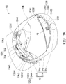
- FIG. 1A is a schematic three-dimensional view of a head-mounted display device according to an embodiment of the application.
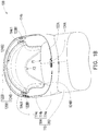
- FIG. 1B is a schematic three-dimensional view of the head-mounted display device of FIG. 1A viewing from another viewing angle.
- the head-mounted display device 100 includes a wearable assembly 110, at least one cushion and an adjustable fixing assembly.
- the at least one cushion (for example, a first cushion 120A and a second cushion 120B of FIG. 3A ) is floatingly connected to the wearable assembly 110.
- the wearable assembly 110 may be worn on a head of a user, and the at least one cushion is adapted to contact the head of the user when the wearable assembly 110 is worn on the head of the user, and the at least one cushion may be positioned to the wearable assembly 110 through the at least one adjustable fixing assembly (for example, a first adjustable fixing assembly 130A and a second adjustable fixing assembly 130B shown in FIG. 3A ).
- the head-mounted display device 100 may be matched to head shapes of different users, such that the users may more stably wear the head-mounted display device 100 to improve wearing comfort of the user wearing the head-mounted display device 100.
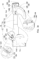
- FIG. 3A is a schematic cross-sectional view of the cushions of the head-mounted display device of FIG. 1A before being subjected to external forces.
- first sliding channels 114a1, second sliding channels 114c1, first sliding portions 122A1 and second sliding portions 122B1 are shown by dashed lines in FIG. 3A .
- the wearable assembly 110 includes a main body 112 and a headband assembly 114 connected to the main body 112.
- a display 112a may be built in or additionally configured to the main body 112.
- the display 112a may project display images to the eyes of the user when the user wears the headband assembly 114.
- the headband assembly 114 includes an eye contact portion 114a, a pair of extension portions 114b respectively connected to two opposite ends of the eye contact portion 114a, and a rotation mechanism 114c coupled to the pair of extension portions 114b.
- the user may cover the eye contact portion 114a on the two eyes of the user, and rotates the rotation mechanism 114c to drive the pair of extension portions 114b to tighten or loosen, so as to adjust a total length of the pair of extension portions 114b, and thus the wearable assembly 110 is adapted to be worn on the head of the user.
- FIG. 2A is a schematic partial cross-sectional view of the head-mounted display device of FIG. 1A .
- FIG. 2B is a schematic partial cross-sectional view of the head-mounted display device of FIG. 1B .
- the at least one cushion may include the first cushion 120A and the second cushion 120B.
- the first cushion 120A includes a first support portion 122A made of a rigid material, and a first buffer portion 124A made of a soft material, the first support portion 122A is used for supporting, and the first buffer portion 124A may contact the head of the user to improve comfort of the user wearing the head-mounted display device 100.
- the first support portion 122A includes a pair of first sliding portions 122A1, and the pair of the first sliding portions 122A1 are respectively connected to two opposite ends of the first support portion 122A.
- the eye contact portion 114a has a pair of first sliding channels 114a1 corresponding to the pair of first sliding portions 122A1, and the pair of first sliding portions 122A1 are movably disposed in the pair of first sliding channels 114a1, such that the first cushion 120A is floatingly connected to the wearable assembly 110.
- the second cushion 120B includes a second support portion 122B made of the rigid material, and a second buffer portion 124BA made of the soft material, the second support portion 122B is used for supporting, and the second buffer portion 124B may contact the head of the user to improve comfort of the user wearing the head-mounted display device 100.
- the second support portion 122B includes a pair of second sliding portions 122B1, and the pair of the second sliding portions 122B1 are respectively connected to two opposite ends of the second support portion 122B.
- the rotation mechanism 114c has a pair of second sliding channels 114c1 corresponding to the pair of second sliding portions 122B1, and the pair of second sliding portions 122B1 are movably disposed in the pair of second sliding channels 114c1, such that the second cushion 120B is floatingly connected to the wearable assembly 110.
- first sliding portions 122A1 and the second sliding portions 122B1 are, for example, spherical structures, though in other embodiments, the first sliding portions and the second sliding portions may also be columnar structures, which is not limited here, as long as the first sliding portions 122A1 may be slid and rotated in the first sliding channel 114a1, and the second sliding portions 122B1 may be slid and rotated in the second sliding channel 114c1.
- the number of the cushions may be increased or decreased according to an actual requirement, and the sliding portions and the sliding channels may also be increased or decreased according to the number of the cushions.
- the cushions may be disposed at any place of the wearable assembly 110 according to an actual requirement, for example, at least one pair of the sliding channels may be disposed on the eye contact portion 114a, the extension portion 114b or the rotation mechanism 114c, such that the cushions are floatingly connected to the eye contact portion 114a, the extension portion 114b or the rotation mechanism 114c through coordination between the sliding portions and the sliding channels, so as to contact different positions of the user's head.
- the wearable assembly 110 may have at least one pair of sliding channels, at least one cushion and at least one pair of sliding portions corresponding to the at least one pair of sliding channels, the pair of sliding portions are located at two opposite ends of the at least one cushion, and the pair of sliding portions are movably disposed in the pair of sliding channels, such that the at least one cushion is floatingly connected to the wearable assembly 110.
- the at least one adjustable fixing assembly may include a first adjustable fixing assembly 130A and a second adjustable fixing assembly 130B.
- the first adjustable fixing assembly 130A includes a first positioning structure (for example, a first interference portion 132A in FIG. 3A ) and a second positioning structure (for example, a second interference portion 134A in FIG. 3A ), the first positioning structure is connected to the eye contact portion 114a, and the second positioning structure is connected to the first cushion 120A.
- the second adjustable fixing assembly 130B includes a third positioning structure (for example, a third interference portion 132B in FIG. 3A ) and a fourth positioning structure (for example, a fourth interference portion 134B in FIG. 3A ), the third positioning structure is connected to the rotation mechanism 114c, and the fourth positioning structure is connected to the second cushion 120B.
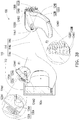
- FIG. 3B is a schematic diagram of the cushions of the head-mounted display device of FIG. 3A positioned to the wearable assembly after being subjected to the external forces.
- the first sliding channels 114a1, the second sliding channels 114c1, the first sliding portions 122A1 and the second sliding portions 122B1 are shown by dashed lines in FIG. 3B .
- the first buffer portion 124A of the first cushion 120A has a first upper side 124A1 and a first lower side 124A2 opposite to each other.
- the second buffer portion 124B of the second cushion 120B has a second lower side 124B1 and a second upper side 124B2 opposite to each other.
- FIG. 3A illustrates a state that the first cushion 120A is not subjected to a first external force F1, and the second cushion 120B is not subjected to a second external force F2.
- the first upper side 124A1 of the first cushion 120A may contact a frontal bone of the user
- the second lower side 124B1 of the second cushion 120B may contact an occipital bone of the user.
- the user may rotate the rotation mechanism 114c to drive the pair of extension portions 114b to tighten, such that a total length of the pair of extension portions 114b is shortened, and the first cushion 120A is accordingly subjected to the first external force F1, and the second cushion 120B is subjected to the second external force F2.
- the first positioning structure includes a first interference portion 132A
- the second positioning structure includes a plurality of second interference portions 134A corresponding to the first interference portion 132A.
- the third positioning structure includes a third interference portion 132B
- the fourth positioning structure includes a plurality of fourth interference portions 134B corresponding to the third interference portion 132B.
- FIG. 3B illustrates the first cushion 120A of FIG. 3A subjected to the first external force F1 is only translated towards the eye contact portion 114a without being rotated, and the second cushion 120B subjected to the second external force F2 is only translated towards the rotation mechanism 114c without being rotated.
- the first cushion 120A When the first cushion 120A is subjected to the first external force F1 to drive the second positioning structure to move towards the first positioning structure relative to the eye contact portion 114a and the two opposite ends of the first cushion 120A are translated towards each other under the function of the first external force F1 to make the first interference portion 132A to be moved between two adjacent second interference portions 134A to engage with the two adjacent second interference portions 134A, the mutual engagement between the first positioning structure and the second positioning structure positions the first cushion 120A to the wearable assembly 110.
- the first positioning structure and the second positioning structure are structurally interfered to position the first cushion 120A to the eye contact portion 114a, the first upper side 124A1 and the first lower side 124A2 of the first cushion 120A contact the frontal bone of the user at the same time, so that the first cushion 120A is matched with a head shape of the user, which avails the user more stably wearing the head-mounted display device 100 on the head, and improving comfort of the user wearing the head-mounted display device 100.
- the second cushion 120B is subjected to the second external force F2 to drive the fourth positioning structure to move towards the third positioning structure relative to the rotation mechanism 114c and the two opposite ends of the second cushion 120B are translated towards each other under the function of the second external force F2 to make the third interference portion 132B to be moved between two adjacent fourth interference portions 134B to engage with one of the two adjacent fourth interference portions 134B, the mutual engagement between the third positioning structure and the fourth positioning structure positions the second cushion 120B to the wearable assembly 110.
- the second lower side 124B1 and the second upper side 124B2 of the second cushion 120B contact the occipital bone of the user at the same time, so that the second cushion 120B is matched with a head shape of the user, which avails the user more stably wearing the head-mounted display device 100 on the head, and improving comfort of the user wearing the head-mounted display device 100.
- FIG. 4A is a schematic cross-sectional view of the cushions of the head-mounted display device of FIG. 1A rotated relative to the wearable assembly after being subjected to the external force.
- FIG. 4B is a schematic cross-sectional view of the cushions of the head-mounted display device of FIG. 4A positioned to the wearable assembly after being subjected to the external force.
- the first sliding channels 114a1, the second sliding channels 114c1, the first sliding portions 122A1 and the second sliding portions 122B1 are shown by dashed lines in FIG. 4A and FIG. 4B .
- FIG. 4A illustrates a schematic diagram that the first cushion 120A of FIG.
- the first cushion 120A is subjected to the first external force F1 to drive the second positioning structure to move towards the first positioning structure relative to the eye contact portion 114a and the two opposite ends of the first cushion 120A are translated towards each other under the function of the first external force F1
- the first cushion 120A is rotated relative to the eye contact portion 114a to make the first interference portion 132A to be moved between two adjacent second interference portions 134A to engage with the two adjacent second interference portions 134A
- the mutual engagement between the first positioning structure and the second positioning structure positions the first cushion 120A to the wearable assembly 110.
- the first positioning structure and the second positioning structure are structurally interfered to position the first cushion 120A to the eye contact portion 114a, the first upper side 124A1 and the first lower side 124A2 of the first cushion 120A contact the frontal bone of the user at the same time.
- the first cushion 120A may be rotated by a different angle relative to the eye contact portion 114a in response to the head shapes of different users, so that the head-mounted display device 100 may be matched with head shapes of different users, which avails the user more stably wearing the head-mounted display device 100 on the head, and improving comfort of the user wearing the head-mounted display device 100.
- the second cushion 120B is subjected to the second external force F2 to drive the fourth positioning structure to move towards the third positioning structure relative to the rotation mechanism 114c and the two opposite ends of the second cushion 120B are translated towards each other under the function of the second external force F2, and the second cushion 120B is rotated relative to the rotation mechanism 114c to make the third interference portion 132B to be moved between two adjacent fourth interference portions 134B to engage with one of the two adjacent fourth interference portions 134B, the mutual engagement between the third positioning structure and the fourth positioning structure positions the second cushion 120B to the wearable assembly 110.
- the second cushion 120B may be rotated by a different angle relative to the rotation mechanism 114c in response to the head shapes of different users, so that the head-mounted display device 100 may be matched with head shapes of different users, which avails the head-mounted display device 100 can be more stably worn on the heads of different users, and improving comfort of the user wearing the head-mounted display device 100.
- the number and configuration positions of the cushions may be adjusted according to an actual requirement.
- the head-mounted display device 100 may be only configured with a single first cushion 120A or a single second cushion 120B, or configured with both of the first cushion 120A and the second cushion 120B.
- the cushions may be configured on at least one of the eye contact portion 114a, the extension portion 114b and the rotation mechanism 114c to contact different parts of the user's head.
- first support portion 122A, the first sliding portion 122A1 and the second interference portion 134A of the second positioning structure are, for example, formed integrally, but may also be assembled from different members in other embodiments.
- second support portion 122B, the second sliding portion 122B1 and the fourth interference portion 134B of the fourth positioning structure are, for example, formed integrally, but may also be assembled from different members in other embodiments.
- the eye contact portion 114a includes a first position limiting portion 114a2
- the first support portion 122A of the first cushion 120A includes a second position limiting portion 122A2 corresponding to the first position limiting portion 114a2
- the first position limiting portion 114a2 and the second position limiting portion 122A2 are configured to limit rotation of the first cushion 120A relative to the eye contact portion 114a.
- structures the same as the first position limiting portion 114a2 and the second position limiting portion 122A2 may also be configured between the second cushion 120B and the rotation mechanism 114c to limit rotation of the second cushion 120B relative to the rotation mechanism 114c, and details thereof are not repeated.
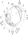
- FIG. 5 is a schematic three-dimensional view of a head-mounted display device according to another embodiment of the application.
- FIG. 6A is a schematic cross-sectional view of cushions of the head-mounted display device of FIG. 5 being not subjected to external forces.
- FIG. 6B is a schematic diagram of the cushions of the head-mounted display device of FIG. 6A positioned to the wearable assembly after being subjected to the external forces.
- the first sliding channels 214a1, the second sliding channels 214c1, the first sliding portions 222A1 and the second sliding portions 222B1 are shown by dashed lines in FIG. 6A and FIG. 6B .
- the head-mounted display device 200 includes a wearable assembly 210, a first cushion 220A, a second cushion 220B, a first adjustable fixing assembly 230A and a second adjustable fixing assembly 230B.
- the wearable assembly 210 includes a main body 212 and a headband assembly 214 connected to the main body 212.
- the headband assembly 214 includes an eye contact portion 214a capable of covering the two eyes of the user, a pair of extension portions 214b respectively connected to two opposite ends of the eye contact portion 214a, and a rotation mechanism 214c coupled to the pair of extension portions 214b, and the rotation mechanism 214c is adapted to rotate and drive the pair of extension portions 214b to tighten or loosen, so as to increase or decrease a total length of the pair of extension portions 214b.
- a display 212a may be built in or additionally assembled in the main body 212, and the display 212a may project display images to the eyes of the user.
- the eye contact portion 214a has a pair of first sliding channels 214a1.
- the first cushion 220A includes a first support portion 222A and a first buffer portion 224A connected to the first support portion 222A.
- the first support portion 222A includes a pair of first sliding portions 222A1 corresponding to the pair of first sliding channels 214a1, the pair of first sliding portions 222A1 are movably disposed in the pair of first sliding channels 214a1, and the first sliding portions 222A1 are, for example, spherical structures, but not limited thereto.
- the first buffer portion 224A is configured to contact the frontal bone of the user, and has a first upper side 224A1 and a first lower side 224A2 opposite to each other.
- the rotation mechanism 214c has a pair of second sliding channels 214c1.
- the second cushion 220B includes a second support portion 222B and a second buffer portion 224B connected to the second support portion 222B.
- the second support portion 222B includes a pair of second sliding portions 222B1 corresponding to the pair of second sliding channels 214c1, the pair of second sliding portions 222B1 are movably disposed in the pair of second sliding channels 214c1, and the second sliding portions 222B1 are, for example, spherical structures, but not limited thereto.
- the second buffer portion 224B is configured to contact the occipital bone of the user, and has a second lower side 224B1 and a second upper side 224B2 opposite to each other.
- the first upper side 224A1 of the first buffer portion 224A contacts the frontal bone of the user
- the second lower side 224B1 of the second buffer portion 224B contacts the occipital bone of the user.
- the first adjustable fixing assembly 230A includes a first positioning structure (for example, a rough surface 232A in FIG. 6A ) and a second positioning structure (for example, another rough surface 234A in FIG. 6A ), the first positioning structure is connected to the eye contact portion 214a of the headband assembly 214, and the second positioning structure is connected to the first support portion 222A of the first cushion 220A.
- the first positioning structure includes a rough surface 232A
- the second positioning structure includes another rough surface 234A corresponding to the first positioning structure.
- the second adjustable fixing assembly 230B includes a third positioning structure (for example, a rough surface 232B in FIG. 6A ) and a fourth positioning structure (for example, another rough surface 234B in FIG. 6A ), the third positioning structure is connected to the rotation mechanism 214c of the headband assembly 214, and the fourth positioning structure is connected to the second support portion 222B of the second cushion 220B.
- the third positioning structure includes a rough surface 232B, and the fourth positioning structure includes another rough surface 234B corresponding to the third positioning structure.
- first cushion 220A When the first cushion 220A is subjected to the first external force F1 to drive the second positioning structure to move towards the first positioning structure relative to the eye contact portion 214a of the wearable assembly 210 and rotate relative to the eye contact portion 214a of the wearable assembly 210 to make the other rough surface 234A to contact the rough surface 232A, friction generated between the first positioning structure and the second positioning structure positions the first cushion 220A to the eye contact portion 214a of the wearable assembly 210, and the first upper side 224A1 and the first lower side 224A2 of the first cushion 220A contact the frontal bone of the user at the same time.
- the head-mounted display device 200 may be matched with different head shapes of the users, which avails the user more stably wearing the head-mounted display device 200 on the head, and improving comfort of the user wearing the head-mounted display device 200.
- FIG. 7A is a schematic three-dimensional view of a head-mounted display device according to another embodiment of the application.
- FIG. 7B is a schematic three-dimensional view of the head-mounted display device of FIG. 7A in another viewing angle.
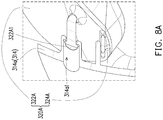
- FIG. 8A is a schematic partial cross-sectional view of the head-mounted display device of FIG. 7A .
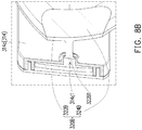
- FIG. 8B is a schematic partial cross-sectional view the head-mounted display device of FIG. 7B .
- the head-mounted display device 300 includes a wearable assembly 310, a first cushion 320A, a second cushion 320B and at least one adjustable fixing assembly.
- implementation of the at least one adjustable fixing assembly is the same to that of the first adjustable fixing assembly 130A and the second adjustable fixing assembly 130B of the head-mounted display device 100, and detail thereof is not repeated.
- the wearable assembly 310 includes a main body 312 and a headband assembly 314 connected to the main body 312.
- the headband assembly 314 includes an eye contact portion 314a capable of covering the two eyes of the user, a pair of extension portions 314b respectively connected to two opposite ends of the eye contact portion 314a, and a rotation mechanism 314c coupled to the pair of extension portions 314b.
- the rotation mechanism 314c is adapted to rotate and drive the pair of extension portions 314b to tighten or loosen, so as to increase or decrease a total length of the pair of extension portions 314b.
- the eye contact portion 214a has a pair of first sliding channels 314a1.
- the first cushion 320A includes a first support portion 322A and a first buffer portion 324A connected to the first support portion 322A.
- the first support portion 322A includes a pair of first sliding portions 322A1 corresponding to the pair of first sliding channels 314a1, and the pair of first sliding portions 322A1 are movably disposed in the pair of first sliding channels 314a1.
- the first buffer portion 324A is configured to contact the frontal bone of the user.
- the rotation mechanism 314c has a pair of second sliding channels 314c1.
- the second cushion 320B includes a second support portion 322B and a second buffer portion 324B connected to the second support portion 322B.
- the second support portion 322B includes a pair of second sliding portions 322B1 corresponding to the pair of second sliding channels 314c1, and the pair of second sliding portions 322B1 are movably disposed in the pair of second sliding channels 314c1, and the second sliding portions 322B1 are, for example, columnar structures, but not limited thereto.
- the second buffer portion 324B is configured to contact the occipital bone of the user.
- the wearable assembly is adapted to be worn on the head of the user, the cushions are floatingly connected to the wearable assembly, and when the first positioning structure and the second positioning structure are structurally interfered to position the cushions to the wearable assembly, the upper sides and the lower sides of the cushions may contact the head of the user at the same time, so that the cushions may be matched to the head shapes of the users, which avails the user more stably wearing the head-mounted display device on the head, and improving comfort of the user wearing the head-mounted display device.
Landscapes
- Physics & Mathematics (AREA)
- General Physics & Mathematics (AREA)
- Optics & Photonics (AREA)
- Engineering & Computer Science (AREA)
- Computer Hardware Design (AREA)
- Theoretical Computer Science (AREA)
- Human Computer Interaction (AREA)
- General Engineering & Computer Science (AREA)
Abstract
Description
- This application claims the priority benefit of
U.S. provisional application serial no. 62/666,098, filed on May 3, 2018 - The application relates to a head-mounted display device, and particularly relates to a head-mounted display device capable of improving wearing comfort.
- Along with quick development of science and technology industry, types, functions, and usage of display devices are becoming more diverse, and wearable display devices that may be directly attached to the user's body are also developed. There are quite a lot of types of head-mounted display devices, and taking an eyemask type head-mounted display device as an example, after a user wears such type of the display device, besides that the user may view three-dimensional images, the images may be changed along with turning of user's head, which provides the user with a more immersive experience.
- However, some users may feel uncomfortable after wearing most of the head-mounted display devices on the market, because most of the head-mounted display devices on the market have headband and cushion designs that are not suitable for head shapes of these users. Therefore, how to make the head-mounted display device more stably worn on the user's head while also providing a more comfortable use experience to the user is a very important subject in the field.
- The application is directed to a head-mounted display device, which is capable of matching with head shapes of different users, such that the users can more stably wear the head-mounted display device to improve wearing comfort of the user.
- The application provides a head-mounted display device including a wearable assembly, at least one cushion and at least one adjustable fixing assembly. The wearable assembly is adapted to be worn on a head of a user. The at least one cushion is adapted to contact the head of the user, and is floatingly connected to the wearable assembly. The at least one adjustable fixing assembly includes a first positioning structure and a second positioning structure. The first positioning structure is connected to the wearable assembly, and the second positioning structure is connected to the at least one cushion. A structural interference generated between the first positioning structure and the second positioning structure positions the at least one cushion to the wearable assembly.
- Based on the above description, in the head-mounted display device of the application, the wearable assembly is adapted to be worn on the head of the user, the at least one cushion is floatingly connected to the wearable assembly, and is adapted to contact the head of the user when the wearable assembly is worn on the head of the user. The structural interference generated between the first positioning structure and the second positioning structure positions the at least one cushion to the wearable assembly. In this way, the head-mounted display device may be matched to head shapes of different users, such that the users may more stably wear the head-mounted display devices to improve wearing comfort of the user wearing the head-mounted display device.
- To make the aforementioned more comprehensible, several embodiments accompanied with drawings are described in detail as follows.
-
-
FIG. 1A is a schematic three-dimensional view of a head-mounted display device according to an embodiment of the application. -
FIG. 1B is a schematic three-dimensional view of the head-mounted display device ofFIG. 1A viewing from another viewing angle. -
FIG. 2A is a schematic partial cross-sectional view of the head-mounted display device ofFIG. 1A . -
FIG. 2B is a schematic partial cross-sectional view of the head-mounted display device ofFIG. 1B . -
FIG. 3A is a schematic cross-sectional view of cushions of the head-mounted display device ofFIG. 1A before being subjected to external forces. -
FIG. 3B is a schematic diagram of the cushions of the head-mounted display device ofFIG. 3A positioned to a wearable assembly after being subjected to the external forces. -
FIG. 4A is a schematic cross-sectional view of the cushions of the head-mounted display device ofFIG. 1A rotated relative to the wearable assembly after being subjected to the external force. -
FIG. 4B is a schematic cross-sectional view of the cushions of the head-mounted display device ofFIG. 4A positioned to the wearable assembly after being subjected to the external force. -
FIG. 5 is a schematic three-dimensional view of a head-mounted display device according to another embodiment of the application. -
FIG. 6A is a schematic cross-sectional view of cushions of the head-mounted display device ofFIG. 5 being not subjected to external forces. -
FIG. 6B is a schematic diagram of the cushions of the head-mounted display device ofFIG. 6A positioned to the wearable assembly after being subjected to the external forces. -
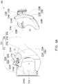
FIG. 7A is a schematic three-dimensional view of a head-mounted display device according to another embodiment of the application. -
FIG. 7B is a schematic three-dimensional view of the head-mounted display device ofFIG. 7A in another viewing angle. -
FIG. 8A is a schematic partial cross-sectional view of the head-mounted display device ofFIG. 7A . -
FIG. 8B is a schematic partial cross-sectional view the head-mounted display device ofFIG. 7B . -
FIG. 1A is a schematic three-dimensional view of a head-mounted display device according to an embodiment of the application.FIG. 1B is a schematic three-dimensional view of the head-mounted display device ofFIG. 1A viewing from another viewing angle. Referring toFIG. 1A andFIG. 1B , the head-mounteddisplay device 100 includes awearable assembly 110, at least one cushion and an adjustable fixing assembly. The at least one cushion (for example, afirst cushion 120A and asecond cushion 120B ofFIG. 3A ) is floatingly connected to thewearable assembly 110. Thewearable assembly 110 may be worn on a head of a user, and the at least one cushion is adapted to contact the head of the user when thewearable assembly 110 is worn on the head of the user, and the at least one cushion may be positioned to thewearable assembly 110 through the at least one adjustable fixing assembly (for example, a firstadjustable fixing assembly 130A and a second adjustable fixingassembly 130B shown inFIG. 3A ). In this way, the head-mounteddisplay device 100 may be matched to head shapes of different users, such that the users may more stably wear the head-mounteddisplay device 100 to improve wearing comfort of the user wearing the head-mounteddisplay device 100. -
FIG. 3A is a schematic cross-sectional view of the cushions of the head-mounted display device ofFIG. 1A before being subjected to external forces. For clarity of representation and convenience of description, first sliding channels 114a1, second sliding channels 114c1, first sliding portions 122A1 and second sliding portions 122B1 are shown by dashed lines inFIG. 3A . Referring toFIG. 1A ,FIG. 1B andFIG. 3A , in detail, thewearable assembly 110 includes amain body 112 and aheadband assembly 114 connected to themain body 112. Adisplay 112a may be built in or additionally configured to themain body 112. Thedisplay 112a may project display images to the eyes of the user when the user wears theheadband assembly 114. In detail, theheadband assembly 114 includes aneye contact portion 114a, a pair ofextension portions 114b respectively connected to two opposite ends of theeye contact portion 114a, and arotation mechanism 114c coupled to the pair ofextension portions 114b. When the user wants to wear thewearable assembly 110 on the head, the user may cover theeye contact portion 114a on the two eyes of the user, and rotates therotation mechanism 114c to drive the pair ofextension portions 114b to tighten or loosen, so as to adjust a total length of the pair ofextension portions 114b, and thus thewearable assembly 110 is adapted to be worn on the head of the user. -
FIG. 2A is a schematic partial cross-sectional view of the head-mounted display device ofFIG. 1A .FIG. 2B is a schematic partial cross-sectional view of the head-mounted display device ofFIG. 1B . Referring toFIG. 1A ,FIG. 2A andFIG. 3A , the at least one cushion may include thefirst cushion 120A and thesecond cushion 120B. Thefirst cushion 120A includes afirst support portion 122A made of a rigid material, and afirst buffer portion 124A made of a soft material, thefirst support portion 122A is used for supporting, and thefirst buffer portion 124A may contact the head of the user to improve comfort of the user wearing the head-mounteddisplay device 100. Thefirst support portion 122A includes a pair of first sliding portions 122A1, and the pair of the first sliding portions 122A1 are respectively connected to two opposite ends of thefirst support portion 122A. On the other hand, theeye contact portion 114a has a pair of first sliding channels 114a1 corresponding to the pair of first sliding portions 122A1, and the pair of first sliding portions 122A1 are movably disposed in the pair of first sliding channels 114a1, such that thefirst cushion 120A is floatingly connected to thewearable assembly 110. - Referring to
FIG. 1B ,FIG. 2B andFIG. 3A , similarly, thesecond cushion 120B includes asecond support portion 122B made of the rigid material, and a second buffer portion 124BA made of the soft material, thesecond support portion 122B is used for supporting, and thesecond buffer portion 124B may contact the head of the user to improve comfort of the user wearing the head-mounteddisplay device 100. Thesecond support portion 122B includes a pair of second sliding portions 122B1, and the pair of the second sliding portions 122B1 are respectively connected to two opposite ends of thesecond support portion 122B. On the other hand, therotation mechanism 114c has a pair of second sliding channels 114c1 corresponding to the pair of second sliding portions 122B1, and the pair of second sliding portions 122B1 are movably disposed in the pair of second sliding channels 114c1, such that thesecond cushion 120B is floatingly connected to thewearable assembly 110. - In the embodiment, the first sliding portions 122A1 and the second sliding portions 122B1 are, for example, spherical structures, though in other embodiments, the first sliding portions and the second sliding portions may also be columnar structures, which is not limited here, as long as the first sliding portions 122A1 may be slid and rotated in the first sliding channel 114a1, and the second sliding portions 122B1 may be slid and rotated in the second sliding channel 114c1.
- Moreover, the number of the cushions may be increased or decreased according to an actual requirement, and the sliding portions and the sliding channels may also be increased or decreased according to the number of the cushions. On the other hand, the cushions may be disposed at any place of the
wearable assembly 110 according to an actual requirement, for example, at least one pair of the sliding channels may be disposed on theeye contact portion 114a, theextension portion 114b or therotation mechanism 114c, such that the cushions are floatingly connected to theeye contact portion 114a, theextension portion 114b or therotation mechanism 114c through coordination between the sliding portions and the sliding channels, so as to contact different positions of the user's head. In brief, thewearable assembly 110 may have at least one pair of sliding channels, at least one cushion and at least one pair of sliding portions corresponding to the at least one pair of sliding channels, the pair of sliding portions are located at two opposite ends of the at least one cushion, and the pair of sliding portions are movably disposed in the pair of sliding channels, such that the at least one cushion is floatingly connected to thewearable assembly 110. - Referring to
FIG. 1A ,FIG. 1B andFIG. 3A , the at least one adjustable fixing assembly may include a firstadjustable fixing assembly 130A and a second adjustable fixingassembly 130B. The firstadjustable fixing assembly 130A includes a first positioning structure (for example, afirst interference portion 132A inFIG. 3A ) and a second positioning structure (for example, asecond interference portion 134A inFIG. 3A ), the first positioning structure is connected to theeye contact portion 114a, and the second positioning structure is connected to thefirst cushion 120A. The second adjustable fixingassembly 130B includes a third positioning structure (for example, athird interference portion 132B inFIG. 3A ) and a fourth positioning structure (for example, afourth interference portion 134B inFIG. 3A ), the third positioning structure is connected to therotation mechanism 114c, and the fourth positioning structure is connected to thesecond cushion 120B. -
FIG. 3B is a schematic diagram of the cushions of the head-mounted display device ofFIG. 3A positioned to the wearable assembly after being subjected to the external forces. For clarity of representation and convenience of description, the first sliding channels 114a1, the second sliding channels 114c1, the first sliding portions 122A1 and the second sliding portions 122B1 are shown by dashed lines inFIG. 3B . Referring toFIG. 3A andFIG. 3B , thefirst buffer portion 124A of thefirst cushion 120A has a first upper side 124A1 and a first lower side 124A2 opposite to each other. Thesecond buffer portion 124B of thesecond cushion 120B has a second lower side 124B1 and a second upper side 124B2 opposite to each other.FIG. 3A illustrates a state that thefirst cushion 120A is not subjected to a first external force F1, and thesecond cushion 120B is not subjected to a second external force F2. When the user wears theheadband assembly 114 on the head, the first upper side 124A1 of thefirst cushion 120A may contact a frontal bone of the user, and the second lower side 124B1 of thesecond cushion 120B may contact an occipital bone of the user. - Thereafter, the user may rotate the
rotation mechanism 114c to drive the pair ofextension portions 114b to tighten, such that a total length of the pair ofextension portions 114b is shortened, and thefirst cushion 120A is accordingly subjected to the first external force F1, and thesecond cushion 120B is subjected to the second external force F2. - On the other hand, the first positioning structure includes a
first interference portion 132A, and the second positioning structure includes a plurality ofsecond interference portions 134A corresponding to thefirst interference portion 132A. The third positioning structure includes athird interference portion 132B, and the fourth positioning structure includes a plurality offourth interference portions 134B corresponding to thethird interference portion 132B. - Referring to
FIG. 3A andFIG. 3B, FIG. 3B illustrates thefirst cushion 120A ofFIG. 3A subjected to the first external force F1 is only translated towards theeye contact portion 114a without being rotated, and thesecond cushion 120B subjected to the second external force F2 is only translated towards therotation mechanism 114c without being rotated. When thefirst cushion 120A is subjected to the first external force F1 to drive the second positioning structure to move towards the first positioning structure relative to theeye contact portion 114a and the two opposite ends of thefirst cushion 120A are translated towards each other under the function of the first external force F1 to make thefirst interference portion 132A to be moved between two adjacentsecond interference portions 134A to engage with the two adjacentsecond interference portions 134A, the mutual engagement between the first positioning structure and the second positioning structure positions thefirst cushion 120A to thewearable assembly 110. When the first positioning structure and the second positioning structure are structurally interfered to position thefirst cushion 120A to theeye contact portion 114a, the first upper side 124A1 and the first lower side 124A2 of thefirst cushion 120A contact the frontal bone of the user at the same time, so that thefirst cushion 120A is matched with a head shape of the user, which avails the user more stably wearing the head-mounteddisplay device 100 on the head, and improving comfort of the user wearing the head-mounteddisplay device 100. - Similarly, when the
second cushion 120B is subjected to the second external force F2 to drive the fourth positioning structure to move towards the third positioning structure relative to therotation mechanism 114c and the two opposite ends of thesecond cushion 120B are translated towards each other under the function of the second external force F2 to make thethird interference portion 132B to be moved between two adjacentfourth interference portions 134B to engage with one of the two adjacentfourth interference portions 134B, the mutual engagement between the third positioning structure and the fourth positioning structure positions thesecond cushion 120B to thewearable assembly 110. When the third positioning structure and the fourth positioning structure are structurally interfered to position thesecond cushion 120B to therotation mechanism 114c, the second lower side 124B1 and the second upper side 124B2 of thesecond cushion 120B contact the occipital bone of the user at the same time, so that thesecond cushion 120B is matched with a head shape of the user, which avails the user more stably wearing the head-mounteddisplay device 100 on the head, and improving comfort of the user wearing the head-mounteddisplay device 100. -
FIG. 4A is a schematic cross-sectional view of the cushions of the head-mounted display device ofFIG. 1A rotated relative to the wearable assembly after being subjected to the external force.FIG. 4B is a schematic cross-sectional view of the cushions of the head-mounted display device ofFIG. 4A positioned to the wearable assembly after being subjected to the external force. For clarity of representation and convenience of description, the first sliding channels 114a1, the second sliding channels 114c1, the first sliding portions 122A1 and the second sliding portions 122B1 are shown by dashed lines inFIG. 4A andFIG. 4B . Referring toFIG. 4A andFIG. 4B ,FIG. 4A illustrates a schematic diagram that thefirst cushion 120A ofFIG. 3A subjected to the first external force F1 is translated towards theeye contact portion 114a and is rotated, and thesecond cushion 120B subjected to the second external force F2 is translated towards therotation mechanism 114c and is rotated. When thefirst cushion 120A is subjected to the first external force F1 to drive the second positioning structure to move towards the first positioning structure relative to theeye contact portion 114a and the two opposite ends of thefirst cushion 120A are translated towards each other under the function of the first external force F1, and thefirst cushion 120A is rotated relative to theeye contact portion 114a to make thefirst interference portion 132A to be moved between two adjacentsecond interference portions 134A to engage with the two adjacentsecond interference portions 134A, the mutual engagement between the first positioning structure and the second positioning structure positions thefirst cushion 120A to thewearable assembly 110. When the first positioning structure and the second positioning structure are structurally interfered to position thefirst cushion 120A to theeye contact portion 114a, the first upper side 124A1 and the first lower side 124A2 of thefirst cushion 120A contact the frontal bone of the user at the same time. In other words, when the head-mounteddisplay device 100 is worn on a head of a user with a different head shape, thefirst cushion 120A may be rotated by a different angle relative to theeye contact portion 114a in response to the head shapes of different users, so that the head-mounteddisplay device 100 may be matched with head shapes of different users, which avails the user more stably wearing the head-mounteddisplay device 100 on the head, and improving comfort of the user wearing the head-mounteddisplay device 100. - Similarly, when the
second cushion 120B is subjected to the second external force F2 to drive the fourth positioning structure to move towards the third positioning structure relative to therotation mechanism 114c and the two opposite ends of thesecond cushion 120B are translated towards each other under the function of the second external force F2, and thesecond cushion 120B is rotated relative to therotation mechanism 114c to make thethird interference portion 132B to be moved between two adjacentfourth interference portions 134B to engage with one of the two adjacentfourth interference portions 134B, the mutual engagement between the third positioning structure and the fourth positioning structure positions thesecond cushion 120B to thewearable assembly 110. When the third positioning structure and the fourth positioning structure are structurally interfered to position thesecond cushion 120B to therotation mechanism 114c, the second lower side 124B1 and the second upper side 124B2 of thesecond cushion 120B contact the occipital bone of the user at the same time. In other word, when the head-mounteddisplay device 100 is worn on a head of a user with a different head shape, thesecond cushion 120B may be rotated by a different angle relative to therotation mechanism 114c in response to the head shapes of different users, so that the head-mounteddisplay device 100 may be matched with head shapes of different users, which avails the head-mounteddisplay device 100 can be more stably worn on the heads of different users, and improving comfort of the user wearing the head-mounteddisplay device 100. - In the embodiment, the number and configuration positions of the cushions may be adjusted according to an actual requirement. For example, the head-mounted
display device 100 may be only configured with a singlefirst cushion 120A or a singlesecond cushion 120B, or configured with both of thefirst cushion 120A and thesecond cushion 120B. In other embodiments, the cushions may be configured on at least one of theeye contact portion 114a, theextension portion 114b and therotation mechanism 114c to contact different parts of the user's head. - Moreover, the
first support portion 122A, the first sliding portion 122A1 and thesecond interference portion 134A of the second positioning structure are, for example, formed integrally, but may also be assembled from different members in other embodiments. Similarly, thesecond support portion 122B, the second sliding portion 122B1 and thefourth interference portion 134B of the fourth positioning structure are, for example, formed integrally, but may also be assembled from different members in other embodiments. - On the other hand, referring to
FIG. 1A , theeye contact portion 114a includes a first position limiting portion 114a2, thefirst support portion 122A of thefirst cushion 120A includes a second position limiting portion 122A2 corresponding to the first position limiting portion 114a2, and the first position limiting portion 114a2 and the second position limiting portion 122A2 are configured to limit rotation of thefirst cushion 120A relative to theeye contact portion 114a. Moreover, structures the same as the first position limiting portion 114a2 and the second position limiting portion 122A2 may also be configured between thesecond cushion 120B and therotation mechanism 114c to limit rotation of thesecond cushion 120B relative to therotation mechanism 114c, and details thereof are not repeated. -
FIG. 5 is a schematic three-dimensional view of a head-mounted display device according to another embodiment of the application.FIG. 6A is a schematic cross-sectional view of cushions of the head-mounted display device ofFIG. 5 being not subjected to external forces.FIG. 6B is a schematic diagram of the cushions of the head-mounted display device ofFIG. 6A positioned to the wearable assembly after being subjected to the external forces. For clarity of representation and convenience of description, the first sliding channels 214a1, the second sliding channels 214c1, the first sliding portions 222A1 and the second sliding portions 222B1 are shown by dashed lines inFIG. 6A andFIG. 6B . Referring toFIG. 5 ,FIG. 6A andFIG. 6B , the head-mounteddisplay device 200 includes awearable assembly 210, afirst cushion 220A, asecond cushion 220B, a firstadjustable fixing assembly 230A and a second adjustable fixingassembly 230B. - In detail, the
wearable assembly 210 includes amain body 212 and aheadband assembly 214 connected to themain body 212. Theheadband assembly 214 includes aneye contact portion 214a capable of covering the two eyes of the user, a pair ofextension portions 214b respectively connected to two opposite ends of theeye contact portion 214a, and arotation mechanism 214c coupled to the pair ofextension portions 214b, and therotation mechanism 214c is adapted to rotate and drive the pair ofextension portions 214b to tighten or loosen, so as to increase or decrease a total length of the pair ofextension portions 214b. Adisplay 212a may be built in or additionally assembled in themain body 212, and thedisplay 212a may project display images to the eyes of the user. - On the other hand, the
eye contact portion 214a has a pair of first sliding channels 214a1. Thefirst cushion 220A includes afirst support portion 222A and afirst buffer portion 224A connected to thefirst support portion 222A. Thefirst support portion 222A includes a pair of first sliding portions 222A1 corresponding to the pair of first sliding channels 214a1, the pair of first sliding portions 222A1 are movably disposed in the pair of first sliding channels 214a1, and the first sliding portions 222A1 are, for example, spherical structures, but not limited thereto. Thefirst buffer portion 224A is configured to contact the frontal bone of the user, and has a first upper side 224A1 and a first lower side 224A2 opposite to each other. - The
rotation mechanism 214c has a pair of second sliding channels 214c1. Thesecond cushion 220B includes asecond support portion 222B and asecond buffer portion 224B connected to thesecond support portion 222B. Thesecond support portion 222B includes a pair of second sliding portions 222B1 corresponding to the pair of second sliding channels 214c1, the pair of second sliding portions 222B1 are movably disposed in the pair of second sliding channels 214c1, and the second sliding portions 222B1 are, for example, spherical structures, but not limited thereto. Thesecond buffer portion 224B is configured to contact the occipital bone of the user, and has a second lower side 224B1 and a second upper side 224B2 opposite to each other. - When the
headband assembly 214 is worn on the head of the user, the first upper side 224A1 of thefirst buffer portion 224A contacts the frontal bone of the user, and the second lower side 224B1 of thesecond buffer portion 224B contacts the occipital bone of the user. - In the embodiment, the first
adjustable fixing assembly 230A includes a first positioning structure (for example, arough surface 232A inFIG. 6A ) and a second positioning structure (for example, anotherrough surface 234A inFIG. 6A ), the first positioning structure is connected to theeye contact portion 214a of theheadband assembly 214, and the second positioning structure is connected to thefirst support portion 222A of thefirst cushion 220A. The first positioning structure includes arough surface 232A, and the second positioning structure includes anotherrough surface 234A corresponding to the first positioning structure. - The second adjustable fixing
assembly 230B includes a third positioning structure (for example, arough surface 232B inFIG. 6A ) and a fourth positioning structure (for example, anotherrough surface 234B inFIG. 6A ), the third positioning structure is connected to therotation mechanism 214c of theheadband assembly 214, and the fourth positioning structure is connected to thesecond support portion 222B of thesecond cushion 220B. The third positioning structure includes arough surface 232B, and the fourth positioning structure includes anotherrough surface 234B corresponding to the third positioning structure. - When the
first cushion 220A is subjected to the first external force F1 to drive the second positioning structure to move towards the first positioning structure relative to theeye contact portion 214a of thewearable assembly 210 and rotate relative to theeye contact portion 214a of thewearable assembly 210 to make the otherrough surface 234A to contact therough surface 232A, friction generated between the first positioning structure and the second positioning structure positions thefirst cushion 220A to theeye contact portion 214a of thewearable assembly 210, and the first upper side 224A1 and the first lower side 224A2 of thefirst cushion 220A contact the frontal bone of the user at the same time. When thesecond cushion 220B is subjected to the second external force F2 to drive the fourth positioning structure to move towards the third positioning structure relative to therotation mechanism 214c of thewearable assembly 210 and rotate relative to therotation mechanism 214c of thewearable assembly 210 to make the otherrough surface 234B to contact therough surface 232B, friction generated between the third positioning structure and the fourth positioning structure positions thesecond cushion 220B to therotation mechanism 214c of thewearable assembly 210, and the first lower side 224B1 and the second upper side 224B2 of thesecond cushion 220B contact the occipital bone of the user at the same time. In this way, the head-mounteddisplay device 200 may be matched with different head shapes of the users, which avails the user more stably wearing the head-mounteddisplay device 200 on the head, and improving comfort of the user wearing the head-mounteddisplay device 200. -
FIG. 7A is a schematic three-dimensional view of a head-mounted display device according to another embodiment of the application.FIG. 7B is a schematic three-dimensional view of the head-mounted display device ofFIG. 7A in another viewing angle.FIG. 8A is a schematic partial cross-sectional view of the head-mounted display device ofFIG. 7A .FIG. 8B is a schematic partial cross-sectional view the head-mounted display device ofFIG. 7B . Referring toFIG. 7A to FIG. 8B , the head-mounteddisplay device 300 includes awearable assembly 310, afirst cushion 320A, asecond cushion 320B and at least one adjustable fixing assembly. In the head-mounteddisplay device 300 of the embodiment, implementation of the at least one adjustable fixing assembly is the same to that of the firstadjustable fixing assembly 130A and the second adjustable fixingassembly 130B of the head-mounteddisplay device 100, and detail thereof is not repeated. - In detail, the
wearable assembly 310 includes amain body 312 and aheadband assembly 314 connected to themain body 312. Theheadband assembly 314 includes aneye contact portion 314a capable of covering the two eyes of the user, a pair ofextension portions 314b respectively connected to two opposite ends of theeye contact portion 314a, and arotation mechanism 314c coupled to the pair ofextension portions 314b. Therotation mechanism 314c is adapted to rotate and drive the pair ofextension portions 314b to tighten or loosen, so as to increase or decrease a total length of the pair ofextension portions 314b. - On the other hand, the
eye contact portion 214a has a pair of first sliding channels 314a1. Thefirst cushion 320A includes afirst support portion 322A and afirst buffer portion 324A connected to thefirst support portion 322A. Thefirst support portion 322A includes a pair of first sliding portions 322A1 corresponding to the pair of first sliding channels 314a1, and the pair of first sliding portions 322A1 are movably disposed in the pair of first sliding channels 314a1. Thefirst buffer portion 324A is configured to contact the frontal bone of the user. - The
rotation mechanism 314c has a pair of second sliding channels 314c1. Thesecond cushion 320B includes asecond support portion 322B and asecond buffer portion 324B connected to thesecond support portion 322B. Thesecond support portion 322B includes a pair of second sliding portions 322B1 corresponding to the pair of second sliding channels 314c1, and the pair of second sliding portions 322B1 are movably disposed in the pair of second sliding channels 314c1, and the second sliding portions 322B1 are, for example, columnar structures, but not limited thereto. Thesecond buffer portion 324B is configured to contact the occipital bone of the user. - In summary, in the head-mounted display device of the application, the wearable assembly is adapted to be worn on the head of the user, the cushions are floatingly connected to the wearable assembly, and when the first positioning structure and the second positioning structure are structurally interfered to position the cushions to the wearable assembly, the upper sides and the lower sides of the cushions may contact the head of the user at the same time, so that the cushions may be matched to the head shapes of the users, which avails the user more stably wearing the head-mounted display device on the head, and improving comfort of the user wearing the head-mounted display device.
- Although the application has been disclosed by the above embodiments, they are not intended to limit the application. It is apparent to one of ordinary skill in the art that modifications and variations to the application may be made without departing from the spirit and scope of the application. Accordingly, the protection scope of the application will be defined by the appended claims.
Claims (15)
- A head-mounted display device, comprising:a wearable assembly, adapted to be worn on a head of a user;at least one cushion, adapted to contact the head of the user, and floatingly connected to the wearable assembly; andat least one adjustable fixing assembly, comprising a first positioning structure and a second positioning structure,wherein the first positioning structure is connected to the wearable assembly, the second positioning structure is connected to the at least one cushion, and a structural interference generated between the first positioning structure and the second positioning structure positions the at least one cushion to the wearable assembly.
- The head-mounted display device as claimed in claim 1, wherein the at least one cushion is subjected to an external force to drive the second positioning structure to move towards the first positioning structure relative to the wearable assembly, and when the second positioning structure and the first positioning structure generate a structural interference, the structural interference generated between the first positioning structure and the second positioning structure positions the at least one cushion to the wearable assembly.
- The head-mounted display device as claimed in claim 2, wherein the at least one cushion is subjected to the external force to drive the second positioning structure to move towards the first positioning structure relative to the wearable assembly, and two opposite ends of the at least one cushion are adapted to translate towards each other under the external force, and the at least one cushion is adapted to drive the second positioning structure to rotate relative to the wearable assembly under the external force.
- The head-mounted display device as claimed in claim 2, wherein the first positioning structure comprises a first interference portion, the second positioning structure comprises a plurality of second interference portions, and when the at least one cushion is subjected to the external force to drive the second positioning structure to move relative to the wearable assembly and rotate relative to the wearable assembly, and the first interference portion is moved between two adjacent second interference portions to make the second positioning structure to engage with the first positioning structure, the mutual engagement between the first positioning structure and the second positioning structure positions the at least one cushion to the wearable assembly.
- The head-mounted display device as claimed in claim 2, wherein the first positioning structure comprises a rough surface, the second positioning structure comprises another rough surface corresponding to the first positioning structure, and when the at least one cushion is subjected to the external force to drive the second positioning structure to move towards the first positioning structure relative to the wearable assembly and rotate relative to the wearable assembly to make the second positioning structure and the first positioning structure to contact each other, friction generated between the first positioning structure and the second positioning structure positions the at least one cushion to the wearable assembly.
- The head-mounted display device as claimed in claim 1, wherein the wearable assembly has at least one pair of sliding channels, the at least one cushion has at least one pair of sliding portions corresponding to the at least one pair of sliding channels, the pair of sliding portions are located at two opposite ends of the at least one cushion, and the pair of sliding portions are respectively movably disposed in the pair of sliding channels.
- The head-mounted display device as claimed in claim 6, wherein the pair of sliding portions are spherical structures.
- The head-mounted display device as claimed in claim 1, wherein the wearable assembly comprises:a main body, adapted to project display images towards two eyes of the user; anda headband assembly, connected to the main body, and adapted to be worn on the head of the user, wherein the headband assembly comprises:an eye contact portion, adapted to cover the two eyes of the user;a pair of extension portions, respectively connected to two opposite ends of the eye contact portion; anda rotation mechanism, coupled to the pair of extension portions, and adapted to rotate to drive the pair of extension portions to tighten or loosen, so as to adjust a total length of the pair of extension portions.
- The head-mounted display device as claimed in claim 8, wherein the eye contact portion has a pair of sliding channels, the cushion has a pair of sliding portions corresponding to the pair of sliding channels, the pair of sliding portions are located at two opposite ends of the cushion, and the pair of sliding portions are respectively movably disposed in the pair of sliding channels.
- The head-mounted display device as claimed in claim 9, wherein the cushion is adapted to contact a frontal bone of the user, and has an upper side and a lower side opposite to each other, wherein when the headband assembly is worn on the head of the user, the upper side contacts the frontal bone of the user, and when the cushion is subjected to an external force to drive the second positioning structure to move towards the first positioning structure relative to the eye contact portion and rotate relative to the eye contact portion to make the first positioning structure and the second positioning structure to generate a structural interference to position the cushion to the eye contact portion, the upper side and the lower side contact the frontal bone of the user.
- The head-mounted display device as claimed in claim 8, wherein the rotation mechanism has a pair of sliding channels, the cushion has a pair of sliding portions corresponding to the pair of sliding channels, the pair of sliding portions are located at two opposite ends of the cushion, and the pair of sliding portions are respectively movably disposed in the pair of sliding channels.
- The head-mounted display device as claimed in claim 11, wherein the cushion is adapted to contact an occipital bone of the user, and has an upper side and a lower side opposite to each other, wherein when the headband assembly is worn on the head of the user, the lower side contacts the occipital bone of the user, and when the cushion is subjected to an external force to drive the second positioning structure to move towards the first positioning structure relative to the rotation mechanism and rotate relative to the rotation mechanism to make the first positioning structure and the second positioning structure to generate a structural interference to position the cushion to the rotation mechanism, the lower side and the upper side contact the occipital bone of the user.
- The head-mounted display device as claimed in claim 8, wherein the at least one cushion comprises a first cushion and a second cushion, the eye contact portion has a pair of first sliding channels, the rotation mechanism has a pair of second sliding channels, the first cushion has a pair of first sliding portions corresponding to the pair of first sliding channels, the pair of first sliding portions are located at two opposite ends of the first cushion, the second cushion has a pair of second sliding portions corresponding to the pair of second sliding channels, the pair of second sliding portions are located at two opposite ends of the second cushion, the pair of first sliding portions are respectively movably disposed in the pair of first sliding channels, and the pair of second sliding portions are respectively movably disposed in the pair of second sliding channels.
- The head-mounted display device as claimed in claim 13, wherein the at least one adjustable fixing assembly comprises a first adjustable fixing assembly and a second adjustable fixing assembly, the first adjustable fixing assembly comprises the first positioning structure and the second positioning structure, the first positioning structure is connected to the eye contact portion, the second positioning structure is connected to the first cushion, the second adjustable fixing assembly comprises the third positioning structure and the fourth positioning structure, the third positioning structure is connected to the rotation mechanism, and the fourth positioning structure is connected to the second cushion.
- The head-mounted display device as claimed in claim 14, wherein the first cushion is adapted to contact a frontal bone of the user, and has a first upper side and a first lower side opposite to each other, the second cushion is adapted to contact an occipital bone of the user, and has a second lower side and a second upper side opposite to each other, wherein when the headband assembly is worn on the head of the user, the first upper side contacts the frontal bone of the user, the second lower side contacts the occipital bone of the user, and when the first cushion is subjected to a first external force to drive the second positioning structure to move towards the first positioning structure relative to the eye contact portion and rotate relative to the eye contact portion to make the first positioning structure and the second positioning structure to generate a structural interference to position the first cushion to the eye contact portion, the first upper side and the first lower side contact the frontal bone of the user, and when the second cushion is subjected to a second external force to drive the fourth positioning structure to move towards the third positioning structure relative to the rotation mechanism and rotate relative to the rotation mechanism to make the third positioning structure and the fourth positioning structure to generate a structural interference to position the second cushion to the rotation mechanism, the second lower side and the second upper side contact the occipital bone of the user.
Applications Claiming Priority (2)
| Application Number | Priority Date | Filing Date | Title |
|---|---|---|---|
| US201862666098P | 2018-05-03 | 2018-05-03 | |
| US16/198,776 US10905186B2 (en) | 2018-05-03 | 2018-11-22 | Head-mounted display device |
Publications (2)
| Publication Number | Publication Date |
|---|---|
| EP3564732A1 true EP3564732A1 (en) | 2019-11-06 |
| EP3564732B1 EP3564732B1 (en) | 2020-11-04 |
Family
ID=65894872
Family Applications (1)
| Application Number | Title | Priority Date | Filing Date |
|---|---|---|---|
| EP19164103.4A Active EP3564732B1 (en) | 2018-05-03 | 2019-03-20 | Head-mounted display device |
Country Status (2)
| Country | Link |
|---|---|
| US (1) | US10905186B2 (en) |
| EP (1) | EP3564732B1 (en) |
Families Citing this family (31)
| Publication number | Priority date | Publication date | Assignee | Title |
|---|---|---|---|---|
| US10905186B2 (en) * | 2018-05-03 | 2021-02-02 | Htc Corporation | Head-mounted display device |
| USD931277S1 (en) * | 2018-10-08 | 2021-09-21 | Microsoft Corporation | Headset with visor |
| US11163333B2 (en) * | 2019-03-29 | 2021-11-02 | Htc Corporation | Head-mounted display |
| USD917474S1 (en) | 2019-07-09 | 2021-04-27 | Htc Corporation | Display device |
| US11666112B2 (en) * | 2019-11-27 | 2023-06-06 | Final Forge, LLC | Headborne attachment platform including system, devices and methods |
| US11262589B2 (en) | 2020-03-27 | 2022-03-01 | ResMed Pty Ltd | Positioning and stabilising structure and system incorporating same |
| US12256057B2 (en) | 2019-12-31 | 2025-03-18 | ResMed Asia Pte. Ltd. | Positioning, stabilising, and interfacing structures and system incorporating same |
| USD925529S1 (en) | 2020-02-10 | 2021-07-20 | Facebook Technologies, Llc | Head-mounted display |
| US11686948B2 (en) | 2020-03-27 | 2023-06-27 | ResMed Pty Ltd | Positioning, stabilising, and interfacing structures and system incorporating same |
| US12178276B2 (en) | 2020-03-27 | 2024-12-31 | ResMed Pty Ltd | Positioning and stabilising structure and system incorporating same |
| US12564236B2 (en) | 2020-03-27 | 2026-03-03 | ResMed Pty Ltd | Positioning and stabilising structure and system incorporating same |
| US11598967B2 (en) | 2020-03-27 | 2023-03-07 | ResMed Pty Ltd | Positioning and stabilising structure and system incorporating same |
| US12554140B2 (en) | 2020-03-27 | 2026-02-17 | ResMed Pty Ltd | Positioning, stabilising, and interfacing structures and system incorporating same |
| DE102020002614A1 (en) * | 2020-04-30 | 2021-11-04 | Dräger Safety AG & Co. KGaA | Protective helmet with mechanical coding for plug connections between interior fittings and supporting structure |
| US11846390B2 (en) * | 2020-06-04 | 2023-12-19 | Meta Platforms Technologies, Llc | Pass-through ratcheting mechanism |
| US11982400B2 (en) * | 2020-08-04 | 2024-05-14 | Meta Platforms Technologies, Llc | Head cradle for head-mounted display and related systems and devices |
| US11726337B1 (en) | 2020-08-26 | 2023-08-15 | Apple Inc. | Systems with adjustable cushions |
| US11892647B2 (en) | 2020-09-28 | 2024-02-06 | Hewlett-Packard Development Company, L.P. | Head mountable device with tracking feature |
| USD972560S1 (en) * | 2020-10-08 | 2022-12-13 | Meta Platforms Technologies, Llc | Headset strap |
| USD968402S1 (en) | 2020-10-08 | 2022-11-01 | Meta Platforms Technologies, Llc | Headset strap |
| USD951250S1 (en) * | 2020-11-04 | 2022-05-10 | Htc Corporation | Display device |
| USD1000437S1 (en) * | 2021-05-03 | 2023-10-03 | Htc Corporation | Display device |
| TWM619525U (en) * | 2021-06-29 | 2021-11-11 | 廣達電腦股份有限公司 | Head-mounted display |
| USD997941S1 (en) * | 2021-07-08 | 2023-09-05 | Qingdao Pico Technology Co., Ltd. | Head-mounted display device |
| USD964988S1 (en) | 2021-10-18 | 2022-09-27 | Meta Platforms Technologies, Llc | Head-mounted display |
| JP1732921S (en) * | 2022-02-22 | 2022-12-22 | head mounted display | |
| JP1732920S (en) * | 2022-02-22 | 2022-12-22 | head mounted display | |
| CN116381941A (en) * | 2023-03-02 | 2023-07-04 | 维沃移动通信有限公司 | Wear-type wearing equipment |
| US12550964B2 (en) | 2023-04-27 | 2026-02-17 | Final Forge, LLC | Helmet having visor pivoting and locking mechanism and associated system and methods |
| US12638654B2 (en) | 2023-07-05 | 2026-05-26 | Apple Inc. | Electronic devices with adjustable eye relief |
| CN117741981A (en) * | 2023-12-22 | 2024-03-22 | 歌尔科技有限公司 | Anti-rotation fitting structure and head-mounted display device |
Citations (3)
| Publication number | Priority date | Publication date | Assignee | Title |
|---|---|---|---|---|
| JPH11119148A (en) * | 1997-10-15 | 1999-04-30 | Sony Corp | Optical vision device |
| US6388640B1 (en) * | 1998-01-09 | 2002-05-14 | Canon Kabushiki Kaisha | Head mount display |
| US20020118506A1 (en) * | 2001-02-28 | 2002-08-29 | Yoshihiro Saito | Mounting mechanism suitable for head mount display device and head mount display device using the same |
Family Cites Families (50)
| Publication number | Priority date | Publication date | Assignee | Title |
|---|---|---|---|---|
| US3787894A (en) * | 1972-10-12 | 1974-01-29 | J Goodman | Easily adjustable protective head gear |
| US6144347A (en) * | 1992-10-09 | 2000-11-07 | Sony Corporation | Head-mounted image display apparatus |
| DE69433821T2 (en) * | 1993-08-20 | 2005-06-16 | Seiko Epson Corp. | Head-mounted image display device |
| US6538624B1 (en) * | 1993-08-20 | 2003-03-25 | Seiko Epson Corporation | Head-mounted image display apparatus |
| EP0679919B1 (en) * | 1994-04-21 | 2000-07-12 | Sega Enterprises, Ltd. | Head mounted display |
| US5767820A (en) * | 1995-05-09 | 1998-06-16 | Virtual Research Systems | Head-mounted visual display apparatus |
| US5844656A (en) * | 1996-11-07 | 1998-12-01 | Xybernaut Corporation | Head mounted display with adjustment components |
| JP3880294B2 (en) | 2000-07-19 | 2007-02-14 | キヤノン株式会社 | Head mounting mechanism and head mounting device using the same |
| AT413641B (en) * | 2002-02-14 | 2006-04-15 | Life Optics Gmbh | HOLDER FOR EQUIPMENT TO BE CARRIED ON THE HEAD |
| JP4447999B2 (en) * | 2004-10-01 | 2010-04-07 | キヤノン株式会社 | Head mounting device and head mounting system |
| JP4402018B2 (en) * | 2005-07-04 | 2010-01-20 | キヤノン株式会社 | Head-mounted device |
| JP2007049684A (en) * | 2005-07-13 | 2007-02-22 | Canon Inc | Mounting mechanism and head-mounted image display device |
| JP4958599B2 (en) * | 2007-03-29 | 2012-06-20 | キヤノン株式会社 | Head-mounted video display device |
| US8370967B2 (en) * | 2009-10-21 | 2013-02-12 | Minson Enterprises Co., Ltd. | Adjustable head band for a helmet |
| JP2012186660A (en) * | 2011-03-06 | 2012-09-27 | Sony Corp | Head mounted display |
| JP5903018B2 (en) * | 2012-09-26 | 2016-04-13 | ソニー株式会社 | Head mounted display |
| JP5888205B2 (en) * | 2012-11-02 | 2016-03-16 | ソニー株式会社 | Image display device and information input device |
| US9703103B2 (en) * | 2014-03-14 | 2017-07-11 | Sony Corporation | Head-mounted display |
| JP6479156B2 (en) * | 2015-02-27 | 2019-03-06 | 株式会社ソニー・インタラクティブエンタテインメント | Head mounted display |
| JP6115585B2 (en) * | 2015-03-31 | 2017-04-19 | ブラザー工業株式会社 | Head mounted display and image display device |
| TWM515653U (en) | 2015-07-13 | 2016-01-11 | 銘異科技股份有限公司 | Head mounted display |
| CN204883055U (en) | 2015-07-23 | 2015-12-16 | 北京中创华影科技有限公司 | Head mounted display's forehead bearing structure |
| KR102568772B1 (en) * | 2015-09-25 | 2023-08-22 | 삼성전자주식회사 | Connection Device for Display device and Head-mounted Display Device |
| FR3043215B1 (en) * | 2015-10-30 | 2017-12-01 | Thales Sa | SYSTEM FOR VISUALIZING AND AUDIO COMMUNICATION GIVEN BY THE HEAD OF A USER COMPRISING A DEVICE FOR MAINTAINING RETRACTABLE NUQUE |
| KR20170062876A (en) * | 2015-11-30 | 2017-06-08 | 삼성전자주식회사 | Head-mounted display device with a detachable device |
| EP3196687B1 (en) * | 2016-01-20 | 2020-03-11 | Canon Kabushiki Kaisha | Head mounted device |
| US10152083B2 (en) * | 2016-02-26 | 2018-12-11 | Htc Corporation | Head mounted electronic device and head mounted electronic device cushion |
| US10502363B2 (en) * | 2016-05-17 | 2019-12-10 | Occipital, Inc. | Self-contained mixed reality head mounted display |
| US10684646B2 (en) * | 2016-08-02 | 2020-06-16 | Goertek Technology Co., Ltd. | Head-mounted resilient auxiliary locking mechanism and head-mounted display |
| CN106019602B (en) * | 2016-08-03 | 2018-03-30 | 深圳酷酷科技有限公司 | Head-mounted display apparatus |
| US10281728B2 (en) * | 2016-08-23 | 2019-05-07 | Facebook Technologies, Llc | Constant-force head mounted display restraint system |
| CN106154555B (en) * | 2016-08-24 | 2020-08-21 | 北京小米移动软件有限公司 | Virtual reality glasses |
| WO2018074657A1 (en) * | 2016-10-18 | 2018-04-26 | 엘지전자 주식회사 | Head-mounted display |
| WO2018124344A1 (en) * | 2016-12-29 | 2018-07-05 | 엘지전자 주식회사 | Wearable vr headband structure having automatic mechanism |
| EP3396436B1 (en) * | 2017-03-24 | 2020-10-07 | HTC Corporation | Head-mounted display device |
| CN206671689U (en) | 2017-04-27 | 2017-11-24 | 北京京东方光电科技有限公司 | Wearable device |
| US10848751B2 (en) * | 2017-05-19 | 2020-11-24 | Facebook Technologies, Llc | Interpupillary distance adjustment in a head-mounted display |
| WO2018221387A1 (en) * | 2017-05-31 | 2018-12-06 | 株式会社ソニー・インタラクティブエンタテインメント | Head-mounted display |
| KR102482756B1 (en) * | 2017-06-14 | 2022-12-30 | 삼성전자주식회사 | Head-mounted display apparatus |
| JP6646917B2 (en) * | 2017-06-21 | 2020-02-14 | 歌爾科技有限公司GoerTek Technology Co., Ltd. | Connection mechanism |
| US9989998B1 (en) * | 2017-07-18 | 2018-06-05 | Oculus Vr, Llc | Adjustable facial-interface systems for head-mounted displays |
| TWI626473B (en) * | 2017-07-25 | 2018-06-11 | 廣達電腦股份有限公司 | Head-mounted display |
| CN207123661U (en) | 2017-09-09 | 2018-03-20 | 深圳泰科晶显科技有限公司 | One kind is used for head mounted display |
| US11774768B2 (en) * | 2017-09-14 | 2023-10-03 | Apple Inc. | Face seal for head-mounted display |
| CN109752849B (en) * | 2017-11-03 | 2021-05-18 | 宏达国际电子股份有限公司 | head mounted display |
| CN109752848B (en) * | 2017-11-06 | 2021-08-17 | 宏达国际电子股份有限公司 | head mounted display |
| KR102579034B1 (en) * | 2018-02-23 | 2023-09-15 | 삼성전자주식회사 | An electronic device including a semi-transparent member disposed at an angle specified with respect to a direction in which a video is outputbelow the video outputmodule |
| US10905186B2 (en) * | 2018-05-03 | 2021-02-02 | Htc Corporation | Head-mounted display device |
| US11009712B2 (en) * | 2018-05-03 | 2021-05-18 | Htc Corporation | Head-mounted display device |
| JP7242241B2 (en) * | 2018-10-11 | 2023-03-20 | キヤノン株式会社 | head mounted device |
-
2018
- 2018-11-22 US US16/198,776 patent/US10905186B2/en active Active
-
2019
- 2019-03-20 EP EP19164103.4A patent/EP3564732B1/en active Active
Patent Citations (3)
| Publication number | Priority date | Publication date | Assignee | Title |
|---|---|---|---|---|
| JPH11119148A (en) * | 1997-10-15 | 1999-04-30 | Sony Corp | Optical vision device |
| US6388640B1 (en) * | 1998-01-09 | 2002-05-14 | Canon Kabushiki Kaisha | Head mount display |
| US20020118506A1 (en) * | 2001-02-28 | 2002-08-29 | Yoshihiro Saito | Mounting mechanism suitable for head mount display device and head mount display device using the same |
Also Published As
| Publication number | Publication date |
|---|---|
| US20190339736A1 (en) | 2019-11-07 |
| US10905186B2 (en) | 2021-02-02 |
| EP3564732B1 (en) | 2020-11-04 |
Similar Documents
| Publication | Publication Date | Title |
|---|---|---|
| EP3564732B1 (en) | Head-mounted display device | |
| TWI631371B (en) | Head-mounted display device | |
| US10660224B2 (en) | Head-mounted display device | |
| US11048298B2 (en) | Head-mounted display device | |
| US20170034611A1 (en) | Near-ear speaker device | |
| CN110873964B (en) | head mounted display | |
| CN110441907B (en) | Head-mounted display device | |
| US20200050235A1 (en) | Head-mounted display | |
| WO2011132485A1 (en) | Head-mounted video display device | |
| US20190238984A1 (en) | Headphone | |
| CN110865455B (en) | Nose pad structure and headgear using the same | |
| EP3407596A1 (en) | Head-mounted display | |
| JP7242241B2 (en) | head mounted device | |
| JP2005043701A (en) | Head mounted image display device | |
| JP7764473B2 (en) | Wearable video display device | |
| JP3215106U (en) | Non-contact type head mounted display | |
| EP3264157B1 (en) | Wearable electronic apparatus | |
| TWI748512B (en) | Head mounted display | |
| US12455459B2 (en) | Head-mounted device and headband | |
| CN111901717B (en) | Earphone module and head-mounted device | |
| CN217957286U (en) | Head earphone | |
| JP7498489B2 (en) | Eyewear | |
| CN121386192A (en) | Face engagement member for electronic device | |
| JP3855864B2 (en) | Head-mounted display device | |
| TWM488650U (en) | Eyeglasses with angle-adjustable nose pad |
Legal Events
| Date | Code | Title | Description |
|---|---|---|---|
| STAA | Information on the status of an ep patent application or granted ep patent |
Free format text: STATUS: EXAMINATION IS IN PROGRESS |
|
| PUAI | Public reference made under article 153(3) epc to a published international application that has entered the european phase |
Free format text: ORIGINAL CODE: 0009012 |
|
| 17P | Request for examination filed |
Effective date: 20190320 |
|
| AK | Designated contracting states |
Kind code of ref document: A1 Designated state(s): AL AT BE BG CH CY CZ DE DK EE ES FI FR GB GR HR HU IE IS IT LI LT LU LV MC MK MT NL NO PL PT RO RS SE SI SK SM TR |
|
| AX | Request for extension of the european patent |
Extension state: BA ME |
|
| RBV | Designated contracting states (corrected) |
Designated state(s): AL AT BE BG CH CY CZ DE DK EE ES FI FR GB GR HR HU IE IS IT LI LT LU LV MC MK MT NL NO PL PT RO RS SE SI SK SM TR |
|
| GRAP | Despatch of communication of intention to grant a patent |
Free format text: ORIGINAL CODE: EPIDOSNIGR1 |
|
| STAA | Information on the status of an ep patent application or granted ep patent |
Free format text: STATUS: GRANT OF PATENT IS INTENDED |
|
| INTG | Intention to grant announced |
Effective date: 20200703 |
|
| GRAS | Grant fee paid |
Free format text: ORIGINAL CODE: EPIDOSNIGR3 |
|
| GRAA | (expected) grant |
Free format text: ORIGINAL CODE: 0009210 |
|
| STAA | Information on the status of an ep patent application or granted ep patent |
Free format text: STATUS: THE PATENT HAS BEEN GRANTED |
|
| AK | Designated contracting states |
Kind code of ref document: B1 Designated state(s): AL AT BE BG CH CY CZ DE DK EE ES FI FR GB GR HR HU IE IS IT LI LT LU LV MC MK MT NL NO PL PT RO RS SE SI SK SM TR |
|
| REG | Reference to a national code |
Ref country code: GB Ref legal event code: FG4D |
|
| REG | Reference to a national code |
Ref country code: CH Ref legal event code: EP |
|
| REG | Reference to a national code |
Ref country code: AT Ref legal event code: REF Ref document number: 1331567 Country of ref document: AT Kind code of ref document: T Effective date: 20201115 |
|
| REG | Reference to a national code |
Ref country code: DE Ref legal event code: R096 Ref document number: 602019001159 Country of ref document: DE |
|
| REG | Reference to a national code |
Ref country code: IE Ref legal event code: FG4D |
|
| REG | Reference to a national code |
Ref country code: NL Ref legal event code: FP |
|
| REG | Reference to a national code |
Ref country code: AT Ref legal event code: MK05 Ref document number: 1331567 Country of ref document: AT Kind code of ref document: T Effective date: 20201104 |
|
| PG25 | Lapsed in a contracting state [announced via postgrant information from national office to epo] |
Ref country code: PT Free format text: LAPSE BECAUSE OF FAILURE TO SUBMIT A TRANSLATION OF THE DESCRIPTION OR TO PAY THE FEE WITHIN THE PRESCRIBED TIME-LIMIT Effective date: 20210304 Ref country code: RS Free format text: LAPSE BECAUSE OF FAILURE TO SUBMIT A TRANSLATION OF THE DESCRIPTION OR TO PAY THE FEE WITHIN THE PRESCRIBED TIME-LIMIT Effective date: 20201104 Ref country code: FI Free format text: LAPSE BECAUSE OF FAILURE TO SUBMIT A TRANSLATION OF THE DESCRIPTION OR TO PAY THE FEE WITHIN THE PRESCRIBED TIME-LIMIT Effective date: 20201104 Ref country code: NO Free format text: LAPSE BECAUSE OF FAILURE TO SUBMIT A TRANSLATION OF THE DESCRIPTION OR TO PAY THE FEE WITHIN THE PRESCRIBED TIME-LIMIT Effective date: 20210204 Ref country code: GR Free format text: LAPSE BECAUSE OF FAILURE TO SUBMIT A TRANSLATION OF THE DESCRIPTION OR TO PAY THE FEE WITHIN THE PRESCRIBED TIME-LIMIT Effective date: 20210205 |
|
| PG25 | Lapsed in a contracting state [announced via postgrant information from national office to epo] |
Ref country code: BG Free format text: LAPSE BECAUSE OF FAILURE TO SUBMIT A TRANSLATION OF THE DESCRIPTION OR TO PAY THE FEE WITHIN THE PRESCRIBED TIME-LIMIT Effective date: 20210204 Ref country code: SE Free format text: LAPSE BECAUSE OF FAILURE TO SUBMIT A TRANSLATION OF THE DESCRIPTION OR TO PAY THE FEE WITHIN THE PRESCRIBED TIME-LIMIT Effective date: 20201104 Ref country code: IS Free format text: LAPSE BECAUSE OF FAILURE TO SUBMIT A TRANSLATION OF THE DESCRIPTION OR TO PAY THE FEE WITHIN THE PRESCRIBED TIME-LIMIT Effective date: 20210304 Ref country code: LV Free format text: LAPSE BECAUSE OF FAILURE TO SUBMIT A TRANSLATION OF THE DESCRIPTION OR TO PAY THE FEE WITHIN THE PRESCRIBED TIME-LIMIT Effective date: 20201104 Ref country code: PL Free format text: LAPSE BECAUSE OF FAILURE TO SUBMIT A TRANSLATION OF THE DESCRIPTION OR TO PAY THE FEE WITHIN THE PRESCRIBED TIME-LIMIT Effective date: 20201104 Ref country code: ES Free format text: LAPSE BECAUSE OF FAILURE TO SUBMIT A TRANSLATION OF THE DESCRIPTION OR TO PAY THE FEE WITHIN THE PRESCRIBED TIME-LIMIT Effective date: 20201104 Ref country code: AT Free format text: LAPSE BECAUSE OF FAILURE TO SUBMIT A TRANSLATION OF THE DESCRIPTION OR TO PAY THE FEE WITHIN THE PRESCRIBED TIME-LIMIT Effective date: 20201104 |
|
| REG | Reference to a national code |
Ref country code: LT Ref legal event code: MG9D |
|
| PG25 | Lapsed in a contracting state [announced via postgrant information from national office to epo] |
Ref country code: HR Free format text: LAPSE BECAUSE OF FAILURE TO SUBMIT A TRANSLATION OF THE DESCRIPTION OR TO PAY THE FEE WITHIN THE PRESCRIBED TIME-LIMIT Effective date: 20201104 |
|
| PG25 | Lapsed in a contracting state [announced via postgrant information from national office to epo] |
Ref country code: CZ Free format text: LAPSE BECAUSE OF FAILURE TO SUBMIT A TRANSLATION OF THE DESCRIPTION OR TO PAY THE FEE WITHIN THE PRESCRIBED TIME-LIMIT Effective date: 20201104 Ref country code: SK Free format text: LAPSE BECAUSE OF FAILURE TO SUBMIT A TRANSLATION OF THE DESCRIPTION OR TO PAY THE FEE WITHIN THE PRESCRIBED TIME-LIMIT Effective date: 20201104 Ref country code: SM Free format text: LAPSE BECAUSE OF FAILURE TO SUBMIT A TRANSLATION OF THE DESCRIPTION OR TO PAY THE FEE WITHIN THE PRESCRIBED TIME-LIMIT Effective date: 20201104 Ref country code: EE Free format text: LAPSE BECAUSE OF FAILURE TO SUBMIT A TRANSLATION OF THE DESCRIPTION OR TO PAY THE FEE WITHIN THE PRESCRIBED TIME-LIMIT Effective date: 20201104 Ref country code: RO Free format text: LAPSE BECAUSE OF FAILURE TO SUBMIT A TRANSLATION OF THE DESCRIPTION OR TO PAY THE FEE WITHIN THE PRESCRIBED TIME-LIMIT Effective date: 20201104 Ref country code: LT Free format text: LAPSE BECAUSE OF FAILURE TO SUBMIT A TRANSLATION OF THE DESCRIPTION OR TO PAY THE FEE WITHIN THE PRESCRIBED TIME-LIMIT Effective date: 20201104 |
|
| REG | Reference to a national code |
Ref country code: DE Ref legal event code: R097 Ref document number: 602019001159 Country of ref document: DE |
|
| PG25 | Lapsed in a contracting state [announced via postgrant information from national office to epo] |
Ref country code: DK Free format text: LAPSE BECAUSE OF FAILURE TO SUBMIT A TRANSLATION OF THE DESCRIPTION OR TO PAY THE FEE WITHIN THE PRESCRIBED TIME-LIMIT Effective date: 20201104 |
|
| PLBE | No opposition filed within time limit |
Free format text: ORIGINAL CODE: 0009261 |
|
| STAA | Information on the status of an ep patent application or granted ep patent |
Free format text: STATUS: NO OPPOSITION FILED WITHIN TIME LIMIT |
|
| 26N | No opposition filed |
Effective date: 20210805 |
|
| PG25 | Lapsed in a contracting state [announced via postgrant information from national office to epo] |
Ref country code: AL Free format text: LAPSE BECAUSE OF FAILURE TO SUBMIT A TRANSLATION OF THE DESCRIPTION OR TO PAY THE FEE WITHIN THE PRESCRIBED TIME-LIMIT Effective date: 20201104 Ref country code: MC Free format text: LAPSE BECAUSE OF FAILURE TO SUBMIT A TRANSLATION OF THE DESCRIPTION OR TO PAY THE FEE WITHIN THE PRESCRIBED TIME-LIMIT Effective date: 20201104 Ref country code: IT Free format text: LAPSE BECAUSE OF FAILURE TO SUBMIT A TRANSLATION OF THE DESCRIPTION OR TO PAY THE FEE WITHIN THE PRESCRIBED TIME-LIMIT Effective date: 20201104 |
|
| PG25 | Lapsed in a contracting state [announced via postgrant information from national office to epo] |
Ref country code: SI Free format text: LAPSE BECAUSE OF FAILURE TO SUBMIT A TRANSLATION OF THE DESCRIPTION OR TO PAY THE FEE WITHIN THE PRESCRIBED TIME-LIMIT Effective date: 20201104 |
|
| REG | Reference to a national code |
Ref country code: BE Ref legal event code: MM Effective date: 20210331 |
|
| PG25 | Lapsed in a contracting state [announced via postgrant information from national office to epo] |
Ref country code: LU Free format text: LAPSE BECAUSE OF NON-PAYMENT OF DUE FEES Effective date: 20210320 Ref country code: IE Free format text: LAPSE BECAUSE OF NON-PAYMENT OF DUE FEES Effective date: 20210320 |
|
| PG25 | Lapsed in a contracting state [announced via postgrant information from national office to epo] |
Ref country code: IS Free format text: LAPSE BECAUSE OF FAILURE TO SUBMIT A TRANSLATION OF THE DESCRIPTION OR TO PAY THE FEE WITHIN THE PRESCRIBED TIME-LIMIT Effective date: 20210304 |
|
| PG25 | Lapsed in a contracting state [announced via postgrant information from national office to epo] |
Ref country code: BE Free format text: LAPSE BECAUSE OF NON-PAYMENT OF DUE FEES Effective date: 20210331 |
|
| REG | Reference to a national code |
Ref country code: CH Ref legal event code: PL |
|
| PG25 | Lapsed in a contracting state [announced via postgrant information from national office to epo] |
Ref country code: LI Free format text: LAPSE BECAUSE OF NON-PAYMENT OF DUE FEES Effective date: 20220331 Ref country code: CH Free format text: LAPSE BECAUSE OF NON-PAYMENT OF DUE FEES Effective date: 20220331 |
|
| PG25 | Lapsed in a contracting state [announced via postgrant information from national office to epo] |
Ref country code: CY Free format text: LAPSE BECAUSE OF FAILURE TO SUBMIT A TRANSLATION OF THE DESCRIPTION OR TO PAY THE FEE WITHIN THE PRESCRIBED TIME-LIMIT Effective date: 20201104 |
|
| P01 | Opt-out of the competence of the unified patent court (upc) registered |
Effective date: 20230602 |
|
| PG25 | Lapsed in a contracting state [announced via postgrant information from national office to epo] |
Ref country code: HU Free format text: LAPSE BECAUSE OF FAILURE TO SUBMIT A TRANSLATION OF THE DESCRIPTION OR TO PAY THE FEE WITHIN THE PRESCRIBED TIME-LIMIT; INVALID AB INITIO Effective date: 20190320 |
|
| PG25 | Lapsed in a contracting state [announced via postgrant information from national office to epo] |
Ref country code: MK Free format text: LAPSE BECAUSE OF FAILURE TO SUBMIT A TRANSLATION OF THE DESCRIPTION OR TO PAY THE FEE WITHIN THE PRESCRIBED TIME-LIMIT Effective date: 20201104 |
|
| PG25 | Lapsed in a contracting state [announced via postgrant information from national office to epo] |
Ref country code: TR Free format text: LAPSE BECAUSE OF FAILURE TO SUBMIT A TRANSLATION OF THE DESCRIPTION OR TO PAY THE FEE WITHIN THE PRESCRIBED TIME-LIMIT Effective date: 20201104 |
|
| PG25 | Lapsed in a contracting state [announced via postgrant information from national office to epo] |
Ref country code: MT Free format text: LAPSE BECAUSE OF FAILURE TO SUBMIT A TRANSLATION OF THE DESCRIPTION OR TO PAY THE FEE WITHIN THE PRESCRIBED TIME-LIMIT Effective date: 20201104 |
|
| PGFP | Annual fee paid to national office [announced via postgrant information from national office to epo] |
Ref country code: FR Payment date: 20251231 Year of fee payment: 8 |
|
| PGFP | Annual fee paid to national office [announced via postgrant information from national office to epo] |
Ref country code: NL Payment date: 20260106 Year of fee payment: 8 |
|
| PGFP | Annual fee paid to national office [announced via postgrant information from national office to epo] |
Ref country code: GB Payment date: 20260106 Year of fee payment: 8 |
|
| PGFP | Annual fee paid to national office [announced via postgrant information from national office to epo] |
Ref country code: DE Payment date: 20260102 Year of fee payment: 8 |