EP3564731A1 - Virtual reality head-mounted apparatus - Google Patents
Virtual reality head-mounted apparatus Download PDFInfo
- Publication number
- EP3564731A1 EP3564731A1 EP18756597.3A EP18756597A EP3564731A1 EP 3564731 A1 EP3564731 A1 EP 3564731A1 EP 18756597 A EP18756597 A EP 18756597A EP 3564731 A1 EP3564731 A1 EP 3564731A1
- Authority
- EP
- European Patent Office
- Prior art keywords
- partial
- lens
- camera
- reflection
- infrared light
- Prior art date
- Legal status (The legal status is an assumption and is not a legal conclusion. Google has not performed a legal analysis and makes no representation as to the accuracy of the status listed.)
- Granted
Links
- 238000002834 transmittance Methods 0.000 claims description 11
- 238000009434 installation Methods 0.000 claims description 6
- 230000004044 response Effects 0.000 claims description 4
- 238000000034 method Methods 0.000 description 7
- 238000010586 diagram Methods 0.000 description 5
- 230000000903 blocking effect Effects 0.000 description 4
- 238000002329 infrared spectrum Methods 0.000 description 4
- 230000008569 process Effects 0.000 description 3
- 238000009877 rendering Methods 0.000 description 3
- 238000001228 spectrum Methods 0.000 description 3
- 230000002452 interceptive effect Effects 0.000 description 2
- 238000001429 visible spectrum Methods 0.000 description 2
- 238000007796 conventional method Methods 0.000 description 1
- 239000011521 glass Substances 0.000 description 1
- 230000006872 improvement Effects 0.000 description 1
- 230000003993 interaction Effects 0.000 description 1
- 239000000463 material Substances 0.000 description 1
- 230000004048 modification Effects 0.000 description 1
- 238000012986 modification Methods 0.000 description 1
- 230000003287 optical effect Effects 0.000 description 1
- 230000005855 radiation Effects 0.000 description 1
- 229910021649 silver-doped titanium dioxide Inorganic materials 0.000 description 1
Images


Classifications
-
- G—PHYSICS
- G02—OPTICS
- G02B—OPTICAL ELEMENTS, SYSTEMS OR APPARATUS
- G02B27/00—Optical systems or apparatus not provided for by any of the groups G02B1/00 - G02B26/00, G02B30/00
- G02B27/01—Head-up displays
- G02B27/017—Head mounted
- G02B27/0172—Head mounted characterised by optical features
-
- G—PHYSICS
- G02—OPTICS
- G02B—OPTICAL ELEMENTS, SYSTEMS OR APPARATUS
- G02B27/00—Optical systems or apparatus not provided for by any of the groups G02B1/00 - G02B26/00, G02B30/00
- G02B27/0093—Optical systems or apparatus not provided for by any of the groups G02B1/00 - G02B26/00, G02B30/00 with means for monitoring data relating to the user, e.g. head-tracking, eye-tracking
-
- G—PHYSICS
- G02—OPTICS
- G02B—OPTICAL ELEMENTS, SYSTEMS OR APPARATUS
- G02B27/00—Optical systems or apparatus not provided for by any of the groups G02B1/00 - G02B26/00, G02B30/00
- G02B27/01—Head-up displays
- G02B27/017—Head mounted
- G02B27/0176—Head mounted characterised by mechanical features
-
- G—PHYSICS
- G06—COMPUTING; CALCULATING OR COUNTING
- G06F—ELECTRIC DIGITAL DATA PROCESSING
- G06F3/00—Input arrangements for transferring data to be processed into a form capable of being handled by the computer; Output arrangements for transferring data from processing unit to output unit, e.g. interface arrangements
- G06F3/01—Input arrangements or combined input and output arrangements for interaction between user and computer
- G06F3/011—Arrangements for interaction with the human body, e.g. for user immersion in virtual reality
- G06F3/013—Eye tracking input arrangements
-
- G—PHYSICS
- G02—OPTICS
- G02B—OPTICAL ELEMENTS, SYSTEMS OR APPARATUS
- G02B27/00—Optical systems or apparatus not provided for by any of the groups G02B1/00 - G02B26/00, G02B30/00
- G02B27/01—Head-up displays
- G02B27/0101—Head-up displays characterised by optical features
- G02B2027/0138—Head-up displays characterised by optical features comprising image capture systems, e.g. camera
-
- G—PHYSICS
- G02—OPTICS
- G02B—OPTICAL ELEMENTS, SYSTEMS OR APPARATUS
- G02B27/00—Optical systems or apparatus not provided for by any of the groups G02B1/00 - G02B26/00, G02B30/00
- G02B27/01—Head-up displays
- G02B27/017—Head mounted
- G02B2027/0178—Eyeglass type
-
- G—PHYSICS
- G02—OPTICS
- G02B—OPTICAL ELEMENTS, SYSTEMS OR APPARATUS
- G02B27/00—Optical systems or apparatus not provided for by any of the groups G02B1/00 - G02B26/00, G02B30/00
- G02B27/01—Head-up displays
- G02B27/0179—Display position adjusting means not related to the information to be displayed
- G02B2027/0187—Display position adjusting means not related to the information to be displayed slaved to motion of at least a part of the body of the user, e.g. head, eye
Definitions
- This application relates to the technical field of virtual reality, and in particular, to a virtual reality head-mounted apparatus.
- VR technology is a technology that comprehensively utilizes a computer graphics system and various control interfaces to generate an interactive three-dimensional interaction environment on a computer to provide users with immersive experience.
- a user may wear a VR head-mounted apparatus, such as VR glasses or a VR helmet, or another VR apparatus, to obtain corresponding VR experience.
- this application provides a VR head-mounted apparatus, which can improve the acquisition accuracy for an infrared image of an eye of a user.
- this application provides the following technical solutions.
- a VR head-mounted apparatus includes: an apparatus body, wherein the apparatus body includes a convex lens, a camera and a partial-reflection partial-transmission lens for reflecting infrared light.
- the partial-reflection partial-transmission lens is located on a side of the convex lens away from a user, and the camera is located between the convex lens and the partial-reflection partial-transmission lens.
- a lens surface of the partial-reflection partial-transmission lens may be disposed obliquely, such that an infrared image of an eye of the user is reflected obliquely to the camera.
- the partial-reflection partial-transmission lens has a high transmittance for visible light and a low transmittance for infrared light.
- the partial-reflection partial-transmission lens includes an infrared dichroic mirror.
- the camera is located outside a display area of a VR display component in the VR head-mounted apparatus with respect to the convex lens.
- the partial-reflection partial-transmission lens has a plate shape, the lens surface of the partial-reflection partial-transmission lens is inclined obliquely downward, the camera is located at a bottom of the apparatus body, and a lens of the camera is disposed obliquely upward.
- the partial-reflection partial-transmission lens has a plate shape, the lens surface of the partial-reflection partial-transmission lens is inclined obliquely upward, the camera is located at a top of the apparatus body, and a lens of the camera is disposed obliquely downward.
- the apparatus body may include two convex lenses, the partial-reflection partial-transmission lens is provided for at least one of the two convex lenses.
- the partial-reflection partial-transmission lens has a plate shape, the lens surface of the partial-reflection partial-transmission lens is horizontally inclined towards the two convex lenses, and the camera is located between the two convex lenses.
- the apparatus body includes a baffle, and the baffle is located on a side of the convex lens away from the user and between the two convex lenses in the apparatus body.
- the partial-reflection partial-transmission lens is rectangular, two side edges of the partial-reflection partial-transmission lens in a horizontal direction abut against the baffle and an inner wall of the apparatus body respectively, and the camera is installed on a side surface of the baffle.
- the apparatus further includes: an infrared light source provided in the apparatus body, the infrared light source being located on a side of the convex lens close to the user, and providing infrared light compensation for an eye of the user.
- an infrared light source provided in the apparatus body, the infrared light source being located on a side of the convex lens close to the user, and providing infrared light compensation for an eye of the user.
- the infrared light source is distributed at a periphery of at least one convex lens, and the corresponding partial-reflection partial-transmission lens located at a side of the at least one convex lens away from the user.
- an installation position of the infrared light source is within a coverage area of a circumscribed rectangle of the corresponding convex lens.
- the apparatus further includes:
- a partial-reflection partial-transmission lens is provided in a VR head-mounted apparatus, and a lens surface of the partial-reflection partial-transmission lens is disposed obliquely.
- a deviation angle of a camera during the acquisition of the infrared image of the eye can be reduced, thus reducing the deformation and distortion of the infrared image of the eye, and helping to improve the acquisition accuracy for the infrared image of the eye.
- FIG. 1 is a side cross-sectional view of a VR helmet provided by an exemplary embodiment of this application.
- the VR helmet may include: an apparatus body 1.
- the apparatus body 1 may include a convex lens 2 and a VR playing component 5.
- the apparatus body 1 may further include a partial-reflection partial-transmission lens 3 for reflecting infrared light.
- the partial-reflection partial-transmission lens 3 is located on a side of the convex lens 2 away from a user (i.e., the partial-reflection partial-transmission lens 3 is located between the convex lens 2 and the VR playing component 5).
- VR display content played by the VR playing component 5 may, in a form of visible light S1, go through the partial-reflection partial-transmission lens 3 almost unaffected, and an eye 6 of the user receives the visible light S1 to view the VR display content.
- Infrared light S2 emitted from the eye 6 of the user is mostly, if not completely, reflected by the partial-reflection partial-transmission lens 3.
- the reflected infrared light S2' is acquired by a camera 4 located between the convex lens 2 and the partial-reflection partial-transmission lens 3, and the reflected infrared light S2' may form an infrared image of the eye 6, so as to achieve functions such as eye tracking and iris recognition.
- the camera 6 may be an infrared radiation (IR) camera or a red-green-blue (RGB)-IR integrated camera, which is not limited in this application.
- the camera 6 may include a variable-focus functional component that enables the camera 6 to achieve auto-focusing during image acquisition, thereby performing an acquisition operation on an infrared image of the eye 6 more quickly and accurately.
- the partial-reflection partial-transmission lens 3 for reflecting infrared light refers to a lens having a low transmittance for an infrared spectrum and a high transmittance for other spectra (e.g., visible light). By blocking most, if not all, of light in the low-transmittance infrared spectrum, the partial-reflection partial-transmission lens 3 reflects light in the infrared spectrum (i.e., "partial-reflection").
- partial-reflection partial-transmission lens 3 most, if not all, of light in other spectra such as high-transmittance visible light can be transmitted through the partial-reflection partial-transmission lens 3, minimizing the impact of the partial-reflection partial-transmission lens 3 on light in other spectra such as visible light (i.e., "partial-transmission").
- the aforementioned partial-reflection partial-transmission lens 3 for reflecting infrared light may be an infrared dichroic mirror, such that a visible spectrum may be almost completely transmitted and an infrared spectrum may be almost completely reflected.
- an infrared reflective film such as a TiO2-Ag-TiO2 infrared reflective film or a ZnS-Ag-ZnS infrared reflective film may be coated on a surface of an optical lens of high light transmittance for visible light (the visible spectrum may be almost completely transmitted), thereby forming the infrared dichroic mirror.
- a lens may be entirely made of the aforementioned infrared reflective film or a similar preparation material to form the infrared dichroic mirror.
- a lens surface 30 of the partial-reflection partial-transmission lens 3 is disposed obliquely, and positions of the partial-reflection partial-transmission lens 3 and the camera 4 may be arranged, such that the lens surface 30 of the partial-reflection partial-transmission lens 3 can obliquely reflect the infrared light S2 corresponding to the infrared image of the eye 6 towards the camera 4 to form the reflected infrared light S2'.
- inclination angles of the partial-reflection partial-transmission lens 3 and the camera 4 may be determined according to an internal space of the apparatus body 1.
- the inclination angle of the partial-reflection partial-transmission lens 3 may be 45°
- a pointing direction of a lens of the camera 4 may be perpendicular or substantially perpendicular to the partial-reflection partial-transmission lens 3, which is not limited in this application.
- the installation position of the camera 4 may be properly limited to avoid blocking the visible light S1.
- the camera 4 may be located, to the fullest extent possible, further away from a display area (for example, the display area may be indicated by an upper boundary T1 and a lower boundary T2 shown in FIG. 1 ) of the VR playing component 5 (i.e., a VR display component in the VR head-mounted apparatus) with respect to the convex lens 2.
- the partial-reflection partial-transmission lens 3 and the camera 4 may have various installation modes in the VR helmet, which will be described in the following examples.
- the lens surface of the partial-reflection partial-transmission lens 3 may be inclined obliquely downward.
- the partial-reflection partial-transmission lens 3 may have its upper edge abut against a top inner side of the space, and its lower edge abut against a bottom outer side of the space.
- the camera 4 may be located at a bottom of the apparatus body 1, and the lens of the camera 4 may be disposed obliquely upward to acquire the reflected infrared light S2' reflected by the partial-reflection partial-transmission lens 3.
- the camera 4 has to be located outside the aforementioned display area and cannot be at the same height as the eye 6, in a horizontal direction (a direction perpendicular to the paper in FIG. 1 ), a horizontal angle between the lens of the camera 4 and the infrared light S2 (or reflected infrared light S2') can be reduced, if not eliminated.
- a horizontal angle between the lens of the camera 4 and the infrared light S2 (or reflected infrared light S2') can be reduced, if not eliminated.
- the camera 4 may be located at the middle of the convex lens 2 in the horizontal direction, thereby reducing the probability that an infrared image of an eye is deformed or distorted.
- the lens surface of the partial-reflection partial-transmission lens 3 may be inclined obliquely upward.
- the partial-reflection partial-transmission lens 3 may have its upper edge abut against a top outer side of the space, and its lower edge abut against a bottom inner side of the space.
- the camera 4 is located at a top of the apparatus body 1, and the lens of the camera 4 may be disposed obliquely downward to acquire the reflected infrared light S2' reflected by the partial-reflection partial-transmission lens 3.
- the camera 4 may also be located at the middle of the convex lens 2 in the horizontal direction to reduce, if not eliminate, the horizontal angle with the reflected infrared light S2', thereby reducing the probability that an infrared image of an eye is deformed or distorted.
- the partial-reflection partial-transmission lens 3 may be provided for at least one convex lens 2 for performing infrared image reflection and acquisition on the corresponding eye of the user.
- the partial-reflection partial-transmission lens 3 is provided only for a right convex lens 2 corresponding to a right eye of the user, and not for a left convex lens 2 corresponding to a left eye of the user.
- the lens surface of the partial-reflection partial-transmission lens 3 may be inclined horizontally towards the two convex lenses 2, and the camera 4 is located between the two convex lenses 2.
- the partial-reflection partial-transmission lens 3 is provided for the right eye of the user.
- the partial-reflection partial-transmission lens 3 may have its right side abut against a right interior of the space, and its left side abut against a left exterior of the space.
- the lens surface of the partial-reflection partial-transmission lens 3 is inclined leftward, and the lens of the camera 4 is disposed in a left-to-right orientation to acquire the reflected infrared light S2' from the partial-reflection partial-transmission lens 3.
- the apparatus body 1 may include a baffle 7.
- the baffle 7 is located on a side of the convex lens 2 away from the user, and located between the two convex lenses 2 in the apparatus body 1.
- the partial-reflection partial-transmission lens 3 may be rectangular.
- two side edges of the partial-reflection partial-transmission lens 3 in the horizontal direction may abut against the baffle 7 and an inner wall of the apparatus body 1 respectively.
- the camera 4 may be installed on a side surface of the baffle 7 and face the lens surface of the partial-reflection partial-transmission lens 3.
- this application further proposes the following technical solutions based on the aforementioned embodiments.
- the VR helmet of this application may further include an infrared light source 8 provided in the apparatus body 1.
- the infrared light source 8 is distributed at a periphery of at least one convex lens 2, and provides infrared light compensation (the infrared light source 8 emits infrared light such as R1 and R2 to the eye 6, as shown in FIG. 5 ) on an eye 6 of the user corresponding to the at least one convex lens 2.
- the VR helmet is usually configured with two convex lenses 2 corresponding to the eyes of a user.
- the infrared light source 8 may be distributed at a periphery of one single convex lens 2.
- the infrared light source may be distributed at a periphery of a right convex lens 2 in FIG. 6 to provide infrared light compensation on the right eye of the user, and not distributed at a periphery of a left convex lens 2.
- an infrared light source 8 may be simultaneously disposed at peripheries of the two convex lenses 2 for infrared light compensation. Detail implementation is not limited in this application.
- positions of the infrared light source 8, the camera 4, and the partial-reflection partial-transmission lens 3 are related with each other.
- at least one infrared light source 8 may be disposed at the periphery of the right convex lens 2.
- the partial-reflection partial-transmission lens 3 and the camera 4 may be provided at a side of the right convex lens 2 away from the user to achieve corresponding infrared image acquisition.
- infrared light sources 8 may be disposed at the peripheries of the two convex lenses 2 simultaneously, and the partial-reflection partial-transmission lens 3 and the camera 4 may be provided at a side of each convex lens 2 away from the user to achieve corresponding infrared image acquisition.
- infrared light sources 8 distributed at a periphery of the right convex lens 2
- one or more infrared light sources 8 may be distributed at a periphery of each convex lens.
- the number of infrared light sources 8 is not limited in this application.
- these infrared light sources 8 may be, to the fullest extent possible, uniformly distributed to provide uniform light compensation for the eye 6.
- an external size of the apparatus body 1 is related to the space occupation of the convex lens 2.
- the convex lens 2 has a length of L in a horizontal direction (i.e., x-axis direction in FIG. 7 ), and a length of H in a vertical direction (i.e., y-axis direction in FIG. 7 , when the convex lens 2 is a circle, L and H are equal to a diameter length of the circle).
- the space occupation of the convex lens 2 for the apparatus body 1 is related to values of L and H.
- the apparatus body 1 may have a length of at least L in the horizontal direction, and a length of at least H in the vertical direction.
- an external size of the apparatus body 1 required by the convex lens 2 is substantially the same as the external size of the apparatus body 1 required by a circumscribed rectangle (as shown in FIG. 7 , the circumscribed rectangle has a horizontal width of L and a vertical height of H) of the convex lens 2.
- the infrared light source 8 when an installation position of the infrared light source 8 is located within a coverage area of the circumscribed rectangle of the convex lens 2, since the infrared light source 8 needs to avoid blocking the convex lens 2, the infrared light source 8 should not be located within the convex lens 2 (e.g., point A), but should be located within a shaded area (e.g., point B) shown in FIG. 7 .
- a space needed by the apparatus body 1 that has the infrared light source 8 may overlap with the circumscribed rectangle (or the convex lens 2 itself), so that the infrared light source 8 does not require additional space from the apparatus body 1. That helps to control or even reduce the size of the apparatus body 1 and the VR helmet, and prevent the VR helmet from being too bulky and cumbersome.
- an overall height of a combination of the infrared light source 8 and the convex lens 2 in the vertical direction increases from H to HI. That is, a space occupation requirement for the apparatus body 1 in the vertical direction increases from H to HI, and the VR helmet becomes thicker.
- an overall width of a combination of the infrared light source 8 and the convex lens 2 in the horizontal direction increases from L to L1. That is, a space occupation requirement for the apparatus body 1 in the horizontal direction increases from L to L1, and the VR helmet becomes wider.
- the infrared light source 8 can be provided within the coverage area of the circumscribed rectangle of the corresponding convex lens 2 to avoid increasing the space occupation requirement for the apparatus body 1, and to help control the space occupied by the VR helmet.
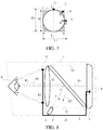
- FIG. 8 is a side cross-sectional view of another VR helmet provided by an exemplary embodiment of this application.
- the VR helmet may be a split-style VR head-mounted apparatus, and the apparatus body 1 of the VR helmet may comprise an apparatus interface 9, so that the apparatus interface 9 may be electrically connected to an electronic device such as a mobile phone or a tablet installed in the apparatus body 1.
- an electronic device such as a mobile phone or a tablet installed in the apparatus body 1.
- the electronic device may work as the VR playing component 5 in the apparatus body 1.
- the camera 4 and the infrared light source 8 in the apparatus body 1 may be connected to the apparatus interface 9 through a data line 10, so that when the electronic device connected to the apparatus interface 9 issues a switch control instruction, the camera 4 and the infrared light source 8 may receive the switch control instruction through the apparatus interface 9 and the data line 10 to perform a state switching operation in response to the switch control instruction.
- the electronic device may send a switch control instruction to the camera 4 and the infrared light source 8, thereby controlling the infrared light source 8 to provide infrared light compensation on the eye 6 and controlling the camera 4 to perform infrared image acquisition on the eye 6. That improves the controllability of infrared light compensation and infrared image acquisition.
- the switch control instruction may be sent to the camera 4 and the infrared light source 8 simultaneously.
- the switch control instruction may also be separately sent to the camera 4 or the infrared light source 8.
- the instruction may separately control the camera 4 to perform infrared image acquisition, and separately control the infrared light source 8 to provide infrared light compensation in case of poor light condition.
- the acquired infrared image may be transmitted to the processing module for processing.
- the camera 4 may transmit, through the apparatus interface 9 and the data line 10, the acquired infrared image to the aforementioned electronic device for processing by the electronic device.
- the VR helmet of this application may include other forms of VR head-mounted apparatuses other than the split-style VR head-mounted apparatus paired with an electronic device such as a mobile phone.
- the VR helmet may be paired with a PC host, a game console or another external apparatus, so the VR playing component 5 may be a display component built into the VR helmet, and the external apparatus is used for rendering VR display content.
- the VR helmet may be an integrated VR head-mounted apparatus. That is, the VR helmet may be able to play VR display content without resorting to any external apparatus.
- the VR playing component 5 is built-in in the VR helmet, and may have playing functions such as rendering and displaying of VR display content.
- first, second, and third may be used herein to describe various information, such information should not be limited to these terms. These terms are merely used for distinguishing information of the same type from each other.
- first information may also be referred to as second information, and similarly, second information may also be referred to as first information.
- second information may also be referred to as first information.
- the term “if' as used herein may be interpreted as "when " or “upon " or "in response to determining.”
Abstract
Description
- This application relates to the technical field of virtual reality, and in particular, to a virtual reality head-mounted apparatus.
- Virtual reality (VR) technology is a technology that comprehensively utilizes a computer graphics system and various control interfaces to generate an interactive three-dimensional interaction environment on a computer to provide users with immersive experience. In related art, a user may wear a VR head-mounted apparatus, such as VR glasses or a VR helmet, or another VR apparatus, to obtain corresponding VR experience.
- However, due to unique characteristics of VR scenarios, technical solutions for traditional electronic devices such as mobile phones or PCs may not be applicable to VR scenarios. For example, to acquire an infrared image of an eye of a user wearing a VR apparatus, due to structural limitations within the VR apparatus, image acquisition conditions for conventional methods may be difficult to meet, resulting in difficulties to successfully complete the corresponding tasks such as biometric recognition, eye tracking, etc.
- In view of these limitations, this application provides a VR head-mounted apparatus, which can improve the acquisition accuracy for an infrared image of an eye of a user.
- To achieve the aforementioned objective, this application provides the following technical solutions.
- According to a first aspect of this application, a VR head-mounted apparatus is provided. The VR head-mounted apparatus includes:
an apparatus body, wherein the apparatus body includes a convex lens, a camera and a partial-reflection partial-transmission lens for reflecting infrared light. The partial-reflection partial-transmission lens is located on a side of the convex lens away from a user, and the camera is located between the convex lens and the partial-reflection partial-transmission lens. A lens surface of the partial-reflection partial-transmission lens may be disposed obliquely, such that an infrared image of an eye of the user is reflected obliquely to the camera. - Optionally, the partial-reflection partial-transmission lens has a high transmittance for visible light and a low transmittance for infrared light.
- Optionally, the partial-reflection partial-transmission lens includes an infrared dichroic mirror.
- Optionally, the camera is located outside a display area of a VR display component in the VR head-mounted apparatus with respect to the convex lens.
- Optionally, the partial-reflection partial-transmission lens has a plate shape, the lens surface of the partial-reflection partial-transmission lens is inclined obliquely downward, the camera is located at a bottom of the apparatus body, and a lens of the camera is disposed obliquely upward.
- Optionally, the partial-reflection partial-transmission lens has a plate shape, the lens surface of the partial-reflection partial-transmission lens is inclined obliquely upward, the camera is located at a top of the apparatus body, and a lens of the camera is disposed obliquely downward.
- Optionally, the apparatus body may include two convex lenses, the partial-reflection partial-transmission lens is provided for at least one of the two convex lenses. The partial-reflection partial-transmission lens has a plate shape, the lens surface of the partial-reflection partial-transmission lens is horizontally inclined towards the two convex lenses, and the camera is located between the two convex lenses.
- Optionally, the apparatus body includes a baffle, and the baffle is located on a side of the convex lens away from the user and between the two convex lenses in the apparatus body. The partial-reflection partial-transmission lens is rectangular, two side edges of the partial-reflection partial-transmission lens in a horizontal direction abut against the baffle and an inner wall of the apparatus body respectively, and the camera is installed on a side surface of the baffle.
- Optionally, the apparatus further includes:
an infrared light source provided in the apparatus body, the infrared light source being located on a side of the convex lens close to the user, and providing infrared light compensation for an eye of the user. - Optionally, the infrared light source is distributed at a periphery of at least one convex lens, and the corresponding partial-reflection partial-transmission lens located at a side of the at least one convex lens away from the user.
- Optionally, an installation position of the infrared light source is within a coverage area of a circumscribed rectangle of the corresponding convex lens.
- Optionally, the apparatus further includes:
- an apparatus interface provided on the apparatus body, the apparatus interface being electrically connected to an electronic device installed in the apparatus body, the electronic device being used to play VR display content,
- the camera and the infrared light source being connected to the apparatus interface through a data line. Upon receiving a switch control instruction transmitted by the electronic device through the apparatus interface and the data line, the camera and the infrared light source perform a state switching operation in response to the switch control instruction, and the camera also transmits an acquired infrared image to the electronic device through the apparatus interface and the data line.
- As can be seen from the above technical solutions, in this application, a partial-reflection partial-transmission lens is provided in a VR head-mounted apparatus, and a lens surface of the partial-reflection partial-transmission lens is disposed obliquely. Without interfering with a user's viewing of VR display content, by obliquely reflecting an infrared image of an eye of the user, a deviation angle of a camera during the acquisition of the infrared image of the eye can be reduced, thus reducing the deformation and distortion of the infrared image of the eye, and helping to improve the acquisition accuracy for the infrared image of the eye.
-
-
FIG. 1 is a side cross-sectional view of a VR helmet provided by an exemplary embodiment of this application. -
FIG. 2 is a 3-D structural diagram of a VR helmet provided by an exemplary embodiment of this application. -
FIG. 3 is a 3-D structural diagram of another VR helmet provided by an exemplary embodiment of this application. -
FIG. 4 is a 3-D structural diagram of yet another VR helmet provided by an exemplary embodiment of this application. -
FIG. 5 is a side cross-sectional view of another VR helmet provided by an exemplary embodiment of this application. -
FIG. 6 is a structural diagram of a VR helmet, observed from a wearer's direction, provided by an exemplary embodiment of this application. -
FIG. 7 is a schematic diagram of a positional relationship between an infrared light source and a convex lens provided by an exemplary embodiment of this application. -
FIG. 8 is a side cross-sectional view of yet another VR helmet provided by an exemplary embodiment of this application. - The following embodiments are provided, using a VR helmet as an example, to introduce the related structure of a VR head-mounted apparatus of this application.
-
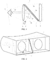
FIG. 1 is a side cross-sectional view of a VR helmet provided by an exemplary embodiment of this application. As shown inFIG. 1 , the VR helmet may include: anapparatus body 1. Theapparatus body 1 may include aconvex lens 2 and aVR playing component 5. Further, theapparatus body 1 may further include a partial-reflection partial-transmission lens 3 for reflecting infrared light. The partial-reflection partial-transmission lens 3 is located on a side of theconvex lens 2 away from a user (i.e., the partial-reflection partial-transmission lens 3 is located between theconvex lens 2 and the VR playing component 5). Since the partial-reflection partial-transmission lens 3 has a high transmittance for visible light (relative to infrared light) and a low transmittance for infrared light (relative to visible light), VR display content played by theVR playing component 5 may, in a form of visible light S1, go through the partial-reflection partial-transmission lens 3 almost unaffected, and an eye 6 of the user receives the visible light S1 to view the VR display content. Infrared light S2 emitted from the eye 6 of the user is mostly, if not completely, reflected by the partial-reflection partial-transmission lens 3. The reflected infrared light S2' is acquired by acamera 4 located between theconvex lens 2 and the partial-reflection partial-transmission lens 3, and the reflected infrared light S2' may form an infrared image of the eye 6, so as to achieve functions such as eye tracking and iris recognition. The camera 6 may be an infrared radiation (IR) camera or a red-green-blue (RGB)-IR integrated camera, which is not limited in this application. The camera 6 may include a variable-focus functional component that enables the camera 6 to achieve auto-focusing during image acquisition, thereby performing an acquisition operation on an infrared image of the eye 6 more quickly and accurately. - In this embodiment, the partial-reflection partial-
transmission lens 3 for reflecting infrared light refers to a lens having a low transmittance for an infrared spectrum and a high transmittance for other spectra (e.g., visible light). By blocking most, if not all, of light in the low-transmittance infrared spectrum, the partial-reflection partial-transmission lens 3 reflects light in the infrared spectrum (i.e., "partial-reflection"). Meanwhile, most, if not all, of light in other spectra such as high-transmittance visible light can be transmitted through the partial-reflection partial-transmission lens 3, minimizing the impact of the partial-reflection partial-transmission lens 3 on light in other spectra such as visible light (i.e., "partial-transmission"). - For example, the aforementioned partial-reflection partial-
transmission lens 3 for reflecting infrared light may be an infrared dichroic mirror, such that a visible spectrum may be almost completely transmitted and an infrared spectrum may be almost completely reflected. Specifically, in one case, an infrared reflective film such as a TiO2-Ag-TiO2 infrared reflective film or a ZnS-Ag-ZnS infrared reflective film may be coated on a surface of an optical lens of high light transmittance for visible light (the visible spectrum may be almost completely transmitted), thereby forming the infrared dichroic mirror. In another example, a lens may be entirely made of the aforementioned infrared reflective film or a similar preparation material to form the infrared dichroic mirror. - More specifically, a
lens surface 30 of the partial-reflection partial-transmission lens 3 is disposed obliquely, and positions of the partial-reflection partial-transmission lens 3 and thecamera 4 may be arranged, such that thelens surface 30 of the partial-reflection partial-transmission lens 3 can obliquely reflect the infrared light S2 corresponding to the infrared image of the eye 6 towards thecamera 4 to form the reflected infrared light S2'. Then, assuming that an angle α between thecamera 4 and the infrared light S2 is maintained, and since thelens surface 30 of the partial-reflection partial-transmission lens 3 is disposed obliquely, the infrared light S2 is reflected toward thecamera 4 to form the reflected infrared light S2', such that an angle β between thecamera 4 and the reflected infrared light S2' is inevitably smaller than the aforementioned angle α. That reduces the possible deformation and distortion of the infrared image of an eye acquired by thecamera 4, which helps to improve the acquisition accuracy for the infrared image of the eye 6, and to further improve the accuracy and precision of subsequent processing such as iris recognition and eye tracking. - In an actual case, inclination angles of the partial-reflection partial-
transmission lens 3 and thecamera 4 may be determined according to an internal space of theapparatus body 1. For example, the inclination angle of the partial-reflection partial-transmission lens 3 may be 45°, and a pointing direction of a lens of thecamera 4 may be perpendicular or substantially perpendicular to the partial-reflection partial-transmission lens 3, which is not limited in this application. - Additionally, since the
camera 4 is located between theconvex lens 2 and theVR playing component 5, that is, an installation position of thecamera 4 is located on a propagation line of the visible light S1, the installation position of thecamera 4 may be properly limited to avoid blocking the visible light S1. For example, as shown inFIG. 1 , thecamera 4 may be located, to the fullest extent possible, further away from a display area (for example, the display area may be indicated by an upper boundary T1 and a lower boundary T2 shown inFIG. 1 ) of the VR playing component 5 (i.e., a VR display component in the VR head-mounted apparatus) with respect to theconvex lens 2. - When the relative positional relationship among the
convex lens 2, the partial-reflection partial-transmission lens 3, thecamera 4, and theVR playing component 5 remains unchanged, the partial-reflection partial-transmission lens 3 and thecamera 4 may have various installation modes in the VR helmet, which will be described in the following examples. - In one embodiment, as shown in
FIG. 2 , when the partial-reflection partial-transmission lens 3 has a plate shape, the lens surface of the partial-reflection partial-transmission lens 3 may be inclined obliquely downward. For example, within a space between theconvex lens 2 and theVR playing component 5, the partial-reflection partial-transmission lens 3 may have its upper edge abut against a top inner side of the space, and its lower edge abut against a bottom outer side of the space. Thecamera 4 may be located at a bottom of theapparatus body 1, and the lens of thecamera 4 may be disposed obliquely upward to acquire the reflected infrared light S2' reflected by the partial-reflection partial-transmission lens 3. Although in a vertical direction, in order to avoid blocking the visible light S1, thecamera 4 has to be located outside the aforementioned display area and cannot be at the same height as the eye 6, in a horizontal direction (a direction perpendicular to the paper inFIG. 1 ), a horizontal angle between the lens of thecamera 4 and the infrared light S2 (or reflected infrared light S2') can be reduced, if not eliminated. For example, as shown inFIG. 2 , since the eye 6 of the user is usually located at the middle of theconvex lens 2 in the horizontal direction, thecamera 4 may be located at the middle of theconvex lens 2 in the horizontal direction, thereby reducing the probability that an infrared image of an eye is deformed or distorted. - In another embodiment, as shown in
FIG. 3 , when the partial-reflection partial-transmission lens 3 has a plate shape, the lens surface of the partial-reflection partial-transmission lens 3 may be inclined obliquely upward. For example, within a space between theconvex lens 2 and theVR playing component 5, the partial-reflection partial-transmission lens 3 may have its upper edge abut against a top outer side of the space, and its lower edge abut against a bottom inner side of the space. Thecamera 4 is located at a top of theapparatus body 1, and the lens of thecamera 4 may be disposed obliquely downward to acquire the reflected infrared light S2' reflected by the partial-reflection partial-transmission lens 3. Then, similarly to the embodiment shown inFIG. 2 , thecamera 4 may also be located at the middle of theconvex lens 2 in the horizontal direction to reduce, if not eliminate, the horizontal angle with the reflected infrared light S2', thereby reducing the probability that an infrared image of an eye is deformed or distorted. - In yet another embodiment, as shown in
FIG. 4 , when theapparatus body 1 includes two convex lenses 2 (corresponding to two eyes of the user respectively), the partial-reflection partial-transmission lens 3 may be provided for at least oneconvex lens 2 for performing infrared image reflection and acquisition on the corresponding eye of the user. For example, inFIG. 4 , the partial-reflection partial-transmission lens 3 is provided only for a rightconvex lens 2 corresponding to a right eye of the user, and not for a leftconvex lens 2 corresponding to a left eye of the user. When the partial-reflection partial-transmission lens 3 has a plate shape, the lens surface of the partial-reflection partial-transmission lens 3 may be inclined horizontally towards the twoconvex lenses 2, and thecamera 4 is located between the twoconvex lenses 2. For example, inFIG. 4 , the partial-reflection partial-transmission lens 3 is provided for the right eye of the user. Within a space between theconvex lens 2 and theVR playing component 5, the partial-reflection partial-transmission lens 3 may have its right side abut against a right interior of the space, and its left side abut against a left exterior of the space. That is, the lens surface of the partial-reflection partial-transmission lens 3 is inclined leftward, and the lens of thecamera 4 is disposed in a left-to-right orientation to acquire the reflected infrared light S2' from the partial-reflection partial-transmission lens 3. - More specifically, the
apparatus body 1 may include abaffle 7. Thebaffle 7 is located on a side of theconvex lens 2 away from the user, and located between the twoconvex lenses 2 in theapparatus body 1. In order to adapt to a cuboid space inside theapparatus body 1, the partial-reflection partial-transmission lens 3 may be rectangular. To install the partial-reflection partial-transmission lens 3, two side edges of the partial-reflection partial-transmission lens 3 in the horizontal direction may abut against thebaffle 7 and an inner wall of theapparatus body 1 respectively. Thecamera 4 may be installed on a side surface of thebaffle 7 and face the lens surface of the partial-reflection partial-transmission lens 3. - In the aforementioned embodiment of this application, since the VR helmet needs to provide the user with an immersive VR scenario and user experience, the entrance of external light should be minimized. Therefore it may be difficult to satisfy the image acquisition condition of the
camera 4 for the eye since light conditions inside theapparatus body 1 are poor after the user wears the VR helmet. To address this issue, this application further proposes the following technical solutions based on the aforementioned embodiments. - The VR helmet of this application, as shown in
FIG. 5 , may further include an infraredlight source 8 provided in theapparatus body 1. The infraredlight source 8 is distributed at a periphery of at least oneconvex lens 2, and provides infrared light compensation (the infraredlight source 8 emits infrared light such as R1 and R2 to the eye 6, as shown inFIG. 5 ) on an eye 6 of the user corresponding to the at least oneconvex lens 2. As shown inFIG. 6 , the VR helmet is usually configured with twoconvex lenses 2 corresponding to the eyes of a user. The infraredlight source 8 may be distributed at a periphery of one singleconvex lens 2. For example, the infrared light source may be distributed at a periphery of a rightconvex lens 2 inFIG. 6 to provide infrared light compensation on the right eye of the user, and not distributed at a periphery of a leftconvex lens 2. Certainly, in other embodiments, an infraredlight source 8 may be simultaneously disposed at peripheries of the twoconvex lenses 2 for infrared light compensation. Detail implementation is not limited in this application. - In fact, in the VR helmet, positions of the infrared
light source 8, thecamera 4, and the partial-reflection partial-transmission lens 3 are related with each other. For example, as shown inFIG. 6 , to perform eye tracking, iris recognition, etc. on the right eye of the user, at least one infraredlight source 8 may be disposed at the periphery of the rightconvex lens 2. Moreover, the partial-reflection partial-transmission lens 3 and thecamera 4 may be provided at a side of the rightconvex lens 2 away from the user to achieve corresponding infrared image acquisition. Similarly, to perform eye tracking, iris recognition, etc. on both eyes of the user,infrared light sources 8 may be disposed at the peripheries of the twoconvex lenses 2 simultaneously, and the partial-reflection partial-transmission lens 3 and thecamera 4 may be provided at a side of eachconvex lens 2 away from the user to achieve corresponding infrared image acquisition. - Although the embodiment shown in
FIG. 6 has fourinfrared light sources 8 distributed at a periphery of the rightconvex lens 2, it is only used as an example here. In fact, in the VR helmet of this application, one or more infraredlight sources 8 may be distributed at a periphery of each convex lens. The number of infraredlight sources 8 is not limited in this application. When there exist multiple infrared light sources 8 (e.g., when fourinfrared light sources 8 are distributed at a periphery of the rightconvex lens 2 as shown inFIG. 6 ), these infraredlight sources 8 may be, to the fullest extent possible, uniformly distributed to provide uniform light compensation for the eye 6. - Additionally, when the
apparatus body 1 includes theconvex lens 2, an external size of theapparatus body 1 is related to the space occupation of theconvex lens 2. For example, as shown inFIG. 7 , assuming theconvex lens 2 has a length of L in a horizontal direction (i.e., x-axis direction inFIG. 7 ), and a length of H in a vertical direction (i.e., y-axis direction inFIG. 7 , when theconvex lens 2 is a circle, L and H are equal to a diameter length of the circle). Then, the space occupation of theconvex lens 2 for theapparatus body 1 is related to values of L and H. That is, theapparatus body 1 may have a length of at least L in the horizontal direction, and a length of at least H in the vertical direction. In fact, when theapparatus body 1 has a substantially rectangular parallelepiped shape, an external size of theapparatus body 1 required by theconvex lens 2 is substantially the same as the external size of theapparatus body 1 required by a circumscribed rectangle (as shown inFIG. 7 , the circumscribed rectangle has a horizontal width of L and a vertical height of H) of theconvex lens 2. - In one embodiment, as shown in
FIG. 7 , when an installation position of the infraredlight source 8 is located within a coverage area of the circumscribed rectangle of theconvex lens 2, since the infraredlight source 8 needs to avoid blocking theconvex lens 2, the infraredlight source 8 should not be located within the convex lens 2 (e.g., point A), but should be located within a shaded area (e.g., point B) shown inFIG. 7 . In this case, a space needed by theapparatus body 1 that has the infraredlight source 8 may overlap with the circumscribed rectangle (or theconvex lens 2 itself), so that the infraredlight source 8 does not require additional space from theapparatus body 1. That helps to control or even reduce the size of theapparatus body 1 and the VR helmet, and prevent the VR helmet from being too bulky and cumbersome. - In another embodiment, as shown in
FIG. 7 , when the infraredlight source 8 is located at point C, an overall height of a combination of the infraredlight source 8 and theconvex lens 2 in the vertical direction increases from H to HI. That is, a space occupation requirement for theapparatus body 1 in the vertical direction increases from H to HI, and the VR helmet becomes thicker. Similarly, when the infraredlight source 8 is located at point D, an overall width of a combination of the infraredlight source 8 and theconvex lens 2 in the horizontal direction increases from L to L1. That is, a space occupation requirement for theapparatus body 1 in the horizontal direction increases from L to L1, and the VR helmet becomes wider. - Therefore, to the fullest extent possible, the infrared
light source 8 can be provided within the coverage area of the circumscribed rectangle of the correspondingconvex lens 2 to avoid increasing the space occupation requirement for theapparatus body 1, and to help control the space occupied by the VR helmet. -
FIG. 8 is a side cross-sectional view of another VR helmet provided by an exemplary embodiment of this application. As shown inFIG. 8 , the VR helmet may be a split-style VR head-mounted apparatus, and theapparatus body 1 of the VR helmet may comprise an apparatus interface 9, so that the apparatus interface 9 may be electrically connected to an electronic device such as a mobile phone or a tablet installed in theapparatus body 1. By using a processor or a graphics card chip, etc. for rendering, and using a screen component for content displaying, the electronic device may work as theVR playing component 5 in theapparatus body 1. - Further, the
camera 4 and the infraredlight source 8 in theapparatus body 1 may be connected to the apparatus interface 9 through adata line 10, so that when the electronic device connected to the apparatus interface 9 issues a switch control instruction, thecamera 4 and the infraredlight source 8 may receive the switch control instruction through the apparatus interface 9 and thedata line 10 to perform a state switching operation in response to the switch control instruction. In other words, based on the user control to the electronic device or an application program running on the electronic device, the electronic device may send a switch control instruction to thecamera 4 and the infraredlight source 8, thereby controlling the infraredlight source 8 to provide infrared light compensation on the eye 6 and controlling thecamera 4 to perform infrared image acquisition on the eye 6. That improves the controllability of infrared light compensation and infrared image acquisition. - The switch control instruction may be sent to the
camera 4 and the infraredlight source 8 simultaneously. Alternatively, the switch control instruction may also be separately sent to thecamera 4 or the infraredlight source 8. For example, the instruction may separately control thecamera 4 to perform infrared image acquisition, and separately control the infraredlight source 8 to provide infrared light compensation in case of poor light condition. - Additionally, after the
camera 4 completes the infrared image acquisition, if the VR helmet comprises a processing module, the acquired infrared image may be transmitted to the processing module for processing. Alternatively, thecamera 4 may transmit, through the apparatus interface 9 and thedata line 10, the acquired infrared image to the aforementioned electronic device for processing by the electronic device. - Certainly, the VR helmet of this application may include other forms of VR head-mounted apparatuses other than the split-style VR head-mounted apparatus paired with an electronic device such as a mobile phone. For example, for the split-style VR head-mounted apparatus, the VR helmet may be paired with a PC host, a game console or another external apparatus, so the
VR playing component 5 may be a display component built into the VR helmet, and the external apparatus is used for rendering VR display content. For another example, the VR helmet may be an integrated VR head-mounted apparatus. That is, the VR helmet may be able to play VR display content without resorting to any external apparatus. TheVR playing component 5 is built-in in the VR helmet, and may have playing functions such as rendering and displaying of VR display content. - It should also be noted that the terms "include", "comprise" and any other variants mean to cover the non-exclusive inclusion. Thereby, the process, method, article, or device which include a series of elements not only include those elements, but also include other elements which are not clearly listed, or include the inherent elements of the process, method, article and device. Without further limitation, the element defined by a phrase "include one......" does not exclude other same elements in the process, method, article or device which include the element.
- Reference will now be made in detail to exemplary embodiments, examples of which are illustrated in the accompanying drawings. The following description refers to the accompanying drawings in which the same numbers in different drawings represent the same or similar elements unless otherwise represented. The implementations set forth in the following description of exemplary embodiments do not represent all implementations consistent with this application. Instead, they are merely examples of apparatuses and methods consistent with aspects related to this application as recited in the appended claims.
- The terms used in this application are merely for the purpose of describing specific embodiments, and are not intended to limit this application. The terms "a", "said" and "the" of singular forms used in this application and the appended claims are also intended to include plural forms, unless otherwise specified in the context clearly. It should also be understood that, the term "and/or" used herein indicates and includes any or all possible combinations of one or more associated listed items.
- It should be understood that although the terms such as first, second, and third may be used herein to describe various information, such information should not be limited to these terms. These terms are merely used for distinguishing information of the same type from each other. For example, within the scope of this application, first information may also be referred to as second information, and similarly, second information may also be referred to as first information. Depending on the context, the term "if' as used herein may be interpreted as "when ..." or "upon ..." or "in response to determining."
- The above descriptions are merely exemplary embodiments of this application, but are not intended to limit this application. Any modification, equivalent replacement, or improvement made without departing from the spirit and principle of this application should fall within the protection scope of this application.
Claims (12)
- A virtual reality (VR) head-mounted apparatus, comprising:
an apparatus body, the apparatus body comprising a convex lens, a camera and a partial-reflection partial-transmission lens for reflecting infrared light, the partial-reflection partial-transmission lens being located on a side of the convex lens away from a user, the camera being located between the convex lens and the partial-reflection partial-transmission lens, and a lens surface of the partial-reflection partial-transmission lens being disposed obliquely, such that an infrared image of an eye of the user is obliquely reflected to the camera. - The apparatus according to claim 1, wherein the partial-reflection partial-transmission lens has a high transmittance for visible light and a low transmittance for infrared light.
- The apparatus according to claim 1, wherein the partial-reflection partial-transmission lens comprises an infrared dichroic mirror.
- The apparatus according to claim 1, wherein the camera is located outside a display area of a VR display component in the VR head-mounted apparatus with respect to the convex lens.
- The apparatus according to claim 1, wherein the partial-reflection partial-transmission lens has a plate shape, the lens surface of the partial-reflection partial-transmission lens is inclined obliquely downward, the camera is located at a bottom of the apparatus body, and a lens of the camera is disposed obliquely upward.
- The apparatus according to claim 1, wherein the partial-reflection partial-transmission lens has a plate shape, the lens surface of the partial-reflection partial-transmission lens is inclined obliquely upward, the camera is located at a top of the apparatus body, and a lens of the camera is disposed obliquely downward.
- The apparatus according to claim 1, wherein the apparatus body comprises two convex lenses, the partial-reflection partial-transmission lens is provided for at least one of the two convex lenses, and the partial-reflection partial-transmission lens has a plate shape, the lens surface of the partial-reflection partial-transmission lens is horizontally inclined towards the two convex lenses, and the camera is located between the two convex lenses.
- The apparatus according to claim 7, wherein the apparatus body comprises a baffle, the baffle is located on a side of the convex lens away from the user, and located between the two convex lenses in the apparatus body; the partial-reflection partial-transmission lens is rectangular, two side edges of the partial-reflection partial-transmission lens in a horizontal direction abut against the baffle and an inner wall of the apparatus body respectively; and the camera is installed on a side surface of the baffle.
- The apparatus according to claim 1, further comprising:
an infrared light source provided in the apparatus body, the infrared light source being located on a side of the convex lens close to the user, and providing infrared light compensation for an eye of the user. - The apparatus according to claim 9, wherein the infrared light source is distributed at a periphery of at least one convex lens, and the partial-reflection partial-transmission lens is located at a side of the at least one convex lens away from the user.
- The apparatus according to claim 10, wherein an installation position of the infrared light source is within a coverage area of a circumscribed rectangle of the corresponding convex lens.
- The apparatus according to claim 1, further comprising:an apparatus interface provided on the apparatus body, the apparatus interface being electrically connected to an electronic device installed in the apparatus body, the electronic device being used to play VR display content,the camera and the infrared light source being connected to the apparatus interface through a data line, wherein upon receiving a switch control instruction transmitted by the electronic device through the apparatus interface and the data line, the camera and the infrared light source perform a state switching operation in response to the switch control instruction, and the camera also transmits an acquired infrared image to the electronic device through the apparatus interface and the data line.
Priority Applications (1)
| Application Number | Priority Date | Filing Date | Title |
|---|---|---|---|
| PL18756597T PL3564731T3 (en) | 2017-02-27 | 2018-02-26 | Virtual reality head-mounted apparatus |
Applications Claiming Priority (2)
| Application Number | Priority Date | Filing Date | Title |
|---|---|---|---|
| CN201710108672.8A CN106932904A (en) | 2017-02-27 | 2017-02-27 | Virtual reality helmet |
| PCT/CN2018/077281 WO2018153368A1 (en) | 2017-02-27 | 2018-02-26 | Virtual reality head-mounted apparatus |
Publications (3)
| Publication Number | Publication Date |
|---|---|
| EP3564731A1 true EP3564731A1 (en) | 2019-11-06 |
| EP3564731A4 EP3564731A4 (en) | 2020-01-29 |
| EP3564731B1 EP3564731B1 (en) | 2020-09-09 |
Family
ID=59423238
Family Applications (1)
| Application Number | Title | Priority Date | Filing Date |
|---|---|---|---|
| EP18756597.3A Active EP3564731B1 (en) | 2017-02-27 | 2018-02-26 | Virtual reality head-mounted apparatus |
Country Status (12)
| Country | Link |
|---|---|
| US (1) | US10996477B2 (en) |
| EP (1) | EP3564731B1 (en) |
| JP (1) | JP6999687B2 (en) |
| KR (1) | KR102397064B1 (en) |
| CN (1) | CN106932904A (en) |
| ES (1) | ES2826888T3 (en) |
| MY (1) | MY195276A (en) |
| PH (1) | PH12019501870A1 (en) |
| PL (1) | PL3564731T3 (en) |
| SG (1) | SG11201907252PA (en) |
| TW (1) | TWI664443B (en) |
| WO (1) | WO2018153368A1 (en) |
Families Citing this family (16)
| Publication number | Priority date | Publication date | Assignee | Title |
|---|---|---|---|---|
| CN106569339B (en) * | 2016-11-08 | 2019-11-15 | 歌尔科技有限公司 | The control method of VR helmet and VR helmet |
| CN106932904A (en) | 2017-02-27 | 2017-07-07 | 阿里巴巴集团控股有限公司 | Virtual reality helmet |
| US10788677B2 (en) * | 2017-10-03 | 2020-09-29 | Facebook Technologies, Llc | Fresnel assembly for light redirection in eye tracking systems |
| WO2019113942A1 (en) * | 2017-12-15 | 2019-06-20 | 歌尔科技有限公司 | Vr head-mounted display device and display method |
| US10845594B1 (en) | 2017-12-21 | 2020-11-24 | Facebook Technologies, Llc | Prism based light redirection system for eye tracking systems |
| CN108169842B (en) * | 2018-01-02 | 2020-06-26 | 京东方科技集团股份有限公司 | Waveguide assembly for intelligent display wearable device and intelligent display wearable device |
| KR102493028B1 (en) * | 2018-02-23 | 2023-01-31 | 삼성전자주식회사 | An electronic device and a method for acquiring an image corresponding to infra-red using a camera module comprising a lens capable of absolving visible light |
| CN108378819B (en) * | 2018-05-02 | 2023-10-27 | 重庆贝奥新视野医疗设备有限公司 | Fundus camera and virtual reality imaging apparatus |
| CN108521564A (en) * | 2018-05-25 | 2018-09-11 | 嘉兴玄视信息科技有限公司 | A kind of virtual reality all-in-one machine |
| CN109816675A (en) * | 2018-12-28 | 2019-05-28 | 歌尔股份有限公司 | Detection method, detection device and the storage medium of object |
| CN109725416B (en) * | 2019-03-13 | 2021-09-21 | 北京七鑫易维信息技术有限公司 | Eyeball tracking optical system, head-mounted equipment and imaging method |
| US11844958B2 (en) * | 2019-05-14 | 2023-12-19 | Twenty Twenty Therapeutics Llc | Gland treatment devices and methods for treating dry eye disease |
| CN111580278B (en) * | 2020-06-11 | 2022-06-17 | 京东方科技集团股份有限公司 | AR or VR glasses |
| TWI738473B (en) * | 2020-08-19 | 2021-09-01 | 宏達國際電子股份有限公司 | Head mounted display apparatus and eye-tracking apparatus thereof |
| EP4202531A4 (en) | 2020-11-24 | 2024-03-20 | Samsung Electronics Co Ltd | Augmented reality wearable electronic device comprising camera |
| KR20220072066A (en) * | 2020-11-24 | 2022-06-02 | 삼성전자주식회사 | Augmented reality wearable electronic device including camera |
Family Cites Families (63)
| Publication number | Priority date | Publication date | Assignee | Title |
|---|---|---|---|---|
| JPH06121254A (en) * | 1992-10-06 | 1994-04-28 | Olympus Optical Co Ltd | Head mount type display device |
| JPH08205200A (en) * | 1995-01-27 | 1996-08-09 | Olympus Optical Co Ltd | Three-dimensional image pickup device |
| US6043799A (en) * | 1998-02-20 | 2000-03-28 | University Of Washington | Virtual retinal display with scanner array for generating multiple exit pupils |
| JPH11249588A (en) * | 1998-02-27 | 1999-09-17 | Shimadzu Corp | Head-mounted display |
| JP2008241822A (en) | 2007-03-26 | 2008-10-09 | Mitsubishi Electric Corp | Image display device |
| US20100149073A1 (en) * | 2008-11-02 | 2010-06-17 | David Chaum | Near to Eye Display System and Appliance |
| WO2011084895A1 (en) | 2010-01-08 | 2011-07-14 | Kopin Corporation | Video eyewear for smart phone games |
| US9406166B2 (en) * | 2010-11-08 | 2016-08-02 | Seereal Technologies S.A. | Display device, in particular a head-mounted display, based on temporal and spatial multiplexing of hologram tiles |
| JP2012168346A (en) * | 2011-02-15 | 2012-09-06 | Casio Comput Co Ltd | Browsing device |
| US8692738B2 (en) | 2011-06-10 | 2014-04-08 | Disney Enterprises, Inc. | Advanced Pepper's ghost projection system with a multiview and multiplanar display |
| US9268024B1 (en) * | 2012-01-06 | 2016-02-23 | Google Inc. | Expectation maximization to determine position of ambient glints |
| US9147111B2 (en) | 2012-02-10 | 2015-09-29 | Microsoft Technology Licensing, Llc | Display with blocking image generation |
| US9788714B2 (en) | 2014-07-08 | 2017-10-17 | Iarmourholdings, Inc. | Systems and methods using virtual reality or augmented reality environments for the measurement and/or improvement of human vestibulo-ocular performance |
| CN103293673B (en) * | 2013-06-03 | 2015-04-01 | 卫荣杰 | Cap integrated with display, eye tracker and iris recognition instrument |
| JP2015015563A (en) | 2013-07-04 | 2015-01-22 | セイコーエプソン株式会社 | Image display device |
| KR20150027651A (en) * | 2013-09-04 | 2015-03-12 | (주)판도라나인 | Head mounted device for installing smartphone |
| US9993335B2 (en) * | 2014-01-08 | 2018-06-12 | Spy Eye, Llc | Variable resolution eye mounted displays |
| AU2015297035B2 (en) | 2014-05-09 | 2018-06-28 | Google Llc | Systems and methods for biomechanically-based eye signals for interacting with real and virtual objects |
| US9706910B1 (en) * | 2014-05-29 | 2017-07-18 | Vivid Vision, Inc. | Interactive system for vision assessment and correction |
| JP6539654B2 (en) * | 2014-06-27 | 2019-07-03 | フォーブ インコーポレーテッド | Gaze detection device |
| CN104407440A (en) * | 2014-11-19 | 2015-03-11 | 东南大学 | Holographic display device with sight tracking function |
| US9684172B2 (en) * | 2014-12-03 | 2017-06-20 | Osterhout Group, Inc. | Head worn computer display systems |
| US9791924B2 (en) | 2014-12-23 | 2017-10-17 | Mediatek Inc. | Eye tracking with mobile device in a head-mounted display |
| WO2016103525A1 (en) | 2014-12-27 | 2016-06-30 | 株式会社Fove | Head mount display |
| WO2016130666A1 (en) * | 2015-02-10 | 2016-08-18 | LAFORGE Optical, Inc. | Lens for displaying a virtual image |
| US10054797B2 (en) | 2015-02-12 | 2018-08-21 | Google Llc | Combining a high resolution narrow field display and a mid resolution wide field display |
| WO2016157485A1 (en) * | 2015-04-01 | 2016-10-06 | フォーブ インコーポレーテッド | Head mounted display |
| WO2016157486A1 (en) * | 2015-04-01 | 2016-10-06 | フォーブ インコーポレーテッド | Head mounted display |
| US10437327B2 (en) * | 2015-05-08 | 2019-10-08 | Apple Inc. | Eye tracking device and method for operating an eye tracking device |
| US20160349509A1 (en) | 2015-05-26 | 2016-12-01 | Microsoft Technology Licensing, Llc | Mixed-reality headset |
| US20160378176A1 (en) * | 2015-06-24 | 2016-12-29 | Mediatek Inc. | Hand And Body Tracking With Mobile Device-Based Virtual Reality Head-Mounted Display |
| JP6899816B2 (en) | 2015-07-23 | 2021-07-07 | ニュー ジャージー インスティチュート オブ テクノロジー | Methods, systems, and devices for the treatment of binocular vision dysfunction |
| CN105068249A (en) | 2015-08-03 | 2015-11-18 | 众景视界(北京)科技有限公司 | Holographic intelligent glasses |
| JP2016127587A (en) * | 2015-09-03 | 2016-07-11 | 株式会社Fove | Head-mounted display |
| JP2019506017A (en) | 2015-11-06 | 2019-02-28 | フェイスブック・テクノロジーズ・リミテッド・ライアビリティ・カンパニーFacebook Technologies, Llc | Eye tracking using optical flow |
| CN205139485U (en) * | 2015-11-30 | 2016-04-06 | 上海圆津电子科技有限公司 | Virtual reality glasses of three -dimensional formation of image |
| US9910282B2 (en) * | 2015-12-28 | 2018-03-06 | Oculus Vr, Llc | Increasing field of view of head-mounted display using a mirror |
| WO2017115081A1 (en) * | 2015-12-30 | 2017-07-06 | Daqri Holographics Ltd | Near eye dynamic holography |
| CN106214118A (en) * | 2016-01-28 | 2016-12-14 | 北京爱生科贸有限公司 | A kind of ocular movement based on virtual reality monitoring system |
| US10459230B2 (en) | 2016-02-02 | 2019-10-29 | Disney Enterprises, Inc. | Compact augmented reality / virtual reality display |
| US10424295B2 (en) | 2016-02-03 | 2019-09-24 | Disney Enterprises, Inc. | Calibration of virtual image displays |
| US10151924B2 (en) * | 2016-02-10 | 2018-12-11 | Nvidia Corporation | Holographic reflective slim virtual/augmented reality display system and method |
| US10228564B2 (en) | 2016-03-03 | 2019-03-12 | Disney Enterprises, Inc. | Increasing returned light in a compact augmented reality/virtual reality display |
| US10455214B2 (en) | 2016-03-03 | 2019-10-22 | Disney Enterprises, Inc. | Converting a monocular camera into a binocular stereo camera |
| CN205594581U (en) * | 2016-04-06 | 2016-09-21 | 北京七鑫易维信息技术有限公司 | Module is tracked to eyeball of video glasses |
| US9922464B2 (en) | 2016-05-10 | 2018-03-20 | Disney Enterprises, Inc. | Occluded virtual image display |
| US10095307B2 (en) * | 2016-05-13 | 2018-10-09 | Google Llc | Eye tracking systems and methods for virtual reality environments |
| CN106406509B (en) * | 2016-05-16 | 2023-08-01 | 上海青研科技有限公司 | Head-mounted eye-control virtual reality equipment |
| US10151927B2 (en) | 2016-05-31 | 2018-12-11 | Falcon's Treehouse, Llc | Virtual reality and augmented reality head set for ride vehicle |
| US10429647B2 (en) * | 2016-06-10 | 2019-10-01 | Facebook Technologies, Llc | Focus adjusting virtual reality headset |
| CN105929543A (en) * | 2016-06-18 | 2016-09-07 | 深圳晨芯时代科技有限公司 | Virtual reality device, virtual reality glass box thereof and virtual reality plate |
| CN205942608U (en) * | 2016-06-30 | 2017-02-08 | 上海青研科技有限公司 | A integration mirror cup that is used for eyeball to track and iris discernment |
| CN105955491B (en) * | 2016-06-30 | 2020-07-10 | 北京上古视觉科技有限公司 | VR glasses with eye accuse and iris recognition function |
| US9996984B2 (en) | 2016-07-05 | 2018-06-12 | Disney Enterprises, Inc. | Focus control for virtual objects in augmented reality (AR) and virtual reality (VR) displays |
| KR102520143B1 (en) * | 2016-07-25 | 2023-04-11 | 매직 립, 인코포레이티드 | Light field processor system |
| DE202016104179U1 (en) | 2016-07-29 | 2016-08-12 | Christian Hildebrandt | Output device for stereoscopic image reproduction |
| US10203489B2 (en) * | 2016-08-02 | 2019-02-12 | Apple Inc. | Optical system for head-mounted display |
| CN106325521B (en) | 2016-08-31 | 2018-06-29 | 北京小米移动软件有限公司 | Test virtual reality head shows the method and device of device software |
| US10300372B2 (en) | 2016-09-30 | 2019-05-28 | Disney Enterprises, Inc. | Virtual blaster |
| WO2018067357A2 (en) | 2016-10-05 | 2018-04-12 | Magic Leap, Inc. | Periocular test for mixed reality calibration |
| CN106406543A (en) * | 2016-11-23 | 2017-02-15 | 长春中国光学科学技术馆 | VR scene conversion device controlled by human eyes |
| CN206573783U (en) * | 2017-02-27 | 2017-10-20 | 阿里巴巴集团控股有限公司 | Virtual reality helmet |
| CN106932904A (en) * | 2017-02-27 | 2017-07-07 | 阿里巴巴集团控股有限公司 | Virtual reality helmet |
-
2017
- 2017-02-27 CN CN201710108672.8A patent/CN106932904A/en active Pending
- 2017-11-17 TW TW106139874A patent/TWI664443B/en active
-
2018
- 2018-02-26 KR KR1020197024389A patent/KR102397064B1/en active IP Right Grant
- 2018-02-26 PL PL18756597T patent/PL3564731T3/en unknown
- 2018-02-26 JP JP2019546272A patent/JP6999687B2/en active Active
- 2018-02-26 ES ES18756597T patent/ES2826888T3/en active Active
- 2018-02-26 EP EP18756597.3A patent/EP3564731B1/en active Active
- 2018-02-26 SG SG11201907252PA patent/SG11201907252PA/en unknown
- 2018-02-26 MY MYPI2019004379A patent/MY195276A/en unknown
- 2018-02-26 WO PCT/CN2018/077281 patent/WO2018153368A1/en unknown
-
2019
- 2019-07-30 US US16/526,228 patent/US10996477B2/en active Active
- 2019-08-13 PH PH12019501870A patent/PH12019501870A1/en unknown
Also Published As
| Publication number | Publication date |
|---|---|
| KR20190105642A (en) | 2019-09-17 |
| CN106932904A (en) | 2017-07-07 |
| KR102397064B1 (en) | 2022-05-11 |
| JP2020508494A (en) | 2020-03-19 |
| WO2018153368A1 (en) | 2018-08-30 |
| SG11201907252PA (en) | 2019-09-27 |
| TW201831951A (en) | 2018-09-01 |
| MY195276A (en) | 2023-01-12 |
| ES2826888T3 (en) | 2021-05-19 |
| US10996477B2 (en) | 2021-05-04 |
| PL3564731T3 (en) | 2021-01-25 |
| JP6999687B2 (en) | 2022-01-19 |
| PH12019501870A1 (en) | 2020-06-01 |
| US20190353909A1 (en) | 2019-11-21 |
| EP3564731A4 (en) | 2020-01-29 |
| EP3564731B1 (en) | 2020-09-09 |
| TWI664443B (en) | 2019-07-01 |
Similar Documents
| Publication | Publication Date | Title |
|---|---|---|
| EP3564731B1 (en) | Virtual reality head-mounted apparatus | |
| EP3557308B1 (en) | Virtual reality head-mounted apparatus | |
| US11079839B2 (en) | Eye tracking device and eye tracking method applied to video glasses and video glasses | |
| US11016293B2 (en) | Virtual reality head-mounted apparatus | |
| CN112470163A (en) | Intra-field illumination and imaging for eye tracking | |
| US11500607B2 (en) | Using detected pupil location to align optical components of a head-mounted display | |
| KR102380809B1 (en) | Head-worn devices for virtual reality | |
| CN108398788B (en) | Eye tracking device and virtual reality imaging device | |
| US11675192B2 (en) | Hybrid coupling diffractive optical element | |
| WO2018153367A1 (en) | Virtual reality head-mounted apparatus | |
| US11733952B2 (en) | Wearable electronic device including display, method for controlling display, and system including wearable electronic device and case | |
| CN206573783U (en) | Virtual reality helmet | |
| WO2023062995A1 (en) | Head-mount device and light guide device | |
| KR20240029475A (en) | Apparatus and method for registering and releasing an authentication pattern using objects | |
| KR20240018990A (en) | Method and device to authenticate user in augmented reality |
Legal Events
| Date | Code | Title | Description |
|---|---|---|---|
| STAA | Information on the status of an ep patent application or granted ep patent |
Free format text: STATUS: THE INTERNATIONAL PUBLICATION HAS BEEN MADE |
|
| PUAI | Public reference made under article 153(3) epc to a published international application that has entered the european phase |
Free format text: ORIGINAL CODE: 0009012 |
|
| STAA | Information on the status of an ep patent application or granted ep patent |
Free format text: STATUS: REQUEST FOR EXAMINATION WAS MADE |
|
| 17P | Request for examination filed |
Effective date: 20190731 |
|
| AK | Designated contracting states |
Kind code of ref document: A1 Designated state(s): AL AT BE BG CH CY CZ DE DK EE ES FI FR GB GR HR HU IE IS IT LI LT LU LV MC MK MT NL NO PL PT RO RS SE SI SK SM TR |
|
| AX | Request for extension of the european patent |
Extension state: BA ME |
|
| STAA | Information on the status of an ep patent application or granted ep patent |
Free format text: STATUS: EXAMINATION IS IN PROGRESS |
|
| A4 | Supplementary search report drawn up and despatched |
Effective date: 20200108 |
|
| RIC1 | Information provided on ipc code assigned before grant |
Ipc: G02B 27/01 20060101AFI20191220BHEP Ipc: G06F 3/01 20060101ALI20191220BHEP Ipc: G02B 27/14 20060101ALI20191220BHEP Ipc: G02B 27/00 20060101ALI20191220BHEP |
|
| 17Q | First examination report despatched |
Effective date: 20200124 |
|
| DAV | Request for validation of the european patent (deleted) | ||
| DAX | Request for extension of the european patent (deleted) | ||
| GRAP | Despatch of communication of intention to grant a patent |
Free format text: ORIGINAL CODE: EPIDOSNIGR1 |
|
| STAA | Information on the status of an ep patent application or granted ep patent |
Free format text: STATUS: GRANT OF PATENT IS INTENDED |
|
| GRAS | Grant fee paid |
Free format text: ORIGINAL CODE: EPIDOSNIGR3 |
|
| GRAA | (expected) grant |
Free format text: ORIGINAL CODE: 0009210 |
|
| STAA | Information on the status of an ep patent application or granted ep patent |
Free format text: STATUS: THE PATENT HAS BEEN GRANTED |
|
| INTG | Intention to grant announced |
Effective date: 20200723 |
|
| AK | Designated contracting states |
Kind code of ref document: B1 Designated state(s): AL AT BE BG CH CY CZ DE DK EE ES FI FR GB GR HR HU IE IS IT LI LT LU LV MC MK MT NL NO PL PT RO RS SE SI SK SM TR |
|
| REG | Reference to a national code |
Ref country code: GB Ref legal event code: FG4D |
|
| REG | Reference to a national code |
Ref country code: AT Ref legal event code: REF Ref document number: 1312324 Country of ref document: AT Kind code of ref document: T Effective date: 20200915 Ref country code: CH Ref legal event code: EP |
|
| REG | Reference to a national code |
Ref country code: CH Ref legal event code: NV Representative=s name: SERVOPATENT GMBH, CH Ref country code: IE Ref legal event code: FG4D |
|
| REG | Reference to a national code |
Ref country code: DE Ref legal event code: R096 Ref document number: 602018007735 Country of ref document: DE |
|
| REG | Reference to a national code |
Ref country code: FI Ref legal event code: FGE |
|
| REG | Reference to a national code |
Ref country code: NL Ref legal event code: FP |
|
| RAP2 | Party data changed (patent owner data changed or rights of a patent transferred) |
Owner name: ADVANCED NEW TECHNOLOGIES CO., LTD. |
|
| REG | Reference to a national code |
Ref country code: LT Ref legal event code: MG4D |
|
| PG25 | Lapsed in a contracting state [announced via postgrant information from national office to epo] |
Ref country code: GR Free format text: LAPSE BECAUSE OF FAILURE TO SUBMIT A TRANSLATION OF THE DESCRIPTION OR TO PAY THE FEE WITHIN THE PRESCRIBED TIME-LIMIT Effective date: 20201210 Ref country code: BG Free format text: LAPSE BECAUSE OF FAILURE TO SUBMIT A TRANSLATION OF THE DESCRIPTION OR TO PAY THE FEE WITHIN THE PRESCRIBED TIME-LIMIT Effective date: 20201209 Ref country code: SE Free format text: LAPSE BECAUSE OF FAILURE TO SUBMIT A TRANSLATION OF THE DESCRIPTION OR TO PAY THE FEE WITHIN THE PRESCRIBED TIME-LIMIT Effective date: 20200909 Ref country code: HR Free format text: LAPSE BECAUSE OF FAILURE TO SUBMIT A TRANSLATION OF THE DESCRIPTION OR TO PAY THE FEE WITHIN THE PRESCRIBED TIME-LIMIT Effective date: 20200909 Ref country code: LT Free format text: LAPSE BECAUSE OF FAILURE TO SUBMIT A TRANSLATION OF THE DESCRIPTION OR TO PAY THE FEE WITHIN THE PRESCRIBED TIME-LIMIT Effective date: 20200909 |
|
| REG | Reference to a national code |
Ref country code: NO Ref legal event code: T2 Effective date: 20200909 |
|
| REG | Reference to a national code |
Ref country code: AT Ref legal event code: MK05 Ref document number: 1312324 Country of ref document: AT Kind code of ref document: T Effective date: 20200909 |
|
| PG25 | Lapsed in a contracting state [announced via postgrant information from national office to epo] |
Ref country code: LV Free format text: LAPSE BECAUSE OF FAILURE TO SUBMIT A TRANSLATION OF THE DESCRIPTION OR TO PAY THE FEE WITHIN THE PRESCRIBED TIME-LIMIT Effective date: 20200909 Ref country code: RS Free format text: LAPSE BECAUSE OF FAILURE TO SUBMIT A TRANSLATION OF THE DESCRIPTION OR TO PAY THE FEE WITHIN THE PRESCRIBED TIME-LIMIT Effective date: 20200909 |
|
| PG25 | Lapsed in a contracting state [announced via postgrant information from national office to epo] |
Ref country code: RO Free format text: LAPSE BECAUSE OF FAILURE TO SUBMIT A TRANSLATION OF THE DESCRIPTION OR TO PAY THE FEE WITHIN THE PRESCRIBED TIME-LIMIT Effective date: 20200909 Ref country code: PT Free format text: LAPSE BECAUSE OF FAILURE TO SUBMIT A TRANSLATION OF THE DESCRIPTION OR TO PAY THE FEE WITHIN THE PRESCRIBED TIME-LIMIT Effective date: 20210111 Ref country code: CZ Free format text: LAPSE BECAUSE OF FAILURE TO SUBMIT A TRANSLATION OF THE DESCRIPTION OR TO PAY THE FEE WITHIN THE PRESCRIBED TIME-LIMIT Effective date: 20200909 Ref country code: EE Free format text: LAPSE BECAUSE OF FAILURE TO SUBMIT A TRANSLATION OF THE DESCRIPTION OR TO PAY THE FEE WITHIN THE PRESCRIBED TIME-LIMIT Effective date: 20200909 Ref country code: SM Free format text: LAPSE BECAUSE OF FAILURE TO SUBMIT A TRANSLATION OF THE DESCRIPTION OR TO PAY THE FEE WITHIN THE PRESCRIBED TIME-LIMIT Effective date: 20200909 |
|
| REG | Reference to a national code |
Ref country code: ES Ref legal event code: FG2A Ref document number: 2826888 Country of ref document: ES Kind code of ref document: T3 Effective date: 20210519 |
|
| PG25 | Lapsed in a contracting state [announced via postgrant information from national office to epo] |
Ref country code: IS Free format text: LAPSE BECAUSE OF FAILURE TO SUBMIT A TRANSLATION OF THE DESCRIPTION OR TO PAY THE FEE WITHIN THE PRESCRIBED TIME-LIMIT Effective date: 20210109 Ref country code: AT Free format text: LAPSE BECAUSE OF FAILURE TO SUBMIT A TRANSLATION OF THE DESCRIPTION OR TO PAY THE FEE WITHIN THE PRESCRIBED TIME-LIMIT Effective date: 20200909 Ref country code: AL Free format text: LAPSE BECAUSE OF FAILURE TO SUBMIT A TRANSLATION OF THE DESCRIPTION OR TO PAY THE FEE WITHIN THE PRESCRIBED TIME-LIMIT Effective date: 20200909 |
|
| REG | Reference to a national code |
Ref country code: DE Ref legal event code: R097 Ref document number: 602018007735 Country of ref document: DE |
|
| REG | Reference to a national code |
Ref country code: GB Ref legal event code: 732E Free format text: REGISTERED BETWEEN 20210520 AND 20210526 |
|
| PG25 | Lapsed in a contracting state [announced via postgrant information from national office to epo] |
Ref country code: SK Free format text: LAPSE BECAUSE OF FAILURE TO SUBMIT A TRANSLATION OF THE DESCRIPTION OR TO PAY THE FEE WITHIN THE PRESCRIBED TIME-LIMIT Effective date: 20200909 |
|
| PLBE | No opposition filed within time limit |
Free format text: ORIGINAL CODE: 0009261 |
|
| STAA | Information on the status of an ep patent application or granted ep patent |
Free format text: STATUS: NO OPPOSITION FILED WITHIN TIME LIMIT |
|
| REG | Reference to a national code |
Ref country code: DE Ref legal event code: R081 Ref document number: 602018007735 Country of ref document: DE Owner name: ADVANCED NEW TECHNOLOGIES CO., LTD., GEORGE TO, KY Free format text: FORMER OWNER: ALIBABA GROUP HOLDING LIMITED, GRAND CAYMAN, KY |
|
| 26N | No opposition filed |
Effective date: 20210610 |
|
| PG25 | Lapsed in a contracting state [announced via postgrant information from national office to epo] |
Ref country code: DK Free format text: LAPSE BECAUSE OF FAILURE TO SUBMIT A TRANSLATION OF THE DESCRIPTION OR TO PAY THE FEE WITHIN THE PRESCRIBED TIME-LIMIT Effective date: 20200909 |
|
| PG25 | Lapsed in a contracting state [announced via postgrant information from national office to epo] |
Ref country code: MC Free format text: LAPSE BECAUSE OF FAILURE TO SUBMIT A TRANSLATION OF THE DESCRIPTION OR TO PAY THE FEE WITHIN THE PRESCRIBED TIME-LIMIT Effective date: 20200909 |
|
| REG | Reference to a national code |
Ref country code: BE Ref legal event code: MM Effective date: 20210228 |
|
| PG25 | Lapsed in a contracting state [announced via postgrant information from national office to epo] |
Ref country code: LU Free format text: LAPSE BECAUSE OF NON-PAYMENT OF DUE FEES Effective date: 20210226 |
|
| REG | Reference to a national code |
Ref country code: NL Ref legal event code: PD Owner name: ADVANCED NEW TECHNOLOGIES CO., LTD.; KY Free format text: DETAILS ASSIGNMENT: CHANGE OF OWNER(S), ASSIGNMENT; FORMER OWNER NAME: ALIBABA GROUP HOLDING LIMITED Effective date: 20211214 |
|
| PG25 | Lapsed in a contracting state [announced via postgrant information from national office to epo] |
Ref country code: IE Free format text: LAPSE BECAUSE OF NON-PAYMENT OF DUE FEES Effective date: 20210226 |
|
| PG25 | Lapsed in a contracting state [announced via postgrant information from national office to epo] |
Ref country code: BE Free format text: LAPSE BECAUSE OF NON-PAYMENT OF DUE FEES Effective date: 20210228 |
|
| PGFP | Annual fee paid to national office [announced via postgrant information from national office to epo] |
Ref country code: NL Payment date: 20230226 Year of fee payment: 6 |
|
| PGFP | Annual fee paid to national office [announced via postgrant information from national office to epo] |
Ref country code: NO Payment date: 20230227 Year of fee payment: 6 Ref country code: FR Payment date: 20230223 Year of fee payment: 6 Ref country code: ES Payment date: 20230301 Year of fee payment: 6 Ref country code: CH Payment date: 20230307 Year of fee payment: 6 |
|
| PGFP | Annual fee paid to national office [announced via postgrant information from national office to epo] |
Ref country code: TR Payment date: 20230215 Year of fee payment: 6 Ref country code: PL Payment date: 20230201 Year of fee payment: 6 Ref country code: IT Payment date: 20230221 Year of fee payment: 6 Ref country code: GB Payment date: 20230227 Year of fee payment: 6 Ref country code: DE Payment date: 20230223 Year of fee payment: 6 |
|
| P01 | Opt-out of the competence of the unified patent court (upc) registered |
Effective date: 20230512 |
|
| PG25 | Lapsed in a contracting state [announced via postgrant information from national office to epo] |
Ref country code: CY Free format text: LAPSE BECAUSE OF FAILURE TO SUBMIT A TRANSLATION OF THE DESCRIPTION OR TO PAY THE FEE WITHIN THE PRESCRIBED TIME-LIMIT Effective date: 20200909 |
|
| PG25 | Lapsed in a contracting state [announced via postgrant information from national office to epo] |
Ref country code: HU Free format text: LAPSE BECAUSE OF FAILURE TO SUBMIT A TRANSLATION OF THE DESCRIPTION OR TO PAY THE FEE WITHIN THE PRESCRIBED TIME-LIMIT; INVALID AB INITIO Effective date: 20180226 |
|
| PG25 | Lapsed in a contracting state [announced via postgrant information from national office to epo] |
Ref country code: SI Free format text: LAPSE BECAUSE OF FAILURE TO SUBMIT A TRANSLATION OF THE DESCRIPTION OR TO PAY THE FEE WITHIN THE PRESCRIBED TIME-LIMIT Effective date: 20200909 |
|
| PGFP | Annual fee paid to national office [announced via postgrant information from national office to epo] |
Ref country code: FI Payment date: 20231226 Year of fee payment: 7 |
|
| PGFP | Annual fee paid to national office [announced via postgrant information from national office to epo] |
Ref country code: NL Payment date: 20240108 Year of fee payment: 7 |
|
| PGFP | Annual fee paid to national office [announced via postgrant information from national office to epo] |
Ref country code: ES Payment date: 20240307 Year of fee payment: 7 |