EP3564722A1 - Method for manufacturing intermittently-fixed tape core - Google Patents
Method for manufacturing intermittently-fixed tape core Download PDFInfo
- Publication number
- EP3564722A1 EP3564722A1 EP17888374.0A EP17888374A EP3564722A1 EP 3564722 A1 EP3564722 A1 EP 3564722A1 EP 17888374 A EP17888374 A EP 17888374A EP 3564722 A1 EP3564722 A1 EP 3564722A1
- Authority
- EP
- European Patent Office
- Prior art keywords
- optical fiber
- optical fibers
- intermittently
- coating material
- velocity
- Prior art date
- Legal status (The legal status is an assumption and is not a legal conclusion. Google has not performed a legal analysis and makes no representation as to the accuracy of the status listed.)
- Withdrawn
Links
- 238000004519 manufacturing process Methods 0.000 title claims abstract description 27
- 238000000034 method Methods 0.000 title claims abstract description 14
- 239000013307 optical fiber Substances 0.000 claims abstract description 148
- 239000011248 coating agent Substances 0.000 claims abstract description 46
- 238000000576 coating method Methods 0.000 claims abstract description 46
- 239000000463 material Substances 0.000 claims abstract description 41
- 230000002093 peripheral effect Effects 0.000 claims abstract description 27
- 238000005520 cutting process Methods 0.000 claims abstract description 9
- 230000005540 biological transmission Effects 0.000 description 18
- 230000000052 comparative effect Effects 0.000 description 11
- 239000011347 resin Substances 0.000 description 11
- 229920005989 resin Polymers 0.000 description 11
- 238000011156 evaluation Methods 0.000 description 9
- 230000002950 deficient Effects 0.000 description 6
- 238000007526 fusion splicing Methods 0.000 description 6
- 238000010586 diagram Methods 0.000 description 4
- 238000005452 bending Methods 0.000 description 3
- 230000015572 biosynthetic process Effects 0.000 description 2
- 239000000470 constituent Substances 0.000 description 2
- 230000000694 effects Effects 0.000 description 2
- 238000012986 modification Methods 0.000 description 2
- 230000004048 modification Effects 0.000 description 2
- 239000004698 Polyethylene Substances 0.000 description 1
- 230000002542 deteriorative effect Effects 0.000 description 1
- 230000010354 integration Effects 0.000 description 1
- 230000003287 optical effect Effects 0.000 description 1
- -1 polyethylene Polymers 0.000 description 1
- 229920000573 polyethylene Polymers 0.000 description 1
- 238000003825 pressing Methods 0.000 description 1
- 229920001187 thermosetting polymer Polymers 0.000 description 1
Images


Classifications
-
- G—PHYSICS
- G02—OPTICS
- G02B—OPTICAL ELEMENTS, SYSTEMS OR APPARATUS
- G02B6/00—Light guides; Structural details of arrangements comprising light guides and other optical elements, e.g. couplings
- G02B6/44—Mechanical structures for providing tensile strength and external protection for fibres, e.g. optical transmission cables
- G02B6/4479—Manufacturing methods of optical cables
- G02B6/448—Ribbon cables
-
- G—PHYSICS
- G02—OPTICS
- G02B—OPTICAL ELEMENTS, SYSTEMS OR APPARATUS
- G02B6/00—Light guides; Structural details of arrangements comprising light guides and other optical elements, e.g. couplings
- G02B6/44—Mechanical structures for providing tensile strength and external protection for fibres, e.g. optical transmission cables
-
- G—PHYSICS
- G02—OPTICS
- G02B—OPTICAL ELEMENTS, SYSTEMS OR APPARATUS
- G02B6/00—Light guides; Structural details of arrangements comprising light guides and other optical elements, e.g. couplings
- G02B6/44—Mechanical structures for providing tensile strength and external protection for fibres, e.g. optical transmission cables
- G02B6/4401—Optical cables
- G02B6/4403—Optical cables with ribbon structure
-
- G—PHYSICS
- G02—OPTICS
- G02B—OPTICAL ELEMENTS, SYSTEMS OR APPARATUS
- G02B6/00—Light guides; Structural details of arrangements comprising light guides and other optical elements, e.g. couplings
- G02B6/44—Mechanical structures for providing tensile strength and external protection for fibres, e.g. optical transmission cables
- G02B6/4479—Manufacturing methods of optical cables
- G02B6/4486—Protective covering
Definitions
- the present invention relates to a method for manufacturing an intermittently-fixed optical fiber ribbon.
- an intermittently-fixed-type optical fiber ribbon (hereinafter simply referred to as an intermittently-fixed optical fiber ribbon) has been proposed in which connecting portions for connecting adjacent optical fibers are intermittently disposed in the longitudinal direction of the optical fiber.
- the intermittently-fixed optical fiber ribbon has an advantage that optical fibers can be installed in an optical fiber cable at high density and the optical fibers can be easily and collectively fusion-spliced at the time of connection work.
- a method for manufacturing this type of intermittently-fixed optical fiber ribbon is disclosed in, for example, Patent Document 1 below.
- an uncured UV curable resin serving as a connecting portion is intermittently applied to the optical fibers in the longitudinal direction. Then, the connecting portion is formed by applying UV light of an amount required for curing the UV curable resin until the optical fibers are converged in parallel.
- Patent Document 1 Japanese Unexamined Patent Application, First Publication No. 2010-33010
- an uncured UV curable resin serving as a connecting portion is intermittently applied and cured.
- the uncured UV curable resin may adhere to the optical fibers beyond a predetermined range, and then it is cured, there is a possibility that the interval between the connecting portions may decrease unexpectedly.
- the connecting portion is formed beyond the predetermined range, it is difficult for the optical fibers accommodated in the cable to move relative to each other, for example, micro-bending occurs or side pressure acts on the optical fiber, so there is a possibility that transmission loss of light increases.
- the phenomenon that the formation range of the connecting portion becomes unstable as described above is especially remarkable when the delivery velocity of the optical fibers at the time of manufacturing the intermittently-fixed optical fiber ribbon is increased. Therefore, it becomes a problem in improving the manufacturing efficiency.
- the present invention has been made in consideration of such circumstances, and an object thereof is to stabilize the range in which the connecting portion is formed, and to improve manufacturing efficiency of the intermittently-fixed optical fiber ribbon.
- a method for manufacturing an intermittently-fixed optical fiber ribbon includes a step of collectively coating a plurality of optical fibers with a coating material by applying an uncured coating material to intrude between the plurality of optical fibers and curing the intruded uncured coating material; and a step of cutting the coating material positioned between the plurality of optical fibers at a predetermined interval in a longitudinal direction, by using a plurality of rotary blades disposed side by side in a width direction orthogonal to the longitudinal direction, while delivering the collectively-coated optical fibers at a velocity V1 in the longitudinal direction, in which the velocity V1 is greater than a peripheral velocity V2 of the rotary blade.
- FIGS. 1 to 4 an intermittently-fixed optical fiber ribbon according to the present embodiment and a manufacturing method thereof will be described with reference to FIGS. 1 to 4 .
- the scale is appropriately changed in order to make each member recognizable. Further, for the sake of simplicity of illustration, the number of optical fibers and the like may be changed in some cases.
- optical fibers 1 a plurality of optical fiber element wires or optical fiber core wires (hereinafter simply referred to as optical fibers 1) are collectively coated with the coating material 2 in the intermittently-fixed optical fiber ribbon 10.
- a longitudinal direction X is a direction in which the optical fiber 1 extends.
- the width direction Y is a direction in which a plurality of optical fibers 1 are arranged, and is orthogonal to the longitudinal direction X.
- the vertical direction Z is a direction orthogonal to the longitudinal direction X and the width direction Y.
- the coating material 2 is made of, for example, a UV curable resin or a thermosetting resin.
- the coating material 2 intrudes between the adjacent optical fibers 1.
- a portion of the coating material 2 located between the adjacent optical fibers 1 is intermittently cut along the longitudinal direction X in which the optical fiber 1 extends.
- a connecting portion 2a connecting the adjacent optical fibers 1 to each other and a separating portion 2b positioned between the connecting portions 2a adjacent to each other in the longitudinal direction X are formed. In the separating section 2b, the adjacent optical fibers 1 are not connected to each other.
- Another connecting portion 2a connecting one of the adjacent optical fibers 1 and the other optical fiber 1 adjacent thereto is disposed in a position shifted from the position of the connecting portion 2a connecting adjacent optical fibers 1 in the longitudinal direction X.
- the connecting portions 2a are disposed in a staggered manner (zigzag shape) with respect to both directions of the longitudinal direction X and the width direction Y.
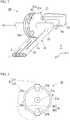
- a manufacturing apparatus 20 of the intermittently-fixed optical fiber ribbon 10 includes a plurality of rotary blades 21 disposed side by side in the width direction Y, a rotary shaft 22, and a delivery device 23.
- the plurality of rotary blades 21 are attached to the rotary shaft 22, and rotate integrally with the rotary shaft 22 around the central axis O of the rotary shaft 22.
- the rotary blade 21 is provided with a cutout portion 21b to be described later. Further, the phases (angles) in which the adjacent rotary blades 21 are attached to the rotary shaft 22 are different from each other.
- the connecting portions 2a of the intermittently-fixed optical fiber ribbon 10 are disposed in a staggered manner (zigzag manner) with respect to the longitudinal direction X and the width direction Y.
- the delivery device 23 delivers the plurality of optical fibers 1 which are collectively coated toward the rotary blade 21 at the delivery velocity V1.
- the rotary blade 21 is formed into a disc shape with the central axis O as a center.
- the rotary blade 21 has a cutout portion 21b recessed radially inward from the outer peripheral edge (radially outer edge) 21a.
- the outer peripheral edge 21a and its radially inner portion are a blade body portion 21c which forms the separating portion 2b by cutting the coating material 2.
- the cutout portion 21b is a portion forming the connecting portion 2a.
- a pair of cutout portions 21b are formed so as to interpose the central axis O therebetween in the radial direction.
- the rotary blade 21 is provided with two blade body portions 21c.
- the number, sizes, and the like of the cutout portions 21b provided in the rotary blade 21 can be appropriately changed.
- one or three or more cutout portions 21b may be provided in the rotary blade 21.
- the dimensions n1, n2, b1, b2 may be appropriately changed.
- the intermittently-fixed optical fiber ribbon 10 In manufacturing the intermittently-fixed optical fiber ribbon 10, first, in a state where a plurality of optical fibers 1 are arranged in the width direction Y, an uncured coating material 2 is applied so as to intrude between the optical fibers 1 by a coating device (not shown) and the coating material 2 is cured. Thereby, the plurality of optical fibers 1 are collectively coated with the coating material 2.
- the plurality of optical fibers 1 which are collectively coated are delivered by the delivery device 23 toward the rotary blade 21 at the delivery velocity V1.
- the rotary blade 21 is rotated around the central axis O such that the peripheral velocity at the outer peripheral edge 21a becomes V2.
- the rotary blade 21 rotates in a direction in which the moving direction of the blade body portion 21c coincides with the delivering direction by the delivery device 23. That is, when the coating material 2 is cut, the relative velocity of the outer peripheral edge 21a of the rotary blade 21 with respect to the coating material 2 and the plurality of optical fibers 1 is the difference between the peripheral velocity V2 and the delivery velocity V1.
- the coating material 2 positioned between the optical fibers 1 is cut by the blade body portion 21c of each rotary blade 21.
- the coating material 2 is intermittently cut at intervals in the longitudinal direction X.
- the connecting portion 2a and the separating portion 2b of the coating material 2 are formed.
- the method for manufacturing the intermittently-fixed optical fiber ribbon 10 in the present embodiment includes a step of collectively coating a plurality of optical fibers 1 with the coating material 2 by applying uncured coating material to intrude between the plurality of optical fibers 1 and curing the intruded uncured coating material; and a step of cutting the coating material 2 positioned between the plurality of optical fibers 1 at a predetermined interval in a longitudinal direction X, by using a plurality of rotary blades 21 disposed side by side in a width direction Y orthogonal to the longitudinal direction X, while delivering the collectively-coated optical fibers 1 at a velocity V1 in the longitudinal direction X.
- the delivery velocity V1 when the optical fibers 1 are delivered to the rotary blade 21 is changed.
- the peripheral velocity V2 is fixed.
- the intermittently-fixed optical fiber ribbon 10 of Example 1 is produced in which the connecting portions 2a are formed by partially cutting the coating material 2 with the rotary blades 21.
- Example 1 a colored optical fiber core having a diameter of ⁇ 250 ⁇ m is used as the optical fiber 1.
- the number of optical fibers 1 included in the intermittently-fixed optical fiber ribbon 10 is 12.
- the delivery velocity V1 of the optical fiber 1 which is collectively coated is varied in the range of 200 to 1200 (m/min).
- the intermittently-fixed optical fiber ribbon 10 of Comparative Example 1 is produced in which a plurality of optical fibers 1 are intermittently coated with an uncured resin, and the connecting portion 2a is formed by curing the uncured resin.
- Example 1 and Comparative Example 1 a plurality of intermittently-fixed optical fiber ribbons 10 are produced by changing the delivery velocity V1, and the results of checking the state of the connecting portion 2a are shown in the following Table 1.
- OK good
- NG defective
- OK good
- the manufacturing method for Example 1 As described above, according to the manufacturing method for Example 1, as compared with the case where uncured resin is intermittently applied to the plurality of optical fibers 1 in the longitudinal direction X and the resin is cured, and the uncured resin adheres beyond a predetermined range, it is possible to prevent the formation range of the connecting portion 2a from becoming unstable. Further, in the manufacturing method for Example 1, even if the delivery velocity V1 is increased, the forming range of the connecting portion 2a can be stabilized, so it has been confirmed that the manufacturing efficiency of the intermittently-fixed optical fiber ribbon 10 can be improved.
- the ratio between the delivery velocity V1 and the peripheral velocity V2 of the rotary blade 21 is considered.
- colored optical fiber cores of ⁇ 250 ⁇ m are used as the optical fibers 1, and after 12 optical fibers are collectively coated, the coating material 2 is partially cut by the rotary blades 21 to form the connecting portion 2a.
- the ratio between the delivery velocity V1 and the peripheral velocity V2 is changed.
- the lengths of the connecting portion 2a and the separating portion 2b in the longitudinal direction X change. Therefore, in the present example, as the ratio between the delivery velocity V1 and the peripheral velocity V2 is changed, by adjusting the number of cutout portions 21b provided in the rotary blade 21, the lengths of the connecting portion 2a and the separating portion 2b are maintained constant.
- the rotary blades 21 having eight cutout portions 21b are used.
- V1:V2 4:1
- the rotary blades 21 having four cutout portions 21b are used, as the ratio of V1 to V2 increases.
- all of the rotary blade 21 has point-symmetric shape about the central axis O.
- the intermittently-fixed optical fiber ribbon 10 (hereinafter referred to as Example 2) is produced by changing V1:V2 in a range of 1:2 to 10:1. Further, in order to compare with the intermittently-fixed optical fiber ribbon 10, a flat 12-core optical fiber ribbon without the separating portion 2b (hereinafter referred to as Comparative Example 2) is produced. Then, the optical fiber ribbon of Example 2 and Comparative Example 2 are wound around a bobbin having a barrel diameter of 310 mm at a tension of 300 gf for 10 km, and the transmission loss of light at a wavelength of 1.55 ⁇ m is measured by optical time domain reflectometer (OTDR). Then, the difference between the maximum transmission loss of light of Example 2 and the maximum transmission loss of light of Comparative Example 2 (hereinafter simply referred to as difference ⁇ ) is calculated.
- OTDR optical time domain reflectometer
- burrs are generated, when the intermittently-fixed optical fiber ribbon 10 is wound around a bobbin, the burrs are pushed against the optical fiber 1 and a local side pressure acts on the optical fiber 1, so it is thought that the transmission loss of light is increased.
- a preferable shape of the rotary blade 21 is considered.
- a plurality of types of rotary blades 21 in which the ratios of b1 and n1 shown in FIG. 3 are changed are prepared, and the intermittently-fixed optical fiber ribbon 10 is produced by using the rotary blades 21.
- the positions and the number of the cutout portions 21b in these rotary blades 21 are the same as those shown in FIG. 3 . That is, a rotary blade 21 having a pair of cutouts 21b at positions opposed to each other in the radial direction across the central axis O is used.
- the ratio between n1 and b1 (that is, the ratio between the connecting portion length N and the cutting portion length B) is varied in the range of 3:1 to 1:25.
- colored optical fiber cores of ⁇ 250 ⁇ m are used as the optical fibers 1, and after 12 optical fibers are collectively coated, the coating material 2 is partially cut by the above-described plurality types of rotary blades 21 to form the connecting portion 2a.
- the optical fiber cable 100 includes a sheath 55 made of polyethylene, a pair of tension members 56 buried in the sheath 55, twelve intermittently-fixed optical fiber ribbons 10 (Example 3) or 144 single-core colored optical fiber element wire (Comparative Example 3) accommodated in the sheath 55.
- the transmission loss of light is measured using OTDR and the difference ⁇ , of the maximum transmission loss of light is calculated.
- the evaluation result of the maximum transmission loss of light is NG (defective).
- NG defective
- the connecting portion length N is relatively large, the connecting portion 2a becomes longer in the longitudinal direction X, and the optical fibers 1 on the intermittently-fixed optical fiber ribbon 10 are less likely to move relative to each other. That is, the optical fibers 1 are installed in the optical fiber cable 100 in high density, in a state where the optical fibers 1 hardly move relative to each other, and as a result, micro-bending occurs in the optical fiber 1 or local side pressure acts, so it is considered that the transmission loss of light increases.
- Example 3 in addition to the above consideration, the workability in fusion splicing (hereinafter referred to as fusion splicing property) of the intermittently-fixed optical fiber ribbon 10 is also checked.
- fusion splicing property the workability in fusion splicing (hereinafter referred to as fusion splicing property) of the intermittently-fixed optical fiber ribbon 10 is also checked.
- N:B 1:25
- the evaluation result of the fusion splicing property is NG (defective). This is because the cutout portion length B is excessively large, so the connecting portion 2a is excessively short in the longitudinal direction X, resulting in poor integration of the optical fibers 1.
- Example 3 Similar results are obtained even when the number of cutout portions 21b in the rotary blade 21 is changed. Specifically, the same results as described above are obtained even if the rotary blade 21 provided with one, four, five, and eight cutout portions 21b are used.
- the shape of the illustrated rotary blade 21 is an example and may be changed as appropriate.
- the number of the optical fibers 1 included in the intermittently-fixed optical fiber ribbon 10 is not limited to the example shown and may be changed as appropriate. Further, as the optical fibers 1 included in the intermittently-fixed optical fiber ribbon 10 are changed, the number of the rotary blades 21 arranged in the width direction Y may be appropriately changed.
- the number (for example, three) of the rotary blades 21 is the less than the number of optical fibers 1 (for example, four) by one.
- the present invention is not limited to this, and the rotary blade 21 may not be disposed between some of the optical fibers 1.
- a plurality of optical fibers 1 arranged in the width direction Y may be an optical fiber set, and the rotary blade 21 may be disposed between the optical fiber sets.
- the number of rotary blades 21 may be one less than the number of optical fiber groups.
- one optical fiber group may include two optical fibers 1.
Landscapes
- Physics & Mathematics (AREA)
- General Physics & Mathematics (AREA)
- Optics & Photonics (AREA)
- Engineering & Computer Science (AREA)
- Manufacturing & Machinery (AREA)
- Optical Fibers, Optical Fiber Cores, And Optical Fiber Bundles (AREA)
- Light Guides In General And Applications Therefor (AREA)
- Mechanical Coupling Of Light Guides (AREA)
Abstract
Description
- The present invention relates to a method for manufacturing an intermittently-fixed optical fiber ribbon.
- Priority is claimed on Japanese Patent Application No.
2016-254763, filed on December 28, 2016 - In recent years, an intermittently-fixed-type optical fiber ribbon (hereinafter simply referred to as an intermittently-fixed optical fiber ribbon) has been proposed in which connecting portions for connecting adjacent optical fibers are intermittently disposed in the longitudinal direction of the optical fiber. The intermittently-fixed optical fiber ribbon has an advantage that optical fibers can be installed in an optical fiber cable at high density and the optical fibers can be easily and collectively fusion-spliced at the time of connection work. A method for manufacturing this type of intermittently-fixed optical fiber ribbon is disclosed in, for example,
Patent Document 1 below. - In the manufacturing method of
Patent Document 1, when delivering a plurality of optical fibers, an uncured UV curable resin serving as a connecting portion is intermittently applied to the optical fibers in the longitudinal direction. Then, the connecting portion is formed by applying UV light of an amount required for curing the UV curable resin until the optical fibers are converged in parallel. - [Patent Document 1] Japanese Unexamined Patent Application, First Publication No.
2010-33010 - Incidentally, in the manufacturing method of
Patent Document 1, an uncured UV curable resin serving as a connecting portion is intermittently applied and cured. In this case, the uncured UV curable resin may adhere to the optical fibers beyond a predetermined range, and then it is cured, there is a possibility that the interval between the connecting portions may decrease unexpectedly. Further, since the connecting portion is formed beyond the predetermined range, it is difficult for the optical fibers accommodated in the cable to move relative to each other, for example, micro-bending occurs or side pressure acts on the optical fiber, so there is a possibility that transmission loss of light increases. - The phenomenon that the formation range of the connecting portion becomes unstable as described above is especially remarkable when the delivery velocity of the optical fibers at the time of manufacturing the intermittently-fixed optical fiber ribbon is increased. Therefore, it becomes a problem in improving the manufacturing efficiency.
- The present invention has been made in consideration of such circumstances, and an object thereof is to stabilize the range in which the connecting portion is formed, and to improve manufacturing efficiency of the intermittently-fixed optical fiber ribbon.
- In order to solve the above problems, a method for manufacturing an intermittently-fixed optical fiber ribbon according to a first aspect of the present invention includes a step of collectively coating a plurality of optical fibers with a coating material by applying an uncured coating material to intrude between the plurality of optical fibers and curing the intruded uncured coating material; and a step of cutting the coating material positioned between the plurality of optical fibers at a predetermined interval in a longitudinal direction, by using a plurality of rotary blades disposed side by side in a width direction orthogonal to the longitudinal direction, while delivering the collectively-coated optical fibers at a velocity V1 in the longitudinal direction, in which the velocity V1 is greater than a peripheral velocity V2 of the rotary blade.
- According to the above aspect of the present invention, it is possible to stabilize the range in which the connecting portion is formed, and to improve manufacturing efficiency of the intermittently-fixed optical fiber ribbon.
-
-
FIG. 1 is an explanatory diagram of an intermittently-fixed optical fiber ribbon. -
FIG. 2 is a diagram showing a method for manufacturing the intermittently-fixed optical fiber ribbon ofFIG. 1 . -
FIG. 3 is an explanatory diagram of a rotary blade ofFIG. 2 . -
FIG. 4 is an explanatory diagram of an optical fiber cable using the intermittently-fixed optical fiber ribbon. - Hereinafter, an intermittently-fixed optical fiber ribbon according to the present embodiment and a manufacturing method thereof will be described with reference to
FIGS. 1 to 4 . In each drawing used in the following description, the scale is appropriately changed in order to make each member recognizable. Further, for the sake of simplicity of illustration, the number of optical fibers and the like may be changed in some cases. - As shown in
FIG. 1 , a plurality of optical fiber element wires or optical fiber core wires (hereinafter simply referred to as optical fibers 1) are collectively coated with thecoating material 2 in the intermittently-fixedoptical fiber ribbon 10. - Here, in the present embodiment, the positional relationship of each configuration will be described by setting the XYZ orthogonal coordinate system. A longitudinal direction X is a direction in which the
optical fiber 1 extends. The width direction Y is a direction in which a plurality ofoptical fibers 1 are arranged, and is orthogonal to the longitudinal direction X. The vertical direction Z is a direction orthogonal to the longitudinal direction X and the width direction Y. - The
coating material 2 is made of, for example, a UV curable resin or a thermosetting resin. Thecoating material 2 intrudes between the adjacentoptical fibers 1. A portion of thecoating material 2 located between the adjacentoptical fibers 1 is intermittently cut along the longitudinal direction X in which theoptical fiber 1 extends. Thus, a connectingportion 2a connecting the adjacentoptical fibers 1 to each other and a separatingportion 2b positioned between the connectingportions 2a adjacent to each other in the longitudinal direction X are formed. In the separatingsection 2b, the adjacentoptical fibers 1 are not connected to each other. - Another connecting
portion 2a connecting one of the adjacentoptical fibers 1 and the otheroptical fiber 1 adjacent thereto is disposed in a position shifted from the position of the connectingportion 2a connecting adjacentoptical fibers 1 in the longitudinal direction X. In this manner, the connectingportions 2a are disposed in a staggered manner (zigzag shape) with respect to both directions of the longitudinal direction X and the width direction Y. - Next, a method for manufacturing the intermittently-fixed
optical fiber ribbon 10 in the present embodiment will be described. - As shown in
FIG. 2 , amanufacturing apparatus 20 of the intermittently-fixedoptical fiber ribbon 10 includes a plurality ofrotary blades 21 disposed side by side in the width direction Y, arotary shaft 22, and adelivery device 23. The plurality ofrotary blades 21 are attached to therotary shaft 22, and rotate integrally with therotary shaft 22 around the central axis O of therotary shaft 22. Therotary blade 21 is provided with acutout portion 21b to be described later. Further, the phases (angles) in which the adjacentrotary blades 21 are attached to therotary shaft 22 are different from each other. Therefore, as described above, the connectingportions 2a of the intermittently-fixedoptical fiber ribbon 10 are disposed in a staggered manner (zigzag manner) with respect to the longitudinal direction X and the width direction Y. Thedelivery device 23 delivers the plurality ofoptical fibers 1 which are collectively coated toward therotary blade 21 at the delivery velocity V1. - As shown in
FIG. 3 , therotary blade 21 is formed into a disc shape with the central axis O as a center. Therotary blade 21 has acutout portion 21b recessed radially inward from the outer peripheral edge (radially outer edge) 21a. In therotary blade 21, the outerperipheral edge 21a and its radially inner portion are ablade body portion 21c which forms the separatingportion 2b by cutting thecoating material 2. In therotary blade 21, thecutout portion 21b is a portion forming the connectingportion 2a. - In the example shown, a pair of
cutout portions 21b are formed so as to interpose the central axis O therebetween in the radial direction. Thus, therotary blade 21 is provided with twoblade body portions 21c. The arc lengths of the outerperipheral edges 21a of the twoblade body portions 21c are b1 and b2, respectively. Therefore, the total value of the arc lengths of the outerperipheral edges 21a of the rotary blades 21 (hereinafter referred to as the cut portion length B) is calculated by B = b1 + b2. - The virtual arc lengths of the outer
peripheral edges 21a in the twocutout portions 21b are n1 and n2. Therefore, the total value of the virtual arc lengths of the outerperipheral edges 21a of thecutout portions 21b of the rotary blades 21 (hereinafter referred to as the connecting portion length N) is calculated by N = n1 + n2. - In the example shown, since the
rotary blades 21 are point-symmetric shape about the central axis O, b1 and b2 are substantially equal to each other and n1 and n2 are substantially equal to each other. Therefore, all the ratio between b1 and n1, the ratio between b2 and n2, and the ratio between B and N are substantially equal. - The number, sizes, and the like of the
cutout portions 21b provided in therotary blade 21 can be appropriately changed. For example, one or three or morecutout portions 21b may be provided in therotary blade 21. Alternatively, the dimensions n1, n2, b1, b2 may be appropriately changed. - In manufacturing the intermittently-fixed
optical fiber ribbon 10, first, in a state where a plurality ofoptical fibers 1 are arranged in the width direction Y, anuncured coating material 2 is applied so as to intrude between theoptical fibers 1 by a coating device (not shown) and thecoating material 2 is cured. Thereby, the plurality ofoptical fibers 1 are collectively coated with thecoating material 2. - Next, the plurality of
optical fibers 1 which are collectively coated are delivered by thedelivery device 23 toward therotary blade 21 at the delivery velocity V1. At this time, therotary blade 21 is rotated around the central axis O such that the peripheral velocity at the outerperipheral edge 21a becomes V2. In the portion where therotary blade 21 and thecoating material 2 are in contact with each other, therotary blade 21 rotates in a direction in which the moving direction of theblade body portion 21c coincides with the delivering direction by thedelivery device 23. That is, when thecoating material 2 is cut, the relative velocity of the outerperipheral edge 21a of therotary blade 21 with respect to thecoating material 2 and the plurality ofoptical fibers 1 is the difference between the peripheral velocity V2 and the delivery velocity V1. - When the plurality of
optical fibers 1 which are collectively coated are brought into contact with the plurality ofrotary blades 21, thecoating material 2 positioned between theoptical fibers 1 is cut by theblade body portion 21c of eachrotary blade 21. At this time, since thecoating material 2 is not cut at thecutout portion 21b, thecoating material 2 is intermittently cut at intervals in the longitudinal direction X. Thus, the connectingportion 2a and the separatingportion 2b of thecoating material 2 are formed. - As described above, the method for manufacturing the intermittently-fixed
optical fiber ribbon 10 in the present embodiment includes a step of collectively coating a plurality ofoptical fibers 1 with thecoating material 2 by applying uncured coating material to intrude between the plurality ofoptical fibers 1 and curing the intruded uncured coating material; and a step of cutting thecoating material 2 positioned between the plurality ofoptical fibers 1 at a predetermined interval in a longitudinal direction X, by using a plurality ofrotary blades 21 disposed side by side in a width direction Y orthogonal to the longitudinal direction X, while delivering the collectively-coatedoptical fibers 1 at a velocity V1 in the longitudinal direction X. - Next, specific examples of the above manufacturing method will be described.
- In this example, it is considered to check the superiority of the above manufacturing method.
- Specifically, as described above, after the
optical fibers 1 are collectively coated, the delivery velocity V1 when theoptical fibers 1 are delivered to therotary blade 21 is changed. The peripheral velocity V2 is fixed. Then, the intermittently-fixedoptical fiber ribbon 10 of Example 1 is produced in which the connectingportions 2a are formed by partially cutting thecoating material 2 with therotary blades 21. - In Example 1, a colored optical fiber core having a diameter of ϕ250 µm is used as the
optical fiber 1. The number ofoptical fibers 1 included in the intermittently-fixedoptical fiber ribbon 10 is 12. The delivery velocity V1 of theoptical fiber 1 which is collectively coated is varied in the range of 200 to 1200 (m/min). - Further, in order to compare with Example 1, as in the related art, the intermittently-fixed
optical fiber ribbon 10 of Comparative Example 1 is produced in which a plurality ofoptical fibers 1 are intermittently coated with an uncured resin, and the connectingportion 2a is formed by curing the uncured resin. - With respect to Example 1 and Comparative Example 1, a plurality of intermittently-fixed
optical fiber ribbons 10 are produced by changing the delivery velocity V1, and the results of checking the state of the connectingportion 2a are shown in the following Table 1. In Table 1, OK (good) is indicated as acceptable or good determination, and NG (defective) is indicated as rejection or failure determination. Specifically, the case where the connectingportion 2a is formed beyond the desired range is defined as NG (defective), and the case where the connectingportion 2a is formed within the desired range is defined as OK (good).[Table 1] Delivery Velocity V1 (m/min) 200 400 600 800 1000 1200 Comparative Example 1 OK OK OK OK NG NG Example 1 OK OK OK OK OK OK - As shown in Table 1, when the delivery velocity V1 is 1000 (m/min) or more, in Comparative Example 1, the connecting
portion 2a is formed beyond the desired range. On the other hand, in the manufacturing method for Example 1, even when the delivery velocity V1 is 1000 (m/min) or more, the connectingportion 2a is formed within the desired range. - As described above, according to the manufacturing method for Example 1, as compared with the case where uncured resin is intermittently applied to the plurality of
optical fibers 1 in the longitudinal direction X and the resin is cured, and the uncured resin adheres beyond a predetermined range, it is possible to prevent the formation range of the connectingportion 2a from becoming unstable. Further, in the manufacturing method for Example 1, even if the delivery velocity V1 is increased, the forming range of the connectingportion 2a can be stabilized, so it has been confirmed that the manufacturing efficiency of the intermittently-fixedoptical fiber ribbon 10 can be improved. - In the present example, the ratio between the delivery velocity V1 and the peripheral velocity V2 of the
rotary blade 21 is considered. - Specifically, colored optical fiber cores of ϕ250 µm are used as the
optical fibers 1, and after 12 optical fibers are collectively coated, thecoating material 2 is partially cut by therotary blades 21 to form the connectingportion 2a. At this time, the ratio between the delivery velocity V1 and the peripheral velocity V2 is changed. When this ratio is changed, if thesame rotary blade 21 is used, the lengths of the connectingportion 2a and the separatingportion 2b in the longitudinal direction X change. Therefore, in the present example, as the ratio between the delivery velocity V1 and the peripheral velocity V2 is changed, by adjusting the number ofcutout portions 21b provided in therotary blade 21, the lengths of the connectingportion 2a and the separatingportion 2b are maintained constant. For example, when V1:V2 = 4:1, therotary blades 21 having eightcutout portions 21b are used. With this as a reference, for example, when V1:V2 = 2:1, therotary blades 21 having fourcutout portions 21b are used, as the ratio of V1 to V2 increases. Here, in the present example, all of therotary blade 21 has point-symmetric shape about the central axis O. - In the present example, the intermittently-fixed optical fiber ribbon 10 (hereinafter referred to as Example 2) is produced by changing V1:V2 in a range of 1:2 to 10:1. Further, in order to compare with the intermittently-fixed
optical fiber ribbon 10, a flat 12-core optical fiber ribbon without the separatingportion 2b (hereinafter referred to as Comparative Example 2) is produced. Then, the optical fiber ribbon of Example 2 and Comparative Example 2 are wound around a bobbin having a barrel diameter of 310 mm at a tension of 300 gf for 10 km, and the transmission loss of light at a wavelength of 1.55 µm is measured by optical time domain reflectometer (OTDR). Then, the difference between the maximum transmission loss of light of Example 2 and the maximum transmission loss of light of Comparative Example 2 (hereinafter simply referred to as difference Δα) is calculated. - In the following Table 2, it is assumed that the evaluation result is OK (good) as being good when Δα ≤ 0.05 (dB/km), and the evaluation result is NG (defective) as being insufficient when Δα > 0.05 (dB/km).
[Table 2] Velocity Ratio (V1:V2) 1:2 1:1 3:2 2:1 3:1 4:1 6:1 8:1 10:1 Transmission Loss Δα (dB/km) 0.08 0.07 0.07 0.03 0.03 0.02 0.04 0.02 0.03 Determination NG NG NG OK OK OK OK OK OK - From Table 2, it can be determined that when the peripheral velocity V2 of the
rotary blade 21 is relatively large, the transmission loss of light of the intermittently-fixedoptical fiber ribbon 10 tends to increase. Specifically, the evaluation result is NG (bad) when V1:V2 is in the range of 1:2 to 3:2. This is thought to be because when the peripheral velocity V2 of therotary blade 21 is relatively large, thecoating material 2 is cut such that therotary blade 21 presses against thecoating material 2 mainly from the vertical direction Z, so burrs protruding in the vertical direction Z are likely to occur. In a case where such burrs are generated, when the intermittently-fixedoptical fiber ribbon 10 is wound around a bobbin, the burrs are pushed against theoptical fiber 1 and a local side pressure acts on theoptical fiber 1, so it is thought that the transmission loss of light is increased. - On the other hand, when V1:V2 is in the range of 2:1 to 10:1, the evaluation result is OK (good). When the peripheral velocity V2 of the
rotary blade 21 is relatively small, thecoating material 2 is cut such that therotary blade 21 presses against thecoating material 2 mainly from the longitudinal direction X. Therefore, burrs protruding in the vertical direction Z are less likely to occur. In the case where such burrs are unlikely to occur, since the local side pressure caused by the burrs pressing against theoptical fiber 1 hardly acts on theoptical fiber 1, it is possible to suppress the transmission loss of light to the same amount as in the flat optical fiber ribbon of the Comparative Example 2, which does not have the separatingportion 2b. - According to the above results, it is possible to suppress occurrence of burrs when cutting the
coating material 2 by setting the delivery velocity V1 to be twice or more the peripheral velocity V2 of therotary blade 21. Further, it is possible to suppress an increase in the transmission loss of light, the transmission loss caused by the burr when the intermittently-fixedoptical fiber ribbon 10 is wound around the bobbin and a side pressure acts on theoptical fiber 1 by the burr. Further, it is considered that such an effect can be obtained also when, for example, the intermittently-fixedoptical fiber ribbons 10 are bundled at high density in the optical fiber cable. - In the present example, a preferable shape of the
rotary blade 21 is considered. - Specifically, a plurality of types of
rotary blades 21 in which the ratios of b1 and n1 shown inFIG. 3 are changed are prepared, and the intermittently-fixedoptical fiber ribbon 10 is produced by using therotary blades 21. The positions and the number of thecutout portions 21b in theserotary blades 21 are the same as those shown inFIG. 3 . That is, arotary blade 21 having a pair ofcutouts 21b at positions opposed to each other in the radial direction across the central axis O is used. Therotary blades 21 are point-symmetric shape about the central axis O. Therefore, n1 = n2 and b1 = b2 is satisfied. Further, n1:b1 = n2:b2 = N:B is satisfied. The ratio between n1 and b1 (that is, the ratio between the connecting portion length N and the cutting portion length B) is varied in the range of 3:1 to 1:25. - In this embodiment, colored optical fiber cores of ϕ250 µm are used as the
optical fibers 1, and after 12 optical fibers are collectively coated, thecoating material 2 is partially cut by the above-described plurality types ofrotary blades 21 to form the connectingportion 2a. - Further, using the intermittently-fixed
optical fiber ribbons 10 of Example 3 and the single-core colored optical fiber element wire (Comparative Example 3), a 144-coreoptical fiber cable 100 as shown inFIG. 4 is produced. Theoptical fiber cable 100 includes asheath 55 made of polyethylene, a pair oftension members 56 buried in thesheath 55, twelve intermittently-fixed optical fiber ribbons 10 (Example 3) or 144 single-core colored optical fiber element wire (Comparative Example 3) accommodated in thesheath 55. - With respect to the
optical fiber cable 100 using the intermittently-fixedoptical fiber ribbon 10 of Example 3 and theoptical fiber cable 100 using the single-core colored optical fiber element wire of Comparative Example 3, the transmission loss of light is measured using OTDR and the difference Δα, of the maximum transmission loss of light is calculated. - In the following Table 3, it is assumed that the evaluation result is OK (good) as being good when Δα ≤ 0.05 (dB/km), and the evaluation result is NG (defective) as being insufficient when Δα > 0.05 (dB/km).
[Table 3] Connecting Portion Length N:Cutout Portion Length B 3:1 2:1 1:1 1:2 1:3 1:5 1:7 1:10 1:15 1:20 1:25 Maximum Transmission Loss (dB/km) Δα (dB/km) 0.1 0.08 0.04 0.04 0.03 0.04 0.02 0.03 0.01 0.03 0.01 Determination NG NG OK OK OK OK OK OK OK OK OK Fusion Splicing Property OK OK OK OK OK OK OK OK OK OK NG - As shown in Table 3, when the connecting portion length N is twice or more the cutout portion length B, the evaluation result of the maximum transmission loss of light is NG (defective). This is thought to be because when the connecting portion length N is relatively large, the connecting
portion 2a becomes longer in the longitudinal direction X, and theoptical fibers 1 on the intermittently-fixedoptical fiber ribbon 10 are less likely to move relative to each other. That is, theoptical fibers 1 are installed in theoptical fiber cable 100 in high density, in a state where theoptical fibers 1 hardly move relative to each other, and
as a result, micro-bending occurs in theoptical fiber 1 or local side pressure acts, so it is considered that the transmission loss of light increases. - On the other hand, as shown in Table 3, when the cutout portion length B is equal to or larger than the connecting portion length N, that is, B ≥ N, the evaluation result of the maximum transmission loss of light is OK (good). This is thought to be because the proportion of the
blade body portion 21c cutting thecoating material 2 occupied in therotary blade 21 is larger than that of thecutout portion 21b, so the connectingportion 2a formed is shortened in the longitudinal direction X. That is, since the connectingportion 2a is short, theoptical fibers 1 are easily moved relative to each other, and even if theoptical fibers 1 are installed at a high density in theoptical fiber cable 100, theoptical fibers 1 are likely to enter the empty space in thesheath 55. Thus, the generation of micro-bending in theoptical fiber 1 or the action of local side pressure is suppressed, and as a result, it could be considered that the increase in the transmission loss of light could be suppressed. - Further, in Example 3, in addition to the above consideration, the workability in fusion splicing (hereinafter referred to as fusion splicing property) of the intermittently-fixed
optical fiber ribbon 10 is also checked. As shown in Table 3, when N:B is 1:25, the evaluation result of the fusion splicing property is NG (defective). This is because the cutout portion length B is excessively large, so the connectingportion 2a is excessively short in the longitudinal direction X, resulting in poor integration of theoptical fibers 1. - On the other hand, in the case of B ≤ 20N, it is possible to prevent the fusion splicing property from deteriorating as a result of securing the length of the connecting
portion 2a in the longitudinal direction X. - From the above, by setting N ≤ B ≤ 20N, the length of the connecting
portion 2a in the longitudinal direction X falls within a preferable range, and it is possible to secure the fusion splicing property while suppressing an increase in the transmission loss of light. - In the above consideration in Example 3, similar results are obtained even when the number of
cutout portions 21b in therotary blade 21 is changed. Specifically, the same results as described above are obtained even if therotary blade 21 provided with one, four, five, and eightcutout portions 21b are used. - It should be noted that the technical scope of the present invention is not limited to the above-described embodiments, and various modifications can be made without departing from the spirit of the present invention.
- For example, the shape of the illustrated
rotary blade 21 is an example and may be changed as appropriate. - The number of the
optical fibers 1 included in the intermittently-fixedoptical fiber ribbon 10 is not limited to the example shown and may be changed as appropriate. Further, as theoptical fibers 1 included in the intermittently-fixedoptical fiber ribbon 10 are changed, the number of therotary blades 21 arranged in the width direction Y may be appropriately changed. - In
FIGS. 1 and2 , since therotary blades 21 are disposed all the spaces between the adjacentoptical fibers 1, the number (for example, three) of therotary blades 21 is the less than the number of optical fibers 1 (for example, four) by one. However, the present invention is not limited to this, and therotary blade 21 may not be disposed between some of theoptical fibers 1. For example, a plurality ofoptical fibers 1 arranged in the width direction Y may be an optical fiber set, and therotary blade 21 may be disposed between the optical fiber sets. In this case, the number ofrotary blades 21 may be one less than the number of optical fiber groups. In addition, one optical fiber group may include twooptical fibers 1. - Besides, without departing from the spirit of the present invention, it is possible to appropriately replace the constituent elements in the above-described embodiment with well-known constituent elements, and the above-described embodiment and modifications may be appropriately combined.
-
- 1
- OPTICAL FIBER
- 2
- COATING MATERIAL
- 2a
- CONNECTING PORTION
- 10
- INTERMITTENTLY-FIXED OPTICAL FIBER RIBBON
- 21
- ROTARY BLADE
- 21a
- OUTER PERIPHERAL EDGE
- 21b
- CUTOUT PORTION
- B
- CUTOUT PORTION LENGTH
- N
- CONNECTING PORTION LENGTH
- V1
- VELOCITY
- V2
- PERIPHERAL VELOCITY
Claims (4)
- A method for manufacturing an intermittently-fixed optical fiber ribbon, the method comprising:a step of collectively coating a plurality of optical fibers with a coating material by applying an uncured coating material to intrude between the plurality of optical fibers and curing the intruded uncured coating material; anda step of cutting the coating material positioned between the plurality of optical fibers at a predetermined interval in a longitudinal direction, by using a plurality of rotary blades disposed side by side in a width direction orthogonal to the longitudinal direction, while delivering the collectively-coated optical fibers at a velocity V1 in the longitudinal direction,wherein the velocity V1 is greater than a peripheral velocity V2 of the rotary blade.
- The method for manufacturing an intermittently-fixed optical fiber ribbon according to claim 1,
wherein the velocity V1 is at least twice the peripheral velocity V2. - The method for manufacturing an intermittently-fixed optical fiber ribbon according to claim 1 or 2,
wherein the rotary blade is formed in a disc shape and has cutout portions recessed radially inward from outer peripheral edges, and
wherein when B is a sum of arc lengths of the outer peripheral edges and N is a sum of virtual arc lengths of the outer peripheral edges in the cutout portion, B ≥ N is satisfied. - The method for manufacturing an intermittently-fixed optical fiber ribbon according to claim 3,
wherein B ≤ 20N is satisfied.
Applications Claiming Priority (2)
| Application Number | Priority Date | Filing Date | Title |
|---|---|---|---|
| JP2016254763A JP2018106098A (en) | 2016-12-28 | 2016-12-28 | Method of manufacturing intermittently fixed optical fiber ribbon |
| PCT/JP2017/046146 WO2018123871A1 (en) | 2016-12-28 | 2017-12-22 | Method for manufacturing intermittently-fixed tape core |
Publications (2)
| Publication Number | Publication Date |
|---|---|
| EP3564722A1 true EP3564722A1 (en) | 2019-11-06 |
| EP3564722A4 EP3564722A4 (en) | 2020-08-05 |
Family
ID=62707693
Family Applications (1)
| Application Number | Title | Priority Date | Filing Date |
|---|---|---|---|
| EP17888374.0A Withdrawn EP3564722A4 (en) | 2016-12-28 | 2017-12-22 | METHOD OF MANUFACTURING INTERMITTING FIXED TAPE CORE |
Country Status (9)
| Country | Link |
|---|---|
| US (1) | US10705304B2 (en) |
| EP (1) | EP3564722A4 (en) |
| JP (1) | JP2018106098A (en) |
| KR (1) | KR20190064646A (en) |
| CN (1) | CN110023807A (en) |
| AU (1) | AU2017386623B2 (en) |
| CA (1) | CA3045421A1 (en) |
| TW (1) | TWI683146B (en) |
| WO (1) | WO2018123871A1 (en) |
Families Citing this family (6)
| Publication number | Priority date | Publication date | Assignee | Title |
|---|---|---|---|---|
| JP2018106098A (en) * | 2016-12-28 | 2018-07-05 | 株式会社フジクラ | Method of manufacturing intermittently fixed optical fiber ribbon |
| CN116324556A (en) | 2020-08-31 | 2023-06-23 | 康宁研究与开发公司 | Intermittently bonded belt having intermittent bonds produced with a wet-on-wet process |
| JPWO2022065485A1 (en) * | 2020-09-28 | 2022-03-31 | ||
| WO2022086700A1 (en) | 2020-10-19 | 2022-04-28 | Corning Research & Development Corporation | Ribbon with non-overlapping intermittent bonds between optical fiber subunits |
| CN115755294A (en) * | 2022-10-24 | 2023-03-07 | 长飞光纤光缆股份有限公司 | Self-supporting optical cable and manufacturing method |
| JP7732129B1 (en) * | 2024-02-21 | 2025-09-01 | Swcc株式会社 | Optical fiber ribbon manufacturing method and optical fiber ribbon manufacturing device |
Family Cites Families (15)
| Publication number | Priority date | Publication date | Assignee | Title |
|---|---|---|---|---|
| US6584257B1 (en) * | 2000-12-27 | 2003-06-24 | Corning Cable Systems, Llc | Fiber optic assembly and method of making same |
| JP4055000B2 (en) * | 2003-08-11 | 2008-03-05 | 住友電気工業株式会社 | Optical fiber cable, optical fiber cable manufacturing method, and optical fiber cable manufacturing apparatus |
| JP5149230B2 (en) | 2008-06-23 | 2013-02-20 | 株式会社フジクラ | Manufacturing method and manufacturing apparatus for optical fiber ribbon |
| JP5200093B2 (en) * | 2010-11-18 | 2013-05-15 | 株式会社フジクラ | Optical fiber tape core manufacturing method, manufacturing apparatus, and optical fiber tape core and optical fiber cable manufactured by the manufacturing method |
| JP5309189B2 (en) | 2011-06-03 | 2013-10-09 | 株式会社フジクラ | Manufacturing method of optical fiber ribbon and optical fiber ribbon manufactured by the manufacturing method |
| JP5564026B2 (en) * | 2011-10-18 | 2014-07-30 | 株式会社フジクラ | Optical fiber tape core and optical fiber cable storing the optical fiber core |
| JP5450687B2 (en) * | 2012-02-15 | 2014-03-26 | 昭和電線ケーブルシステム株式会社 | Optical fiber ribbon manufacturing method and optical fiber ribbon manufacturing apparatus |
| JP5391296B2 (en) * | 2012-03-02 | 2014-01-15 | 株式会社フジクラ | Optical fiber tape core and optical fiber cable storing the optical fiber core |
| JP6015152B2 (en) * | 2012-06-12 | 2016-10-26 | 住友電気工業株式会社 | Apparatus and method for manufacturing intermittently cut optical fiber ribbon |
| JP2014133372A (en) * | 2013-01-11 | 2014-07-24 | Fujikura Ltd | Printer, printing method, optical fiber and optical fiber cable |
| JP5852045B2 (en) * | 2013-05-07 | 2016-02-03 | 株式会社フジクラ | Optical fiber ribbon and optical fiber cable |
| JP2015215448A (en) * | 2014-05-09 | 2015-12-03 | 株式会社フジクラ | Fiber optic cable |
| JP2016206499A (en) * | 2015-04-24 | 2016-12-08 | 住友電気工業株式会社 | Manufacturing apparatus and manufacturing method of intermittent optical fiber ribbon |
| AU2016386157A1 (en) * | 2016-01-13 | 2018-07-19 | Sumitomo Electric Industries, Ltd. | Intermittent-connection-type optical fiber tape core, optical cable, and method for manufacturing intermittent-connection-type optical fiber tape core |
| JP2018106098A (en) * | 2016-12-28 | 2018-07-05 | 株式会社フジクラ | Method of manufacturing intermittently fixed optical fiber ribbon |
-
2016
- 2016-12-28 JP JP2016254763A patent/JP2018106098A/en active Pending
-
2017
- 2017-12-22 WO PCT/JP2017/046146 patent/WO2018123871A1/en not_active Ceased
- 2017-12-22 EP EP17888374.0A patent/EP3564722A4/en not_active Withdrawn
- 2017-12-22 CN CN201780073543.8A patent/CN110023807A/en active Pending
- 2017-12-22 US US16/462,728 patent/US10705304B2/en active Active
- 2017-12-22 KR KR1020197014102A patent/KR20190064646A/en not_active Ceased
- 2017-12-22 CA CA3045421A patent/CA3045421A1/en not_active Abandoned
- 2017-12-22 AU AU2017386623A patent/AU2017386623B2/en active Active
- 2017-12-25 TW TW106145507A patent/TWI683146B/en active
Also Published As
| Publication number | Publication date |
|---|---|
| AU2017386623B2 (en) | 2020-04-30 |
| AU2017386623A1 (en) | 2019-06-13 |
| CN110023807A (en) | 2019-07-16 |
| WO2018123871A1 (en) | 2018-07-05 |
| TW201833613A (en) | 2018-09-16 |
| CA3045421A1 (en) | 2018-07-05 |
| EP3564722A4 (en) | 2020-08-05 |
| KR20190064646A (en) | 2019-06-10 |
| US20190317289A1 (en) | 2019-10-17 |
| JP2018106098A (en) | 2018-07-05 |
| TWI683146B (en) | 2020-01-21 |
| US10705304B2 (en) | 2020-07-07 |
Similar Documents
| Publication | Publication Date | Title |
|---|---|---|
| US10705304B2 (en) | Method for manufacturing intermittently-fixed optical fiber ribbon | |
| EP3404462B1 (en) | Intermittently joined optical fiber ribbon and optical cable | |
| JP5852045B2 (en) | Optical fiber ribbon and optical fiber cable | |
| EP2770357A1 (en) | Optical fiber tape core wire and optical fiber cable housing optical fiber tape core wire | |
| KR102408811B1 (en) | Intermittent connection type optical fiber tape and manufacturing method of intermittent connection type optical fiber tape | |
| WO2022009798A1 (en) | Optical fiber tape core wire and optical fiber cable | |
| US20130058614A1 (en) | Optical fiber cables having reversal point banding and methods of making thereof | |
| EP3923052B1 (en) | An intermittently coupled-type optical fiber ribbon and a method for manufacturing thereof | |
| EP2811325A1 (en) | Multi-core optical fiber tape | |
| WO2018221142A1 (en) | Optical fiber cable and method for manufacturing optical fiber cable | |
| CA2960325A1 (en) | Optical fiber cable, and method and apparatus for manufacturing optical fiber cable | |
| US11009668B2 (en) | Optical fiber ribbon and optical fiber cable | |
| US20250189742A1 (en) | Optical fiber ribbon and slot-less optical cable | |
| EP3518013A1 (en) | Optical fiber unit and optical fiber cable | |
| EP3943992A1 (en) | Intermittent connection-type optical fiber tape core, optical fiber cable and connector-equipped optical fiber cord | |
| JP2001318286A (en) | Optical fiber cable and combined power / optical cable | |
| JP2017156558A (en) | Manufacturing method for optical fiber cable, and manufacturing method for optical fiber tape ribbon | |
| JP5947967B2 (en) | Optical fiber ribbon and optical fiber cable | |
| KR20070010148A (en) | Fiber Optic Tape Units and Fiber Optic Cables | |
| JP2018180553A (en) | Manufacturing method of intermittent fixing tape core wire | |
| JP2005321645A (en) | Tape type optical fiber | |
| CN114402244B (en) | Optical connector and method of modifying an optical connector | |
| JP3568565B2 (en) | Split optical fiber ribbon | |
| KR20000050475A (en) | Apparatus of forming ribbon optical fiber | |
| JPH06235850A (en) | Production of spacer type optical cable |
Legal Events
| Date | Code | Title | Description |
|---|---|---|---|
| STAA | Information on the status of an ep patent application or granted ep patent |
Free format text: STATUS: THE INTERNATIONAL PUBLICATION HAS BEEN MADE |
|
| PUAI | Public reference made under article 153(3) epc to a published international application that has entered the european phase |
Free format text: ORIGINAL CODE: 0009012 |
|
| STAA | Information on the status of an ep patent application or granted ep patent |
Free format text: STATUS: REQUEST FOR EXAMINATION WAS MADE |
|
| 17P | Request for examination filed |
Effective date: 20190522 |
|
| AK | Designated contracting states |
Kind code of ref document: A1 Designated state(s): AL AT BE BG CH CY CZ DE DK EE ES FI FR GB GR HR HU IE IS IT LI LT LU LV MC MK MT NL NO PL PT RO RS SE SI SK SM TR |
|
| AX | Request for extension of the european patent |
Extension state: BA ME |
|
| DAV | Request for validation of the european patent (deleted) | ||
| DAX | Request for extension of the european patent (deleted) | ||
| A4 | Supplementary search report drawn up and despatched |
Effective date: 20200707 |
|
| RIC1 | Information provided on ipc code assigned before grant |
Ipc: G02B 6/44 20060101AFI20200701BHEP |
|
| STAA | Information on the status of an ep patent application or granted ep patent |
Free format text: STATUS: EXAMINATION IS IN PROGRESS |
|
| 17Q | First examination report despatched |
Effective date: 20210621 |
|
| STAA | Information on the status of an ep patent application or granted ep patent |
Free format text: STATUS: THE APPLICATION HAS BEEN WITHDRAWN |
|
| 18W | Application withdrawn |
Effective date: 20210719 |