EP3564700A1 - Distance sensing assembly and mobile terminal - Google Patents
Distance sensing assembly and mobile terminal Download PDFInfo
- Publication number
- EP3564700A1 EP3564700A1 EP19169391.0A EP19169391A EP3564700A1 EP 3564700 A1 EP3564700 A1 EP 3564700A1 EP 19169391 A EP19169391 A EP 19169391A EP 3564700 A1 EP3564700 A1 EP 3564700A1
- Authority
- EP
- European Patent Office
- Prior art keywords
- gap
- reflective mirror
- infrared light
- sensing assembly
- light guide
- Prior art date
- Legal status (The legal status is an assumption and is not a legal conclusion. Google has not performed a legal analysis and makes no representation as to the accuracy of the status listed.)
- Granted
Links
Images


Classifications
-
- G—PHYSICS
- G01—MEASURING; TESTING
- G01S—RADIO DIRECTION-FINDING; RADIO NAVIGATION; DETERMINING DISTANCE OR VELOCITY BY USE OF RADIO WAVES; LOCATING OR PRESENCE-DETECTING BY USE OF THE REFLECTION OR RERADIATION OF RADIO WAVES; ANALOGOUS ARRANGEMENTS USING OTHER WAVES
- G01S7/00—Details of systems according to groups G01S13/00, G01S15/00, G01S17/00
- G01S7/48—Details of systems according to groups G01S13/00, G01S15/00, G01S17/00 of systems according to group G01S17/00
- G01S7/481—Constructional features, e.g. arrangements of optical elements
- G01S7/4811—Constructional features, e.g. arrangements of optical elements common to transmitter and receiver
-
- G—PHYSICS
- G01—MEASURING; TESTING
- G01S—RADIO DIRECTION-FINDING; RADIO NAVIGATION; DETERMINING DISTANCE OR VELOCITY BY USE OF RADIO WAVES; LOCATING OR PRESENCE-DETECTING BY USE OF THE REFLECTION OR RERADIATION OF RADIO WAVES; ANALOGOUS ARRANGEMENTS USING OTHER WAVES
- G01S17/00—Systems using the reflection or reradiation of electromagnetic waves other than radio waves, e.g. lidar systems
- G01S17/02—Systems using the reflection of electromagnetic waves other than radio waves
- G01S17/06—Systems determining position data of a target
- G01S17/08—Systems determining position data of a target for measuring distance only
-
- G—PHYSICS
- G01—MEASURING; TESTING
- G01S—RADIO DIRECTION-FINDING; RADIO NAVIGATION; DETERMINING DISTANCE OR VELOCITY BY USE OF RADIO WAVES; LOCATING OR PRESENCE-DETECTING BY USE OF THE REFLECTION OR RERADIATION OF RADIO WAVES; ANALOGOUS ARRANGEMENTS USING OTHER WAVES
- G01S7/00—Details of systems according to groups G01S13/00, G01S15/00, G01S17/00
- G01S7/48—Details of systems according to groups G01S13/00, G01S15/00, G01S17/00 of systems according to group G01S17/00
- G01S7/481—Constructional features, e.g. arrangements of optical elements
- G01S7/4814—Constructional features, e.g. arrangements of optical elements of transmitters alone
-
- G—PHYSICS
- G01—MEASURING; TESTING
- G01S—RADIO DIRECTION-FINDING; RADIO NAVIGATION; DETERMINING DISTANCE OR VELOCITY BY USE OF RADIO WAVES; LOCATING OR PRESENCE-DETECTING BY USE OF THE REFLECTION OR RERADIATION OF RADIO WAVES; ANALOGOUS ARRANGEMENTS USING OTHER WAVES
- G01S7/00—Details of systems according to groups G01S13/00, G01S15/00, G01S17/00
- G01S7/48—Details of systems according to groups G01S13/00, G01S15/00, G01S17/00 of systems according to group G01S17/00
- G01S7/481—Constructional features, e.g. arrangements of optical elements
- G01S7/4818—Constructional features, e.g. arrangements of optical elements using optical fibres
-
- H—ELECTRICITY
- H04—ELECTRIC COMMUNICATION TECHNIQUE
- H04M—TELEPHONIC COMMUNICATION
- H04M1/00—Substation equipment, e.g. for use by subscribers
- H04M1/02—Constructional features of telephone sets
- H04M1/0202—Portable telephone sets, e.g. cordless phones, mobile phones or bar type handsets
- H04M1/026—Details of the structure or mounting of specific components
-
- H—ELECTRICITY
- H04—ELECTRIC COMMUNICATION TECHNIQUE
- H04M—TELEPHONIC COMMUNICATION
- H04M1/00—Substation equipment, e.g. for use by subscribers
- H04M1/72—Mobile telephones; Cordless telephones, i.e. devices for establishing wireless links to base stations without route selection
- H04M1/724—User interfaces specially adapted for cordless or mobile telephones
- H04M1/72448—User interfaces specially adapted for cordless or mobile telephones with means for adapting the functionality of the device according to specific conditions
- H04M1/72454—User interfaces specially adapted for cordless or mobile telephones with means for adapting the functionality of the device according to specific conditions according to context-related or environment-related conditions
Definitions
- the present disclosure relates to the field of electronic technologies, and particularly, to a distance sensing assembly and a mobile terminal.
- an opening is formed in a region other than the display region of the mobile terminal panel, and a distance sensor is arranged below the opening.
- the distance sensor emits and receives infrared light through the opening to perform distance detection.
- the present disclosure provides a distance sensing assembly and a mobile terminal.
- a distance sensing assembly comprising: an emitter array, a receiver array and a reflective mirror, wherein the emitter array, the receiver array and the reflective mirror are located below a cover plate of a mobile terminal; an orthographic projection of the reflective mirror on a plane of the cover plate covers at least a portion of a gap between the cover plate and an earpiece of the mobile terminal; infrared light emitted by the emitter array passes, after being reflected by the reflective mirror, through the gap to be emitted; and the receiver array receives the infrared light which is reflected, after passing through the gap, by the reflective mirror.
- a distance sensing assembly comprising: an emitter array, a receiver array, a first light guide column and a second light guide column, wherein the emitter array, the receiver array, the first light guide column and the second light guide column are located below a cover plate of a mobile terminal; the first light guide column is configured to guide infrared light emitted by the emitter array toward a gap between the cover plate and an earpiece of the mobile terminal; and the second light guide column is configured to guide the infrared light passing through the gap toward the receiver array.
- a mobile terminal comprising the distance sensing assembly as described in the first or second aspects.
- a distance sensor 130 is arranged below the opening 120.
- the distance sensor 130 emits and receives infrared light through the opening 120 to perform distance detection. As the opening 120 occupies a certain area on the panel 100, the area occupied by the display region 110 on the panel 100 would be limited.
- the embodiments of the present disclosure provide a distance sensing assembly to increase the screen-to-body ratio of the mobile terminal, improve the display performance and the aesthetic effect of the mobile terminal.
- the embodiments of the present disclosure adopt two manners to change the optical path, so as to effectively avoid the influence of the infrared light emitted by the emitter array on the display performance of the display region.
- the optical path is changed by arranging a reflective mirror; and in the second manner, the optical path is changed by arranging a light guide structure, such as a light guide column.
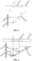
- Fig. 2 is a schematically structural view of a first distance sensing assembly according to an exemplary embodiment. This embodiment of the present disclosure is configured to explain the first manner.
- the distance sensing assembly includes an emitter array 1, a receiver array 2 and a reflective mirror 3, and all these structures are located below a cover plate 4 of a mobile terminal.
- An orthographic projection of the reflective mirror 3 on a plane of the cover plate 4 covers at least a portion of a gap 5 between the cover plate 4 and an earpiece of the mobile terminal.
- the infrared light emitted by the emitter array 1 is reflected by the reflective mirror 3, then passes through the gap 5 to be emitted out.
- the receiver array 2 receives the infrared light which is reflected, after passing through the gap 5, by the reflective mirror 3.
- the emitter array 1 and the receiver array 2 may be respectively integrated on two Integrated Circuit (IC) chips, or may be integrated on one IC chip, which is not limited in the embodiment of the present disclosure.
- the gap 5 may be an optical microgap which is a tiny gap that allows infrared light to travel through but is invisible to a human eye.
- a light-transparent material may be arranged in the gap 5. That is, the gap 5 may be filled with the light-transparent material, so that the gap 5 could be prevented from being blocked by other materials in the process of manufacturing the panel of the mobile terminal.
- the light-transparent material refers to a material which allows the infrared light to travel through, for example, the light-transparent material may be a fiber optic material or the like.
- the distance sensing assembly is configured to detect the distance between the cover plate 4 and a user.
- the infrared light emitted by the emitter array 1 passes, after being reflected by the reflective mirror 3, through the gap 5, to be emitted out from the cover plate 4. Outside the cover plate 4, the infrared light reflected by the user's skin can pass through the gap and strike the reflective mirror 3; and then after being reflected by the reflective mirror 3, the infrared light is received by the receiver array 2.
- the infrared light emitted by the emitter array 1 passes, after being reflected by the reflective mirror 3, through the gap 5 to be emitted out from the panel of the mobile terminal.
- the infrared light emitted out from the gap 5 would be reflected after contacting the user's skin.
- the infrared light reflected by the user's skin would pass through the gap 5 and strike the reflective mirror 3; and after being reflected by the reflective mirror 3, the infrared light is received by the receiver array 2.
- the mobile terminal can determine the distance based on the infrared light emitted by the emitter array 1 and the infrared light which is received, after being reflected by the user's skin, by the receiver array 2. Since there is no need to have a specific opening located in a region other than the display region of the panel, the panel could be prevented from being occupied by an additional hole and the area of the display region on the panel would not be limited. Thus, the screen-to-body ratio of the mobile terminal could be increased, and the display performance and the aesthetic effect of the mobile terminal would be improved.
- the distance sensing assembly may be configured to form a portion of a detection circuit for a distance sensor.
- the distance sensor is configured to detect the distance between the sensor per se and the user, wherein the distance sensing assembly can determine the distance between the panel and the user based on the time when the emitter array 1 emits infrared light and the time when the receiver array 2 receives the infrared light.
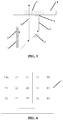
- the emitter array 1 and the receiver array 2 can be arranged in a direction perpendicular to the plane of the cover plate 4.
- an included angle a between a plane of the emitter array 1 and the receiver array 2 and the plane of the cover plate 4 is 90 degrees.
- the emitter array 1 and the receiver array 2 are arranged in a direction perpendicular to the plane of the cover plate 4, the direction of the infrared light emitted by the emitter array 1 may be parallel to the plane of the cover plate 4; and the direction of the infrared light received by the receiver array 2 may also be parallel to the plane of the cover plate, so that the display region of the mobile terminal is effectively prevented from being illuminated by the infrared light emitted by the emitter array 1 and the infrared light received by the receiver array 2.
- the two arrays may be arranged side by side, or may be arranged vertically.
- the emitter array 1 and the receiver array 2 may face the reflective mirror 3, which is not limited in the embodiment of the present disclosure.
- the orthographic projection of the emitter array 1 and the receiver array 2 on the plane of the cover plate 4 is the smallest. That is, the area occupied by the emitter array 1 and the receiver array 2 on the plane of the cover plate 4 is the smallest. In this way, it is ensured that the emitter array 1 and the receiver array 2 are closer to the edge of the cover plate 4, thereby avoiding the limitation of the emitter array 1 and the receiver array 2 on the antenna clearance region of the mobile terminal.
- the region of the infrared light emitted by the emitter array 1 may be in a tapered shape.
- a light-proof material could be arranged between said portion of the infrared light region and the display region.
- the light-proof material refers to a material which prevents infrared light from traveling through, and the light-proof material may be black paint, black rubber or the like.
- the emitter array 1 and the receiver array 2 are not perpendicular to the plane of the cover plate 4.
- the infrared light emitted by the emitter array 1 could pass through the gap 5 after being reflected by the reflective mirror 3, and the light-proof material is arranged between said portion of the infrared light region emitted by the emitter array 1 and the panel of the mobile terminal, which is not limited in the embodiment of the present disclosure.
- the included angle b between the plane of the reflective mirror 3 and the plane of the cover plate 4 is 45 degrees.
- the included angle b between the plane of the reflective mirror 3 and the plane of the cover plate 4 may be 45 degrees.
- an included angle between the plane of the reflective mirror 3 and the plane of the cover plate 4 may also be other degrees, which is not limited in the embodiment of the present disclosure. For example, referring to Fig.
- the included angle a between the plane of the reflective mirror 3 and the plane of the cover plate 4 may be 30 degrees.
- the reflective mirror 3 may be a certain distance present between the reflective mirror 3 and the gap 5.
- the infrared light emitted by the emitter array 1 is transmitted, after being reflected by the reflective mirror 3, to the gap 5, or when the infrared light reflected by the user's skin is transmitted, after passing through the gap 5, to strike the reflective mirror 3, the energy of the infrared light may be greatly attenuated due to the large distance between the reflective mirror 3 and the gap 5.
- the distance sensing assembly may further comprise a first light guide column 6 and a second light guide column 7.
- the first light guide column 6 and the second light guide column 7 are located between the reflective mirror 3 and the gap 5, and are respectively perpendicular to the plane of the cover plate 4.
- the first light guide column 6 is configured to guide the infrared light reflected by the reflective mirror 3 toward the gap 5.
- the second light guide column 7 is configured to guide the infrared light passing through the gap 5 toward the reflective mirror 3.
- the infrared light emitted by the emitter array 1 would be captured, after being reflected by the reflective mirror 3, by the first light guide column 6, and the captured infrared light would be guided toward the gap 5 to reduce the possible energy attenuation caused by the transmission of the infrared light from the reflective mirror 3 to the gap 5.
- the infrared light reflected by the user's skin is captured, after passing through the gap 5, by the second light guide column 7, and the captured infrared light is guided toward the reflective mirror 3 to reduce the possible energy attenuation caused by the transmission of the infrared light from the gap 5 to the reflective mirror 3. Therefore, it is ensured that the infrared light emitted by the emitter array 1 could be normally received, after being reflected by the user's skin, by the receiver array 2, so as to determine the distance between the panel of the mobile terminal and the user.
- first light guide column 6 and the second light guide column 7 may be a cylindrical structure or a quadrangular prismatic structure. Of course, the structure may be of other shapes, which is not limited in the embodiment of the present disclosure.
- the included angle between the first light guide column 6 or the second light guide column 7 and the plane of the cover plate 4 may not necessarily be 90 degrees. That is, the first light guide column 6 or the second light guide column 7 is not perpendicular to the plane of the cover plate 4. In this case, it merely requires that the first light guide column 6 can guide the infrared light reflected by the reflective mirror 3 toward the gap 5, and the second light guide column 7 can guide the infrared light passing through the gap 5 toward the reflective mirror 3, which is not limited in the embodiment of the present disclosure.
- the distance sensing assembly may further comprise a diffusion sheet 8 between the second light guide column 7 and the gap 5.
- the capturing angle of the second light guide column 7 can be increased to ensure that the infrared light reflected by the user's skin can be captured by the second light guide column 7 and can be guided toward the reflective mirror 3, and then the infrared light could be reflected by the reflective mirror 3 and received by the receiver array 2, so as to determine the distance between the panel of the mobile terminal and the user.
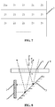
- the emitter array 1 may comprise a plurality of emitters 11.
- each of the plurality of emitters 11 is configured to emit infrared light; and the plurality of emitters 11 can emit infrared light in a direction parallel to the cover plate 4.
- the plurality of emitters 11 may emit infrared light in different directions.
- at least one emitter 11a of the plurality of emitters 11 may be a VCSEL, a light emitting diode, a laser diode, or the like.
- the emitters 11 are VCSELs
- the light emitted by the emitters 11 is laser.
- the energy of the laser is stronger, and is unlikely to diverge, so that most of the infrared light emitted by the emitter array 1 can pass through the gap 5 and be emitted out from the panel.
- the VCSEL is small in size, inexpensive, and easy to be integrated as the emitter array 1.
- the receiver array 2 may comprise a plurality of receivers 21.
- each of the plurality of receivers 21 is configured to receive infrared light; and the plurality of receivers 21 can receive infrared light in a direction parallel to the cover plate 4.
- the plurality of receivers 21 may receive the infrared light in different directions.
- At least one receiver 21a of the plurality of receivers 21 may be an SPAD, an infrared ray receiving diode, or the like.
- the receivers 21 are SPADs which can receive faint infrared light, the infrared light receiving accuracy of the receiver array 2 can be improved.
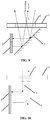
- an intersection point A of the infrared light emitted by the emitter array 1 after being reflected by the reflective mirror 3 and infrared light passing through the gap 5 to strike the reflective mirror 3 is located between the reflective mirror 3 and the gap 5.
- the emitter array 1 may comprise a plurality of emitters 11 which can emit infrared light in different directions.
- the receiver array 2 may comprise a plurality of receivers 21 which can receive infrared light in different directions.
- an intersection point A of the infrared light emitted by the emitter array 1 after being reflected by the reflective mirror 3 and the infrared light passing through the gap 5 to strike the reflective mirror 3 is located between the reflective mirror 3 and the gap 5
- an overlapping region between the region of the infrared light emitted by the emitter array 1 after being reflected by the reflective mirror 3 and the region of the infrared light passing through the gap 5 to strike the reflective mirror 3 would be larger, and in this overlapping region, infrared light emitted by the emitter array 1 can be received, after being reflected by the user's skin, by the receiver array 2. That is, when the user is in the overlapping area, the distance between the panel and the user can be accurately detected through the emitter array 1 and the receiver array 2; and the
- the intersection point A of the infrared light emitted by the emitter array 1 after being reflected by the reflective mirror 3 and the infrared light passing through the gap 5 to strike the reflective mirror 3 may be located above the gap 5, which is not limited in the embodiment of the present disclosure.
- the distance sensing assembly includes: an emitter array, a receiver array and a reflective mirror.
- the emitter array, the receiver array and the reflective mirror are located below a cover plate of the mobile terminal.
- An orthographic projection of the reflective mirror on a plane of the cover plate covers at least a portion of a gap between the cover plate and an earpiece of the mobile terminal.
- Infrared light emitted by the emitter array passes, after being reflected by the reflective mirror, through the gap; and the receiver array receives the infrared light which is reflected, after passing through the gap, by the reflective mirror.
- the mobile terminal mounted with the distance sensing assembly When using the mobile terminal mounted with the distance sensing assembly to perform distance detection, there is no need to have a specific opening located in a region other than the display region of a panel of the mobile terminal. Instead, the emitter array, the receiver array and the reflective mirror in the distance sensing assembly could be employed to detect the distance directly. As such, the panel could be prevented from being occupied by an additional hole and the area of the display region on the panel would not be limited. Thus, the screen-to-body ratio of the mobile terminal could be increased, the display performance and aesthetic effect of the mobile terminal would be improved.
- the first light guide column and the second light guide column can be arranged between the reflective mirror and the gap, to capture the infrared light.
- Fig. 10 is a schematically structural view of a distance sensing assembly according to an exemplary embodiment.
- the distance sensing assembly includes an emitter array 1, a receiver array 2, a first light guide column 6 and a second light guide column 7, and all these structures are located below the cover plate 4 of the mobile terminal.
- the first light guide column 6 is configured to guide the infrared light emitted by the emitter array 1 toward the gap 5 between the cover plate 4 and the earpiece of the mobile terminal, and the second light guide column 6 is configured to guide the infrared light passing through the gap 5 toward the receiver array 2.
- the emitter array 1, the receiver array 2, and the gap 5 can be arranged as described in the foregoing embodiments, and the details are not repeated here.
- the distance sensing assembly is configured to detect a distance between the cover plate 4 and a user.
- the infrared light emitted by the emitter array 1 is guided toward the gap 5 through the first light guide column 6, and then passes through the gap 5 to be emitted out from the cover plate 4. Outside the cover plate 4, The infrared light reflected by the use's skin passes through the gap 5 and is then guided toward the receiver array 2 through the second light guide column 7 so as to be received by the receiver array 2.
- the infrared light emitted by the emitter array 1 passes, after being guided by the first light guide column 6, through the gap 5, to be emitted out from the panel of the mobile terminal.
- the infrared light emitted from the gap 5 would be reflected after contacting the user's skin.
- the infrared light reflected by the user's skin would pass through the gap 5 and is guided toward the receiver array 2 through the second light guide column 7, so as to be received by the receiver array 2.
- the mobile terminal can determine the distance based on the infrared light emitted by the emitter array 1 and the infrared light which is received, after being reflected by the user's skin, by the receiver array 2.
- the panel Since there is no need to have a specific opening located in a region other than the display region of the panel, the panel could be prevented from being occupied by an additional hole and the area of the display region on the panel would not be limited. Thus, the screen-to-body ratio of the mobile terminal could be increased, and the display performance and the aesthetic effect of the mobile terminal would be improved.
- the distance sensing assembly is configured to form a portion of a detection circuit for a distance sensor.
- the distance sensor is configured to detect the distance between the sensor per se and the user, wherein the distance sensing assembly can determine the distance between the panel and the user based on the time when the emitter array 1 emits infrared light and the time when the receiver array 2 receives the infrared light.
- the emitter array 1 and the receiver array 2 can be arranged in a direction perpendicular to the plane of the cover plate 4.
- an included angle d between a plane of the emitter array 1 and the receiver array 2 and the plane of the cover plate 4 may be 90 degrees.
- the emitter array 1 and the receiver array 2 are arranged in a direction perpendicular to the plane of the cover plate 4, the orthographic projection of the emitter array 1 and the receiver array 2 on the plane of the cover plate 4 would be the smallest. That is, the area occupied by the emitter array 1 and the receiver array 2 on the plane of the cover plate 4 would be the smallest. In this case, it is ensured that the emitter array 1 and the receiver array 2 are closer to the edge of the panel, thereby avoiding the limitation of the emitter array 1 and the receiver array 2 on the antenna clearance region of the mobile terminal.
- the arrays may be arranged side by side, or may be arranged vertically, which is not limited in the embodiment of the present disclosure.
- a region of the infrared light emitted by the emitter array 1 may be in a tapered shape.
- a light-proof material could be arranged between the region of the uncaptured infrared light and the display region.
- the light-proof material can be as described in the above embodiments.
- the infrared light emitted by the emitter array 1 could be captured by the first light guide column 6, and the light-proof material is arranged between the region of the uncaptured infrared light and the display region, which is not limited in the embodiment of the present disclosure.
- both the first light guide column 6 and the second light guide column 7 are L-shaped light guide columns.
- the receiving end of the first light guide column 6 is perpendicular to the emitter array 1
- the guiding end of the first light guide column 6 is perpendicular to the gap 5, so that the infrared light emitted by the emitter array 1 can be captured effectively, and the captured infrared light is guided toward the gap 5.
- the receiving end of the second light guide column 7 is perpendicular to the gap 5, and the guiding end of the second light guide column 7 is perpendicular to the receiver array 2, so that the infrared light passing, after being reflected by the user's skin, through the gap 5 can be captured effectively, and the captured infrared light is guided toward the receiver array 2, thereby reducing the energy attenuation of the infrared light during transmission.
- first light guide column 6 and the second light guide column 7 may also be arc-shaped, or may be in other shapes, which is not limited in the embodiment of the present disclosure.
- the distance sensing assembly may further comprise a diffusion sheet 8 between the second light guide column 7 and the gap 5.
- the capturing angle of the second light guide column 7 can be increased to ensure that the infrared light reflected by the user's skin can be captured by the second light guide column 7 and can be guided toward the receiver array 2, so as to determine the distance between the panel of the mobile terminal and the user.
- the emitter array 1 comprises a plurality of emitters 11, and the receiver array 2 comprises a plurality of receivers 21.
- the plurality of emitters 11 in the emitter array 1 and the plurality of receivers 21 in the receiver array 2 may be arranged as described in the above embodiments, which are not repeated here.
- the distance sensing assembly includes an emitter array, a receiver array, a first light guide column and a second light guide column, and all these structures are located below the cover plate of the mobile terminal.
- the first light guide column is configured to guide the infrared light emitted by the emitter array toward the gap between the cover plate and the earpiece of the mobile terminal; and the second light guide column is configured to guide the infrared light passing through the gap toward the receiver array.
- the emitter array, the receiver array and the reflective mirror in the distance sensing assembly could be employed to detect the distance directly.
- the panel could be prevented from being occupied by an additional hole and the area of the display region on the panel would not be limited.
- the screen-to-body ratio of the mobile terminal could be increased, the display performance and aesthetic effect of the mobile terminal would be improved.
- a diffusion sheet is arranged at the receiving end of the second light guide column, namely, arranged between the second light guide column and the gap 5, so as to increase the capturing angel of the second light guide column.
- the embodiments of the present disclosure further provides mobile terminals mounted with any of the distance sensing assemblies shown in Fig. 2 to Fig. 2I or Fig. 3A to Fig. 3F .
- the mobile terminal When using the mobile terminal to perform distance detection, there is no need to have a specific opening located in a region other than the display region of a panel of the mobile terminal. As such, the panel could be prevented from being occupied by an additional hole and the area of the display region on the panel would not be limited. Thus, the screen-to-body ratio of the mobile terminal could be increased, the display performance and aesthetic effect of the mobile terminal would be improved.
- the distance sensing assembly includes: an emitter array, a receiver array and a reflective mirror.
- the emitter array, the receiver array and the reflective mirror are located below a cover plate of the mobile terminal.
- An orthographic projection of the reflective mirror on a plane of the cover plate covers at least a portion of a gap between the cover plate and an earpiece of the mobile terminal.
- Infrared light emitted by the emitter array passes, after being reflected by the reflective mirror, through the gap; and the receiver array receives the infrared light which is reflected, after passing through the gap, by the reflective mirror.
- the mobile terminal mounted with the distance sensing assembly When using the mobile terminal mounted with the distance sensing assembly to perform distance detection, there is no need to have a specific opening located in a region other than the display region of a panel of the mobile terminal. Instead, the emitter array, the receiver array and the reflective mirror in the distance sensing assembly could be employed to detect the distance directly. As such, the panel could be prevented from being occupied by an additional hole and the area of the display region on the panel would not be limited. Thus, the screen-to-body ratio of the mobile terminal could be increased, the display performance and aesthetic effect of the mobile terminal would be improved.
Landscapes
- Engineering & Computer Science (AREA)
- Physics & Mathematics (AREA)
- Computer Networks & Wireless Communication (AREA)
- General Physics & Mathematics (AREA)
- Radar, Positioning & Navigation (AREA)
- Remote Sensing (AREA)
- Electromagnetism (AREA)
- Signal Processing (AREA)
- Optical Radar Systems And Details Thereof (AREA)
- Optical Communication System (AREA)
- Telephone Set Structure (AREA)
Abstract
Description
- The present disclosure relates to the field of electronic technologies, and particularly, to a distance sensing assembly and a mobile terminal.
- With the rapid development of electronic technologies, functions of mobile terminals such as mobile phones, tablet computers and the like have become more and more powerful. In order to sense the distance between a mobile terminal and a user in real time, distance sensors represented by the infrared optical displacement sensors are widely applied to mobile terminals to realize a distance detection function.
- Currently, as shown in
Fig. 1 , usually, an opening is formed in a region other than the display region of the mobile terminal panel, and a distance sensor is arranged below the opening. The distance sensor emits and receives infrared light through the opening to perform distance detection. - The present disclosure provides a distance sensing assembly and a mobile terminal.
- According to a first aspect of the invention, a distance sensing assembly is provided, wherein the distance sensing assembly comprises: an emitter array, a receiver array and a reflective mirror, wherein the emitter array, the receiver array and the reflective mirror are located below a cover plate of a mobile terminal; an orthographic projection of the reflective mirror on a plane of the cover plate covers at least a portion of a gap between the cover plate and an earpiece of the mobile terminal; infrared light emitted by the emitter array passes, after being reflected by the reflective mirror, through the gap to be emitted; and the receiver array receives the infrared light which is reflected, after passing through the gap, by the reflective mirror.
- According to a second aspect of the invention, a distance sensing assembly is provided, wherein the distance sensing assembly comprises: an emitter array, a receiver array, a first light guide column and a second light guide column, wherein the emitter array, the receiver array, the first light guide column and the second light guide column are located below a cover plate of a mobile terminal; the first light guide column is configured to guide infrared light emitted by the emitter array toward a gap between the cover plate and an earpiece of the mobile terminal; and the second light guide column is configured to guide the infrared light passing through the gap toward the receiver array.
- According to a third aspect of the invention, a mobile terminal is provided, wherein the mobile terminal comprises the distance sensing assembly as described in the first or second aspects.
- It should be understood that both the foregoing general description and the following detailed description are only exemplary and explanatory and are not intended to limit the present disclosure.
- The accompanying drawings, which are incorporated in and constitute a part of this description, illustrate embodiments consistent with the present disclosure and, together with the description, serve to explain the principles of the present disclosure.
-
Fig. 1 is a schematically structural view of a terminal according to an exemplary embodiment; -
Fig. 2 is a schematically structural view of a first distance sensing assembly according to an exemplary embodiment; -
Fig. 3 is a schematically structural view of a second distance sensing assembly according to an exemplary embodiment; -
Fig. 4 is a schematically structural view of a third distance sensing assembly according to an exemplary embodiment; -
Fig. 5 is a schematically structural view of a fourth distance sensing assembly according to an exemplary embodiment; -
Fig. 6 is a schematically structural view of an emitter array according to an exemplary embodiment; -
Fig. 7 is a schematically structural view of a receiver array according to an exemplary embodiment; -
Fig. 8 is a schematically structural view of a fifth distance sensing assembly according to an exemplary embodiment; -
Fig. 9 is a schematically structural view of a sixth distance sensing assembly according to an exemplary embodiment; -
Fig. 10 is a schematically structural view of the first distance sensing assembly according to another exemplary embodiment; and -
Fig. 11 is a schematically structural view of the first distance sensing assembly according to yet another exemplary embodiment. - 1: emitter array; 11: emitter; 2: receiver array; 21: receiver; 3: reflective mirror; 4: cover plate; 5: gap; 6: first light guide column; 7: second light guide column; and 8: diffusion sheet.
- Hereinafter, exemplary embodiments will be described in detail. The examples thereof are shown in the drawings. In the following description when referring to the drawings, the same numerals in the different drawings denote the same or similar elements unless otherwise indicated. The examples described in the following exemplary embodiments do not represent all the examples consistent with the present disclosure. Instead, they are merely examples of devices and methods consistent with some aspects of the present disclosure as described in detail in the appended claims.
- For ease of understanding, application scenarios involved in the embodiments of the present disclosure are introduced before the detailed description of the embodiments of the present disclosure.
- With the rapid development of electronic technologies, functions of mobile terminals such as mobile phones, tablet computers and the like have become more and more powerful. In order to sense the distance between a mobile terminal and a user in real time, distance sensors represented by the infrared optical displacement sensors are widely applied to mobile terminals to realize a distance detection function. Currently, as shown in
Fig. 1 , usually, anopening 120 is formed in a region other than thedisplay region 110 of themobile terminal panel 100, and adistance sensor 130 is arranged below theopening 120. Thedistance sensor 130 emits and receives infrared light through the opening 120 to perform distance detection. As the opening 120 occupies a certain area on thepanel 100, the area occupied by thedisplay region 110 on thepanel 100 would be limited. As a result, the screen-to-body ratio of the mobile terminal is reduced, which impedes the developing trend towards full-screen mobile terminals, and adversely influences the aesthetic effect of the mobile terminal. In view of this, the embodiments of the present disclosure provide a distance sensing assembly to increase the screen-to-body ratio of the mobile terminal, improve the display performance and the aesthetic effect of the mobile terminal. - The distance sensing assembly provided by the embodiments of the present disclosure will be described in detail below with reference to the accompanying drawings.
- When the emitter array and the receiver array are arranged below the cover plate of the mobile terminal, in order to prevent the display region of the mobile terminal from being illuminated by infrared light emitted by the emitter array, the embodiments of the present disclosure adopt two manners to change the optical path, so as to effectively avoid the influence of the infrared light emitted by the emitter array on the display performance of the display region. In the first manner, the optical path is changed by arranging a reflective mirror; and in the second manner, the optical path is changed by arranging a light guide structure, such as a light guide column. The two manners will be described in detail separately through two embodiments as follows.
-
Fig. 2 is a schematically structural view of a first distance sensing assembly according to an exemplary embodiment. This embodiment of the present disclosure is configured to explain the first manner. Referring toFig. 2 , the distance sensing assembly includes anemitter array 1, areceiver array 2 and areflective mirror 3, and all these structures are located below acover plate 4 of a mobile terminal. An orthographic projection of thereflective mirror 3 on a plane of thecover plate 4 covers at least a portion of agap 5 between thecover plate 4 and an earpiece of the mobile terminal. - Referring to
Fig. 2 , the infrared light emitted by theemitter array 1 is reflected by thereflective mirror 3, then passes through thegap 5 to be emitted out. Thereceiver array 2 receives the infrared light which is reflected, after passing through thegap 5, by thereflective mirror 3. - The
emitter array 1 and thereceiver array 2 may be respectively integrated on two Integrated Circuit (IC) chips, or may be integrated on one IC chip, which is not limited in the embodiment of the present disclosure. Thegap 5 may be an optical microgap which is a tiny gap that allows infrared light to travel through but is invisible to a human eye. Moreover, a light-transparent material may be arranged in thegap 5. That is, thegap 5 may be filled with the light-transparent material, so that thegap 5 could be prevented from being blocked by other materials in the process of manufacturing the panel of the mobile terminal. The light-transparent material refers to a material which allows the infrared light to travel through, for example, the light-transparent material may be a fiber optic material or the like. - It should be noted that, the distance sensing assembly is configured to detect the distance between the
cover plate 4 and a user. The infrared light emitted by theemitter array 1 passes, after being reflected by thereflective mirror 3, through thegap 5, to be emitted out from thecover plate 4. Outside thecover plate 4, the infrared light reflected by the user's skin can pass through the gap and strike thereflective mirror 3; and then after being reflected by thereflective mirror 3, the infrared light is received by thereceiver array 2. - When the mobile terminal mounted with the distance sensing assembly performs distance detection, the infrared light emitted by the
emitter array 1 passes, after being reflected by thereflective mirror 3, through thegap 5 to be emitted out from the panel of the mobile terminal. The infrared light emitted out from thegap 5 would be reflected after contacting the user's skin. The infrared light reflected by the user's skin would pass through thegap 5 and strike thereflective mirror 3; and after being reflected by thereflective mirror 3, the infrared light is received by thereceiver array 2. In this case, the mobile terminal can determine the distance based on the infrared light emitted by theemitter array 1 and the infrared light which is received, after being reflected by the user's skin, by thereceiver array 2. Since there is no need to have a specific opening located in a region other than the display region of the panel, the panel could be prevented from being occupied by an additional hole and the area of the display region on the panel would not be limited. Thus, the screen-to-body ratio of the mobile terminal could be increased, and the display performance and the aesthetic effect of the mobile terminal would be improved. - The distance sensing assembly may be configured to form a portion of a detection circuit for a distance sensor. The distance sensor is configured to detect the distance between the sensor per se and the user, wherein the distance sensing assembly can determine the distance between the panel and the user based on the time when the
emitter array 1 emits infrared light and the time when thereceiver array 2 receives the infrared light. - When the distance sensing assembly is arranged below the cover plate, referring to
Fig. 3 , theemitter array 1 and thereceiver array 2 can be arranged in a direction perpendicular to the plane of thecover plate 4. In this case, an included angle a between a plane of theemitter array 1 and thereceiver array 2 and the plane of thecover plate 4 is 90 degrees. - It should be noted that when the
emitter array 1 and thereceiver array 2 are arranged in a direction perpendicular to the plane of thecover plate 4, the direction of the infrared light emitted by theemitter array 1 may be parallel to the plane of thecover plate 4; and the direction of the infrared light received by thereceiver array 2 may also be parallel to the plane of the cover plate, so that the display region of the mobile terminal is effectively prevented from being illuminated by the infrared light emitted by theemitter array 1 and the infrared light received by thereceiver array 2. When arranging theemitter array 1 and thereceiver array 2, the two arrays may be arranged side by side, or may be arranged vertically. Moreover, theemitter array 1 and thereceiver array 2 may face thereflective mirror 3, which is not limited in the embodiment of the present disclosure. - In addition, when the
emitter array 1 and thereceiver array 2 are arranged in a direction perpendicular to the plane of thecover plate 4, the orthographic projection of theemitter array 1 and thereceiver array 2 on the plane of thecover plate 4 is the smallest. That is, the area occupied by theemitter array 1 and thereceiver array 2 on the plane of thecover plate 4 is the smallest. In this way, it is ensured that theemitter array 1 and thereceiver array 2 are closer to the edge of thecover plate 4, thereby avoiding the limitation of theemitter array 1 and thereceiver array 2 on the antenna clearance region of the mobile terminal. - In a practical application, when the
emitter array 1 is perpendicular to the plane of thecover plate 4, the region of the infrared light emitted by theemitter array 1 may be in a tapered shape. In this case, in order to prevent the display region of the mobile terminal from being illuminated by a portion of infrared light which is not parallel to the plane of thecover plate 4, a light-proof material could be arranged between said portion of the infrared light region and the display region. The light-proof material refers to a material which prevents infrared light from traveling through, and the light-proof material may be black paint, black rubber or the like. Of course, when arranging theemitter array 1 and thereceiver array 2 below thecover plate 4, it would be feasible that theemitter array 1 and thereceiver array 2 are not perpendicular to the plane of thecover plate 4. In this case, it merely requires that the infrared light emitted by theemitter array 1 could pass through thegap 5 after being reflected by thereflective mirror 3, and the light-proof material is arranged between said portion of the infrared light region emitted by theemitter array 1 and the panel of the mobile terminal, which is not limited in the embodiment of the present disclosure. - Referring to
Fig. 3 , the included angle b between the plane of thereflective mirror 3 and the plane of thecover plate 4 is 45 degrees. - It should be noted that when each of the
emitter array 1 and thereceiver array 2 is perpendicular to the plane of thecover plate 4, the infrared light emitted by theemitter array 1 is parallel to the plane of thecover plate 4. In order to ensure that the emitted infrared light is perpendicular, after being reflected by thereflective mirror 3, to the plane of thecover plate 4, and the infrared light received by thereceiver array 2 is parallel to the plane of thecover plate 4, the included angle b between the plane of thereflective mirror 3 and the plane of thecover plate 4 may be 45 degrees. - Of course, for the portion of the infrared light emitted by the
emitter array 1 which is not parallel to the plane of thecover plate 4, in order to ensure that the infrared light is perpendicular, after being reflected by thereflective mirror 3, to the plane of thecover plate 4, an included angle between the plane of thereflective mirror 3 and the plane of thecover plate 4 may also be other degrees, which is not limited in the embodiment of the present disclosure. For example, referring toFig. 4 , when an included angle c between the infrared light emitted by theemitter array 1 and the plane of thecover plate 4 is 30 degrees, in order to ensure that the infrared light after being reflected by thereflective mirror 3 is perpendicular to the plane of thecover plate 4, the included angle a between the plane of thereflective mirror 3 and the plane of thecover plate 4 may be 30 degrees. - In addition, due to the limitation of the earpiece, there may be a certain distance present between the
reflective mirror 3 and thegap 5. As such, when the infrared light emitted by theemitter array 1 is transmitted, after being reflected by thereflective mirror 3, to thegap 5, or when the infrared light reflected by the user's skin is transmitted, after passing through thegap 5, to strike thereflective mirror 3, the energy of the infrared light may be greatly attenuated due to the large distance between thereflective mirror 3 and thegap 5. As a result, it is likely that the infrared light which is emitted out, after passing through thegap 5, from thecover plate 4 cannot reach the user's skin, or the infrared light reflected by the user's skin cannot be received, after being reflected by thereflective mirror 3, by thereceiver array 2, so that the distance between the panel of the mobile terminal and the user cannot be accurately detected. - Therefore, referring to
Fig. 5 , the distance sensing assembly may further comprise a firstlight guide column 6 and a secondlight guide column 7. The firstlight guide column 6 and the secondlight guide column 7 are located between thereflective mirror 3 and thegap 5, and are respectively perpendicular to the plane of thecover plate 4. The firstlight guide column 6 is configured to guide the infrared light reflected by thereflective mirror 3 toward thegap 5. The secondlight guide column 7 is configured to guide the infrared light passing through thegap 5 toward thereflective mirror 3. As such the infrared light emitted by theemitter array 1 would be captured, after being reflected by thereflective mirror 3, by the firstlight guide column 6, and the captured infrared light would be guided toward thegap 5 to reduce the possible energy attenuation caused by the transmission of the infrared light from thereflective mirror 3 to thegap 5. Or, the infrared light reflected by the user's skin is captured, after passing through thegap 5, by the secondlight guide column 7, and the captured infrared light is guided toward thereflective mirror 3 to reduce the possible energy attenuation caused by the transmission of the infrared light from thegap 5 to thereflective mirror 3. Therefore, it is ensured that the infrared light emitted by theemitter array 1 could be normally received, after being reflected by the user's skin, by thereceiver array 2, so as to determine the distance between the panel of the mobile terminal and the user. - It should be noted that, the first
light guide column 6 and the secondlight guide column 7 may be a cylindrical structure or a quadrangular prismatic structure. Of course, the structure may be of other shapes, which is not limited in the embodiment of the present disclosure. The included angle between the firstlight guide column 6 or the secondlight guide column 7 and the plane of thecover plate 4 may not necessarily be 90 degrees. That is, the firstlight guide column 6 or the secondlight guide column 7 is not perpendicular to the plane of thecover plate 4. In this case, it merely requires that the firstlight guide column 6 can guide the infrared light reflected by thereflective mirror 3 toward thegap 5, and the secondlight guide column 7 can guide the infrared light passing through thegap 5 toward thereflective mirror 3, which is not limited in the embodiment of the present disclosure. - In addition, due to the limitation of the earpiece of the mobile terminal, there may be a large distance present between the upper end of the second
light guide column 7 and thegap 5, so that the capturing angle of the secondlight guide column 7 upon capturing of the infrared light would be small. In this case, if the secondlight guide column 7 cannot capture any infrared light due to the small capturing angle, thereceiver array 2 could not receive the infrared light reflected by the user's skin, so that the distance between the panel of the mobile terminal and the user could not be determined. Therefore, referring toFig. 5 , the distance sensing assembly may further comprise adiffusion sheet 8 between the secondlight guide column 7 and thegap 5. Through thediffusion sheet 8, the capturing angle of the secondlight guide column 7 can be increased to ensure that the infrared light reflected by the user's skin can be captured by the secondlight guide column 7 and can be guided toward thereflective mirror 3, and then the infrared light could be reflected by thereflective mirror 3 and received by thereceiver array 2, so as to determine the distance between the panel of the mobile terminal and the user. - Referring to
Fig. 6 , theemitter array 1 may comprise a plurality ofemitters 11. - It should be noted that, each of the plurality of
emitters 11 is configured to emit infrared light; and the plurality ofemitters 11 can emit infrared light in a direction parallel to thecover plate 4. Of course, the plurality ofemitters 11 may emit infrared light in different directions. For example, at least oneemitter 11a of the plurality ofemitters 11 may be a VCSEL, a light emitting diode, a laser diode, or the like. - In addition, when the
emitters 11 are VCSELs, the light emitted by theemitters 11 is laser. The energy of the laser is stronger, and is unlikely to diverge, so that most of the infrared light emitted by theemitter array 1 can pass through thegap 5 and be emitted out from the panel. Moreover, the VCSEL is small in size, inexpensive, and easy to be integrated as theemitter array 1. - Referring to
Fig. 7 , thereceiver array 2 may comprise a plurality ofreceivers 21. - It should be noted that, each of the plurality of
receivers 21 is configured to receive infrared light; and the plurality ofreceivers 21 can receive infrared light in a direction parallel to thecover plate 4. Of course, the plurality ofreceivers 21 may receive the infrared light in different directions. At least onereceiver 21a of the plurality ofreceivers 21 may be an SPAD, an infrared ray receiving diode, or the like. - In addition, when the
receivers 21 are SPADs which can receive faint infrared light, the infrared light receiving accuracy of thereceiver array 2 can be improved. - Referring to
Fig. 8 , an intersection point A of the infrared light emitted by theemitter array 1 after being reflected by thereflective mirror 3 and infrared light passing through thegap 5 to strike thereflective mirror 3 is located between thereflective mirror 3 and thegap 5. - It should be noted that, the
emitter array 1 may comprise a plurality ofemitters 11 which can emit infrared light in different directions. Thereceiver array 2 may comprise a plurality ofreceivers 21 which can receive infrared light in different directions. When an intersection point A of the infrared light emitted by theemitter array 1 after being reflected by thereflective mirror 3 and the infrared light passing through thegap 5 to strike thereflective mirror 3 is located between thereflective mirror 3 and thegap 5, an overlapping region between the region of the infrared light emitted by theemitter array 1 after being reflected by thereflective mirror 3 and the region of the infrared light passing through thegap 5 to strike thereflective mirror 3 would be larger, and in this overlapping region, infrared light emitted by theemitter array 1 can be received, after being reflected by the user's skin, by thereceiver array 2. That is, when the user is in the overlapping area, the distance between the panel and the user can be accurately detected through theemitter array 1 and thereceiver array 2; and the detection range is wider. - Of course, in a practical application, as shown in
Fig. 9 , the intersection point A of the infrared light emitted by theemitter array 1 after being reflected by thereflective mirror 3 and the infrared light passing through thegap 5 to strike thereflective mirror 3 may be located above thegap 5, which is not limited in the embodiment of the present disclosure. - In the embodiments of the present disclosure, the distance sensing assembly includes: an emitter array, a receiver array and a reflective mirror. The emitter array, the receiver array and the reflective mirror are located below a cover plate of the mobile terminal. An orthographic projection of the reflective mirror on a plane of the cover plate covers at least a portion of a gap between the cover plate and an earpiece of the mobile terminal. Infrared light emitted by the emitter array passes, after being reflected by the reflective mirror, through the gap; and the receiver array receives the infrared light which is reflected, after passing through the gap, by the reflective mirror. When using the mobile terminal mounted with the distance sensing assembly to perform distance detection, there is no need to have a specific opening located in a region other than the display region of a panel of the mobile terminal. Instead, the emitter array, the receiver array and the reflective mirror in the distance sensing assembly could be employed to detect the distance directly. As such, the panel could be prevented from being occupied by an additional hole and the area of the display region on the panel would not be limited. Thus, the screen-to-body ratio of the mobile terminal could be increased, the display performance and aesthetic effect of the mobile terminal would be improved. In addition, for the purpose of avoiding the condition that due to energy attenuation in the transmission process of infrared light, the infrared light passing through the gap could not be reflected by the user's skin, or the infrared light passing through the gap and then striking the reflective mirror could not be received by the receiver array after being reflected by the reflective mirror, the first light guide column and the second light guide column can be arranged between the reflective mirror and the gap, to capture the infrared light. As such, the energy attenuation could be avoided and the accuracy of the detection of the distance between the panel and the user could be ensured.
-
Fig. 10 is a schematically structural view of a distance sensing assembly according to an exemplary embodiment. The embodiments of the present disclosure demonstrates the above second manner. Referring toFig. 10 , the distance sensing assembly includes anemitter array 1, areceiver array 2, a firstlight guide column 6 and a secondlight guide column 7, and all these structures are located below thecover plate 4 of the mobile terminal. - Referring to
Fig. 10 , the firstlight guide column 6 is configured to guide the infrared light emitted by theemitter array 1 toward thegap 5 between thecover plate 4 and the earpiece of the mobile terminal, and the secondlight guide column 6 is configured to guide the infrared light passing through thegap 5 toward thereceiver array 2. - The
emitter array 1, thereceiver array 2, and thegap 5 can be arranged as described in the foregoing embodiments, and the details are not repeated here. - It should be noted that the distance sensing assembly is configured to detect a distance between the
cover plate 4 and a user. The infrared light emitted by theemitter array 1 is guided toward thegap 5 through the firstlight guide column 6, and then passes through thegap 5 to be emitted out from thecover plate 4. Outside thecover plate 4, The infrared light reflected by the use's skin passes through thegap 5 and is then guided toward thereceiver array 2 through the secondlight guide column 7 so as to be received by thereceiver array 2. - When the mobile terminal mounted with the distance sensing assembly performs distance detection, the infrared light emitted by the
emitter array 1 passes, after being guided by the firstlight guide column 6, through thegap 5, to be emitted out from the panel of the mobile terminal. The infrared light emitted from thegap 5 would be reflected after contacting the user's skin. The infrared light reflected by the user's skin would pass through thegap 5 and is guided toward thereceiver array 2 through the secondlight guide column 7, so as to be received by thereceiver array 2. At this time, the mobile terminal can determine the distance based on the infrared light emitted by theemitter array 1 and the infrared light which is received, after being reflected by the user's skin, by thereceiver array 2. Since there is no need to have a specific opening located in a region other than the display region of the panel, the panel could be prevented from being occupied by an additional hole and the area of the display region on the panel would not be limited. Thus, the screen-to-body ratio of the mobile terminal could be increased, and the display performance and the aesthetic effect of the mobile terminal would be improved. - The distance sensing assembly is configured to form a portion of a detection circuit for a distance sensor. The distance sensor is configured to detect the distance between the sensor per se and the user, wherein the distance sensing assembly can determine the distance between the panel and the user based on the time when the
emitter array 1 emits infrared light and the time when thereceiver array 2 receives the infrared light. - When arranging the distance sensing assembly below the
cover plate 4, referring toFig. 11 , theemitter array 1 and thereceiver array 2 can be arranged in a direction perpendicular to the plane of thecover plate 4. In this case, an included angle d between a plane of theemitter array 1 and thereceiver array 2 and the plane of thecover plate 4 may be 90 degrees. - It should be noted that, when the
emitter array 1 and thereceiver array 2 are arranged in a direction perpendicular to the plane of thecover plate 4, the orthographic projection of theemitter array 1 and thereceiver array 2 on the plane of thecover plate 4 would be the smallest. That is, the area occupied by theemitter array 1 and thereceiver array 2 on the plane of thecover plate 4 would be the smallest. In this case, it is ensured that theemitter array 1 and thereceiver array 2 are closer to the edge of the panel, thereby avoiding the limitation of theemitter array 1 and thereceiver array 2 on the antenna clearance region of the mobile terminal. When arranging theemitter array 1 and thereceiver array 2, the arrays may be arranged side by side, or may be arranged vertically, which is not limited in the embodiment of the present disclosure. - In a practical application, when the
emitter array 1 is perpendicular to the plane of the cover plate, a region of the infrared light emitted by theemitter array 1 may be in a tapered shape. In this case, in order to prevent the display region of the mobile terminal from being illuminated by infrared light which is not captured by the firstlight guide column 6, a light-proof material could be arranged between the region of the uncaptured infrared light and the display region. The light-proof material can be as described in the above embodiments. Of course, when arranging theemitter array 1 and thereceiver array 2 below the cover plate, it would be feasible that theemitter array 1 and thereceiver array 2 are not perpendicular to the plane of thecover plate 4. In this case, it merely requires that the infrared light emitted by theemitter array 1 could be captured by the firstlight guide column 6, and the light-proof material is arranged between the region of the uncaptured infrared light and the display region, which is not limited in the embodiment of the present disclosure. - Referring to
Fig. 10 or11 , both the firstlight guide column 6 and the secondlight guide column 7 are L-shaped light guide columns. In this case, the receiving end of the firstlight guide column 6 is perpendicular to theemitter array 1, and the guiding end of the firstlight guide column 6 is perpendicular to thegap 5, so that the infrared light emitted by theemitter array 1 can be captured effectively, and the captured infrared light is guided toward thegap 5. The receiving end of the secondlight guide column 7 is perpendicular to thegap 5, and the guiding end of the secondlight guide column 7 is perpendicular to thereceiver array 2, so that the infrared light passing, after being reflected by the user's skin, through thegap 5 can be captured effectively, and the captured infrared light is guided toward thereceiver array 2, thereby reducing the energy attenuation of the infrared light during transmission. - Of course, the first
light guide column 6 and the secondlight guide column 7 may also be arc-shaped, or may be in other shapes, which is not limited in the embodiment of the present disclosure. - In addition, due to the limitation of the earpiece of the mobile terminal, there may be a large distance present between the upper end of the second
light guide column 7 and thegap 5, so that the capturing angle of the secondlight guide column 7 upon capturing of the infrared light would be small. In this case, if the secondlight guide column 7 cannot capture the infrared light due to the small capturing angle, thereceiver array 2 could not receive the infrared light reflected by the user's skin, so that the distance between the panel of the mobile terminal and the user could not be determined. Therefore, referring toFig. 11 , the distance sensing assembly may further comprise adiffusion sheet 8 between the secondlight guide column 7 and thegap 5. Through thediffusion sheet 8, the capturing angle of the secondlight guide column 7 can be increased to ensure that the infrared light reflected by the user's skin can be captured by the secondlight guide column 7 and can be guided toward thereceiver array 2, so as to determine the distance between the panel of the mobile terminal and the user. - The
emitter array 1 comprises a plurality ofemitters 11, and thereceiver array 2 comprises a plurality ofreceivers 21. The plurality ofemitters 11 in theemitter array 1 and the plurality ofreceivers 21 in thereceiver array 2 may be arranged as described in the above embodiments, which are not repeated here. - In the embodiments of the present disclosure, the distance sensing assembly includes an emitter array, a receiver array, a first light guide column and a second light guide column, and all these structures are located below the cover plate of the mobile terminal. The first light guide column is configured to guide the infrared light emitted by the emitter array toward the gap between the cover plate and the earpiece of the mobile terminal; and the second light guide column is configured to guide the infrared light passing through the gap toward the receiver array. When using the mobile terminal mounted with the distance sensing assembly to perform distance detection, there is no need to have a specific opening located in a region other than the display region of a panel of the mobile terminal. Instead, the emitter array, the receiver array and the reflective mirror in the distance sensing assembly could be employed to detect the distance directly. As such, the panel could be prevented from being occupied by an additional hole and the area of the display region on the panel would not be limited. Thus, the screen-to-body ratio of the mobile terminal could be increased, the display performance and aesthetic effect of the mobile terminal would be improved. In addition, for the purpose of avoiding the condition that the second light guide column cannot capture the infrared light reflected by the user's skin, a diffusion sheet is arranged at the receiving end of the second light guide column, namely, arranged between the second light guide column and the
gap 5, so as to increase the capturing angel of the second light guide column. Thus, it is ensured that the second light guide column can capture the infrared light reflected by the user's skin and can guide it to the receiver array, thereby guaranteeing the accuracy of the detection of the distance between the panel and the user. - The embodiments of the present disclosure further provides mobile terminals mounted with any of the distance sensing assemblies shown in
Fig. 2 to Fig. 2I orFig. 3A to Fig. 3F . When using the mobile terminal to perform distance detection, there is no need to have a specific opening located in a region other than the display region of a panel of the mobile terminal. As such, the panel could be prevented from being occupied by an additional hole and the area of the display region on the panel would not be limited. Thus, the screen-to-body ratio of the mobile terminal could be increased, the display performance and aesthetic effect of the mobile terminal would be improved. - The above aspects of the present disclosure may have the following advantages. In the aspects of the present disclosure, the distance sensing assembly includes: an emitter array, a receiver array and a reflective mirror. The emitter array, the receiver array and the reflective mirror are located below a cover plate of the mobile terminal. An orthographic projection of the reflective mirror on a plane of the cover plate covers at least a portion of a gap between the cover plate and an earpiece of the mobile terminal. Infrared light emitted by the emitter array passes, after being reflected by the reflective mirror, through the gap; and the receiver array receives the infrared light which is reflected, after passing through the gap, by the reflective mirror. When using the mobile terminal mounted with the distance sensing assembly to perform distance detection, there is no need to have a specific opening located in a region other than the display region of a panel of the mobile terminal. Instead, the emitter array, the receiver array and the reflective mirror in the distance sensing assembly could be employed to detect the distance directly. As such, the panel could be prevented from being occupied by an additional hole and the area of the display region on the panel would not be limited. Thus, the screen-to-body ratio of the mobile terminal could be increased, the display performance and aesthetic effect of the mobile terminal would be improved.
- Other embodiments of the present disclosure will be apparent to those skilled in the art from the consideration of the specification after implementing the invention disclosed herein. This application is intended to cover any variations, uses, or adaptations of the present disclosure following the general principles thereof and including common knowledge or conventional technical measures which are not disclosed herein. The specification and embodiments are to be considered as exemplary only, with a true scope of the present disclosure indicated by the following claims.
- It shall be appreciated that, the present disclosure is not limited to the exact construction which has been described above and illustrated in the accompanying drawings, while various modifications and changes can be made without departing from the scope thereof. It is intended that the scope of the present disclosure shall only be limited by the appended claims.
Claims (15)
- A distance sensing assembly, comprising: an emitter array (1), a receiver array (2) and a reflective mirror (3), wherein
the emitter array (1), the receiver array (2) and the reflective mirror (3) are located below a cover plate (4) of a mobile terminal; an orthographic projection of the reflective mirror (3) on a plane of the cover plate (4) covers at least a portion of a gap (5) between the cover plate (4) and an earpiece of the mobile terminal;
infrared light emitted by the emitter array (1) passes, after being reflected by the reflective mirror (3), through the gap (5) to be emitted out; and the receiver array (2) receives the infrared light which is reflected, after passing through the gap (5), by the reflective mirror (3). - The distance sensing assembly of claim 1, further comprising a first light guide column (6) and a second light guide column (7), wherein
the first light guide column (6) and the second light guide column (7) are located between the reflective mirror (3) and the gap (5), and are respectively perpendicular to the plane of the cover plate (4);
the first light guide column (6) is configured to guide the infrared light reflected by the reflective mirror (3) toward the gap (5); and the second light guide column (7) is configured to guide the infrared light passing through the gap (5) toward the reflective mirror (3). - The distance sensing assembly of claim 2, further comprising a diffusion sheet (8) located between the second light guide column (7) and the gap (5).
- The distance sensing assembly of claim 1, wherein the emitter array (1) and the receiver array (2) are arranged in a direction perpendicular to the plane of the cover plate (4).
- The distance sensing assembly of claim 4, wherein an included angle between a plane of the reflective mirror (3) and the plane of the cover plate (4) is 45 degrees.
- The distance sensing assembly of claim 1, wherein an intersection point of the infrared light emitted by the emitter array (1) after being reflected by the reflective mirror (3) and the infrared light passing through the gap (5) to strike the reflective mirror (3) is located between the reflective mirror (3) and the gap (5).
- The distance sensing assembly of claim 1, wherein the emitter array (1) comprises a plurality of emitters; and at least one of the plurality of the emitters is a vertical-cavity surface-emitting laser (VCSEL), or
the receiver array (2) comprises a plurality of receivers; and at least one of the plurality of the receivers is a single-photon avalanche diode (SPAD). - The distance sensing assembly of claim 1, wherein the distance sensing assembly is configured to form a portion of a detection circuit for a distance sensor.
- A distance sensing assembly, comprising: an emitter array (1), a receiver array (2), a first light guide column (6) and a second light guide column (7), wherein
the emitter array (1), the receiver array (2), the first light guide column (6) and the second light guide column (7) are located below a cover plate (4) of a mobile terminal; the first light guide column (6) is configured to guide infrared light emitted by the emitter array (1) toward a gap (5) between the cover plate (4) and an earpiece of the mobile terminal; and the second light guide column (7) is configured to guide the infrared light passing through the gap (5) toward the receiver array (2). - The distance sensing assembly of claim 9, further comprising a diffusion sheet (8) located between the second light guide column (7) and the gap (5).
- The distance sensing assembly of claim 9 or 10, wherein the emitter array (1) and the receiver array (2) are arranged in a direction perpendicular to a plane of the cover plate (4).
- The distance sensing assembly of claim 11, wherein both the first light guide column (6) and the second light guide column (7) are L-shaped light guide columns.
- The distance sensing assembly of claim 9, wherein the emitter array (1) comprises a plurality of emitters; and at least one of the plurality of the emitters is a vertical-cavity surface-emitting laser (VCSEL), or
the receiver array (2) comprises a plurality of receivers; and at least one of the plurality of the receivers is a single-photon avalanche diode (SPAD). - The distance sensing assembly of claim 9, wherein the distance sensing assembly is configured to form a portion of a detection circuit for a distance sensor.
- A mobile terminal, comprising the distance sensing assembly of any of claims 1-14.
Applications Claiming Priority (1)
| Application Number | Priority Date | Filing Date | Title |
|---|---|---|---|
| CN201810367784.XA CN108828612B (en) | 2018-04-23 | 2018-04-23 | Distance sensing components and mobile terminals |
Publications (2)
| Publication Number | Publication Date |
|---|---|
| EP3564700A1 true EP3564700A1 (en) | 2019-11-06 |
| EP3564700B1 EP3564700B1 (en) | 2025-10-01 |
Family
ID=64154664
Family Applications (1)
| Application Number | Title | Priority Date | Filing Date |
|---|---|---|---|
| EP19169391.0A Active EP3564700B1 (en) | 2018-04-23 | 2019-04-16 | Distance sensing assembly and mobile terminal |
Country Status (3)
| Country | Link |
|---|---|
| US (1) | US10983211B2 (en) |
| EP (1) | EP3564700B1 (en) |
| CN (1) | CN108828612B (en) |
Families Citing this family (9)
| Publication number | Priority date | Publication date | Assignee | Title |
|---|---|---|---|---|
| CN109309738B (en) * | 2018-08-01 | 2021-08-17 | 荣耀终端有限公司 | Proximity Light Sensor Components and Electronics |
| CN111244192B (en) * | 2018-11-29 | 2022-02-15 | 北京小米移动软件有限公司 | SPAD's control circuit, distance inductor module and mobile terminal |
| CN111243553B (en) * | 2018-11-29 | 2021-06-08 | 北京小米移动软件有限公司 | Terminal screen control method, device and storage medium |
| CN111381238A (en) * | 2018-12-28 | 2020-07-07 | 北京小米移动软件有限公司 | Distance sensor, mobile terminal, method and device for detecting distance |
| CN110333515B (en) * | 2019-04-24 | 2022-03-29 | 维沃移动通信有限公司 | Terminal |
| CN110779557B (en) * | 2019-10-23 | 2022-05-20 | 上海龙旗科技股份有限公司 | Sensor and equipment |
| CN110958335A (en) * | 2019-11-01 | 2020-04-03 | 华为技术有限公司 | Terminal Equipment |
| US12177602B2 (en) | 2021-02-23 | 2024-12-24 | Apple Inc. | Light-folded projector |
| CN215986475U (en) * | 2021-07-02 | 2022-03-08 | 美智纵横科技有限责任公司 | Distance measuring device and sweeping robot |
Citations (3)
| Publication number | Priority date | Publication date | Assignee | Title |
|---|---|---|---|---|
| US20170003379A1 (en) * | 2015-07-01 | 2017-01-05 | Stmicroelectronics (Research & Development) Limited | Photonics device |
| US20170126868A1 (en) * | 2015-10-30 | 2017-05-04 | Essential Products, Inc. | System and method for reducing the number of ports associated with a mobile device |
| US20180031728A1 (en) * | 2015-02-24 | 2018-02-01 | Lg Innotek Co., Ltd. | Proximity Sensor, Camera Module Comprising Same, and Mobile Terminal Comprising Same |
Family Cites Families (14)
| Publication number | Priority date | Publication date | Assignee | Title |
|---|---|---|---|---|
| US5317140A (en) * | 1992-11-24 | 1994-05-31 | Dunthorn David I | Diffusion-assisted position location particularly for visual pen detection |
| JP5473044B2 (en) * | 2009-01-31 | 2014-04-16 | 株式会社キーエンス | Safety photoelectric switch |
| KR20110056892A (en) * | 2009-11-23 | 2011-05-31 | 삼성전자주식회사 | Multi-touch sensing device of LCD display device and multi-touch sensing method using same |
| CN102843473A (en) * | 2012-08-31 | 2012-12-26 | 惠州Tcl移动通信有限公司 | Mobile phone and distance sensing device thereof |
| US9279726B2 (en) * | 2013-08-06 | 2016-03-08 | Avago Technologies General Ip (Singapore) Pte. Ltd. | Optical device with reduced crosstalk |
| CN204119279U (en) * | 2014-06-18 | 2015-01-21 | 锤子科技(北京)有限公司 | A kind of mobile terminal |
| KR102383790B1 (en) * | 2015-05-22 | 2022-04-08 | 삼성전자주식회사 | Environment recognition method and electronic device thereof |
| DE102015015651B3 (en) * | 2015-12-02 | 2017-04-13 | Lessmüller Lasertechnik GmbH | Monitoring device, processing system and method for work space monitoring for laser material processing |
| CN205545451U (en) * | 2016-01-20 | 2016-08-31 | 上海华掌通信技术有限公司 | Trinity mobile handset structure |
| CN205610701U (en) * | 2016-04-07 | 2016-09-28 | 广东欧珀移动通信有限公司 | mobile terminal |
| CN106506746B (en) * | 2016-12-06 | 2023-08-25 | Oppo广东移动通信有限公司 | Panel, sensor assembly and mobile terminal |
| CN106453725B (en) * | 2016-12-06 | 2023-04-07 | Oppo广东移动通信有限公司 | Terminal device |
| CN107071099B (en) * | 2017-03-07 | 2021-01-15 | Oppo广东移动通信有限公司 | Terminal |
| CN107888726A (en) * | 2017-11-22 | 2018-04-06 | 广东欧珀移动通信有限公司 | Display screen component and electronic equipment |
-
2018
- 2018-04-23 CN CN201810367784.XA patent/CN108828612B/en not_active Expired - Fee Related
-
2019
- 2019-04-16 EP EP19169391.0A patent/EP3564700B1/en active Active
- 2019-04-19 US US16/389,464 patent/US10983211B2/en not_active Expired - Fee Related
Patent Citations (3)
| Publication number | Priority date | Publication date | Assignee | Title |
|---|---|---|---|---|
| US20180031728A1 (en) * | 2015-02-24 | 2018-02-01 | Lg Innotek Co., Ltd. | Proximity Sensor, Camera Module Comprising Same, and Mobile Terminal Comprising Same |
| US20170003379A1 (en) * | 2015-07-01 | 2017-01-05 | Stmicroelectronics (Research & Development) Limited | Photonics device |
| US20170126868A1 (en) * | 2015-10-30 | 2017-05-04 | Essential Products, Inc. | System and method for reducing the number of ports associated with a mobile device |
Also Published As
| Publication number | Publication date |
|---|---|
| US20190324142A1 (en) | 2019-10-24 |
| EP3564700B1 (en) | 2025-10-01 |
| CN108828612A (en) | 2018-11-16 |
| US10983211B2 (en) | 2021-04-20 |
| CN108828612B (en) | 2021-03-09 |
Similar Documents
| Publication | Publication Date | Title |
|---|---|---|
| US10983211B2 (en) | Distance sensing assembly and mobile terminal including the same | |
| US11347277B2 (en) | Display assembly and electronic device using signal reflection for user | |
| CN101971056B (en) | Light barrier and method for detecting objects | |
| JP6175835B2 (en) | Laser radar equipment | |
| US9588224B2 (en) | Proximity-sensing device | |
| US10559708B2 (en) | Proximity sensing module with dual transmitters | |
| US9927553B2 (en) | Miniaturized optical proximity sensor | |
| US20220171028A1 (en) | Flash lidar | |
| US10473764B2 (en) | Proximity sensor package having one or more grooves in a module cap | |
| US20200081122A1 (en) | Proximity sensor | |
| JP2019138675A (en) | Object detecting device | |
| US20230154359A1 (en) | Display assembly and display device | |
| US20230152426A1 (en) | Display Assembly and Display Device | |
| JP6537948B2 (en) | Proximity sensor and electronic device | |
| US20220244380A1 (en) | Optical isolation apparatus | |
| CN111131552A (en) | Electronic equipment | |
| JP6444644B2 (en) | Optical path changing member, casing and portable terminal | |
| US11061248B2 (en) | Noncontact operation detecting device | |
| US20200096635A1 (en) | Object detection device and method for monitoring a light projection surface for a penetration by an object | |
| US20190204078A1 (en) | Vision Laser Receiver | |
| EP3748411B1 (en) | Electronic device | |
| WO2025016449A1 (en) | LIGHT DETECTOR CHIP, LIGHT EMITTER CHIP, AND LiDAR | |
| KR102507926B1 (en) | Micro-optics system | |
| JP2018181762A (en) | Proximity sensor and electronic equipment | |
| US11719789B2 (en) | Optical proximity sensor and portable terminal apparatus for adjusting degree of freedom in arrangement position |
Legal Events
| Date | Code | Title | Description |
|---|---|---|---|
| PUAI | Public reference made under article 153(3) epc to a published international application that has entered the european phase |
Free format text: ORIGINAL CODE: 0009012 |
|
| STAA | Information on the status of an ep patent application or granted ep patent |
Free format text: STATUS: THE APPLICATION HAS BEEN PUBLISHED |
|
| AK | Designated contracting states |
Kind code of ref document: A1 Designated state(s): AL AT BE BG CH CY CZ DE DK EE ES FI FR GB GR HR HU IE IS IT LI LT LU LV MC MK MT NL NO PL PT RO RS SE SI SK SM TR |
|
| AX | Request for extension of the european patent |
Extension state: BA ME |
|
| STAA | Information on the status of an ep patent application or granted ep patent |
Free format text: STATUS: REQUEST FOR EXAMINATION WAS MADE |
|
| 17P | Request for examination filed |
Effective date: 20200504 |
|
| RBV | Designated contracting states (corrected) |
Designated state(s): AL AT BE BG CH CY CZ DE DK EE ES FI FR GB GR HR HU IE IS IT LI LT LU LV MC MK MT NL NO PL PT RO RS SE SI SK SM TR |
|
| STAA | Information on the status of an ep patent application or granted ep patent |
Free format text: STATUS: EXAMINATION IS IN PROGRESS |
|
| 17Q | First examination report despatched |
Effective date: 20211215 |
|
| GRAP | Despatch of communication of intention to grant a patent |
Free format text: ORIGINAL CODE: EPIDOSNIGR1 |
|
| STAA | Information on the status of an ep patent application or granted ep patent |
Free format text: STATUS: GRANT OF PATENT IS INTENDED |
|
| INTG | Intention to grant announced |
Effective date: 20250423 |
|
| GRAS | Grant fee paid |
Free format text: ORIGINAL CODE: EPIDOSNIGR3 |
|
| GRAA | (expected) grant |
Free format text: ORIGINAL CODE: 0009210 |
|
| STAA | Information on the status of an ep patent application or granted ep patent |
Free format text: STATUS: THE PATENT HAS BEEN GRANTED |
|
| AK | Designated contracting states |
Kind code of ref document: B1 Designated state(s): AL AT BE BG CH CY CZ DE DK EE ES FI FR GB GR HR HU IE IS IT LI LT LU LV MC MK MT NL NO PL PT RO RS SE SI SK SM TR |
|
| REG | Reference to a national code |
Ref country code: GB Ref legal event code: FG4D Ref country code: CH Ref legal event code: F10 Free format text: ST27 STATUS EVENT CODE: U-0-0-F10-F00 (AS PROVIDED BY THE NATIONAL OFFICE) Effective date: 20251001 |
|
| REG | Reference to a national code |
Ref country code: DE Ref legal event code: R096 Ref document number: 602019076288 Country of ref document: DE |
|
| REG | Reference to a national code |
Ref country code: IE Ref legal event code: FG4D |
|
| REG | Reference to a national code |
Ref country code: NL Ref legal event code: MP Effective date: 20251001 |
|
| REG | Reference to a national code |
Ref country code: AT Ref legal event code: MK05 Ref document number: 1842996 Country of ref document: AT Kind code of ref document: T Effective date: 20251001 |
|
| PG25 | Lapsed in a contracting state [announced via postgrant information from national office to epo] |
Ref country code: NL Free format text: LAPSE BECAUSE OF FAILURE TO SUBMIT A TRANSLATION OF THE DESCRIPTION OR TO PAY THE FEE WITHIN THE PRESCRIBED TIME-LIMIT Effective date: 20251001 |
|
| PG25 | Lapsed in a contracting state [announced via postgrant information from national office to epo] |
Ref country code: ES Free format text: LAPSE BECAUSE OF FAILURE TO SUBMIT A TRANSLATION OF THE DESCRIPTION OR TO PAY THE FEE WITHIN THE PRESCRIBED TIME-LIMIT Effective date: 20251001 |
|
| REG | Reference to a national code |
Ref country code: LT Ref legal event code: MG9D |
|
| PG25 | Lapsed in a contracting state [announced via postgrant information from national office to epo] |
Ref country code: NO Free format text: LAPSE BECAUSE OF FAILURE TO SUBMIT A TRANSLATION OF THE DESCRIPTION OR TO PAY THE FEE WITHIN THE PRESCRIBED TIME-LIMIT Effective date: 20260101 |
|
| PG25 | Lapsed in a contracting state [announced via postgrant information from national office to epo] |
Ref country code: AT Free format text: LAPSE BECAUSE OF FAILURE TO SUBMIT A TRANSLATION OF THE DESCRIPTION OR TO PAY THE FEE WITHIN THE PRESCRIBED TIME-LIMIT Effective date: 20251001 Ref country code: FI Free format text: LAPSE BECAUSE OF FAILURE TO SUBMIT A TRANSLATION OF THE DESCRIPTION OR TO PAY THE FEE WITHIN THE PRESCRIBED TIME-LIMIT Effective date: 20251001 Ref country code: HR Free format text: LAPSE BECAUSE OF FAILURE TO SUBMIT A TRANSLATION OF THE DESCRIPTION OR TO PAY THE FEE WITHIN THE PRESCRIBED TIME-LIMIT Effective date: 20251001 |
|
| PG25 | Lapsed in a contracting state [announced via postgrant information from national office to epo] |
Ref country code: RS Free format text: LAPSE BECAUSE OF FAILURE TO SUBMIT A TRANSLATION OF THE DESCRIPTION OR TO PAY THE FEE WITHIN THE PRESCRIBED TIME-LIMIT Effective date: 20260101 |
|
| PG25 | Lapsed in a contracting state [announced via postgrant information from national office to epo] |
Ref country code: IS Free format text: LAPSE BECAUSE OF FAILURE TO SUBMIT A TRANSLATION OF THE DESCRIPTION OR TO PAY THE FEE WITHIN THE PRESCRIBED TIME-LIMIT Effective date: 20260201 |
|
| PG25 | Lapsed in a contracting state [announced via postgrant information from national office to epo] |
Ref country code: PT Free format text: LAPSE BECAUSE OF FAILURE TO SUBMIT A TRANSLATION OF THE DESCRIPTION OR TO PAY THE FEE WITHIN THE PRESCRIBED TIME-LIMIT Effective date: 20260202 Ref country code: CZ Free format text: LAPSE BECAUSE OF FAILURE TO SUBMIT A TRANSLATION OF THE DESCRIPTION OR TO PAY THE FEE WITHIN THE PRESCRIBED TIME-LIMIT Effective date: 20251001 |
|
| PG25 | Lapsed in a contracting state [announced via postgrant information from national office to epo] |
Ref country code: PL Free format text: LAPSE BECAUSE OF FAILURE TO SUBMIT A TRANSLATION OF THE DESCRIPTION OR TO PAY THE FEE WITHIN THE PRESCRIBED TIME-LIMIT Effective date: 20251001 |
|
| PG25 | Lapsed in a contracting state [announced via postgrant information from national office to epo] |
Ref country code: LV Free format text: LAPSE BECAUSE OF FAILURE TO SUBMIT A TRANSLATION OF THE DESCRIPTION OR TO PAY THE FEE WITHIN THE PRESCRIBED TIME-LIMIT Effective date: 20251001 |
|
| PG25 | Lapsed in a contracting state [announced via postgrant information from national office to epo] |
Ref country code: BG Free format text: LAPSE BECAUSE OF FAILURE TO SUBMIT A TRANSLATION OF THE DESCRIPTION OR TO PAY THE FEE WITHIN THE PRESCRIBED TIME-LIMIT Effective date: 20251001 |