EP3564607A1 - Refrigeration control unit - Google Patents
Refrigeration control unit Download PDFInfo
- Publication number
- EP3564607A1 EP3564607A1 EP19172230.5A EP19172230A EP3564607A1 EP 3564607 A1 EP3564607 A1 EP 3564607A1 EP 19172230 A EP19172230 A EP 19172230A EP 3564607 A1 EP3564607 A1 EP 3564607A1
- Authority
- EP
- European Patent Office
- Prior art keywords
- control unit
- refrigeration control
- refrigeration
- sensor
- unit
- Prior art date
- Legal status (The legal status is an assumption and is not a legal conclusion. Google has not performed a legal analysis and makes no representation as to the accuracy of the status listed.)
- Withdrawn
Links
- 238000005057 refrigeration Methods 0.000 title claims abstract description 161
- 238000012545 processing Methods 0.000 claims description 23
- 238000000034 method Methods 0.000 claims description 21
- 238000003860 storage Methods 0.000 claims description 15
- 238000005259 measurement Methods 0.000 claims description 12
- 230000008569 process Effects 0.000 claims description 12
- 230000003044 adaptive effect Effects 0.000 description 6
- 238000012986 modification Methods 0.000 description 6
- 230000004048 modification Effects 0.000 description 6
- XLYOFNOQVPJJNP-UHFFFAOYSA-N water Substances O XLYOFNOQVPJJNP-UHFFFAOYSA-N 0.000 description 6
- 238000010367 cloning Methods 0.000 description 5
- 238000013461 design Methods 0.000 description 5
- 230000006870 function Effects 0.000 description 5
- 238000009434 installation Methods 0.000 description 5
- 238000005304 joining Methods 0.000 description 5
- 238000004891 communication Methods 0.000 description 4
- 150000003071 polychlorinated biphenyls Chemical class 0.000 description 4
- 239000011159 matrix material Substances 0.000 description 3
- 230000009471 action Effects 0.000 description 2
- 230000008901 benefit Effects 0.000 description 2
- 239000003086 colorant Substances 0.000 description 2
- 238000010586 diagram Methods 0.000 description 2
- 238000009826 distribution Methods 0.000 description 2
- 239000012530 fluid Substances 0.000 description 2
- 239000000463 material Substances 0.000 description 2
- 238000006467 substitution reaction Methods 0.000 description 2
- 238000012546 transfer Methods 0.000 description 2
- 230000004075 alteration Effects 0.000 description 1
- 238000003491 array Methods 0.000 description 1
- 230000000712 assembly Effects 0.000 description 1
- 238000000429 assembly Methods 0.000 description 1
- 238000009529 body temperature measurement Methods 0.000 description 1
- 150000001768 cations Chemical class 0.000 description 1
- 238000004140 cleaning Methods 0.000 description 1
- 230000001351 cycling effect Effects 0.000 description 1
- 239000000428 dust Substances 0.000 description 1
- 230000000694 effects Effects 0.000 description 1
- 230000005611 electricity Effects 0.000 description 1
- 230000008676 import Effects 0.000 description 1
- 230000033001 locomotion Effects 0.000 description 1
- 230000007246 mechanism Effects 0.000 description 1
- 239000002184 metal Substances 0.000 description 1
- 230000003287 optical effect Effects 0.000 description 1
- 238000004886 process control Methods 0.000 description 1
- 238000012552 review Methods 0.000 description 1
- 238000000926 separation method Methods 0.000 description 1
- 238000010257 thawing Methods 0.000 description 1
- 238000013024 troubleshooting Methods 0.000 description 1
Images







Classifications
-
- F—MECHANICAL ENGINEERING; LIGHTING; HEATING; WEAPONS; BLASTING
- F25—REFRIGERATION OR COOLING; COMBINED HEATING AND REFRIGERATION SYSTEMS; HEAT PUMP SYSTEMS; MANUFACTURE OR STORAGE OF ICE; LIQUEFACTION SOLIDIFICATION OF GASES
- F25D—REFRIGERATORS; COLD ROOMS; ICE-BOXES; COOLING OR FREEZING APPARATUS NOT OTHERWISE PROVIDED FOR
- F25D23/00—General constructional features
- F25D23/12—Arrangements of compartments additional to cooling compartments; Combinations of refrigerators with other equipment, e.g. stove
-
- F—MECHANICAL ENGINEERING; LIGHTING; HEATING; WEAPONS; BLASTING
- F25—REFRIGERATION OR COOLING; COMBINED HEATING AND REFRIGERATION SYSTEMS; HEAT PUMP SYSTEMS; MANUFACTURE OR STORAGE OF ICE; LIQUEFACTION SOLIDIFICATION OF GASES
- F25D—REFRIGERATORS; COLD ROOMS; ICE-BOXES; COOLING OR FREEZING APPARATUS NOT OTHERWISE PROVIDED FOR
- F25D29/00—Arrangement or mounting of control or safety devices
- F25D29/005—Mounting of control devices
-
- F—MECHANICAL ENGINEERING; LIGHTING; HEATING; WEAPONS; BLASTING
- F25—REFRIGERATION OR COOLING; COMBINED HEATING AND REFRIGERATION SYSTEMS; HEAT PUMP SYSTEMS; MANUFACTURE OR STORAGE OF ICE; LIQUEFACTION SOLIDIFICATION OF GASES
- F25D—REFRIGERATORS; COLD ROOMS; ICE-BOXES; COOLING OR FREEZING APPARATUS NOT OTHERWISE PROVIDED FOR
- F25D2400/00—General features of, or devices for refrigerators, cold rooms, ice-boxes, or for cooling or freezing apparatus not covered by any other subclass
- F25D2400/36—Visual displays
- F25D2400/361—Interactive visual displays
Definitions
- Refrigeration control units may be used to control commercial refrigeration equipment, including walk-in refrigerators, coolers, and freezers installed in grocery stores, restaurants, and the like. In some cases, refrigeration control units may also be used to control refrigeration and freezer cases for the display and distribution of food service products. A refrigeration control unit with improved mounting and user interface features would be useful.
- the refrigeration control unit configured to modify an operating condition of a refrigeration unit.
- the refrigeration control unit includes a first device housing component and a second device housing component defining a main refrigeration control device.
- the refrigeration control unit further includes a user interface component.
- the user interface component includes controls configured to permit selection of multiple refrigeration unit operating parameters and a display.
- the user interface component is configured to be detachably coupled to the main refrigeration control device such that the user interface component is operational both when mounted in the main refrigeration control device and when mounted at a location remote to the main refrigeration control device.
- the user interface component is electrically coupled to the main refrigeration control device using an accessory cable.
- the accessory cable has a length ranging from 8 feet to 12 feet.
- the user interface component has an IP54 ingress protection rating.
- the controls include capacitive sensor-based buttons.
- the main refrigeration control device further includes a low voltage component circuit board and a high voltage component circuit board.
- the second device housing component includes features configured to permit the refrigeration control unit to mount to a DIN rail.
- the first device housing component and the second device housing component are coupled using a snap fit assembly process.
- the refrigeration unit is a walk-in refrigerator, a cooler, or a freezer case.
- the refrigeration control unit configured to modify an operating condition of a refrigeration unit.
- the refrigeration control unit includes a first device housing component, a second device housing component, and multiple controls configured to permit selection of multiple parameter values for multiple refrigeration unit operating parameters.
- the refrigeration control unit further includes a processing circuit communicably coupled to the controls and multiple sensors. The processing circuit is configured to receive sensor measurements from the sensors, receive a command from the controls to assign a sensor weight to each of the sensor measurements, calculate a weighted average from the sensor measurements, and transmit a command to modify an operating condition of the refrigeration unit based on the weighted average.
- the sensors include temperature sensors.
- the controls include capacitive sensor-based buttons.
- the refrigeration unit operating parameters include at least one of a temperature unit, a backlight intensity, a system name, a time format, a date format, and an alarm setting.
- the refrigeration unit operating parameters include defrost parameters including at least one of a defrost type, a defrost termination type, a defrost duration, a number of defrosts performed per 24 hour period, and a defrost schedule.
- the refrigeration unit operating parameters include sensor parameters including at least one of a sensor type, a sensor offset, a sensor measurement function, and a sensor weight.
- the processing circuit is further configured to receive a command from the controls to create a configuration file.
- the configuration file includes refrigeration unit operating parameters and parameter values.
- the processing circuit is further configured to export the configuration file to a removable storage device.
- the removable storage device is communicably coupled to a universal serial bus (USB) port of the refrigeration control unit.
- USB universal serial bus
- the refrigeration unit is a walk-in refrigerator, a cooler, or a freezer case.
- Yet another implementation of the present disclosure is a method of operating a refrigeration unit using a refrigeration control unit.
- the method includes receiving sensor measurements from multiple sensors, receiving a command from controls to assign a sensor weight to each of the sensor measurements, calculating a weighted average from the sensor measurements, and transmitting a command to modify an operating condition of the refrigeration unit based on the weighted average.
- the sensors measurements include temperature measurements.
- the method further includes receiving a command from the controls to create a configuration file.
- the configuration file includes refrigeration unit operating parameters and parameter values.
- the method further includes exporting the configuration file to a removable storage device.
- the removable storage device is communicably coupled to a universal serial bus (USB) port of the refrigeration control unit.
- USB universal serial bus
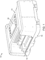
- FIGS. 1-6 depict various views of the exterior of a refrigeration control unit 100. Specifically, FIGS. 1 and 2 depict perspective views, FIG. 3 depicts a front elevation view, FIGS. 4 and 5 depict side elevation views and FIG. 6 depicts a rear elevation view.
- Refrigeration control unit 100 may be configured to control commercial refrigeration equipment, including walk-in refrigerators, coolers, and freezers installed in grocery stores, restaurants, and the like. In some embodiments, refrigeration control unit devices may also be used to control refrigeration and freezer cases for the display and distribution of food service products.
- refrigeration control unit 100 may include, among other components, a first enclosure component 102, a universal serial bus (USB) port 104, a second enclosure component 106, and a user interface component 108.
- the user interface component 108 includes a display and unit controls which are described in further detail below with reference to FIGS. 20 and 21 .
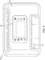
- FIG. 3 a front elevation view of the refrigeration control unit 100 is depicted.
- the refrigeration control unit 100 is shown to include a USB port 104 that may enable a cloning feature of user-configurable parameters of the refrigeration control unit 100.
- a user or technician configuring the parameters of one refrigeration control unit may wish to utilize the same parameters across all refrigeration control units utilized in a facility.
- the cloning process may begin with the user selecting and/or configuring all desired parameters on the first refrigeration control unit 100.
- Example refrigeration unit parameters and their possible values are included below in Table 1.
- possible parameters configurable by a user may include, but are not limited to, unit display parameters, user interface parameters, BACnet parameters, sensor parameters, and defrost process parameters.
- the user may insert a flash drive or other type of removable storage into the USB port 104 and may export a configuration file containing all desired parameters and parameter values to the flash drive or removable storage.
- Table 1 Example Refrigeration Control Unit Parameters and Parameter Values Parameter Parameter Values Units Fahrenheit / Celsius Backlight Intensity Display brightness level System Name User assigned Time Format 12 / 24 hour display Date Format Month-Day-Year, Day-Month-Year Auto Daylight Savings Time Automatically adjust for DST (enable / disable) BACnet Adress Network address BACnet ID Network Object ID BACnet Baud Communication baud rate Precision Superheat Control Installed - Yes / No Sensor Type Sensor type, A99 or NTC Sensor Offset User adjustment, calibrate due to sensor length Sensor Measure Function - space temp or defrost termination Sensor Weight Sensor weighting Anti-short Cycle Delay Prevents excessive cycling of equipment Setpoint Target space temperature Differential Used with setpoint, establishes refrigeration On/Off points
- the USB port 104 is accessible from the exterior of the refrigeration control unit 100.
- the USB port 104 is at least partially encapsulated within the first enclosure component 102 and is accessible behind a door or dust cover.
- other methods of transferring a configuration file may be utilized, including, but not limited to, wireless communications (e.g., via Bluetooth, Wi-Fi, local area network (LAN), etc.), via cloud storage, web transfer, a transfer cable (e.g., using a SATA, eSATA, or other interface), etc.
- FIGS. 4 and 5 side elevation views of the refrigeration control unit 100 are depicted.
- the first enclosure component 102 and the second enclosure component 106 may be coupled using a snap fit process in which latching components 110 of the first enclosure component 102 fit over protrusion features 112 of the second enclosure component 106.
- the enclosure components 102 and 106 may be coupled using any suitable mechanism (e.g., fasteners, hinges).
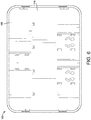
- FIG. 6 a rear elevation view of the refrigeration control unit 100 is depicted.
- second enclosure component 106 may include a DIN rail feature 114 that permits the refrigeration control unit 100 to be mounted on a DIN rail (e.g., a type of standardized metal rail widely used to mount circuit breakers and other industrial control equipment inside equipment racks).
- the DIN rail can be a top hat rail (also known as a type O, type Omega, or T35 rail), a C section rail, or a G section rail.
- the DIN rail feature 114 can include features including, but not limited to, clips, recesses, and protrusions.
- second enclosure component 106 may include any features (e.g., holes, slots) required to mount the refrigeration control unit 100 in its installation location.
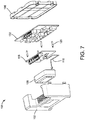
- control unit 100 includes a first enclosure component 102, a user interface component 108, a low voltage component board 118 that is coupled to user interface component 108 via wire routing 116, and a high voltage component board 122 that is coupled to the low voltage component board 118 via multiple standoffs 120.
- Control unit 100 is further shown to include a second enclosure component 106 that may be detachably coupled to the first enclosure component 102.
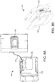
- FIG. 8A depicts the remote mounting capabilities of the refrigeration control unit 100.
- the user interface component 108 may be removed from the refrigeration control unit 100 and mounted in a different location from the remainder of the refrigeration control unit 100.
- the installation location for the control unit 100 may require both user accessibility and the ability to wash the installation location with water and/or cleaning fluid (e.g., a freezer compartment used to store food). Since the user interface component 108 may be better protected against water ingress than the rest of the refrigeration control unit 100 (e.g., the user interface component 108 may have an IP54 ingress protection rating), the user interface component 108 may be mounted separately and connected to the refrigeration control unit 100 using an accessory cable 124. In some embodiments, the length of the accessory cable 124 permits the user interface component 108 to be mounted up to 10 feet or more away from the refrigeration control unit 100. For example, in some embodiments, the accessory cable can have a length ranging from 8 feet to 12 feet.
- the opening for the user interface component 108 in the first enclosure component 102 may be covered by a cover plate accessory 126.
- FIG. 8B an exploded view of the user interface component 108 is depicted.
- the user interface component 108 When mounted remotely from the first enclosure component 102, the user interface component 108 may include a remote mounting case 128 with a gasket seal 130. Gasket seal 130 may permit the user interface component 108 to achieve an IP54 water ingress rating when the user interface component 108 is mounted in a panel opening.
- the remote mounting case 128 may include one or more selflatching design features 132 that grip the panel opening to maintain pressure on the gasket seal 130.
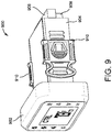
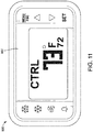
- FIGS. 9-19 another example implementation of a refrigeration control unit 900 is depicted. Specifically, FIGS. 9 and 10 depict perspective views, FIG. 11 depicts a front elevation view, FIG. 12 depicts a rear elevation view, and FIGS. 14 and 15 depict side elevation views. Similar to refrigeration control units 100, refrigeration control unit 900 is shown to include a user interface component 902. In some embodiments, user interface component 902 is identical or substantially similar to user interface component 108, described above with reference to FIGS. 1-9 . User interface component 902 may include both a display and unit controls, described in further detail below with reference to FIGS. 20 and 21 . Although smaller in form factor than refrigeration control unit 100, refrigeration control unit 900 may be configured to perform many of the same functions as refrigeration control unit 100. For example, approximately 80-90% of the firmware for refrigeration control unit 900 may be identical to the firmware of refrigeration control unit 100.
- user interface component 902 may be coupled to an electronics enclosure 904.
- Electronics enclosure 904 may be configured to house a first printed circuit board (PCB) 906 and a second PCB 908. Due to the small size of the refrigeration control unit 900, certain PCB locating features are integrated into the electronics enclosure 904 to locate the PCBs 906 and 908 relative to each other and the electronics enclosure 904. These locating features are described in further detail below with reference to FIGS. 16-19 .
- Refrigeration control unit 900 is further shown to include mounting brackets 910 on either side of the electronics enclosure 904.
- Mounting brackets 910 may be configured to couple the refrigeration control unit 900 to mounting rails and may permit easy push and pull installation motions. As shown in FIGS. 13 and 14 , mounting brackets 910 may also include ergonomic grip features 912 that provide a user with a secure hold as the user installs the refrigeration control unit 900.
- refrigeration control unit 900 is shown to include a user interface PCB 914 (the "UI PCB") housed within the user interface component 902.
- First PCB 906 and second PCB 908 may be configured to electrically couple to the user interface PCB 914 by any suitable method (e.g., board-to-board connector, cable).
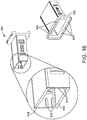
- electronics enclosure 904 may include several features configured to retain and locate the first PCB 906 and the second PCB 908.
- the features include, but are not limited to, ribs 916 which support and maintain a required separation distance between PCBs 906 and 908, and PCB stopper protrusions 918 which prevent the PCBs 906 from extending too far out of the electronics enclosure 904.
- Lock features 920 may be configured to detachably couple a front portion 922 of the electronics enclosure 904 to the user interface component 902. Recesses 924 proximate to the front portion 922 may ensure error free installation of the PCBs 906 and 908 into the electronics enclosure 904.
- Gasket seal 926 may permit the refrigeration control unit to achieve an IP54 water ingress rating when mounted into a panel cutout.
- FIGS. 20 and 21 front elevation views of a refrigeration unit control devices 100 and 900 are shown, according to some embodiments.
- user interface component 108 of refrigeration control unit device 100 and user interface component 902 of refrigeration control unit device 900 are identical or substantially similar.
- Each of the user interface components 108 and 902 is shown to include a display 2000.
- the displays 2000 may include a seven segment alphanumeric dot matrix display component 2002 combined with a standard 3-digit segmented LCD component 2004 for temperature display.
- the seven segment dot matrix display component 2002 may be configured to permit plain language information to scroll across the display in a variety of languages.
- the dot matrix display component 2002 is configured to display alarm details, as opposed to numeric alarm codes.
- the displays 2000 may also be configured to display a setpoint temperature and/or a current temperature of the refrigeration unit.
- the setpoint temperature of the unit may be 72° F, while the current temperature of the unit may be 73° F.
- user interface components 108 and 902 may include several touch screen controls 2006.
- the touch screen controls 2006 may include an overlay with eight capacitive sensor-based buttons organized in a first column 2008 and a second column 2010.
- the overlay may be pasted on the front surface of the user interface components 108 and 902 to meet IP54 water ingress standards.
- the buttons in the first column 2008 include more frequently used buttons, while the second column 2010 includes less frequently used buttons. This layout enables alarm, defrost, and fan control on direct button press.
- the touch screen controls 2006 include six capacitive sensor-based buttons and two indicators.
- the touch screen controls 2006 may include, among other controls, a MENU/ESC control, a defrost button, a down arrow control, an up arrow control, and a SET control.
- the MENU/ESC control may be configured to allow a user to navigate through a menu structure.
- both the MENU/ESC control button and the defrost button are configured to operate with a long press feature that requires a user to depress the button for a slightly longer than average time in order to avoid the accidental operation of these buttons.
- the spacing between the touch screen controls 2006 may also be configured to prevent accidental button operation.
- the touch screen controls 2006 are further shown to include an alarm button.
- the alarm button may include a multicolor lighting feature that indicates the criticality of the alarm. For example, the alarm button may be illuminated red for a more critical alarm, and yellow for a less critical alarm.
- refrigeration control unit 2200 is depicted, according to some embodiments.
- refrigeration control unit 2200 is identical or substantially similar to the refrigeration control units described above.
- Refrigeration control unit 2200 is shown to include a processing circuit 2202.
- Processing circuit 2202 can be communicably connected to USB interface 2208, display interface 2210, control interface 2212, and sensor interface 2214 such that processing circuit 2202 and the various components thereof can send and receive data via interfaces 2208-2212.
- Processing circuit 2202 may include memory 2204 and a processor 2206.
- Processor 2206 can be implemented as a general purpose processor, an application specific integrated circuit (ASIC), one or more field programmable gate arrays (FPGAs), a group of processing components, or other suitable electronic processing components.
- Memory 2204 e.g., memory, memory unit, storage device, etc.
- devices e.g., RAM, ROM, Flash memory, hard disk storage, etc.
- Memory 2204 can be or include volatile memory or non-volatile memory. Memory 2204 may include database components, object code components, script components, or any other type of information structure for supporting the various activities and information structures described in the present application. According to some embodiments, memory 2204 is communicably connected to processor 2206 via processing circuit 2202 and includes computer code for executing (e.g., by processing circuit 2202 and/or processor 2206) one or more processes described herein. In various embodiments, the processing circuit may be communicably coupled to various components of the refrigeration equipment (not shown) and control signals transmitted to the refrigeration equipment from the processing circuit 2202 may modify an operating condition of the refrigeration equipment.
- Refrigeration control unit 2200 is further shown to include a USB interface 2208, a display interface 2210, a control interface 2212, and a sensor interface 2214.
- USB interface 2208 may be communicably coupled to a USB port (e.g., USB port 104) accessible from the exterior of the refrigeration control unit 100.
- USB interface 2208 may be used to update control unit firmware. For example, as updates to the system become available, a user may obtain the updated firmware and upload it to control unit 2200 via USB interface 2208.
- USB interface 2208 may be used in a configuration setting cloning process, described above with reference to FIG. 3 .
- Display unit interface 2210 may be communicably coupled to a display (e.g., display 2000), while control interface 2212 may be communicably coupled to unit controls (e.g., touch screen controls 2006). Based on data received from the unit controls via the control interface 2212, the processing circuit 2202 may execute processes and output data (e.g., selected refrigeration unit parameters) that are displayed on the unit display 2210.
- a display e.g., display 2000
- unit controls e.g., touch screen controls 2006
- the processing circuit 2202 may execute processes and output data (e.g., selected refrigeration unit parameters) that are displayed on the unit display 2210.
- Refrigeration control unit 2200 is further shown to include a sensor interface 2214.
- Sensor interface 2214 may be configured to receive input data from one or more sensors (e.g., temperature sensors).
- processing circuit 2202 may be configured to utilize a weighted average for process control (e.g., the processing circuit 2202 may transmit commands to modifying an operating condition of the refrigeration control unit 2200 based on the weighted average). For example, temperatures might vary across a freezer compartment (e.g., in an evaporator defrosting process, ice might melt at different rates), and a user may choose to weight a first temperature sensor at 25% of the temperature average and a second sensor at 75% of the temperature average. In some embodiments, the user selects a weight for each sensor using the touch screen controls of the refrigeration control unit.
- the elements and assemblies may be constructed from any of a wide variety of materials that provide sufficient strength or durability, in any of a wide variety of colors, textures, and combinations. Further, elements shown as integrally formed may be constructed of multiple parts or elements.
- the word "exemplary” is used to mean serving as an example, instance or illustration. Any implementation or design described herein as "exemplary” is not necessarily to be construed as preferred or advantageous over other implementations or designs. Rather, use of the word exemplary is intended to present concepts in a concrete manner. Accordingly, all such modifications are intended to be included within the scope of the present disclosure. Other substitutions, modifications, changes, and omissions may be made in the design, operating conditions, and arrangement of the preferred and other exemplary implementations without departing from the scope of the appended claims.
- Coupled means the joining of two members directly or indirectly to one another. Such joining may be stationary in nature or moveable in nature and/or such joining may allow for the flow of fluids, electricity, electrical signals, or other types of signals or communication between the two members.
- Such joining may be achieved with the two members or the two members and any additional intermediate members being integrally formed as a single unitary body with one another or with the two members or the two members and any additional intermediate members being attached to one another.
- Such joining may be permanent in nature or alternatively may be removable or releasable in nature.
- the present disclosure contemplates methods, systems and program products on any machine-readable media for accomplishing various operations.
- the embodiments of the present disclosure may be implemented using existing computer processors, or by a special purpose computer processor for an appropriate system, incorporated for this or another purpose, or by a hardwired system.
- Embodiments within the scope of the present disclosure include program products comprising machine-readable media for carrying or having machine-executable instructions or data structures stored thereon.
- Such machine-readable media can be any available media that can be accessed by a general purpose or special purpose computer or other machine with a processor.
- machine-readable media can comprise RAM, ROM, EPROM, EEPROM, CD-ROM or other optical disk storage, magnetic disk storage or other magnetic storage devices, or any other medium which can be used to carry or store desired program code in the form of machine-executable instructions or data structures and which can be accessed by a general purpose or special purpose computer or other machine with a processor.
- Machine-executable instructions include, for example, instructions and data which cause a general purpose computer, special purpose computer, or special purpose processing machines to perform a certain function or group of functions.
Landscapes
- Engineering & Computer Science (AREA)
- Chemical & Material Sciences (AREA)
- Combustion & Propulsion (AREA)
- Physics & Mathematics (AREA)
- Mechanical Engineering (AREA)
- Thermal Sciences (AREA)
- General Engineering & Computer Science (AREA)
- Devices That Are Associated With Refrigeration Equipment (AREA)
Abstract
A refrigeration control unit configured to modify an operating condition of a refrigeration unit is provided. The refrigeration control unit includes a first device housing component and a second device housing component defining a main refrigeration control device. The refrigeration control unit further includes a user interface component. The user interface component includes multiple controls configured to permit selection of multiple refrigeration unit operating parameters and a display. The user interface component is configured to be detachably coupled to the main refrigeration control device such that the user interface component is operational both when mounted in the main refrigeration control device and when mounted at a location remote to the main refrigeration control device.
Description
- This application claims the benefit of and priority to
U.S. Provisional Patent Application No. 62/665,964 filed May 2, 2018 U.S. Patent Application No. 16/252,536 filed January 18, 2019 - Refrigeration control units may be used to control commercial refrigeration equipment, including walk-in refrigerators, coolers, and freezers installed in grocery stores, restaurants, and the like. In some cases, refrigeration control units may also be used to control refrigeration and freezer cases for the display and distribution of food service products. A refrigeration control unit with improved mounting and user interface features would be useful.
- One implementation of the present disclosure is a refrigeration control unit configured to modify an operating condition of a refrigeration unit. The refrigeration control unit includes a first device housing component and a second device housing component defining a main refrigeration control device. The refrigeration control unit further includes a user interface component. The user interface component includes controls configured to permit selection of multiple refrigeration unit operating parameters and a display. The user interface component is configured to be detachably coupled to the main refrigeration control device such that the user interface component is operational both when mounted in the main refrigeration control device and when mounted at a location remote to the main refrigeration control device.
- In some embodiments, the user interface component is electrically coupled to the main refrigeration control device using an accessory cable. In other embodiments, the accessory cable has a length ranging from 8 feet to 12 feet.
- In some embodiments, the user interface component has an IP54 ingress protection rating.
- In some embodiments, the controls include capacitive sensor-based buttons.
- In some embodiments, the main refrigeration control device further includes a low voltage component circuit board and a high voltage component circuit board.
- In some embodiments, the second device housing component includes features configured to permit the refrigeration control unit to mount to a DIN rail.
- In some embodiments, the first device housing component and the second device housing component are coupled using a snap fit assembly process.
- In some embodiments, the refrigeration unit is a walk-in refrigerator, a cooler, or a freezer case.
- Another implementation of the present disclosure is refrigeration control unit configured to modify an operating condition of a refrigeration unit. The refrigeration control unit includes a first device housing component, a second device housing component, and multiple controls configured to permit selection of multiple parameter values for multiple refrigeration unit operating parameters. The refrigeration control unit further includes a processing circuit communicably coupled to the controls and multiple sensors. The processing circuit is configured to receive sensor measurements from the sensors, receive a command from the controls to assign a sensor weight to each of the sensor measurements, calculate a weighted average from the sensor measurements, and transmit a command to modify an operating condition of the refrigeration unit based on the weighted average.
- In some embodiments, the sensors include temperature sensors.
- In some embodiments, the controls include capacitive sensor-based buttons.
- In some embodiments, the refrigeration unit operating parameters include at least one of a temperature unit, a backlight intensity, a system name, a time format, a date format, and an alarm setting.
- In some embodiments, the refrigeration unit operating parameters include defrost parameters including at least one of a defrost type, a defrost termination type, a defrost duration, a number of defrosts performed per 24 hour period, and a defrost schedule.
- In some embodiments, the refrigeration unit operating parameters include sensor parameters including at least one of a sensor type, a sensor offset, a sensor measurement function, and a sensor weight.
- In some embodiments, the processing circuit is further configured to receive a command from the controls to create a configuration file. The configuration file includes refrigeration unit operating parameters and parameter values. The processing circuit is further configured to export the configuration file to a removable storage device. The removable storage device is communicably coupled to a universal serial bus (USB) port of the refrigeration control unit.
- In some embodiments, the refrigeration unit is a walk-in refrigerator, a cooler, or a freezer case.
- Yet another implementation of the present disclosure is a method of operating a refrigeration unit using a refrigeration control unit. The method includes receiving sensor measurements from multiple sensors, receiving a command from controls to assign a sensor weight to each of the sensor measurements, calculating a weighted average from the sensor measurements, and transmitting a command to modify an operating condition of the refrigeration unit based on the weighted average.
- In some embodiments, the sensors measurements include temperature measurements.
- In some embodiments, the method further includes receiving a command from the controls to create a configuration file. The configuration file includes refrigeration unit operating parameters and parameter values. The method further includes exporting the configuration file to a removable storage device. The removable storage device is communicably coupled to a universal serial bus (USB) port of the refrigeration control unit.
- Those skilled in the art will appreciate that the summary is illustrative only and is not intended to be in any way limiting. Other aspects, inventive features, and advantages of the devices and/or processes described herein, as defined solely by the claims, will become apparent in the detailed description set forth herein and taken in conjunction with the accompanying drawings.
-
- FIG. 1
- is a perspective view of a refrigeration control unit, according to some embodiments.
- FIG. 2
- is another perspective view of the refrigeration control unit of
FIG. 1 , according to some embodiments. - FIG. 3
- is a front elevation view of the refrigeration control unit of
FIG. 1 , according to some embodiments. - FIG. 4
- is a side elevation view of the refrigeration control unit of
FIG. 1 , according to some embodiments. - FIG. 5
- is another side elevation view of the refrigeration control unit of
FIG. 1 , according to some embodiments. - FIG. 6
- is a rear elevation view of the refrigeration control unit of
FIG. 1 , according to some embodiments. - FIG. 7
- is an exploded view of the refrigeration control unit of
FIG. 1 , according to some embodiments. - FIG. 8A
- is a perspective view of the remote mounting feature of the refrigeration control unit of
FIG. 1 , according to some embodiments. - FIG. 8B
- is an exploded perspective view of the user interface component, according to some embodiments.
- FIG. 9
- is a perspective view of another refrigeration control unit, according to some embodiments.
- FIG. 10
- is another perspective view of the refrigeration control unit of
FIG. 9 , according to some embodiments. - FIG. 11
- is a front elevation view of the refrigeration control unit of
FIG. 9 , according to some embodiments. - FIG. 12
- is a rear elevation view of the refrigeration control unit of
FIG. 9 , according to some embodiments. - FIG. 13
- is a side elevation view of the refrigeration control unit of
FIG. 9 , according to some embodiments. - FIG. 14
- is another side elevation view of the refrigeration control unit of
FIG. 9 , according to some embodiments. - FIG. 15
- is a perspective view of the internal components of the refrigeration control unit of
FIG. 9 , according to some embodiments. - FIG. 16
- is a perspective view of electronics enclosure mounting features of the refrigeration control unit of
FIG. 9 , according to some embodiments. - FIG. 17
- is an exploded view of the refrigeration control unit of
FIG. 9 , according to some embodiments. - FIG. 18
- is another perspective view of electronics enclosure mounting features of the refrigeration control unit of
FIG. 9 , according to some embodiments. - FIG. 19
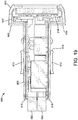
- is a sectional view of the refrigeration control unit of
FIG. 9 , according to some embodiments. - FIG. 20
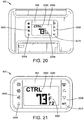
- is a front elevation view of the refrigeration control unit of
FIG. 1 , according to some embodiments. - FIG. 21
- is a front elevation view of the refrigeration control unit of
FIG. 9 , according to some embodiments. - FIG. 22
- is a block diagram of a refrigeration control unit, according to some embodiments.
- Referring generally to FIGURES, disclosed herein are various embodiments related to a refrigeration control unit.
FIGS. 1-6 depict various views of the exterior of arefrigeration control unit 100. Specifically,FIGS. 1 and2 depict perspective views,FIG. 3 depicts a front elevation view,FIGS. 4 and 5 depict side elevation views andFIG. 6 depicts a rear elevation view.Refrigeration control unit 100 may be configured to control commercial refrigeration equipment, including walk-in refrigerators, coolers, and freezers installed in grocery stores, restaurants, and the like. In some embodiments, refrigeration control unit devices may also be used to control refrigeration and freezer cases for the display and distribution of food service products. As shown,refrigeration control unit 100 may include, among other components, afirst enclosure component 102, a universal serial bus (USB)port 104, asecond enclosure component 106, and auser interface component 108. Theuser interface component 108 includes a display and unit controls which are described in further detail below with reference toFIGS. 20 and 21 . - Referring specifically to
FIG. 3 , a front elevation view of therefrigeration control unit 100 is depicted. Therefrigeration control unit 100 is shown to include aUSB port 104 that may enable a cloning feature of user-configurable parameters of therefrigeration control unit 100. - For example, in some embodiments, a user or technician configuring the parameters of one refrigeration control unit may wish to utilize the same parameters across all refrigeration control units utilized in a facility. The cloning process may begin with the user selecting and/or configuring all desired parameters on the first
refrigeration control unit 100. Example refrigeration unit parameters and their possible values are included below in Table 1. As shown, possible parameters configurable by a user may include, but are not limited to, unit display parameters, user interface parameters, BACnet parameters, sensor parameters, and defrost process parameters. After the user has selected and/or configured all desired parameters, the user may insert a flash drive or other type of removable storage into theUSB port 104 and may export a configuration file containing all desired parameters and parameter values to the flash drive or removable storage. The cloning process concludes as the user inserts the flash drive or removable storage into theUSB ports 104 of all additionalrefrigeration control units 100 and imports the configuration file into the processing circuits of the additional refrigeration control units utilized in the facility.Table 1: Example Refrigeration Control Unit Parameters and Parameter Values Parameter Parameter Values Units Fahrenheit / Celsius Backlight Intensity Display brightness level System Name User assigned Time Format 12 / 24 hour display Date Format Month-Day-Year, Day-Month-Year Auto Daylight Savings Time Automatically adjust for DST (enable / disable) BACnet Adress Network address BACnet ID Network Object ID BACnet Baud Communication baud rate Precision Superheat Control Installed - Yes / No Sensor Type Sensor type, A99 or NTC Sensor Offset User adjustment, calibrate due to sensor length Sensor Measure Function - space temp or defrost termination Sensor Weight Sensor weighting Anti-short Cycle Delay Prevents excessive cycling of equipment Setpoint Target space temperature Differential Used with setpoint, establishes refrigeration On/Off points Sensor Failure Mode Upon sensor failure - refrigeration On, Off, or Cycle Defrost Type Passive, Electric Heat, Hot Gas Defrost Termination Type Time Sensor Defrost Duration Defrost interval, minutes Drip Time Drip interval, allow water to drip off evaporator minutes Defrosts per Day Number of defrosts performed per 24 hour period Defrost Evenly Evenly spaced defrosts (in time) - Yes / No Defrost Schedule List of defrost start times Defrost Algorithm Scheduled or Adaptive Adaptive Defrost Interval Time between defrosts Adaptive - Max Defrost Interval Maximum amount of time between defrosts Adaptive - Min Defrost Interval Minimum amount of time between defrosts Adaptive - Start of Blackout Time of day when the blackout period begins (no defrosts allowed) Adaptive - Blackout Duration Length of blackout period Binary Input Mode, Active State, Action, and Action Delay Alarm Setting Enabled, Threshold, Delay, Re-alarm interval - In some embodiments, as shown in
FIG. 3 , theUSB port 104 is accessible from the exterior of therefrigeration control unit 100. In other embodiments, theUSB port 104 is at least partially encapsulated within thefirst enclosure component 102 and is accessible behind a door or dust cover. In yet further embodiments, rather than or in addition to utilizing a flash drive for cloning, other methods of transferring a configuration file may be utilized, including, but not limited to, wireless communications (e.g., via Bluetooth, Wi-Fi, local area network (LAN), etc.), via cloud storage, web transfer, a transfer cable (e.g., using a SATA, eSATA, or other interface), etc. - Referring now to
FIGS. 4 and 5 , side elevation views of therefrigeration control unit 100 are depicted. As shown, in one embodiment, thefirst enclosure component 102 and thesecond enclosure component 106 may be coupled using a snap fit process in which latchingcomponents 110 of thefirst enclosure component 102 fit over protrusion features 112 of thesecond enclosure component 106. In other embodiments, theenclosure components FIG. 6 , a rear elevation view of therefrigeration control unit 100 is depicted. As shown,second enclosure component 106 may include aDIN rail feature 114 that permits therefrigeration control unit 100 to be mounted on a DIN rail (e.g., a type of standardized metal rail widely used to mount circuit breakers and other industrial control equipment inside equipment racks). In various embodiments, the DIN rail can be a top hat rail (also known as a type O, type Omega, or T35 rail), a C section rail, or a G section rail. For example, theDIN rail feature 114 can include features including, but not limited to, clips, recesses, and protrusions. In other embodiments,second enclosure component 106 may include any features (e.g., holes, slots) required to mount therefrigeration control unit 100 in its installation location. - Turning now to
FIG. 7 , an exploded view of therefrigeration control unit 100 is depicted. As shown,control unit 100 includes afirst enclosure component 102, auser interface component 108, a lowvoltage component board 118 that is coupled touser interface component 108 viawire routing 116, and a highvoltage component board 122 that is coupled to the lowvoltage component board 118 viamultiple standoffs 120.Control unit 100 is further shown to include asecond enclosure component 106 that may be detachably coupled to thefirst enclosure component 102. -
FIG. 8A depicts the remote mounting capabilities of therefrigeration control unit 100. - As shown, the
user interface component 108 may be removed from therefrigeration control unit 100 and mounted in a different location from the remainder of therefrigeration control unit 100. - For example, in some embodiments, the installation location for the
control unit 100 may require both user accessibility and the ability to wash the installation location with water and/or cleaning fluid (e.g., a freezer compartment used to store food). Since theuser interface component 108 may be better protected against water ingress than the rest of the refrigeration control unit 100 (e.g., theuser interface component 108 may have an IP54 ingress protection rating), theuser interface component 108 may be mounted separately and connected to therefrigeration control unit 100 using anaccessory cable 124. In some embodiments, the length of theaccessory cable 124 permits theuser interface component 108 to be mounted up to 10 feet or more away from therefrigeration control unit 100. For example, in some embodiments, the accessory cable can have a length ranging from 8 feet to 12 feet. In some embodiments, when theuser interface component 108 is mounted remotely, the opening for theuser interface component 108 in thefirst enclosure component 102 may be covered by acover plate accessory 126. Referring toFIG. 8B , an exploded view of theuser interface component 108 is depicted. When mounted remotely from thefirst enclosure component 102, theuser interface component 108 may include aremote mounting case 128 with agasket seal 130.Gasket seal 130 may permit theuser interface component 108 to achieve an IP54 water ingress rating when theuser interface component 108 is mounted in a panel opening. Theremote mounting case 128 may include one or more selflatching design features 132 that grip the panel opening to maintain pressure on thegasket seal 130. - Referring now to
FIGS. 9-19 , another example implementation of arefrigeration control unit 900 is depicted. Specifically,FIGS. 9 and10 depict perspective views,FIG. 11 depicts a front elevation view,FIG. 12 depicts a rear elevation view, andFIGS. 14 and15 depict side elevation views. Similar torefrigeration control units 100,refrigeration control unit 900 is shown to include auser interface component 902. In some embodiments,user interface component 902 is identical or substantially similar touser interface component 108, described above with reference toFIGS. 1-9 .User interface component 902 may include both a display and unit controls, described in further detail below with reference toFIGS. 20 and 21 . Although smaller in form factor thanrefrigeration control unit 100,refrigeration control unit 900 may be configured to perform many of the same functions asrefrigeration control unit 100. For example, approximately 80-90% of the firmware forrefrigeration control unit 900 may be identical to the firmware ofrefrigeration control unit 100. - As shown,
user interface component 902 may be coupled to anelectronics enclosure 904.Electronics enclosure 904 may be configured to house a first printed circuit board (PCB) 906 and asecond PCB 908. Due to the small size of therefrigeration control unit 900, certain PCB locating features are integrated into theelectronics enclosure 904 to locate thePCBs electronics enclosure 904. These locating features are described in further detail below with reference toFIGS. 16-19 .Refrigeration control unit 900 is further shown to include mountingbrackets 910 on either side of theelectronics enclosure 904. - Mounting
brackets 910 may be configured to couple therefrigeration control unit 900 to mounting rails and may permit easy push and pull installation motions. As shown inFIGS. 13 and 14 , mountingbrackets 910 may also include ergonomic grip features 912 that provide a user with a secure hold as the user installs therefrigeration control unit 900. - Turning now to
FIG. 15 , a perspective view of the internal components of therefrigeration control unit 900 are depicted. In addition to thefirst PCB 906 and thesecond PCB 908 housed insideelectronics enclosure 904,refrigeration control unit 900 is shown to include a user interface PCB 914 (the "UI PCB") housed within theuser interface component 902.First PCB 906 andsecond PCB 908 may be configured to electrically couple to theuser interface PCB 914 by any suitable method (e.g., board-to-board connector, cable). - Referring now to
FIGS. 16-19 , as described above,electronics enclosure 904 may include several features configured to retain and locate thefirst PCB 906 and thesecond PCB 908. The features include, but are not limited to,ribs 916 which support and maintain a required separation distance betweenPCBs PCB stopper protrusions 918 which prevent thePCBs 906 from extending too far out of theelectronics enclosure 904. Lock features 920 may be configured to detachably couple afront portion 922 of theelectronics enclosure 904 to theuser interface component 902.Recesses 924 proximate to thefront portion 922 may ensure error free installation of thePCBs electronics enclosure 904.Gasket seal 926 may permit the refrigeration control unit to achieve an IP54 water ingress rating when mounted into a panel cutout. - Turning now to
FIGS. 20 and 21 , front elevation views of a refrigerationunit control devices user interface component 108 of refrigerationcontrol unit device 100 anduser interface component 902 of refrigerationcontrol unit device 900 are identical or substantially similar. Each of theuser interface components display 2000. Thedisplays 2000 may include a seven segment alphanumeric dotmatrix display component 2002 combined with a standard 3-digitsegmented LCD component 2004 for temperature display. The seven segment dotmatrix display component 2002 may be configured to permit plain language information to scroll across the display in a variety of languages. In some embodiments, the dotmatrix display component 2002 is configured to display alarm details, as opposed to numeric alarm codes. This feature allows all possible alarms to be displayed with specific details, which leads to easier and faster troubleshooting. In addition to the scrolling parameter portion, thedisplays 2000 may also be configured to display a setpoint temperature and/or a current temperature of the refrigeration unit. For example, as shown inFIGS. 20 and 21 , the setpoint temperature of the unit may be 72° F, while the current temperature of the unit may be 73° F. - In addition to the
displays 2000,user interface components first column 2008 and asecond column 2010. The overlay may be pasted on the front surface of theuser interface components first column 2008 include more frequently used buttons, while thesecond column 2010 includes less frequently used buttons. This layout enables alarm, defrost, and fan control on direct button press. In an alternative embodiment, the touch screen controls 2006 include six capacitive sensor-based buttons and two indicators. - In various embodiments, the touch screen controls 2006 may include, among other controls, a MENU/ESC control, a defrost button, a down arrow control, an up arrow control, and a SET control. The MENU/ESC control may be configured to allow a user to navigate through a menu structure. In some embodiments, both the MENU/ESC control button and the defrost button are configured to operate with a long press feature that requires a user to depress the button for a slightly longer than average time in order to avoid the accidental operation of these buttons. The spacing between the touch screen controls 2006 may also be configured to prevent accidental button operation. The touch screen controls 2006 are further shown to include an alarm button. The alarm button may include a multicolor lighting feature that indicates the criticality of the alarm. For example, the alarm button may be illuminated red for a more critical alarm, and yellow for a less critical alarm.
- Referring now to
FIG. 22 , a block diagram of arefrigeration control unit 2200 is depicted, according to some embodiments. In various embodiments,refrigeration control unit 2200 is identical or substantially similar to the refrigeration control units described above. -
Refrigeration control unit 2200 is shown to include aprocessing circuit 2202.Processing circuit 2202 can be communicably connected toUSB interface 2208,display interface 2210,control interface 2212, andsensor interface 2214 such thatprocessing circuit 2202 and the various components thereof can send and receive data via interfaces 2208-2212. -
Processing circuit 2202 may includememory 2204 and aprocessor 2206.Processor 2206 can be implemented as a general purpose processor, an application specific integrated circuit (ASIC), one or more field programmable gate arrays (FPGAs), a group of processing components, or other suitable electronic processing components. Memory 2204 (e.g., memory, memory unit, storage device, etc.) may include one or more devices (e.g., RAM, ROM, Flash memory, hard disk storage, etc.) for storing data and/or computer code for completing or facilitating the various processes, layers and modules described in the present application. -
Memory 2204 can be or include volatile memory or non-volatile memory.Memory 2204 may include database components, object code components, script components, or any other type of information structure for supporting the various activities and information structures described in the present application. According to some embodiments,memory 2204 is communicably connected toprocessor 2206 viaprocessing circuit 2202 and includes computer code for executing (e.g., by processingcircuit 2202 and/or processor 2206) one or more processes described herein. In various embodiments, the processing circuit may be communicably coupled to various components of the refrigeration equipment (not shown) and control signals transmitted to the refrigeration equipment from theprocessing circuit 2202 may modify an operating condition of the refrigeration equipment. -
Refrigeration control unit 2200 is further shown to include aUSB interface 2208, adisplay interface 2210, acontrol interface 2212, and asensor interface 2214.USB interface 2208 may be communicably coupled to a USB port (e.g., USB port 104) accessible from the exterior of therefrigeration control unit 100. In some embodiments,USB interface 2208 may be used to update control unit firmware. For example, as updates to the system become available, a user may obtain the updated firmware and upload it to controlunit 2200 viaUSB interface 2208. - In still further embodiments,
USB interface 2208 may be used in a configuration setting cloning process, described above with reference toFIG. 3 . -
Display unit interface 2210 may be communicably coupled to a display (e.g., display 2000), whilecontrol interface 2212 may be communicably coupled to unit controls (e.g., touch screen controls 2006). Based on data received from the unit controls via thecontrol interface 2212, theprocessing circuit 2202 may execute processes and output data (e.g., selected refrigeration unit parameters) that are displayed on theunit display 2210. -
Refrigeration control unit 2200 is further shown to include asensor interface 2214. -
Sensor interface 2214 may be configured to receive input data from one or more sensors (e.g., temperature sensors). When multiple sensors are connected tosensor interface 2214,processing circuit 2202 may be configured to utilize a weighted average for process control (e.g., theprocessing circuit 2202 may transmit commands to modifying an operating condition of therefrigeration control unit 2200 based on the weighted average). For example, temperatures might vary across a freezer compartment (e.g., in an evaporator defrosting process, ice might melt at different rates), and a user may choose to weight a first temperature sensor at 25% of the temperature average and a second sensor at 75% of the temperature average. In some embodiments, the user selects a weight for each sensor using the touch screen controls of the refrigeration control unit. The equation for obtaining the weighted average may be as follows:
- Therefore, if the first temperature sensor reports a temperature of 100 °F and the second sensor reports a temperature of 90 °F, the weighted average may be obtained as follows:

- Numerous specific details are described to provide a thorough understanding of the disclosure. However, in certain instances, well-known or conventional details are not described in order to avoid obscuring the description. References to "some embodiments," "one embodiment," "an exemplary embodiment," and/or "various embodiments" in the present disclosure can be, but not necessarily are, references to the same embodiment and such references mean at least one of the embodiments.
- Alternative language and synonyms may be used for any one or more of the terms discussed herein. No special significance should be placed upon whether or not a term is elaborated or discussed herein. Synonyms for certain terms are provided. A recital of one or more synonyms does not exclude the use of other synonyms. The use of examples anywhere in this specification including examples of any terms discussed herein is illustrative only, and is not intended to further limit the scope and meaning of the disclosure or of any exemplified term.
- Likewise, the disclosure is not limited to various embodiments given in this specifi cation.
- The elements and assemblies may be constructed from any of a wide variety of materials that provide sufficient strength or durability, in any of a wide variety of colors, textures, and combinations. Further, elements shown as integrally formed may be constructed of multiple parts or elements.
- As used herein, the word "exemplary" is used to mean serving as an example, instance or illustration. Any implementation or design described herein as "exemplary" is not necessarily to be construed as preferred or advantageous over other implementations or designs. Rather, use of the word exemplary is intended to present concepts in a concrete manner. Accordingly, all such modifications are intended to be included within the scope of the present disclosure. Other substitutions, modifications, changes, and omissions may be made in the design, operating conditions, and arrangement of the preferred and other exemplary implementations without departing from the scope of the appended claims.
- As used herein, the terms "approximately," "about," "substantially," and similar terms are intended to have a broad meaning in harmony with the common and accepted usage by those of ordinary skill in the art to which the subject matter of this disclosure pertains. It should be understood by those of skill in the art who review this disclosure that these terms are intended to allow a description of certain features described and claimed without restricting the scope of these features to the precise numerical ranges provided. Accordingly, these terms should be interpreted as indicating that insubstantial or inconsequential modifications or alterations of the subject matter described and claimed are considered to be within the scope of the invention as recited in the appended claims.
- As used herein, the term "coupled" means the joining of two members directly or indirectly to one another. Such joining may be stationary in nature or moveable in nature and/or such joining may allow for the flow of fluids, electricity, electrical signals, or other types of signals or communication between the two members.
- Such joining may be achieved with the two members or the two members and any additional intermediate members being integrally formed as a single unitary body with one another or with the two members or the two members and any additional intermediate members being attached to one another. Such joining may be permanent in nature or alternatively may be removable or releasable in nature.
- Although only a few embodiments have been described in detail in this disclosure, many modifications are possible (e.g., variations in sizes, dimensions, structures, shapes and proportions of the various elements, values of parameters, mounting arrangements, use of materials, colors, orientations, etc.). For example, the position of elements may be reversed or otherwise varied and the nature or number of discrete elements or positions may be altered or varied. Accordingly, all such modifications are intended to be included within the scope of the present disclosure. Other substitutions, modifications, changes, and omissions may be made in the design, operating conditions and arrangement of the exemplary embodiments without departing from the scope of the present disclosure.
- The present disclosure contemplates methods, systems and program products on any machine-readable media for accomplishing various operations. The embodiments of the present disclosure may be implemented using existing computer processors, or by a special purpose computer processor for an appropriate system, incorporated for this or another purpose, or by a hardwired system. Embodiments within the scope of the present disclosure include program products comprising machine-readable media for carrying or having machine-executable instructions or data structures stored thereon. Such machine-readable media can be any available media that can be accessed by a general purpose or special purpose computer or other machine with a processor. By way of example, such machine-readable media can comprise RAM, ROM, EPROM, EEPROM, CD-ROM or other optical disk storage, magnetic disk storage or other magnetic storage devices, or any other medium which can be used to carry or store desired program code in the form of machine-executable instructions or data structures and which can be accessed by a general purpose or special purpose computer or other machine with a processor.
- When information is transferred or provided over a network or another communications connection (either hardwired, wireless, or a combination of hardwired or wireless) to a machine, the machine properly views the connection as a machine-readable medium. Thus, any such connection is properly termed a machine-readable medium. Combinations of the above are also included within the scope of machine-readable media. Machine-executable instructions include, for example, instructions and data which cause a general purpose computer, special purpose computer, or special purpose processing machines to perform a certain function or group of functions.
- Although the figures may show a specific order of method steps, the order of the steps may differ from what is depicted. Also, two or more steps may be performed concurrently or with partial concurrence. Such variation will depend on the software and hardware systems chosen and on designer choice. All such variations are within the scope of the disclosure.
- Likewise, software implementations could be accomplished with standard programming techniques with rule based logic and other logic to accomplish the various connection steps, processing steps, comparison steps and decision steps.
Claims (15)
- A refrigeration control unit configured to modify an operating condition of a refrigeration unit, comprising:- a first device housing component;- a second device housing component, the first device housing component and the second device housing component defining a main refrigeration control device; and- a user interface component, comprising:wherein the user interface component is configured to be detachably coupled to the main refrigeration control device such that the user interface component is operational both when mounted in the main refrigeration control device and when mounted at a location remote to the main refrigeration control device.- a plurality of controls configured to permit selection of a plurality of refrigeration unit operating parameters; and- a display;
- The refrigeration control unit of claim 1,
wherein the user interface component is electrically coupled to the main refrigeration control device using an accessory cable. - The refrigeration control unit of claim 2,
wherein the accessory cable has a length ranging from 8 feet to 12 feet. - The refrigeration control unit of one of claims 1 to 3,
wherein the user interface component has an IP54 ingress protection rating. - The refrigeration control unit of one of claims 1 to 4,
wherein the plurality of controls comprise capacitive sensor-based buttons. - The refrigeration control unit of one of claims 1 to 5,
wherein the main refrigeration control device further comprises a low voltage component circuit board and a high voltage component circuit board. - The refrigeration control unit of one of claims 1 to 6,
wherein the second device housing component comprises a plurality of features configured to permit the refrigeration control unit to mount to a DIN rail. - The refrigeration control unit of one of claims 1 to 7,
wherein the first device housing component and the second device housing component are coupled using a snap fit assembly process. - The refrigeration control unit of one of claims 1 to 8,
wherein the refrigeration unit is at least one of a walk-in refrigerator, a cooler, and a freezer case. - The refrigeration control unit of one of claims 1 to 9,
wherein the plurality of refrigeration unit operating parameters comprises at least one of a temperature unit, a backlight intensity, a system name, a time format, a date format, and an alarm setting. - The refrigeration control unit of one of claims 1 to 10,
wherein the plurality of refrigeration unit operating parameters comprise defrost parameters including at least one of a defrost type, a defrost termination type, a defrost duration, a number of defrosts performed per 24 hour period, and a defrost schedule. - The refrigeration control unit of one of claims 1 to 11, further comprising:- a processing circuit communicably coupled to the plurality of controls and a plurality of sensors, the processing circuit configured to:- receive a plurality of sensor measurements from the plurality of sensors;- receive a command from the plurality of controls to assign a sensor weight to each of the plurality of sensor measurements;- calculate a weighted average from the plurality of sensor measurements; and- transmit a command to modify an operating condition of the refrigeration unit based at least in part on the weighted average.
- The refrigeration control unit of claim 12,
wherein the plurality of sensors comprise temperature sensors. - The refrigeration control unit of claim 12 or 13,
wherein the plurality of refrigeration unit operating parameters comprise sensor parameters including at least one of a sensor type, a sensor offset, a sensor measurement function, and a sensor weight. - The refrigeration control unit of one of claims 12 to 14,
wherein the processing circuit is further configured to:- receive a command from the plurality of controls to create a configuration file, the configuration file comprising the plurality of refrigeration unit operating parameters and the plurality of parameter values; and- export the configuration file to a removable storage device, the removable storage device communicably coupled to a universal serial bus (USB) port of the refrigeration control unit.
Applications Claiming Priority (2)
| Application Number | Priority Date | Filing Date | Title |
|---|---|---|---|
| US201862665964P | 2018-05-02 | 2018-05-02 | |
| US16/252,536 US20190226756A1 (en) | 2018-01-19 | 2019-01-18 | Refrigeration control unit |
Publications (1)
| Publication Number | Publication Date |
|---|---|
| EP3564607A1 true EP3564607A1 (en) | 2019-11-06 |
Family
ID=66379763
Family Applications (1)
| Application Number | Title | Priority Date | Filing Date |
|---|---|---|---|
| EP19172230.5A Withdrawn EP3564607A1 (en) | 2018-05-02 | 2019-05-02 | Refrigeration control unit |
Country Status (2)
| Country | Link |
|---|---|
| EP (1) | EP3564607A1 (en) |
| CN (1) | CN110440520A (en) |
Families Citing this family (1)
| Publication number | Priority date | Publication date | Assignee | Title |
|---|---|---|---|---|
| CN111811203B (en) * | 2020-07-20 | 2022-03-18 | 青岛合启立智能科技有限公司 | Refrigeration transfer device control system and control method |
Citations (6)
| Publication number | Priority date | Publication date | Assignee | Title |
|---|---|---|---|---|
| WO2005047786A1 (en) * | 2003-11-14 | 2005-05-26 | Lg Electronics Inc. | Refrigerator |
| US20080164226A1 (en) * | 2007-01-04 | 2008-07-10 | Whirlpool Corporation | Alternative Hosts for Multiple Adapters and Multiple Consumer Electronic Devices |
| WO2008086136A2 (en) * | 2007-01-04 | 2008-07-17 | Whirpool Corporation | Adapter and consumer electronic device functional unit |
| US20090090127A1 (en) * | 2007-10-08 | 2009-04-09 | Do Joon Young | Refrigerator |
| EP2910877A1 (en) * | 2012-10-12 | 2015-08-26 | Kabushiki Kaisha Toshiba | Refrigerator |
| WO2017161324A1 (en) * | 2016-03-17 | 2017-09-21 | Fresh Chill Solutions, Inc. | Methods, apparatuses, and systems for cooling |
Family Cites Families (5)
| Publication number | Priority date | Publication date | Assignee | Title |
|---|---|---|---|---|
| JP3404224B2 (en) * | 1996-08-07 | 2003-05-06 | 松下冷機株式会社 | Refrigerator temperature controller |
| CN101898658A (en) * | 2009-05-30 | 2010-12-01 | 邢刚 | High-precision and constant temperature and humidity cabinet |
| CN103049013B (en) * | 2011-10-13 | 2015-02-25 | 江苏省精创电气股份有限公司 | Energy-saving running method of temperature controller |
| KR20160010093A (en) * | 2014-07-18 | 2016-01-27 | 삼성전자주식회사 | Home appliance, a controller for controlling the home appliance, system for controlling a home appliance using the controller, method of controlling the home appliance and non-transitory computer readable storage medium |
| CN204693944U (en) * | 2015-03-20 | 2015-10-07 | 合肥晶弘电器有限公司 | A kind of freezer component with distant control function |
-
2019
- 2019-04-28 CN CN201910348279.5A patent/CN110440520A/en active Pending
- 2019-05-02 EP EP19172230.5A patent/EP3564607A1/en not_active Withdrawn
Patent Citations (6)
| Publication number | Priority date | Publication date | Assignee | Title |
|---|---|---|---|---|
| WO2005047786A1 (en) * | 2003-11-14 | 2005-05-26 | Lg Electronics Inc. | Refrigerator |
| US20080164226A1 (en) * | 2007-01-04 | 2008-07-10 | Whirlpool Corporation | Alternative Hosts for Multiple Adapters and Multiple Consumer Electronic Devices |
| WO2008086136A2 (en) * | 2007-01-04 | 2008-07-17 | Whirpool Corporation | Adapter and consumer electronic device functional unit |
| US20090090127A1 (en) * | 2007-10-08 | 2009-04-09 | Do Joon Young | Refrigerator |
| EP2910877A1 (en) * | 2012-10-12 | 2015-08-26 | Kabushiki Kaisha Toshiba | Refrigerator |
| WO2017161324A1 (en) * | 2016-03-17 | 2017-09-21 | Fresh Chill Solutions, Inc. | Methods, apparatuses, and systems for cooling |
Also Published As
| Publication number | Publication date |
|---|---|
| CN110440520A (en) | 2019-11-12 |
Similar Documents
| Publication | Publication Date | Title |
|---|---|---|
| EP3040658B1 (en) | Home appliance with a power-consumption output device | |
| EP2975342B1 (en) | Refrigerator, camera device, refrigerator door pocket, communication terminal, home appliance network system, and interior image display program | |
| US7207181B2 (en) | Refrigeration unit condensation prevention | |
| EP1724541A1 (en) | Food temperature setting using RFID technology | |
| EP3062500A2 (en) | Oven comprising a camera | |
| CN108397068B (en) | Refrigeration control unit with tri-axial hinge assembly | |
| US20140145579A1 (en) | Modular interface for pantry temperature control | |
| US11015858B2 (en) | Refrigerator and cold air flow rate monitoring system thereof | |
| EP2980491B1 (en) | Oven | |
| EP2982916A1 (en) | Refrigerator | |
| US20190226756A1 (en) | Refrigeration control unit | |
| US20100217441A1 (en) | Method and system for managing multiple model variants | |
| EP3851776B1 (en) | Refrigeration appliance with a detachable electronics module | |
| WO2014139141A1 (en) | Anti-condensation control systems and methods | |
| KR20120006287A (en) | Refrigerator and Freezer Control Method | |
| CN102878776A (en) | Refrigerator and control method thereof | |
| EP3564607A1 (en) | Refrigeration control unit | |
| CN103307850B (en) | Start control method of electronic refrigerator and electronic refrigerator | |
| JP6802886B2 (en) | refrigerator | |
| US20220155769A1 (en) | Appliance operation and diagnostics using combined matrices | |
| US9097563B2 (en) | Field apparatus | |
| WO2006124004A1 (en) | Regulation of a cooling/freezing apparatus | |
| JP4456358B2 (en) | Showcase control device | |
| KR101705530B1 (en) | Refrigerator | |
| US20190120537A1 (en) | Anti-condensing control panel with intergral overcurrent protection devices |
Legal Events
| Date | Code | Title | Description |
|---|---|---|---|
| PUAI | Public reference made under article 153(3) epc to a published international application that has entered the european phase |
Free format text: ORIGINAL CODE: 0009012 |
|
| 17P | Request for examination filed |
Effective date: 20190502 |
|
| AK | Designated contracting states |
Kind code of ref document: A1 Designated state(s): AL AT BE BG CH CY CZ DE DK EE ES FI FR GB GR HR HU IE IS IT LI LT LU LV MC MK MT NL NO PL PT RO RS SE SI SK SM TR |
|
| AX | Request for extension of the european patent |
Extension state: BA ME |
|
| STAA | Information on the status of an ep patent application or granted ep patent |
Free format text: STATUS: THE APPLICATION IS DEEMED TO BE WITHDRAWN |
|
| 18D | Application deemed to be withdrawn |
Effective date: 20200603 |