EP3564545A1 - Assembly composed of a component and an element with a head and a collar mounted on one side of the head and method of manufacture - Google Patents
Assembly composed of a component and an element with a head and a collar mounted on one side of the head and method of manufacture Download PDFInfo
- Publication number
- EP3564545A1 EP3564545A1 EP19171239.7A EP19171239A EP3564545A1 EP 3564545 A1 EP3564545 A1 EP 3564545A1 EP 19171239 A EP19171239 A EP 19171239A EP 3564545 A1 EP3564545 A1 EP 3564545A1
- Authority
- EP
- European Patent Office
- Prior art keywords
- component
- collar
- head part
- hole
- notches
- Prior art date
- Legal status (The legal status is an assumption and is not a legal conclusion. Google has not performed a legal analysis and makes no representation as to the accuracy of the status listed.)
- Granted
Links
- 238000000034 method Methods 0.000 title claims abstract description 19
- 238000004519 manufacturing process Methods 0.000 title claims description 10
- 239000000463 material Substances 0.000 claims abstract description 58
- 230000001154 acute effect Effects 0.000 claims abstract description 11
- 238000000926 separation method Methods 0.000 claims abstract description 11
- 230000000295 complement effect Effects 0.000 claims abstract description 5
- 239000002184 metal Substances 0.000 claims description 68
- 238000006073 displacement reaction Methods 0.000 claims description 53
- 238000003780 insertion Methods 0.000 claims description 12
- 230000037431 insertion Effects 0.000 claims description 12
- 238000003825 pressing Methods 0.000 claims description 5
- 239000011159 matrix material Substances 0.000 claims 1
- 238000004080 punching Methods 0.000 description 8
- 239000011324 bead Substances 0.000 description 7
- 230000000750 progressive effect Effects 0.000 description 6
- 238000002360 preparation method Methods 0.000 description 5
- 230000006835 compression Effects 0.000 description 3
- 238000007906 compression Methods 0.000 description 3
- 230000002349 favourable effect Effects 0.000 description 3
- 238000009434 installation Methods 0.000 description 3
- 150000001875 compounds Chemical class 0.000 description 2
- 238000005520 cutting process Methods 0.000 description 2
- 241000252185 Cobitidae Species 0.000 description 1
- 230000002411 adverse Effects 0.000 description 1
- 230000015572 biosynthetic process Effects 0.000 description 1
- 239000002131 composite material Substances 0.000 description 1
- 230000007423 decrease Effects 0.000 description 1
- 230000001066 destructive effect Effects 0.000 description 1
- 230000000694 effects Effects 0.000 description 1
- 235000015243 ice cream Nutrition 0.000 description 1
- 230000002093 peripheral effect Effects 0.000 description 1
- 238000003466 welding Methods 0.000 description 1
Images


Classifications
-
- F—MECHANICAL ENGINEERING; LIGHTING; HEATING; WEAPONS; BLASTING
- F16—ENGINEERING ELEMENTS AND UNITS; GENERAL MEASURES FOR PRODUCING AND MAINTAINING EFFECTIVE FUNCTIONING OF MACHINES OR INSTALLATIONS; THERMAL INSULATION IN GENERAL
- F16B—DEVICES FOR FASTENING OR SECURING CONSTRUCTIONAL ELEMENTS OR MACHINE PARTS TOGETHER, e.g. NAILS, BOLTS, CIRCLIPS, CLAMPS, CLIPS OR WEDGES; JOINTS OR JOINTING
- F16B37/00—Nuts or like thread-engaging members
- F16B37/04—Devices for fastening nuts to surfaces, e.g. sheets, plates
- F16B37/06—Devices for fastening nuts to surfaces, e.g. sheets, plates by means of welding or riveting
- F16B37/062—Devices for fastening nuts to surfaces, e.g. sheets, plates by means of welding or riveting by means of riveting
- F16B37/068—Devices for fastening nuts to surfaces, e.g. sheets, plates by means of welding or riveting by means of riveting by deforming the material of the support, e.g. the sheet or plate
-
- F—MECHANICAL ENGINEERING; LIGHTING; HEATING; WEAPONS; BLASTING
- F16—ENGINEERING ELEMENTS AND UNITS; GENERAL MEASURES FOR PRODUCING AND MAINTAINING EFFECTIVE FUNCTIONING OF MACHINES OR INSTALLATIONS; THERMAL INSULATION IN GENERAL
- F16B—DEVICES FOR FASTENING OR SECURING CONSTRUCTIONAL ELEMENTS OR MACHINE PARTS TOGETHER, e.g. NAILS, BOLTS, CIRCLIPS, CLAMPS, CLIPS OR WEDGES; JOINTS OR JOINTING
- F16B37/00—Nuts or like thread-engaging members
- F16B37/04—Devices for fastening nuts to surfaces, e.g. sheets, plates
- F16B37/06—Devices for fastening nuts to surfaces, e.g. sheets, plates by means of welding or riveting
- F16B37/062—Devices for fastening nuts to surfaces, e.g. sheets, plates by means of welding or riveting by means of riveting
- F16B37/065—Devices for fastening nuts to surfaces, e.g. sheets, plates by means of welding or riveting by means of riveting by deforming the material of the nut
- F16B37/067—Devices for fastening nuts to surfaces, e.g. sheets, plates by means of welding or riveting by means of riveting by deforming the material of the nut the material of the nut being deformed by a threaded member generating axial movement of the threaded part of the nut, e.g. blind rivet type
Definitions
- the present invention relates to an assembly component consisting of a component and a component mounted on the element designed as a sliding element, which has a head portion, provided on an end face of the head part component contact surface and disposed within the component contact surface and a projecting from this collar having a cross-sectional shape has, which is not circular. Furthermore, the invention relates to an element which is designed for use in such an assembly component and method for producing such a component assembly.
- the main object of the present invention is to provide an assembly part of the type mentioned above and a suitable element for use in the component assembly and a corresponding manufacturing method, wherein the element is slidably present in the component and therefore can be considered as a displacement element and without accommodating the element in a sheet metal cage to have, whereby the sheet metal cage and the corresponding welding, which is not possible anyway with some components such as composite sheets, can be omitted.
- the element is preferably realized as a press-in element, but it could also be designed as a rivet element.
- the free end of the collar is formed so that it can be folded radially outwards to form a Nietbördel, for example by the forces exerted on the component during mounting. If the element is realized as a rivet element, then the design must be carried out as described in the previous paragraph.
- the collar is also used here with play in a complementary shaped to the cross-sectional shape hole of the component, the collar will have outer surfaces which taper in the direction of said end face of the head part and with respect to the central longitudinal axis of the element and with this an acute angle form, the peripheral component of the component mounting surface adjacent the hole of the component will hineinerarranged in between the collar and the end face of the head part formed notches, but not on the bottom of the notches, creating a free space, which ensures a lateral displacement of the element relative to the component , and an axial separation of the element from the component due to Material overlap of the component material with the collar or the radially outwardly deformed collar is prevented within the notches.
- the collar of the element or the hole in the component with a non-circular cross-section. It is particularly favorable if the collar has an at least substantially polygonal cross-sectional shape, wherein the polygonal cross-sectional shape of the collar and accordingly the polygonal hole of the component is selected from the group triangular, square, pentagonal and hexagonal.
- the cross-sectional shape of the collar and the hole is square, in particular formed with rounded corners.
- the square shape makes it possible to achieve an excellent displacement in two mutually perpendicular directions with respect to the local plane of the component in the region of attachment of the element and the rounded corners ensure that the risk of fatigue cracks in the corners of the hole in the component significantly reduced can be.
- so good anti-rotation properties can be secured so that the element can be unscrewed from the component only with the use of destructive forces.
- Another alternative cross-sectional shape is that the collar has an oval or elliptical shape.
- a cross-sectional shape of the collar or hole would be similar to an ice container having a square or rectangular center region with semi-circular lobes on two opposite sides of the central region. Even such cross-sectional shapes, ie elliptical cross-sectional shape or sigmoidal cross-sectional shape allow good displacement with reduced fatigue and excellent anti-rotation properties.
- the polygonal hole is prefabricated in the component or in the sheet metal part, it can be made so large that the polygonal collar can be used at its free end face, which has the largest transverse dimensions, with play in the polygonal hole.
- a specific compression of the component or of the sheet metal part or sheet material in the edge region of the opening of the polygonal hole on the component contact surface of the head side facing in between the obliquely tapered outer surfaces of the collar and the component contact surface of the head part and the sheet metal contact surface of the element so as to prevent the material from overlapping the collar in the radial direction, thus preventing the element from being pulled out of the panel, but not pushing it radially into the notches so far that the element is held laterally, but so that a lateral distance to the bottoms of the notches still exists, with a free space is created and the lateral displacement of the element is still given, and preferably in all lateral directions.
- the same advantages can be achieved with an elliptical or ice cup-like cross-sectional
- the acute angle between the outer surfaces of the collar and the central longitudinal axis of the element is preferably in the range of about 20 ° to about 40 °. Too small an angle limits the radial displaceability of the element and relieves the Auspressschreib, while a too large angle makes the desired direct clamping of the other sheet metal part difficult to achieve without the head of the element and the head of the screw must be increased undesirably.
- a shape is at least substantially polygonal, this means that the corners between adjacent side surfaces can be rounded, which the fatigue behavior of the component comes to good.
- the head portion of the element is preferably polygonal in cross-section and that with the same number of side surfaces as the cross-sectionally polygonal collar. This simplifies the manufacture of the element by, for example, a cold striking process and ensures that the Blauteilanflage Assembly has a uniform design.
- a head shape having a corresponding cross-sectional shape in a collar with an elliptical or Eisbecherähnlichen cross-sectional shape or it could be chosen in all variants of the collar, a head shape which is circular in cross-section.
- the headboard can be spherically rounded in side view, a shape that can be easily realized by a cold impact method.
- elements with such a shape can also be processed cost-saving in known setting heads of the applicant, which are their customers.
- One way to move the component material radially in the edge region of the polygonal hole is to provide the polygonal collar side facing the head portion at least at the sites of the side surfaces of the polygonal collar with protruding displacement surfaces, which in support of the component on a flat surface or on a die with a flat face and upon the application of pressure to the head portion of the element serve to effect the desired displacement of the component material, the extent of radial displacement of the component material being determined by the volume of the protruding displacement surfaces.
- the volume of the protruding displacement surfaces is determined by the radial and circumferential extent and the axial height thereof.
- the axial height should be kept as small as possible, as this leads to an axial recess in the component abutment surface of the head part opposite side of the component, which can prevent or adversely affect the radial displacement of the element.
- Corresponding displacement surfaces may be provided on the component abutment surface of an element having a different cross-sectional shape, for example, having an elliptical or ice cup-like cross-sectional shape.
- the element according to the invention can either be designed as a nut element and have a central longitudinal passage or as a bolt element with a collar part extending away from the head part in the direction of the shaft part.
- the central longitudinal passage of the nut member may be provided with a threaded cylinder or have a smooth cylindrical bore, which can be converted by means of a thread-cutting or -forming screw to a threaded cylinder.
- the assembly member may be formed so that said side of the header, i. the component abutment surface lies in a plane perpendicular to the central longitudinal axis of the element, and the displacement of the component material otherwise takes place.
- a method according to the invention for producing a component part described above according to the invention can be designed so that a non-circular hole is prefabricated in the component with transverse dimensions greater than the corresponding maximum transverse dimensions of the collar in the region of its free end, so that they are guided into the non-circular hole that the sheet material is displaced from the edge portion of the non-circular hole into the notches formed between the side surfaces of the collar and the component abutting surface of the head portion; wherein the sheet material is not displaced so far that it reaches the bottom of the notches, wherein the lateral displacement of the element is ensured relative to the component, but only so far that an axial separation of the elements of the component due to the material overlap of the sheet material with the non-circular collar is prevented within the notches.
- the prefabricated non-circular hole of the component is provided with a raised edge region on the component contact surface of the head part facing side, wherein during insertion of the collar into the component of the raised edge area by the component contact surface of the head part at the same time Supporting the side facing away from the head part of the component is pressed flat, thereby causing the displacement of the component material in the edge region.
- the edge region of the prefabricated hole of the component which lies in the region of attachment of the element in a plane, by means of displacement surfaces which are provided on the component contact surface of the head part at least in the region of the side surfaces of the collar during insertion of the Collar pressed into the component and by the component abutment surface of the head part with simultaneous support of the underside of the component, thereby causing the displacement of the component material in the edge region in the notches into.
- a press-in element 10 with a head portion 12 and a arranged on one side of the head part, in cross-section at least substantially polygonal collar 14 is shown.
- the outer surfaces 16 of the polygonal collar 14, which is designed for insertion into a corresponding prefabricated polygonal hole 18 of a panel 20, for example, in the Fig. 2A is shown as being tapered toward the underside 22 of the head portion 12 and with respect to the central longitudinal axis 24 of the press-fit element 10 and forming an acute angle ⁇ therewith.
- the underside 22 of the head part 12 forms in this example the component or sheet metal contact surface 21 of the press-in element 10.
- the axial height H of the collar 14 should preferably not exceed the thickness D of the panel 20 in the region of the attachment of the press-fit element 10.
- the side 22 of the head part 12 preferably lies in a plane perpendicular to the central longitudinal axis 24 of the press-in element 10.
- the acute angle ⁇ is preferably in the range of about 20 ° to about 40 °.
- the cross-section of the collar 14 and the polygonal hole 18 are shown as having square corners 26.
- the cross-section of the collar 14 and the shape of the hole 18 are the same, but need not necessarily be square.
- the polygonal hole 18 in the panel 20 may be selected, for example, from the group triangular, square, pentagonal and hexagonal or oval, such as from US 2011/0211932 A1 is known.
- the head part 12 is polygonal in cross-section and indeed with the same polygonal shape as the collar 14th
- FIGS. 2A and 2B show the preferred method to attach the presser 10 to the panel 20.
- the polygonal hole 18 is first prefabricated in a separate operation in the panel and that with transverse dimensions greater than the maximum transverse dimensions of the polygonal collar 14 in the region of its free end face 28, so that it can be guided into the polygonal hole.
- the manufacture of the hole 18 may for example be carried out separately from the attachment of the press-in element in a press, which is in another factory or in another building or elsewhere in the same building, where the pressing of the press-fit takes place.
- the insertion or pressing in of the press-in element 10 can take place even in a press or be performed by means of a robot or using a pair of pliers, in particular a motor-driven pliers.
- the polygonal hole 18 is made in a station of a progressive tool (not shown) while the insertion of the press-fit element is performed in another station of the progressive tool.
- a polygonal hole is punched out in one station of the progressive tool, and in another station a press-fit element is inserted in the polygonal hole made in an earlier working stroke of the press.
- the workpieces ie either individual components 20 or a strip of several initially contiguous workpieces or components 20 (panel), are transported on by a predetermined distance within the progressive tool.
- the pre-punching of the sheet metal part is made so that the hole 18 has obliquely arranged side surfaces 30 which also form an acute angle ⁇ with the central longitudinal axis and converge towards the head portion 12, where ⁇ are chosen to be equal to or different from ⁇ can. Furthermore, ⁇ can also be chosen equal to 0 °.
- the prefabricated hole 18 is surrounded by a protruding lip 32, ie by a raised ring area, which can be produced in the manufacture of the polygonal hole 18 by means of a correspondingly shaped die (not shown).
- the radially inner flank 34 of the lip 32 continues in this example, the inclined side surfaces 30 at the same angle ⁇ .
- the transverse dimensions of the hole 18 at the narrowest point, ie the top in Fig. 2A are compared to the maximum transverse dimensions of the collar 14, ie below in Fig. 2A dimensioned slightly larger, so that the collar 14 can be preferably inserted into the prefabricated hole 18 at least substantially free of play.
- the sheet material is not displaced so far that it extends to the bottom 39 of the notches, but it remains a space 41 between the flat pressed lips 32 'and the bottom 39 of the notches 38.
- the lateral displacement of the press-10 is relative to Table 20 guarantees.
- the displacement occurs so far that an axial separation of the press-in element 10 from the panel 20 due to the material overlap of the sheet material or the lip 32 'is prevented with the polygonal collar 14 within the notches 38.
- the term material overlap is meant here that the smallest transverse dimensions of the hole 18, here in the region of the top of the flattened lip 32 ', are smaller than the maximum transverse dimensions of the undeformed collar 14, whereby a withdrawal of the nut member 10 from the sheet metal part 20 or a pressing out of the nut member 19 is prevented from the sheet metal part 20 and is possible only with deforming forces. A movement of the presser further down in Fig. 2B is therefore not possible because the component abutment surface 21, which is larger than the hole 182, prevents such movement.
- the free end face 28 of the collar 14 reaches at most only to the underside 40 of the sheet-metal part 20 and preferably slightly protrudes in front of the underside 40 of the sheet metal part 20, for example by 0.02 mm.
- the desired direct clamping between the sheet metal part 20 and a further sheet metal part or a housing is first achieved, which takes place on the sheet metal part 20 by means of a bolt screwed into the nut member (not shown).
- the further component is held movable relative to the sheet metal part 20, which would be the case if the axial height of the collar 14 were greater than the thickness of the sheet metal part 20.
- the axial height of the collar 14 is greater should be than the thickness of the sheet metal part 20 to overcome the corresponding disadvantages of a specially shaped disc.
- this is a major complication because an extra part would be required.
- the head part 12 of the press-in element 10 and the screw-on element would possibly have to be made larger than would otherwise be necessary.
- the lip 32 is flattened to produce the above-mentioned material overlap prior to attaching the further component and therefore also a transportable assembly member, this is not mandatory. It would be conceivable, for example, for the lip 32 to be flattened only when the further component is screwed on by the force of the corresponding screw bolt.
- the prefabricated polygonal hole 18 of the panel 20 is provided with a raised edge region (lip) 32 on the component abutment surface 21 of the head portion 12 facing side 46, and upon insertion of the collar 14 in the Panel 20, the raised edge portion 32 (ie, the lip 32) is pressed flat or compressed by said side 22 of the head portion while supporting the underside 40 of the panel 20, thereby causing the displacement of the panel material in the edge region.
- FIGS Figs. 3A to 3C . 4A and 4B An alternative design of the press-in element 10 and of the method for attaching the press-in element into the sheet metal part 20 will now be described with reference to FIGS Figs. 3A to 3C . 4A and 4B explained.
- Parts or features having the same shape or function as the previous design according to Fig. 1A to 1C and 2A and 2B are given the same reference numerals and it is understood that the same description applies to these reference numerals as before, unless otherwise stated.
- This convention also applies to the other embodiments and only parts or features that differ in their form or function from the previous parts or features are described separately.
- the press-in element 10 differs from the previous element only in that the polygonal collar 14 facing side 22 of the head part at least at the locations of the side surfaces 16 of the polygonal collar 14 projecting displacement surfaces 42 which provided for the displacement of sheet material in the edge region of the polygonal hole 18 wherein the displaced sheet material flows radially into the notches 38 formed between the side surfaces 16 of the polygonal collar 14 and the side 22 of the head 12 and the displacement surfaces 42, respectively, and prevents axial separation of the press-fit element 10 and the panel 20 or sheet metal part , Another difference to the design according to FIGS. 2A and 2B is to be seen in that FIGS.
- the side walls 30 of the polygonal hole 18 are perpendicular to the top 46 and the bottom 40 of the sheet metal part 20 here, ie the angle ⁇ is equal to zero. Nevertheless, the displacement of the sheet material in the area around the polygonal hole 18 is sufficient to form the lip 32 'and ensure the above-mentioned material overlap.
- the lip 32 ' can be formed by the exertion of pressure on the upper end face 36 of the head portion of the press-in 10 with simultaneous support of the sheet metal part 20 on its underside 40, which has the disadvantage that the impression of the displacement surfaces 42 in the top of the Sheet metal part of the simple radial displacement of the press-fit can be a hindrance, but not completely prevent, especially the press-in element also has a certain axial displaceability. Again, however, it is not absolutely necessary to attach the press-in element captive on the sheet metal part 20 before the further component (not shown) is attached.
- the displacement of the sheet material could be effected by the displacement surfaces 42 only when screwing the other sheet metal part by the force of the corresponding screw, which is screwed into the internal thread 44 of the female press-10.
- the lateral displacement of the press-in element is given in full measure.
- the side surfaces 30 of the polygonal hole can be converged at an acute angle ⁇ to the central longitudinal axis and in the direction of the head portion 12 of the press-in element 10 (as in the example according to FIGS Figs. 5A and 5B is shown).
- the side surfaces 30 of the polygonal hole 18 are arranged convergent at an acute angle ⁇ to the central longitudinal axis and in the direction of the head part 12 of the press-in element 10, wherein the upper side 46 of the sheet metal part 20 lies in one plane, at least in the region of the attachment of the press-in element 10.
- the lip 32 ' is generated by the displacement of the sheet material on the underside 40 of the sheet metal part 20.
- this is done by a die 48 having an annular protrusion 50 which generates a correspondingly shaped annular recess 52 in the bottom of the sheet metal part 20.
- annular recess 52 could also discrete recesses, which are arranged in a ring in the bottom 40 of the sheet metal part 20 around the polygonal hole 18 around, can be used.
- the die 48 must have corresponding discrete protrusions (not shown but in the shape corresponding to the cross section of the annular protrusion 50) responsible for displacing the sheet material at 32 'into the notches 38. This displacement takes place when the sheet metal part between the surface 22 of the head part and the die 48 is squeezed by pressure on the upper end face 36 of the head part, for example in a press.
- the press-in element has been realized as a nut element with a centrally arranged threaded cylinder or internal thread 44.
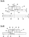
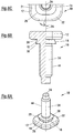
- the press-in element 10 could also be realized as a bolt element 10, as in the FIGS. 6A to 6C . 7A and 7B is shown.
- the press-in element 10 is provided with a shaft part 54 with external thread 44 which extends away from the side facing away from the head part 12 side 28 of the collar 14 in the direction of the central longitudinal axis 24. That is, with a shaft portion 54 with external thread 44 instead of a hollow passage with internal thread 44.
- the bolt element corresponds to the nut member according to the Fig. 1A to 1C
- Sheet preparation according to Fig. 7A and the Einpresssituation according to 7B also comply with the sheet metal preparation according to Fig. 2A and the installation situation according to Fig. 2B ,
- the design of the head portion 12 and the collar 14 of the bolt member 10 as well as the sheet preparation and installation situation could be as shown in the examples Figs. 3A to 3C and 4A and 4D, respectively.
- the design of the head portion 12 and the collar 14 of the bolt member as well as the sheet metal preparation and installation situation the examples according to Fig. 1A to 1C and 5A and 5D, respectively.
- an assembly part results from a press-in element 10 in combination with a panel 20, in particular in the form of a sheet metal part, wherein the collar is at least substantially polygonal in cross section 14 is laterally displaceable in the polygonal hole 18 of the panel 20, wherein panel material extends from the edge region of the hole 18 into the notches 38 formed between the polygonal collar 14 and the underside of the header but does not reach the bottom of the notches 38 ensuring the lateral displaceability of the press-in element 10 relative to the panel 20, but an axial separation of the press-in element 10 is prevented by the panel 20 due to the material overlap of the sheet material with the polygonal collar 14 within the notches 38.
- Figs. 8A and 8B There two different other examples of non-circular cross-sectional shapes of a collar 14 and the respectively associated head part 12 of a press-in element 10 are shown. It is understood that the cross-sectional shape of the hole of the corresponding component (not shown) is chosen to be complementary to the cross-sectional shape of the respective collar 14.
- Fig. 8A is the cross-sectional shape elliptical 56 with major axis 58 and minor axis 60.
- the cross-sectional shape is ice-cup-like 62 having a central, square or rectangular region 64 and semi-circular regions 66 on two opposite imaginary sides 68 of the central region 64.
- the head portion 12 of the press-fit element will have the same shape as the respective collar 14, with the expansion of the head portion 12 is greater than that of the collar to form the component abutment surface 21 on the underside 22 of the head portion.
- the nut member 10 here has a collar 14 with a polygonal punching at the bottom 22 of the head portion 12 of the nut member 10.
- the dimension between the punching portion of the nut member on the free end face 28 of the collar 14 and the bottom 21 of the head portion 12 is greater than the material thickness of the component 20 into which the nut element is introduced.
- the polygonal shape of the nut punches a required for the function large hole with transverse dimensions corresponding to those of the free end face 28 of the collar 14.
- a bead 70 is formed in the component, whereby the projection 72 of the punching area or the collar of the nut compensated and the possibility for a flush screwing of another component, not shown, on the underside 40 of the component 20 outside the bead 70 is given.
- the bead 70 is produced in that a hold-down 82 of the setting head 77 is provided with a recess 78 whose shape corresponds to the bead on the upper side of the sheet metal.
- the die 74 is provided with a cylindrical projection 75 which corresponds to the shape of the bead 70 on the underside of the sheet metal.
- the hold down 82 is biased downwardly by spring force and, during the closing of the press (not shown) in which the setting head 77 and die 74 are installed, first clamps the sheet metal member 20 against the die thereby forming the bead 70 first.
- the punch 80 With increasing closing of the press, the punch 80 is pressed down and presses the press-in which is located in the punch channel within the bodice and below the stamp, against the sheet metal part and punches a punched slug from the sheet metal part approximately in the middle of the bead 70th During the blanking movement gives way to the hold-down 82 against the spring bias, so to speak relative to the punch 80 back.
- Fig. 9 shows the situation after the nut is inserted and the assembly part is raised inside the press but before removal from the press.
- a setting or punching head 77 which is well known per se and of which only some components in the Fig. 9 is shown is used to introduce the press-in element 10 self-stamping in a component 20.
- the free end face 28 of the collar 14 is used by the exertion of pressure by a punch 80 of the setting head 77 on the head portion 12 of the press-in 10 and with simultaneous support of the component 20 on a perforated die 74 with a non-circular central opening 76 in order to punch a non-circular hole 18 having a shape corresponding to the free end face 28 of the press-in element 10 in the component 20.
- non-circular hole 76 of the die is provided with transverse dimensions ⁇ 2, which are chosen slightly larger than the corresponding transverse dimensions ⁇ 1 of the free end face 28 of the collar 14.
- transverse dimensions ⁇ 2 which are chosen slightly larger than the corresponding transverse dimensions ⁇ 1 of the free end face 28 of the collar 14.
- the downwardly diverging hole 18 using a punch (with the free end face 28 of the collar 14) in combination with a perforated die 74 with an opening 76 of larger transverse dimensions.
- a punch (the free end face 28 of the collar 14) cutting a smooth-walled hole (with walls parallel to the central longitudinal axis 24) in the initial region of the perforation 18 and then a punched billet (not shown) of divergent shape from the remaining thickness of the sheet metal part 20 breaks down, wherein the maximum diameter of the punching orifice is determined by the diameter of the hole ⁇ 2 of the perforated die 74.
- the degree of diverging of the blank is determined by the sheet thickness, the transverse dimensions of the free face 28 of the collar 14, and the transverse dimensions of the die opening 76. In this way, the displacement of the press-in element in the component 20 can be increased, which is of advantage.
Abstract
Ein Zusammenbauteil wird beschrieben, das aus einem Bauteil und einem am Bauteil angebrachten als Verschiebeelement ausgebildeten Element besteht, das ein Kopfteil, eine an einer Stirnseite des Kopfteils vorgesehene Bauteilanlagefläche und einen sich innerhalb der Bauteilanlagefläche angeordneten und von dieser wegragenden Kragen aufweist, der eine Querschnittsform hat , der nicht kreisrund ist. Der Kragen ist mit Spiel in ein komplementär zur Querschnittsform geformtes Loch des Bauteils eingesetzt und weist Außenflächen auf, die in Richtung der genannten Stirnseite des Kopfteils und in Bezug auf die mittlere Längsachse des Elements schräg zulaufen und mit dieser einen spitzen Winkel bilden. Der der Bauteilanlagefläche benachbarte Randbereich des Loches des Bauteils erstreckt sich in zwischen dem Kragen und der Stirnseite des Kopfteils ausgebildeten Kerben hinein, erreicht aber den Grund der Kerben nicht, wobei ein Freiraum entsteht, der eine seitliche Verschiebbarkeit des Elements relativ zum Bauteil gewährleistet. Eine axiale Trennung des Elements von dem Bauteil ist aufgrund von Materialüberlappung des Bauteilmaterials mit dem Kragen innerhalb der Kerben unterbunden. Es werden auch Elemente und Verfahren zur Herstellung des Zusammenbauteils beansprucht.An assembly part is described which consists of a component and an element attached to the component, designed as a sliding element, which has a head part, a component contact surface provided on an end face of the head part and a collar which is arranged within the component contact surface and protrudes from it and has a cross-sectional shape that is not circular. The collar is inserted with play in a complementary to the cross-sectional shape of the shaped hole of the component and has outer surfaces which taper towards the said end face of the head part and with respect to the central longitudinal axis of the element and form an acute angle with it. The edge area of the hole of the component adjacent to the component contact surface extends into notches formed between the collar and the end face of the head part, but does not reach the bottom of the notches, creating a free space that ensures that the element can be moved laterally relative to the component. An axial separation of the element from the component is prevented due to the material overlapping of the component material with the collar within the notches. Elements and methods of making the assembly are also claimed.
Description
Die vorliegende Erfindung betrifft ein Zusammenbauteil bestehend aus einem Bauteil und einem am Bauteil angebrachten als Verschiebeelement ausgebildeten Element, das ein Kopfteil, eine an einer Stirnseite des Kopfteils vorgesehene Bauteilanlagefläche und einen sich innerhalb der Bauteilanlagefläche angeordneten und einen von dieser wegragenden Kragen aufweist, der eine Querschnittsform hat, der nicht kreisrund ist. Ferner betrifft die Erfindung ein Element das zur Anwendung in ein derartiges Zusammenbauteil ausgelegt ist und Verfahren zur Herstellung eines solchen Zusammenbauteils.The present invention relates to an assembly component consisting of a component and a component mounted on the element designed as a sliding element, which has a head portion, provided on an end face of the head part component contact surface and disposed within the component contact surface and a projecting from this collar having a cross-sectional shape has, which is not circular. Furthermore, the invention relates to an element which is designed for use in such an assembly component and method for producing such a component assembly.
Ein Zusammenbauteil der eingangs genannten Art ist der
Hauptaufgabe der vorliegenden Erfindung ist es, ein Zusammenbauteil der eingangs genannten Art sowie ein geeignetes Element zur Anwendung im Zusammenbauteil und ein entsprechende Herstellungsverfahren vorzusehen, wobei das Element verschiebbar im Bauteil vorliegt und daher als Verschiebeelement betrachtet werden kann und zwar ohne das Element in einem Blechkäfig unterbringen zu müssen, wodurch der Blechkäfig und der entsprechende Anschweißvorgang, der ohnehin bei manchen Bauteilen wie solche aus Verbundblechen gar nicht möglich ist, entfallen können.The main object of the present invention is to provide an assembly part of the type mentioned above and a suitable element for use in the component assembly and a corresponding manufacturing method, wherein the element is slidably present in the component and therefore can be considered as a displacement element and without accommodating the element in a sheet metal cage to have, whereby the sheet metal cage and the corresponding welding, which is not possible anyway with some components such as composite sheets, can be omitted.
Diese Aufgabe wird erfindungsgemäß bei einem Zusammenbauteil der eingangs genannter Art dadurch gelöst, dass der Kragen, der mit Spiel in ein komplementär zur Querschnittsform geformtes Loch des Bauteils eingesetzt ist, dass der Kragen Außenflächen aufweist, die in Richtung der genannten Stirnseite des Kopfteils und in Bezug auf die mittlere Längsachse des Elements schräg zulaufen und mit dieser einen spitzen Winkel bilden, dass der der Bauteilanlagefläche benachbarte Randbereich des Loches des Bauteils sich in zwischen dem Kragen und der Stirnseite des Kopfteils ausgebildeten Kerben hineinerstreckt, aber auf den Grund der Kerben nicht reicht, wobei ein Freiraum entsteht, der eine seitliche Verschiebbarkeit des Elements relativ zum Bauteil gewährleistet, und dass eine axiale Trennung dass Elements von dem Bauteil aufgrund von Materialüberlappung des Bauteilmaterials mit dem Kragen innerhalb der Kerben unterbunden ist.This object is achieved in an assembly part of the aforementioned type in that the collar is inserted with play in a complementary shaped to the cross-sectional shape hole of the component, that the collar has outer surfaces, in the direction of said end face of the head part and in relation tapering towards the central longitudinal axis of the element and forming therewith an acute angle such that the edge area of the hole of the component adjacent the component abutment extends into notches formed between the collar and the face of the head but not sufficient to the bottom of the notches a free space is created which ensures lateral displaceability of the element relative to the component, and that axial separation of the element from the component due to material overlap of the component material with the collar within the notches is prevented.
In der vorliegenden Erfindung wird das Element vorzugsweise als Einpresselement realisiert, es könnte jedoch auch als Nietelement ausgelegt werden. In diesem Fall wird das freie Ende des Kragens so ausgebildet, dass es radial nach außen umgelegt werden kann, um ein Nietbördel auszubilden, zum Beispiel durch die Kräfte, die während der Anbringung auf das Bauteil ausgeübt werden. Falls das Element als Nietelement realisiert wird, dann muss die Auslegung so erfolgen wie im vorigen Absatz beschrieben ist. D.h. der Kragen wird auch hier mit Spiel in ein komplementär zur Querschnittsform geformtes Loch des Bauteils eingesetzt, der Kragen wird Außenflächen aufweisen, die in Richtung der genannten Stirnseite des Kopfteils und in Bezug auf die mittlere Längsachse des Elements schräg zulaufen und mit dieser einen spitzen Winkel bilden, der der Bauteilanlagefläche benachbarte Randbereich des Loches des Bauteils wird sich in zwischen dem Kragen und der Stirnseite des Kopfteils ausgebildeten Kerben hineinerstrecken, aber auf den Grund der Kerben nicht reichen, wobei ein Freiraum entsteht, der eine seitliche Verschiebbarkeit des Elements relativ zum Bauteil gewährleistet, und eine axiale Trennung des Elements von dem Bauteil aufgrund von Materialüberlappung des Bauteilmaterials mit dem Kragen bzw. dem radial nach außen verformten Kragen innerhalb der Kerben unterbunden ist.In the present invention, the element is preferably realized as a press-in element, but it could also be designed as a rivet element. In this case, the free end of the collar is formed so that it can be folded radially outwards to form a Nietbördel, for example by the forces exerted on the component during mounting. If the element is realized as a rivet element, then the design must be carried out as described in the previous paragraph. That is, the collar is also used here with play in a complementary shaped to the cross-sectional shape hole of the component, the collar will have outer surfaces which taper in the direction of said end face of the head part and with respect to the central longitudinal axis of the element and with this an acute angle form, the peripheral component of the component mounting surface adjacent the hole of the component will hineinerstrecken in between the collar and the end face of the head part formed notches, but not on the bottom of the notches, creating a free space, which ensures a lateral displacement of the element relative to the component , and an axial separation of the element from the component due to Material overlap of the component material with the collar or the radially outwardly deformed collar is prevented within the notches.
Es bestehen mehrere Möglichkeiten, den Kragen des Elements bzw. das Loch im Bauteil mit einem nicht kreisrunden Querschnitt zu versehen. Besonders günstig ist es, wenn der Kragen eine zumindest im Wesentlichen polygonale Querschnittsform aufweist, wobei die polygonale Querschnittsform des Kragens und dementsprechend das polygonale Loch des Bauteils aus der Gruppe dreieckig, quadratisch, fünfeckig und hexagonal ausgewählt ist. Bevorzugterweise ist die Querschnittsform des Kragens und des Loches quadratisch, insbesondere mit gerundeten Ecken ausgebildet. Die quadratische Form ermöglicht es, einen ausgezeichneten Verschiebeweg in zwei zueinander rechtwinkelige Richtungen bezogen auf die lokale Ebene des Bauteils im Bereich der Anbringung des Elements zu erreichen und die gerundeten Ecken sorgen dafür, dass die Gefahr von Ermüdungsrissen in den Eckbereichen des Loches im Bauteil deutlich herabgesetzt werden kann. Darüber hinaus können so gute Verdrehsicherungseigenschaften gesichert werden, damit das Element aus dem Bauteil nur unter Anwendung zerstörerischer Kräfte herausgedreht werden kann.There are several ways to provide the collar of the element or the hole in the component with a non-circular cross-section. It is particularly favorable if the collar has an at least substantially polygonal cross-sectional shape, wherein the polygonal cross-sectional shape of the collar and accordingly the polygonal hole of the component is selected from the group triangular, square, pentagonal and hexagonal. Preferably, the cross-sectional shape of the collar and the hole is square, in particular formed with rounded corners. The square shape makes it possible to achieve an excellent displacement in two mutually perpendicular directions with respect to the local plane of the component in the region of attachment of the element and the rounded corners ensure that the risk of fatigue cracks in the corners of the hole in the component significantly reduced can be. In addition, so good anti-rotation properties can be secured so that the element can be unscrewed from the component only with the use of destructive forces.
Solche Formgebungen, die alle im Prinzip aus der eingangs genannten
Eine weitere alternative Querschnittsform besteht darin, dass der Kragen eine ovale bzw. elliptische Gestalt. Auch käme eine Querschnittsform des Kragens bzw. des Loches ähnlich wie ein Eisbehälter mit einem quadratischen oder rechteckigen Mittelbereich mit halbkreisförmigen Ansätzen an zwei sich gegenüberliegenden Seiten des Mittelbereiches in Frage. Auch solche Querschnittsformen, d.h. elliptische Querschnittsform oder eisbecherförmige Querschnittsform ermöglichen gute Verschiebewege mit herabgesetzter Ermüdungsgefahr und ausgezeichneten Verdrehsicherungseigenschaften.Another alternative cross-sectional shape is that the collar has an oval or elliptical shape. Also, a cross-sectional shape of the collar or hole would be similar to an ice container having a square or rectangular center region with semi-circular lobes on two opposite sides of the central region. Even such cross-sectional shapes, ie elliptical cross-sectional shape or sigmoidal cross-sectional shape allow good displacement with reduced fatigue and excellent anti-rotation properties.
Dadurch, dass das polygonale Loch in dem Bauteil bzw. im Blechteil vorgefertigt wird, kann es so groß gemacht werden, dass der polygonale Kragen an seiner freien Stirnseite, die die größten Querabmessungen aufweist, mit Spiel in das polygonale Loch eingesetzt werden kann. Durch eine gezielte Stauchung des Bauteils bzw. des Blechteils kann Bauteilmaterial bzw. Blechmaterial in dem Randbereich der Öffnung des polygonalen Loches auf der der Bauteilanlagefläche des Kopfes zugewandten Seite in die sich zwischen den schräg zulaufenden Außenflächen des Kragens und den Bauteilanlagefläche des Kopfteils bzw. der Blechanlagefläche des Elements gebildeten Kerben hineingedrückt werden, derart, dass es das Material den Kragen in radialer Richtung überlappt, und somit ein Herausziehen des Elements aus der Tafel bzw. dem Blechteil verhindert, jedoch nicht so weit in radialer Richtung in die Kerben hineindrückt, dass das Element seitlich festgehalten wird, sondern so, dass ein seitlicher Abstand zu den Böden der Kerben noch existiert, wobei ein Freiraum entsteht und die seitliche Verschiebbarkeit des Elements noch gegeben ist und zwar vorzugsweise in allen seitlichen Richtungen. Die gleichen Vorteile sind mit einer elliptischen oder eisbecherähnlichen Querschnittsform des Kragens bzw. des Loches mittels einer gezielten Stauchung des Bauteils bzw. des Blechteils zu erreichen.The fact that the polygonal hole is prefabricated in the component or in the sheet metal part, it can be made so large that the polygonal collar can be used at its free end face, which has the largest transverse dimensions, with play in the polygonal hole. By a specific compression of the component or of the sheet metal part or sheet material in the edge region of the opening of the polygonal hole on the component contact surface of the head side facing in between the obliquely tapered outer surfaces of the collar and the component contact surface of the head part and the sheet metal contact surface of the element, so as to prevent the material from overlapping the collar in the radial direction, thus preventing the element from being pulled out of the panel, but not pushing it radially into the notches so far that the element is held laterally, but so that a lateral distance to the bottoms of the notches still exists, with a free space is created and the lateral displacement of the element is still given, and preferably in all lateral directions. The same advantages can be achieved with an elliptical or ice cup-like cross-sectional shape of the collar or the hole by means of a targeted compression of the component or the sheet metal part.
Es werden vorzugsweise bei dem Element keine Verdrehsicherungsmerkmale in Form von vorstehenden Nasen oder Rippen oder entsprechenden Vertiefungen vorgesehen, die die Verschiebbarkeit des Elements verhindern könnten, da es erfindungsgemäß anerkannt worden ist, dass die erforderliche Verdrehsicherung im ausreichenden Maße und ausschließlich durch die polygonale Form des Loches und die des Kragens gewährleistet werden kann, und zwar auch dann, wenn eine gewisse gegenseitige Verdrehbarkeit des Elements und des Bauteils bzw. des Blechteils aufgrund der radialen Verschiebbarkeit unvermeidlich ist. Das Gleiche gilt für eine elliptische oder eisbecherähnliche Querschnittsform des Kragens bzw. des Loches.There are preferably provided in the element no anti-rotation features in the form of protruding lugs or ribs or corresponding recesses, which could prevent the displacement of the element, since it has been recognized according to the invention that the required anti-rotation sufficiently and exclusively by the polygonal shape of the hole and which of the collar can be ensured, even if some mutual rotatability of the element and the component or the sheet metal part due to the radial displacement is inevitable. The same applies to an elliptical or ice cup-like cross-sectional shape of the collar or the hole.
Der spitze Winkel zwischen den Außenflächen des Kragens und der mittleren Längsachse des Elements liegt vorzugsweise im Bereich von etwa 20° bis etwa 40°. Ein zu kleiner Winkel schränkt die radiale Verschiebbarkeit des Elements ein und setzt die Auspresssicherheit ab, während ein zu großer Winkel die erwünschte direkte Klemmung des weiteren Blechteils schwieriger zu erreichen macht, ohne dass das Kopfteil des Elements und das Kopfteil des Schraubelements unerwünscht vergrößert werden müssen. Wenn hierin gesagt wird, dass eine Form zumindest im Wesentlichen polygonal ist, bedeutet dies, dass die Ecken zwischen benachbarten Seitenflächen gerundet sein können, was dem Ermüdungsverhalten des Zusammenbauteils zu Gute kommt.The acute angle between the outer surfaces of the collar and the central longitudinal axis of the element is preferably in the range of about 20 ° to about 40 °. Too small an angle limits the radial displaceability of the element and relieves the Auspresssicherheit, while a too large angle makes the desired direct clamping of the other sheet metal part difficult to achieve without the head of the element and the head of the screw must be increased undesirably. When it is said herein that a shape is at least substantially polygonal, this means that the corners between adjacent side surfaces can be rounded, which the fatigue behavior of the component comes to good.
Auch der Kopfteil des Elements wird vorzugsweise im Querschnitt polygonal gestaltet und zwar mit der gleichen Anzahl von Seitenflächen wie der im Querschnitt polygonale Kragen. Dies vereinfacht die Herstellung des Elements durch zum Beispiel ein Kaltschlagverfahren und sorgt dafür, dass die Blauteilanflagefläche eine gleichmäßige Ausbildung aufweist. Alternativ hierzu könnte man aber zum Beispiel eine Kopfform verwenden, die bei einem Kragen mit einer elliptischen oder eisbecherähnlichen Querschnittsform eine entsprechende Querschnittsform aufweist, oder es könnte bei allen Varianten des Kragens eine Kopfform gewählt werden, die im Querschnitt kreisrund ist. Auf jeden Fall kann der Kopfteil in Seitenansicht ballig gerundet sein, eine Formgebung, die leicht durch ein Kaltschlagverfahren realisiert werden kann. Ferner können Elemente mit einer derartigen Formgebung auch in bekannten Setzköpfen der Anmelderin, die bei deren Kunden stehen, kostensparend verarbeitet werden.Also, the head portion of the element is preferably polygonal in cross-section and that with the same number of side surfaces as the cross-sectionally polygonal collar. This simplifies the manufacture of the element by, for example, a cold striking process and ensures that the Blauteilanflagefläche has a uniform design. Alternatively, but could for example use a head shape having a corresponding cross-sectional shape in a collar with an elliptical or Eisbecherähnlichen cross-sectional shape, or it could be chosen in all variants of the collar, a head shape which is circular in cross-section. In any case, the headboard can be spherically rounded in side view, a shape that can be easily realized by a cold impact method. Furthermore, elements with such a shape can also be processed cost-saving in known setting heads of the applicant, which are their customers.
Eine Möglichkeit, das Bauteilmaterial im Randbereich des polygonalen Loches radial zu verschieben, besteht darin, die dem polygonalen Kragen zugewandte Seite des Kopfteils mindestens an den Stellen der Seitenflächen des polygonalen Kragens mit vorstehenden Verdrängungsflächen zu versehen, die bei Abstützung des Bauteils auf einer ebenen Fläche oder auf einer Matrize mit einer flachen Stirnseite und bei der Ausübung von Druck auf das Kopfteil des Elements dazu dienen, die erwünschte Verdrängung des Bauteilmaterials zu bewirken, wobei das Ausmaß der radialen Verdrängung des Bauteilmaterials durch das Volumen der vorstehenden Verdrängungsflächen bestimmt wird. Das Volumen der vorstehenden Verdrängungsflächen wird durch die radiale und umfangsmäßige Erstreckung sowie die axiale Höhe derselben bestimmt. Dabei soll die axiale Höhe möglichst klein gehalten werden, da dies zu einer axialen Vertiefung in der der Bauteilanlagefläche des Kopfteils gegenüberliegenden Seite des Bauteils führt, die die radiale Verschiebbarkeit des Elements verhindern bzw. ungünstig beeinflussen kann. Entsprechende Verdrängungsflächen können auf der Bauteilanlagefläche eines Elements mit einer anderen Querschnittsform, Z.B. mit einer elliptischen oder eisbecherähnlicher Querschnittsform vorgesehen werden.One way to move the component material radially in the edge region of the polygonal hole, is to provide the polygonal collar side facing the head portion at least at the sites of the side surfaces of the polygonal collar with protruding displacement surfaces, which in support of the component on a flat surface or on a die with a flat face and upon the application of pressure to the head portion of the element serve to effect the desired displacement of the component material, the extent of radial displacement of the component material being determined by the volume of the protruding displacement surfaces. The volume of the protruding displacement surfaces is determined by the radial and circumferential extent and the axial height thereof. In this case, the axial height should be kept as small as possible, as this leads to an axial recess in the component abutment surface of the head part opposite side of the component, which can prevent or adversely affect the radial displacement of the element. Corresponding displacement surfaces may be provided on the component abutment surface of an element having a different cross-sectional shape, for example, having an elliptical or ice cup-like cross-sectional shape.
Das erfindungsgemäße Element kann entweder als Mutterelement ausgebildet sein und eine mittlere Längspassage aufweisen oder als Bolzenelement mit einem vom Kragen aus in Richtung vom Kopfteil weg erstreckenden Schaftteil.The element according to the invention can either be designed as a nut element and have a central longitudinal passage or as a bolt element with a collar part extending away from the head part in the direction of the shaft part.
Die mittlere Längspassage des Mutterelements kann mit einem Gewindezylinder versehen werden oder eine glatte zylindrische Bohrung aufweisen, die mittels einer gewindeschneidenden oder-formenden Schraube zu einem Gewindezylinder umgeformt werden kann.The central longitudinal passage of the nut member may be provided with a threaded cylinder or have a smooth cylindrical bore, which can be converted by means of a thread-cutting or -forming screw to a threaded cylinder.
Alternativ hierzu kann das Zusammenbauteil so ausgebildet werden, dass die genannte Seite des Kopfteils, d.h. die Bauteilanlagefläche in einer Ebene senkrecht zur mittleren Längsachse des Elements liegt, und die Verdrängung des Bauteilmaterials anderweitig erfolgt.Alternatively, the assembly member may be formed so that said side of the header, i. the component abutment surface lies in a plane perpendicular to the central longitudinal axis of the element, and the displacement of the component material otherwise takes place.
Dies kann zum Beispiel erfindungsgemäß dadurch geschehen, dass eine Ringvertiefung in der der Bauteilanlagefläche des Kopfteils abgewandten Seite des Bauteils um das polygonale Loch herum, vorgesehen ist, oder dadurch, dass diskrete Vertiefungen, die in einem Ring in der der Bauteilanlagefläche des Kopfteils abgewandten Seite des Bauteils um das polygonale Loch herum angeordnet sind, vorgesehen sind, die für die Verdrängung des Bauteilmaterials in die Kerben verantwortlich ist bzw. sind.This can be done according to the invention, for example, by providing an annular recess in the side of the component facing away from the component abutment surface of the head part around the polygonal hole, or by discrete recesses in a ring in the side facing away from the component abutment surface of the head part Component are arranged around the polygonal hole, are provided, which is responsible for the displacement of the component material in the notches or are.
Ein erfindungsgemäßes Verfahren zur Herstellung eines oben beschriebenen erfindungsgemäßen Zusammenbauteils kann so ausgelegt werden, dass ein nicht kreisrundes Loch in dem Bauteil vorgefertigt wird mit Querabmessungen größer als die entsprechenden maximalen Querabmessungen des Kragens im Bereich seiner freien Stirnseite, damit dieser in das nicht kreisrunde Loch hineingeführt werden kann, dass das Tafelmaterial aus dem Randbereich des nicht kreisrunden Loches in die sich zwischen den Seitenflächen des Kragens und der Bauteilanlagefläche des Kopfteils ausgebildeten Kerben verdrängt wird; wobei das Tafelmaterial nicht soweit verdrängt wird, dass es auf den Grund der Kerben reicht, wobei die seitliche Verschiebbarkeit des Elements relativ zum Bauteil gewährleistet ist, aber nur so weit, dass eine axiale Trennung dass Elements von dem Bauteil aufgrund der Materialüberlappung des Tafelmaterials mit dem nicht kreisrunden Kragen innerhalb der Kerben unterbunden ist.A method according to the invention for producing a component part described above according to the invention can be designed so that a non-circular hole is prefabricated in the component with transverse dimensions greater than the corresponding maximum transverse dimensions of the collar in the region of its free end, so that they are guided into the non-circular hole that the sheet material is displaced from the edge portion of the non-circular hole into the notches formed between the side surfaces of the collar and the component abutting surface of the head portion; wherein the sheet material is not displaced so far that it reaches the bottom of the notches, wherein the lateral displacement of the element is ensured relative to the component, but only so far that an axial separation of the elements of the component due to the material overlap of the sheet material with the non-circular collar is prevented within the notches.
In einer konkreten erfindungsgemäß bevorzugten Ausführung des oben beschriebenen Verfahrens wird das vorgefertigte nicht kreisrunde Loch des Bauteils mit einem erhabenen Randbereich auf der der Bauteilanlagefläche des Kopfteils zugewandte Seite versehen, wobei beim Einführen des Kragens in das Bauteil der erhobene Randbereich durch die Bauteilanlagefläche des Kopfteils bei gleichzeitiger Abstützung der dem Kopfteil abgewandten Seite des Bauteils flachgepresst wird, um hierdurch das Verdrängen des Bauteilmaterials im Randbereich zu bewirken.In a specific preferred embodiment of the method described above, the prefabricated non-circular hole of the component is provided with a raised edge region on the component contact surface of the head part facing side, wherein during insertion of the collar into the component of the raised edge area by the component contact surface of the head part at the same time Supporting the side facing away from the head part of the component is pressed flat, thereby causing the displacement of the component material in the edge region.
In einer alternativen Auslegung des erfindungsgemäßen Verfahrens wird der Randbereich des vorgefertigten Lochs des Bauteils, der im Bereich der Anbringung des Elements in einer Ebene liegt, mittels Verdrängungsflächen, die an der Bauteilanlagefläche des Kopfteils mindestens im Bereich der Seitenflächen des Kragens vorgesehen sind, beim Einführen des Kragens in das Bauteil und durch die Bauteilanlagefläche des Kopfteils bei gleichzeitiger Abstützung der Unterseite des Bauteils eingedrückt, um hierdurch das Verdrängen des Bauteilmaterials im Randbereich in die Kerben hinein, zu bewirken.In an alternative embodiment of the method according to the invention, the edge region of the prefabricated hole of the component, which lies in the region of attachment of the element in a plane, by means of displacement surfaces which are provided on the component contact surface of the head part at least in the region of the side surfaces of the collar during insertion of the Collar pressed into the component and by the component abutment surface of the head part with simultaneous support of the underside of the component, thereby causing the displacement of the component material in the edge region in the notches into.
In einer weiteren alternativen Auslegung des erfindungsgemäßen Verfahrens, wird mittels einer Matrize, die mit einer Ringerhebung oder mit diskreten, in einem Ring angeordneten Vorsprüngen versehen ist, die der Bauteilanlagefläche des Kopfteils abgewandten Seite der Tafel um das polygonale Loch herum mit einer Ringvertiefung bzw. mit diskreten Vertiefungen, die in einem Ring angeordnet sind, versehen, die für die Verdrängung des Bauteilmaterials in die Kerben verantwortlich ist bzw. sind.In a further alternative embodiment of the method according to the invention, by means of a die, which is provided with a Ringerhebung or discrete, arranged in a ring projections, the component abutment surface of the head portion facing away from the panel with a ring recess around or around the polygonal hole discrete recesses arranged in a ring which is responsible for the displacement of the component material into the notches.
Besonders günstig ist es, wenn ein Verfahren zur Herstellung eines erfindungsgemäßen Zusammenbauteils nach mindestens einem der entsprechenden Patentansprüche 1 bis 10 verwendet wird, bei dem durch die Ausübung von Druck auf den Kopfteil des Elements und bei gleichzeitiger Abstützung des Bauteils auf einer Lochmatrize mit einer mittleren Öffnung, die freie Stirnseite des Kragens benutzt wird, um ein nicht kreisrundes Loch in das Bauteil zu stanzen. D.h. das Element wird selbststanzend in das Bauteil eingesetzt, wodurch das erfindungsgemäße Verfahren einstufig und daher besonders wirtschaftlich zeitsparend durchgeführt werden kann. Ferner können auf diese Weise Probleme mit der Ausrichtung des Elements bzw. dessen Kragen und dem Bauteil vermieden werden, da der Kragen sein eigenes formangepasstes Loch in das Bauteil schneidet und die konkrete Orientierung des Kragens um die mittlere Längsachse des Bauteils herum völlig unwichtig ist. Dabei kann die Stauchung des Bauteilmaterials nach einer der oben beschriebenen Arten erfolgen.It is particularly advantageous if a method for producing a component according to the invention according to at least one of the corresponding claims 1 to 10 is used, in which by the exertion of pressure on the head portion of the element and simultaneous support of the component on a perforated die with a central opening , the free end of the collar is used to punch a non-circular hole in the component. This means that the element is used self-piercing in the component, whereby the inventive method can be carried out in one stage and therefore particularly economical time-saving. Furthermore, problems with the orientation of the element or its collar and the component can be avoided in this way, since the collar cuts its own shape-matched hole in the component and the concrete orientation of the Collar around the central longitudinal axis of the component around completely unimportant. In this case, the compression of the component material can take place according to one of the types described above.
Besonders günstig bei dem zuletzt genannten Verfahren ist es, wenn das nicht kreisrunde Loch der Matrize mit Querabmessungen etwas größer als die entsprechenden Querabmessungen der freien Stirnseite des Kragens versehen wird, damit die entstehenden Seitenwänden des so gestanzten Loches des Bauteils in Richtung der mittleren Längsachse des Elements und in Richtung vom Kopfteil weg zumindest im dem Kopfteil abgewandten Bereich divergierend ausgebildet sind. Hierdurch kann eine deutliche Erhöhung des Verschiebewegs erreicht werden.Particularly favorable in the latter method is when the non-circular hole of the die is provided with transverse dimensions slightly larger than the corresponding transverse dimensions of the free end face of the collar, so that the resulting side walls of the thus punched hole of the component in the direction of the central longitudinal axis of the element and are divergent in the direction away from the head part, at least in the area facing away from the head part. As a result, a significant increase in the displacement can be achieved.
Die Erfindung wird nachfolgend anhand von Ausführungsbeispielen, die in den Figuren gezeigt sind, näher erläutert. In den Figuren zeigen:
- Fig. 1A bis 1C
- ein erfindungsgemäßes Einpresselement in der Form eines Mutterelements und zwar in einer perspektivischen Ansicht (
Fig. 1A ), in einer Ansicht, die in einer Ebene auf der linken Seite der mittleren Längsachse geschnitten und in Seitenansicht auf der rechten Seite der mittleren Längsachse gezeigt ist (Fig. 1B ) sowie zur Hälfte in einer Draufsicht von unten (Fig. 1C ), - Fig. 2A und 2B
- zwei Zeichnungen, die das Einbringen des Einpresselements gemäß den
Fig. 1A bis 1C in ein Blechteil zeigen, - Fig. 3A bis 3C
- Ansichten entsprechend den Ansichten gemäß den
Figuren 1A bis 1C , jedoch von einem modifizierten erfindungsgemäßen Einpresselement auch in Form eines Mutterelements, aber mit Verdrängungsflächen auf dem Kopfteil. - Fig. 4A und 4B
- zwei Zeichnungen, die das Einbringen des Einpresselements gemäß den
Fig. 3A bis 3C in ein Blechteil zeigen, - Fig. 5A und 5B
- zwei Zeichnungen, die ein alternatives Verfahren zur Einbringung des Einpresselements gemäß den
Fig. 1A bis 1C in ein Blechteil zeigen, - Fig. 6A bis 6C
- Ansichten entsprechend den Ansichten gemäß den
Figuren 1A bis 1C , jedoch von einem modifizierten erfindungsgemäßen Einpresselement in Form eines Bolzenelements, - Fig. 7A und 7B
- zwei Zeichnungen, die das Einbringen des Einpresselements gemäß den
Fig. 6A bis 6C in ein Blechteil zeigen, - Fig. 8A und 8B
- Zeichnungen, um mögliche weitere Querschnittsformen eines Einpresselements und dementsprechend die Querschnittsform eines nicht kreisrunden Loches eines Bauteils zu verdeutlichen und
- Fig. 9
- eine schematische Zeichnung, um die selbststanzende Einbringung eines erfindungsgemäßen Einpresselements zu verdeutlichen.
- Fig. 1A to 1C
- an inventive press-in element in the form of a nut member and in a perspective view (
Fig. 1A ), in a view cut in a plane on the left side of the central longitudinal axis and shown in side view on the right side of the central longitudinal axis (Fig. 1B ) and half in a plan view from below (Fig. 1C ) - FIGS. 2A and 2B
- two drawings showing the insertion of the press-in according to the
Fig. 1A to 1C show in a sheet metal part, - Figs. 3A to 3C
- Views according to the views according to the
FIGS. 1A to 1C , but of a modified Einpresselement invention also in the form of a nut member, but with displacement surfaces on the head part. - FIGS. 4A and 4B
- two drawings showing the insertion of the press-in according to the
Figs. 3A to 3C show in a sheet metal part, - Figs. 5A and 5B
- two drawings showing an alternative method for introducing the press-in according to
Fig. 1A to 1C show in a sheet metal part, - FIGS. 6A to 6C
- Views according to the views according to the
FIGS. 1A to 1C but of a modified press-in element according to the invention in the form of a bolt element, - Figs. 7A and 7B
- two drawings showing the insertion of the press-in according to the
FIGS. 6A to 6C show in a sheet metal part, - Figs. 8A and 8B
- Drawings to illustrate possible further cross-sectional shapes of a press-in element and, accordingly, the cross-sectional shape of a non-circular hole of a component and
- Fig. 9
- a schematic drawing to illustrate the self-piercing introduction of a press-in element according to the invention.
Bezug nehmend auf die
Der spitze Winkel α liegt vorzugsweise im Bereich von etwa 20° bis etwa 40°.The acute angle α is preferably in the range of about 20 ° to about 40 °.
In allen gezeigten Beispielen ist der Querschnitt des Kragens 14 und das polygonale Loch 18 quadratisch mit gerundeten Ecken 26 gezeigt. Der Querschnitt des Kragens 14 und die Formgebung des Loches 18 sind gleich, müssen aber nicht unbedingt quadratisch sein. Der zumindest im Wesentlichen polygonale Querschnitt des Kragens 14 und dementsprechend das polygonale Loch 18 in der Tafel 20 können zum Beispiel aus der Gruppe dreieckig, quadratisch, fünfeckig und hexagonal oder oval ausgewählt werden, wie beispielsweise aus der
In allen hier gezeigten Beispielen ist auch das Kopfteil 12 im Querschnitt polygonal und zwar mit der gleichen polygonalen Form wie der Kragen 14.In all examples shown here, the
Die
Bei der Anwendung eines Folgeverbundwerkzeugs wird das polygonale Loch 18 in einer Station eines Folgeverbundwerkzeugs (nicht gezeigt) durchgeführt, während das Einführen des Einpresselements in einer weiteren Station des Folgeverbundwerkzeugs durchgeführt wird. Für jeden Hub der Presse wird ein polygonales Loch in einer Station des Folgeverbundwerkzeugs ausgestanzt, und in einer weiteren Station ein Einpresselement in das polygonale Loch eingesetzt, das in einem früheren Arbeitshub der Presse hergestellt wurde. Wie an sich gut bekannt ist, werden nach jedem Hub der Presse die Werkstücke, d.h. entweder einzelne Bauteile 20 oder ein Streifen aus mehreren zunächst zusammenhängenden Werkstücken bzw. Bauteilen 20 (Tafel), um eine vorgegebene Distanz innerhalb des Folgeverbundwerkzeugs weitertransportiert.When using a progressive compound tool, the
Wie aus der
Man sieht auch aus der
Schließlich sieht man aus den
Besonders günstig bei dieser Ausführung ist, dass im eingebauten Zustand der
Obwohl bei einem Verschiebeelement an sich gewünscht ist, dass das Einpresselement 10 unverlierbar am Blechteil 20 befestigt ist, bevor ein weiteres Bauteil angeschraubt wird, weshalb in der Ausführung gemäß
Aus dem oben Gesagten geht hervor, dass das vorgefertigte polygonale Loch 18 der Tafel 20 mit einem erhobenen Randbereich (Lippe) 32 auf der der Bauteilanlagefläche 21 des Kopfteils 12 zugewandten Seite 46 versehen ist, und beim Einführen des Kragens 14 in die Tafel 20 der erhobene Randbereich 32 (d.h. die Lippe 32) durch die genannte Seite 22 des Kopfteils bei gleichzeitiger Abstützung der Unterseite 40 der Tafel 20 flachgepresst bzw. gestaucht wird, um hierdurch das Verdrängen des Tafelmaterials im Randbereich zu bewirken.From the above, it can be seen that the prefabricated
Eine alternative Auslegung des Einpresselements 10 und des Verfahrens zum Anbringen des Einpresselements in das Blechteil 20 wird nun anhand der
Bei der Ausführung gemäß den
In der Ausführung gemäß den
In allen bisherigen Ausführungsformen ist das Einpresselement als Mutterelement mit einem mittig angeordneten Gewindezylinder bzw. Innengewinde 44 realisiert worden.In all previous embodiments, the press-in element has been realized as a nut element with a centrally arranged threaded cylinder or
Das Einpresselement 10 könnte aber auch als Bolzenelement 10 realisiert werden, wie in den
Es wäre durchaus möglich, die Auslegung des Bolzenelements 10 und die Blechvorbereitung anders auszulegen. Zum Beispiel könnte die Auslegung des Kopfteils 12 und des Kragens 14 des Bolzenelements 10 sowie die Blechvorbereitung und die Einbausituation den Beispielen gemäß
Egal, ob man mit einem Einpresselement 10 in Form eines Mutterelements oder in Form eines Bolzenelements arbeitet, ergibt sich ein Zusammenbauteil bestehend aus einem Einpresselement 10 in Kombination mit einer Tafel 20, insbesondere in Form eines Blechteils, wobei der im Querschnitt zumindest im Wesentlichen polygonale Kragen 14 sich seitlich verschiebbar in dem polygonalen Loch 18 der Tafel 20 befindet, wobei Tafelmaterial aus dem Randbereich des Loches 18 in den zwischen dem polygonalen Kragen 14 und der Unterseite des Kopfteils gebildeten Kerben 38 hineinerstreckt, aber auf den Grund der Kerben 38 nicht reicht, wobei die seitliche Verschiebbarkeit des Einpresselements 10 relativ zur Tafel 20 gewährleistet, aber eine axiale Trennung des Einpresselements 10 von der Tafel 20 aufgrund der Materialüberlappung des Tafelmaterials mit dem polygonalen Kragen 14 innerhalb der Kerben 38 unterbunden ist.Regardless of whether one works with a press-in
Bei dem Zusammenbauteil wird, wenn Verdrängungsflächen auf der Seite des Kopfteils vorgesehen und in das Tafelmaterial hinein gedrückt sind, Tafelmaterial aus dem Randbereich des polygonalen Loches 18 in die Kerben 38 verdrängt.In the assembling part, when displacement surfaces are provided on the side of the head part and pressed into the sheet material, sheet material is displaced from the edge area of the
Bezug nehmend auf die
In der
Es wird nun ein selbststanzendes Verfahren zur Herstellung eines erfindungsgemäßen Zusammenbauteils erläutert und zwar anhand eines Einpresselements in der Form eines Mutterelements gemäß den
Um hier Abhilfe zu schaffen, wird in diesem Beispiel eine Sicke 70 im Bauteil ausgebildet, wodurch den Überstand 72 des Stanzbereiches bzw. des Kragens der Mutter kompensiert und die Möglichkeit für eine bündige Verschraubung eines weiteren nicht gezeigten Bauteils an der Unterseite 40 des Bauteils 20 außerhalb der Sicke 70 gegeben ist.To remedy this situation, in this example, a
Die Sicke 70 wird dadurch erzeugt, dass ein Niederhalter 82 des Setzkopfes 77 mit einer Ausnehmung 78 versehen wird deren Formgebung der der Sicke auf der Blechoberseite entspricht. Die Matrize 74 wird mit einem zylindrischen Vorsprung 75 versehen welche die Formgebung der Sicke 70 auf der Blechunterseite entspricht. Der Niederhalter 82 wird nach Federkraft nach unten vorgespannt und klemmt während des Schließens der Presse (nicht gezeigt) in der der Setzkopf 77 und die Matrize 74 eingebaut sind, als erstes das Blechteil 20 gegen der Matrize wodurch die Sicke 70 als erstes geformt wird. Bei zunehmendes Schließen der Presse wird der Stempel 80 nach unten gedrückt und presst das Einpresselement das sich im Stempelkanal innerhalb des Miederhalters und unterhalb des Stempels befindet, gegen das Blechteil und stanzt so ein Stanzbutzen aus dem Blechteil in etwa in der Mitte der Sicke 70. Während der Einstanzbewegung weicht der Niederhalter 82 gegen die Federvorspannung sozusagen relativ zum Stempel 80 zurück.The
Das hier beschriebene Verfahren zur Herstellung eines Zusammenbauteils kann zusammengefasst, so betrachtet werden, dass ein Setz- bzw. Stanzkopf 77, der an sich gut bekannt ist und von dem nur einige Bauteile in der
Besonders günstig ist es, wenn das nicht kreisrunde Loch 76 der Matrize mit Querabmessungen Φ2 versehen wird, die etwas größer gewählt werden, als die entsprechenden Querabmessungen Φ1 der freien Stirnseite 28 des Kragens 14. Hierdurch werden die entsprechenden Seitenwände des so gestanzten Loches 18 des Bauteils 20 in Richtung der mittleren Längsachse 24 des Einpresselements 10 und in Richtung vom Kopfteil 12 weg zumindest im dem Kopfteil 12 abgewandten Bereich divergierend ausgebildet.It is particularly advantageous if the
Mit anderen Worten erfolgt die sich nach unten divergierende Lochung 18 unter Anwendung eines Lochstempels (mit der freien Stirnseite 28 des Kragens 14) in Kombination mit einer Lochmatrize 74 mit einer Öffnung 76 größeren Querabmessungen. Eine solche Auslegung führt dazu, dass der Lochstempel (die freie Stirnseite 28 des Kragens 14) im Anfangsbereich der Lochung 18 ein glattwandiges Loch (mit Wänden parallel zur mittleren Längsachse 24) schneidet und anschließend ein Stanzbutzen (nicht gezeigt) divergierender Gestalt aus der restlichen Dicke des Blechteils 20 herausbricht, wobei der maximale Durchmesser des Stanzbutzens durch den Durchmesser des Loches Φ2 der Lochmatrize 74 bestimmt wird. Der Grad des Divergierens des Stanzbutzens wird durch die Blechdicke, den Querabmessungen der freien Stirnseite 28 des Kragens 14 und den Querabmessungen der Öffnung76 der Matrize bestimmt. Hierdurch kann der Verschiebeweg des Einpresselements im Bauteil 20 vergrößert werden, welche vom Vorteil ist.In other words, the downwardly diverging
- 1010
- Einpresselementmaleconnector
- 1212
- Kopfteilheadboard
- 1414
- Kragencollar
- 1616
-
Außenflächen des Kragens 14Outer surfaces of the
collar 14 - 1818
- polygonales Lochpolygonal hole
- 2020
- Tafel, Bauteil bzw. BlechteilBoard, component or sheet metal part
- 2121
- Bauteil- bzw. BlechteilanlageflächeComponent or sheet metal part contact surface
- 2222
-
Unterseite des Kopfteils 12,Bottom of the
head part 12, - 2424
- mittlere Längsachse des Einpresselementscentral longitudinal axis of the press-in element
- 2626
-
gerundete Ecken des Kragens 14rounded corners of the
collar 14 - 2828
-
freie Stirnseite des Kragens 14free front of the
collar 14 - 3030
-
Seitenflächen des Loches 18Side surfaces of the
hole 18 - 3232
-
Lippe am Rande des Loches 18, bzw. erhobener RandbereichLip on the edge of the
hole 18, or raised edge area - 32'32 '
-
Lippe resultierend vom Flachpressen der Lippe 32Lip resulting from flat pressing of the
lip 32 - 3434
-
innere Flanke der Lippe 32inner flank of the
lip 32 - 3636
-
obere Stirnseite des Kopfteils 12upper end side of the
head part 12 - 3838
- Kerbennotch
- 3939
- Grund der KerbenReason of the notches
- 4040
- Unterseite des Bauteils bzw. des Blechteils 20Bottom of the component or the sheet metal part 20th
- 4141
- Freiraumfree space
- 4242
-
Verdrängungsflächen am Kopfteil 12Displacement surfaces on the
head part 12 - 4444
- Innengewinde, Außengewinde, GewindezylinderInternal thread, external thread, threaded cylinder
- 4646
-
Oberseite des Blechteils 20Top of the
sheet metal part 20 - 4848
- Matrizedie
- 5050
-
ringförmige Erhebung der Matrize 48annular elevation of the
die 48 - 5252
- Ringvertiefungring recess
- 5454
- Schaftteilshank part
- 5656
- elliptische Querschnittsformelliptical cross-sectional shape
- 5858
- Hauptachse der EllipseMain axis of the ellipse
- 6060
- Nebenachse der EllipseMinor axis of the ellipse
- 6262
- Eisbecher ähnliche QuerschnittsformIce cream cup-like cross-sectional shape
- 6464
- mittlerer Bereich der eisbecherähnlichen Querschnittsformmiddle region of the ice cup-like cross-sectional shape
- 6666
- halbkreisförmige Bereiche des mittleren Bereiches 64semi-circular regions of the central region 64
- 6868
- imaginäre Seiten des mittleren Bereiches 64imaginary sides of the central area 64
- 7070
- SickeBeading
- 7272
- ÜberstandGot over
- 7474
- Lochmatrizepiercing die
- 7575
-
zylindrischer Vorsprung der Lochmatrize 74cylindrical projection of the
perforated die 74 - 7676
-
das Loch bzw. die Öffnung der Lochmatrize 74the hole or the opening of the
perforated die 74 - 7777
- Setzkopfsetting head
- 7878
- zylindrische Vertiefung der Stirnseite des Setzkopfescylindrical recess of the front side of the setting head
- 8080
- Stempel des SetzkopfesStamp of the setting head
- 8282
-
Niederhalter des Setzkopfes 77Downholder of the setting
head 77 - ββ
- Winkelangle
- HH
-
axiale Höhe des Kragens 14axial height of the
collar 14 - DD
-
Dicke der Tafel 20Thickness of the
board 20 - αα
- WinkelαWinkelα
- Φ1Φ1
-
Querabmessung des nicht kreisrunden Kragens 14 am freien Stirnende 28Transverse dimension of the
non-circular collar 14 at the free end 28th - Φ1Φ1
-
Querabmessung des nicht kreisrunden Loches 76 der LochmatrizeTransverse dimension of the
non-circular hole 76 of the perforated die
Claims (17)
dadurch gekennzeichnet, dass der Kragen (14), der mit Spiel in ein komplementär zur Querschnittsform geformtes Loch (18) des Bauteils (20) eingesetzt ist, dass der Kragen (14) Außenflächen aufweist, die in Richtung der genannten Stirnseite (22) des Kopfteils und in Bezug auf die mittlere Längsachse des Elements schräg zulaufen und mit dieser einen spitzen Winkel (α) bilden, dass der der Bauteilanlagefläche benachbarte Randbereich des Loches des Bauteils in zwischen dem Kragen (14) und der Stirnseite (22) des Kopfteils (12) ausgebildeten Kerben (38) hineinerstreckt, aber auf den Grund (39) der Kerben (38) nicht reicht, wobei ein Freiraum (41) entsteht, der eine seitliche Verschiebbarkeit des Elements relativ zum Bauteil (20) gewährleistet, und dass eine axiale Trennung dass Elements (10) von dem Bauteil (20) aufgrund von Materialüberlappung des Bauteilmaterials mit dem Kragen (14) innerhalb der Kerben (38) unterbunden ist.Assembly component consisting of a component (20), in particular a sheet metal part, and a component (10) which is designed as a displacement element and has a head part (12), a component contact surface (21) provided on an end face (22) of the head part (12). and a collar (14) disposed within and projecting from the component abutment surface and having a cross-sectional shape that is non-circular,
characterized in that the collar (14) inserted with play into a complementary hole (18) of the component (20) is such that the collar (14) has outer surfaces facing towards said end face (22) of the Head portion and with respect to the central longitudinal axis of the element oblique and form with this an acute angle (α) that the component abutment surface adjacent edge region of the hole of the component in between the collar (14) and the end face (22) of the head part (12 ) formed notches, but on the bottom (39) of the notches (38) is not sufficient, with a free space (41) is formed, which ensures a lateral displaceability of the element relative to the component (20), and that an axial separation that element (10) is prevented from the component (20) due to material overlap of the component material with the collar (14) within the notches (38).
dadurch gekennzeichnet, dass der Kragen (14) eine zumindest im Wesentlichen polygonale Querschnittsform aufweist, wobei die polygonale Querschnittsform des Kragens (14) und dementsprechend das polygonale Loch (18) des Bauteils (20) aus der Gruppe dreieckig, quadratisch, fünfeckig und hexagonal ausgewählt ist.Assembly component according to claim 1,
characterized in that the collar (14) has an at least substantially polygonal cross-sectional shape, the polygonal cross-sectional shape of the collar (14) and correspondingly the polygonal hole (18) of the component (20) being selected from the group triangular, square, pentagonal and hexagonal is.
dadurch gekennzeichnet, dass der Kragen (14) eine ovale bzw. elliptische Querschnittsform aufweist oder eine eisbecherähnliche Querschnittsform.Assembly component according to claim 1,
characterized in that the collar (14) has an oval or elliptical cross-sectional shape or an ice-cup-like cross-sectional shape.
dadurch gekennzeichnet, dass die axiale Höhe (H) des Kragens der axialen Dicke (D) des Bauteils (20) im Bereich der Anbringung des Elements (10) vorzugsweise nicht übersteigt.Assembly component according to one of the preceding claims,
characterized in that the axial height (H) of the collar of the axial thickness (D) of the component (20) in the region of attachment of the element (10) preferably does not exceed.
dadurch gekennzeichnet, dass der spitze Winkel α im Bereich von etwa 20° bis etwa 40° liegt.Assembly component according to one of the preceding claims,
characterized in that the acute angle α is in the range of about 20 ° to about 40 °.
dadurch gekennzeichnet, dass auch das Kopfteil (12) im Querschnitt polygonal oder elliptisch ist.Assembly component according to one of the preceding claims,
characterized in that the head part (12) in cross-section is polygonal or elliptical.
dadurch gekennzeichnet, dass die dem Kragen (14) zugewandte Stirnseite (22) des Kopfteils mindestens an den Stellen der Seitenflächen (16) des Kragens (14) vorstehende Verdrängungsflächen (42) aufweist, die zum Verdrängen von Bauteilmaterial im Randbereich des Loches (18) vorgesehen sind, wobei das verdrängte Bauteilmaterial Nasen bildet, die nach Innen in die zwischen den Seitenflächen (16) des Kragens (14) und der genannten Stirnseite (22) des Kopfteils (12) bzw. den Verdrängungsflächen (42) gebildeten Kerben (38) ragen und durch radiale Überlappung die axiale Trennung des Elements (10) und dem Bauteil (20) verhindern.Assembly component according to at least one of the preceding claims,
characterized in that the collar (14) facing end face (22) of the head part at least at the locations of the side surfaces (16) of the collar (14) projecting displacement surfaces (42) for displacing component material in the edge region of the hole (18). are provided, wherein the displaced component material forms lugs, which inwardly into the between the side surfaces (16) of the collar (14) and said end face (22) of the head part (12) and the displacement surfaces (42) formed notches (38) protrude and prevent radial separation of the axial separation of the element (10) and the component (20).
dadurch gekennzeichnet, dass es entweder als Mutterelement ausgebildet ist und eine mittlere Längspassage aufweist oder als Bolzenelement mit einem vom Kragen (14) aus in Richtung vom Kopfteil (12) weg erstreckenden Schaftteil (54).Assembly component according to at least one of the preceding claims,
characterized in that it is formed either as a nut member and having a central longitudinal passage or as a bolt member with a collar (14) in the direction of the head part (12) extending away shaft portion (54).
dadurch gekennzeichnet, dass die genannte Bauteilanlagefläche (21) des Kopfteils (12) in einer Ebene senkrecht zur mittleren Längsachse (24) des Elements (10) liegt.Assembly component according to claim 7,
characterized in that said component abutment surface (21) of the head portion (12) lies in a plane perpendicular to the central longitudinal axis (24) of the element (10).
dadurch gekennzeichnet, dass eine Ringvertiefung (52) in der der Bauteilanlagefläche (21) des Kopfteils (12) abgewandten Seite (40) des Bauteils (20) um das Loch (18) herum vorgesehen ist, oder dass diskrete Vertiefungen, die in einem Ring in der der genannten Bauteilanlagefläche des Kopfteils abgewandten Seite des Bauteils um das Loch (18) herum angeordnet sind, vorgesehen sind und mindestens mit verantwortlich für die Verdrängung des Bauteilmaterials in die Kerben (38) ist bzw. sind.Assembly component according to at least one of the preceding claims,
characterized in that an annular recess (52) in the component abutment surface (21) of the head part (12) facing away from side (40) of the component (20) around the hole (18) is provided around, or that discrete recesses formed in a ring in the side of the component facing away from said component contact surface of the head part are provided around the hole (18), and are or are at least responsible for the displacement of the component material in the notches (38).
dadurch gekennzeichnet, dass ein nicht kreisrundes Loch (18) in das Bauteil (20) vorgefertigt wird mit Querabmessungen größer als die entsprechenden maximalen Querabmessungen des Kragens (14) im Bereich seiner freien Stirnseite (28), damit dieser in das nicht kreisrunde Loch (18) hineingeführt werden kann, dass Bauteilmaterial aus dem Randbereich des nicht kreisrunden Loches (18) in die sich zwischen den Seitenflächen (16) des Kragens (14) und der Bauteilanlagefläche (21) des Kopfteils ausgebildeten Kerben (38) verdrängt wird; wobei das Bauteilmaterial nicht soweit verdrängt wird, dass es auf den Grund (39) der Kerben (38) reicht, wobei die seitliche Verschiebbarkeit des Elements (10) relativ zum Bauteil (20) gewährleistet ist, aber nur so weit, dass eine axiale Trennung dass Elements (10) von dem Bauteil (20) aufgrund der Materialüberlappung des Bauteilmaterials mit dem nicht kreisrunden Kragen (14) innerhalb der Kerben (38) unterbunden ist.Method for producing a component assembly according to one of the preceding claims 1 to 10,
characterized in that a non-circular hole (18) in the component (20) is prefabricated with transverse dimensions greater than the corresponding maximum transverse dimensions of the collar (14) in the region of its free end face (28) so that this in the non-circular hole (18 ) can be introduced that component material from the edge region of the non-circular hole (18) in the between the side surfaces (16) of the collar (14) and the component abutment surface (21) of the head part formed notches (38) is displaced; wherein the component material is not displaced so far that it extends to the bottom (39) of the notches (38), wherein the lateral displaceability of the element (10) relative to the component (20) is ensured, but only so far that an axial separation that element (10) is prevented from the component (20) due to the material overlap of the component material with the non-circular collar (14) within the notches (38).
dadurch gekennzeichnet, dass das vorgefertigte nicht kreisrunde Loch (18) des Bauteils (20) mit einem erhobenen Randbereich (32) auf der der Bauteilanlagefläche (16) des Kopfteils (12) zugewandte Seite (46) versehen ist, und beim Einführen des Kragens (14) in das Bauteil (20) der erhobene Randbereich (32) durch die Bauteilanlagefläche (21) des Kopfteils bei gleichzeitiger Abstützung der dem Kopfteil abgewandten Seite des Bauteils (20) flachgepresst wird, um hierdurch das Verdrängen des Bauteilmaterials im Randbereich zu bewirken.Method according to claim 12,
characterized in that the prefabricated non-circular hole (18) of the component (20) is provided with a raised edge region (32) on the component contact surface (16) of the head part (12) facing side (46), and upon insertion of the collar ( 14) in the component (20) of the raised edge region (32) by the component abutment surface (21) of the head part is pressed flat with simultaneous support of the head part remote from the side of the component (20), thereby causing the displacement of the component material in the edge region.
dadurch gekennzeichnet, dass der Randbereich des vorgefertigten nicht kreisförmigen Lochs (18) des Bauteils (20), die im Bereich der Anbringung in einer Ebene liegt, mittels Verdrängungsflächen (42), die an der Bauteilanlagefläche (21) des Kopfteils mindestens im Bereich der Seitenflächen (16) des Kragens (14) vorgesehen sind, beim Einführen des Kragens (14) in das Bauteil (20) bei gleichzeitiger Abstützung der Unterseite (40) des Bauteils eingedrückt wird, um hierdurch das Verdrängen des Bauteilmaterials im Randbereich des nicht kreisrunden Loches (18) zu bewirken.Method according to claim 12,
characterized in that the edge region of the prefabricated non-circular hole (18) of the component (20), which lies in the region of attachment in a plane, by means of displacement surfaces (42) on the component contact surface (21) of the head part at least in the region of the side surfaces (16) of the collar (14) are provided, during the insertion of the collar (14) is pressed into the component (20) while supporting the bottom (40) of the component, thereby displacing the component material in the edge region of the non-circular hole ( 18).
dadurch gekennzeichnet, dass mittels einer Matrize (48), die mit einer Ringerhebung (50) oder mit diskreten in einem Ring angeordneten Vorsprüngen versehen ist, die der Bauteilanlagefläche (21) des Kopfteils (12) abgewandte Seite des Bauteils (20) um das nicht kreisrunde Loch (18) herum mit einer Ringvertiefung (52) bzw. mit diskreten Vertiefungen, die in einem Ring angeordnet sind, versehen wird, die für die Verdrängung des Bauteilmaterials in die Kerben (38) verantwortlich ist bzw. sind.Method according to claim 12,
characterized in that by means of a die (48) which is provided with a Ringerhebung (50) or with discrete arranged in a ring projections, the component abutment surface (21) of the head part (12) facing away from the component (20) to the not circular hole (18) with an annular recess (52) or with discrete recesses, which are arranged in a ring, which is responsible for the displacement of the component material in the notches (38) or are.
dadurch gekennzeichnet, dass das nicht kreisrunde Loch (74) der Matrize mit Querabmessungen etwas größer als die entsprechenden Querabmessungen der freien Stirnseite (28) des Kragens (14) versehen wird, damit die entstehenden Seitenwänden des so gestanzten Loches (18) des Bauteils (20) in Richtung der mittleren Längsachse (24) des Elements (10) und in Richtung vom Kopfteil (12) weg zumindest im dem Kopfteil (12) abgewandten Bereich divergierend ausgebildet sind.Method according to claim 16,
characterized in that the non-circular hole (74) of the die with transverse dimensions slightly larger than the corresponding transverse dimensions of the free end face (28) of the collar (14) is provided so that the resulting side walls of the thus punched hole (18) of the component (20 ) in the direction of the central longitudinal axis (24) of the element (10) and in the direction away from the head part (12) away at least in the head part (12) facing away diverging.
Applications Claiming Priority (2)
| Application Number | Priority Date | Filing Date | Title |
|---|---|---|---|
| DE102018110475 | 2018-05-02 | ||
| DE102019110635.4A DE102019110635A1 (en) | 2018-05-02 | 2019-04-24 | Assembly part consisting of a component and an element with a head part and a collar arranged on one side of the head part and production method |
Publications (2)
| Publication Number | Publication Date |
|---|---|
| EP3564545A1 true EP3564545A1 (en) | 2019-11-06 |
| EP3564545B1 EP3564545B1 (en) | 2023-03-15 |
Family
ID=66290233
Family Applications (1)
| Application Number | Title | Priority Date | Filing Date |
|---|---|---|---|
| EP19171239.7A Active EP3564545B1 (en) | 2018-05-02 | 2019-04-26 | Assembly composed of a component and an element with a head and a collar mounted on one side of the head and method of manufacture |
Country Status (2)
| Country | Link |
|---|---|
| EP (1) | EP3564545B1 (en) |
| ES (1) | ES2942439T3 (en) |
Cited By (1)
| Publication number | Priority date | Publication date | Assignee | Title |
|---|---|---|---|---|
| WO2022043037A1 (en) * | 2020-08-27 | 2022-03-03 | Arnold Umformtechnik Gmbh & Co. Kg | Device and method for inserting an auxiliary joining part into a workpiece, and arrangement |
Citations (3)
| Publication number | Priority date | Publication date | Assignee | Title |
|---|---|---|---|---|
| US1579875A (en) * | 1924-03-24 | 1926-04-06 | Briggs Mfg Co | Snap-on nut |
| DE1906189A1 (en) * | 1969-02-05 | 1970-08-13 | G K N Bolts & Nuts Ltd | Stop nut and method and device for attaching it to sheet metal or other tabular material |
| DE102005007203A1 (en) * | 2004-10-15 | 2006-04-20 | Gustav Klauke Gmbh | Lug with nut or functional part, method for producing such a cable lug and nut |
-
2019
- 2019-04-26 ES ES19171239T patent/ES2942439T3/en active Active
- 2019-04-26 EP EP19171239.7A patent/EP3564545B1/en active Active
Patent Citations (3)
| Publication number | Priority date | Publication date | Assignee | Title |
|---|---|---|---|---|
| US1579875A (en) * | 1924-03-24 | 1926-04-06 | Briggs Mfg Co | Snap-on nut |
| DE1906189A1 (en) * | 1969-02-05 | 1970-08-13 | G K N Bolts & Nuts Ltd | Stop nut and method and device for attaching it to sheet metal or other tabular material |
| DE102005007203A1 (en) * | 2004-10-15 | 2006-04-20 | Gustav Klauke Gmbh | Lug with nut or functional part, method for producing such a cable lug and nut |
Cited By (1)
| Publication number | Priority date | Publication date | Assignee | Title |
|---|---|---|---|---|
| WO2022043037A1 (en) * | 2020-08-27 | 2022-03-03 | Arnold Umformtechnik Gmbh & Co. Kg | Device and method for inserting an auxiliary joining part into a workpiece, and arrangement |
Also Published As
| Publication number | Publication date |
|---|---|
| ES2942439T3 (en) | 2023-06-01 |
| EP3564545B1 (en) | 2023-03-15 |
Similar Documents
| Publication | Publication Date | Title |
|---|---|---|
| EP2292940B1 (en) | Self-stamping nut element and assembly component comprising the nut element and a sheet metal section | |
| EP2177776B1 (en) | Assembly composed of an attachment element and a piece of sheet metal and a method for producing such an assembly | |
| EP1806509B1 (en) | Functional element, assembly consisting of the functional element and a plate as well as procedure for the attachment of a functional element | |
| EP2549128B1 (en) | Functional element with anti-twist properties and assembly component comprising the functional element and a sheet metal section | |
| EP1674741B1 (en) | Element mountable in a piece of sheet metal by means of riveting, assembly and method for the manufacture of the assembly | |
| DE69630901T2 (en) | METHOD FOR PRESSING IN A CONNECTING ELEMENT, BOLT, RIVETING MATRIX AND COMPONENT ARRANGEMENT | |
| EP2980426B1 (en) | Assembled component comprising a force fitting element and a sheet metal part | |
| EP2412991B1 (en) | Self-stamping nut element and assembly component comprising the nut element and a sheet metal section | |
| DE69728250T2 (en) | Assembly of components, method for fixing a component on a plate-shaped body and embossing mold for carrying out this method | |
| EP2479442B1 (en) | Function element in the form of a press element | |
| EP1690013B1 (en) | Functional element, assembling component consisting of the functional element combined with a metal sheet, method for producing the assembling component and method for producing the functional element | |
| DE102016104335A1 (en) | METHOD FOR ATTACHING A FUNCTIONAL ELEMENT TO A LEAF PART | |
| EP1268103B1 (en) | Method for producing hollow bodies, hollow body, assembly and mold | |
| DE102006062073A1 (en) | Functional element e.g. bolt element for component assembly, has features of shape provided at rivet portion for co-movement of sheet metal portion during formation of rivet bead | |
| EP0759510B1 (en) | Hollow product, die for its use, method for the attachment of the hollow product to a plate-shaped element and mounting assembly | |
| DE102018117131A1 (en) | Self-punching element and assembly part consisting of the element and a sheet metal part | |
| EP1591676B1 (en) | Clinch nut | |
| EP3564545B1 (en) | Assembly composed of a component and an element with a head and a collar mounted on one side of the head and method of manufacture | |
| DE102008016273B4 (en) | Method for connecting a functional element with a metal sheet and connection between a metal sheet and a functional element | |
| DE102019110635A1 (en) | Assembly part consisting of a component and an element with a head part and a collar arranged on one side of the head part and production method | |
| EP1379790B1 (en) | Method for producing a structural member comprising a metal sheet and a set screw and structural member. | |
| EP2042751B1 (en) | Method for installing a function element onto a piece of sheet metal and assembly | |
| EP2042750B1 (en) | Method for installing a function element onto a piece of sheet metal and assembly | |
| EP2072179A1 (en) | Method for fastening a connection element into a metal sheet and connection thus formed |
Legal Events
| Date | Code | Title | Description |
|---|---|---|---|
| PUAI | Public reference made under article 153(3) epc to a published international application that has entered the european phase |
Free format text: ORIGINAL CODE: 0009012 |
|
| STAA | Information on the status of an ep patent application or granted ep patent |
Free format text: STATUS: REQUEST FOR EXAMINATION WAS MADE |
|
| 17P | Request for examination filed |
Effective date: 20191001 |
|
| AK | Designated contracting states |
Kind code of ref document: A1 Designated state(s): AL AT BE BG CH CY CZ DE DK EE ES FI FR GB GR HR HU IE IS IT LI LT LU LV MC MK MT NL NO PL PT RO RS SE SI SK SM TR |
|
| AX | Request for extension of the european patent |
Extension state: BA ME |
|
| STAA | Information on the status of an ep patent application or granted ep patent |
Free format text: STATUS: EXAMINATION IS IN PROGRESS |
|
| 17Q | First examination report despatched |
Effective date: 20210121 |
|
| GRAP | Despatch of communication of intention to grant a patent |
Free format text: ORIGINAL CODE: EPIDOSNIGR1 |
|
| STAA | Information on the status of an ep patent application or granted ep patent |
Free format text: STATUS: GRANT OF PATENT IS INTENDED |
|
| INTG | Intention to grant announced |
Effective date: 20220922 |
|
| GRAS | Grant fee paid |
Free format text: ORIGINAL CODE: EPIDOSNIGR3 |
|
| GRAA | (expected) grant |
Free format text: ORIGINAL CODE: 0009210 |
|
| STAA | Information on the status of an ep patent application or granted ep patent |
Free format text: STATUS: THE PATENT HAS BEEN GRANTED |
|
| AK | Designated contracting states |
Kind code of ref document: B1 Designated state(s): AL AT BE BG CH CY CZ DE DK EE ES FI FR GB GR HR HU IE IS IT LI LT LU LV MC MK MT NL NO PL PT RO RS SE SI SK SM TR |
|
| REG | Reference to a national code |
Ref country code: CH Ref legal event code: EP Ref country code: GB Ref legal event code: FG4D Free format text: NOT ENGLISH |
|
| REG | Reference to a national code |
Ref country code: DE Ref legal event code: R096 Ref document number: 502019007193 Country of ref document: DE |
|
| REG | Reference to a national code |
Ref country code: IE Ref legal event code: FG4D Free format text: LANGUAGE OF EP DOCUMENT: GERMAN |
|
| REG | Reference to a national code |
Ref country code: AT Ref legal event code: REF Ref document number: 1554157 Country of ref document: AT Kind code of ref document: T Effective date: 20230415 |
|
| PGFP | Annual fee paid to national office [announced via postgrant information from national office to epo] |
Ref country code: FR Payment date: 20230309 Year of fee payment: 5 |
|
| PGFP | Annual fee paid to national office [announced via postgrant information from national office to epo] |
Ref country code: GB Payment date: 20230324 Year of fee payment: 5 |
|
| REG | Reference to a national code |
Ref country code: ES Ref legal event code: FG2A Ref document number: 2942439 Country of ref document: ES Kind code of ref document: T3 Effective date: 20230601 |
|
| REG | Reference to a national code |
Ref country code: LT Ref legal event code: MG9D |
|
| REG | Reference to a national code |
Ref country code: NL Ref legal event code: MP Effective date: 20230315 |
|
| PG25 | Lapsed in a contracting state [announced via postgrant information from national office to epo] |
Ref country code: RS Free format text: LAPSE BECAUSE OF FAILURE TO SUBMIT A TRANSLATION OF THE DESCRIPTION OR TO PAY THE FEE WITHIN THE PRESCRIBED TIME-LIMIT Effective date: 20230315 Ref country code: NO Free format text: LAPSE BECAUSE OF FAILURE TO SUBMIT A TRANSLATION OF THE DESCRIPTION OR TO PAY THE FEE WITHIN THE PRESCRIBED TIME-LIMIT Effective date: 20230615 Ref country code: LT Free format text: LAPSE BECAUSE OF FAILURE TO SUBMIT A TRANSLATION OF THE DESCRIPTION OR TO PAY THE FEE WITHIN THE PRESCRIBED TIME-LIMIT Effective date: 20230315 Ref country code: HR Free format text: LAPSE BECAUSE OF FAILURE TO SUBMIT A TRANSLATION OF THE DESCRIPTION OR TO PAY THE FEE WITHIN THE PRESCRIBED TIME-LIMIT Effective date: 20230315 Ref country code: LV Free format text: LAPSE BECAUSE OF FAILURE TO SUBMIT A TRANSLATION OF THE DESCRIPTION OR TO PAY THE FEE WITHIN THE PRESCRIBED TIME-LIMIT Effective date: 20230315 |
|
| PGFP | Annual fee paid to national office [announced via postgrant information from national office to epo] |
Ref country code: IT Payment date: 20230526 Year of fee payment: 5 Ref country code: ES Payment date: 20230512 Year of fee payment: 5 Ref country code: DE Payment date: 20230228 Year of fee payment: 5 |
|
| PG25 | Lapsed in a contracting state [announced via postgrant information from national office to epo] |
Ref country code: SE Free format text: LAPSE BECAUSE OF FAILURE TO SUBMIT A TRANSLATION OF THE DESCRIPTION OR TO PAY THE FEE WITHIN THE PRESCRIBED TIME-LIMIT Effective date: 20230315 Ref country code: NL Free format text: LAPSE BECAUSE OF FAILURE TO SUBMIT A TRANSLATION OF THE DESCRIPTION OR TO PAY THE FEE WITHIN THE PRESCRIBED TIME-LIMIT Effective date: 20230315 Ref country code: GR Free format text: LAPSE BECAUSE OF FAILURE TO SUBMIT A TRANSLATION OF THE DESCRIPTION OR TO PAY THE FEE WITHIN THE PRESCRIBED TIME-LIMIT Effective date: 20230616 Ref country code: FI Free format text: LAPSE BECAUSE OF FAILURE TO SUBMIT A TRANSLATION OF THE DESCRIPTION OR TO PAY THE FEE WITHIN THE PRESCRIBED TIME-LIMIT Effective date: 20230315 |
|
| PGFP | Annual fee paid to national office [announced via postgrant information from national office to epo] |
Ref country code: TR Payment date: 20230411 Year of fee payment: 5 |
|
| PG25 | Lapsed in a contracting state [announced via postgrant information from national office to epo] |
Ref country code: SM Free format text: LAPSE BECAUSE OF FAILURE TO SUBMIT A TRANSLATION OF THE DESCRIPTION OR TO PAY THE FEE WITHIN THE PRESCRIBED TIME-LIMIT Effective date: 20230315 Ref country code: RO Free format text: LAPSE BECAUSE OF FAILURE TO SUBMIT A TRANSLATION OF THE DESCRIPTION OR TO PAY THE FEE WITHIN THE PRESCRIBED TIME-LIMIT Effective date: 20230315 Ref country code: PT Free format text: LAPSE BECAUSE OF FAILURE TO SUBMIT A TRANSLATION OF THE DESCRIPTION OR TO PAY THE FEE WITHIN THE PRESCRIBED TIME-LIMIT Effective date: 20230717 Ref country code: EE Free format text: LAPSE BECAUSE OF FAILURE TO SUBMIT A TRANSLATION OF THE DESCRIPTION OR TO PAY THE FEE WITHIN THE PRESCRIBED TIME-LIMIT Effective date: 20230315 Ref country code: CZ Free format text: LAPSE BECAUSE OF FAILURE TO SUBMIT A TRANSLATION OF THE DESCRIPTION OR TO PAY THE FEE WITHIN THE PRESCRIBED TIME-LIMIT Effective date: 20230315 |
|
| PG25 | Lapsed in a contracting state [announced via postgrant information from national office to epo] |
Ref country code: SK Free format text: LAPSE BECAUSE OF FAILURE TO SUBMIT A TRANSLATION OF THE DESCRIPTION OR TO PAY THE FEE WITHIN THE PRESCRIBED TIME-LIMIT Effective date: 20230315 Ref country code: PL Free format text: LAPSE BECAUSE OF FAILURE TO SUBMIT A TRANSLATION OF THE DESCRIPTION OR TO PAY THE FEE WITHIN THE PRESCRIBED TIME-LIMIT Effective date: 20230315 Ref country code: IS Free format text: LAPSE BECAUSE OF FAILURE TO SUBMIT A TRANSLATION OF THE DESCRIPTION OR TO PAY THE FEE WITHIN THE PRESCRIBED TIME-LIMIT Effective date: 20230715 |
|
| REG | Reference to a national code |
Ref country code: CH Ref legal event code: PL |
|
| REG | Reference to a national code |
Ref country code: DE Ref legal event code: R097 Ref document number: 502019007193 Country of ref document: DE |
|
| PG25 | Lapsed in a contracting state [announced via postgrant information from national office to epo] |
Ref country code: LU Free format text: LAPSE BECAUSE OF NON-PAYMENT OF DUE FEES Effective date: 20230426 |
|
| REG | Reference to a national code |
Ref country code: BE Ref legal event code: MM Effective date: 20230430 |
|
| PG25 | Lapsed in a contracting state [announced via postgrant information from national office to epo] |
Ref country code: MC Free format text: LAPSE BECAUSE OF FAILURE TO SUBMIT A TRANSLATION OF THE DESCRIPTION OR TO PAY THE FEE WITHIN THE PRESCRIBED TIME-LIMIT Effective date: 20230315 |
|
| PLBE | No opposition filed within time limit |
Free format text: ORIGINAL CODE: 0009261 |
|
| STAA | Information on the status of an ep patent application or granted ep patent |
Free format text: STATUS: NO OPPOSITION FILED WITHIN TIME LIMIT |
|
| PG25 | Lapsed in a contracting state [announced via postgrant information from national office to epo] |
Ref country code: SI Free format text: LAPSE BECAUSE OF FAILURE TO SUBMIT A TRANSLATION OF THE DESCRIPTION OR TO PAY THE FEE WITHIN THE PRESCRIBED TIME-LIMIT Effective date: 20230315 Ref country code: MC Free format text: LAPSE BECAUSE OF FAILURE TO SUBMIT A TRANSLATION OF THE DESCRIPTION OR TO PAY THE FEE WITHIN THE PRESCRIBED TIME-LIMIT Effective date: 20230315 Ref country code: LI Free format text: LAPSE BECAUSE OF NON-PAYMENT OF DUE FEES Effective date: 20230430 Ref country code: DK Free format text: LAPSE BECAUSE OF FAILURE TO SUBMIT A TRANSLATION OF THE DESCRIPTION OR TO PAY THE FEE WITHIN THE PRESCRIBED TIME-LIMIT Effective date: 20230315 Ref country code: CH Free format text: LAPSE BECAUSE OF NON-PAYMENT OF DUE FEES Effective date: 20230430 |
|
| REG | Reference to a national code |
Ref country code: IE Ref legal event code: MM4A |
|
| 26N | No opposition filed |
Effective date: 20231218 |
|
| PG25 | Lapsed in a contracting state [announced via postgrant information from national office to epo] |
Ref country code: BE Free format text: LAPSE BECAUSE OF NON-PAYMENT OF DUE FEES Effective date: 20230430 |
|
| PG25 | Lapsed in a contracting state [announced via postgrant information from national office to epo] |
Ref country code: IE Free format text: LAPSE BECAUSE OF NON-PAYMENT OF DUE FEES Effective date: 20230426 |