EP3564519A1 - Fuel vapor purge device - Google Patents
Fuel vapor purge device Download PDFInfo
- Publication number
- EP3564519A1 EP3564519A1 EP18290044.9A EP18290044A EP3564519A1 EP 3564519 A1 EP3564519 A1 EP 3564519A1 EP 18290044 A EP18290044 A EP 18290044A EP 3564519 A1 EP3564519 A1 EP 3564519A1
- Authority
- EP
- European Patent Office
- Prior art keywords
- fuel vapor
- section
- air
- purge device
- nozzle element
- Prior art date
- Legal status (The legal status is an assumption and is not a legal conclusion. Google has not performed a legal analysis and makes no representation as to the accuracy of the status listed.)
- Withdrawn
Links
- 239000000446 fuel Substances 0.000 title claims abstract description 151
- 238000010926 purge Methods 0.000 title claims abstract description 83
- 239000000203 mixture Substances 0.000 claims abstract description 37
- 238000002485 combustion reaction Methods 0.000 claims abstract description 20
- 230000003247 decreasing effect Effects 0.000 claims abstract 2
- 230000009977 dual effect Effects 0.000 claims description 74
- 230000008878 coupling Effects 0.000 claims description 21
- 238000010168 coupling process Methods 0.000 claims description 21
- 238000005859 coupling reaction Methods 0.000 claims description 21
- 238000003780 insertion Methods 0.000 claims description 7
- 230000037431 insertion Effects 0.000 claims description 7
- 238000001746 injection moulding Methods 0.000 description 8
- 230000000694 effects Effects 0.000 description 5
- 238000003466 welding Methods 0.000 description 4
- 239000002828 fuel tank Substances 0.000 description 3
- 239000000463 material Substances 0.000 description 3
- 238000011144 upstream manufacturing Methods 0.000 description 3
- 238000004519 manufacturing process Methods 0.000 description 2
- 239000004033 plastic Substances 0.000 description 2
- 230000035939 shock Effects 0.000 description 2
- 229920001169 thermoplastic Polymers 0.000 description 2
- 239000004416 thermosoftening plastic Substances 0.000 description 2
- OKTJSMMVPCPJKN-UHFFFAOYSA-N Carbon Chemical compound [C] OKTJSMMVPCPJKN-UHFFFAOYSA-N 0.000 description 1
- 239000011324 bead Substances 0.000 description 1
- 229910052799 carbon Inorganic materials 0.000 description 1
- 230000001419 dependent effect Effects 0.000 description 1
- 230000008020 evaporation Effects 0.000 description 1
- 238000001704 evaporation Methods 0.000 description 1
- 239000012530 fluid Substances 0.000 description 1
- 238000012986 modification Methods 0.000 description 1
- 230000004048 modification Effects 0.000 description 1
- 238000000465 moulding Methods 0.000 description 1
- 238000004806 packaging method and process Methods 0.000 description 1
- 239000000243 solution Substances 0.000 description 1
- 229920001187 thermosetting polymer Polymers 0.000 description 1
Images






Classifications
-
- F—MECHANICAL ENGINEERING; LIGHTING; HEATING; WEAPONS; BLASTING
- F02—COMBUSTION ENGINES; HOT-GAS OR COMBUSTION-PRODUCT ENGINE PLANTS
- F02M—SUPPLYING COMBUSTION ENGINES IN GENERAL WITH COMBUSTIBLE MIXTURES OR CONSTITUENTS THEREOF
- F02M25/00—Engine-pertinent apparatus for adding non-fuel substances or small quantities of secondary fuel to combustion-air, main fuel or fuel-air mixture
- F02M25/08—Engine-pertinent apparatus for adding non-fuel substances or small quantities of secondary fuel to combustion-air, main fuel or fuel-air mixture adding fuel vapours drawn from engine fuel reservoir
- F02M25/089—Layout of the fuel vapour installation
-
- B—PERFORMING OPERATIONS; TRANSPORTING
- B01—PHYSICAL OR CHEMICAL PROCESSES OR APPARATUS IN GENERAL
- B01F—MIXING, e.g. DISSOLVING, EMULSIFYING OR DISPERSING
- B01F25/00—Flow mixers; Mixers for falling materials, e.g. solid particles
- B01F25/30—Injector mixers
- B01F25/31—Injector mixers in conduits or tubes through which the main component flows
- B01F25/312—Injector mixers in conduits or tubes through which the main component flows with Venturi elements; Details thereof
- B01F25/3121—Injector mixers in conduits or tubes through which the main component flows with Venturi elements; Details thereof with additional mixing means other than injector mixers, e.g. screens, baffles or rotating elements
-
- B—PERFORMING OPERATIONS; TRANSPORTING
- B01—PHYSICAL OR CHEMICAL PROCESSES OR APPARATUS IN GENERAL
- B01F—MIXING, e.g. DISSOLVING, EMULSIFYING OR DISPERSING
- B01F25/00—Flow mixers; Mixers for falling materials, e.g. solid particles
- B01F25/30—Injector mixers
- B01F25/31—Injector mixers in conduits or tubes through which the main component flows
- B01F25/312—Injector mixers in conduits or tubes through which the main component flows with Venturi elements; Details thereof
- B01F25/3124—Injector mixers in conduits or tubes through which the main component flows with Venturi elements; Details thereof characterised by the place of introduction of the main flow
- B01F25/31243—Eductor or eductor-type venturi, i.e. the main flow being injected through the venturi with high speed in the form of a jet
-
- B—PERFORMING OPERATIONS; TRANSPORTING
- B01—PHYSICAL OR CHEMICAL PROCESSES OR APPARATUS IN GENERAL
- B01F—MIXING, e.g. DISSOLVING, EMULSIFYING OR DISPERSING
- B01F25/00—Flow mixers; Mixers for falling materials, e.g. solid particles
- B01F25/40—Static mixers
- B01F25/42—Static mixers in which the mixing is affected by moving the components jointly in changing directions, e.g. in tubes provided with baffles or obstructions
- B01F25/43—Mixing tubes, e.g. wherein the material is moved in a radial or partly reversed direction
- B01F25/433—Mixing tubes wherein the shape of the tube influences the mixing, e.g. mixing tubes with varying cross-section or provided with inwardly extending profiles
- B01F25/4332—Mixers with a strong change of direction in the conduit for homogenizing the flow
-
- F—MECHANICAL ENGINEERING; LIGHTING; HEATING; WEAPONS; BLASTING
- F02—COMBUSTION ENGINES; HOT-GAS OR COMBUSTION-PRODUCT ENGINE PLANTS
- F02M—SUPPLYING COMBUSTION ENGINES IN GENERAL WITH COMBUSTIBLE MIXTURES OR CONSTITUENTS THEREOF
- F02M35/00—Combustion-air cleaners, air intakes, intake silencers, or induction systems specially adapted for, or arranged on, internal-combustion engines
- F02M35/10—Air intakes; Induction systems
- F02M35/10209—Fluid connections to the air intake system; their arrangement of pipes, valves or the like
- F02M35/10222—Exhaust gas recirculation [EGR]; Positive crankcase ventilation [PCV]; Additional air admission, lubricant or fuel vapour admission
-
- F—MECHANICAL ENGINEERING; LIGHTING; HEATING; WEAPONS; BLASTING
- F02—COMBUSTION ENGINES; HOT-GAS OR COMBUSTION-PRODUCT ENGINE PLANTS
- F02M—SUPPLYING COMBUSTION ENGINES IN GENERAL WITH COMBUSTIBLE MIXTURES OR CONSTITUENTS THEREOF
- F02M35/00—Combustion-air cleaners, air intakes, intake silencers, or induction systems specially adapted for, or arranged on, internal-combustion engines
- F02M35/10—Air intakes; Induction systems
- F02M35/10209—Fluid connections to the air intake system; their arrangement of pipes, valves or the like
- F02M35/10229—Fluid connections to the air intake system; their arrangement of pipes, valves or the like the intake system acting as a vacuum or overpressure source for auxiliary devices, e.g. brake systems; Vacuum chambers
-
- F—MECHANICAL ENGINEERING; LIGHTING; HEATING; WEAPONS; BLASTING
- F04—POSITIVE - DISPLACEMENT MACHINES FOR LIQUIDS; PUMPS FOR LIQUIDS OR ELASTIC FLUIDS
- F04F—PUMPING OF FLUID BY DIRECT CONTACT OF ANOTHER FLUID OR BY USING INERTIA OF FLUID TO BE PUMPED; SIPHONS
- F04F5/00—Jet pumps, i.e. devices in which flow is induced by pressure drop caused by velocity of another fluid flow
- F04F5/14—Jet pumps, i.e. devices in which flow is induced by pressure drop caused by velocity of another fluid flow the inducing fluid being elastic fluid
- F04F5/16—Jet pumps, i.e. devices in which flow is induced by pressure drop caused by velocity of another fluid flow the inducing fluid being elastic fluid displacing elastic fluids
- F04F5/20—Jet pumps, i.e. devices in which flow is induced by pressure drop caused by velocity of another fluid flow the inducing fluid being elastic fluid displacing elastic fluids for evacuating
-
- F—MECHANICAL ENGINEERING; LIGHTING; HEATING; WEAPONS; BLASTING
- F04—POSITIVE - DISPLACEMENT MACHINES FOR LIQUIDS; PUMPS FOR LIQUIDS OR ELASTIC FLUIDS
- F04F—PUMPING OF FLUID BY DIRECT CONTACT OF ANOTHER FLUID OR BY USING INERTIA OF FLUID TO BE PUMPED; SIPHONS
- F04F5/00—Jet pumps, i.e. devices in which flow is induced by pressure drop caused by velocity of another fluid flow
- F04F5/44—Component parts, details, or accessories not provided for in, or of interest apart from, groups F04F5/02 - F04F5/42
- F04F5/46—Arrangements of nozzles
Definitions
- This disclosure relates to a dual purge device for a charger in an air intake system of a combustion engine and an air intake system.
- Combustion engines for vehicles are sometimes provided with a dual purge system for drawing in fuel vapor for fuel tank evaporation.
- US 2018/0036956 A1 disclosed an ejector used to purge the carbon canister in a pressure-charged engine with a venturi insert disposed in a narrowing tube to induce a flow.
- an ejctor formed by two pieces that are welded together at an interface of the two parts to form an angled weld joint.
- a positive pressure e.g. pressure higher than atmospheric pressure
- a venturi nozzle is used, which is supplied with pressurized air from the charger in order to generate a pressure gradient and, thus, a flow of the fuel vapor through the venturi nozzle.
- a dual purge device for a charger in particular a turbocharger or an e-booster or compressor, in an air intake system of a combustion engine
- the dual purge device comprises an integrally formed nozzle element.
- the nozzle element comprises an inlet portion for receiving pressurized air from a charger.
- the inlet portion has a tapered cross section in the direction of a pressurized air flow for forming a nozzle.
- the nozzle element further comprises an expansion portion attached to the inlet portion.
- the expansion portion comprises a lateral opening for drawing in fuel vapor from a fuel vapor supply into the expansion portion.
- the nozzle element further comprises an outlet portion attached to the expansion portion for supplying a mixture of expanded pressurized air and the drawn in fuel vapor to the charger.
- the dual purge device further comprises an air duct part for supplying atmospheric air and said mixture to the charger.
- the air duct part comprises a main duct for receiving the atmospheric air and combining the atmospheric air and said mixture.
- the air duct part further comprises a fuel vapor section for receiving fuel vapor from the fuel vapor supply.
- the fuel vapor section is coupled to the lateral opening.
- the air duct part further comprises a receiving section for accommodating the nozzle element.
- the air duct part further comprises an outlet section coupled to the outlet portion of the nozzle element, wherein the outlet section is communicatively coupled to the main duct.
- the venturi nozzle of the nozzle element in the dual purge device causes the generation of a low pressure and/or vacuum at the nozzle due to the venturi effect.
- the inlet portion of the venturi nozzle causes the generation of a low pressure and/or vacuum at the nozzle due to the venturi effect.
- the inlet portion may have a tube shape.
- the lateral opening of the nozzle element is configured to provide the generated low pressure and/or vacuum to the fuel vapor section.
- the generated low pressure and/or vacuum causes the fuel vapor supplied through the fuel vapor section to be drawn in into the nozzle element.
- the fuel vapor is drawn in into the expansion portion of the nozzle element.
- the expansion portion is, in particular, a portion for drawing in the fuel vapor into the nozzle element and for mixing the drawn in fuel vapor and the expanded pressurized air, i.e. the pressurized air passed through the inlet portion, with each other.
- the expansion portion has a larger cross section than the nozzle of the inlet portion.
- the expansion portion comprises the lateral opening of the nozzle element.
- the lateral opening has a circular shape and is adapted to be coupled to an attached tube or channel.
- the expansion portion allows to efficiently draw in the fuel vapor. Having the expansion portion allows to generate a large flow of drawn in fuel vapor. In particular, the fuel vapor can be drawn in freely through the lateral opening into a wide space with respect to the pre-nozzle volume of the inlet portion provided by the expansion portion. In particular, the fuel vapor can be drawn in without encountering an obstacle.
- the expansion portion allows to better mix the drawn in fuel vapor and the expanded pressurized air.
- the dual purge device with the expansion portion provides an improved flow characteristic of the drawn in fuel vapor.
- the dual purge device with the expansion portion provides an improved flow of the fuel vapor through the nozzle element.
- a dual purge device with an improved purge flow is provided. Hence, a fuel efficiency of the combustion engine can be improved.
- the outlet portion of the nozzle element can have a tube shape.
- Fuel vapor can be a mixture of air and fuel, in particular of air and gaseous fuel or fuel droplets. Fuel vapor is generated by purging air through a canister of a fuel tank. Applying a dual fuel system to a charged engine requires often a dual purge system to draw in the fuel vapor.
- the receiving section of the air duct part is configured for receiving and accommodating the nozzle element, in particular for holding the nozzle element within the receiving section in place.
- the nozzle element is welded, press fitted, form fitted, glued and/or otherwise bonded in the air duct part that itself can be part of housing.
- Pressurized air e.g. turbo-charged air
- the charger e.g. turbocharger
- Expanded pressurized air is pressurized air that has passed through the nozzle of the inlet portion of the nozzle element.
- the nozzle element has a constant outer cross section along the inlet portion, the expansion portion and the outlet portion.
- the nozzle element can be accommodated in the receiving section having a constant inner cross section, e.g. a tube.
- the inlet portion, the expansion portion and the outlet portion are coaxially arranged.
- a coaxial arrangement of inlet portion, the expansion portion and the outlet portion allows for an efficient flow of the pressurized air through the nozzle element.
- the expansion portion has a cylindrical shape.
- the expansion portion may have for example an inner cylindrical shape and/or an outer cylindrical shape.
- the base area of the cylindrical shape may comprise the nozzle formed by the inlet portion.
- the outlet portion has an increasing cross section in the direction of a flow of the mixture.
- the outlet portion has a cross section that is increasing in the direction of the flow of the mixture of drawn in fuel vapor and expanded pressurized air. Hence, the inner volume of the outlet portion widens in the direction of the flow of the mixture of drawn in fuel vapor and expanded pressurized air.
- outlet portion with the increasing cross section allows a smooth flow of the mixture of drawn in fuel vapor and expanded pressurized air from the expansion portion to the outlet section of the air duct part.
- the outlet portion with the increasing cross section further improves the flow of the fuel vapor through the nozzle element.
- the nozzle element and/or the air duct part is formed by injection molding, in particular by injection molding of plastic material, in particular thermoplastic or thermoset material.
- the nozzle element and/or the air duct part can be easily and efficiently manufactured.
- manufacturing costs can be saved.
- the nozzle element can be fixedly coupled to the air duct part in an easy manner avoiding welding, for example by a snap or catch coupling.
- the geometric configuration of the nozzle element and the air duct part allows for injection molding.
- the nozzle element and the receiving section abut against each other in an axial direction at an internally protruding shoulder of the receiving section or an externally protruding shoulder of the nozzle element.
- the nozzle element is kept immobile within the receiving section. Furthermore, by this abutting of the nozzle element and the receiving section the nozzle element is hold in place within the receiving section. In particular, the nozzle element is hold in place within the receiving section such that the lateral opening of the nozzle element is arranged at the fuel vapor section. Thereby, an advantageous flow of the fuel vapor from the fuel vapor section to the nozzle element is possible.
- the nozzle element and the receiving section abut against each other in an axial direction at an internally protruding shoulder of the receiving section.
- the nozzle element is inserted into the receiving section until it abuts against the internally protruding shoulder of the receiving section.
- the nozzle element and the receiving section abut against each other in an axial direction at an externally protruding shoulder of the nozzle element.
- the nozzle element can be held in place by clamping the element axially between shoulders of the nozzle element and/or the air duct part.
- the nozzle element further comprises a tube portion with a constant cross section attached to inlet portion and extending out of the receiving section.
- the tube portion has a constant internal cross section.
- the tube portion extending out of the receiving section allows a handling of the nozzle element by handling the tube portion.
- the tube portion can be used as a port or connector and may include a flange for abutting to a rim of a receiving opening in the air duct part.
- the tube portion and the nozzle element may be one piece, or monolithic.
- the tube portion and the nozzle element are preferentially formed by injection molding allowing their easy manufacturing.
- the nozzle element and the receiving section may abut against each other in an axial direction at an externally protruding shoulder of the tube portion of the nozzle element.
- the tube portion and the nozzle element are coaxially arranged.
- the flow direction of pressurized air within the tube portion is parallel to the flow direction within the nozzle element.
- the tube portion and/or the receiving portion comprises corresponding coupling elements for fixedly coupling the nozzle element to the air duct part.
- the tube portion and/or the receiving portion comprises corresponding coupling elements for fixedly coupling the nozzle element to the receiving section of the air duct part.
- the corresponding coupling element of the tube portion and/or the corresponding coupling element of the receiving portion may for example be formed circumferential.
- the corresponding coupling element of the tube portion may comprise an exterior coupling element, in particular a hook, stud, bead, snap and/or catch element.
- the corresponding coupling element of the receiving portion may comprise a recess configured to couple with the coupling element of the tube portion.
- Having a catch or snap coupling of the nozzle element to the air duct part avoids a welding connection between the nozzle element to the air duct part. Having the catch or snap coupling allows to form the nozzle element and the air duct part by injection molding.
- the coupling between the nozzle element and the air duct part can also be a welding connection, in particular a spin welding connection.
- the fuel vapor section comprises a tube-shaped fuel vapor inlet and a connecting channel.
- the connecting channel is arranged perpendicular to a longitudinal axis of the nozzle element and attached to the lateral opening of the nozzle element.
- the connecting channel is communicatively connected to the lateral opening of the nozzle element for supplying the fuel vapor supplied from the tube-shaped fuel vapor inlet through the lateral opening to the expansion portion of the nozzle element.
- connecting channel arranged perpendicular to the longitudinal axis of the nozzle element and attached to the lateral opening of the nozzle element allows an efficient drawing in of fuel vapor into the nozzle element.
- the tube-shaped fuel vapor inlet and the longitudinal axis of the nozzle element are arranged in parallel to each other. In other embodiments, the tube-shaped fuel vapor inlet and the longitudinal axis of the nozzle element are perpendicular to each other. This allows a flexibility of the orientation of tube-shaped fuel vapor inlet relative to the nozzle element. Thus, a flexible arrangement with respect to packaging constraints.
- the connecting channel can be arranged angled with respect to the longitudinal axis of the nozzle element with an angle in the range of 30 to less than 90 degrees.
- the outlet section comprises a tube-shaped channel arranged perpendicular to the longitudinal axis of the nozzle element.
- the tube-shaped channel provides a fluid connection from the nozzle element and the main duct.
- the air duct part comprises a housing.
- the housing comprises an air inlet port and an air outlet port for the atmospheric air and the mixture.
- the main duct connects the air inlet port and the air outlet port.
- the housing further comprises an insertion opening for inserting the nozzle element into the receiving section.
- the housing comprises the tube-shaped fuel vapor inlet.
- the air inlet port and/or the air outlet port may be pipe ends and/or duct connections of the main duct.
- the insertion opening may be an opening of the insertion section for accommodating the nozzle element.
- Having the housing allows to at least partially encase the main duct, the receiving section, and the outlet section allowing to protect these elements.
- the dual purge device further comprises a cover element attached to the housing for at least partially covering the receiving section, the connecting channel and the tube-shaped fuel vapor inlet.
- Having the housing allows to at least partially encase the receiving section, the connecting channel, the tube-shaped fuel vapor inlet and the tube portion allowing to protect these elements for example against shocks.
- Having the cover allows in particular to protect the nozzle element within the receiving section for example against shocks.
- the housing comprises a resonator volume at least partially enclosed by walls of the main duct, the receiving section and/or the outlet section.
- the walls of the main duct, the receiving section and/or the outlet section may form a (partly) closed hollow section comprising the resonator volume.
- Having the resonator volume allows to reduce noise of the dual purge system and/or the air intake system.
- an air intake system for a charged, in particular turbocharged, internal combustion engine comprises a charger, in particular a turbocharger or a compressor or an e-booster, with an inlet and an outlet.
- the charger being connected at its outlet to an internal combustion engine to provide pressurized air to the internal combustion engine.
- the air intake system further comprises a fuel vapor supply for fuel vapor.
- the air intake system comprises the dual purge device as described above or below with respect to embodiments.
- An air outlet port of the air duct is connected to the inlet of the charger.
- the inlet portion is connected to the outlet of the charger.
- the fuel vapor section is connected to the fuel vapor supply.
- the dual purge device is connected to the fuel vapor supply for drawing in fuel vapor.
- the fuel vapor section can be connected to the fuel vapor supply via a purge valve.
- the dual purge device is connected to the outlet of the charger for directing pressurized air from the charger to the dual purge device.
- the dual purge device is configured for generating a mixture of the drawn in fuel vapor and the pressurized air and for supplying the mixture to the inlet of the charger such that the inlet of the charger receives in addition to atmospheric air also the mixture.
- the fuel vapor supply may comprises a fuel tank and an air filter.
- Further possible implementations or alternative solutions of the dual purge device and the air intake system also encompass combinations - that are not explicitly mentioned herein - of features described above or below with regard to the embodiments.
- the person skilled in the art may also add individual or isolated aspects and features to the most basic form of the invention
- a first embodiment of the dual purge device 2 will be described in the following with reference to Figs. 1 to 3 .
- Fig. 1 shows a perspective view of a dual purge device 2 according to the first embodiment.
- Fig. 2 shows two cross sectional views of the dual purge device of Fig. 1 .
- the right drawing of Fig. 2 shows the dual purge device 2 from Fig.1 when viewed from top.
- the left drawing of Fig. 2 shows the dual purge device 2 in a cross sectional view taken along a line A-A denoted in the right panel of Fig. 2 .
- the dual purge device 2 is provided for generating a flow of fuel vapor by drawing in fuel vapor F1 to supply it into the air supplied to a charged internal combustion engine, in this embodiment a turbocharged engine.
- the dual purge device 2 includes a venturi tube 5 as a nozzle element.
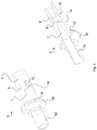
- Fig. 3 shows two detailed perspective views of the venturi tube 5 of the first embodiment.
- the venturi tube 5 is provided for causing a low pressure and/or vacuum due to the venturi effect at a venturi opening 15 as lateral opening of the venturi tube 5 to draw in the fuel vapor F1.
- the venturi tube 5 comprises an inlet portion 7 for receiving pressurized air F2 from the turbocharger 3. It is understood that F2 is a portion of the pressurized air supplied to the combustion engine of a vehicle. One may contemplate of a bypass channel from the outlet of the turbocharger 3 to the inlet tube 19 as explained below.
- the inlet portion 7 has a tapered cross section in the direction of a pressurized air flow for forming a nozzle 14. The inlet portion having the tapered cross section causes the generation of a low pressure and/or vacuum at the nozzle 14 due to the venturi effect.
- the venturi tube 5 further comprises an expansion portion 8 attached to the inlet portion 7.
- the expansion portion 8 comprises the venturi opening 15 as lateral opening.
- the low pressure and/or vacuum generated at the nozzle 14 is provided at the venturi opening 15 to draw in fuel vapor F1, F1' from the fuel vapor supply 4 through the venturi opening 15 into the expansion portion 8.
- the fuel vapor F1, F1' is drawn in from the fuel vapor supply 4 into the venturi tube 5 through a fuel vapor pipe 11 which will be described later.
- the expansion portion 8 is configured to let the drawn in fuel vapor F1 into the venturi tube 5 and to mix the drawn in fuel vapor F1 with the expanded pressurized air supplied through the inlet portion 7.
- the expansion portion 8 has a larger cross section than the nozzle 14 of the inlet portion 7.
- the venturi tube 5 further comprises an outlet portion 9 attached to the expansion portion 8 for supplying a mixture F12', F3 of drawn in fuel vapor and expanded pressurized air to the turbocharger 3.
- the outlet portion 9 has a cross section that is increasing in the direction of the flow of the mixture F12'. The flow is considered to be in parallel to an axial direction of the nozzle element 5. The axial direction can be seen along the longitudinal extension. Hence, the outlet portion 9 widens in the direction of the flow of the mixture F12'. Having the outlet portion 9 with the increasing cross section allows a smooth flow of the mixture F12' from the expansion portion 8 and through the outlet portion 9. This further improves the flow of the fuel vapor F1, F1', F12' through the venturi tube 5.
- the dual purge device 2 comprises further an air duct part 6 for supplying atmospheric air F5 and said mixture F3 to the turbocharger 3.
- the air duct part 6 is a portion of the intake pipe of the turbocharger 3. Furthermore, the air duct part 6 is part of a housing not shown in Figs. 1 to 3 .
- the air duct part 6 comprises a receiving section 12 for receiving the venturi tube 5 though an opening in the housing and/or air duct part 6, as described later.
- the air duct part 6 comprises a main duct 10 for receiving the atmospheric air F5.
- the main duct 10 receives the atmospheric air F5 for example from an air filter.
- the main duct 10 is furthermore configured to supply the atmospheric air F5 together with the mixture F3 supplied from the venturi tube 5 to the turbocharger 3.
- the air duct part 6 further comprises the fuel vapor pipe 11, as fuel vapor section, for receiving fuel vapor F1 from the fuel vapor supply 4 and for providing the fuel vapor F1' to the venturi tube 5.
- the fuel vapor pipe 11 comprises a tube-shaped fuel vapor inlet 28 and a connecting channel 18.
- the tube-shaped fuel vapor inlet 28 is configured for connection with the fuel vapor supply 4.
- the connecting channel 18 connects the tube-shaped fuel vapor inlet 28 and the venturi tube 5.
- the connecting channel 18 is arranged perpendicular to a longitudinal axis of the venturi tube 5.
- the connecting channel 18 is communicatively connected to the venturi opening 15 of the venturi tube 5 for supplying the fuel vapor F1' supplied from the tube-shaped fuel vapor inlet 28 through the venturi opening 15 to the expansion portion 8 of the venturi tube 5.
- the venturi tube 5 draws in fuel vapor F1' from the connecting channel 18 through the venturi opening 15.
- the air duct part 6 is formed by injection molding of plastic material, e.g. thermoplastics.
- the fuel vapor pipe 11 comprises a cap 22 to close a hole necessary for demolding the channel 18 during the molding of the air duct part 6, in particular the fuel vapor pipe 11.
- the cap is, for example, welded to the distal end of the channel 18.
- the air duct part 6 further comprises the receiving section 12 for receiving and accommodating the venturi tube 5, as described in the following.
- the venturi tube 5 further comprises a tube portion 19 with a constant internal cross section attached to inlet portion 7 and extending out of the receiving section 12.
- the tube portion 19 and the venturi tube 5 are monolithic, in particular formed by injection molding.
- the tube portion 19 and the venturi tube 5 are coaxially arranged, which facilitates the assembly of the dual purge device 2.
- the receiving section 12 accommodates the venturi tube 5 such that the inlet portion 7, the expansion portion 8 and the outlet portion 9 are fully accommodated by the receiving section 12 and such that the tube portion 19 extends out of the receiving section 12 and can be accessed. Furthermore, the venturi tube 5 and the receiving section 12 abut against each other in an axial direction at an externally protruding shoulder 34 of the tube portion 19. Thereby, the venturi tube 5 is held in place within the receiving section 12 such that the venturi opening 15 of the venturi tube 5 is arranged at the connecting channel 18 of the fuel vapor pipe 11. An efficient flow of the fuel vapor F1' from the connecting channel 18 to the inside of the venturi tube 5 is provided.
- the venturi tube 5 is fixedly coupled to the receiving portion 12 of the air duct part 6.
- the tube portion 19 comprises an exterior circumferential coupling element 16, and the receiving portion 12 comprises a corresponding coupling element 17.
- the coupling element 16 and the corresponding coupling element 17 are configured to implement a snap or catch coupling or in an alternative embodiment configured to be welded together, in particular be spin welded.
- the air duct part 6 further comprises an outlet section 13 attached to the receiving section 12.
- the outlet section 13 comprises a tube-shaped channel 29 arranged perpendicular to the longitudinal axis of the venturi tube 5.
- the tube-shaped channel 29 is communicatively connected to the outlet portion 9 of the venturi tube 11.
- the tube-shaped channel 29 is furthermore communicatively coupled to the main duct 10 of the air duct part 6.
- the fuel vapor F1 is supplied from the fuel vapor supply 4 to the tube-shaped fuel vapor inlet 28 of the fuel vapor pipe 11.
- the fuel vapor F1' is supplied from there to the connecting channel 18 and further to the venturi opening 15 of the venturi tube 5.
- the venturi tube 5 generates a low pressure and/or vacuum, as described, to draw in the fuel vapor F1' supplied through the connecting channel 18 into the expansion portion 8 of the venturi tube 5.
- the fuel vapor F1' is mixed with the expanded pressurized air F2' supplied through the inlet portion 7.
- the mixture F12' of fuel vapor F1' and expanded pressurized air F2' is generated.
- the mixture F12' is then supplied through the outlet portion 9 of the venturi tube 5 to the outlet section 13 of the air duct part 6.
- the mixture F3 supplied by the outlet section is then supplied to into the air supplied to an internal combustion engine upstream the turbocharger 3.
- a second embodiment of the dual purge device 2 will be described in the following with respect to Figs. 4 and 5 .
- Fig. 4 shows two cross sectional views of a dual purge device 2' according to the second embodiment.
- the right drawing of Fig. 4 shows the dual purge device 2' in a top view (i.e. a view perspective similar to that of Fig. 2 ).
- the left drawing of Fig. 4 shows the dual purge device 2' in a cross sectional view taken along a line A-A denoted in the right panel of Fig. 4 .
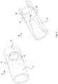
- Fig. 5 shows two perspective views of a venturi tube 5' of the dual purge device 2' of Fig. 4 .
- the second embodiment is similar to the first embodiment apart from the configuration of the venturi tube 5' and a receiving portion 12' of an air duct part 6'.
- the venturi tube 5' of the second embodiment does not comprise a portion, as the tube portion 19, extending from the receiving section 12'.
- the venturi tube 5' of the second embodiment comprises an inlet portion 7' for receiving pressurized air F2 from the turbocharger 3.
- the inlet portion 7' has a tapered cross section in the direction of a pressurized air flow for forming a nozzle 14'.
- the inlet portion having the tapered cross section causes the generation of a low pressure and/or vacuum at the nozzle 14' due to the venturi effect.
- the venturi tube 5' further comprises an expansion portion 8' attached to the inlet portion 7'.
- the expansion portion 8' comprises a venturi opening 15' as lateral opening.
- the low pressure and/or vacuum generated at the nozzle 14' is provided at the venturi opening 15' to draw in fuel vapor F1, F1' from the fuel vapor supply 4 through the venturi opening 15' into the expansion portion 8' of the venturi tube 5'.
- the fuel vapor pipe 11' is similar to the fuel vapor pipe 11 of the first embodiment.
- the expansion portion 8' is configured to let the drawn in fuel vapor F1' into the venturi tube 5' and to mix the drawn in fuel vapor F1' with the expanded pressurized air F2' supplied through the inlet portion 7'.
- the expansion portion 8' has a larger cross section than the nozzle 14' of the inlet portion 7'.
- the venturi tube 5' further comprises an outlet portion 9' attached to the expansion portion 8' for supplying a mixture F12' of drawn in fuel vapor F1' and expanded pressurized air F2' to an outlet section 13' of the air duct part 6'.
- the mixture F3 is then further supplied to the turbocharger 3.
- the outlet portion 9' has a cross section that is increasing in the direction of the flow of the mixture F12'. Hence, the outlet portion 9' widens in the direction of the flow of the mixture F12'. Having the outlet portion 9' with the increasing cross section allows a smooth flow of the mixture F12' from the expansion portion 8' and through the outlet portion 9'. This further improves the flow of the fuel vapor F1, F1' F12' through the venturi tube 5'.
- the air duct part 6' further comprises a receiving section 12' for accommodating the venturi tube 5', as described in the following.
- the receiving section 12' of the second embodiment has an internal constant cross section. Furthermore, the receiving section 12' has internally protruding shoulder 33.
- the internally protruding shoulder 33 is in particular at least particularly circumferentially formed at the inside of the receiving section 12'.
- the receiving section 12' accommodates the venturi tube 5' such that the venturi tube 5' is fully accommodated in the interior of receiving section 12'. In particular, no portion of the venturi tube 5' extends out of the receiving section 12'.
- venturi tube 5' and the receiving section 12' abut against each other in an axial direction at the internally protruding shoulder 33 of the receiving section 12'.
- the venturi tube 5' is inserted into the receiving section 12' it is inserted until it abuts against the internally protruding shoulder 33.
- the venturi tube 5' By abutting of the venturi tube 5' and the receiving section 12', the venturi tube 5' is hold in place within the receiving section 12' such that the venturi opening 15' of the venturi tube 5' is arranged at the connecting channel 18' of the fuel vapor pipe 11'.
- an efficient flow of the fuel vapor F1' from the connecting channel 18 through the venturi opening 15' into the expansion portion 8' is provided.
- the housing 20 of the air duct part 6 and its elements are described in the following with respect to Figs. 6 to 9 .
- the housing 20, as shown in Figs. 8 and 9 comprises a first housing element 20a and a second housing element 20b.
- the first housing element 20a and the second housing element 20b are each formed by injection molding and are fixedly coupled to each other, e.g. welded.
- the housing 20 comprises an air inlet port 30 for taking in atmospheric air F5 for example through an air filter.
- the housing 20 comprises further an air outlet port 31 for supplying the atmospheric air F5 and said mixture F3 to an air duct upstream an inlet 24 of the turbocharger 3.
- the main duct 10 connects the air inlet port 30 and the air outlet port 31 with each other within the housing 20.
- the housing 20 further comprises an insertion opening 32 for inserting the venturi tube 5 into the receiving section 12.
- the insertion opening 32 is an opening of the receiving section 12, as illustrated in in the left drawing of Fig. 2 .
- the housing 20 further comprises the tube-shaped fuel vapor inlet 28 for taking in fuel vapor F1 from the fuel vapor supply 4 and guiding the vapor through the channel 18 to the venture nozzle 14.
- the housing 20 further comprises a resonator volume 23 enclosed by walls of the main duct 10, the receiving section 12 and the outlet section 13, as shown in Fig. 8 .
- a resonator volume 23 enclosed by walls of the main duct 10, the receiving section 12 and the outlet section 13, as shown in Fig. 8 .
- Fig. 1 For a further illustration of the resonator volume 23, it is also referred to Fig. 1 .
- a resonator volume can be integrated in the housing 20 and be connected acoustically to the main duct 10.
- the resonator volume can be enclosed by a first housing element 20a and a second housing element 20b beside or surrounding the main duct 10.
- the housing 20 further comprises a cover element 21, 21' attached to the housing 20 for at least partially covering the receiving section 12, the connecting channel 18 and the tube-shaped fuel vapor inlet 28.
- the cover element 21, 21' is configured for protecting the covered parts, i.e. at least part of the receiving section 12, the connecting channel 18 and the tube-shaped fuel vapor inlet 28.
- the cover element 21, 21' is in particular configured for protecting the venturi tube 5 accommodated in the insertion section 12.
- Fig. 6 and 7 show a first embodiment of the cover element 21.
- the cover element 21 has a box shape with lateral opening for receiving a corresponding plate 27 that is explained below.
- Fig. 7 shows the cover element 21 with a cutout into its top portion for illustration. The cutout into the top portion reveals for illustration purposes how the receiving section 12, the connecting channel 18 and the tube-shaped fuel vapor inlet 28 are covered by the cover element 21.
- the cover element 21 comprises a flange 27' or opening to receive a support plate 27.
- the support plate 27 supports the receiving section 12 and the tube-shaped fuel vapor inlet 28.
- the oval lateral opening of the cover element 21 is closed in an assembled state by the support plate 27.
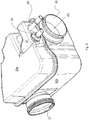
- Fig. 8 and 9 show a second embodiment of the cover element 21'.
- Fig. 8 shows the housing 20 before the cover element 21' is mounted.
- Fig. 9 shows the housing 20 with the mounted cover element 21'.
- the cover element 21' comprises half-round openings 36 to partially encompass the receiving section 12 and the tube-shaped fuel vapor inlet 28.
- Fig. 10 shows an air intake system 1 for a turbocharged internal combustion engine.
- the air intake system 1 comprises a turbocharger 3 for compressing, i.e. pressurizing, atmospheric air.
- the turbocharger 3 comprises an inlet 24 for being supplied with atmospheric air F5 which has been filtered upstream by an air cleaner.
- the turbocharger 3 further comprises an outlet 25.
- the turbocharger 3 is connected at its outlet 25 to an internal combustion engine 35 for supplying the pressurized air F5' together with said mixture F3 to the internal combustion engine 35.
- the air intake system 1 further comprises a fuel vapor supply 4 for fuel vapor F1.
- the air intake system 1 further comprises a purge valve 26.
- the air intake system 1 further comprises the dual purge device 2 as described above. Aspects and embodiments described with respect to the dual purge device 2 also apply mutatis mutandis to the air intake system 1 including the respective dual purge device 2.
- the air outlet port 31 of the air duct 10 of the dual purge device 2 is connected to the inlet 24 of the turbocharger 3 by an air duct.
- the inlet portion 7 of the venturi tube 5 of the dual purge device 2 is connected to the outlet 25 of the turbocharger 3 or downstream of the turbocharger for directing pressurized air F2 from the outlet 25 of the turbocharger 3 to the inlet portion 7 of the venturi tube 5.
- the tube-shaped fuel vapor inlet 28 of the dual purge device 2 is connected to the fuel vapor supply 4 via the purge valve 26.
- the dual purge device can be mounted in vehicle having a combustion engine, e.g. a passenger car, a commercial vehicle, or a farm vehicle.
- a combustion engine e.g. a passenger car, a commercial vehicle, or a farm vehicle.
- the dual purge device can be mounted at stationary engines like power units or other.
Landscapes
- Engineering & Computer Science (AREA)
- Chemical & Material Sciences (AREA)
- Mechanical Engineering (AREA)
- General Engineering & Computer Science (AREA)
- Combustion & Propulsion (AREA)
- Chemical Kinetics & Catalysis (AREA)
- Physics & Mathematics (AREA)
- Fluid Mechanics (AREA)
- Dispersion Chemistry (AREA)
- Supplying Secondary Fuel Or The Like To Fuel, Air Or Fuel-Air Mixtures (AREA)
Abstract
A fuel vapour purge device (2, 2') for a charger (3) in an air intake system (1) of a combustion engine, the fuel vapor purge device (2, 2') comprises an integrally formed nozzle element (5, 5') having an inlet portion (7, 7') for receiving pressurized air (F2) from the charger (3), wherein the inlet portion (7, 7') has a decreasing cross section in the direction of a pressurized air flow (F2) for forming a nozzle (14, 14'), an expansion portion (8, 8') attached to the inlet portion (7, 7'), wherein the expansion portion (8, 8') comprises a lateral opening (15, 15') for drawing in fuel vapor (F1) from a fuel vapor supply (4) into the expansion portion (8, 8'), and an outlet portion (9, 9') attached to the expansion portion (8, 8') for supplying a mixture (F3) of expanded pressurized air (F2) and the drawn in fuel vapor (F1) to the charger (3). The device further comprises an air duct part (6, 6') for supplying atmospheric air (F5) and said mixture (F3) to the charger (3). The air duct part (6, 6') includes a main duct (10, 10') for receiving the atmospheric air (F5) and combining the atmospheric air (F5) and said mixture (F3), a fuel vapor section (11, 11') for receiving the fuel vapor (F1) from the fuel vapor supply (4), wherein the fuel vapor section (11, 11') is coupled to the lateral opening (15, 15'), a receiving section (12, 12') for accommodating the nozzle element (5,5'), and an outlet section (13, 13') coupled to the outlet portion (9, 9') of the nozzle element (5, 5'), wherein the outlet section (13, 13') is communicatively coupled to the main duct (10, 10').
Description
- This disclosure relates to a dual purge device for a charger in an air intake system of a combustion engine and an air intake system.
- Combustion engines for vehicles, in particular charged combustion engines, are sometimes provided with a dual purge system for drawing in fuel vapor for fuel tank evaporation.
US 2018/0036956 A1 disclosed an ejector used to purge the carbon canister in a pressure-charged engine with a venturi insert disposed in a narrowing tube to induce a flow. Furthermore, an ejctor formed by two pieces that are welded together at an interface of the two parts to form an angled weld joint. - In a charged engine, often a positive pressure, e.g. pressure higher than atmospheric pressure, exists in the intake manifold making the purge flow of fuel vapor difficult and/or impossible. In a dual purge device a venturi nozzle is used, which is supplied with pressurized air from the charger in order to generate a pressure gradient and, thus, a flow of the fuel vapor through the venturi nozzle.
- In view of the above, it is an object of the present invention to provide an improved dual purge device for an air intake system. It is a further object to provide an improved air intake system comprising a dual purge system.
- Accordingly, a dual purge device for a charger, in particular a turbocharger or an e-booster or compressor, in an air intake system of a combustion engine is provided. The dual purge device comprises an integrally formed nozzle element. The nozzle element comprises an inlet portion for receiving pressurized air from a charger. The inlet portion has a tapered cross section in the direction of a pressurized air flow for forming a nozzle. The nozzle element further comprises an expansion portion attached to the inlet portion. The expansion portion comprises a lateral opening for drawing in fuel vapor from a fuel vapor supply into the expansion portion. The nozzle element further comprises an outlet portion attached to the expansion portion for supplying a mixture of expanded pressurized air and the drawn in fuel vapor to the charger. The dual purge device further comprises an air duct part for supplying atmospheric air and said mixture to the charger. The air duct part comprises a main duct for receiving the atmospheric air and combining the atmospheric air and said mixture. The air duct part further comprises a fuel vapor section for receiving fuel vapor from the fuel vapor supply. The fuel vapor section is coupled to the lateral opening. The air duct part further comprises a receiving section for accommodating the nozzle element. The air duct part further comprises an outlet section coupled to the outlet portion of the nozzle element, wherein the outlet section is communicatively coupled to the main duct.
- The venturi nozzle of the nozzle element in the dual purge device causes the generation of a low pressure and/or vacuum at the nozzle due to the venturi effect. In particular, the inlet portion of the venturi nozzle causes the generation of a low pressure and/or vacuum at the nozzle due to the venturi effect. The inlet portion may have a tube shape.
- The lateral opening of the nozzle element is configured to provide the generated low pressure and/or vacuum to the fuel vapor section. The generated low pressure and/or vacuum causes the fuel vapor supplied through the fuel vapor section to be drawn in into the nozzle element. In particular, the fuel vapor is drawn in into the expansion portion of the nozzle element.
- The expansion portion is, in particular, a portion for drawing in the fuel vapor into the nozzle element and for mixing the drawn in fuel vapor and the expanded pressurized air, i.e. the pressurized air passed through the inlet portion, with each other. The expansion portion has a larger cross section than the nozzle of the inlet portion. The expansion portion comprises the lateral opening of the nozzle element.
- In embodiment the lateral opening has a circular shape and is adapted to be coupled to an attached tube or channel.
- Having the expansion portion allows to efficiently draw in the fuel vapor. Having the expansion portion allows to generate a large flow of drawn in fuel vapor. In particular, the fuel vapor can be drawn in freely through the lateral opening into a wide space with respect to the pre-nozzle volume of the inlet portion provided by the expansion portion. In particular, the fuel vapor can be drawn in without encountering an obstacle. The expansion portion allows to better mix the drawn in fuel vapor and the expanded pressurized air. Thus, the dual purge device with the expansion portion provides an improved flow characteristic of the drawn in fuel vapor. In particular, the dual purge device with the expansion portion provides an improved flow of the fuel vapor through the nozzle element. Hence, a dual purge device with an improved purge flow is provided. Hence, a fuel efficiency of the combustion engine can be improved.
- The outlet portion of the nozzle element can have a tube shape.
- Fuel vapor can be a mixture of air and fuel, in particular of air and gaseous fuel or fuel droplets. Fuel vapor is generated by purging air through a canister of a fuel tank. Applying a dual fuel system to a charged engine requires often a dual purge system to draw in the fuel vapor.
- The receiving section of the air duct part is configured for receiving and accommodating the nozzle element, in particular for holding the nozzle element within the receiving section in place.
- In embodiments, the nozzle element is welded, press fitted, form fitted, glued and/or otherwise bonded in the air duct part that itself can be part of housing.
- Pressurized air (e.g. turbo-charged air) from the charger (e.g. turbocharger) is in particular air compressed by a turbocharger or compressor in general. Expanded pressurized air is pressurized air that has passed through the nozzle of the inlet portion of the nozzle element.
- According to further embodiments, the nozzle element has a constant outer cross section along the inlet portion, the expansion portion and the outlet portion.
- Thereby, the nozzle element can be accommodated in the receiving section having a constant inner cross section, e.g. a tube.
- According to further embodiments, the inlet portion, the expansion portion and the outlet portion are coaxially arranged.
- A coaxial arrangement of inlet portion, the expansion portion and the outlet portion allows for an efficient flow of the pressurized air through the nozzle element.
- According to further embodiments, the expansion portion has a cylindrical shape.
- The expansion portion may have for example an inner cylindrical shape and/or an outer cylindrical shape. For an expansion portion with an inner cylindrical shape, the base area of the cylindrical shape may comprise the nozzle formed by the inlet portion.
- According to further embodiments, the outlet portion has an increasing cross section in the direction of a flow of the mixture.
- The outlet portion has a cross section that is increasing in the direction of the flow of the mixture of drawn in fuel vapor and expanded pressurized air. Hence, the inner volume of the outlet portion widens in the direction of the flow of the mixture of drawn in fuel vapor and expanded pressurized air.
- Having the outlet portion with the increasing cross section allows a smooth flow of the mixture of drawn in fuel vapor and expanded pressurized air from the expansion portion to the outlet section of the air duct part. Hence, the outlet portion with the increasing cross section further improves the flow of the fuel vapor through the nozzle element.
- According to further embodiments, the nozzle element and/or the air duct part is formed by injection molding, in particular by injection molding of plastic material, in particular thermoplastic or thermoset material.
- Thereby, the nozzle element and/or the air duct part can be easily and efficiently manufactured. Thus, manufacturing costs can be saved. Furthermore, the nozzle element can be fixedly coupled to the air duct part in an easy manner avoiding welding, for example by a snap or catch coupling. In particular, the geometric configuration of the nozzle element and the air duct part allows for injection molding.
- According to further embodiments, the nozzle element and the receiving section abut against each other in an axial direction at an internally protruding shoulder of the receiving section or an externally protruding shoulder of the nozzle element.
- By this abutting of the nozzle element and the receiving section, the nozzle element is kept immobile within the receiving section. Furthermore, by this abutting of the nozzle element and the receiving section the nozzle element is hold in place within the receiving section. In particular, the nozzle element is hold in place within the receiving section such that the lateral opening of the nozzle element is arranged at the fuel vapor section. Thereby, an advantageous flow of the fuel vapor from the fuel vapor section to the nozzle element is possible.
- In embodiments, the nozzle element and the receiving section abut against each other in an axial direction at an internally protruding shoulder of the receiving section. In particular, the nozzle element is inserted into the receiving section until it abuts against the internally protruding shoulder of the receiving section.
- In embodiments, the nozzle element and the receiving section abut against each other in an axial direction at an externally protruding shoulder of the nozzle element. In particular.
- In embodiments, the nozzle element can be held in place by clamping the element axially between shoulders of the nozzle element and/or the air duct part.
- According to further embodiments, the nozzle element further comprises a tube portion with a constant cross section attached to inlet portion and extending out of the receiving section.
- In particular, the tube portion has a constant internal cross section. The tube portion extending out of the receiving section allows a handling of the nozzle element by handling the tube portion. The tube portion can be used as a port or connector and may include a flange for abutting to a rim of a receiving opening in the air duct part.
- The tube portion and the nozzle element may be one piece, or monolithic. The tube portion and the nozzle element are preferentially formed by injection molding allowing their easy manufacturing.
- In embodiments with the nozzle element comprising the tube portion, the nozzle element and the receiving section may abut against each other in an axial direction at an externally protruding shoulder of the tube portion of the nozzle element.
- In embodiments, the tube portion and the nozzle element are coaxially arranged. By having the coaxial arrangement of the tube portion and the nozzle element, the flow direction of pressurized air within the tube portion is parallel to the flow direction within the nozzle element.
- According to further embodiments, the tube portion and/or the receiving portion comprises corresponding coupling elements for fixedly coupling the nozzle element to the air duct part.
- In particular, the tube portion and/or the receiving portion comprises corresponding coupling elements for fixedly coupling the nozzle element to the receiving section of the air duct part.
- The corresponding coupling element of the tube portion and/or the corresponding coupling element of the receiving portion may for example be formed circumferential.
- The corresponding coupling element of the tube portion may comprise an exterior coupling element, in particular a hook, stud, bead, snap and/or catch element. The corresponding coupling element of the receiving portion may comprise a recess configured to couple with the coupling element of the tube portion.
- Having a catch or snap coupling of the nozzle element to the air duct part avoids a welding connection between the nozzle element to the air duct part. Having the catch or snap coupling allows to form the nozzle element and the air duct part by injection molding.
- Alternatively or additionally, the coupling between the nozzle element and the air duct part can also be a welding connection, in particular a spin welding connection.
- According to further embodiments, the fuel vapor section comprises a tube-shaped fuel vapor inlet and a connecting channel. The connecting channel is arranged perpendicular to a longitudinal axis of the nozzle element and attached to the lateral opening of the nozzle element.
- The connecting channel is communicatively connected to the lateral opening of the nozzle element for supplying the fuel vapor supplied from the tube-shaped fuel vapor inlet through the lateral opening to the expansion portion of the nozzle element.
- Having the connecting channel arranged perpendicular to the longitudinal axis of the nozzle element and attached to the lateral opening of the nozzle element allows an efficient drawing in of fuel vapor into the nozzle element.
- In embodiments, the tube-shaped fuel vapor inlet and the longitudinal axis of the nozzle element are arranged in parallel to each other. In other embodiments, the tube-shaped fuel vapor inlet and the longitudinal axis of the nozzle element are perpendicular to each other. This allows a flexibility of the orientation of tube-shaped fuel vapor inlet relative to the nozzle element. Thus, a flexible arrangement with respect to packaging constraints.
- Alternative to the perpendicular arrangement of the connecting channel relative to the longitudinal axis of the nozzle element, the connecting channel can be arranged angled with respect to the longitudinal axis of the nozzle element with an angle in the range of 30 to less than 90 degrees.
- According to further embodiments, the outlet section comprises a tube-shaped channel arranged perpendicular to the longitudinal axis of the nozzle element.
- The tube-shaped channel provides a fluid connection from the nozzle element and the main duct.
- According to further embodiments, the air duct part comprises a housing. The housing comprises an air inlet port and an air outlet port for the atmospheric air and the mixture. The main duct connects the air inlet port and the air outlet port. The housing further comprises an insertion opening for inserting the nozzle element into the receiving section. The housing comprises the tube-shaped fuel vapor inlet.
- The air inlet port and/or the air outlet port may be pipe ends and/or duct connections of the main duct.
- The insertion opening may be an opening of the insertion section for accommodating the nozzle element.
- Having the housing allows to at least partially encase the main duct, the receiving section, and the outlet section allowing to protect these elements.
- According to further embodiments, the dual purge device further comprises a cover element attached to the housing for at least partially covering the receiving section, the connecting channel and the tube-shaped fuel vapor inlet.
- Having the housing allows to at least partially encase the receiving section, the connecting channel, the tube-shaped fuel vapor inlet and the tube portion allowing to protect these elements for example against shocks.
- Having the cover allows in particular to protect the nozzle element within the receiving section for example against shocks.
- According to further embodiments, the housing comprises a resonator volume at least partially enclosed by walls of the main duct, the receiving section and/or the outlet section.
- The walls of the main duct, the receiving section and/or the outlet section may form a (partly) closed hollow section comprising the resonator volume.
- Having the resonator volume allows to reduce noise of the dual purge system and/or the air intake system.
- According to another aspect of this disclosure an air intake system for a charged, in particular turbocharged, internal combustion engine is provided. The air intake system comprises a charger, in particular a turbocharger or a compressor or an e-booster, with an inlet and an outlet. The charger being connected at its outlet to an internal combustion engine to provide pressurized air to the internal combustion engine. The air intake system further comprises a fuel vapor supply for fuel vapor. The air intake system comprises the dual purge device as described above or below with respect to embodiments. An air outlet port of the air duct is connected to the inlet of the charger. The inlet portion is connected to the outlet of the charger. The fuel vapor section is connected to the fuel vapor supply.
- Aspects and embodiments described with respect to the dual purge device also apply mutatis mutandis to the air intake system including a respective dual purge device.
- The dual purge device is connected to the fuel vapor supply for drawing in fuel vapor. In particular, the fuel vapor section can be connected to the fuel vapor supply via a purge valve.
- The dual purge device is connected to the outlet of the charger for directing pressurized air from the charger to the dual purge device.
- The dual purge device is configured for generating a mixture of the drawn in fuel vapor and the pressurized air and for supplying the mixture to the inlet of the charger such that the inlet of the charger receives in addition to atmospheric air also the mixture.
- The fuel vapor supply may comprises a fuel tank and an air filter.
Further possible implementations or alternative solutions of the dual purge device and the air intake system also encompass combinations - that are not explicitly mentioned herein - of features described above or below with regard to the embodiments. The person skilled in the art may also add individual or isolated aspects and features to the most basic form of the invention - Further embodiments, features and advantages of the present dual purge device will become apparent from the subsequent description and dependent claims, taken in conjunction with the accompanying drawings, in which:
- Fig. 1
- shows a perspective view of a cross sectional cut of a dual purge device according to a first embodiment;
- Fig. 2
- shows two cross sectional views of the dual purge device of
Fig. 1 ; - Fig. 3
- shows two perspective views of a venturi tube of the dual purge device of
Fig. 1 ; - Fig. 4
- shows two cross sectional views of a dual purge device according to a second embodiment;
- Fig. 5
- shows two perspective views of a venturi tube of the dual purge device of
Fig. 4 . - Fig. 6
- shows a perspective view of a dual purge device of
Fig. 1 and a support plate; - Fig. 7
- shows a perspective view of the dual purge device from
Fig.1 and part of a housing; - Fig. 8
- shows a perspective view of the dual purge of
Fig. 1 and the housing and a cover as a single part; - Fig. 9
- shows a perspective view of the dual purge device and the housing from
Fig. 8 with an assembled cover; and - Fig. 10
- shows an air intake system comprising the dual purge device from
Fig. 1 . - In the Figures, like reference numerals designate like or functionally equivalent elements, unless otherwise indicated.
- A first embodiment of the
dual purge device 2 will be described in the following with reference toFigs. 1 to 3 . -
Fig. 1 shows a perspective view of adual purge device 2 according to the first embodiment.Fig. 2 shows two cross sectional views of the dual purge device ofFig. 1 . The right drawing ofFig. 2 shows thedual purge device 2 fromFig.1 when viewed from top. The left drawing ofFig. 2 shows thedual purge device 2 in a cross sectional view taken along a line A-A denoted in the right panel ofFig. 2 . - The
dual purge device 2 is provided for generating a flow of fuel vapor by drawing in fuel vapor F1 to supply it into the air supplied to a charged internal combustion engine, in this embodiment a turbocharged engine. - The
dual purge device 2 includes aventuri tube 5 as a nozzle element.Fig. 3 shows two detailed perspective views of theventuri tube 5 of the first embodiment. Theventuri tube 5 is provided for causing a low pressure and/or vacuum due to the venturi effect at aventuri opening 15 as lateral opening of theventuri tube 5 to draw in the fuel vapor F1. - As can be seen from
Figs. 1 to 3 , theventuri tube 5 comprises aninlet portion 7 for receiving pressurized air F2 from the turbocharger 3. It is understood that F2 is a portion of the pressurized air supplied to the combustion engine of a vehicle. One may contemplate of a bypass channel from the outlet of the turbocharger 3 to theinlet tube 19 as explained below. Theinlet portion 7 has a tapered cross section in the direction of a pressurized air flow for forming anozzle 14. The inlet portion having the tapered cross section causes the generation of a low pressure and/or vacuum at thenozzle 14 due to the venturi effect. - The
venturi tube 5 further comprises anexpansion portion 8 attached to theinlet portion 7. Theexpansion portion 8 comprises theventuri opening 15 as lateral opening. The low pressure and/or vacuum generated at thenozzle 14 is provided at theventuri opening 15 to draw in fuel vapor F1, F1' from thefuel vapor supply 4 through theventuri opening 15 into theexpansion portion 8. Thereby, the fuel vapor F1, F1' is drawn in from thefuel vapor supply 4 into theventuri tube 5 through afuel vapor pipe 11 which will be described later. - The
expansion portion 8 is configured to let the drawn in fuel vapor F1 into theventuri tube 5 and to mix the drawn in fuel vapor F1 with the expanded pressurized air supplied through theinlet portion 7. Theexpansion portion 8 has a larger cross section than thenozzle 14 of theinlet portion 7. Thus, the fuel vapor F1 can be drawn in freely through theventuri opening 15 into a wide space provided by theexpansion portion 8. Hence, a large flow of drawn in fuel vapor F1 can be generated. - The
venturi tube 5 further comprises anoutlet portion 9 attached to theexpansion portion 8 for supplying a mixture F12', F3 of drawn in fuel vapor and expanded pressurized air to the turbocharger 3. Theoutlet portion 9 has a cross section that is increasing in the direction of the flow of the mixture F12'. The flow is considered to be in parallel to an axial direction of thenozzle element 5. The axial direction can be seen along the longitudinal extension. Hence, theoutlet portion 9 widens in the direction of the flow of the mixture F12'. Having theoutlet portion 9 with the increasing cross section allows a smooth flow of the mixture F12' from theexpansion portion 8 and through theoutlet portion 9. This further improves the flow of the fuel vapor F1, F1', F12' through theventuri tube 5. - The
dual purge device 2 comprises further anair duct part 6 for supplying atmospheric air F5 and said mixture F3 to the turbocharger 3. Theair duct part 6 is a portion of the intake pipe of the turbocharger 3. Furthermore, theair duct part 6 is part of a housing not shown inFigs. 1 to 3 . Theair duct part 6 comprises a receivingsection 12 for receiving theventuri tube 5 though an opening in the housing and/orair duct part 6, as described later. - The
air duct part 6 comprises amain duct 10 for receiving the atmospheric air F5. Themain duct 10 receives the atmospheric air F5 for example from an air filter. Themain duct 10 is furthermore configured to supply the atmospheric air F5 together with the mixture F3 supplied from theventuri tube 5 to the turbocharger 3. - The
air duct part 6 further comprises thefuel vapor pipe 11, as fuel vapor section, for receiving fuel vapor F1 from thefuel vapor supply 4 and for providing the fuel vapor F1' to theventuri tube 5. Thefuel vapor pipe 11 comprises a tube-shapedfuel vapor inlet 28 and a connectingchannel 18. The tube-shapedfuel vapor inlet 28 is configured for connection with thefuel vapor supply 4. The connectingchannel 18 connects the tube-shapedfuel vapor inlet 28 and theventuri tube 5. The connectingchannel 18 is arranged perpendicular to a longitudinal axis of theventuri tube 5. The connectingchannel 18 is communicatively connected to theventuri opening 15 of theventuri tube 5 for supplying the fuel vapor F1' supplied from the tube-shapedfuel vapor inlet 28 through theventuri opening 15 to theexpansion portion 8 of theventuri tube 5. Theventuri tube 5 draws in fuel vapor F1' from the connectingchannel 18 through theventuri opening 15. - The
air duct part 6 is formed by injection molding of plastic material, e.g. thermoplastics. Thefuel vapor pipe 11 comprises acap 22 to close a hole necessary for demolding thechannel 18 during the molding of theair duct part 6, in particular thefuel vapor pipe 11. The cap is, for example, welded to the distal end of thechannel 18. - The
air duct part 6 further comprises the receivingsection 12 for receiving and accommodating theventuri tube 5, as described in the following. - The
venturi tube 5 further comprises atube portion 19 with a constant internal cross section attached toinlet portion 7 and extending out of the receivingsection 12. Thetube portion 19 and theventuri tube 5 are monolithic, in particular formed by injection molding. Thetube portion 19 and theventuri tube 5 are coaxially arranged, which facilitates the assembly of thedual purge device 2. - The receiving
section 12 accommodates theventuri tube 5 such that theinlet portion 7, theexpansion portion 8 and theoutlet portion 9 are fully accommodated by the receivingsection 12 and such that thetube portion 19 extends out of the receivingsection 12 and can be accessed. Furthermore, theventuri tube 5 and the receivingsection 12 abut against each other in an axial direction at an externally protrudingshoulder 34 of thetube portion 19. Thereby, theventuri tube 5 is held in place within the receivingsection 12 such that theventuri opening 15 of theventuri tube 5 is arranged at the connectingchannel 18 of thefuel vapor pipe 11. An efficient flow of the fuel vapor F1' from the connectingchannel 18 to the inside of theventuri tube 5 is provided. - The
venturi tube 5 is fixedly coupled to the receivingportion 12 of theair duct part 6. For this purpose, thetube portion 19 comprises an exteriorcircumferential coupling element 16, and the receivingportion 12 comprises acorresponding coupling element 17. Thecoupling element 16 and the correspondingcoupling element 17 are configured to implement a snap or catch coupling or in an alternative embodiment configured to be welded together, in particular be spin welded. - The
air duct part 6 further comprises anoutlet section 13 attached to the receivingsection 12. Theoutlet section 13 comprises a tube-shapedchannel 29 arranged perpendicular to the longitudinal axis of theventuri tube 5. Thus, the tube-shapedchannel 29 is communicatively connected to theoutlet portion 9 of theventuri tube 11. The tube-shapedchannel 29 is furthermore communicatively coupled to themain duct 10 of theair duct part 6. - In operation of the
dual purge device 2, the fuel vapor F1 is supplied from thefuel vapor supply 4 to the tube-shapedfuel vapor inlet 28 of thefuel vapor pipe 11. The fuel vapor F1' is supplied from there to the connectingchannel 18 and further to theventuri opening 15 of theventuri tube 5. - The
venturi tube 5 generates a low pressure and/or vacuum, as described, to draw in the fuel vapor F1' supplied through the connectingchannel 18 into theexpansion portion 8 of theventuri tube 5. Within theexpansion portion 8, the fuel vapor F1' is mixed with the expanded pressurized air F2' supplied through theinlet portion 7. Thereby, the mixture F12' of fuel vapor F1' and expanded pressurized air F2' is generated. The mixture F12' is then supplied through theoutlet portion 9 of theventuri tube 5 to theoutlet section 13 of theair duct part 6. The mixture F3 supplied by the outlet section is then supplied to into the air supplied to an internal combustion engine upstream the turbocharger 3. - A second embodiment of the
dual purge device 2 will be described in the following with respect toFigs. 4 and5 . -
Fig. 4 shows two cross sectional views of a dual purge device 2' according to the second embodiment. The right drawing ofFig. 4 shows the dual purge device 2' in a top view (i.e. a view perspective similar to that ofFig. 2 ). The left drawing ofFig. 4 shows the dual purge device 2' in a cross sectional view taken along a line A-A denoted in the right panel ofFig. 4 . -
Fig. 5 shows two perspective views of a venturi tube 5' of the dual purge device 2' ofFig. 4 . - The second embodiment is similar to the first embodiment apart from the configuration of the venturi tube 5' and a receiving portion 12' of an air duct part 6'. As will be described in detail in the following, the venturi tube 5' of the second embodiment does not comprise a portion, as the
tube portion 19, extending from the receiving section 12'. - Hereinafter, only those features of the second embodiment will be described which are different from that of the first embodiment. A description of same features will be omitted.
- As can be seen from
Figs. 4 and5 , the venturi tube 5' of the second embodiment comprises an inlet portion 7' for receiving pressurized air F2 from the turbocharger 3. The inlet portion 7' has a tapered cross section in the direction of a pressurized air flow for forming a nozzle 14'. The inlet portion having the tapered cross section causes the generation of a low pressure and/or vacuum at the nozzle 14' due to the venturi effect. - The venturi tube 5' further comprises an expansion portion 8' attached to the inlet portion 7'. The expansion portion 8' comprises a venturi opening 15' as lateral opening. The low pressure and/or vacuum generated at the nozzle 14' is provided at the venturi opening 15' to draw in fuel vapor F1, F1' from the
fuel vapor supply 4 through the venturi opening 15' into the expansion portion 8' of the venturi tube 5'. - Thereby, the fuel vapor F1, F1' is drawn in from the
fuel vapor supply 4 into the venturi tube 5' through a fuel vapor pipe 11'. The fuel vapor pipe 11' is similar to thefuel vapor pipe 11 of the first embodiment. - The expansion portion 8' is configured to let the drawn in fuel vapor F1' into the venturi tube 5' and to mix the drawn in fuel vapor F1' with the expanded pressurized air F2' supplied through the inlet portion 7'. The expansion portion 8' has a larger cross section than the nozzle 14' of the inlet portion 7'. Thus, the fuel vapor F1' can be drawn in freely through the venturi opening 15' into a wide space provided by the expansion portion 8'. Hence, a large flow of drawn in fuel vapor F1' can be generated.
- The venturi tube 5' further comprises an outlet portion 9' attached to the expansion portion 8' for supplying a mixture F12' of drawn in fuel vapor F1' and expanded pressurized air F2' to an outlet section 13' of the air duct part 6'. The mixture F3 is then further supplied to the turbocharger 3. The outlet portion 9' has a cross section that is increasing in the direction of the flow of the mixture F12'. Hence, the outlet portion 9' widens in the direction of the flow of the mixture F12'. Having the outlet portion 9' with the increasing cross section allows a smooth flow of the mixture F12' from the expansion portion 8' and through the outlet portion 9'. This further improves the flow of the fuel vapor F1, F1' F12' through the venturi tube 5'.
- The air duct part 6' further comprises a receiving section 12' for accommodating the venturi tube 5', as described in the following.
- The receiving section 12' of the second embodiment has an internal constant cross section. Furthermore, the receiving section 12' has internally protruding
shoulder 33. The internally protrudingshoulder 33 is in particular at least particularly circumferentially formed at the inside of the receiving section 12'. - The receiving section 12' accommodates the venturi tube 5' such that the venturi tube 5' is fully accommodated in the interior of receiving section 12'. In particular, no portion of the venturi tube 5' extends out of the receiving section 12'.
- The venturi tube 5' and the receiving section 12' abut against each other in an axial direction at the internally protruding
shoulder 33 of the receiving section 12'. During assembly, when the venturi tube 5' is inserted into the receiving section 12' it is inserted until it abuts against the internally protrudingshoulder 33. - By abutting of the venturi tube 5' and the receiving section 12', the venturi tube 5' is hold in place within the receiving section 12' such that the venturi opening 15' of the venturi tube 5' is arranged at the connecting channel 18' of the fuel vapor pipe 11'. Thus, an efficient flow of the fuel vapor F1' from the connecting
channel 18 through the venturi opening 15' into the expansion portion 8' is provided. - The
housing 20 of theair duct part 6 and its elements are described in the following with respect toFigs. 6 to 9 . - The
housing 20, as shown inFigs. 8 and9 , comprises afirst housing element 20a and asecond housing element 20b. Thefirst housing element 20a and thesecond housing element 20b are each formed by injection molding and are fixedly coupled to each other, e.g. welded. - The
housing 20 comprises anair inlet port 30 for taking in atmospheric air F5 for example through an air filter. Thehousing 20 comprises further anair outlet port 31 for supplying the atmospheric air F5 and said mixture F3 to an air duct upstream aninlet 24 of the turbocharger 3. Themain duct 10 connects theair inlet port 30 and theair outlet port 31 with each other within thehousing 20. - The
housing 20 further comprises aninsertion opening 32 for inserting theventuri tube 5 into the receivingsection 12. Theinsertion opening 32 is an opening of the receivingsection 12, as illustrated in in the left drawing ofFig. 2 . - The
housing 20 further comprises the tube-shapedfuel vapor inlet 28 for taking in fuel vapor F1 from thefuel vapor supply 4 and guiding the vapor through thechannel 18 to theventure nozzle 14. - The
housing 20 further comprises aresonator volume 23 enclosed by walls of themain duct 10, the receivingsection 12 and theoutlet section 13, as shown inFig. 8 . For a further illustration of theresonator volume 23, it is also referred toFig. 1 . - Alternatively or additional a resonator volume can be integrated in the
housing 20 and be connected acoustically to themain duct 10. In particular the resonator volume can be enclosed by afirst housing element 20a and asecond housing element 20b beside or surrounding themain duct 10. - The
housing 20 further comprises acover element 21, 21' attached to thehousing 20 for at least partially covering the receivingsection 12, the connectingchannel 18 and the tube-shapedfuel vapor inlet 28. Thecover element 21, 21' is configured for protecting the covered parts, i.e. at least part of the receivingsection 12, the connectingchannel 18 and the tube-shapedfuel vapor inlet 28. Thecover element 21, 21' is in particular configured for protecting theventuri tube 5 accommodated in theinsertion section 12. -
Fig. 6 and7 show a first embodiment of thecover element 21. Thecover element 21 has a box shape with lateral opening for receiving acorresponding plate 27 that is explained below.Fig. 7 shows thecover element 21 with a cutout into its top portion for illustration. The cutout into the top portion reveals for illustration purposes how the receivingsection 12, the connectingchannel 18 and the tube-shapedfuel vapor inlet 28 are covered by thecover element 21. - The
cover element 21 comprises a flange 27' or opening to receive asupport plate 27. As shown inFig. 6 , thesupport plate 27 supports the receivingsection 12 and the tube-shapedfuel vapor inlet 28. As shown inFig. 7 , the oval lateral opening of thecover element 21 is closed in an assembled state by thesupport plate 27. -
Fig. 8 and9 show a second embodiment of the cover element 21'.Fig. 8 shows thehousing 20 before the cover element 21' is mounted.Fig. 9 shows thehousing 20 with the mounted cover element 21'. The cover element 21' comprises half-round openings 36 to partially encompass the receivingsection 12 and the tube-shapedfuel vapor inlet 28. -
Fig. 10 shows anair intake system 1 for a turbocharged internal combustion engine. Theair intake system 1 comprises a turbocharger 3 for compressing, i.e. pressurizing, atmospheric air. The turbocharger 3 comprises aninlet 24 for being supplied with atmospheric air F5 which has been filtered upstream by an air cleaner. The turbocharger 3 further comprises anoutlet 25. The turbocharger 3 is connected at itsoutlet 25 to aninternal combustion engine 35 for supplying the pressurized air F5' together with said mixture F3 to theinternal combustion engine 35. - The
air intake system 1 further comprises afuel vapor supply 4 for fuel vapor F1. Theair intake system 1 further comprises apurge valve 26. - The
air intake system 1 further comprises thedual purge device 2 as described above. Aspects and embodiments described with respect to thedual purge device 2 also apply mutatis mutandis to theair intake system 1 including the respectivedual purge device 2. - The
air outlet port 31 of theair duct 10 of thedual purge device 2 is connected to theinlet 24 of the turbocharger 3 by an air duct. - The
inlet portion 7 of theventuri tube 5 of thedual purge device 2 is connected to theoutlet 25 of the turbocharger 3 or downstream of the turbocharger for directing pressurized air F2 from theoutlet 25 of the turbocharger 3 to theinlet portion 7 of theventuri tube 5. - The tube-shaped
fuel vapor inlet 28 of thedual purge device 2 is connected to thefuel vapor supply 4 via thepurge valve 26. - Although the present invention has been described in accordance with preferred embodiments, it is obvious for the person skilled in the art that modifications are possible in all embodiments. In particular, the dual purge device can be mounted in vehicle having a combustion engine, e.g. a passenger car, a commercial vehicle, or a farm vehicle. One can also contemplate of trains, railway engines, airborn vehicles or boats. Alternatively the dual purge device can be mounted at stationary engines like power units or other.
Claims (15)
- Dual purge device (2, 2') for a charger (3) in an air intake system (1) of a combustion engine, the dual purge device (2, 2') comprising:an integrally formed nozzle element (5, 5') having:an inlet portion (7, 7') for receiving pressurized air (F2) from the charger (3), wherein the inlet portion (7, 7') has a decreasing cross section in the direction of a pressurized air flow (F2) for forming a nozzle (14, 14'),an expansion portion (8, 8') attached to the inlet portion (7, 7'), wherein the expansion portion (8, 8') comprises a lateral opening (15, 15') for drawing in fuel vapor (F1) from a fuel vapor supply (4) into the expansion portion (8, 8'), andan outlet portion (9, 9') attached to the expansion portion (8, 8') for supplying a mixture (F3) of expanded pressurized air (F2) and the drawn in fuel vapor (F1) to the charger (3);an air duct part (6, 6') for supplying atmospheric air (F5) and said mixture (F3) to the charger (3), the air duct part (6, 6') having:a main duct (10, 10') for receiving the atmospheric air (F5) and combining the atmospheric air (F5) and said mixture (F3),a fuel vapor section (11, 11') for receiving the fuel vapor (F1) from the fuel vapor supply (4), wherein the fuel vapor section (11, 11') is coupled to the lateral opening (15, 15'),a receiving section (12, 12') for accommodating the nozzle element (5,5'), andan outlet section (13, 13') coupled to the outlet portion (9, 9') of the nozzle element (5, 5'), wherein the outlet section (13, 13') is communicatively coupled to the main duct (10, 10').
- Dual purge device (2) according to claim 1, wherein the nozzle element (5, 5') has a constant outer cross section along the inlet portion (7, 7'), the expansion portion (8, 8') and the outlet portion (9, 9').
- Dual purge device (2) according to claim 1 or 2, wherein the inlet portion (7, 7'), the expansion portion (8, 8') and the outlet portion (9, 9') are coaxially arranged.
- Dual purge device (2) according to any one of claims 1 to 3, wherein the expansion portion (8, 8') has a cylindrical shape.
- Dual purge device (2) according to any one of claims 1 to 4, wherein the outlet portion (9, 9') has an increasing cross section in the direction of a flow (F12) of the mixture.
- Dual purge device (2) according to any of claims 1 to 5, wherein the nozzle element (5, 5') and the receiving section (12, 12') abut against each other in an axial direction at an internally protruding shoulder (33) of the receiving section (12) or an externally protruding shoulder (34) of the nozzle element (5, 5').
- Dual purge device (2) according to any of claims 1 to 6, wherein the nozzle element (5) further comprises a tube portion (19) with a constant cross section attached to inlet portion (7) and extending out of the receiving section (12).
- Dual purge device (2) according to claim 7, wherein the tube portion (19) and/or the receiving portion (12) comprises a corresponding coupling elements (16, 17) for fixedly coupling the nozzle element (5) to the air duct part (6).
- Dual purge device (2) according to any of claims 1 to 8, wherein the fuel vapor section (11, 11') comprises a tube-shaped fuel vapor inlet (28) and a connecting channel (18, 18'), the connecting channel (18, 18') being arranged perpendicular to a longitudinal axis of the nozzle element (5, 5') and attached to the lateral opening (15, 15') of the nozzle element (5, 5').
- Dual purge device (2) according to any of claims 1 to 9, wherein the tube-shaped fuel vapor inlet (28) and longitudinal axis of the nozzle element (5) are in parallel to each other.
- Dual purge device (2) according to any of claims 1 to 10, wherein the outlet section (13) comprises a tube-shaped channel (29) arranged perpendicular to a longitudinal axis of the nozzle element (5, 5').
- Dual purge device (2) according to claim 10 or 11, wherein the air duct part (6) comprises a housing (20) having:an air inlet port (30) and an air outlet port (31) for the atmospheric air and the mixture (F3), the main duct (10) connecting the air inlet port (31) and the air outlet port (31), andan insertion opening (32) for inserting the nozzle element (5) into the receiving section (12); andthe tube-shaped fuel vapor inlet (28).
- Dual purge device (2) according to claim 12, further comprising a cover element (21) attached to the housing (20) for at least partially covering the receiving section (12), the connecting channel (18) and the tube-shaped fuel vapor inlet (28).
- Dual purge device (2) according to claim 12 or 13, wherein the housing (20) comprises a resonator volume (23) at least partially enclosed by walls of the main duct (10), the receiving section (12) and/or the outlet section (13).
- Air intake system (1) for a charged internal combustion engine, comprising:a charger (3) with an inlet (24) and an outlet (25), the charger (3) being connected at its outlet (25) to an internal combustion engine to provide pressurized air (F2) to the internal combustion engine;a fuel vapor supply (4) for fuel vapor (F1); andthe dual purge device (2) according to any one of claims 1 to 14, wherein an air outlet port (31) of the air duct (10) is connected to the inlet (24) of the charger (3), the inlet portion (7) is connected to the outlet (25) of the charger (3), and the fuel vapor section (11) is connected to the fuel vapor supply (4).
Priority Applications (1)
| Application Number | Priority Date | Filing Date | Title |
|---|---|---|---|
| EP18290044.9A EP3564519A1 (en) | 2018-05-02 | 2018-05-02 | Fuel vapor purge device |
Applications Claiming Priority (1)
| Application Number | Priority Date | Filing Date | Title |
|---|---|---|---|
| EP18290044.9A EP3564519A1 (en) | 2018-05-02 | 2018-05-02 | Fuel vapor purge device |
Publications (1)
| Publication Number | Publication Date |
|---|---|
| EP3564519A1 true EP3564519A1 (en) | 2019-11-06 |
Family
ID=62386302
Family Applications (1)
| Application Number | Title | Priority Date | Filing Date |
|---|---|---|---|
| EP18290044.9A Withdrawn EP3564519A1 (en) | 2018-05-02 | 2018-05-02 | Fuel vapor purge device |
Country Status (1)
| Country | Link |
|---|---|
| EP (1) | EP3564519A1 (en) |
Cited By (1)
| Publication number | Priority date | Publication date | Assignee | Title |
|---|---|---|---|---|
| EP4371655A1 (en) * | 2022-11-21 | 2024-05-22 | Levitronix GmbH | Eductor |
Citations (5)
| Publication number | Priority date | Publication date | Assignee | Title |
|---|---|---|---|---|
| US20070152355A1 (en) * | 2005-12-30 | 2007-07-05 | Hartley John D | Cylindrical insert fluid injector / vacuum pump |
| KR101361357B1 (en) * | 2012-11-15 | 2014-02-10 | 현대자동차주식회사 | Apparatus for purging fuel evaporation gas of hybrid vehicle |
| US20160377038A1 (en) * | 2015-06-24 | 2016-12-29 | Eagle Actuator Components Gmbh & Co. Kg | Ejector and arrangement for use in a motor vehicle having a turbocharger |
| WO2017056833A1 (en) * | 2015-10-01 | 2017-04-06 | 愛三工業株式会社 | Evaporated fuel processing device |
| US20180036956A1 (en) | 2016-08-02 | 2018-02-08 | Ford Global Technologies, Llc | Manufacture of a Compact Ejector System for a Boosted Internal Combustion Engine |
-
2018
- 2018-05-02 EP EP18290044.9A patent/EP3564519A1/en not_active Withdrawn
Patent Citations (5)
| Publication number | Priority date | Publication date | Assignee | Title |
|---|---|---|---|---|
| US20070152355A1 (en) * | 2005-12-30 | 2007-07-05 | Hartley John D | Cylindrical insert fluid injector / vacuum pump |
| KR101361357B1 (en) * | 2012-11-15 | 2014-02-10 | 현대자동차주식회사 | Apparatus for purging fuel evaporation gas of hybrid vehicle |
| US20160377038A1 (en) * | 2015-06-24 | 2016-12-29 | Eagle Actuator Components Gmbh & Co. Kg | Ejector and arrangement for use in a motor vehicle having a turbocharger |
| WO2017056833A1 (en) * | 2015-10-01 | 2017-04-06 | 愛三工業株式会社 | Evaporated fuel processing device |
| US20180036956A1 (en) | 2016-08-02 | 2018-02-08 | Ford Global Technologies, Llc | Manufacture of a Compact Ejector System for a Boosted Internal Combustion Engine |
Cited By (1)
| Publication number | Priority date | Publication date | Assignee | Title |
|---|---|---|---|---|
| EP4371655A1 (en) * | 2022-11-21 | 2024-05-22 | Levitronix GmbH | Eductor |
Similar Documents
| Publication | Publication Date | Title |
|---|---|---|
| US11090594B2 (en) | Filter element comprising two offset outlets in communication with filter inner space, as well| as corresponding housing | |
| US20130152904A1 (en) | Turbo Purge Module For Turbocharged Vehicle | |
| KR102255542B1 (en) | Crankcase ventilating evacuator | |
| CN107676201B (en) | A compact ejector system for boosted internal combustion engines | |
| US20160097315A1 (en) | Silencer | |
| JP6194899B2 (en) | Introducing gas processing device for supercharged engine and evaporative fuel processing device for supercharged engine | |
| US20160377038A1 (en) | Ejector and arrangement for use in a motor vehicle having a turbocharger | |
| JP6112046B2 (en) | Evaporative fuel processing device for supercharged engine | |
| US11092118B2 (en) | Filter housing and filter | |
| US20180112634A1 (en) | Ejector Integrally Formed with an Intake Air Component and a Method to Manufacture | |
| US20180094571A1 (en) | Air Duct Arrangement and Cooler | |
| EP2055921B1 (en) | Charge fluid intake module, charge fluid intake system, charge fluid intake tract, exhaust gas recirculation system, internal combustion engine | |
| CN208996847U (en) | Air inflow noise elimination system and engine | |
| US20050051138A1 (en) | Intake manifold assembly | |
| US10550743B2 (en) | Cylinder head cover and method for producing a cylinder head cover | |
| US20190242335A1 (en) | Air cleaner connecting tube structure | |
| US20080314669A1 (en) | Motorcycle airbox with flow-enhancing shape | |
| US10724482B2 (en) | Air cleaner connecting tube structure | |
| CN107676200B (en) | Manufacturing and installing method of ejector system for boosting internal combustion engine | |
| CN103362702B (en) | Multi-mode air-breathing tuning conduit | |
| CN105464845A (en) | Fuel steam venturi connector and fuel steam discharging control system | |
| US20080236937A1 (en) | Resonator with internal supplemental noise attenuation device | |
| US20240295201A1 (en) | Negative pressure generator and fuel tank ventilation | |
| WO2012028639A1 (en) | Air intake manifold for internal combustion engine | |
| US20200141368A1 (en) | Ejector Integrally Formed with an Intake Air Component and a Method to Manufacture |
Legal Events
| Date | Code | Title | Description |
|---|---|---|---|
| PUAI | Public reference made under article 153(3) epc to a published international application that has entered the european phase |
Free format text: ORIGINAL CODE: 0009012 |
|
| AK | Designated contracting states |
Kind code of ref document: A1 Designated state(s): AL AT BE BG CH CY CZ DE DK EE ES FI FR GB GR HR HU IE IS IT LI LT LU LV MC MK MT NL NO PL PT RO RS SE SI SK SM TR |
|
| AX | Request for extension of the european patent |
Extension state: BA ME |
|
| STAA | Information on the status of an ep patent application or granted ep patent |
Free format text: STATUS: THE APPLICATION IS DEEMED TO BE WITHDRAWN |
|
| 18D | Application deemed to be withdrawn |
Effective date: 20200603 |