EP3564487B1 - Verbundschaufel für gasturbinenmotoren und entsprechendes herstellungsverfahren - Google Patents
Verbundschaufel für gasturbinenmotoren und entsprechendes herstellungsverfahren Download PDFInfo
- Publication number
- EP3564487B1 EP3564487B1 EP19172045.7A EP19172045A EP3564487B1 EP 3564487 B1 EP3564487 B1 EP 3564487B1 EP 19172045 A EP19172045 A EP 19172045A EP 3564487 B1 EP3564487 B1 EP 3564487B1
- Authority
- EP
- European Patent Office
- Prior art keywords
- airfoil
- core
- section
- skins
- fibers
- Prior art date
- Legal status (The legal status is an assumption and is not a legal conclusion. Google has not performed a legal analysis and makes no representation as to the accuracy of the status listed.)
- Active
Links
Images



Classifications
-
- F—MECHANICAL ENGINEERING; LIGHTING; HEATING; WEAPONS; BLASTING
- F04—POSITIVE - DISPLACEMENT MACHINES FOR LIQUIDS; PUMPS FOR LIQUIDS OR ELASTIC FLUIDS
- F04D—NON-POSITIVE-DISPLACEMENT PUMPS
- F04D29/00—Details, component parts, or accessories
- F04D29/26—Rotors specially for elastic fluids
- F04D29/32—Rotors specially for elastic fluids for axial flow pumps
- F04D29/38—Blades
- F04D29/388—Blades characterised by construction
-
- F—MECHANICAL ENGINEERING; LIGHTING; HEATING; WEAPONS; BLASTING
- F01—MACHINES OR ENGINES IN GENERAL; ENGINE PLANTS IN GENERAL; STEAM ENGINES
- F01D—NON-POSITIVE DISPLACEMENT MACHINES OR ENGINES, e.g. STEAM TURBINES
- F01D5/00—Blades; Blade-carrying members; Heating, heat-insulating, cooling or antivibration means on the blades or the members
- F01D5/12—Blades
- F01D5/28—Selecting particular materials; Particular measures relating thereto; Measures against erosion or corrosion
- F01D5/282—Selecting composite materials, e.g. blades with reinforcing filaments
-
- B—PERFORMING OPERATIONS; TRANSPORTING
- B32—LAYERED PRODUCTS
- B32B—LAYERED PRODUCTS, i.e. PRODUCTS BUILT-UP OF STRATA OF FLAT OR NON-FLAT, e.g. CELLULAR OR HONEYCOMB, FORM
- B32B27/00—Layered products comprising a layer of synthetic resin
- B32B27/12—Layered products comprising a layer of synthetic resin next to a fibrous or filamentary layer
-
- B—PERFORMING OPERATIONS; TRANSPORTING
- B32—LAYERED PRODUCTS
- B32B—LAYERED PRODUCTS, i.e. PRODUCTS BUILT-UP OF STRATA OF FLAT OR NON-FLAT, e.g. CELLULAR OR HONEYCOMB, FORM
- B32B27/00—Layered products comprising a layer of synthetic resin
- B32B27/38—Layered products comprising a layer of synthetic resin comprising epoxy resins
-
- B—PERFORMING OPERATIONS; TRANSPORTING
- B32—LAYERED PRODUCTS
- B32B—LAYERED PRODUCTS, i.e. PRODUCTS BUILT-UP OF STRATA OF FLAT OR NON-FLAT, e.g. CELLULAR OR HONEYCOMB, FORM
- B32B5/00—Layered products characterised by the non- homogeneity or physical structure, i.e. comprising a fibrous, filamentary, particulate or foam layer; Layered products characterised by having a layer differing constitutionally or physically in different parts
- B32B5/02—Layered products characterised by the non- homogeneity or physical structure, i.e. comprising a fibrous, filamentary, particulate or foam layer; Layered products characterised by having a layer differing constitutionally or physically in different parts characterised by structural features of a fibrous or filamentary layer
- B32B5/024—Woven fabric
-
- F—MECHANICAL ENGINEERING; LIGHTING; HEATING; WEAPONS; BLASTING
- F02—COMBUSTION ENGINES; HOT-GAS OR COMBUSTION-PRODUCT ENGINE PLANTS
- F02K—JET-PROPULSION PLANTS
- F02K3/00—Plants including a gas turbine driving a compressor or a ducted fan
- F02K3/02—Plants including a gas turbine driving a compressor or a ducted fan in which part of the working fluid by-passes the turbine and combustion chamber
- F02K3/04—Plants including a gas turbine driving a compressor or a ducted fan in which part of the working fluid by-passes the turbine and combustion chamber the plant including ducted fans, i.e. fans with high volume, low pressure outputs, for augmenting the jet thrust, e.g. of double-flow type
- F02K3/06—Plants including a gas turbine driving a compressor or a ducted fan in which part of the working fluid by-passes the turbine and combustion chamber the plant including ducted fans, i.e. fans with high volume, low pressure outputs, for augmenting the jet thrust, e.g. of double-flow type with front fan
-
- F—MECHANICAL ENGINEERING; LIGHTING; HEATING; WEAPONS; BLASTING
- F04—POSITIVE - DISPLACEMENT MACHINES FOR LIQUIDS; PUMPS FOR LIQUIDS OR ELASTIC FLUIDS
- F04D—NON-POSITIVE-DISPLACEMENT PUMPS
- F04D29/00—Details, component parts, or accessories
- F04D29/02—Selection of particular materials
- F04D29/023—Selection of particular materials especially adapted for elastic fluid pumps
-
- F—MECHANICAL ENGINEERING; LIGHTING; HEATING; WEAPONS; BLASTING
- F04—POSITIVE - DISPLACEMENT MACHINES FOR LIQUIDS; PUMPS FOR LIQUIDS OR ELASTIC FLUIDS
- F04D—NON-POSITIVE-DISPLACEMENT PUMPS
- F04D29/00—Details, component parts, or accessories
- F04D29/26—Rotors specially for elastic fluids
- F04D29/32—Rotors specially for elastic fluids for axial flow pumps
- F04D29/325—Rotors specially for elastic fluids for axial flow pumps for axial flow fans
-
- B—PERFORMING OPERATIONS; TRANSPORTING
- B29—WORKING OF PLASTICS; WORKING OF SUBSTANCES IN A PLASTIC STATE IN GENERAL
- B29C—SHAPING OR JOINING OF PLASTICS; SHAPING OF MATERIAL IN A PLASTIC STATE, NOT OTHERWISE PROVIDED FOR; AFTER-TREATMENT OF THE SHAPED PRODUCTS, e.g. REPAIRING
- B29C70/00—Shaping composites, i.e. plastics material comprising reinforcements, fillers or preformed parts, e.g. inserts
- B29C70/04—Shaping composites, i.e. plastics material comprising reinforcements, fillers or preformed parts, e.g. inserts comprising reinforcements only, e.g. self-reinforcing plastics
- B29C70/28—Shaping operations therefor
- B29C70/40—Shaping or impregnating by compression not applied
- B29C70/42—Shaping or impregnating by compression not applied for producing articles of definite length, i.e. discrete articles
- B29C70/46—Shaping or impregnating by compression not applied for producing articles of definite length, i.e. discrete articles using matched moulds, e.g. for deforming sheet moulding compounds [SMC] or prepregs
- B29C70/48—Shaping or impregnating by compression not applied for producing articles of definite length, i.e. discrete articles using matched moulds, e.g. for deforming sheet moulding compounds [SMC] or prepregs and impregnating the reinforcements in the closed mould, e.g. resin transfer moulding [RTM], e.g. by vacuum
-
- B—PERFORMING OPERATIONS; TRANSPORTING
- B29—WORKING OF PLASTICS; WORKING OF SUBSTANCES IN A PLASTIC STATE IN GENERAL
- B29K—INDEXING SCHEME ASSOCIATED WITH SUBCLASSES B29B, B29C OR B29D, RELATING TO MOULDING MATERIALS OR TO MATERIALS FOR MOULDS, REINFORCEMENTS, FILLERS OR PREFORMED PARTS, e.g. INSERTS
- B29K2063/00—Use of EP, i.e. epoxy resins or derivatives thereof, as moulding material
-
- B—PERFORMING OPERATIONS; TRANSPORTING
- B29—WORKING OF PLASTICS; WORKING OF SUBSTANCES IN A PLASTIC STATE IN GENERAL
- B29K—INDEXING SCHEME ASSOCIATED WITH SUBCLASSES B29B, B29C OR B29D, RELATING TO MOULDING MATERIALS OR TO MATERIALS FOR MOULDS, REINFORCEMENTS, FILLERS OR PREFORMED PARTS, e.g. INSERTS
- B29K2307/00—Use of elements other than metals as reinforcement
- B29K2307/04—Carbon
-
- B—PERFORMING OPERATIONS; TRANSPORTING
- B29—WORKING OF PLASTICS; WORKING OF SUBSTANCES IN A PLASTIC STATE IN GENERAL
- B29L—INDEXING SCHEME ASSOCIATED WITH SUBCLASS B29C, RELATING TO PARTICULAR ARTICLES
- B29L2031/00—Other particular articles
- B29L2031/08—Blades for rotors, stators, fans, turbines or the like, e.g. screw propellers
-
- B—PERFORMING OPERATIONS; TRANSPORTING
- B32—LAYERED PRODUCTS
- B32B—LAYERED PRODUCTS, i.e. PRODUCTS BUILT-UP OF STRATA OF FLAT OR NON-FLAT, e.g. CELLULAR OR HONEYCOMB, FORM
- B32B2255/00—Coating on the layer surface
- B32B2255/02—Coating on the layer surface on fibrous or filamentary layer
-
- B—PERFORMING OPERATIONS; TRANSPORTING
- B32—LAYERED PRODUCTS
- B32B—LAYERED PRODUCTS, i.e. PRODUCTS BUILT-UP OF STRATA OF FLAT OR NON-FLAT, e.g. CELLULAR OR HONEYCOMB, FORM
- B32B2255/00—Coating on the layer surface
- B32B2255/26—Polymeric coating
-
- B—PERFORMING OPERATIONS; TRANSPORTING
- B32—LAYERED PRODUCTS
- B32B—LAYERED PRODUCTS, i.e. PRODUCTS BUILT-UP OF STRATA OF FLAT OR NON-FLAT, e.g. CELLULAR OR HONEYCOMB, FORM
- B32B2262/00—Composition or structural features of fibres which form a fibrous or filamentary layer or are present as additives
- B32B2262/10—Inorganic fibres
- B32B2262/106—Carbon fibres, e.g. graphite fibres
-
- B—PERFORMING OPERATIONS; TRANSPORTING
- B32—LAYERED PRODUCTS
- B32B—LAYERED PRODUCTS, i.e. PRODUCTS BUILT-UP OF STRATA OF FLAT OR NON-FLAT, e.g. CELLULAR OR HONEYCOMB, FORM
- B32B2603/00—Vanes, blades, propellers, rotors with blades
-
- F—MECHANICAL ENGINEERING; LIGHTING; HEATING; WEAPONS; BLASTING
- F05—INDEXING SCHEMES RELATING TO ENGINES OR PUMPS IN VARIOUS SUBCLASSES OF CLASSES F01-F04
- F05D—INDEXING SCHEME FOR ASPECTS RELATING TO NON-POSITIVE-DISPLACEMENT MACHINES OR ENGINES, GAS-TURBINES OR JET-PROPULSION PLANTS
- F05D2220/00—Application
- F05D2220/30—Application in turbines
- F05D2220/32—Application in turbines in gas turbines
- F05D2220/323—Application in turbines in gas turbines for aircraft propulsion, e.g. jet engines
-
- F—MECHANICAL ENGINEERING; LIGHTING; HEATING; WEAPONS; BLASTING
- F05—INDEXING SCHEMES RELATING TO ENGINES OR PUMPS IN VARIOUS SUBCLASSES OF CLASSES F01-F04
- F05D—INDEXING SCHEME FOR ASPECTS RELATING TO NON-POSITIVE-DISPLACEMENT MACHINES OR ENGINES, GAS-TURBINES OR JET-PROPULSION PLANTS
- F05D2220/00—Application
- F05D2220/30—Application in turbines
- F05D2220/36—Application in turbines specially adapted for the fan of turbofan engines
-
- F—MECHANICAL ENGINEERING; LIGHTING; HEATING; WEAPONS; BLASTING
- F05—INDEXING SCHEMES RELATING TO ENGINES OR PUMPS IN VARIOUS SUBCLASSES OF CLASSES F01-F04
- F05D—INDEXING SCHEME FOR ASPECTS RELATING TO NON-POSITIVE-DISPLACEMENT MACHINES OR ENGINES, GAS-TURBINES OR JET-PROPULSION PLANTS
- F05D2230/00—Manufacture
- F05D2230/30—Manufacture with deposition of material
- F05D2230/31—Layer deposition
-
- F—MECHANICAL ENGINEERING; LIGHTING; HEATING; WEAPONS; BLASTING
- F05—INDEXING SCHEMES RELATING TO ENGINES OR PUMPS IN VARIOUS SUBCLASSES OF CLASSES F01-F04
- F05D—INDEXING SCHEME FOR ASPECTS RELATING TO NON-POSITIVE-DISPLACEMENT MACHINES OR ENGINES, GAS-TURBINES OR JET-PROPULSION PLANTS
- F05D2300/00—Materials; Properties thereof
- F05D2300/60—Properties or characteristics given to material by treatment or manufacturing
- F05D2300/603—Composites; e.g. fibre-reinforced
- F05D2300/6034—Orientation of fibres, weaving, ply angle
-
- Y—GENERAL TAGGING OF NEW TECHNOLOGICAL DEVELOPMENTS; GENERAL TAGGING OF CROSS-SECTIONAL TECHNOLOGIES SPANNING OVER SEVERAL SECTIONS OF THE IPC; TECHNICAL SUBJECTS COVERED BY FORMER USPC CROSS-REFERENCE ART COLLECTIONS [XRACs] AND DIGESTS
- Y02—TECHNOLOGIES OR APPLICATIONS FOR MITIGATION OR ADAPTATION AGAINST CLIMATE CHANGE
- Y02T—CLIMATE CHANGE MITIGATION TECHNOLOGIES RELATED TO TRANSPORTATION
- Y02T50/00—Aeronautics or air transport
- Y02T50/60—Efficient propulsion technologies, e.g. for aircraft
Definitions
- This disclosure relates to composite articles for a gas turbine engine, and more particularly to composite airfoils and methods of making the same.
- the present invention relates to an airfoil for a gas turbine engine, to a gas turbine engine and to a method of forming a composite airfoil for a gas turbine engine.
- a gas turbine engine typically includes at least a compressor section, a combustor section and a turbine section.
- the compressor section pressurizes air into the combustion section where the air is mixed with fuel and ignited to generate an exhaust gas flow.
- the exhaust gas flow expands through the turbine section to drive the compressor section and, if the engine is designed for propulsion, a fan section.
- the fan section includes an array of airfoils carried by a fan hub. Some airfoils are made of one or more layers of a composite material. During operation, the airfoils may be subjected to impact by foreign objects, such as during a bird strike event. An impact may cause the layers to delaminate, which can result in loss of structural capability and liberation of plies.
- US 9 457 435 B2 discloses an airfoil according to the preamble of claim 1, a gas turbine engine according to the preamble of claim 5, and a method according to the preamble of claim 8.
- EP 2 327 538 A2 discloses a method of making a composite fan blade
- US 2016/032939 discloses airfoil structures.
- an airfoil for a gas turbine engine at set forth in claim 1.
- the airfoil section is free of the core for at least a majority of span positions of the airfoil section.
- the three-dimensional network of woven fibers is formed from a dry fiber preform.
- the composite core and the first and second skins are formed together by resin transfer molding or by resin pressure molding to define the airfoil section and the root section.
- the two-dimensional network of fibers is formed from a pre-impregnated fabric or a pre-impregnated tape.
- the composite core terminates in the spanwise direction along the airfoil section prior to about 25% span.
- the core is skewed toward the leading edge.
- the step of forming includes curing the core and the first and second skins in the resin subsequent to delivering the resin into the mold.
- the step of forming is performed using a resin transfer molding process to define the airfoil section and the root section.
- the step of fabricating the first and second skins is performed by an automated fiber placement process.
- the method includes partially curing the core prior to the step of arranging.
- the step of forming is performed using a resin pressure molding process to define the airfoil section and the root section.
- the two-dimensional network of fibers is formed from a dry fiber tape.
- the two-dimensional network of fibers is formed from a pre-impregnated fabric or pre-impregnated tape.
- the step of arranging is performed such that the airfoil section is free of the core for at least a majority of span positions of the airfoil section.
- FIG. 1 schematically illustrates a gas turbine engine 20.
- the gas turbine engine 20 is disclosed herein as a two-spool turbofan that generally incorporates a fan section 22, a compressor section 24, a combustor section 26 and a turbine section 28.
- the fan section 22 drives air along a bypass flow path B in a bypass duct defined within a nacelle 15, and also drives air along a core flow path C for compression and communication into the combustor section 26 then expansion through the turbine section 28.
- FIG. 1 schematically illustrates a gas turbine engine 20.
- the gas turbine engine 20 is disclosed herein as a two-spool turbofan that generally incorporates a fan section 22, a compressor section 24, a combustor section 26 and a turbine section 28.
- the fan section 22 drives air along a bypass flow path B in a bypass duct defined within a nacelle 15, and also drives air along a core flow path C for compression and communication into the combustor section 26 then expansion through the turbine section 28.
- FIG. 1 schematic
- the exemplary engine 20 generally includes a low speed spool 30 and a high speed spool 32 mounted for rotation about an engine central longitudinal axis A relative to an engine static structure 36 via several bearing systems 38. It should be understood that various bearing systems 38 at various locations may alternatively or additionally be provided, and the location of bearing systems 38 may be varied as appropriate to the application.
- the low speed spool 30 generally includes an inner shaft 40 that interconnects, a first (or low) pressure compressor 44 and a first (or low) pressure turbine 46.
- the inner shaft 40 is connected to the fan 42 through a speed change mechanism, which in exemplary gas turbine engine 20 is illustrated as a geared architecture 48 to drive a fan 42 at a lower speed than the low speed spool 30.
- the high speed spool 32 includes an outer shaft 50 that interconnects a second (or high) pressure compressor 52 and a second (or high) pressure turbine 54.
- a combustor 56 is arranged in exemplary gas turbine 20 between the high pressure compressor 52 and the high pressure turbine 54.
- a mid-turbine frame 57 of the engine static structure 36 may be arranged generally between the high pressure turbine 54 and the low pressure turbine 46.
- the mid-turbine frame 57 further supports bearing systems 38 in the turbine section 28.
- the inner shaft 40 and the outer shaft 50 are concentric and rotate via bearing systems 38 about the engine central longitudinal axis A which is colline
- the core airflow is compressed by the low pressure compressor 44 then the high pressure compressor 52, mixed and burned with fuel in the combustor 56, then expanded over the high pressure turbine 54 and low pressure turbine 46.
- the mid-turbine frame 57 includes airfoils 59 which are in the core airflow path C.
- the turbines 46, 54 rotationally drive the respective low speed spool 30 and high speed spool 32 in response to the expansion.
- gear system 48 may be located aft of the low pressure compressor, or aft of the combustor section 26 or even aft of turbine section 28, and fan 42 may be positioned forward or aft of the location of gear system 48.
- the engine 20 in one example is a high-bypass geared aircraft engine.
- the engine 20 bypass ratio is greater than about six, with an example embodiment being greater than about ten
- the geared architecture 48 is an epicyclic gear train, such as a planetary gear system or other gear system, with a gear reduction ratio of greater than about 2.3 and the low pressure turbine 46 has a pressure ratio that is greater than about five.
- the engine 20 bypass ratio is greater than about ten
- the fan diameter is significantly larger than that of the low pressure compressor 44
- the low pressure turbine 46 has a pressure ratio that is greater than about five.
- Low pressure turbine 46 pressure ratio is pressure measured prior to inlet of low pressure turbine 46 as related to the pressure at the outlet of the low pressure turbine 46 prior to an exhaust nozzle.
- the geared architecture 48 may be an epicycle gear train, such as a planetary gear system or other gear system, with a gear reduction ratio of greater than about 2.3:1 and less than about 5:1. It should be understood, however, that the above parameters are only exemplary of one embodiment of a geared architecture engine and that the present invention is applicable to other gas turbine engines including direct drive turbofans.
- the fan section 22 of the engine 20 is designed for a particular flight condition -- typically cruise at about 0.8 Mach and about 35,000 feet (10,668 meters).
- the flight condition of 0.8 Mach and 35,000 ft (10,668 meters), with the engine at its best fuel consumption - also known as "bucket cruise Thrust Specific Fuel Consumption ('TSFC')" - is the industry standard parameter of lbm of fuel being burned divided by lbf of thrust the engine produces at that minimum point.
- "Low fan pressure ratio” is the pressure ratio across the fan blade alone, without a Fan Exit Guide Vane (“FEGV”) system.
- the low fan pressure ratio as disclosed herein according to one non-limiting embodiment is less than about 1.45.
- the "Low corrected fan tip speed” as disclosed herein according to one non-limiting embodiment is less than about 1150 ft / second (350.5 meters/second).
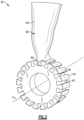
- the fan 42 includes a fan hub 43 that carries a plurality of fan blades or airfoils 60 (one shown for illustrative purposes) that are rotatable about the engine longitudinal axis A.
- the airfoil 60 includes a root section 62 and an airfoil section 64.
- the fan hub 43 defines a plurality of circumferentially spaced apart slots 45.
- the root section 62 of each airfoil 60 is dimensioned to be slideably received within a respective slot 45 to mount the airfoil 60 in the engine 10.
- the root section 62 has a generally dovetail geometry that mates with walls of the slot 45.
- FIGS 3-5 illustrate an example composite airfoil 160.
- like reference numerals designate like elements where appropriate and reference numerals with the addition of one-hundred or multiples thereof designate modified elements that are understood to incorporate the same features and benefits of the corresponding original elements.
- the airfoil 160 can be a fan blade incorporated into the fan 42 of Figures 1 and 2 , for example.
- Other portions of the engine can benefit from the teachings herein, such as fan exit guide vanes 41 or airfoils in the compressor or turbine sections 24, 28 of Figure 1 .
- Other systems can also benefit from the teachings disclosed herein, including ground-based power generation systems.
- the airfoil 160 includes a root section 162 and an airfoil section 164.
- the airfoil section 164 extends in a spanwise or radial direction R from the root section 162 to a tip 166.
- the tip 166 is a terminal end of the airfoil 160.
- the airfoil section 164 generally extends in a chordwise or axial direction X between a leading edge L/E and a trailing edge T/E.
- the airfoil section 164 defines a pressure side P and a suction side S separated in a thickness direction T.
- the airfoil section 164 provides an aerodynamic surface for guiding airflow to downstream portions of the engine in response to rotation of the airfoil 160.
- the root section 162 of the airfoil 160 is mounted to a rotor, such as the fan hub 43 of Figures 1 and 2 .
- span positions of the airfoil section 164 are schematically illustrated from 0% to 100% span in 10% increments to define a plurality of sections 167.
- Each section 167 at a given span position is provided by a conical cut that corresponds to the shape of segments of the bypass flowpath B or the core flow path C ( Figure 1 ), as shown by the large dashed lines.
- the 0% span position corresponds to the radially innermost location of the airfoil section 164 that meets the root section 162.
- a 100% span position corresponds to a section of the airfoil 160 at the tip 166.
- the airfoil 160 includes a composite core 168, a first skin 170 and a second skin 172.
- the core 168 defines the root section 162 and at least a portion of the airfoil section 164, with the core 168 terminating at an edge or boundary 174 (shown in dashed lines in Figure 3 ).
- the core 168 can extend along a mean camber line 171 (shown in dashed lines in Figure 4 ) that bisects a thickness of the airfoil 160 for at least some span positions of the airfoil section 164.
- the core 168 can be dimensioned to provide increased rigidity to localized portions of the root and airfoil sections 162, 164.
- the core 168 defines a portion of the airfoil section 164 such that the boundary 174 of the core 168 is spaced apart from the tip 166.
- the airfoil section 164 is free of the core 168 for at least a majority of span positions of the airfoil section 164.
- the boundary 174 of the core 168 terminates in the radial direction R along the airfoil section 164 prior to about 25% span, or more narrowly between about 5% span and about 20% span.
- the term "about” means ⁇ 3% of the respective quantity unless otherwise stated.
- the core 168 defines a portion of the tip 166, as illustrated by boundary 174' ( Figure 3 ).
- core 168' is skewed toward the leading edge L/E of the airfoil 160, as illustrated by boundary 174" of Figure 3 .
- a reference plane 175 is established along the airfoil section 164 between 0% and 100% span.
- the reference plane 175 is equidistant between the leading and trailing edges L/E, T/E for each respective span position.
- Core 168'' is situated such that a center of mass CM" of the core 168" is defined along the mean camber line 171 ( Figure 4 ) at a location between the leading edge L/E and the reference plane 175, whereas a center of mass CM of the core 168 may be situated along the reference plane 175, for example.
- situating the core 168" relatively closer to the leading edge L/E can provide improved localized impact resistance, while skins 170, 172 can provide relatively greater in-plane strength and stiffness to regions adjacent to the trailing edge T/E, for example. Terminating the core 168 prior to the tip 166 can provide the airfoil 160 with better in-plane strength and stiffness in regions where the core 168 is not present, but may have less delamination resistance.
- the skins 170, 172 extend along the core 168 to define external surfaces of the airfoil 160.
- the skins 170, 172 extend along opposed sides of the core 168 to define the root section 162.
- the root section 162 defines a dovetail geometry that interfaces with a respective slot 145 of a rotor (shown in dashed lines in Figure 5 ).
- the skins 170, 172 extend along the dovetail geometry to space apart the core 168 from walls of the respective slot 145.
- the skins 170, 172 can be relatively more compliant than the core 168, and can provide improved absorption of impacts and load transfer between the airfoil 160 and the fan hub 43 ( Figure 2 ) during engine operation, which can improve durability of the airfoil 160.
- the root section 162 is free of the skins 170, 172 such that the core 168 abuts the walls of the respective slot 145.
- the skins 170, 172 extend along opposed sides of the core 168 for at least some span positions of the airfoil section 164 and join together to define the tip 166.
- the boundary 174 of the core 168 can be contoured or tapered to provide a relatively smooth interface between the skins 170, 172.
- the skins 170, 172 are joined together along the leading and trailing edges L/E, T/E and define the pressure and suction sides P, S.
- the core 168 defines at least a portion of the leading and/or trailing edges L/E, T/E of the airfoil 160. In other examples, the core 168 is spaced apart from the leading and/or trailing edges L/E, T/E.
- the core 168 and skins 170, 172 can be made of various composite materials to define the airfoil 160.
- the core 168 and skins 170, 172 can be constructed from fibers arranged in various orientations and in one or more layers based on structural requirements.
- the core 168 and/or skins 170, 172 include carbon fibers.
- the core 168 and/or skins 170, 172 can be constructed from other materials, including fiberglass, an aramid such as Kevlar ® , a ceramic such as Nextel TM , and a polyethylene such as Spectra ® .
- the core 168 includes and is constructed from a three-dimensional network of fibers 176 ( Figure 7A ), which can be woven or interlaced.
- the three-dimensional network of fibers 176 can be formed from a dry fiber preform, for example.
- Each of the skins 170, 172 is a composite skin that includes and is constructed from a two-dimensional network of fibers 178 ( Figure 7B ), which can be woven or interlaced.
- the two-dimensional network of fibers 178 can be formed from a pre-impregnated ("prepreg") fabric or a pre-impregnated tape, for example.
- Pre-impregnating the fibers with resin can provide relatively greater strength and toughness to the composite article.
- Matrix (resin) materials used for prepreg can have greater toughness compared to matrix materials used with resin infusion methods, such that a part made from prepreg is relatively stronger, as measured by delamination resistance.
- the skins 170, 172 include a plurality of relatively thin uni-tape plies having a plurality of fibers oriented in the same direction.
- the core 168 and/or skins 170, 172 can include a network of biaxial braids 180 ( Figure 7C ).
- Other configurations for the core 168 and/or skins 170, 172 can include a network of tri-axial braids 182 ( Figure 7D ), for example.
- the skins 170, 172 include a network of stitched or non-crimped fabrics.
- the example fiber constructions are known in the art, but the incorporation of the fiber constructions into airfoil 160 to define the core 168 and skins 170, 172 utilizing the teachings herein are not known.
- the core 168 and/or skins 170, 172 can include different fiber types in the fiber directions to tailor the strength and stiffness of the core 168 and/or skins 170, 172.
- high modulus carbon fibers may be used in conjunction with low modulus carbon fibers.
- fiberglass or aramid fibers may be used in combination with carbon fibers.
- Incorporating a three-dimensional network of fibers into the core 168, including the three-dimensional network of woven or interlaced fibers 176 ( Figure 7A ), provides reinforcement in localized portions of the airfoil 160 that may be more susceptible to degradation due to impact from foreign objects.
- Incorporating a two-dimensional network of fibers into the skins 170, 172, including the two-dimensional network of fibers 178 ( Figure 7B ), can provide relatively greater in-plane strength and stiffness to other portions of the airfoil 160.
- FIG. 8 illustrates an example process in a flow chart 184 for forming a composite article or airfoil, such as airfoil 160.
- the techniques disclosed herein can improve structural properties of the airfoil 160, which can improve durability, and can reduce manufacturing cost.
- a core 168 is fabricated or otherwise prepared.
- the core 168 can be fabricated from a dry fiber preform to form or otherwise define a three-dimensional network of woven fibers.
- the core 168 may be fabricated on a loom using a weaving process, for example.
- a tackifier can be applied to the preform to prepare the core 168.
- the core 168 can be dimensioned according to expected stresses or impacts that may be observed during use of the composite article.
- first and second skins 170, 172 are fabricated or otherwise prepared.
- the skins 170, 172 can be prepared from a pre-impregnated fabric or pre-impregnated tape to form or otherwise define a two-dimensional network of fibers.
- the core 168 and skins 170, 172 can be arranged to establish a layup.
- the layup can be formed on a tool.
- Steps 186 and/or 188 can be performed by an automated fiber placement (AFP) process, or the steps can be performed manually by hand placement of a three-dimensional woven core and hand placing of prepreg plies to form the skins.
- AFP is generally known, and includes placement of narrow strips of unidirectional material or "tows" to build up the composite layers that constitute the article according to a predefined geometry.
- Forming the three-dimensional woven core 168 using the techniques disclosed herein can eliminate the need to form relatively small plies or layers that may otherwise be needed to fill a volume of the airfoil to define the airfoil geometry but that may not be practical to use in an AFP process.
- step 190 the skins 170, 172 are assembled or otherwise arranged relative to the core 168 in a mold.
- Surfaces of the mold can be dimensioned according to an external profile or contour of the airfoil 160.
- step 186 includes partially curing the core 168 at step 187 prior to step 190 and prior to positioning the core 168 in the mold, which may be referred to as a "b-staged" core.
- Step 187 can include infiltrating the core 168 with a resin that is chemically compatible with a resin used for subsequent injection. Once infiltration occurs, the core 168 is partially cured or "b-staged". As known, prepreg is already b-staged.
- Steps 186, 188 and/or 190 can be performed such that the airfoil section 164 is free of the core 168 for at least a majority of span positions of the airfoil section 164, including the core 168 terminating at any of the span positions disclosed herein.
- Step 192 a composite airfoil such as airfoil 160 is formed.
- Step 192 can include forming the core 168 and the skins 170, 172 together with resin in the mold to define the airfoil 160, and such that the core 168 defines the root section 162 of the airfoil 160 and the skins 170, 172 extend at least partially along the core 168 to define at least a portion of the root section 162 and the airfoil section 164 of the airfoil 160.
- Resin materials can include a thermoset epoxy, for example, and can infuse the dry fiber preform.
- step 192 can be performed using a closed-molding process.
- step 192 can be performed using a resin transfer molding (RTM) process or a resin pressure molding (RPM) process to define the airfoil 160 including forming the core 168 and skins 170, 172 together to define the root and airfoil sections 162, 164.
- RTM resin transfer molding
- RPM resin pressure molding
- Resin transfer molding is generally known for manufacturing composite articles.
- RTM is a closed-molding process that typically includes fabricating a fiber preform by laying up plies of fiber sheets in a stack, placing the fiber preform in a closed mold, and then saturating the fiber preform with a liquid thermoset resin.
- the resin is typically mixed with a catalyst or hardener prior to being injected into the closed mold, or can be previously mixed together in a one-part resin system.
- One-part resin systems already have the catalyst mixed with the resin.
- the article is heated in the mold to a desired temperature to cure the article.
- the mold can be heated using a liquid heating system, for example.
- the mold is heated by direct contact with heated platens such as in a compression press or free-standing in an oven.
- heated platens such as in a compression press or free-standing in an oven.
- VARTM vacuum-assisted resin transfer molding
- a vacuum is used to draw the resin into the mold.
- the RTM process generally results in a part with a slightly lower volume percentage of fiber compared to a part made from prepreg and processed in an autoclave.
- Resin pressure molding is generally known for manufacturing composite articles.
- RPM can be considered a variation of an RTM process.
- RPM is a closed-molding process which includes delivering a liquid resin into a closed mold in which some, or all, of the fiber reinforcement has been pre-impregnated with a resin. Thereafter and similar to RTM, a combination of elevated heat and hydrostatic resin pressure are applied to the mold to cure the article.
- Step 192 can include curing the core 168 and skins 170, 172 in the resin at step 198.
- Step 198 can occur subsequent to injecting or otherwise delivering the resin into the mold.
- Step 192 can include heating the mold to a predetermined temperature for a set period of time to at least partially or fully cure the core 168 and skins 170, 172.
- Step 192 can include applying resin pressure concurrently with heat to the core 168, skins 170, 172 and resin at step 196, such as during an RTM or RPM process.
- the RPM process can include utilization of a b-staged core 168 and prepreg skins 170, 172, or a dry fiber core 168 and prepreg skins 170, 172, for example.
- Forming the airfoil 160 with an RPM process can close any gaps in the composite article and can yield relatively better dimensional control of the cured article. This technique can eliminate separate injection and curing steps for the core 168.
- Pre-impregnated fabric or tape can provide the ability to use resin systems with a higher toughness and impact resistance as compared to resin that may be used in a transfer molding (RTM) process to infuse the dry fiber tape.
- the dry fiber preform used to form the core 168 is infused with resin, but the relatively lower toughness resin that may used in the RTM process is adequate since the three-dimensional network of fibers used to form the core 168 can provide relatively greater toughness and impact resistance.
- the skins 170, 172 including a two-dimensional network of fibers is formed from a dry fiber tape.
- a binder material can be added to the dry fiber tape to hold the layers of the fiber tape together and promote adhesion.
- finishing procedures can be performed on the cured composite article defining the airfoil 160 at step 194.
- Example finishing procedures can include one or more grinding operations to remove excess material at parting lines caused by the molding process, or final dimensioning of the airfoil 160 geometry.
- the core 168 is staged on a tool.
- the core 168 is integrated with the skins 170, 172.
- the core 168 and skins 170, 172 are then cured together in an autoclave.
Landscapes
- Engineering & Computer Science (AREA)
- Mechanical Engineering (AREA)
- General Engineering & Computer Science (AREA)
- Chemical & Material Sciences (AREA)
- Materials Engineering (AREA)
- Combustion & Propulsion (AREA)
- Textile Engineering (AREA)
- Composite Materials (AREA)
- Structures Of Non-Positive Displacement Pumps (AREA)
Claims (12)
- Schaufel (160) für ein Gasturbinentriebwerk (20), umfassend:einen Schaufelabschnitt (164), der sich in einer Sehnenrichtung zwischen einer Vorderkante (L/E) und einer Hinterkante (T/E) erstreckt und sich in einer Spannweitenrichtung (R) zwischen einer Spitze und einem Wurzelabschnitt (166, 162) erstreckt, wobei der Schaufelabschnitt (164) eine in einer Dickenrichtung (T) getrennte Saugseite (S) und Druckseite (P) definiert, wobei ein Verbundkern (168; 168") den Wurzelabschnitt (162) und einen Teil des Schaufelabschnitts (164) derart definiert, dass der Verbundkern (168; 168") von der Spitze (166) beabstandet ist, der Verbundkern (168; 168") ein dreidimensionales Netzwerk aus gewebten Fasern (176) beinhaltet, sich eine erste und zweite Haut (170, 172) an mindestens einigen Spannweitenpositionen des Schaufelabschnitts (164) entlang gegenüberliegender Seiten des Verbundkerns (168; 168") erstrecken und sich unter Definieren der Spitze (166) miteinander verbinden,dadurch gekennzeichnet, dass:
jede der ersten und zweiten Haut (170,172) eine Verbundhaut (170,172) ist, die ein zweidimensionales Fasernetzwerk (178) beinhaltet, die Fasern des zweidimensionalen Fasernetzwerks (178) gewebt oder verflochten sind, der Wurzelabschnitt (162) eine Schwalbenschwanzgeometrie definiert, die zum Einpassen in einen Schlitz (45) konfiguriert ist, und sich die erste und zweite Haut (170,172) entlang der Schwalbenschwanzgeometrie erstrecken und zum Beabstanden des Verbundkerns (168;168'') von den Wänden des Schlitzes (45) konfiguriert sind. - Schaufel (160) nach Anspruch 1, wobei der Schaufelabschnitt (164) an mindestens den meisten Spannweitenpositionen des Schaufelabschnitts (164) frei von dem Verbundkern (168; 168") ist, wobei der Verbundkern (168; 168") optional in der Spannweitenrichtung (R) entlang des Schaufelabschnitts (164) vor etwa 25 % der Spannweite endet.
- Schaufel (160) nach Anspruch 1 oder 2, wobei das dreidimensionale Netzwerk aus gewebten Fasern (176) aus einem Trockenfaservorformling ausgebildet ist.
- Schaufel (160) nach Anspruch 1, 2 oder 3, wobei der Verbundkern (168; 168") und die erste und zweite Haut (170, 172) gemeinsam durch Harzspritzpressen oder durch Harzdruckpressen unter Definieren des Schaufelabschnitts (164) und des Wurzelabschnitts (162) ausgebildet sind und/oder der Kern (168") in Richtung der Vorderkante (L/E) abgeschrägt ist.
- Verfahren zum Ausbilden einer Verbundschaufel (160) für ein Gasturbinentriebwerk (20), umfassend:Herstellen eines Kerns (168; 168"), der ein dreidimensionales Netzwerk aus gewebten Fasern (176) aufweist;Herstellen einer ersten und zweiten Haut (170, 172);Anordnen der ersten und zweiten Haut (170,172) relativ zu dem Kern (168;168") in einer Form; undAusbilden des Kerns (168; 168") und der ersten und zweiten Haut (170, 172) zusammen mit Harz in der Form unter Definieren einer Verbundschaufel (160) mit einem Schaufelabschnitt (164), der sich in einer Spannweitenrichtung (R) derart zwischen einer Spitze und einem Wurzelabschnitt (166, 162) erstreckt, dass der Kern (168; 168") den Wurzelabschnitt (162) und einen Teil des Schaufelabschnitts (164) derart definiert, dass der Verbundkern (168; 168") von der Spitze (166) beabstandet ist, und derart, dass sich die erste und zweite Haut (170, 172) unter Definieren des Schaufelabschnitts (164) der Verbundschaufel (160) mindestens teilweise entlang des Kerns (168; 168") erstrecken, und sich unter Definieren der Spitze (166) miteinander verbinden,dadurch gekennzeichnet, dass:
die erste und zweite Haut (170, 172) jeweils ein zweidimensionales Fasernetzwerk (178) aufweisen, die Fasern des zweidimensionalen Fasernetzwerks (178) gewebt oder verflochten sind, der Kern (168; 168") aus einem Trockenfaservorformling hergestellt ist, der Wurzelabschnitt (162) eine Schwalbenschwanzgeometrie definiert, die zum Einpassen in einen Schlitz (45) konfiguriert ist, und sich die erste und zweite Haut (170,172) entlang der Schwalbenschwanzgeometrie erstrecken und zum Beabstanden des Verbundkerns (168;168") von den Wänden des Schlitzes (45) konfiguriert sind. - Verfahren nach Anspruch 5, wobei der Schritt des Ausbildens Aushärten des Kerns (168; 168") und der ersten und zweiten Haut (170, 172) in dem Harz nach dem Einbringen des Harzes in die Form beinhaltet.
- Verfahren nach Anspruch 5 oder 6, wobei der Schritt des Ausbildens unter Verwendung eines Harzspritzpressprozesses durchgeführt wird, um den Schaufelabschnitt (164) und den Wurzelabschnitt (162) zu definieren.
- Verfahren nach Anspruch 5, 6 oder 7, wobei der Schritt des Herstellens der ersten und zweiten Haut (170, 172) durch einen automatisierten Faserplatzierungsprozess durchgeführt wird.
- Verfahren nach einem der Ansprüche 5 bis 8, ferner umfassend Teilaushärten des Kerns (168; 168'') vor dem Schritt des Anordnens.
- Verfahren nach einem der Ansprüche 5 bis 9, wobei das zweidimensionale Fasernetzwerk (178) aus einem Trockenfaserband ausgebildet wird.
- Verfahren oder Schaufel (160) nach einem der vorhergehenden Ansprüche, wobei das zweidimensionale Fasernetzwerk (178) aus einem vorimprägnierten Gewebe oder vorimprägnierten Band ausgebildet ist.
- Verfahren nach einem der Ansprüche 5 bis 11, wobei der Schritt des Anordnens derart durchgeführt wird, dass der Schaufelabschnitt (164) an mindesten den meisten Spannweitenpositionen des Schaufelabschnitts (164) frei von dem Kern (168; 168") ist.
Applications Claiming Priority (1)
| Application Number | Priority Date | Filing Date | Title |
|---|---|---|---|
| US15/966,109 US11346363B2 (en) | 2018-04-30 | 2018-04-30 | Composite airfoil for gas turbine |
Publications (2)
| Publication Number | Publication Date |
|---|---|
| EP3564487A1 EP3564487A1 (de) | 2019-11-06 |
| EP3564487B1 true EP3564487B1 (de) | 2025-04-16 |
Family
ID=66349407
Family Applications (1)
| Application Number | Title | Priority Date | Filing Date |
|---|---|---|---|
| EP19172045.7A Active EP3564487B1 (de) | 2018-04-30 | 2019-04-30 | Verbundschaufel für gasturbinenmotoren und entsprechendes herstellungsverfahren |
Country Status (2)
| Country | Link |
|---|---|
| US (1) | US11346363B2 (de) |
| EP (1) | EP3564487B1 (de) |
Families Citing this family (16)
| Publication number | Priority date | Publication date | Assignee | Title |
|---|---|---|---|---|
| US10034519B2 (en) | 2016-06-16 | 2018-07-31 | Adidas Ag | UV curable lattice microstructure for footwear |
| US11352897B2 (en) * | 2019-09-26 | 2022-06-07 | Raytheon Technologies Corporation | Double box composite seal assembly for gas turbine engine |
| US11359507B2 (en) * | 2019-09-26 | 2022-06-14 | Raytheon Technologies Corporation | Double box composite seal assembly with fiber density arrangement for gas turbine engine |
| FR3111658B1 (fr) | 2020-06-18 | 2022-07-15 | Safran Aircraft Engines | Aube en matériau composite à renfort fibreux tissé tridimensionnel et peau tissée bidimensionnel et son procédé de fabrication |
| FR3111660B1 (fr) * | 2020-06-18 | 2022-07-01 | Safran Aircraft Engines | Aube en matériau composite à peau tissée bidimensionnel intégrant un insert métallique et son procédé de fabrication |
| FR3134140B1 (fr) * | 2022-04-01 | 2024-08-30 | Safran | Renfort pour une aube composite d’une turbomachine, comprenant un mélange de découpes de fibre et d’un tackifiant |
| US12123321B2 (en) | 2022-12-27 | 2024-10-22 | General Electric Company | Composite airfoil assembly having a dovetail portion |
| US12241386B2 (en) * | 2023-02-21 | 2025-03-04 | General Electric Company | Turbine engine airfoil with a woven core and woven layer |
| US12241383B2 (en) * | 2023-02-24 | 2025-03-04 | General Electric Company | Turbine engine with a composite-airfoil assembly having a dovetail portion |
| US12286903B2 (en) | 2023-02-24 | 2025-04-29 | General Electric Company | Turbine engine including a composite airfoil assembly having a dovetail portion |
| US12078080B1 (en) * | 2023-04-21 | 2024-09-03 | General Electric Company | Airfoil assembly with a trunnion and spar |
| US12291974B2 (en) | 2023-05-17 | 2025-05-06 | General Electric Company | Turbine engine having an airfoil assembly with a trunnion and a spar |
| CN119686812B (zh) * | 2023-09-22 | 2025-11-25 | 中国航发商用航空发动机有限责任公司 | Cmc翼型件及其成型方法 |
| US12535008B2 (en) * | 2023-10-03 | 2026-01-27 | General Electric Company | Airfoil assembly having a composite core |
| US12359570B2 (en) * | 2023-10-27 | 2025-07-15 | General Electric Company | Composite airfoil assembly for a turbine engine |
| EP4603379A1 (de) * | 2024-02-14 | 2025-08-20 | General Electric Company | Verbundschaufelanordnung mit einer verbundschaufel und holm |
Family Cites Families (48)
| Publication number | Priority date | Publication date | Assignee | Title |
|---|---|---|---|---|
| US4480957A (en) | 1983-04-14 | 1984-11-06 | General Electric Company | Dynamic response modification and stress reduction in dovetail and blade assembly |
| GB2168111B (en) | 1984-12-08 | 1988-05-18 | Rolls Royce | Rotor aerofoil blade containment |
| US5129787A (en) | 1991-02-13 | 1992-07-14 | United Technologies Corporation | Lightweight propulsor blade with internal spars and rigid base members |
| US5123813A (en) * | 1991-03-01 | 1992-06-23 | General Electric Company | Apparatus for preloading an airfoil blade in a gas turbine engine |
| US5340280A (en) | 1991-09-30 | 1994-08-23 | General Electric Company | Dovetail attachment for composite blade and method for making |
| US5279892A (en) | 1992-06-26 | 1994-01-18 | General Electric Company | Composite airfoil with woven insert |
| US5310317A (en) | 1992-08-11 | 1994-05-10 | General Electric Company | Quadra-tang dovetail blade |
| US5443367A (en) | 1994-02-22 | 1995-08-22 | United Technologies Corporation | Hollow fan blade dovetail |
| US5431542A (en) | 1994-04-29 | 1995-07-11 | United Technologies Corporation | Ramped dovetail rails for rotor blade assembly |
| US5573377A (en) | 1995-04-21 | 1996-11-12 | General Electric Company | Assembly of a composite blade root and a rotor |
| JPH1054204A (ja) | 1996-05-20 | 1998-02-24 | General Electric Co <Ge> | ガスタービン用の多構成部翼 |
| US5725355A (en) | 1996-12-10 | 1998-03-10 | General Electric Company | Adhesive bonded fan blade |
| US5839882A (en) | 1997-04-25 | 1998-11-24 | General Electric Company | Gas turbine blade having areas of different densities |
| US6039542A (en) | 1997-12-24 | 2000-03-21 | General Electric Company | Panel damped hybrid blade |
| US6231941B1 (en) | 1998-07-14 | 2001-05-15 | The Boeing Company | Radius fillers for a resin transfer molding process |
| GB2345943B (en) | 1998-12-04 | 2003-07-09 | Glenn Bruce Sinclair | Precision crowning of blade attachments in gas turbines |
| US6290466B1 (en) | 1999-09-17 | 2001-09-18 | General Electric Company | Composite blade root attachment |
| US7121803B2 (en) | 2002-12-26 | 2006-10-17 | General Electric Company | Compressor blade with dovetail slotted to reduce stress on the airfoil leading edge |
| US6902376B2 (en) | 2002-12-26 | 2005-06-07 | General Electric Company | Compressor blade with dovetail slotted to reduce stress on the airfoil leading edge |
| US7329101B2 (en) | 2004-12-29 | 2008-02-12 | General Electric Company | Ceramic composite with integrated compliance/wear layer |
| US7435058B2 (en) | 2005-01-18 | 2008-10-14 | Siemens Power Generation, Inc. | Ceramic matrix composite vane with chordwise stiffener |
| US7458780B2 (en) | 2005-08-15 | 2008-12-02 | United Technologies Corporation | Hollow fan blade for gas turbine engine |
| FR2890126B1 (fr) | 2005-08-26 | 2010-10-29 | Snecma | Ensemble et procede pour le montage du pied d'une aube de turbomachine, soufflante, compresseur et turbomachine comportant un tel ensemble |
| US7451639B2 (en) | 2006-03-07 | 2008-11-18 | Jentek Sensors, Inc. | Engine blade dovetail inspection |
| DE102006049818A1 (de) | 2006-10-18 | 2008-04-24 | Rolls-Royce Deutschland Ltd & Co Kg | Fanschaufel aus Textilverbundwerkstoff |
| US7828526B2 (en) | 2007-04-11 | 2010-11-09 | General Electric Company | Metallic blade having a composite inlay |
| FR2918702B1 (fr) | 2007-07-13 | 2009-10-16 | Snecma Sa | Clinquant pour aube de turbomachine |
| US8241003B2 (en) | 2008-01-23 | 2012-08-14 | United Technologies Corp. | Systems and methods involving localized stiffening of blades |
| US8585368B2 (en) | 2009-04-16 | 2013-11-19 | United Technologies Corporation | Hybrid structure airfoil |
| US9488059B2 (en) | 2009-08-05 | 2016-11-08 | Hamilton Sundstrand Corporation | Fan blade dovetail with compliant layer |
| US20110129348A1 (en) | 2009-11-30 | 2011-06-02 | United Technologies Corporation | Core driven ply shape composite fan blade and method of making |
| FR2954271B1 (fr) * | 2009-12-21 | 2012-02-17 | Snecma | Pale d'helice d'aeronef |
| US20110176927A1 (en) | 2010-01-20 | 2011-07-21 | United Technologies Corporation | Composite fan blade |
| US20110211965A1 (en) | 2010-02-26 | 2011-09-01 | United Technologies Corporation | Hollow fan blade |
| US8573947B2 (en) | 2010-03-10 | 2013-11-05 | United Technologies Corporation | Composite fan blade dovetail root |
| FR2962175B1 (fr) * | 2010-07-02 | 2012-08-10 | Snecma | Aube a longeron composite integre |
| US9556742B2 (en) | 2010-11-29 | 2017-01-31 | United Technologies Corporation | Composite airfoil and turbine engine |
| US20130064676A1 (en) | 2011-09-13 | 2013-03-14 | United Technologies Corporation | Composite filled metal airfoil |
| FR2984848B1 (fr) * | 2011-12-23 | 2016-01-15 | Ratier Figeac Soc | Pale d'helice avec caissons et longerons de renfort et helice comprenant au moins une telle pale |
| US9221120B2 (en) | 2012-01-04 | 2015-12-29 | United Technologies Corporation | Aluminum fan blade construction with welded cover |
| US9457435B2 (en) | 2012-01-25 | 2016-10-04 | Snecma | Method for producing a propeller blade from a composite material |
| US9845688B2 (en) | 2013-03-15 | 2017-12-19 | Rolls-Royce Corporation | Composite blade with an integral blade tip shroud and method of forming the same |
| WO2015004362A1 (fr) * | 2013-07-08 | 2015-01-15 | Snecma | Pale d'hélice composite pour aéronef |
| WO2015034630A1 (en) | 2013-09-09 | 2015-03-12 | United Technologies Corporation | Airfoil with an integrally stiffened composite cover |
| US20160032939A1 (en) | 2014-07-31 | 2016-02-04 | General Electric Company | Airfoil structures |
| US10099434B2 (en) | 2014-09-16 | 2018-10-16 | General Electric Company | Composite airfoil structures |
| GB201417769D0 (en) | 2014-10-08 | 2014-11-19 | Rolls Royce Plc | Composite article |
| US10590945B2 (en) | 2016-08-10 | 2020-03-17 | United Technologies Corporation | Fiber composite material and preform and fan blade made therefrom |
-
2018
- 2018-04-30 US US15/966,109 patent/US11346363B2/en active Active
-
2019
- 2019-04-30 EP EP19172045.7A patent/EP3564487B1/de active Active
Also Published As
| Publication number | Publication date |
|---|---|
| EP3564487A1 (de) | 2019-11-06 |
| US11346363B2 (en) | 2022-05-31 |
| US20190331127A1 (en) | 2019-10-31 |
Similar Documents
| Publication | Publication Date | Title |
|---|---|---|
| EP3564487B1 (de) | Verbundschaufel für gasturbinenmotoren und entsprechendes herstellungsverfahren | |
| EP3044415B1 (de) | Schaufel mit einer integral versteiften verbundumhüllung | |
| EP2971549B1 (de) | Laufschaufel eines gasturbinentriebwerks, zugehöriges gasturbinentriebwerk und herstellungsverfahren | |
| EP3587736B1 (de) | Composite-gasturbinenschaufel mit sich teilenden fasern in der plattform | |
| US9777593B2 (en) | Hybrid metal and composite spool for rotating machinery | |
| US12173725B2 (en) | Blade comprising a structure made of composite material and associated manufacturing method | |
| US12264597B2 (en) | Monolithic composite blade and platform | |
| WO2014200571A2 (en) | Composite attachment structure with 3d weave | |
| US12435647B1 (en) | Composite casing for a turbine engine | |
| US11391167B2 (en) | Hybrid airfoil for gas turbine engines | |
| US12338747B2 (en) | Turbine engine with composite airfoils | |
| US20250215801A1 (en) | Reinforcement for a composite blade of a turbomachine, comprising a mixture of fiber cuts and a tackifier | |
| US20250215800A1 (en) | Reinforcement for a composite blade of a turbomachine, comprising a stack of plies | |
| US12359572B2 (en) | Turbine engine with composite airfoils | |
| US12618177B2 (en) | Method of manufacturing a woven fabric for a composite component for a turbine engine | |
| EP4653591A1 (de) | Dreidimensionales gewebe für ein verbundbauteil | |
| EP4653590A1 (de) | Verfahren zur herstellung eines gewebes für eine verbundkomponente für einen turbinenmotor | |
| EP4737689A1 (de) | Turbinenmotorrahmenanordnung mit einer montageklammeranordnung | |
| US20260124811A1 (en) | Method of manufacturing a composite component for a gas turbine engine | |
| CN121989469A (zh) | 用于涡轮发动机的复合翼型件的预制件 | |
| EP4737088A1 (de) | Verfahren zur herstellung einer verbundkomponente für einen gasturbinenmotor | |
| CN121993295A (zh) | 具有安装支架组件的涡轮发动机框架组件 |
Legal Events
| Date | Code | Title | Description |
|---|---|---|---|
| PUAI | Public reference made under article 153(3) epc to a published international application that has entered the european phase |
Free format text: ORIGINAL CODE: 0009012 |
|
| STAA | Information on the status of an ep patent application or granted ep patent |
Free format text: STATUS: THE APPLICATION HAS BEEN PUBLISHED |
|
| AK | Designated contracting states |
Kind code of ref document: A1 Designated state(s): AL AT BE BG CH CY CZ DE DK EE ES FI FR GB GR HR HU IE IS IT LI LT LU LV MC MK MT NL NO PL PT RO RS SE SI SK SM TR |
|
| AX | Request for extension of the european patent |
Extension state: BA ME |
|
| STAA | Information on the status of an ep patent application or granted ep patent |
Free format text: STATUS: REQUEST FOR EXAMINATION WAS MADE |
|
| 17P | Request for examination filed |
Effective date: 20200522 |
|
| RBV | Designated contracting states (corrected) |
Designated state(s): AL AT BE BG CH CY CZ DE DK EE ES FI FR GB GR HR HU IE IS IT LI LT LU LV MC MK MT NL NO PL PT RO RS SE SI SK SM TR |
|
| STAA | Information on the status of an ep patent application or granted ep patent |
Free format text: STATUS: EXAMINATION IS IN PROGRESS |
|
| 17Q | First examination report despatched |
Effective date: 20200821 |
|
| RAP1 | Party data changed (applicant data changed or rights of an application transferred) |
Owner name: RAYTHEON TECHNOLOGIES CORPORATION |
|
| RAP3 | Party data changed (applicant data changed or rights of an application transferred) |
Owner name: RTX CORPORATION |
|
| GRAP | Despatch of communication of intention to grant a patent |
Free format text: ORIGINAL CODE: EPIDOSNIGR1 |
|
| STAA | Information on the status of an ep patent application or granted ep patent |
Free format text: STATUS: GRANT OF PATENT IS INTENDED |
|
| INTG | Intention to grant announced |
Effective date: 20240529 |
|
| GRAJ | Information related to disapproval of communication of intention to grant by the applicant or resumption of examination proceedings by the epo deleted |
Free format text: ORIGINAL CODE: EPIDOSDIGR1 |
|
| STAA | Information on the status of an ep patent application or granted ep patent |
Free format text: STATUS: EXAMINATION IS IN PROGRESS |
|
| INTC | Intention to grant announced (deleted) | ||
| GRAP | Despatch of communication of intention to grant a patent |
Free format text: ORIGINAL CODE: EPIDOSNIGR1 |
|
| STAA | Information on the status of an ep patent application or granted ep patent |
Free format text: STATUS: GRANT OF PATENT IS INTENDED |
|
| INTG | Intention to grant announced |
Effective date: 20241108 |
|
| GRAS | Grant fee paid |
Free format text: ORIGINAL CODE: EPIDOSNIGR3 |
|
| GRAA | (expected) grant |
Free format text: ORIGINAL CODE: 0009210 |
|
| STAA | Information on the status of an ep patent application or granted ep patent |
Free format text: STATUS: THE PATENT HAS BEEN GRANTED |
|
| AK | Designated contracting states |
Kind code of ref document: B1 Designated state(s): AL AT BE BG CH CY CZ DE DK EE ES FI FR GB GR HR HU IE IS IT LI LT LU LV MC MK MT NL NO PL PT RO RS SE SI SK SM TR |
|
| REG | Reference to a national code |
Ref country code: GB Ref legal event code: FG4D |
|
| REG | Reference to a national code |
Ref country code: CH Ref legal event code: EP Ref country code: DE Ref legal event code: R096 Ref document number: 602019068612 Country of ref document: DE |
|
| REG | Reference to a national code |
Ref country code: IE Ref legal event code: FG4D |
|
| PGFP | Annual fee paid to national office [announced via postgrant information from national office to epo] |
Ref country code: DE Payment date: 20250423 Year of fee payment: 7 |
|
| REG | Reference to a national code |
Ref country code: NL Ref legal event code: MP Effective date: 20250416 |
|
| PG25 | Lapsed in a contracting state [announced via postgrant information from national office to epo] |
Ref country code: NL Free format text: LAPSE BECAUSE OF FAILURE TO SUBMIT A TRANSLATION OF THE DESCRIPTION OR TO PAY THE FEE WITHIN THE PRESCRIBED TIME-LIMIT Effective date: 20250416 |
|
| REG | Reference to a national code |
Ref country code: AT Ref legal event code: MK05 Ref document number: 1785819 Country of ref document: AT Kind code of ref document: T Effective date: 20250416 |
|
| PG25 | Lapsed in a contracting state [announced via postgrant information from national office to epo] |
Ref country code: FI Free format text: LAPSE BECAUSE OF FAILURE TO SUBMIT A TRANSLATION OF THE DESCRIPTION OR TO PAY THE FEE WITHIN THE PRESCRIBED TIME-LIMIT Effective date: 20250416 Ref country code: ES Free format text: LAPSE BECAUSE OF FAILURE TO SUBMIT A TRANSLATION OF THE DESCRIPTION OR TO PAY THE FEE WITHIN THE PRESCRIBED TIME-LIMIT Effective date: 20250416 Ref country code: PT Free format text: LAPSE BECAUSE OF FAILURE TO SUBMIT A TRANSLATION OF THE DESCRIPTION OR TO PAY THE FEE WITHIN THE PRESCRIBED TIME-LIMIT Effective date: 20250818 |
|
| REG | Reference to a national code |
Ref country code: LT Ref legal event code: MG9D |
|
| PG25 | Lapsed in a contracting state [announced via postgrant information from national office to epo] |
Ref country code: NO Free format text: LAPSE BECAUSE OF FAILURE TO SUBMIT A TRANSLATION OF THE DESCRIPTION OR TO PAY THE FEE WITHIN THE PRESCRIBED TIME-LIMIT Effective date: 20250716 Ref country code: GR Free format text: LAPSE BECAUSE OF FAILURE TO SUBMIT A TRANSLATION OF THE DESCRIPTION OR TO PAY THE FEE WITHIN THE PRESCRIBED TIME-LIMIT Effective date: 20250717 |
|
| PG25 | Lapsed in a contracting state [announced via postgrant information from national office to epo] |
Ref country code: PL Free format text: LAPSE BECAUSE OF FAILURE TO SUBMIT A TRANSLATION OF THE DESCRIPTION OR TO PAY THE FEE WITHIN THE PRESCRIBED TIME-LIMIT Effective date: 20250416 |
|
| PG25 | Lapsed in a contracting state [announced via postgrant information from national office to epo] |
Ref country code: BG Free format text: LAPSE BECAUSE OF FAILURE TO SUBMIT A TRANSLATION OF THE DESCRIPTION OR TO PAY THE FEE WITHIN THE PRESCRIBED TIME-LIMIT Effective date: 20250416 |
|
| PG25 | Lapsed in a contracting state [announced via postgrant information from national office to epo] |
Ref country code: HR Free format text: LAPSE BECAUSE OF FAILURE TO SUBMIT A TRANSLATION OF THE DESCRIPTION OR TO PAY THE FEE WITHIN THE PRESCRIBED TIME-LIMIT Effective date: 20250416 |
|
| PG25 | Lapsed in a contracting state [announced via postgrant information from national office to epo] |
Ref country code: AT Free format text: LAPSE BECAUSE OF FAILURE TO SUBMIT A TRANSLATION OF THE DESCRIPTION OR TO PAY THE FEE WITHIN THE PRESCRIBED TIME-LIMIT Effective date: 20250416 |
|
| PG25 | Lapsed in a contracting state [announced via postgrant information from national office to epo] |
Ref country code: RS Free format text: LAPSE BECAUSE OF FAILURE TO SUBMIT A TRANSLATION OF THE DESCRIPTION OR TO PAY THE FEE WITHIN THE PRESCRIBED TIME-LIMIT Effective date: 20250716 |
|
| PG25 | Lapsed in a contracting state [announced via postgrant information from national office to epo] |
Ref country code: IS Free format text: LAPSE BECAUSE OF FAILURE TO SUBMIT A TRANSLATION OF THE DESCRIPTION OR TO PAY THE FEE WITHIN THE PRESCRIBED TIME-LIMIT Effective date: 20250816 |
|
| PG25 | Lapsed in a contracting state [announced via postgrant information from national office to epo] |
Ref country code: LV Free format text: LAPSE BECAUSE OF FAILURE TO SUBMIT A TRANSLATION OF THE DESCRIPTION OR TO PAY THE FEE WITHIN THE PRESCRIBED TIME-LIMIT Effective date: 20250416 |
|
| REG | Reference to a national code |
Ref country code: CH Ref legal event code: H13 Free format text: ST27 STATUS EVENT CODE: U-0-0-H10-H13 (AS PROVIDED BY THE NATIONAL OFFICE) Effective date: 20251125 |
|
| PG25 | Lapsed in a contracting state [announced via postgrant information from national office to epo] |
Ref country code: LU Free format text: LAPSE BECAUSE OF NON-PAYMENT OF DUE FEES Effective date: 20250430 |
|
| REG | Reference to a national code |
Ref country code: BE Ref legal event code: MM Effective date: 20250430 |
|
| PG25 | Lapsed in a contracting state [announced via postgrant information from national office to epo] |
Ref country code: SM Free format text: LAPSE BECAUSE OF FAILURE TO SUBMIT A TRANSLATION OF THE DESCRIPTION OR TO PAY THE FEE WITHIN THE PRESCRIBED TIME-LIMIT Effective date: 20250416 Ref country code: DK Free format text: LAPSE BECAUSE OF FAILURE TO SUBMIT A TRANSLATION OF THE DESCRIPTION OR TO PAY THE FEE WITHIN THE PRESCRIBED TIME-LIMIT Effective date: 20250416 |
|
| PG25 | Lapsed in a contracting state [announced via postgrant information from national office to epo] |
Ref country code: BE Free format text: LAPSE BECAUSE OF NON-PAYMENT OF DUE FEES Effective date: 20250430 |
|
| PG25 | Lapsed in a contracting state [announced via postgrant information from national office to epo] |
Ref country code: CH Free format text: LAPSE BECAUSE OF NON-PAYMENT OF DUE FEES Effective date: 20250430 |
|
| REG | Reference to a national code |
Ref country code: DE Ref legal event code: R097 Ref document number: 602019068612 Country of ref document: DE |
|
| PG25 | Lapsed in a contracting state [announced via postgrant information from national office to epo] |
Ref country code: CZ Free format text: LAPSE BECAUSE OF FAILURE TO SUBMIT A TRANSLATION OF THE DESCRIPTION OR TO PAY THE FEE WITHIN THE PRESCRIBED TIME-LIMIT Effective date: 20250416 |
|
| PG25 | Lapsed in a contracting state [announced via postgrant information from national office to epo] |
Ref country code: EE Free format text: LAPSE BECAUSE OF FAILURE TO SUBMIT A TRANSLATION OF THE DESCRIPTION OR TO PAY THE FEE WITHIN THE PRESCRIBED TIME-LIMIT Effective date: 20250416 |
|
| PG25 | Lapsed in a contracting state [announced via postgrant information from national office to epo] |
Ref country code: SK Free format text: LAPSE BECAUSE OF FAILURE TO SUBMIT A TRANSLATION OF THE DESCRIPTION OR TO PAY THE FEE WITHIN THE PRESCRIBED TIME-LIMIT Effective date: 20250416 Ref country code: RO Free format text: LAPSE BECAUSE OF FAILURE TO SUBMIT A TRANSLATION OF THE DESCRIPTION OR TO PAY THE FEE WITHIN THE PRESCRIBED TIME-LIMIT Effective date: 20250416 |
|
| PG25 | Lapsed in a contracting state [announced via postgrant information from national office to epo] |
Ref country code: IT Free format text: LAPSE BECAUSE OF FAILURE TO SUBMIT A TRANSLATION OF THE DESCRIPTION OR TO PAY THE FEE WITHIN THE PRESCRIBED TIME-LIMIT Effective date: 20250416 |
|
| PG25 | Lapsed in a contracting state [announced via postgrant information from national office to epo] |
Ref country code: MC Free format text: LAPSE BECAUSE OF FAILURE TO SUBMIT A TRANSLATION OF THE DESCRIPTION OR TO PAY THE FEE WITHIN THE PRESCRIBED TIME-LIMIT Effective date: 20250416 |
|
| PLBE | No opposition filed within time limit |
Free format text: ORIGINAL CODE: 0009261 |
|
| STAA | Information on the status of an ep patent application or granted ep patent |
Free format text: STATUS: NO OPPOSITION FILED WITHIN TIME LIMIT |
|
| REG | Reference to a national code |
Ref country code: CH Ref legal event code: L10 Free format text: ST27 STATUS EVENT CODE: U-0-0-L10-L00 (AS PROVIDED BY THE NATIONAL OFFICE) Effective date: 20260225 |
|
| 26N | No opposition filed |
Effective date: 20260119 |
|
| PGFP | Annual fee paid to national office [announced via postgrant information from national office to epo] |
Ref country code: GB Payment date: 20260319 Year of fee payment: 8 |
|
| PG25 | Lapsed in a contracting state [announced via postgrant information from national office to epo] |
Ref country code: IE Free format text: LAPSE BECAUSE OF NON-PAYMENT OF DUE FEES Effective date: 20250430 |
|
| PGFP | Annual fee paid to national office [announced via postgrant information from national office to epo] |
Ref country code: FR Payment date: 20260320 Year of fee payment: 8 |