EP3564111B1 - Electric assistance system and electrically assisted vehicle - Google Patents
Electric assistance system and electrically assisted vehicle Download PDFInfo
- Publication number
- EP3564111B1 EP3564111B1 EP17888447.4A EP17888447A EP3564111B1 EP 3564111 B1 EP3564111 B1 EP 3564111B1 EP 17888447 A EP17888447 A EP 17888447A EP 3564111 B1 EP3564111 B1 EP 3564111B1
- Authority
- EP
- European Patent Office
- Prior art keywords
- electric
- acceleration
- motor
- assist
- torque
- Prior art date
- Legal status (The legal status is an assumption and is not a legal conclusion. Google has not performed a legal analysis and makes no representation as to the accuracy of the status listed.)
- Active
Links
Images





Classifications
-
- B—PERFORMING OPERATIONS; TRANSPORTING
- B60—VEHICLES IN GENERAL
- B60L—PROPULSION OF ELECTRICALLY-PROPELLED VEHICLES; SUPPLYING ELECTRIC POWER FOR AUXILIARY EQUIPMENT OF ELECTRICALLY-PROPELLED VEHICLES; ELECTRODYNAMIC BRAKE SYSTEMS FOR VEHICLES IN GENERAL; MAGNETIC SUSPENSION OR LEVITATION FOR VEHICLES; MONITORING OPERATING VARIABLES OF ELECTRICALLY-PROPELLED VEHICLES; ELECTRIC SAFETY DEVICES FOR ELECTRICALLY-PROPELLED VEHICLES
- B60L15/00—Methods, circuits, or devices for controlling the traction-motor speed of electrically-propelled vehicles
- B60L15/20—Methods, circuits, or devices for controlling the traction-motor speed of electrically-propelled vehicles for control of the vehicle or its driving motor to achieve a desired performance, e.g. speed, torque, programmed variation of speed
- B60L15/2045—Methods, circuits, or devices for controlling the traction-motor speed of electrically-propelled vehicles for control of the vehicle or its driving motor to achieve a desired performance, e.g. speed, torque, programmed variation of speed for optimising the use of energy
-
- B—PERFORMING OPERATIONS; TRANSPORTING
- B60—VEHICLES IN GENERAL
- B60L—PROPULSION OF ELECTRICALLY-PROPELLED VEHICLES; SUPPLYING ELECTRIC POWER FOR AUXILIARY EQUIPMENT OF ELECTRICALLY-PROPELLED VEHICLES; ELECTRODYNAMIC BRAKE SYSTEMS FOR VEHICLES IN GENERAL; MAGNETIC SUSPENSION OR LEVITATION FOR VEHICLES; MONITORING OPERATING VARIABLES OF ELECTRICALLY-PROPELLED VEHICLES; ELECTRIC SAFETY DEVICES FOR ELECTRICALLY-PROPELLED VEHICLES
- B60L15/00—Methods, circuits, or devices for controlling the traction-motor speed of electrically-propelled vehicles
- B60L15/20—Methods, circuits, or devices for controlling the traction-motor speed of electrically-propelled vehicles for control of the vehicle or its driving motor to achieve a desired performance, e.g. speed, torque, programmed variation of speed
- B60L15/2054—Methods, circuits, or devices for controlling the traction-motor speed of electrically-propelled vehicles for control of the vehicle or its driving motor to achieve a desired performance, e.g. speed, torque, programmed variation of speed by controlling transmissions or clutches
-
- B—PERFORMING OPERATIONS; TRANSPORTING
- B60—VEHICLES IN GENERAL
- B60L—PROPULSION OF ELECTRICALLY-PROPELLED VEHICLES; SUPPLYING ELECTRIC POWER FOR AUXILIARY EQUIPMENT OF ELECTRICALLY-PROPELLED VEHICLES; ELECTRODYNAMIC BRAKE SYSTEMS FOR VEHICLES IN GENERAL; MAGNETIC SUSPENSION OR LEVITATION FOR VEHICLES; MONITORING OPERATING VARIABLES OF ELECTRICALLY-PROPELLED VEHICLES; ELECTRIC SAFETY DEVICES FOR ELECTRICALLY-PROPELLED VEHICLES
- B60L15/00—Methods, circuits, or devices for controlling the traction-motor speed of electrically-propelled vehicles
- B60L15/20—Methods, circuits, or devices for controlling the traction-motor speed of electrically-propelled vehicles for control of the vehicle or its driving motor to achieve a desired performance, e.g. speed, torque, programmed variation of speed
- B60L15/2036—Electric differentials, e.g. for supporting steering vehicles
-
- B—PERFORMING OPERATIONS; TRANSPORTING
- B60—VEHICLES IN GENERAL
- B60L—PROPULSION OF ELECTRICALLY-PROPELLED VEHICLES; SUPPLYING ELECTRIC POWER FOR AUXILIARY EQUIPMENT OF ELECTRICALLY-PROPELLED VEHICLES; ELECTRODYNAMIC BRAKE SYSTEMS FOR VEHICLES IN GENERAL; MAGNETIC SUSPENSION OR LEVITATION FOR VEHICLES; MONITORING OPERATING VARIABLES OF ELECTRICALLY-PROPELLED VEHICLES; ELECTRIC SAFETY DEVICES FOR ELECTRICALLY-PROPELLED VEHICLES
- B60L50/00—Electric propulsion with power supplied within the vehicle
- B60L50/20—Electric propulsion with power supplied within the vehicle using propulsion power generated by humans or animals
-
- B—PERFORMING OPERATIONS; TRANSPORTING
- B62—LAND VEHICLES FOR TRAVELLING OTHERWISE THAN ON RAILS
- B62M—RIDER PROPULSION OF WHEELED VEHICLES OR SLEDGES; POWERED PROPULSION OF SLEDGES OR SINGLE-TRACK CYCLES; TRANSMISSIONS SPECIALLY ADAPTED FOR SUCH VEHICLES
- B62M6/00—Rider propulsion of wheeled vehicles with additional source of power, e.g. combustion engine or electric motor
- B62M6/40—Rider propelled cycles with auxiliary electric motor
- B62M6/45—Control or actuating devices therefor
-
- B—PERFORMING OPERATIONS; TRANSPORTING
- B60—VEHICLES IN GENERAL
- B60L—PROPULSION OF ELECTRICALLY-PROPELLED VEHICLES; SUPPLYING ELECTRIC POWER FOR AUXILIARY EQUIPMENT OF ELECTRICALLY-PROPELLED VEHICLES; ELECTRODYNAMIC BRAKE SYSTEMS FOR VEHICLES IN GENERAL; MAGNETIC SUSPENSION OR LEVITATION FOR VEHICLES; MONITORING OPERATING VARIABLES OF ELECTRICALLY-PROPELLED VEHICLES; ELECTRIC SAFETY DEVICES FOR ELECTRICALLY-PROPELLED VEHICLES
- B60L2200/00—Type of vehicles
- B60L2200/12—Bikes
-
- B—PERFORMING OPERATIONS; TRANSPORTING
- B60—VEHICLES IN GENERAL
- B60L—PROPULSION OF ELECTRICALLY-PROPELLED VEHICLES; SUPPLYING ELECTRIC POWER FOR AUXILIARY EQUIPMENT OF ELECTRICALLY-PROPELLED VEHICLES; ELECTRODYNAMIC BRAKE SYSTEMS FOR VEHICLES IN GENERAL; MAGNETIC SUSPENSION OR LEVITATION FOR VEHICLES; MONITORING OPERATING VARIABLES OF ELECTRICALLY-PROPELLED VEHICLES; ELECTRIC SAFETY DEVICES FOR ELECTRICALLY-PROPELLED VEHICLES
- B60L2240/00—Control parameters of input or output; Target parameters
- B60L2240/10—Vehicle control parameters
- B60L2240/14—Acceleration
- B60L2240/16—Acceleration longitudinal
-
- B—PERFORMING OPERATIONS; TRANSPORTING
- B60—VEHICLES IN GENERAL
- B60L—PROPULSION OF ELECTRICALLY-PROPELLED VEHICLES; SUPPLYING ELECTRIC POWER FOR AUXILIARY EQUIPMENT OF ELECTRICALLY-PROPELLED VEHICLES; ELECTRODYNAMIC BRAKE SYSTEMS FOR VEHICLES IN GENERAL; MAGNETIC SUSPENSION OR LEVITATION FOR VEHICLES; MONITORING OPERATING VARIABLES OF ELECTRICALLY-PROPELLED VEHICLES; ELECTRIC SAFETY DEVICES FOR ELECTRICALLY-PROPELLED VEHICLES
- B60L2240/00—Control parameters of input or output; Target parameters
- B60L2240/40—Drive Train control parameters
- B60L2240/42—Drive Train control parameters related to electric machines
- B60L2240/421—Speed
-
- B—PERFORMING OPERATIONS; TRANSPORTING
- B60—VEHICLES IN GENERAL
- B60L—PROPULSION OF ELECTRICALLY-PROPELLED VEHICLES; SUPPLYING ELECTRIC POWER FOR AUXILIARY EQUIPMENT OF ELECTRICALLY-PROPELLED VEHICLES; ELECTRODYNAMIC BRAKE SYSTEMS FOR VEHICLES IN GENERAL; MAGNETIC SUSPENSION OR LEVITATION FOR VEHICLES; MONITORING OPERATING VARIABLES OF ELECTRICALLY-PROPELLED VEHICLES; ELECTRIC SAFETY DEVICES FOR ELECTRICALLY-PROPELLED VEHICLES
- B60L2240/00—Control parameters of input or output; Target parameters
- B60L2240/40—Drive Train control parameters
- B60L2240/42—Drive Train control parameters related to electric machines
- B60L2240/423—Torque
-
- Y—GENERAL TAGGING OF NEW TECHNOLOGICAL DEVELOPMENTS; GENERAL TAGGING OF CROSS-SECTIONAL TECHNOLOGIES SPANNING OVER SEVERAL SECTIONS OF THE IPC; TECHNICAL SUBJECTS COVERED BY FORMER USPC CROSS-REFERENCE ART COLLECTIONS [XRACs] AND DIGESTS
- Y02—TECHNOLOGIES OR APPLICATIONS FOR MITIGATION OR ADAPTATION AGAINST CLIMATE CHANGE
- Y02T—CLIMATE CHANGE MITIGATION TECHNOLOGIES RELATED TO TRANSPORTATION
- Y02T10/00—Road transport of goods or passengers
- Y02T10/60—Other road transportation technologies with climate change mitigation effect
- Y02T10/64—Electric machine technologies in electromobility
-
- Y—GENERAL TAGGING OF NEW TECHNOLOGICAL DEVELOPMENTS; GENERAL TAGGING OF CROSS-SECTIONAL TECHNOLOGIES SPANNING OVER SEVERAL SECTIONS OF THE IPC; TECHNICAL SUBJECTS COVERED BY FORMER USPC CROSS-REFERENCE ART COLLECTIONS [XRACs] AND DIGESTS
- Y02—TECHNOLOGIES OR APPLICATIONS FOR MITIGATION OR ADAPTATION AGAINST CLIMATE CHANGE
- Y02T—CLIMATE CHANGE MITIGATION TECHNOLOGIES RELATED TO TRANSPORTATION
- Y02T10/00—Road transport of goods or passengers
- Y02T10/60—Other road transportation technologies with climate change mitigation effect
- Y02T10/72—Electric energy management in electromobility
Definitions
- the present invention relates to an electric assist system usable for an electric assist vehicle, and an electric assist vehicle including the electric assist system.
- Prior art document EP 2 711 285 A1 discloses an electric bicycle and a control method thereof.
- the control method of the electric bicycle in which a motor is rotated using electric energy stored in a battery to drive the electric bicycle, includes receiving an acceleration instruction value to accelerate the electric bicycle, input by a driver, during traveling, calculating a reference value according to a traveling velocity of the electric bicycle, and increasing time taken for a rotating velocity of the motor to reach a target velocity, if the received acceleration instruction value is more than the calculated reference value.
- an electronic control unit receives an acceleration instruction value input by the driver according to the pedal torque sensed by a pedal torque sensing unit.
- Prior art document EP 0 926 059 A2 discloses an electric assist system usable for an electric assist vehicle including a pedal, corresponding to the preamble of claim 1.
- the electric assist system comprises a crankshaft rotatable by human power of a rider applied to the pedal and a torque sensor outputting a torque signal in accordance with a magnitude of a torque generated at the crankshaft.
- An electric motor is used to generate assist power assisting the human power of the rider.
- An acceleration detection unit is provided for outputting an acceleration signal in accordance with a current acceleration in a travel direction of the electric assist vehicle.
- a control device receives the torque signal and the acceleration signal and determines a magnitude of the assist power to be generated by the electric motor.
- the control device calculates a acceleration in the reference environment from the torque signal based on a rule prepared in advance, and determines the magnitude of the assist power to be generated by the electric motor.
- control device 70 a specific structure of the control device 70, and a group of sensors that generate a signal usable to operate the control device 70, will be described in detail.
- the X axis, the Y axis and the Z axis of the electric assist bicycle 1 running on a flat road may not match the X axis, the Y axis and the Z axis of the electric assist bicycle 1 running on a slope.
- the operation panel 60 includes a display panel 61, an assist mode operation switch 62, and a power source switch 65.
- the speed display area 61a displays the vehicle speed of the electric assist bicycle 1 by numerical figures.
- the vehicle speed of the electric assist bicycle 1 is detected by a speed sensor 35 provided on the front wheel 25.
- the power source switch 65 is a switch by which the power source of the electric assist bicycle 1 is switched on or off. The rider presses the power source switch 65 to switch the power source of the electric assist bicycle 1 on or off.
- the speaker 63 may be caused to generate an audio signal of a volume that is heard by people around the electric assist bicycle 1, or the head lamp 22 and the tail lamp 23 may be lit up or blinked. With such an arrangement, the people around the electric assist bicycle 1 recognize that the electric assist bicycle 1 is generating assist power larger than the usual assist power.
- the electric motor 53 In the case where the assist mode is "standard", the electric motor 53 generates assist power when, for example, the electric assist bicycle 1 is to start, is running on a flat road, or is running on an ascending slope. In the case where the assist mode is "high”, the electric motor 53 generates assist power when, for example, the electric assist bicycle 1 is to start, is running on a flat road, or is running on an ascending slope, like in the case where the assist mode is "standard”. In the case where the assist mode is "high”, the electric motor 53 generates larger assist power than in the case where the assist mode is "standard” in response to the same crank rotation output.
- the assist power in response to the crank rotation output is varied in accordance with the assist mode described above.
- the assist mode is switched to any one of four stages.
- the assist mode may be switched to any of three stages or less, or any of five stages or more.
- the magnitude of the human power (pedal force) of the rider applied to the pedal 55 is increased or decreased in accordance with the position of the pedal 55, namely, the rotation angle of the crankshaft 57.
- the increase or the decrease in the pedal force applied to the pedal 55 appears as increase or decrease in the torque generated at the crankshaft 57.
- the motive power that runs the electric assist bicycle 1 is increased or decreased. Therefore, the acceleration in the travel direction x of the electric assist bicycle 1 is increased or decreased in accordance with the increase or the decrease in the torque.
- FIG. 4 shows a state where a right pedal 55R of the electric assist bicycle 1, on which the rider puts his/her right foot, is located just above the crankshaft 57, whereas a left pedal 55L of the electric assist bicycle 1, on which the rider puts his/her left foot, is located just below the crankshaft 57.
- the rotation angle of the crankshaft 57 at this point is set as 0 degrees.
- the torque generated at the crankshaft 57 by the human power is minimum.
- the acceleration in the travel direction x is also minimum.
- FIG. 4 shows a state where the left pedal 55L is located to the front, in the horizontal direction, of the crankshaft 57, whereas the right pedal 55R is located to the rear, in the horizontal direction, of the crankshaft 57.
- the rotation angle of the crankshaft 57 at this point is set as 270 degrees.
- the torque generated at the crankshaft 57 by the human power is maximum.
- the acceleration in the travel direction x of the vehicle is also maximum.
- a peak of the ridge represents the maximum value of the torque in the zone.
- a bottom of the trough of the torque represents the minimum value of the torque in the zone.
- the zone between the ridge and the trough adjacent to each other includes the peak of the ridge and the bottom of the trough.
- the rider While the rider is pedaling the electric assist bicycle 1 on a flat road in the certain pedaling manner, the rider is considered to wish to run the electric assist bicycle 1 at an acceleration changing periodically as shown in FIG. 4 .
- the electric assist bicycle 1 is influenced by various external disturbances. For this reason, the acceleration changing periodically as shown in FIG. 4 may not be obtained.
- a headwind caused by the running of the electric assist bicycle 1, a wind meteorologically generated and/or a slope are all examples of the external disturbances.
- the present inventor conceived adjusting the assist power of the electric assist bicycle 1 such that while the rider is pedaling the electric assist bicycle 1 in the certain pedaling manner, the rider runs the electric assist bicycle 1 with the sense of acceleration changing periodically as shown in FIG. 4 regardless of whether there is any external disturbance or not.
- the "sense of acceleration” used in this specification refers to the sense of speed that the rider feels by increase or decrease in the speed in the travel direction while running the electric assist bicycle 1 with the acceleration changing periodically as shown in FIG. 4 .
- the "sense of acceleration” is different from the acceleration detected by the acceleration sensor 38. As described below, on a slope, the acceleration sensor 38 detects an acceleration in accordance with the inclination.
- FIG. 5A schematically shows a waveform of a value of the torque obtained based on the torque signal.
- the control device 70 calculates a target acceleration from the torque signal, and determines the magnitude of the assist power to be generated by the electric motor 53 such that the deviation between the target acceleration and the current acceleration is decreased.
- the value of the torque represented by the torque signal is a value directly indicating with what acceleration the rider wishes to drive the electric assist bicycle 1, and set a map or a function defining the correspondence between the torque signal and the target acceleration.
- the map or function may be used to determine the target acceleration uniquely from the value of the torque.
- FIG. 5A schematically shows a waveform of the target acceleration calculated based on the torque.
- the target acceleration is smaller; whereas as the value of the torque is larger, the target acceleration is larger.
- the value of the target acceleration may be increased or decreased in synchronization with the value of the torque.
- FIG. 5A schematically shows the acceleration in the travel direction x of the vehicle.
- the solid line represents a waveform of the acceleration signal that is output from the acceleration sensor 38
- the dashed line represents the waveform of the target acceleration.
- P-P(t) a difference between the ridge and the trough, adjacent to each other, of the acceleration at time t.
- the difference P-P(t) and a difference P-P(t+1) will be compared against each other.
- the acceleration value of the latter has a larger amplitude in the negative direction. Therefore, the deviation En(t+1) between the acceleration value and the target acceleration value at time (t+1) is relatively large.
- control device 70 determines the magnitude of the assist power to be generated by the electric motor 53 such that the deviation En(t+1) is decreased.
- the term "decreased” refers to, for example, "made 0 (zero)".
- the control device 70 After the electric assist bicycle 1 is subjected to the headwind, the control device 70 generates larger assist power. As a result, at time (t+2) , a deviation En(t+2) is converged to approximately 0. This indicates that the rider is subjected to the headwind but maintains the same acceleration as long as keeping on pedaling the electric assist bicycle 1 with the same pedal force (torque).
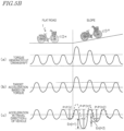
- FIG. 5B shows an example of motion of the electric assist bicycle 1 in the case where the rider receives, from a slope, a downward force parallel to the inclining surface as a load. It is assumed that the electric assist bicycle 1 runs on a flat road up to a certain time point and then, starts running on a slope at the timing represented by the dotted line parallel to the up-down direction of the figure.
- (b) and (c) of FIG. 5B respectively show the target acceleration and the current acceleration. In each of (b) and (c) of FIG.
- the waveform after the electric assist bicycle 1 starts running on the slope is provided as a waveform obtained as a result of removing, by a high-pass filter, a low-frequency component of the acceleration which is added in accordance with the slope. This process will be described below in detail.
- FIG. 5B schematically shows a waveform of a value of the torque obtained based on the torque signal.
- the rider rides the electric assist bicycle 1 in the certain pedaling manner on a flat road, but pedals the electric assist bicycle 1 with a larger pedal force immediately after the start of the slope.
- Such a manner of pedaling is common.
- a reason for this is that before and after the start of the slope, the rider expects that the speed will be decreased due to the ascending slope, and intuitively pedals the electric assist bicycle 1 strongly.
- (b) of FIG. 5B schematically shows a waveform of the target acceleration calculated based on the torque.
- the target acceleration is smaller; whereas as the value of the torque is larger, the target acceleration is larger. It is understood that in synchronization with the larger pedal force immediately after the start of the slope, the target acceleration is calculated to be larger than that before the start of the slope.
- FIG. 5B schematically shows the acceleration in the travel direction x of the vehicle.
- the solid line represents a waveform of the acceleration signal that is output from the acceleration sensor 38, and the dashed line represents the waveform of the target acceleration.
- the difference P-P(t) and the difference P-P(t+1) will be compared against each other.
- the acceleration value of the latter has a larger amplitude in the negative direction. Therefore, the deviation En(t+1) between the acceleration value and the target acceleration value at time (t+1) is relatively large.
- the control device 70 determines the magnitude of the assist power to be generated by the electric motor 53 such that the deviation En(t+1) is decreased.
- the term "decreased” refers to, for example, "made 0 (zero)".
- control device 70 will be described with reference to FIG. 2A again, and then, an operation performed by the control device 70 will be described.
- the averaging circuit 78 is a digital filtering circuit that smooths a detection signal regarding each of the axial directions that is output from the acceleration sensor 38.
- the averaging circuit 78 may, for example, calculate a moving average of a plurality of detection signals to smooth the detection signals. Another smoothing algorithm may be used.
- the averaging circuit 78 is provided. Nonetheless, according to the present invention, it is not indispensable to provide the averaging circuit 78.
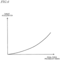
- the target acceleration calculation block 72 receives a torque signal from the torque sensor 41, and refers to an acceleration calculation rule 77a stored in advance on the storage block 77 described below to calculate the target acceleration from the torque signal.
- the correspondence between torque signal and the target acceleration is represented as a nonlinear continuous function. This is an example.
- the correspondence between torque signal and the target acceleration may be represented as a linear continuous function, or may be represented by a map or a table that associates the signal value of the torque signal and the target acceleration in a one-to-one manner.
- FIG. 6 may be extended.
- a different function, map or table may be selected in accordance with the selected assist mode.
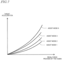
- FIG. 7 shows the relationship between the pedal force provided by the human (torque signal) and the target acceleration that is defined for each of the N pieces of selectable assist modes. It is assumed that the assist ratio is lowest in assist mode 1 and is highest in assist mode N. In the example shown in FIG. 7 , as the assist mode is of a higher assist ratio, a larger target acceleration may be set for the same pedal force.
- the motor electric current command value calculation block 74 calculates the motor electric current command value, based on which subsequent processes are to be performed.
- the magnitude of the torque to be generated by the electric motor 53 is in proportion to the level of the electric current to flow in the electric motor 53. Once the level of the electric current that is to flow in the electric motor 53 is determined, the magnitude of the torque to be generated is determined uniquely. Namely, determining the motor electric current command value is determining the magnitude of the torque to be generated by the electric motor 53.
- the transmission gear range sensor 48 detects the transmission gear range of the transmission included in the power transmission mechanism 31.
- the magnitude of the assist power to be applied to the ground by the rear wheel 26 changes in accordance with the level of the transmission gear range. Therefore, the output value of the transmission gear range sensor 48 is also considered to be one of the basic parameters usable to calculate the motor electric current command value.
- the motor electric current command value calculation block 74 further receives speed data from the speed sensor 35.
- the motor electric current command value calculation block 74 finds the motor electric current command value such that, for example, the torque to be generated at the driving shaft of the rear wheel 26 by the pedal force and the torque to be generated at the driving shaft of the rear wheel 26 by the driving motor 53 are equal to each other (assist ratio is 1:1).
- the motor electric current command value may be found by use of, for example, a predefined "table representing the relationship between the human power torque and the motor electric current command value". In this process, the motor electric current command value calculation block 74 calculates the motor electric current command value further in consideration of the deceleration ratio of the decelerator that decelerates the rotation of the electric motor 53.
- the motor electric current command value correction block 75 receives the motor electric current command value calculated by the motor electric current command value calculation block 74, the value of the target acceleration that is output from the target acceleration calculation block 72, and the value of the acceleration sensor 38 (value of the detected acceleration) that is output from the high-pass filter 73.
- the motor electric current command value correction block 75 corrects the motor electric current command value such that the detected acceleration matches the target acceleration.
- the motor electric current command value correction block 75 determines the motor torque Fm, corresponding to the assist power to be generated, by the electric motor 53 by the following expression.
- Fm t Kp ⁇ e t + Ki ⁇ ⁇ 0 l e ⁇ d ⁇ + Kd ⁇ de t dt .
- the second term of the right side represents a calculation regarding the integration element (integration control calculation).
- proportion control calculation the amount of operation is decreased as the current value is made closer to the target value. Therefore, the deviation remains.
- the integration control calculation is used to further decrease such a residual deviation.
- the residual deviation is temporally accumulated. When the residual deviation reaches a certain magnitude, the amount of operation may be increased to further decrease the residual deviation.
- the motor electric current command value correction block 75 determines the torque of a magnitude in proportion to the accumulated value of the residual deviation.
- the motor electric current command value correction block 76 corrects the motor electric current command value in accordance with the vehicle speed.
- a predetermined value or higher e.g. 10 km per hour or higher
- the upper limit of the assist ratio is gradually decreased.
- the assist ratio is 1:0, namely, the assist output is zero.
- the motor electric current command value correction block 76 determines the ratio of such gradual decrease by use of, for example, a predefined "table representing the relationship between the vehicle speed and the ratio of gradual decrease".
- the motor electric current command value is multiplied by the ratio of gradual decrease, so that the torque to be generated by the electric motor 53 is gradually decreased.
- the change in the ratio of gradual decrease may be linear or curved.
- the motor electric current command value correction block 76 also corrects the motor electric current command value in accordance with the rotation speed of the crankshaft 57. While, for example, the electric assist bicycle 1 is running at a low speed immediately before stopping, the feel of driving varies in accordance with when the generation of the assist power is stopped. For example, there is a case where the feel of driving is improved by generating slight assist power continuously even though the pedal force is substantially zero. In such a case, the rotation speed of the crankshaft 57 may be referred to, so that it is checked whether or not the rider intends to drive. While the crankshaft 57 is moving, namely, the rider is pedaling, the assist power is generated; and when the crankshaft 57 is stopped, the generation of the assist power is stopped. In this manner, the feel of driving is improved.
- the motor electric current command value correction block 76 outputs the motor electric current command value to the motor driving circuit 79.
- the motor driving circuit 79 supplies the electric motor 53 with an electric current of a level in accordance with the motor electric current command value.
- the motor electric current command value received by the motor driving circuit 79 represents the level of the electric current to be actually caused to flow in the electric motor 53.
- the motor electric current command value is considered to represent the target motor electric current value.
- the motor driving circuit 79 monitors and controls the amount of the electric current such that the electric current of the level indicated by the target motor electric current value flows. It is preferred that the control performed in this process is feedback control. In this embodiment, the motor driving circuit 79 performs PID control as the feedback control.
- the PID control is a well-known control method represented by expression 1 shown above. Thus, the details of the process will not be described.
- the motor driving circuit 79 may use any control method as long as the level of the electric current actually flowing may be controlled to match the motor electric current command value.
- the driving unit 51 includes an electric current sensor 47 in order to monitor the electric current.
- the electric current sensor 47 detects a value of the electric current flowing in the electric motor 53 and outputs the value to the motor driving circuit 79.
- the motor driving circuit 79 uses the output signal of the electric current sensor 47 to perform the feedback control.
- the electric currents of sine waveforms that are shifted by 120 degrees with respect to each other flow.
- the "value of the electric current” generally refers to the amplitude of the waveform, and may be represented as the difference P-P (Peak to Peak) between the maximum value and the minimum value of the electric current.
- a method for calculating the difference P-P from an actual measurement value of the electric current is well-known.
- the motor driving circuit 79 may substitute two actual measurement values of the electric currents, detected by the electric current sensor 47, into a predetermined calculation expression to find the difference P-P.
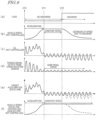
- the vertical axis represents the magnitude of the load received by the electric assist bicycle 1 and the rider thereof.
- the vertical axis represents the vehicle speed in the travel direction of the vehicle.
- FIG. 9(b) shows the vehicle speed in the case where the process according to this embodiment is not performed.
- the vertical axis represents the acceleration signal Gx in the x-axis direction that is output from the acceleration sensor 38.
- FIG. 9(c) shows a waveform of the vehicle acceleration signal Gx in the x-axis direction in the case where the control according to this embodiment is not performed.
- FIG. 10 shows waveforms of various signals when a load change occurs while the rider is pedaling the electric assist bicycle 1.
- the load change is assumed to be caused when the flat road is changed to a slope.
- the situation shown in FIG. 10 corresponds to FIG. 5B referred to above.
- FIG. 10(c) shows a waveform of the vehicle acceleration signal Gx in the x-axis direction in the case where the control according to this embodiment is not performed.
- the vertical axis represents the acceleration signal having a low-frequency component removed by the high-pass filter 73.
- the vertical axis represents the torque signal that is output from the crank rotation sensor 42 in the case where the process according to this embodiment is not performed.
- the vertical axis represents the torque signal that is output from the crank rotation sensor 42 in the case where the process according to this embodiment is performed.
- the vertical axis represents the target acceleration (solid line) found from the torque signal shown in FIG. 10(f) . It should be noted that this target acceleration does not include a signal component that is caused by the slope and is added to the output of the acceleration sensor 38.
- the vertical axis represents the vehicle speed (solid line) in the case where the control according to this embodiment is performed.
- FIG. 10(h) also shows, with the dashed line, a waveform of the vehicle speed in the x-axis direction in the case where the control according to this embodiment is not performed.
- FIG. 11A will be referred to.
- the electric assist bicycle 1 is the point mass that is present at the position of the gravitational center thereof, the gravitational force M.G is applied to the electric assist bicycle 1 in a vertically downward direction.
- the acceleration sensor 38 is constantly influenced by the gravitational force. Therefore, in the state where the electric assist bicycle 1 is still, the acceleration sensor 38 detects the gravitational acceleration G acting in the vertically downward direction (e.g., negative direction of the Z-axis direction).
- the situation is the same in FIG. 11B .
- the electric assist bicycle 1 In the state of being still on a slope, the electric assist bicycle 1 is still against a component, of the gravitational force, in a direction going down the slope (against M ⁇ G ⁇ sin ⁇ 0 ) . Where the direction going down the slope is negative, the acceleration in this state is -G ⁇ sin ⁇ 0 .
- the electric assist bicycle 1 still on the slope is accelerating at a magnitude of G ⁇ sin ⁇ 0 in a direction going up the slope so as to counteract the acceleration in the direction going down the slope (so as to counteract G ⁇ sin ⁇ 0 ). Namely, the acceleration is +G ⁇ sin ⁇ 0 .
- the acceleration +G ⁇ sin ⁇ 0 is constantly overlapped.
- FIG. 12 shows the acceleration signal as a target for the case where the low-frequency component is not removed by the high-pass filter 73 (solid line).
- FIG. 12 also shows the acceleration signal in the case where the process according to this embodiment is not performed (dashed line).
- the acceleration signal having the low-frequency component removed by the high-pass filter 73 is used.
- the result is the same even in the case where the target acceleration value is set as represented by the solid line in FIG. 12 .
- the use of the high-pass filter 73 realizes the same process as that in the case where the headwind or the like occurs, regardless of whether the electric assist bicycle 1 is running on a slope or not.
- an illustrative electric assist system (driving unit 51) according to the present invention is usable for an electric assist vehicle (electric assist bicycle 1) including the pedal 55.
- the electric assist system includes the crankshaft 57 rotatable by human power of a rider applied to the pedal; the torque sensor 41 outputting a torque signal in accordance with a magnitude of a torque generated at the crankshaft; the electric motor 53 generating assist power assisting the human power of the rider; the acceleration sensor 38 outputting an acceleration signal in accordance with a current acceleration in a travel direction of the electric assist vehicle; and the control device 70 receiving the torque signal and the acceleration signal and determining a magnitude of the assist power to be generated by the electric motor.
- the control device calculates a target acceleration from the torque signal based on a rule prepared in advance, and determines the magnitude of the assist power to be generated by the electric motor such that a deviation between the target acceleration and the current acceleration is decreased.
- the magnitude of the human power of the rider applied to the pedal changes in accordance with the position of the pedal while the rider is rotating the pedal. Therefore, the acceleration in the travel direction of the electric assist bicycle changes in accordance with the position of the pedal while the rider is rotating the pedal.
- the electric assist system changes the magnitude of the assist power to be generated by the electric motor such that the deviation between the target acceleration found from the pedal force of the rider and the current acceleration of the vehicle is decreased. Even if a load is applied during the running, the pedal force of the rider is considered to represent the sense of acceleration desired by the rider. Therefore, the target acceleration is set based on the pedal force, and the current acceleration of the vehicle is controlled to be made closer to the target acceleration. With such an arrangement, the rider may run the electric assist vehicle with an appropriate magnitude of assist power in accordance with the load during the running.
- control device 70 may determine the magnitude of the assist power to be generated by the electric motor 53 such that the deviation is made closer to 0.
- the ability of making the acceleration closer to the target acceleration may be improved.
- control device 70 includes the storage device 77 holding the rule prepared in advance.
- control device 70 includes the high-pass filter 73 transmitting a high-frequency component of a predefined frequency or higher that is included in the received acceleration signal.
- control device 70 includes the high-pass filter 73 transmitting a high-frequency component of 5 Hz or higher.
- the torque signal changes in accordance with the rotation of the crankshaft that is associated with an operation of the rider rotating the pedal
- the acceleration signal changes in accordance with the operation of the rider rotating the pedal and an external disturbance applied to the electric assist vehicle (electric assist bicycle 1)
- the control device 70 calculates the target acceleration from the torque signal, calculates the acceleration from the acceleration signal, and determines the magnitude of the assist power to be generated by the electric motor 53.
- the electric assist system (driving unit 51) further includes the motor driving circuit 79 outputting, to the electric motor, an electric current having at least one of an amplitude, a frequency and a flow direction controlled in accordance with a command value.
- the control device 70 outputs, to the motor driving circuit 79, a command value usable to cause an electric current that is in accordance with the determined magnitude of the assist power to flow.
- an appropriate magnitude of assist power may be generated such that the target acceleration in accordance with the pedal force during the running is obtained.
- An electric assist vehicle (electric assist bicycle 1) according to an illustrative embodiment of the present invention includes the above-described electric assist system (driving unit 51).
- the electric assist vehicle includes the front wheel 25 and the rear wheel 26; and the power transmission mechanism 31 transmitting the human power of the rider and the assist power to the rear wheel.
- the electric assist vehicle including the electric assist system according to an illustrative embodiment of the present invention may generate appropriate magnitude of assist power such that the target acceleration in accordance with the pedal force during the running is obtained.
- the present invention is especially useful for a vehicle that includes an acceleration sensor and is driven by human power assisted by assist power.
Landscapes
- Engineering & Computer Science (AREA)
- Transportation (AREA)
- Mechanical Engineering (AREA)
- Power Engineering (AREA)
- Chemical & Material Sciences (AREA)
- Combustion & Propulsion (AREA)
- Electric Propulsion And Braking For Vehicles (AREA)
Description
- The present invention relates to an electric assist system usable for an electric assist vehicle, and an electric assist vehicle including the electric assist system.
- Prior
art document EP 2 711 285 A1 discloses an electric bicycle and a control method thereof. The control method of the electric bicycle in which a motor is rotated using electric energy stored in a battery to drive the electric bicycle, includes receiving an acceleration instruction value to accelerate the electric bicycle, input by a driver, during traveling, calculating a reference value according to a traveling velocity of the electric bicycle, and increasing time taken for a rotating velocity of the motor to reach a target velocity, if the received acceleration instruction value is more than the calculated reference value. In particular, an electronic control unit receives an acceleration instruction value input by the driver according to the pedal torque sensed by a pedal torque sensing unit. - Prior
art document EP 0 926 059 A2 discloses an electric assist system usable for an electric assist vehicle including a pedal, corresponding to the preamble ofclaim 1. - The electric assist system comprises a crankshaft rotatable by human power of a rider applied to the pedal and a torque sensor outputting a torque signal in accordance with a magnitude of a torque generated at the crankshaft. An electric motor is used to generate assist power assisting the human power of the rider. An acceleration detection unit is provided for outputting an acceleration signal in accordance with a current acceleration in a travel direction of the electric assist vehicle. A control device receives the torque signal and the acceleration signal and determines a magnitude of the assist power to be generated by the electric motor. The control device calculates a acceleration in the reference environment from the torque signal based on a rule prepared in advance, and determines the magnitude of the assist power to be generated by the electric motor. In particular, the human drive force detected by a human drive power detection unit pulsates in response to the rotation of the pedal crank. The period of the pulsation is inversely proportional to the rotation speed of the pedal crank. For this reason, when the pulsating human drive force is used, the assist ratio is changed frequently, whereby the ride comfort of the vehicle may be lowered. To solve this problem, it may be possible to have a configuration wherein the human drive power detection unit calculates the average value of a plurality of continuously detected human drive force values, and outputs the average value to the acceleration calculation unit and the assist ratio determination unit.
- An electric assist bicycle, by which power of a rider pedaling the bicycle is assisted by an electric motor, is known. In such an electric assist bicycle, assist power in accordance with human power applied by the rider to a pedal is generated by the electric motor, and a motive power as a sum of the human power and the assist power is transmitted to a driving wheel. The human power may be assisted by the electric motor, so that the burden on the rider is alleviated (e.g., Patent Document No. 1).
- Patent Document No. 1:
Japanese Laid-Open Patent Publication No. 09-226664 - The rider pedals an electric assist bicycle, and as a result, the electric assist bicycle is accelerated, runs at a constant speed, or is decelerated.
- In the case where the human power applied to the pedal of the electric assist bicycle is kept the same, as the load on the vehicle is increased, the change ratio (acceleration) of the vehicle speed is decreased. For example, in the case where the human power applied to the pedal is kept the same, the change ratio (acceleration) of the vehicle speed is lower while the vehicle is running on a slope than while the vehicle is running on a flat road. The rider may feel inconvenient that the change ratio (acceleration) of the vehicle speed changes despite that the rider keeps on rotating the pedal with the same force.
- It is the object of the present invention to provide an electric assist system generating an appropriate magnitude of assist power in accordance with a load while an electric assist vehicle is running, and an electric assist vehicle including the electric assist system. According to the present invention said object is solved by an electric assist system according to the
independent claim 1. Preferred embodiments are laid down in the dependent claims. - An electric assist system according to the present invention is an electric assist system usable for an electric assist vehicle including a pedal. The electric assist system includes a crankshaft rotatable by human power of a rider applied to the pedal; a torque sensor outputting a torque signal in accordance with a magnitude of a torque generated at the crankshaft; an electric motor generating assist power assisting the human power of the rider; an acceleration sensor outputting an acceleration signal in accordance with a current acceleration in a travel direction of the electric assist vehicle; and a control device receiving the torque signal and the acceleration signal and determining a magnitude of the assist power to be generated by the electric motor. The control device calculates a target acceleration from the torque signal based on a rule prepared in advance, and determines the magnitude of the assist power to be generated by the electric motor such that a deviation between the target acceleration and the current acceleration is decreased.
- Because of the structure of the bicycle of allowing the rider to have his/her foot step on, and rotate, the pedal, the magnitude of the human power of the rider applied to the pedal changes in accordance with the position of the pedal while the rider is rotating the pedal. Therefore, the acceleration in the travel direction of the electric assist bicycle changes in accordance with the position of the pedal while the rider is rotating the pedal. The electric assist system changes the magnitude of the assist power to be generated by the electric motor such that the deviation between the target acceleration found from the pedal force of the rider and the current acceleration of the vehicle is decreased. Even if a load is applied during the running, the pedal force of the rider is considered to represent the sense of acceleration desired by the rider. Therefore, the target acceleration is set based on the pedal force, and the current acceleration of the vehicle is controlled to made closer to the target acceleration. With such an arrangement, the rider may run the electric assist vehicle with an appropriate magnitude of assist power in accordance with the load during the running.
- In an embodiment, the control device performs PID control to determine the magnitude of the assist power to be generated by the electric motor and thus to decrease the deviation.
- In an embodiment, where a current deviation at current time t is represented as E(t), and feedback gains of a proportional element, a differential element and an integration element of the assist power control system are respectively represented as Kp, Kd and Ki, the control device may determine a motor torque Fm, corresponding to the assist power to be generated by the electric motor, by the following expression:

- In an embodiment, the control device may determine the magnitude of the assist power to be generated by the electric motor such that the deviation is made closer to 0.
- In any of the above-described embodiments, the ability of making the acceleration closer to the target acceleration may be improved.
- In an embodiment, the control device stores, in advance, a table associating a command value for an electric current that is to flow in the electric motor and a magnitude of a motor torque corresponding to the assist power to be generated by the electric motor to each other, and refers to the table to determine the command value for the electric current required to generate the motor torque.
- In an embodiment, the control device stores, in advance, a table associating a command value for an electric current that is to flow in the electric motor and a magnitude of a motor torque to each other for each of ranges of magnitudes of the deviation, and refers to the table to determine the command value for the electric current required to generate the motor torque.
- In an embodiment, where a current deviation at current time t is represented as E(t), and feedback gains usable to find a command value for an electric current from a proportion term, an integration term and a differential term regarding a residual deviation are respectively represented as Kp', Kd' and Ki', the control device determines the command value Im, for the electric current that is to flow in the electric motor, by the following expression:

- In an embodiment, the control device includes a storage device holding the rule prepared in advance.
- In an embodiment, the rule may be a map or a function defining the correspondence between the torque signal and the target acceleration.
- In an embodiment, the function may be a nonlinear function or a linear function.
- In an embodiment, the control device includes a high-pass filter transmitting a high-frequency component of a predefined frequency or higher that is included in the received acceleration signal.
- In an embodiment, the control device includes a high-pass filter transmitting a high-frequency component of 5 Hz or higher.
- The high-pass filter may be provided, so that the acceleration generated by the rider rotating the pedal is appropriately extracted.
- According to the present invention, during a time period in which the rider rotates the pedal to make one rotation of the crankshaft, the torque sensor and the acceleration sensor respectively output a torque signal and an acceleration signal continuously, and the control device determines the magnitude of the assist power to be generated by the electric motor temporally continuously.
- In an embodiment, during a time period in which the rider rotates the pedal to make one rotation of the crankshaft, the torque signal changes in accordance with the rotation of the crankshaft that is associated with an operation of the rider rotating the pedal, the acceleration signal changes in accordance with the operation of the rider rotating the pedal and an external disturbance applied to the electric assist vehicle, and the control device calculates the target acceleration from the torque signal, calculates the acceleration from the acceleration signal, and determines the magnitude of the assist power to be generated by the electric motor at a predefined timing.
- In an embodiment, the electric assist system further includes a motor driving circuit outputting, to the electric motor, an electric current having at least one of an amplitude, a frequency and a flow direction controlled in accordance with a command value. The control device outputs, to the motor driving circuit, a command value usable to cause an electric current that is in accordance with the determined magnitude of the assist power to flow. With such an arrangement, an appropriate magnitude of assist power may be generated such that the target acceleration in accordance with the pedal force during the running is obtained.
- An electric assist vehicle according to an illustrative embodiment of the present invention includes the above-described electric assist system. In an embodiment, the electric assist vehicle includes a front wheel and a rear wheel; and a power transmission mechanism transmitting the human power of the rider and the assist power to the rear wheel. The electric assist vehicle including the electric assist system according to an illustrative embodiment of the present invention may generate an appropriate magnitude of assist power such that the target acceleration in accordance with the pedal force during the running is obtained.
- According to an illustrative embodiment of the present invention, the magnitude of the assist power to be generated by the electric motor is changed such that the deviation between the target acceleration found from the pedal force of the rider and the current acceleration is decreased. Even if a load is applied during the running, the pedal force of the rider is considered to represent the sense of acceleration desired by the rider. Therefore, the target acceleration is set based on the pedal force, and the current acceleration of the vehicle is controlled to be made closer to the target acceleration. With such an arrangement, the rider may run the electric assist vehicle with an appropriate magnitude of assist power in accordance with the load during the running.
-
-
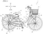
FIG. 1 is a side view showing an electric assist bicycle according to an embodiment of the present invention. -
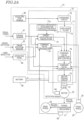
FIG. 2A is a hardware block diagram of the electric assist bicycle. -
FIG. 2B is a block diagram showing a mechanical structure of the electric assist bicycle. -
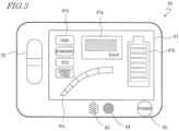
FIG. 3 is an external view of an operation panel. -
FIG. 4 shows the relationship among the rotation angle of a crankshaft, the torque generated at the crankshaft and the acceleration in a travel direction of the vehicle. -
FIG. 5A shows an operation of decreasing a deviation En between a target acceleration and a current acceleration of the vehicle to generate assist power in accordance with a running load (headwind). -
FIG. 5B shows an operation of decreasing the deviation En between the target acceleration and the current acceleration of the vehicle to generate assist power in accordance with a running load (ascending slope). -
FIG. 6 shows the relationship between a pedal force provided by the human (torque signal) and the target acceleration. -
FIG. 7 shows the relationship between the pedal force provided by the human (torque signal) and the target acceleration defined for each of N pieces of selectable assist modes. -
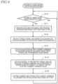
FIG. 8 is a flowchart showing a procedure of a process performed by acontrol device 70. -
FIG. 9 shows waveforms of various signals when a load change occurs while the rider is pedaling theelectric assist bicycle 1 in a certain pedaling manner. -
FIG. 10 shows waveforms of various signals when a load change occurs while the rider is pedaling theelectric assist bicycle 1 in the certain pedaling manner. -
FIG. 11A is a static load correlation diagram of theelectric assist bicycle 1 on a flat road. -
FIG. 11B is a static load correlation diagram of theelectric assist bicycle 1 on a slope having an inclination angle θ. -
FIG. 12 shows a target acceleration (solid line) in the case where a low-frequency component is not removed by a high-pass filter 73. -
FIG. 13 shows a motor torque in accordance with the magnitude of the deviation in the acceleration. - Hereinafter, embodiments of an electric assist system and an electric assist vehicle according to the present invention will be described with reference to the attached drawings. In the description of the embodiments, like elements will bear like reference signs, and overlapping descriptions will be omitted. In the embodiments of the present invention, the terms front, rear, left, right, up and down respectively refer to front, rear, left, right, up and down as seen from a rider, of the electric assist vehicle, sitting on a saddle (seat) as facing a handle. The following embodiments are examples, and the present invention is not limited to any of the following embodiments but to the appended claims.
-
FIG. 1 is a side view showing anelectric assist bicycle 1 according to this embodiment. Theelectric assist bicycle 1 includes a drivingunit 51 described in detail below. Theelectric assist bicycle 1 is an example of electric assist vehicle according to the present invention. The drivingunit 51 is an example of electric assist system according to the present invention. - The
electric assist bicycle 1 includes avehicle frame 11 extending in a front-rear direction. Thevehicle frame 11 includes ahead pipe 12, a down tube 5, a bracket 6, achain stay 7, aseat tube 16, and aseat stay 19. Thehead pipe 12 is located at a front end of thevehicle frame 11. Ahandle stem 13 is rotatably inserted into thehead pipe 12. Ahandle 14 is secured to a top end of thehandle stem 13. Afront fork 15 is secured to a bottom end of thehandle stem 13. Afront wheel 25, which is a steering wheel, is rotatably supported at a bottom end of thefront fork 15. Thefront fork 15 is provided with abrake 8 braking thefront wheel 25. Afront basket 21 is provided to the front of thehead pipe 12. Thefront fork 15 is provided with ahead lamp 22. - The down tube 5 extends obliquely rearward and downward from the
head pipe 12. Theseat tube 16 extends upward from a rear end of the down tube 5. Thechain stay 7 extends rearward from a bottom end of theseat tube 16. The bracket 6 connects the rear end of the down tube 5, the bottom end of theseat tube 16 and a front end of the chain stay 7 to each other. - A
seat post 17 is inserted into theseat tube 16, and asaddle 27, on which a rider is to sit, is provided at a top end of theseat post 17. A rear portion of thechain stay 7 supports arear wheel 26, which is a driving wheel, such that therear wheel 26 is rotatable. Abrake 9 braking therear wheel 26 is provided to the rear of thechain stay 7. Astand 29 is provided to the rear of thechain stay 7. While being parked, theelectric assist bicycle 1 is held as standing by thestand 29. The seat stay 19 extends obliquely rearward and downward from a top portion of theseat tube 16. A bottom end of theseat stay 19 is connected with the rear portion of thechain stay 7. The seat stay 19 supports arack 24 provided to the rear of thesaddle 27 and also supports afender 18 covering a top portion of therear wheel 26. Atail lamp 23 is provided to the rear of thefender 18. - The bracket 6, which is located on the
vehicle frame 11, at a position in the vicinity of the center of the vehicle, is provided with the drivingunit 51. The drivingunit 51 includes anelectric motor 53, acrankshaft 57, and acontrol device 70. Abattery 56 supplying power to theelectric motor 53 and the like is mounted on the bracket 6. Thebattery 56 may be supported by theseat tube 16. - The
crankshaft 57 is supported in the state of running throughout the drivingunit 51 in a left-right direction. Crankarms 54 are provided at both of two ends of thecrankshaft 57. Apedal 55 is rotatably provided at a tip of each of thecrank arms 54. - The
control device 70 controls an operation of theelectric assist bicycle 1. Thecontrol device 70 typically includes a semiconductor integrated circuit, such as a microcontroller, a signal processor or the like, that is capable of processing a digital signal. A rotation output of thecrankshaft 57 generated when the rider steps on, and rotates, the pedal 55 with his/her foot is transmitted to therear wheel 26 via achain 28. Thecontrol device 70 controls theelectric motor 53 to generate a driving assist output in accordance with the rotation output of thecrankshaft 57. The assist power generated by theelectric motor 53 is transmitted to therear wheel 26 via thechain 28. Instead of thechain 28, a belt, a shaft or the like may be used. - Now, a specific structure of the
control device 70, and a group of sensors that generate a signal usable to operate thecontrol device 70, will be described in detail. -
FIG. 2A is a hardware block diagram of theelectric assist bicycle 1, mainly showing a structure of thecontrol device 70.FIG. 2A also shows thecontrol device 70 and a peripheral environment thereof. In the peripheral environment, for example, various sensors that output a signal to thecontrol device 70 and the drivingmotor 53 driven as a result of the operation of thecontrol device 70 are shown. - First, the peripheral environment of the
control device 70 will be described. - As described above, the
control device 70 is included in the drivingunit 51.FIG. 2A shows anacceleration sensor 38, atorque sensor 41, acrank rotation sensor 42, and theelectric motor 53, which are also included in the drivingunit 51. Thecontrol device 70 includes acalculation circuit 71, an averagingcircuit 78, and amotor driving circuit 79. Thecalculation circuit 71 receives a torque signal and calculates a target acceleration from the torque signal based on a rule prepared in advance. Thus, thecalculation circuit 71 performs a calculation to determine the magnitude of the assist power to be generated by the electric motor such that a deviation between the target acceleration and a current acceleration is decreased, and outputs a control signal. - The
acceleration sensor 38 detects an acceleration of a vehicle main body of theelectric assist bicycle 1. Theacceleration sensor 38 is, for example, a three-axis acceleration sensor of a piezo resistance type, an electrostatic capacitance type, or a heat sensing type. One such three-axis acceleration sensor is capable of measuring the acceleration in each of three axial directions perpendicular to each other (X-axis, Y-axis and Z-axis directions). An acceleration signal may be a voltage signal in accordance with the magnitude of the acceleration. Theacceleration sensor 38 may include an acceleration calculation circuit (not shown) converting the voltage signal into an acceleration value. The acceleration calculation circuit converts, for example, an output analog voltage signal into a digital voltage signal, and calculates the acceleration from the magnitude of the digital voltage signal. - In this specification, a signal that is output from the
acceleration sensor 38 and represents the detected acceleration is referred to as an "acceleration signal". The acceleration signal may be either an analog voltage signal or a digital voltage signal. Theacceleration sensor 38 may output an acceleration signal as a non-discrete, continuous signal, or may output an acceleration signal as a discrete signal representing the acceleration detected at a predetermined cycle (e.g., at a cycle of 0.1 seconds). - In this specification, the three axial directions perpendicular to each other (X-axis, Y-axis, and Z-axis directions) do not represent an absolute coordinate system but represent a relative coordinate system. More specifically, the three axial directions perpendicular to each other (X-axis, Y-axis and Z-axis directions) are respectively the front-rear direction, the left-right direction, and an up-down direction of the
electric assist bicycle 1 including theacceleration sensor 38. The forward direction of theelectric assist bicycle 1 matches a travel direction thereof, and the up-down direction of theelectric assist bicycle 1 matches a direction perpendicular to a road surface. Therefore, the X axis, the Y axis and the Z axis of theelectric assist bicycle 1 running on a flat road may not match the X axis, the Y axis and the Z axis of theelectric assist bicycle 1 running on a slope. - The three-axis acceleration sensor is an example of the
acceleration sensor 38. A two-axis acceleration sensor capable of measuring an acceleration Gx in the X-axis direction and an acceleration Gz in the Z-axis direction may be adopted as theacceleration sensor 38. A monoaxial acceleration sensor capable of measuring the acceleration Gx in the X-axis direction may be adopted as theacceleration sensor 38. Theacceleration sensor 38 merely needs to be capable of measuring at least the acceleration Gx in the X-axis direction along the travel direction of the vehicle. A plurality of acceleration sensors may be used to detect accelerations in different axial directions respectively. In the example shown inFIG. 2A , theacceleration sensor 38 is located in the drivingunit 51. The position of theacceleration sensor 38 is not limited to this, and theacceleration sensor 38 may be located at any position in theelectric assist bicycle 1. - The
torque sensor 41 detects the human power (pedal force), applied by the rider to each of thepedals 55, as a torque generated at thecrankshaft 57. Thetorque sensor 41 is, for example, a magnetostrictive torque sensor. Thetorque sensor 41 outputs a voltage signal having an amplitude of the magnitude in accordance with the detected torque. Thetorque sensor 41 may include a torque calculation circuit (not shown) that converts the voltage signal into a torque. The torque calculation circuit converts, for example, an output analog voltage signal into a digital voltage signal, and calculates the torque from the magnitude of the digital voltage signal. - In this specification, a signal that is output from the
torque sensor 41 and represents the detected torque is referred to as a "torque signal". The torque signal may be either an analog voltage signal or a digital voltage signal. Thetorque sensor 41 may output a torque signal as a non-discrete, continuous signal, or may output a torque signal as a discrete signal representing the torque detected at a predetermined cycle (e.g., at a cycle of 0.1 seconds). - The
crank rotation sensor 42 detects a rotation angle of thecrankshaft 57. For example, thecrank rotation sensor 42 detects the rotation of thecrankshaft 57 at every predetermined angle and outputs a rectangular wave signal or a sine wave signal. The output signal may be used to calculate a rotation angle and a rotation speed of thecrankshaft 57. For example, a plurality of magnetic bodies having magnetic poles (N pole, S pole) are located around thecrankshaft 57. A hall sensor located at a fixed position converts a change in the magnetic field polarity caused by the rotation of thecrankshaft 57 into a voltage signal. Thecontrol device 70 uses the signal that is output from the hall sensor to count the changes in the magnetic field polarity and calculates the rotation angle and the rotation speed of thecrankshaft 57. Thecrank rotation sensor 42 may include a calculation circuit that calculates the rotation angle and the rotation speed of thecrankshaft 57 from the output signal. - The
motor driving circuit 79 is, for example, an inverter. Themotor driving circuit 79 supplies, from thebattery 56 to theelectric motor 53, an electric current having an amplitude, a frequency, a flow direction or the like in accordance with a motor electric current command value from thecalculation circuit 71. Theelectric motor 53 supplied with the electric current rotates to generate assist power of a determined magnitude. The details of themotor driving circuit 79 will be described below. - The rotation of the
electric motor 53 is detected by amotor rotation sensor 46. Themotor rotation sensor 46 is, for example, a hall sensor, and detects the magnetic field generated by a rotor (not shown) of theelectric motor 53 while the rotor is rotating and outputs a voltage signal in accordance with the strength or the polarity of the magnetic field. In the case where theelectric motor 53 is a brushless DC motor, a plurality of permanent magnets are located in the rotor. Themotor rotation sensor 46 converts a change in the magnetic field polarity caused by the rotation of the rotor into a voltage signal. Thecalculation circuit 71 uses the signal that is output from themotor rotation sensor 46 to count the changes in the magnetic field polarity, and calculates the rotation angle and the rotation speed of the rotor. - The assist power generated by the
electric motor 53 is transmitted to therear wheel 26 via the power transmission mechanism 31. The power transmission mechanism 31 is a name of a group of components including thechain 28, a drivensprocket 32, a drivingshaft 33, atransmission mechanism 36, a one-way clutch 37, a decelerator (not shown) decelerating the rotation of theelectric motor 53, a transmission (not shown) provided on therear wheel 26, and the like described below with reference toFIG. 2B . With the above-described structure, the human power of the rider of theelectric assist bicycle 1 is assisted. - The
calculation circuit 71 receives a detection signal that is output from each of theacceleration sensor 38, thetorque sensor 41 and thecrank rotation sensor 42 and an operation signal that is output from theoperation panel 60, and determines the magnitude of the assist power. Thecalculation circuit 71 transmits a motor electric current command value, based on which the assist power of the determined magnitude is to be generated, to themotor driving circuit 79. As a result, theelectric motor 53 rotates, and the motive power of theelectric motor 53 is transmitted to therear wheel 26. In this manner, the motive power of theelectric motor 53 is added to the human power of the rider. - The detection signal that is output from any of the various sensors is an analog signal. In general, an A/D conversion circuit (not shown) that converts an analog signal into a digital signal may be provided on a stage before the detection signal is input to the
control device 70. The A/D conversion circuit may be provided in each of the sensors, or may be provided on a signal path, in the drivingunit 51, between each of the sensors and thecontrol device 70. Alternatively, the A/D conversion circuit may be provided in thecontrol device 70. - The magnitude of the assist power to be generated by the
electric motor 53 may change in accordance with an assist mode currently selected. The assist mode may be selected by the rider operating theoperation panel 60. - The
operation panel 60 is attached to the handle 14 (FIG. 1 ) of theelectric assist bicycle 1 and is connected with thecontrol device 70 by, for example, a wire cable. Theoperation panel 60 transmits an operation signal, representing the operation made by the rider, to thecontrol device 70, and receives various information to be presented to the rider from thecontrol device 70. - Now, a power transmission route in the
electric assist bicycle 1 will be described.FIG. 2B is a block diagram showing an example of mechanical structure of theelectric assist bicycle 1. - When the rider steps on the pedal 55 to rotate the
crankshaft 57, the rotation of thecrankshaft 57 is transmitted to thesynthesis mechanism 58 via the one-way clutch 43. The rotation of theelectric motor 53 is transmitted to thesynthesis mechanism 58 via thedecelerator 45 and the one-way clutch 44. - The
synthesis mechanism 58 includes, for example, a cylindrical member, and thecrankshaft 57 is located inside the cylindrical member. Thedrive sprocket 59 is attached to thesynthesis mechanism 58. Thesynthesis mechanism 58 rotates as centering around the same rotation shaft as that of thecrankshaft 57 and thedrive sprocket 59. - The one-way clutch 43 transmits a forward rotation of the
crankshaft 57 to thesynthesis mechanism 58, but does not transmits a reverse rotation of thecrankshaft 57 to thesynthesis mechanism 58. The one-way clutch 44 transmits, to thesynthesis mechanism 58, a rotation of theelectric motor 53 in such a direction as to rotate thesynthesis mechanism 58 in a forward direction, but does not transmit, to thesynthesis mechanism 58, a rotation of theelectric motor 53 in such a direction as to rotate thesynthesis mechanism 58 in a reverse direction. In the case where the rider rotates the pedal 55 to rotate thesynthesis mechanism 58 while theelectric motor 53 is at a stop, the one-way clutch 44 does not transmit the rotation to theelectric motor 53. The pedal force applied by the rider to thepedal 55 and the assist power generated by theelectric motor 53 are transmitted to thesynthesis mechanism 58 to be synthesized. The resultant force synthesized by thesynthesis mechanism 58 is transmitted to thechain 28 via thedrive sprocket 59. - The rotation of the
chain 28 is transmitted to the drivingshaft 33 via the drivensprocket 32. The rotation of the drivingshaft 33 is transmitted to therear wheel 26 via thetransmission mechanism 36 and the one-way clutch 37. - The
transmission mechanism 36 is a mechanism that changes the transmission gear ratio in accordance with the operation of the rider made on atransmission operator 67. Thetransmission operator 67 is attached to, for example, the handle 14 (FIG. 1 ). In the case where the rotation speed of the drivingshaft 33 is higher than the rotation speed of therear wheel 36, the one-way clutch 37 transmits the rotation of the drivingshaft 33 to therear wheel 26. In the case where the rotation speed of the drivingshaft 33 is lower than the rotation speed of therear wheel 36, the one-way clutch 37 does not transmit the rotation of the drivingshaft 33 to therear wheel 26. - With the above-described power transmission route, the pedal force applied by the rider on the
pedal 55 and the assist power generated by theelectric motor 53 are transmitted to therear wheel 26. -
FIG. 3 is an illustrate external view of theoperation panel 60. Theoperation panel 60 is attached to, for example, thehandle 14, at a position close to a left grip thereof. - The
operation panel 60 includes adisplay panel 61, an assistmode operation switch 62, and apower source switch 65. - The
display panel 61 is, for example, a liquid crystal panel. Thedisplay panel 61 displays information provided by thecontrol device 70 that includes the speed of theelectric assist bicycle 1, the remaining capacitance of thebattery 56, information on the range in which the assist ratio is to be changed, the assist mode, and other information on the running. - The
display panel 61 includes aspeed display area 61a, a battery remainingcapacitance display area 61b, an assist ratio changerange display area 61c, and an assistmode display area 61d. Thedisplay panel 61 acts as a notification device that notifies the rider of such information and the like. In this example, the information is displayed. Alternatively, an audio signal may be output to notify the rider of the information. - The
speed display area 61a displays the vehicle speed of theelectric assist bicycle 1 by numerical figures. In this embodiment, the vehicle speed of theelectric assist bicycle 1 is detected by aspeed sensor 35 provided on thefront wheel 25. - The battery remaining
capacitance display area 61b displays the remaining capacitance of thebattery 56 by segments based on information on the battery remaining capacitance that is output from thebattery 56 to thecontrol device 70. With such display, the rider intuitively grasps the remaining capacitance of thebattery 56. - The assist ratio change
range display area 61c displays the range, set by thecontrol device 70, in which the assist ratio is to be changed. The range is displayed by segments. The assist ratio, within the change ratio, that is currently used may also be displayed. - The assist
mode display area 61d displays the assist mode selected by the rider operating the assistmode operation switch 62. The assist mode is, for example, "high", "standard" or "automatic ecological". In the case where the rider operates the assistmode operation switch 62 to select "assist mode off", the assistmode display area 61d displays "assist-free". - The assist
mode selection switch 62 is for the rider to select one of the plurality of assist modes (including "assist mode off") described above. When one of the plurality of assist modes is selected, a microcontroller (not shown) provided inside theoperation panel 60 transmits an operation signal, specifying the selected assist mode, to thecontrol device 70. - The
power source switch 65 is a switch by which the power source of theelectric assist bicycle 1 is switched on or off. The rider presses the power source switch 65 to switch the power source of theelectric assist bicycle 1 on or off. - The
operation panel 60 further includes aspeaker 63 providing necessary information to the rider by an audio signal and alamp 64 providing necessary information to the rider by light. For example, thecontrol device 70 changes the magnitude of the assist power to be generated by theelectric motor 53 in accordance with the change in the acceleration, which is associated with the operation of the rider rotating thepedal 55. At this point, it is notified to the rider by, for example, the output of an audio signal and/or blinking of light, that the magnitude of the assist power has been changed. As a result of the notification, the rider recognizes that, for example, large assist power has been generated. Alternatively, thehandle 14 and/or thesaddle 27 may be vibrated to notify the rider that the magnitude of the assist power has been changed. - While the assist power is increasing, the
speaker 63 may be caused to generate an audio signal of a volume that is heard by people around theelectric assist bicycle 1, or thehead lamp 22 and thetail lamp 23 may be lit up or blinked. With such an arrangement, the people around theelectric assist bicycle 1 recognize that theelectric assist bicycle 1 is generating assist power larger than the usual assist power. - The assist power of the
electric motor 53 is largest in the "high" mode, is smallest in the "automatic ecological" mode, and is middle in the "standard" mode in response to the crank rotation output. - In the case where the assist mode is "standard", the
electric motor 53 generates assist power when, for example, theelectric assist bicycle 1 is to start, is running on a flat road, or is running on an ascending slope. In the case where the assist mode is "high", theelectric motor 53 generates assist power when, for example, theelectric assist bicycle 1 is to start, is running on a flat road, or is running on an ascending slope, like in the case where the assist mode is "standard". In the case where the assist mode is "high", theelectric motor 53 generates larger assist power than in the case where the assist mode is "standard" in response to the same crank rotation output. In the case where the assist mode is "automatic ecological", when, for example, theelectric assist bicycle 1 is to start on a flat road, theelectric motor 53 generates assist power smaller than that in the case where the assist mode is "standard", and when theelectric assist bicycle 1 is running on an ascending slope, theelectric motor 53 generates assist power larger than that in the case where the assist mode is "standard". When the pedal force is small because theelectric assist bicycle 1 is, for example, running on a flat road or on a descending slope, theelectric motor 53 decreases the assist power as compared with in the case where the assist mode is "standard" or stops the generation of the assist power to suppress the power consumption. In the case where the assist mode is "assist-free mode", theelectric motor 53 does not generate any assist power. - As described above, the assist power in response to the crank rotation output is varied in accordance with the assist mode described above. In this example, the assist mode is switched to any one of four stages. Alternatively, the assist mode may be switched to any of three stages or less, or any of five stages or more.
- Now, an operation of changing the magnitude of the assist power to be generated by the
electric motor 53 in accordance with the acceleration, which changes in association with the operation of the rider rotating the pedal 55, will be described. - First, the relationship between the operation of the rider rotating the pedal 55 and the acceleration will be described.
FIG. 4 shows the relationship among the rotation angle of thecrankshaft 57, the torque generated at thecrankshaft 57 and the acceleration in the travel direction of the vehicle while the rider is rotating thepedal 55. In the example shown inFIG. 4 , theelectric assist bicycle 1 is running on a flat road, and the direction from left to right in the figure is assumed to be a travel direction x of the vehicle. - Because of the structure of the
electric assist bicycle 1 of allowing the rider to have his/her foot step on, and rotate, thepedal 55, the magnitude of the human power (pedal force) of the rider applied to thepedal 55 is increased or decreased in accordance with the position of the pedal 55, namely, the rotation angle of thecrankshaft 57. The increase or the decrease in the pedal force applied to thepedal 55 appears as increase or decrease in the torque generated at thecrankshaft 57. When the torque is increased or decreased, the motive power that runs theelectric assist bicycle 1 is increased or decreased. Therefore, the acceleration in the travel direction x of theelectric assist bicycle 1 is increased or decreased in accordance with the increase or the decrease in the torque. - (a) of
FIG. 4 shows a state where aright pedal 55R of theelectric assist bicycle 1, on which the rider puts his/her right foot, is located just above thecrankshaft 57, whereas aleft pedal 55L of theelectric assist bicycle 1, on which the rider puts his/her left foot, is located just below thecrankshaft 57. The rotation angle of thecrankshaft 57 at this point is set as 0 degrees. In this state, the torque generated at thecrankshaft 57 by the human power is minimum. In association with the torque, the acceleration in the travel direction x is also minimum. - From the state shown in (a) of
FIG. 4 , the rider steps on theright pedal 55R, and as a result, the rotation angle of thecrankshaft 57 is increased. As the rotation angle of thecrankshaft 57 is increased, the torque generated at thecrankshaft 57 by the human power is gradually increased. As the torque is gradually increased, the acceleration in the travel direction x of the vehicle is also increased. - (b) of
FIG. 4 shows a state where theright pedal 55R is located to the front, in a horizontal direction, of thecrankshaft 57, whereas theleft pedal 55L is located to the rear, in the horizontal direction, of thecrankshaft 57. The rotation angle of thecrankshaft 57 at this point is set as 90 degrees. When the rotation angle is 90 degrees, the torque generated at thecrankshaft 57 by the human power is maximum. In association with the torque, the acceleration in the travel direction x of the vehicle is also maximum. - From the state shown in (b) of
FIG. 4 , the rotation angle of thecrankshaft 57 is further increased. As the rotation angle of thecrankshaft 57 is increased, the torque generated at thecrankshaft 57 by the human power is gradually decreased. As the torque is gradually decreased, the acceleration in the travel direction x of the vehicle is also decreased. - (c) of
FIG. 4 shows a state where theright pedal 55R is located just below thecrankshaft 57, whereas theleft pedal 55L is located just above thecrankshaft 57. The rotation angle of thecrankshaft 57 at this point is set as 180 degrees. When the rotation angle is 180 degrees, the torque generated at thecrankshaft 57 by the human power is minimum. In association with the torque, the acceleration in the travel direction x of the vehicle is also minimum. - From the state shown in (c) of
FIG. 4 , the rider steps on theleft pedal 55L, and as a result, the rotation angle of thecrankshaft 57 is further increased. As the rotation angle of thecrankshaft 57 is increased, the torque generated at thecrankshaft 57 by the human power is gradually increased. As the torque is gradually increased, the acceleration in the travel direction x of the vehicle is also increased. - (d) of
FIG. 4 shows a state where theleft pedal 55L is located to the front, in the horizontal direction, of thecrankshaft 57, whereas theright pedal 55R is located to the rear, in the horizontal direction, of thecrankshaft 57. The rotation angle of thecrankshaft 57 at this point is set as 270 degrees. When the rotation angle is 270 degrees, the torque generated at thecrankshaft 57 by the human power is maximum. In association with the torque, the acceleration in the travel direction x of the vehicle is also maximum. - From the state shown in (d) of
FIG. 4 , the rotation angle of thecrankshaft 57 is further increased. As the rotation angle of thecrankshaft 57 is increased, the torque generated at thecrankshaft 57 by the human power is gradually decreased. As the torque is gradually decreased, the acceleration in the travel direction x of the vehicle is also decreased. - (e) of
FIG. 4 shows a state where theright pedal 55R is located just above thecrankshaft 57, whereas theleft pedal 55L is located just below thecrankshaft 57. Namely, (e) ofFIG. 4 shows a state where thecrankshaft 57 has made one rotation from the state shown in (a) ofFIG. 4 . The rotation angle of thecrankshaft 57 at this point is set as 0 degrees. When the rotation angle is 0 degrees, the torque generated at thecrankshaft 57 by the human power is maximum. In association with the torque, the acceleration in the travel direction x of the vehicle is also maximum. - In this manner, the torque generated at the
crankshaft 57 increases or decreases in accordance with the rotation angle of thecrankshaft 57. In the torque that increases and decreases, a ridge and a trough appear alternately. In synchronization with the increase and the decrease in the torque, the acceleration in the travel direction x of the vehicle increases and decreases. In synchronization with the timings when the ridge and the trough of the torque appear, a ridge and a trough appear alternately in the acceleration that increases and decreases. - In a zone between the ridge and the trough, adjacent to each other, of the torque, a peak of the ridge represents the maximum value of the torque in the zone. A bottom of the trough of the torque represents the minimum value of the torque in the zone. In this specification, the zone between the ridge and the trough adjacent to each other includes the peak of the ridge and the bottom of the trough.
- In a zone between the ridge and the trough, adjacent to each other, of the acceleration, a peak of the ridge represents the maximum value of the acceleration in the zone. A bottom of the trough of the acceleration represents the minimum value of the acceleration in the zone. In synchronization with the timings at which the ridge and the trough, adjacent to each other, of the torque that increases and decreases appear, the maximum value and the minimum value of the acceleration appear.
- The rider riding the
electric assist bicycle 1 adjusts the pedal force to be applied to thepedal 55 and the speed at which thepedal 55 is to be rotated, so as to accelerate theelectric assist bicycle 1 with the sense of acceleration desired by the rider and thus to run theelectric assist bicycle 1 at the speed desired by the rider. In this specification, the manner of the rider pedaling theelectric assist bicycle 1 with a torque changing periodically as shown inFIG. 4 will be referred to as a "certain pedaling manner". - While the rider is pedaling the
electric assist bicycle 1 on a flat road in the certain pedaling manner, the rider is considered to wish to run theelectric assist bicycle 1 at an acceleration changing periodically as shown inFIG. 4 . Meanwhile, theelectric assist bicycle 1 is influenced by various external disturbances. For this reason, the acceleration changing periodically as shown inFIG. 4 may not be obtained. For example, a headwind caused by the running of theelectric assist bicycle 1, a wind meteorologically generated and/or a slope are all examples of the external disturbances. - The present inventor conceived adjusting the assist power of the
electric assist bicycle 1 such that while the rider is pedaling theelectric assist bicycle 1 in the certain pedaling manner, the rider runs theelectric assist bicycle 1 with the sense of acceleration changing periodically as shown inFIG. 4 regardless of whether there is any external disturbance or not. The "sense of acceleration" used in this specification refers to the sense of speed that the rider feels by increase or decrease in the speed in the travel direction while running theelectric assist bicycle 1 with the acceleration changing periodically as shown inFIG. 4 . The "sense of acceleration" is different from the acceleration detected by theacceleration sensor 38. As described below, on a slope, theacceleration sensor 38 detects an acceleration in accordance with the inclination. Therefore, even when theelectric assist bicycle 1 is at a stop, theacceleration sensor 38 outputs a certain value that is not zero. For this reason, even if theelectric assist bicycle 1 runs with exactly the same change in the speed on a flat road and on a slope, the acceleration detected by theacceleration sensor 38 on the flat road, and the acceleration detected byacceleration sensor 38 on the slope, do not match each other. However, if the assist power is adjusted appropriately, the rider running with an influence of an external disturbance, for example, the rider running on a slope, may pedal theelectric assist bicycle 1 with the same sense of acceleration as that on the flat road. The "same sense of acceleration" may be rephrased as, for example, the same average speed per hour in a certain time period. In an embodiment of the present invention, the rider is allowed to drive theelectric assist bicycle 1 with the same sense of acceleration while running on a flat road and while running with a load. - Hereinafter, an overview of an operation of the
electric assist bicycle 1 according to this embodiment willbe described with reference toFIG. 5A andFIG. 5B . -
FIG. 5A shows an example of motion of theelectric assist bicycle 1 in the case where the rider is subjected to a headwind as a load. It is assumed that there is no wind up to a certain time point, and then the rider is subjected to the headwind at the timing represented by the dotted line parallel to the up-down direction of the figure. - (a) of
FIG. 5A schematically shows a waveform of a value of the torque obtained based on the torque signal. As understood from the waveform in (a) ofFIG. 5A , the rider rides theelectric assist bicycle 1 in the certain pedaling manner. In this embodiment, thecontrol device 70 calculates a target acceleration from the torque signal, and determines the magnitude of the assist power to be generated by theelectric motor 53 such that the deviation between the target acceleration and the current acceleration is decreased. - The present inventor considered that the value of the torque represented by the torque signal is a value directly indicating with what acceleration the rider wishes to drive the
electric assist bicycle 1, and set a map or a function defining the correspondence between the torque signal and the target acceleration. The map or function may be used to determine the target acceleration uniquely from the value of the torque. - (b) of
FIG. 5A schematically shows a waveform of the target acceleration calculated based on the torque. In general, as the value of the torque is smaller, the target acceleration is smaller; whereas as the value of the torque is larger, the target acceleration is larger. The value of the target acceleration may be increased or decreased in synchronization with the value of the torque. - (c) of
FIG. 5A schematically shows the acceleration in the travel direction x of the vehicle. The solid line represents a waveform of the acceleration signal that is output from theacceleration sensor 38, and the dashed line represents the waveform of the target acceleration. Hereinafter, a difference between the ridge and the trough, adjacent to each other, of the acceleration at time t will be referred to as "P-P(t)", for example. - The difference P-P(t) and a difference P-P(t+1) will be compared against each other. The acceleration value of the latter has a larger amplitude in the negative direction. Therefore, the deviation En(t+1) between the acceleration value and the target acceleration value at time (t+1) is relatively large.
- In this embodiment, the
control device 70 determines the magnitude of the assist power to be generated by theelectric motor 53 such that the deviation En(t+1) is decreased. The term "decreased" refers to, for example, "made 0 (zero)". - After the
electric assist bicycle 1 is subjected to the headwind, thecontrol device 70 generates larger assist power. As a result, at time (t+2), a deviation En(t+2) is converged to approximately 0. This indicates that the rider is subjected to the headwind but maintains the same acceleration as long as keeping on pedaling theelectric assist bicycle 1 with the same pedal force (torque). -
FIG. 5B shows an example of motion of theelectric assist bicycle 1 in the case where the rider receives, from a slope, a downward force parallel to the inclining surface as a load. It is assumed that theelectric assist bicycle 1 runs on a flat road up to a certain time point and then, starts running on a slope at the timing represented by the dotted line parallel to the up-down direction of the figure. (b) and (c) ofFIG. 5B respectively show the target acceleration and the current acceleration. In each of (b) and (c) ofFIG. 5B , the waveform after theelectric assist bicycle 1 starts running on the slope is provided as a waveform obtained as a result of removing, by a high-pass filter, a low-frequency component of the acceleration which is added in accordance with the slope. This process will be described below in detail. - (a) of
FIG. 5B schematically shows a waveform of a value of the torque obtained based on the torque signal. As understood from the waveform in (a) ofFIG. 5B , the rider rides theelectric assist bicycle 1 in the certain pedaling manner on a flat road, but pedals theelectric assist bicycle 1 with a larger pedal force immediately after the start of the slope. Such a manner of pedaling is common. A reason for this is that before and after the start of the slope, the rider expects that the speed will be decreased due to the ascending slope, and intuitively pedals theelectric assist bicycle 1 strongly. - (b) of
FIG. 5B schematically shows a waveform of the target acceleration calculated based on the torque. As described above regarding (b) ofFIG. 5A , as the value of the torque is smaller, the target acceleration is smaller; whereas as the value of the torque is larger, the target acceleration is larger. It is understood that in synchronization with the larger pedal force immediately after the start of the slope, the target acceleration is calculated to be larger than that before the start of the slope. - (c) of
FIG. 5B schematically shows the acceleration in the travel direction x of the vehicle. The solid line represents a waveform of the acceleration signal that is output from theacceleration sensor 38, and the dashed line represents the waveform of the target acceleration. - The difference P-P(t) and the difference P-P(t+1) will be compared against each other. The acceleration value of the latter has a larger amplitude in the negative direction. Therefore, the deviation En(t+1) between the acceleration value and the target acceleration value at time (t+1) is relatively large.
- The
control device 70 determines the magnitude of the assist power to be generated by theelectric motor 53 such that the deviation En(t+1) is decreased. In this example also, the term "decreased" refers to, for example, "made 0 (zero)". - After the
electric assist bicycle 1 starts running on the slope, thecontrol device 70 generates larger assist power. As a result, the difference P-P(t+2) is smaller than the difference P-P(t+1). However, the difference P-P(t+2) is not converged to 0. Therefore, thecontrol device 70 further determines the magnitude of the assist power to be generated by theelectric motor 53 such that the deviation En(t+2) between the acceleration value and the target acceleration value at time (t+2) is decreased. As a result of such a process, the deviation regarding theelectric assist bicycle 1 after time (t+2) is converted to approximately 0. - As the
electric assist bicycle 1 advances on the slope, theelectric motor 53 generates larger assist power. Therefore, the rider gradually decreases the pedal force (torque) and as a result, returns the pedal force to the level on the flat road. After starting running on the slope, the rider may return the pedal force (torque) to the same level of pedal force as that on the flat road within a sufficiently short time period, and may still obtain the same sense of acceleration as that on the flat road. - With the above-described control, the rider does not need to pedal the
electric assist bicycle 1 strongly when the load is heavy, and theelectric assist bicycle 1 is prevented from jumping out due to excessively large assist power when the load is light. Namely, the rider may obtain a desired sense of acceleration, which is substantially the same as that on the flat road, regardless of whether the load is heavy or light as long as keeping on riding theelectric assist bicycle 1 in the certain pedaling manner. - Now, an internal structure of the
control device 70 will be described with reference toFIG. 2A again, and then, an operation performed by thecontrol device 70 will be described. - As described above, the
control device 70 includes thecalculation circuit 71, the averagingcircuit 78, and themotor driving circuit 79. Thecalculation circuit 71 will be described as being an integrated circuit including a plurality of circuits in this embodiment, but such a structure is an example. A process realized by one or a plurality of circuits may be realized by a software process by use of one signal processor. - The averaging
circuit 78 is a digital filtering circuit that smooths a detection signal regarding each of the axial directions that is output from theacceleration sensor 38. The averagingcircuit 78 may, for example, calculate a moving average of a plurality of detection signals to smooth the detection signals. Another smoothing algorithm may be used. In this embodiment, the averagingcircuit 78 is provided. Nonetheless, according to the present invention, it is not indispensable to provide the averagingcircuit 78. - The
calculation circuit 71 performs a calculation of finding a motor electric current command value from the assist mode or the like, performs a calculation of finding a target acceleration based on the torque, performs a calculation of finding a motor torque at which the deviation between the target acceleration and the current acceleration is decreased and correcting the motor electric current command value such that the obtained motor torque is generated, performs a calculation of further correcting the corrected motor command value in consideration of a condition such as the speed or the like, and outputs a control signal. - In this embodiment, the
calculation circuit 71 includes blocks performing a plurality of types of processes. Specifically, thecalculation circuit 71 includes a targetacceleration calculation block 72, a high-pass filter 73, a motor electric current commandvalue calculation block 74, motor electric current command value correction blocks 75 and 76, and astorage block 77. Each of the blocks other than thestorage block 77 may be mounted as a calculation core in thecalculation circuit 71, or may be mounted as a sub routine or a library of a computer program. - The target
acceleration calculation block 72 receives a torque signal from thetorque sensor 41, and refers to anacceleration calculation rule 77a stored in advance on thestorage block 77 described below to calculate the target acceleration from the torque signal. -
FIG. 6 shows an example of theacceleration calculation rule 77a representing the relationship between the pedal force provided by the human (torque signal) and the target acceleration. As described above, the present inventor considered that once the pedal force of the rider is found, the acceleration desired by the rider is specified uniquely. Thus, the present inventor prepared, in advance, the correspondence between the pedal force provided by the human (torque signal) and the target acceleration in the form of theacceleration calculation rule 77a, and stored theacceleration calculation rule 77a on thestorage block 77. The targetacceleration calculation block 72 refers to theacceleration calculation rule 77a to calculate the target acceleration based on the pedal force obtained from thetorque sensor 41. - In
FIG. 6 , the correspondence between torque signal and the target acceleration is represented as a nonlinear continuous function. This is an example. The correspondence between torque signal and the target acceleration may be represented as a linear continuous function, or may be represented by a map or a table that associates the signal value of the torque signal and the target acceleration in a one-to-one manner. - The example shown in
FIG. 6 may be extended. In the case where any assist mode is selectable, a different function, map or table may be selected in accordance with the selected assist mode. -
FIG. 7 shows the relationship between the pedal force provided by the human (torque signal) and the target acceleration that is defined for each of the N pieces of selectable assist modes. It is assumed that the assist ratio is lowest inassist mode 1 and is highest in assist mode N. In the example shown inFIG. 7 , as the assist mode is of a higher assist ratio, a larger target acceleration may be set for the same pedal force. - Specific profiles in
FIG. 6 andFIG. 7 may be appropriately determined by a designer or a producer of theelectric assist bicycle 1 based on the specifications or the like of theelectric assist bicycle 1. In other words, unless the specifications of theelectric assist bicycle 1 are determined, the specific profiles inFIG. 6 andFIG. 7 are not determined. A reason for this is that even with the same pedal force, the acceleration performance significantly varies in accordance with, for example, the diameter, the number of teeth or the like of each of the sprocket (not shown) attached to the crankshaft and the sprocket (not shown) attached to the rear wheel. - The motor electric current command
value calculation block 74 calculates the motor electric current command value, based on which subsequent processes are to be performed. In general, the magnitude of the torque to be generated by theelectric motor 53 is in proportion to the level of the electric current to flow in theelectric motor 53. Once the level of the electric current that is to flow in theelectric motor 53 is determined, the magnitude of the torque to be generated is determined uniquely. Namely, determining the motor electric current command value is determining the magnitude of the torque to be generated by theelectric motor 53. - First, a method for calculating the motor electric current command value will be generally described, and then will be described in detail. The motor electric current command
value calculation block 74 receives data specifying the assist mode selected by the rider by use of theoperation panel 60, and sets the assist mode. A reason for this is that the map or rule to be used to determine the motor electric current command value is different in accordance with the assist mode. The motor electric current commandvalue calculation block 74 also receives a value representing the magnitude of the pedal torque detected by thetorque sensor 41. The magnitude of the pedal torque is one of parameters usable to determine the assist power. The motor electric current commandvalue calculation block 74 further receives, from a transmissiongear range sensor 48, data representing the transmission gear range of the transmission. The transmissiongear range sensor 48 detects the transmission gear range of the transmission included in the power transmission mechanism 31. The magnitude of the assist power to be applied to the ground by therear wheel 26 changes in accordance with the level of the transmission gear range. Therefore, the output value of the transmissiongear range sensor 48 is also considered to be one of the basic parameters usable to calculate the motor electric current command value. The motor electric current commandvalue calculation block 74 further receives speed data from thespeed sensor 35. - The motor electric current command
value calculation block 74 determines the motor electric current command value such that the ratio between the torque to be generated at a driving shaft of therear wheel 26 by the pedal force and the torque to be generated at the driving shaft of therear wheel 26 by the drivingmotor 53 matches the assist ratio. The "assist ratio" is a ratio of the assist output generated by theelectric motor 53 with respect to the crank rotation output that is generated by the human power of the rider applied to thepedal 55. The assist ratio may also be referred to as a "driving assist ratio". - The motor electric current command
value calculation block 74 finds the motor electric current command value such that, for example, the torque to be generated at the driving shaft of therear wheel 26 by the pedal force and the torque to be generated at the driving shaft of therear wheel 26 by the drivingmotor 53 are equal to each other (assist ratio is 1:1). The motor electric current command value may be found by use of, for example, a predefined "table representing the relationship between the human power torque and the motor electric current command value". In this process, the motor electric current commandvalue calculation block 74 calculates the motor electric current command value further in consideration of the deceleration ratio of the decelerator that decelerates the rotation of theelectric motor 53. When, for example, the deceleration ratio is N, the motor electric current commandvalue calculation block 74 calculates the motor electric current command value such that a motor torque that is 1/N of the torque to be generated at the driving shaft of therear wheel 26 by the pedal force is generated. When, for example, the deceleration ratio is 2, the motor electric current commandvalue calculation block 74 calculates the motor electric current command value such that a motor torque that is 1/2 of the torque to be generated at the driving shaft of therear wheel 26 by the pedal force is generated. - Next, the motor electric current command
value calculation block 74 multiplies the motor electric current command value by a coefficient in accordance with the assist mode set by the user. For example, the coefficient is set to 2 when the assist mode is "high", the coefficient is set to 1 when the assist mode is "standard", and the coefficient is set to 0.8 when the assist mode is "low". With such settings, the motor electric current commandvalue calculation block 74 multiplies the motor electric current command value by the coefficient corresponding to the assist mode set by the user. - Next, the motor electric current command
value calculation block 74 corrects the motor electric current command value in consideration of the vehicle speed. In the case where, for example, the vehicle speed is low, the motor electric current commandvalue calculation block 74 sets the motor electric current command value to be relatively large. As the vehicle speed is increased, the motor electric current commandvalue calculation block 74 decreases the motor electric current command value. The motor electric current commandvalue calculation block 74 sets the motor electric current command value in this manner, so that the assist power at the start of the vehicle is increased and thus the feel of driving is improved. - Next, the motor electric current command
value calculation block 74 corrects the motor electric current command value in consideration of the transmission gear range. In the case where, for example, the current transmission gear range is lower than, or equal to, a predefined transmission gear range, the motor electric current commandvalue calculation block 74 may set the level of the electric current that is to flow in theelectric motor 53 to be relatively low. With such a setting, the magnitude of the assist power to be generated by theelectric motor 53 is suppressed, and the acceleration of the vehicle is prevented from becoming excessively large. Thus, the feel of driving is improved. - The motor electric current command
value calculation block 74 may calculate the transmission gear range from the rotation speed of theelectric motor 53 and the running speed of the vehicle main body. The motor electric current commandvalue calculation block 74 calculates the transmission gear range by use of the output signal of themotor rotation sensor 46 and the output signal of thespeed sensor 35. In this case, the transmissiongear range sensor 48 may be omitted. - The above-described order of the processes performed by the motor electric current command
value calculation block 74 is merely an example. The processes may be performed in an order different from the above. For example, the motor electric current commandvalue calculation block 74 may first correct the motor electric current command value in consideration of the transmission gear range and then correct the motor electric current command value in consideration of the vehicle speed. Provision of the transmissiongear range sensor 48 is not indispensable in this embodiment. The motor electric current commandvalue calculation block 74 outputs the motor electric current command value to the motor electric current commandvalue correction block 75. - Now, the high-
pass filter 73 will be described. The high-pass filter 73 is a digital filter that transmits a component of a predefined frequency, for example, a high-frequency component of 5 Hz or higher. It should be noted that in the case where an analog acceleration signal is input to the high-pass filter 73, the high-pass filter 73 is an analog filter. The basis for "5 Hz" mentioned above will be described briefly. Assuming that the cadence is 200 rpm at the maximum, the pedal makes 3.3 rotations per second. Namely, the rotation of the pedal is 3.3 Hz. With a margin of about 1.5 times this value, the value "5 Hz" is determined. The value does not need to be precisely 5 Hz, and may be appropriately adjusted by a person of ordinary skill in the art. - The motor electric current command
value correction block 75 receives the motor electric current command value calculated by the motor electric current commandvalue calculation block 74, the value of the target acceleration that is output from the targetacceleration calculation block 72, and the value of the acceleration sensor 38 (value of the detected acceleration) that is output from the high-pass filter 73. The motor electric current commandvalue correction block 75 corrects the motor electric current command value such that the detected acceleration matches the target acceleration. - An overview of a method for correction is as follows.
- Correction method (a): in the case where the detected acceleration is smaller than the target acceleration, the motor electric current command
value correction block 75 increases the motor electric current command value by correction. - Correction method (b): in the case where the detected acceleration is maintained at the target acceleration, the motor electric current command
value correction block 75 maintains the motor electric current command value. - Correction method (c): in the case where the detected acceleration is larger than the target acceleration, the motor electric current command
value correction block 75 decreases the motor electric current command value by correction. - In this embodiment, PID control is used as one of processes suitable to the above-described correction method. The motor electric current command
value correction block 75 uses the PID control to calculate the motor torque to be generated by theelectric motor 53. Next, the motor electric current commandvalue correction block 75 determines the motor electric current command value that is required to generate the calculated motor torque, and finds the difference between the determined motor electric current command value and the current motor electric current command value. The difference may be of a positive value, 0, or of a negative value. - The process performed by the motor electric current command
value correction block 75 will be described specifically. Now, feedback gains of a proportional element, a differential element and an integration element of the drivingunit 51 are respectively represented as Kp, Kd and Ki. The current deviation at the time t is represented as e (t) . - The motor electric current command
value correction block 75 determines the motor torque Fm, corresponding to the assist power to be generated, by theelectric motor 53 by the following expression.
- The first term of the right side represents a calculation regarding the proportional element (proportion control calculation). In general, the proportion control calculation is used to smoothly make a current value close to a target value. As the deviation is decreased, namely, as the current value is made closer to the target value, the amount of operation based on the proportion control calculation is decreased. The motor electric current command
value correction block 75 determines the torque of a magnitude in proportion to the immediately previous deviation. - The second term of the right side represents a calculation regarding the integration element (integration control calculation). In the above-described proportion control calculation, the amount of operation is decreased as the current value is made closer to the target value. Therefore, the deviation remains. The integration control calculation is used to further decrease such a residual deviation. As a result of the integration control calculation, the residual deviation is temporally accumulated. When the residual deviation reaches a certain magnitude, the amount of operation may be increased to further decrease the residual deviation. The motor electric current command
value correction block 75 determines the torque of a magnitude in proportion to the accumulated value of the residual deviation. - The third term of the right side represents a calculation regarding the differential element (differential control calculation). In general, the differential control calculation is used to improve the responsiveness (speed of response) when an external disturbance occurs. When the difference between the immediately previous deviation and the current deviation is increased by a sudden external disturbance, the amount of operation is increased in accordance with the difference to improve the ability of following a change caused by the external disturbance. The motor electric current command
value correction block 75 determines the torque of a magnitude in proportion to the differential of the residual deviation. - The feedback gains Kp, Kd and Ki of the proportion element, the differential element and the integration element may vary in accordance with the performance of the
electric motor 53, the specifications of the power transmission mechanism of theelectric assist bicycle 1, or the like. In a model at the time of designing the control system, the specifications of theelectric assist bicycle 1 are deeply related with, for example, how the waste time until the rise of control response, the time constant, and the steady-state value to be converged are to be set. This is also applicable to how the feedback gains Kp, Kd and Ki are to be set. - Upon calculating the motor torque Fm by
expression 1 shown above, the motor electric current commandvalue correction block 75 finds the motor electric current command value required to generate the motor torque Fm. The relationship between the motor torque Fm and the electric current command value is available in advance as an index that represents the performance of theelectric motor 53. The motor electric current commandvalue correction block 75 holds, in advance, a motor torque - electric current command value correspondence table, which represents the relationship. The motor electric current commandvalue correction block 75 refers to the table to find the electric current command value required to generate the motor torque Fm obtained byexpression 1. Then, the motor electric current commandvalue correction block 75 corrects the electric current command value such that the current electric current command value becomes such a newly found electric current command value. - The left side of
expression 1 shown above represents the motor torque Fm. Alternatively, the electric current command value may be directly found. In this case, the feedback gains Kp, Kd and Ki in the right side ofexpression 1 may be changed to values obtained in consideration of the contents of the motor torque - electric current command value correspondence table mentioned above. Feedback gains to be used to find the electric current command value from the proportion term, the integration term and the differential term regarding the residual deviation will be respectively represented as Kp', Kd' and Ki'. The motor electric current commandvalue correction block 75 may determine an electric current command value Im(t), to be generated by theelectric motor 53, by the followingexpression 2.
- Whether the electric current command value is to be found from the motor torque Fm by use of the motor torque - electric current command value correspondence table or is to be found directly from
expression 1 by changing the feedback gains is an issue of designing. Either method may be adopted. - The motor electric current command
value correction block 75 outputs the motor electric current command value to the motor electric current commandvalue correction block 76. - Now, the motor electric current command
value correction block 76 will be described. The motor electric current commandvalue correction block 76 further corrects the motor electric current command value corrected by the motor electric current commandvalue correction block 75. The purpose of the correction is to gradually decrease the motor torque in accordance with the vehicle speed and to improve the feel of riding in consideration of the crank rotation. Hereinafter, this will be described specifically. - The motor electric current command
value correction block 76 corrects the motor electric current command value in accordance with the vehicle speed. In Japan, there is a regulation that when the vehicle speed is of a predetermined value or higher (e.g., 10 km per hour or higher), the upper limit of the assist ratio should be decreased. When the vehicle speed is 10 km per hour or higher, the upper limit of the assist ratio is gradually decreased. When the vehicle speed is 24 km per hour or higher, the assist ratio is 1:0, namely, the assist output is zero. The motor electric current commandvalue correction block 76 determines the ratio of such gradual decrease by use of, for example, a predefined "table representing the relationship between the vehicle speed and the ratio of gradual decrease". The motor electric current command value is multiplied by the ratio of gradual decrease, so that the torque to be generated by theelectric motor 53 is gradually decreased. The change in the ratio of gradual decrease may be linear or curved. - The motor electric current command
value correction block 76 also corrects the motor electric current command value in accordance with the rotation speed of thecrankshaft 57. While, for example, theelectric assist bicycle 1 is running at a low speed immediately before stopping, the feel of driving varies in accordance with when the generation of the assist power is stopped. For example, there is a case where the feel of driving is improved by generating slight assist power continuously even though the pedal force is substantially zero. In such a case, the rotation speed of thecrankshaft 57 may be referred to, so that it is checked whether or not the rider intends to drive. While thecrankshaft 57 is moving, namely, the rider is pedaling, the assist power is generated; and when thecrankshaft 57 is stopped, the generation of the assist power is stopped. In this manner, the feel of driving is improved. - The motor electric current command
value correction block 76 outputs the motor electric current command value to themotor driving circuit 79. Themotor driving circuit 79 supplies theelectric motor 53 with an electric current of a level in accordance with the motor electric current command value. - The process performed by the
motor driving circuit 79 will be described specifically. - The motor electric current command value received by the
motor driving circuit 79 represents the level of the electric current to be actually caused to flow in theelectric motor 53. The motor electric current command value is considered to represent the target motor electric current value. Themotor driving circuit 79 monitors and controls the amount of the electric current such that the electric current of the level indicated by the target motor electric current value flows. It is preferred that the control performed in this process is feedback control. In this embodiment, themotor driving circuit 79 performs PID control as the feedback control. The PID control is a well-known control method represented byexpression 1 shown above. Thus, the details of the process will not be described. Themotor driving circuit 79 may use any control method as long as the level of the electric current actually flowing may be controlled to match the motor electric current command value. - The driving
unit 51 includes an electriccurrent sensor 47 in order to monitor the electric current. The electriccurrent sensor 47 detects a value of the electric current flowing in theelectric motor 53 and outputs the value to themotor driving circuit 79. Themotor driving circuit 79 uses the output signal of the electriccurrent sensor 47 to perform the feedback control. - The
electric motor 53 shown inFIG. 2A is a three-phase motor including three-phase (U phase, V phase and W phase) coils. Theelectric motor 53 is, for example, a brushless DC motor. - In the example shown in
FIG. 2A , the electriccurrent sensor 47 detects the electric current flowing in each of the coils of the three phases (U phase, V phase and W phase). The electriccurrent sensor 47 may detect the electric current flowing in each of the coils of only two phases, instead of the electric current flowing in each of the coils of the three phases, for the following reason. In the three-phase energization control, a sum of values of the electric currents flowing in the coils of the three phases is theoretically zero; and this relationship may be used to find the value of the electric current flowing in the coil of the remaining phase, from the values of the electric currents flowing in the coils of the two phases. In this manner, the value of the electric current flowing in each of the coils of the three phases may be acquired. In the U, V and W coils, the electric currents of sine waveforms that are shifted by 120 degrees with respect to each other flow. The "value of the electric current" generally refers to the amplitude of the waveform, and may be represented as the difference P-P (Peak to Peak) between the maximum value and the minimum value of the electric current. A method for calculating the difference P-P from an actual measurement value of the electric current is well-known. Themotor driving circuit 79 may substitute two actual measurement values of the electric currents, detected by the electriccurrent sensor 47, into a predetermined calculation expression to find the difference P-P. - The
storage block 77 is a storage device provided in thecalculation circuit 71. An example of thestorage block 77 is a ROM or a flash memory, which is a nonvolatile memory, a RAM, which is a volatile memory, a buffer, or a register. Thestorage block 77 stores the data on theacceleration calculation rule 77a described above. - With the above-described process, the
calculation circuit 71 may rotate theelectric motor 58 at such an assist ratio that decreases the deviation in the acceleration. - Now, the process performed by the
control device 70 in the drivingunit 51 will be described in detail. -
FIG. 8 is a flowchart showing a procedure performed by thecontrol device 70. - In step S10, the
control device 70 determines whether or not the automatic assist mode switching is effective. Only when the automatic assist mode switching is effective, thecontrol device 70 advances the procedure to the next step, i.e., step S11. The process performed in the case where the determination result is "No" in step S10 is set with an assumption that the rider fixes the assist mode. In such a case, it is not necessary to operate theelectric assist bicycle 1 against the intention of the rider. A mode in which the automatic assist mode switching is effective, and a mode in which automatic assist mode switching is ineffective, may be switched to each other by a hardware button or a software process. In the latter case, it may be determined whether or not theelectric assist bicycle 1 is in a lock mode, in which the assist mode switching is prohibited by pressing and holding down thepower source button 65. Instead of, or in addition to, determining whether or not the automatic assist mode switching is effective, thecontrol device 70 may be set such that a mode in which the assist power is permitted to be adjusted in accordance with the deviation in the acceleration described below, and a mode in which the assist power is not permitted to be adjusted, are switchable to each other. Such modes may also be switched to each other by a hardware button or a software process. - In step S11, the averaging
circuit 78 receives an acceleration signal from theacceleration sensor 38. The averagingcircuit 78 smooths the acceleration signal and outputs the resultant signal to the high-pass filter 73. The high-pass filter 73 transmits a high-frequency component of a predefined frequency or higher from the smoothed acceleration signal to remove a frequency component of a frequency lower than the predefined frequency. In the case where the averagingcircuit 78 is not provided, the acceleration signal that is output from theacceleration sensor 38 may be input to the high-pass filter 73 with no process being made on the acceleration signal. - In step S12, the target
acceleration calculation block 72 receives a torque signal that is output from thetorque sensor 41, and refers to theacceleration calculation rule 77a stored on thestorage block 77 to calculate the target acceleration from the value of the torque signal. In the case where theacceleration calculation rule 77a includes, for example, a plurality of functions that may change in accordance with the assist mode as shown inFIG. 7 , the targetacceleration calculation block 72 receives information representing the currently selected assist mode from theoperation panel 60. - In step S13, the motor electric current command
value calculation block 74 calculates the motor electric current command value based on the selected assist mode, the pedal torque and the transmission gear range. - In step S14, the motor electric current command
value correction block 75 usesexpression 1 shown above to calculate the motor torque Fm(t). The motor electric current commandvalue correction block 75 also refers to the motor torque - electric current command value correspondence table prepared in advance to find the electric current command value required to generate the motor torque. The motor electric current commandvalue correction block 75 uses the obtained electric current command value to correct the motor electric current command value. - In step S15, the motor electric current command
value correction block 76 further corrects the electric current command value, corrected by the motor electric current commandvalue correction block 75, based on the vehicle speed and the crank rotation. - The electric current command value further corrected by the motor electric current command
value correction block 76 is transmitted to themotor driving circuit 79, and themotor driving circuit 79 causes an electric current to flow in theelectric motor 53. As a result, therotation motor 53 is rotated to generate the motor torque Fm(t) found above. - Now, with reference to
FIG. 9 andFIG. 10 , waveforms of various signals during the above-described process will be described specifically. In each ofFIG. 9 andFIG. 10 , the horizontal axis represents the time. The time passes in a direction from left to right in the figures. -
FIG. 9 shows waveforms of various signals when a load change occurs while the rider is pedaling theelectric assist bicycle 1 in the certain pedaling manner. The load change is assumed to be caused by a headwind occurring while theelectric assist bicycle 1 is running on a flat road. The situation shown inFIG. 9 corresponds toFIG. 5A referred to above. - In
FIG. 9(a) , the vertical axis represents the magnitude of the load received by theelectric assist bicycle 1 and the rider thereof. InFIG. 9(b) , the vertical axis represents the vehicle speed in the travel direction of the vehicle. In state C12 and thereafter,FIG. 9(b) shows the vehicle speed in the case where the process according to this embodiment is not performed. InFIG. 9(c) , the vertical axis represents the acceleration signal Gx in the x-axis direction that is output from theacceleration sensor 38. In state C12 and thereafter,FIG. 9(c) shows a waveform of the vehicle acceleration signal Gx in the x-axis direction in the case where the control according to this embodiment is not performed. - In
FIG. 9(d) , the vertical axis represents the torque signal that is output from thecrank rotation sensor 42. InFIG. 9(e) , the vertical axis represents the target acceleration (solid line), in the travel direction of the vehicle, found from the torque signal. InFIG. 9(f) , the vertical axis represents the vehicle speed (solid line) in the travel direction of the vehicle in the case where the control according to this embodiment is performed. For reference,FIG. 9(e) and FIG. 9(f) also show, with the dashed lines, the waveform of the actual acceleration signal Gx in the x-axis direction and the waveform of the vehicle speed, respectively, in the case where the control according to this embodiment is not performed. - In state C10, the
electric assist bicycle 1 is at a stop on a flat road. From this state, the rider steps on the pedal 55 to start theelectric assist bicycle 1. At the time of start, the rider strongly steps on thepedal 55, and therefore, the torque generated at thecrankshaft 57 is large (FIG. 9(d) ) and the vehicle acceleration is also large (FIG. 9(c) ). Then, as the speed increases, the rider decreases the pedal force, and the peak of the torque generated at thecrankshaft 57 is gradually decreased (FIG. 9(d) ). In step C11 and thereafter, the rider determines that theelectric assist bicycle 1 has reached the speed desired by him/her, and starts rotating the pedal 55 in the certain pedaling manner. As a result, in state C11 and thereafter, the torque signal changes periodically (FIG. 9(d) ). - As shown in
FIG. 9(e) , in this example, the target acceleration is found between state C10 and state C11. This is not indispensable. The target acceleration merely needs to be calculated after the rider starts pedaling theelectric assist bicycle 1 in the certain pedaling manner, namely, in state C11 or thereafter. The target acceleration between state C10 and state C11 is defined by a rule different from theacceleration calculation rule 77a shown inFIG. 6 . This rule is not directly related to the present invention and thus will not be described. - Between state C11 and state C12, the rider pedals the
electric assist bicycle 1 in the certain pedaling manner (FIG. 9(d) ). The vehicle speed is kept the same (FIG. 9(b), FIG. 9(f) ), and the acceleration of the vehicle changes periodically (FIG. 9(c) ). - State C12 is assumed to be a state where a headwind occurs (
FIG. 9(a) ). Usually, in the case where the rider keeps on pedaling the electric assist bicycle with the same pedal force against the headwind, the trough of the waveform of the acceleration further drops (FIG. 9(c) ) and the vehicle speed is decreased (FIG. 9(b) ). - However, in state C12 and thereafter, the target
acceleration calculation block 72 sets a target acceleration equivalent to the target acceleration between states C11 and C12 based on the pedal force generated by the certain pedaling manner. The motor electric current commandvalue correction block 75 increases the assist power to be generated by theelectric motor 53 such that the acceleration represented by the solid line inFIG. 9(e) , not the acceleration represented by the dashed line, is obtained in state C12 and thereafter. With such an arrangement, even if the pedal force of the rider in state C12 and thereafter is equivalent to the pedal force of the rider between states C11 and C12, the vehicle speed is not decreased. The rider may maintain the vehicle speed by pedaling in the certain pedaling manner even if the headwind occurs. Namely, the rider may drive theelectric assist bicycle 1 with the same sense of acceleration regardless of whether there is a headwind or not. -
FIG. 10 shows waveforms of various signals when a load change occurs while the rider is pedaling theelectric assist bicycle 1. The load change is assumed to be caused when the flat road is changed to a slope. The situation shown inFIG. 10 corresponds toFIG. 5B referred to above. - In each of
FIG. 10(a) through FIG. 10(h) , the horizontal axis represents the time. InFIG. 10(a) , the vertical axis represents the magnitude of the load received by theelectric assist bicycle 1 and the rider thereof. InFIG. 10(b) , the vertical axis represents the vehicle speed in the travel direction of the vehicle. In state C12 and thereafter,FIG. 10(b) shows the vehicle speed in the case where the process according to this embodiment is not performed. InFIG. 10(c) , the vertical axis represents the acceleration signal Gx in the x-axis direction that is output from theacceleration sensor 38. In state C12 and thereafter,FIG. 10(c) shows a waveform of the vehicle acceleration signal Gx in the x-axis direction in the case where the control according to this embodiment is not performed. InFIG. 10(d) , the vertical axis represents the acceleration signal having a low-frequency component removed by the high-pass filter 73. - In
FIG. 10(e) , the vertical axis represents the torque signal that is output from thecrank rotation sensor 42 in the case where the process according to this embodiment is not performed. By contrast, inFIG. 10(f) , the vertical axis represents the torque signal that is output from thecrank rotation sensor 42 in the case where the process according to this embodiment is performed. InFIG. 10(g) , the vertical axis represents the target acceleration (solid line) found from the torque signal shown inFIG. 10(f) . It should be noted that this target acceleration does not include a signal component that is caused by the slope and is added to the output of theacceleration sensor 38. InFIG. 10(h) , the vertical axis represents the vehicle speed (solid line) in the case where the control according to this embodiment is performed. For reference,FIG. 10(h) also shows, with the dashed line, a waveform of the vehicle speed in the x-axis direction in the case where the control according to this embodiment is not performed. - Now, with reference to
FIG. 11A and FIG. 11B , the relationship between the acceleration signal and the inclination will be described. -
FIG. 11A is a static load correlation diagram of theelectric assist bicycle 1 on a flat road.FIG. 11B is a static load correlation diagram of theelectric assist bicycle 1 on a slope having an inclination angle θ. InFIG. 11A and FIG. 11B , the mass of theelectric assist bicycle 1 is represented by "M", the gravitational acceleration is represented by "G", the acceleration Gz in the X-axis direction is represented by "α", and the inclination angle is represented by "θ0". -
FIG. 11A will be referred to. Where theelectric assist bicycle 1 is the point mass that is present at the position of the gravitational center thereof, the gravitational force M.G is applied to theelectric assist bicycle 1 in a vertically downward direction. Theacceleration sensor 38 is constantly influenced by the gravitational force. Therefore, in the state where theelectric assist bicycle 1 is still, theacceleration sensor 38 detects the gravitational acceleration G acting in the vertically downward direction (e.g., negative direction of the Z-axis direction). - In the state where the
electric assist bicycle 1 is still, theelectric assist bicycle 1 receives a drag M-G in a vertically upward direction from the ground, which counteracts the gravitational force M·G in the vertically downward direction. Theelectric assist bicycle 1 is in a still state against the gravitational force, and therefore, theelectric assist bicycle 1 is accelerating upward, in which the gravitational acceleration is counteracted. Namely, theacceleration sensor 38 detects the acceleration G in the vertically upward direction (positive direction of the Z-axis direction). - The situation is the same in
FIG. 11B . In the state of being still on a slope, theelectric assist bicycle 1 is still against a component, of the gravitational force, in a direction going down the slope (against M·G·sinθ0). Where the direction going down the slope is negative, the acceleration in this state is -G·sinθ0. Theelectric assist bicycle 1 still on the slope is accelerating at a magnitude of G·sinθ0 in a direction going up the slope so as to counteract the acceleration in the direction going down the slope (so as to counteract G·sinθ0). Namely, the acceleration is +G·sinθ0. Even after theelectric assist bicycle 1 starts running in such a direction as to go up the slope, the acceleration +G·sinθ0 is constantly overlapped. -
FIG. 10 will be referred to again. - As shown in
FIG. 10(c) , the acceleration signal Gx includes a certain offset in state C12 and thereafter. A reason for this is that the above-described acceleration of +G·sinθ0 is overlapped. The high-pass filter 73 removes the overlapped offset component +G·sinθ0. The motor electric current commandvalue correction block 75 finds a deviation between the acceleration signal (FIG. 10(d) ) that is output from the high-pass filter 73 and the target acceleration (FIG. 10(g) ), in the travel direction of the vehicle, that is found from the torque signal (FIG. 10(f) ). The motor electric current commandvalue correction block 75 adjusts the motor torque (assist power) to be generated by theelectric motor 53 such that the deviation is decreased. Hereinafter, this will be described specifically. - First, states C10 through C12 are the same as states C10 through C12 described above with reference to
FIG. 9 and thus will not be described. Between states C11 and C12, the rider pedals theelectric assist bicycle 1 in the certain pedaling manner (FIG. 10(d) ). The vehicle speed is constant (FIG. 10(b), FIG. 10(f) ) and the vehicle acceleration changes periodically (FIG. 10(c) ). - State C12 is a state where the flat road is changed to the slope (
FIG. 10(a) ). Usually, in the case where the rider keeps on pedaling the electric assist bicycle on the slope with the same pedal force, the trough of the waveform of the acceleration further drops (FIG. 10(c) ) and the vehicle speed is decreased (FIG. 10(b) ). - When the
electric assist bicycle 1 starts running on the slope, the rider intuitively increases the pedal force. This is understood because the torque signal is increased immediately after state C12 in FIG. 19(f) and then is gradually decreased. - The target
acceleration calculation block 72 calculates the target acceleration based on the pedal force (torque signal). The motor electric current commandvalue calculation block 74 calculates the motor electric current command value based on the selected assist mode, the pedal torque and the transmission gear range. - The motor electric current command
value correction block 75 finds the deviation between the target acceleration calculated by the targetacceleration calculation block 72 and the current acceleration that is output from the high-pass filer 73. The motor electric current commandvalue correction block 75 uses the process represented byexpression 1 shown above to determine the magnitude of the motor torque to be generated by theelectric motor 53 such that the obtained deviation is decreased. The determined motor torque is larger than the motor torque while theelectric assist bicycle 1 is running on the flat road. The motor electric current command value is corrected such that such a torque is generated, and the motor electric current command value is further corrected by the motor electric current commandvalue correction block 76. With such an arrangement, even if the pedal force of the rider in state C12 and thereafter is equivalent to the pedal force of the rider between states C11 and C12, the vehicle speed is maintained (FIG. 10(h) ). The rider may maintain the vehicle speed by pedaling in the certain pedaling manner even while going up the slope. Namely, the rider may drive theelectric assist bicycle 1 with the same sense of acceleration regardless of whether there is a slope or not. -
FIG. 12 shows the acceleration signal as a target for the case where the low-frequency component is not removed by the high-pass filter 73 (solid line).FIG. 12 also shows the acceleration signal in the case where the process according to this embodiment is not performed (dashed line). - In the above-described process, the acceleration signal having the low-frequency component removed by the high-
pass filter 73 is used. However, the result is the same even in the case where the target acceleration value is set as represented by the solid line inFIG. 12 . The use of the high-pass filter 73 realizes the same process as that in the case where the headwind or the like occurs, regardless of whether theelectric assist bicycle 1 is running on a slope or not. - In the above, the motor electric current command
value correction block 75 is described as determining the motor torque by use ofexpression 1. In another example, the motor electric current commandvalue correction block 75 may determine the motor torque in accordance with the magnitude of the deviation En in the acceleration. -
FIG. 13 shows a motor torque in accordance with the magnitude of the deviation in the acceleration. According to this table, the motor torque Fm may be determined in accordance with the value of the deviation En in the acceleration. More specifically, when En < 0, the motor torque Fm = 0, when 0 ≤ En < E1, Fm = Fm1, when E1 ≤ En < E2, Fm = Fm2, ... when E(i-1) ≤En < E(i), Fm = Fmi. - The above-described two types of methods for determining the motor torque are examples and do not limit the present invention.
- In the above-described example, while there is a headwind and while the
electric assist bicycle 1 is going up a slope, thecontrol device 70 increases the assist power to be generated by theelectric motor 53. By contrast, in the case where the rider rotates the pedal 55 with a smaller torque when there is a tailwind or while theelectric assist bicycle 1 is going down the slope, the target acceleration is decreased. Therefore, the motor electric current commandvalue correction block 75 of thecontrol device 70 decreases the assist power to be generated by theelectric motor 53. The above-described process is applicable to the case where the load applied to theelectric assist bicycle 1 and the rider thereof is decreased, as well as to the case where a heavy load is applied to theelectric assist bicycle 1 and the rider thereof. - Some embodiments of the present invention have been described. The above description of the embodiments provides an illustrative example of the present invention, but does not limit the present invention. An embodiment in which elements described in the above-described embodiments are combined appropriately may be provided. The elements may be, for example, modified, replaced, added or deleted within the scope of the claims of the present invention and equivalents thereof.
- As described above, an illustrative electric assist system (driving unit 51) according to the present invention is usable for an electric assist vehicle (electric assist bicycle 1) including the
pedal 55. The electric assist system includes thecrankshaft 57 rotatable by human power of a rider applied to the pedal; thetorque sensor 41 outputting a torque signal in accordance with a magnitude of a torque generated at the crankshaft; theelectric motor 53 generating assist power assisting the human power of the rider; theacceleration sensor 38 outputting an acceleration signal in accordance with a current acceleration in a travel direction of the electric assist vehicle; and thecontrol device 70 receiving the torque signal and the acceleration signal and determining a magnitude of the assist power to be generated by the electric motor. The control device calculates a target acceleration from the torque signal based on a rule prepared in advance, and determines the magnitude of the assist power to be generated by the electric motor such that a deviation between the target acceleration and the current acceleration is decreased. - Because of the structure of the bicycle of allowing the rider to have his/her foot step on, and rotate, the pedal, the magnitude of the human power of the rider applied to the pedal changes in accordance with the position of the pedal while the rider is rotating the pedal. Therefore, the acceleration in the travel direction of the electric assist bicycle changes in accordance with the position of the pedal while the rider is rotating the pedal. The electric assist system changes the magnitude of the assist power to be generated by the electric motor such that the deviation between the target acceleration found from the pedal force of the rider and the current acceleration of the vehicle is decreased. Even if a load is applied during the running, the pedal force of the rider is considered to represent the sense of acceleration desired by the rider. Therefore, the target acceleration is set based on the pedal force, and the current acceleration of the vehicle is controlled to be made closer to the target acceleration. With such an arrangement, the rider may run the electric assist vehicle with an appropriate magnitude of assist power in accordance with the load during the running.
- In an embodiment, the
control device 70 performs PID control to determine the magnitude of the assist power to be generated by theelectric motor 53 and thus to decrease the deviation. - In an embodiment, where a current deviation at current time t is represented as E(t), and feedback gains of a proportional element, a differential element and an integration element of the assist power control system are respectively represented as Kp, Kd and Ki, the
control device 70 may determine a motor torque Fm, corresponding to the assist power to be generated by theelectric motor 53, by the following expression:
- In an embodiment, the
control device 70 may determine the magnitude of the assist power to be generated by theelectric motor 53 such that the deviation is made closer to 0. - In any of the above-described embodiments, the ability of making the acceleration closer to the target acceleration may be improved.
- In an embodiment, the
control device 70 stores, in advance, a table associating a command value for an electric current that is to flow in theelectric motor 53 and a magnitude of a motor torque corresponding to the assist power to be generated by the electric motor to each other, and refers to the table to determine the command value for the electric current require to generate the motor torque. - In an embodiment, the
control device 70 stores, in advance, a table associating a command value for an electric current that is to flow in theelectric motor 53 and a magnitude of a motor torque to each other for each of ranges of magnitudes of the deviation, and refers to the table to determine the command value for the electric current required to generate the motor torque. - In an embodiment, where a current deviation at current time t is represented as E(t), and feedback gains usable to find a command value for an electric current from a proportion term, an integration term and a differential term regarding a residual deviation are respectively represented as Kp', Kd' and Ki', the
control device 70 determines the command value Im, for the electric current that is to flow in the electric motor, by the following expression:
- In an embodiment, the
control device 70 includes thestorage device 77 holding the rule prepared in advance. - In an embodiment, the rule may be a map or a function defining the correspondence between the torque signal and the target acceleration.
- In an embodiment, the function may be a nonlinear function or a linear function.
- In an embodiment, the
control device 70 includes the high-pass filter 73 transmitting a high-frequency component of a predefined frequency or higher that is included in the received acceleration signal. - In an embodiment, the
control device 70 includes the high-pass filter 73 transmitting a high-frequency component of 5 Hz or higher. - The high-
pass filter 73 may be provided, so that the acceleration generated by the rider rotating the pedal 55 is appropriately extracted. - In an embodiment, during a time period in which the rider rotates the pedal 55 to make one rotation of the
crankshaft 57, thetorque sensor 41 and theacceleration sensor 38 respectively output a torque signal and an acceleration signal a plurality of times or continuously, and thecontrol device 70 determines the magnitude of the assist power to be generated by the electric motor 53 a plurality of times or temporally continuously. - In an embodiment, during a time period in which the rider rotates the pedal 55 to make one rotation of the
crankshaft 57, the torque signal changes in accordance with the rotation of the crankshaft that is associated with an operation of the rider rotating the pedal, the acceleration signal changes in accordance with the operation of the rider rotating the pedal and an external disturbance applied to the electric assist vehicle (electric assist bicycle 1), and thecontrol device 70, at a predefined timing, calculates the target acceleration from the torque signal, calculates the acceleration from the acceleration signal, and determines the magnitude of the assist power to be generated by theelectric motor 53. - In an embodiment, the electric assist system (driving unit 51) further includes the
motor driving circuit 79 outputting, to the electric motor, an electric current having at least one of an amplitude, a frequency and a flow direction controlled in accordance with a command value. Thecontrol device 70 outputs, to themotor driving circuit 79, a command value usable to cause an electric current that is in accordance with the determined magnitude of the assist power to flow. With such an arrangement, an appropriate magnitude of assist power may be generated such that the target acceleration in accordance with the pedal force during the running is obtained. - An electric assist vehicle (electric assist bicycle 1) according to an illustrative embodiment of the present invention includes the above-described electric assist system (driving unit 51). In an embodiment, the electric assist vehicle includes the
front wheel 25 and therear wheel 26; and the power transmission mechanism 31 transmitting the human power of the rider and the assist power to the rear wheel. The electric assist vehicle including the electric assist system according to an illustrative embodiment of the present invention may generate appropriate magnitude of assist power such that the target acceleration in accordance with the pedal force during the running is obtained. - The present invention is especially useful for a vehicle that includes an acceleration sensor and is driven by human power assisted by assist power.
- 1: electric assist bicycle; 5: down tube; 6: bracket; 7: chain stay; 8: brake; 9: brake; 11: vehicle frame; 12: head pipe; 13: handle stem; 14: handle; 15: front fork; 16: seat tube; 17: saddle pipe; 18: fender; 19: seat stay; 21: front basket; 22: head lamp; 23: tail lamp; 24: rack; 25: front wheel; 26: rear wheel; 27: saddle; 28: chain; 29: stand; 31: power transmission mechanism; 35: speed sensor; 38: acceleration sensor; 41: torque sensor; 42: crank rotation sensor; 46: motor rotation sensor; 51: driving unit; 53: electric motor; 54: crank arm; 55: pedal; 56: battery; 57: crankshaft; 60: operation panel; 61: display panel; 62: assist mode operation switch; 63: speaker; 64: lamp; 65: power source switch; 70: control device; 71: calculation circuit; 72: target acceleration calculation block; 73: high-pass filter; 74: motor electric current command value calculation block; 75: (first) motor electric current command value correction blocks; 76: (second) motor electric current command value correction blocks; 77: storage device; 78: averaging circuit; 79: motor driving circuit
Claims (16)
- An electric assist system (51) usable for an electric assist vehicle (1) including a pedal (55), the electric assist system (51) comprising:a crankshaft (57) rotatable by human power of a rider applied to the pedal (55);a torque sensor (41) outputting a torque signal in accordance with a magnitude of a torque generated at the crankshaft (57);an electric motor (53) generating assist power assisting the human power of the rider;an acceleration sensor (38) outputting an acceleration signal in accordance with a current acceleration in a travel direction (x) of the electric assist vehicle (1); anda control device (70) receiving the torque signal and the acceleration signal and determining a magnitude of the assist power to be generated by the electric motor (53), wherein the control device (70) calculates a target acceleration from the torque signal based on a rule prepared in advance, and determines the magnitude of the assist power to be generated by the electric motor (53) such that a deviation between the target acceleration and the current acceleration is decreased, characterized in that, during a time period inwhich the rider rotates the pedal (55) to make one rotation of the crankshaft (57),the torque sensor (41) and the acceleration sensor (38) respectively output a torque signal and an acceleration signal continuously, andthe control device (70) determines the magnitude of the assist power to be generated by the electric motor (53) temporally continuously.
- The electric assist system (51) of claim 1, wherein the control device (70) performs PID control to determine the magnitude of the assist power to be generated by the electric motor (53) and thus to decrease the deviation.
- The electric assist system (51) of claim 2, wherein where a current deviation at current time t is represented as E(t), and feedback gains of a proportional element, a differential element and an integration element of the assist power control system are respectively represented as Kp, Kd and Ki,
the control device (70) determines a motor torque Fm, corresponding to the assist power to be generated, by the electric motor (53) by:
- The electric assist system (51) of any one of claims 1 through 3, wherein the control device (70) determines the magnitude of the assist power to be generated by the electric motor (53) such that the deviation is made closer to 0.
- The electric assist system (51) of any one of claims 1 through 4, wherein the control device (70) stores, in advance, a table associating a command value for an electric current that is to flow in the electric motor (53) and a magnitude of a motor torque corresponding to the assist power to be generated by the electric motor (53) to each other, and refers to the table to determine the command value for the electric current required to generate the motor torque.
- The electric assist system (51) of claim 4, wherein the control device (70) stores, in advance, a table associating a command value for an electric current that is to flow in the electric motor (53) and a magnitude of a motor torque to each other for each of ranges of magnitudes of the deviation, and refers to the table to determine the command value for the electric current required to generate the motor torque.
- The electric assist system (51) of claim 2, wherein where a current deviation at current time t is represented as E(t), and feedback gains usable to find a command value for an electric current from a proportion term, an integration term and a differential term regarding a residual deviation are respectively represented as Kp', Kd' and Ki',
the control device (70) determines the command value Im, for the electric current that is to flow in the electric motor (53), by:
- The electric assist system (51) of any one of claims 1 through 7, wherein the control device (70) includes a storage device (77) holding the rule prepared in advance.
- The electric assist system (51) of claim 8, wherein the rule is a map or a function defining the correspondence between the torque signal and the target acceleration.
- The electric assist system (51) of claim 9, wherein the function is a nonlinear function or a linear function.
- The electric assist system (51) of any one of claims 1 through 10, wherein the control device (70) includes a high-pass filter (73) transmitting a high-frequency component of a predefined frequency or higher that is included in the received acceleration signal.
- The electric assist system (51) of claim 11, wherein the control device (70) includes a high-pass filter (73) transmitting a high-frequency component of 5 Hz or higher.
- The electric assist system (51) of any one of claims 1 through 12, wherein during a time period in which the rider rotates the pedal (55) to make one rotation of the crankshaft (57), the torque signal changes in accordance with the rotation of the crankshaft (57) that is associated with an operation of the rider rotating the pedal (55),the acceleration signal changes in accordance with the operation of the rider rotating the pedal (55) and an external disturbance applied to the electric assist vehicle (1), andthe control device (70), at a predefined timing, calculates the target acceleration from the torque signal, calculates the acceleration from the acceleration signal, and determines the magnitude of the assist power to be generated by the electric motor (53).
- The electric assist system (51) of any one of claims 1 through 13, further comprising a motor driving circuit (79) outputting, to the electric motor (53), an electric current having at least one of an amplitude, a frequency and a flow direction controlled in accordance with a command value,
wherein the control device (70) outputs, to the motor driving circuit (79), a command value usable to cause an electric current that is in accordance with the determined magnitude of the assist power to flow. - An electric assist vehicle (1), comprising the electric assist system (51) of claim 14.
- The electric assist vehicle (1) of claim 15, further comprising:a front wheel (25) and a rear wheel (26); anda power transmission mechanism (31) transmitting the human power of the rider and the assist power to the rear wheel (26).
Applications Claiming Priority (2)
| Application Number | Priority Date | Filing Date | Title |
|---|---|---|---|
| JP2016255871 | 2016-12-28 | ||
| PCT/JP2017/034147 WO2018123161A1 (en) | 2016-12-28 | 2017-09-21 | Electric assistance system and electrically assisted vehicle |
Publications (3)
| Publication Number | Publication Date |
|---|---|
| EP3564111A1 EP3564111A1 (en) | 2019-11-06 |
| EP3564111A4 EP3564111A4 (en) | 2020-01-15 |
| EP3564111B1 true EP3564111B1 (en) | 2024-07-10 |
Family
ID=62707166
Family Applications (1)
| Application Number | Title | Priority Date | Filing Date |
|---|---|---|---|
| EP17888447.4A Active EP3564111B1 (en) | 2016-12-28 | 2017-09-21 | Electric assistance system and electrically assisted vehicle |
Country Status (6)
| Country | Link |
|---|---|
| US (1) | US20190299797A1 (en) |
| EP (1) | EP3564111B1 (en) |
| JP (1) | JP6805269B2 (en) |
| CN (1) | CN110121460B (en) |
| TW (1) | TWI666142B (en) |
| WO (1) | WO2018123161A1 (en) |
Families Citing this family (22)
| Publication number | Priority date | Publication date | Assignee | Title |
|---|---|---|---|---|
| US20180334221A1 (en) * | 2017-05-16 | 2018-11-22 | Wen-Sung Lee | Power generation device for bicycle |
| JP6916047B2 (en) * | 2017-06-16 | 2021-08-11 | 株式会社シマノ | Bicycle control device |
| JP7060974B2 (en) * | 2018-02-07 | 2022-04-27 | ヤマハ発動機株式会社 | Electric auxiliary bicycle and its drive system |
| JP7055717B2 (en) * | 2018-07-30 | 2022-04-18 | 株式会社小野測器 | Bicycle test equipment |
| EP3674130B1 (en) * | 2018-12-26 | 2023-10-18 | ZUMA Innovation, S.L. | Electric vehicle provided with control system based on stimuli to the user |
| TWI770430B (en) * | 2019-10-24 | 2022-07-11 | 英屬開曼群島商睿能創意公司 | Electronic bicycle, transmission device, and operation method |
| DE102020200432B4 (en) | 2019-12-09 | 2023-08-10 | Robert Bosch Gesellschaft mit beschränkter Haftung | Method for controlling an electric motor of an electric bicycle for driving the electric bicycle, control unit and electric bicycle |
| US11225301B2 (en) * | 2019-12-18 | 2022-01-18 | Honda Motor Co., Ltd. | Providing movement assistance to electric cycle on inclined structures |
| JP7492825B2 (en) * | 2019-12-27 | 2024-05-30 | 株式会社シマノ | Control device for human-powered vehicles |
| CN112208356B (en) * | 2020-10-16 | 2022-04-15 | 安徽江淮汽车集团股份有限公司 | Torque control method, device, storage medium and apparatus |
| DE102020215569B4 (en) | 2020-12-09 | 2023-12-28 | Robert Bosch Gesellschaft mit beschränkter Haftung | Control method for an electric bicycle, control device and electric bicycle |
| NO346194B1 (en) * | 2021-01-14 | 2022-04-11 | Ca Tech Systems As | Pedally propelled vehicle gear system and method for operating such system |
| JP2024507369A (en) * | 2021-02-22 | 2024-02-19 | フォールブルック インテレクチュアル プロパティー カンパニー エルエルシー | Automatic control of motor-assisted bicycles to achieve the rider's desired riding goals |
| CN113815431B (en) * | 2021-10-14 | 2022-04-15 | 河南嘉晨智能控制股份有限公司 | Method for improving driving feeling of industrial vehicle |
| CN114510005B (en) * | 2022-01-07 | 2024-06-25 | 上海钧正网络科技有限公司 | Control method and device of riding equipment and riding equipment |
| CN116552692A (en) * | 2022-01-27 | 2023-08-08 | 常州瑞阳电装有限公司 | Electric bicycle, electric bicycle control system and control method thereof |
| DE112022007138T5 (en) * | 2022-04-26 | 2025-02-27 | Gkn Automotive Limited | drive system |
| FR3148407A1 (en) * | 2023-05-02 | 2024-11-08 | Cixi | DEVICE FOR CONTROLLING AT LEAST ONE ELECTRIC MOTOR OF A VEHICLE |
| CN119058872A (en) * | 2023-06-01 | 2024-12-03 | 台达电子工业股份有限公司 | Control system and control method of electric assisted bicycle |
| DE102023115977A1 (en) * | 2023-06-19 | 2024-12-19 | Brose Antriebstechnik GmbH & Co. Kommanditgesellschaft, Berlin | Drive system for an electric bicycle with a filter unit and method for determining at least one operating parameter |
| CN117341884A (en) * | 2023-11-01 | 2024-01-05 | 上海派智能源股份有限公司 | Electric bicycle and its control system |
| CN121508395B (en) * | 2026-01-13 | 2026-03-24 | 常州锝莱电机有限公司 | Online optimizing control system for realizing optimal efficiency of motor in wide rotating speed range |
Citations (2)
| Publication number | Priority date | Publication date | Assignee | Title |
|---|---|---|---|---|
| EP0926059B1 (en) * | 1997-12-24 | 2008-10-08 | Matsushita Electric Industrial Co., Ltd. | Vehicle with power assist unit and controlling method therefor |
| DE102014219595A1 (en) * | 2014-09-26 | 2016-03-31 | Continental Teves Ag & Co. Ohg | Longitudinal dynamics control on the pedelec |
Family Cites Families (16)
| Publication number | Priority date | Publication date | Assignee | Title |
|---|---|---|---|---|
| JP3641055B2 (en) | 1996-02-22 | 2005-04-20 | ヤマハ発動機株式会社 | Electric assist bicycle |
| DE19755309A1 (en) * | 1997-12-12 | 1999-06-17 | Rolf Dr Rer Nat Strothmann | Control for drives based on muscle and motor power |
| JP4369589B2 (en) * | 2000-03-01 | 2009-11-25 | 本田技研工業株式会社 | Electric bicycle |
| JP4016714B2 (en) * | 2002-05-21 | 2007-12-05 | 松下電器産業株式会社 | Bicycle with auxiliary power unit |
| JP2004015925A (en) * | 2002-06-07 | 2004-01-15 | Mitsuba Corp | Method of controlling brushless motor |
| JP4024091B2 (en) * | 2002-06-21 | 2007-12-19 | 松下電器産業株式会社 | Vehicle with auxiliary power |
| GB0307038D0 (en) * | 2003-03-27 | 2003-04-30 | Torotrak Dev Ltd | System and method for controlling a continuously variable transmission |
| JP5922586B2 (en) * | 2010-12-22 | 2016-05-24 | マイクロスペース株式会社 | Motor drive control device |
| DE102012206003A1 (en) * | 2012-04-12 | 2013-10-17 | Robert Bosch Gmbh | Method for controlling a pedal-driven vehicle and control device |
| JP5602186B2 (en) * | 2012-05-28 | 2014-10-08 | マイクロスペース株式会社 | Motor drive control device |
| KR20140038050A (en) * | 2012-09-19 | 2014-03-28 | 주식회사 만도 | Eletric bicycle and control method thereof |
| KR20140038048A (en) * | 2012-09-19 | 2014-03-28 | 주식회사 만도 | Eletric bicycle and control method thereof |
| EP3009295B1 (en) * | 2013-06-14 | 2024-08-07 | Microspace Corporation | Motor drive control device |
| FR3018057B1 (en) * | 2014-02-28 | 2018-06-29 | Commissariat A L'energie Atomique Et Aux Energies Alternatives | ASSISTING THE MOVEMENT OF A ROLLING OBJECT BY ASSERVING USING THE ACCELERATION OF THE ROLLING OBJECT |
| JP6453097B2 (en) * | 2015-02-18 | 2019-01-16 | 日本電産コパル株式会社 | Electric assist control system for vehicle and vehicle |
| CN104935226A (en) * | 2015-05-12 | 2015-09-23 | 合肥工业大学 | A control system and control method for an electric self-balancing unicycle |
-
2017
- 2017-09-21 EP EP17888447.4A patent/EP3564111B1/en active Active
- 2017-09-21 WO PCT/JP2017/034147 patent/WO2018123161A1/en not_active Ceased
- 2017-09-21 CN CN201780081176.6A patent/CN110121460B/en active Active
- 2017-09-21 JP JP2018558814A patent/JP6805269B2/en active Active
- 2017-10-25 TW TW106136776A patent/TWI666142B/en active
-
2019
- 2019-06-18 US US16/443,923 patent/US20190299797A1/en active Pending
Patent Citations (2)
| Publication number | Priority date | Publication date | Assignee | Title |
|---|---|---|---|---|
| EP0926059B1 (en) * | 1997-12-24 | 2008-10-08 | Matsushita Electric Industrial Co., Ltd. | Vehicle with power assist unit and controlling method therefor |
| DE102014219595A1 (en) * | 2014-09-26 | 2016-03-31 | Continental Teves Ag & Co. Ohg | Longitudinal dynamics control on the pedelec |
Also Published As
| Publication number | Publication date |
|---|---|
| JPWO2018123161A1 (en) | 2019-10-31 |
| TW201823091A (en) | 2018-07-01 |
| US20190299797A1 (en) | 2019-10-03 |
| JP6805269B2 (en) | 2020-12-23 |
| EP3564111A1 (en) | 2019-11-06 |
| EP3564111A4 (en) | 2020-01-15 |
| TWI666142B (en) | 2019-07-21 |
| WO2018123161A1 (en) | 2018-07-05 |
| CN110121460B (en) | 2021-06-01 |
| CN110121460A (en) | 2019-08-13 |
Similar Documents
| Publication | Publication Date | Title |
|---|---|---|
| EP3564111B1 (en) | Electric assistance system and electrically assisted vehicle | |
| US11440618B2 (en) | Electric assist system and electric assist vehicle | |
| US11577615B2 (en) | Electric assist system and electric assist vehicle | |
| EP3564109B1 (en) | Electric assist system and electric assist vehicle | |
| CN107651095B (en) | Electric power assisted bicycle and driving system thereof | |
| TWI764773B (en) | Controls for bicycles | |
| JP2019064353A (en) | Control device for bicycle | |
| JP7171953B2 (en) | Electric assist systems and electric assist vehicles |
Legal Events
| Date | Code | Title | Description |
|---|---|---|---|
| STAA | Information on the status of an ep patent application or granted ep patent |
Free format text: STATUS: THE INTERNATIONAL PUBLICATION HAS BEEN MADE |
|
| PUAI | Public reference made under article 153(3) epc to a published international application that has entered the european phase |
Free format text: ORIGINAL CODE: 0009012 |
|
| STAA | Information on the status of an ep patent application or granted ep patent |
Free format text: STATUS: REQUEST FOR EXAMINATION WAS MADE |
|
| 17P | Request for examination filed |
Effective date: 20190724 |
|
| AK | Designated contracting states |
Kind code of ref document: A1 Designated state(s): AL AT BE BG CH CY CZ DE DK EE ES FI FR GB GR HR HU IE IS IT LI LT LU LV MC MK MT NL NO PL PT RO RS SE SI SK SM TR |
|
| AX | Request for extension of the european patent |
Extension state: BA ME |
|
| A4 | Supplementary search report drawn up and despatched |
Effective date: 20191212 |
|
| RIC1 | Information provided on ipc code assigned before grant |
Ipc: B62M 6/45 20100101AFI20191206BHEP |
|
| DAV | Request for validation of the european patent (deleted) | ||
| DAX | Request for extension of the european patent (deleted) | ||
| STAA | Information on the status of an ep patent application or granted ep patent |
Free format text: STATUS: EXAMINATION IS IN PROGRESS |
|
| 17Q | First examination report despatched |
Effective date: 20200924 |
|
| REG | Reference to a national code |
Ref country code: DE Free format text: PREVIOUS MAIN CLASS: B62M0006450000 Ref country code: DE Ref legal event code: R079 Ref document number: 602017083276 Country of ref document: DE Free format text: PREVIOUS MAIN CLASS: B62M0006450000 Ipc: B60L0015200000 |
|
| RIC1 | Information provided on ipc code assigned before grant |
Ipc: B60L 50/20 20190101ALI20210823BHEP Ipc: B62M 6/45 20100101ALI20210823BHEP Ipc: B60L 15/20 20060101AFI20210823BHEP |
|
| GRAP | Despatch of communication of intention to grant a patent |
Free format text: ORIGINAL CODE: EPIDOSNIGR1 |
|
| STAA | Information on the status of an ep patent application or granted ep patent |
Free format text: STATUS: GRANT OF PATENT IS INTENDED |
|
| INTG | Intention to grant announced |
Effective date: 20240507 |
|
| GRAS | Grant fee paid |
Free format text: ORIGINAL CODE: EPIDOSNIGR3 |
|
| GRAA | (expected) grant |
Free format text: ORIGINAL CODE: 0009210 |
|
| STAA | Information on the status of an ep patent application or granted ep patent |
Free format text: STATUS: THE PATENT HAS BEEN GRANTED |
|
| AK | Designated contracting states |
Kind code of ref document: B1 Designated state(s): AL AT BE BG CH CY CZ DE DK EE ES FI FR GB GR HR HU IE IS IT LI LT LU LV MC MK MT NL NO PL PT RO RS SE SI SK SM TR |
|
| REG | Reference to a national code |
Ref country code: CH Ref legal event code: EP |
|
| REG | Reference to a national code |
Ref country code: DE Ref legal event code: R096 Ref document number: 602017083276 Country of ref document: DE |
|
| REG | Reference to a national code |
Ref country code: LT Ref legal event code: MG9D |
|
| REG | Reference to a national code |
Ref country code: NL Ref legal event code: MP Effective date: 20240710 |
|
| PG25 | Lapsed in a contracting state [announced via postgrant information from national office to epo] |
Ref country code: PT Free format text: LAPSE BECAUSE OF FAILURE TO SUBMIT A TRANSLATION OF THE DESCRIPTION OR TO PAY THE FEE WITHIN THE PRESCRIBED TIME-LIMIT Effective date: 20241111 |
|
| REG | Reference to a national code |
Ref country code: AT Ref legal event code: MK05 Ref document number: 1701768 Country of ref document: AT Kind code of ref document: T Effective date: 20240710 |
|
| PG25 | Lapsed in a contracting state [announced via postgrant information from national office to epo] |
Ref country code: NL Free format text: LAPSE BECAUSE OF FAILURE TO SUBMIT A TRANSLATION OF THE DESCRIPTION OR TO PAY THE FEE WITHIN THE PRESCRIBED TIME-LIMIT Effective date: 20240710 |
|
| PG25 | Lapsed in a contracting state [announced via postgrant information from national office to epo] |
Ref country code: PT Free format text: LAPSE BECAUSE OF FAILURE TO SUBMIT A TRANSLATION OF THE DESCRIPTION OR TO PAY THE FEE WITHIN THE PRESCRIBED TIME-LIMIT Effective date: 20241111 Ref country code: NL Free format text: LAPSE BECAUSE OF FAILURE TO SUBMIT A TRANSLATION OF THE DESCRIPTION OR TO PAY THE FEE WITHIN THE PRESCRIBED TIME-LIMIT Effective date: 20240710 |
|
| PG25 | Lapsed in a contracting state [announced via postgrant information from national office to epo] |
Ref country code: NO Free format text: LAPSE BECAUSE OF FAILURE TO SUBMIT A TRANSLATION OF THE DESCRIPTION OR TO PAY THE FEE WITHIN THE PRESCRIBED TIME-LIMIT Effective date: 20241010 |
|
| PG25 | Lapsed in a contracting state [announced via postgrant information from national office to epo] |
Ref country code: GR Free format text: LAPSE BECAUSE OF FAILURE TO SUBMIT A TRANSLATION OF THE DESCRIPTION OR TO PAY THE FEE WITHIN THE PRESCRIBED TIME-LIMIT Effective date: 20241011 Ref country code: FI Free format text: LAPSE BECAUSE OF FAILURE TO SUBMIT A TRANSLATION OF THE DESCRIPTION OR TO PAY THE FEE WITHIN THE PRESCRIBED TIME-LIMIT Effective date: 20240710 Ref country code: PL Free format text: LAPSE BECAUSE OF FAILURE TO SUBMIT A TRANSLATION OF THE DESCRIPTION OR TO PAY THE FEE WITHIN THE PRESCRIBED TIME-LIMIT Effective date: 20240710 |
|
| PG25 | Lapsed in a contracting state [announced via postgrant information from national office to epo] |
Ref country code: BG Free format text: LAPSE BECAUSE OF FAILURE TO SUBMIT A TRANSLATION OF THE DESCRIPTION OR TO PAY THE FEE WITHIN THE PRESCRIBED TIME-LIMIT Effective date: 20240710 |
|
| PG25 | Lapsed in a contracting state [announced via postgrant information from national office to epo] |
Ref country code: LV Free format text: LAPSE BECAUSE OF FAILURE TO SUBMIT A TRANSLATION OF THE DESCRIPTION OR TO PAY THE FEE WITHIN THE PRESCRIBED TIME-LIMIT Effective date: 20240710 |
|
| PG25 | Lapsed in a contracting state [announced via postgrant information from national office to epo] |
Ref country code: IS Free format text: LAPSE BECAUSE OF FAILURE TO SUBMIT A TRANSLATION OF THE DESCRIPTION OR TO PAY THE FEE WITHIN THE PRESCRIBED TIME-LIMIT Effective date: 20241110 Ref country code: AT Free format text: LAPSE BECAUSE OF FAILURE TO SUBMIT A TRANSLATION OF THE DESCRIPTION OR TO PAY THE FEE WITHIN THE PRESCRIBED TIME-LIMIT Effective date: 20240710 |
|
| PG25 | Lapsed in a contracting state [announced via postgrant information from national office to epo] |
Ref country code: HR Free format text: LAPSE BECAUSE OF FAILURE TO SUBMIT A TRANSLATION OF THE DESCRIPTION OR TO PAY THE FEE WITHIN THE PRESCRIBED TIME-LIMIT Effective date: 20240710 |
|
| PG25 | Lapsed in a contracting state [announced via postgrant information from national office to epo] |
Ref country code: ES Free format text: LAPSE BECAUSE OF FAILURE TO SUBMIT A TRANSLATION OF THE DESCRIPTION OR TO PAY THE FEE WITHIN THE PRESCRIBED TIME-LIMIT Effective date: 20240710 Ref country code: RS Free format text: LAPSE BECAUSE OF FAILURE TO SUBMIT A TRANSLATION OF THE DESCRIPTION OR TO PAY THE FEE WITHIN THE PRESCRIBED TIME-LIMIT Effective date: 20241010 |
|
| PG25 | Lapsed in a contracting state [announced via postgrant information from national office to epo] |
Ref country code: RS Free format text: LAPSE BECAUSE OF FAILURE TO SUBMIT A TRANSLATION OF THE DESCRIPTION OR TO PAY THE FEE WITHIN THE PRESCRIBED TIME-LIMIT Effective date: 20241010 Ref country code: PL Free format text: LAPSE BECAUSE OF FAILURE TO SUBMIT A TRANSLATION OF THE DESCRIPTION OR TO PAY THE FEE WITHIN THE PRESCRIBED TIME-LIMIT Effective date: 20240710 Ref country code: NO Free format text: LAPSE BECAUSE OF FAILURE TO SUBMIT A TRANSLATION OF THE DESCRIPTION OR TO PAY THE FEE WITHIN THE PRESCRIBED TIME-LIMIT Effective date: 20241010 Ref country code: LV Free format text: LAPSE BECAUSE OF FAILURE TO SUBMIT A TRANSLATION OF THE DESCRIPTION OR TO PAY THE FEE WITHIN THE PRESCRIBED TIME-LIMIT Effective date: 20240710 Ref country code: IS Free format text: LAPSE BECAUSE OF FAILURE TO SUBMIT A TRANSLATION OF THE DESCRIPTION OR TO PAY THE FEE WITHIN THE PRESCRIBED TIME-LIMIT Effective date: 20241110 Ref country code: HR Free format text: LAPSE BECAUSE OF FAILURE TO SUBMIT A TRANSLATION OF THE DESCRIPTION OR TO PAY THE FEE WITHIN THE PRESCRIBED TIME-LIMIT Effective date: 20240710 Ref country code: GR Free format text: LAPSE BECAUSE OF FAILURE TO SUBMIT A TRANSLATION OF THE DESCRIPTION OR TO PAY THE FEE WITHIN THE PRESCRIBED TIME-LIMIT Effective date: 20241011 Ref country code: FI Free format text: LAPSE BECAUSE OF FAILURE TO SUBMIT A TRANSLATION OF THE DESCRIPTION OR TO PAY THE FEE WITHIN THE PRESCRIBED TIME-LIMIT Effective date: 20240710 Ref country code: ES Free format text: LAPSE BECAUSE OF FAILURE TO SUBMIT A TRANSLATION OF THE DESCRIPTION OR TO PAY THE FEE WITHIN THE PRESCRIBED TIME-LIMIT Effective date: 20240710 Ref country code: BG Free format text: LAPSE BECAUSE OF FAILURE TO SUBMIT A TRANSLATION OF THE DESCRIPTION OR TO PAY THE FEE WITHIN THE PRESCRIBED TIME-LIMIT Effective date: 20240710 Ref country code: AT Free format text: LAPSE BECAUSE OF FAILURE TO SUBMIT A TRANSLATION OF THE DESCRIPTION OR TO PAY THE FEE WITHIN THE PRESCRIBED TIME-LIMIT Effective date: 20240710 |
|
| REG | Reference to a national code |
Ref country code: DE Ref legal event code: R097 Ref document number: 602017083276 Country of ref document: DE |
|
| PG25 | Lapsed in a contracting state [announced via postgrant information from national office to epo] |
Ref country code: RO Free format text: LAPSE BECAUSE OF FAILURE TO SUBMIT A TRANSLATION OF THE DESCRIPTION OR TO PAY THE FEE WITHIN THE PRESCRIBED TIME-LIMIT Effective date: 20240710 Ref country code: DK Free format text: LAPSE BECAUSE OF FAILURE TO SUBMIT A TRANSLATION OF THE DESCRIPTION OR TO PAY THE FEE WITHIN THE PRESCRIBED TIME-LIMIT Effective date: 20240710 Ref country code: SM Free format text: LAPSE BECAUSE OF FAILURE TO SUBMIT A TRANSLATION OF THE DESCRIPTION OR TO PAY THE FEE WITHIN THE PRESCRIBED TIME-LIMIT Effective date: 20240710 |
|
| PG25 | Lapsed in a contracting state [announced via postgrant information from national office to epo] |
Ref country code: MC Free format text: LAPSE BECAUSE OF FAILURE TO SUBMIT A TRANSLATION OF THE DESCRIPTION OR TO PAY THE FEE WITHIN THE PRESCRIBED TIME-LIMIT Effective date: 20240710 Ref country code: EE Free format text: LAPSE BECAUSE OF FAILURE TO SUBMIT A TRANSLATION OF THE DESCRIPTION OR TO PAY THE FEE WITHIN THE PRESCRIBED TIME-LIMIT Effective date: 20240710 |
|
| PG25 | Lapsed in a contracting state [announced via postgrant information from national office to epo] |
Ref country code: CZ Free format text: LAPSE BECAUSE OF FAILURE TO SUBMIT A TRANSLATION OF THE DESCRIPTION OR TO PAY THE FEE WITHIN THE PRESCRIBED TIME-LIMIT Effective date: 20240710 |
|
| PG25 | Lapsed in a contracting state [announced via postgrant information from national office to epo] |
Ref country code: IT Free format text: LAPSE BECAUSE OF FAILURE TO SUBMIT A TRANSLATION OF THE DESCRIPTION OR TO PAY THE FEE WITHIN THE PRESCRIBED TIME-LIMIT Effective date: 20240710 Ref country code: SK Free format text: LAPSE BECAUSE OF FAILURE TO SUBMIT A TRANSLATION OF THE DESCRIPTION OR TO PAY THE FEE WITHIN THE PRESCRIBED TIME-LIMIT Effective date: 20240710 |
|
| REG | Reference to a national code |
Ref country code: CH Ref legal event code: PL |
|
| PLBE | No opposition filed within time limit |
Free format text: ORIGINAL CODE: 0009261 |
|
| STAA | Information on the status of an ep patent application or granted ep patent |
Free format text: STATUS: NO OPPOSITION FILED WITHIN TIME LIMIT |
|
| PG25 | Lapsed in a contracting state [announced via postgrant information from national office to epo] |
Ref country code: LU Free format text: LAPSE BECAUSE OF NON-PAYMENT OF DUE FEES Effective date: 20240921 |
|
| 26N | No opposition filed |
Effective date: 20250411 |
|
| GBPC | Gb: european patent ceased through non-payment of renewal fee |
Effective date: 20241010 |
|
| PG25 | Lapsed in a contracting state [announced via postgrant information from national office to epo] |
Ref country code: GB Free format text: LAPSE BECAUSE OF NON-PAYMENT OF DUE FEES Effective date: 20241010 |
|
| REG | Reference to a national code |
Ref country code: BE Ref legal event code: MM Effective date: 20240930 |
|
| PG25 | Lapsed in a contracting state [announced via postgrant information from national office to epo] |
Ref country code: BE Free format text: LAPSE BECAUSE OF NON-PAYMENT OF DUE FEES Effective date: 20240930 |
|
| PG25 | Lapsed in a contracting state [announced via postgrant information from national office to epo] |
Ref country code: FR Free format text: LAPSE BECAUSE OF NON-PAYMENT OF DUE FEES Effective date: 20240930 |
|
| PG25 | Lapsed in a contracting state [announced via postgrant information from national office to epo] |
Ref country code: CH Free format text: LAPSE BECAUSE OF NON-PAYMENT OF DUE FEES Effective date: 20240930 |
|
| PG25 | Lapsed in a contracting state [announced via postgrant information from national office to epo] |
Ref country code: IE Free format text: LAPSE BECAUSE OF NON-PAYMENT OF DUE FEES Effective date: 20240921 |
|
| PG25 | Lapsed in a contracting state [announced via postgrant information from national office to epo] |
Ref country code: SE Free format text: LAPSE BECAUSE OF FAILURE TO SUBMIT A TRANSLATION OF THE DESCRIPTION OR TO PAY THE FEE WITHIN THE PRESCRIBED TIME-LIMIT Effective date: 20240710 |
|
| PGFP | Annual fee paid to national office [announced via postgrant information from national office to epo] |
Ref country code: DE Payment date: 20250919 Year of fee payment: 9 |
|
| PG25 | Lapsed in a contracting state [announced via postgrant information from national office to epo] |
Ref country code: CY Free format text: LAPSE BECAUSE OF FAILURE TO SUBMIT A TRANSLATION OF THE DESCRIPTION OR TO PAY THE FEE WITHIN THE PRESCRIBED TIME-LIMIT; INVALID AB INITIO Effective date: 20170921 |
|
| PG25 | Lapsed in a contracting state [announced via postgrant information from national office to epo] |
Ref country code: HU Free format text: LAPSE BECAUSE OF FAILURE TO SUBMIT A TRANSLATION OF THE DESCRIPTION OR TO PAY THE FEE WITHIN THE PRESCRIBED TIME-LIMIT; INVALID AB INITIO Effective date: 20170921 |