EP0926059A2 - Vehicle with power assist unit and controlling method therefor - Google Patents
Vehicle with power assist unit and controlling method therefor Download PDFInfo
- Publication number
- EP0926059A2 EP0926059A2 EP98310636A EP98310636A EP0926059A2 EP 0926059 A2 EP0926059 A2 EP 0926059A2 EP 98310636 A EP98310636 A EP 98310636A EP 98310636 A EP98310636 A EP 98310636A EP 0926059 A2 EP0926059 A2 EP 0926059A2
- Authority
- EP
- European Patent Office
- Prior art keywords
- unit
- vehicle
- assist
- acceleration
- power
- Prior art date
- Legal status (The legal status is an assumption and is not a legal conclusion. Google has not performed a legal analysis and makes no representation as to the accuracy of the status listed.)
- Granted
Links
Images





Classifications
-
- B—PERFORMING OPERATIONS; TRANSPORTING
- B62—LAND VEHICLES FOR TRAVELLING OTHERWISE THAN ON RAILS
- B62M—RIDER PROPULSION OF WHEELED VEHICLES OR SLEDGES; POWERED PROPULSION OF SLEDGES OR SINGLE-TRACK CYCLES; TRANSMISSIONS SPECIALLY ADAPTED FOR SUCH VEHICLES
- B62M6/00—Rider propulsion of wheeled vehicles with additional source of power, e.g. combustion engine or electric motor
- B62M6/40—Rider propelled cycles with auxiliary electric motor
- B62M6/55—Rider propelled cycles with auxiliary electric motor power-driven at crank shafts parts
-
- B—PERFORMING OPERATIONS; TRANSPORTING
- B62—LAND VEHICLES FOR TRAVELLING OTHERWISE THAN ON RAILS
- B62M—RIDER PROPULSION OF WHEELED VEHICLES OR SLEDGES; POWERED PROPULSION OF SLEDGES OR SINGLE-TRACK CYCLES; TRANSMISSIONS SPECIALLY ADAPTED FOR SUCH VEHICLES
- B62M6/00—Rider propulsion of wheeled vehicles with additional source of power, e.g. combustion engine or electric motor
- B62M6/40—Rider propelled cycles with auxiliary electric motor
- B62M6/45—Control or actuating devices therefor
Definitions
- the present invention relates to a vehicle with power assist unit which is driven by using human power and assist power from the power assist unit, and a controlling method for the same.
- a vehicle with power assist unit has been developed to include a known drive device, such as an electric motor, as a power assist unit, and driven by assist power from the power assist unit applied in addition to a force (hereinafter referred to as a "human drive power") based on human power by an operator, a user or the like.
- a known drive device such as an electric motor
- a power assist unit driven by assist power from the power assist unit applied in addition to a force (hereinafter referred to as a "human drive power”) based on human power by an operator, a user or the like.
- a bicycle with the motor a wheelchair with the motor, a cargo carrier with the motor and the like.
- assist power generated by the motor is added over a rotation power generated by pressing pedals or a rotation power generated by rotating hand rims of wheels.
- This type of vehicle with power assist unit are driven by always adding the assist power to the human drive power with a certain ratio (hereinafter referred to as an "assist ratio").
- a bicycle with electric motor has been disclosed in Japanese Laid-open Patent Application No. Hei 6-255564 as a first conventional vehicle with power assist unit.
- This first conventional vehicle with power assist unit is provided with a motor output calculation unit which measures human drive power in one period of motion cycle and then determines an average electric motor output (or an average torque) for the next period on the basis of the value of the measurement.
- the first conventional vehicle with power assist unit is also provided with an output control unit for generating the obtained motor output.
- the output torque of the electric motor is controlled by responding in each period of a change in the detected human drive force, thereby to drive the vehicle.
- the first conventional vehicle with power assist unit is configured to add assist power having a constant assist ratio for the human drive power responding in each period of a change in the detected human drive power to the human drive power without regard for running resistances corresponding to road surface and meteorological conditions. For this reason, in the first conventional vehicle with power assist unit, it was impossible to drive its wheels appropriately responding with change of the running resistances.
- This second conventional vehicle with power assist unit is provided with a speed sensor for detecting vehicle speed and a sensor for detecting acceleration of the vehicle and inclination angle of road surface.
- the amount of work due to the bicycle is estimated on the basis of the detected speed and acceleration or inclination angle.
- the output torque of the electric motor is determined on the basis of the estimated human drive power without directly detecting the human drive power.
- the second conventional vehicle with power assist unit it was impossible to detect change of the running resistances. For this reason, just as in the case of the first conventional vehicle with power assist unit, the second conventional vehicle with power assist unit cannot appropriately drive its wheels responding with the change of the running resistances.
- the assist ratio cannot be changed or determined to an optimal value in response to the change of the running resistances because the assist power is determined responding with the human drive power and the amount of work thereof. Therefore, an assist ratio suited for a running environment cannot be determined in the case of the conventional vehicles with power assist units, and an excessive burden or too much assist power were imposed on the operator or user. This results in lowering the ride comfort of the vehicle (bicycle) in the conventional vehicle with power assist unit.
- the object of the present invention is to provide a vehicle with power assist unit and controlling method for the same that can solve the aforementioned problems in the conventional vehicle with power assist unit and controlling method for the same, can be configured with less cost and has a long life.
- a vehicle has power assist unit including a vehicle running unit for running the vehicle, a human drive unit for supplying a human drive power to the vehicle running unit and an assist power drive unit for supplying assist power to the vehicle running unit, and,
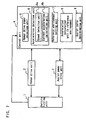
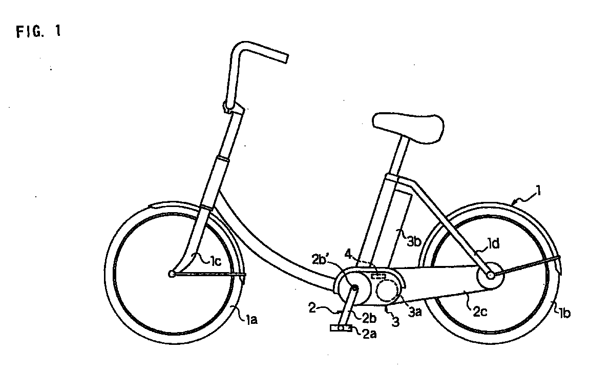
- FIG. 1 is an overall view showing a general configuration of a vehicle with power assist unit of a first embodiment of the present invention.
- FIG. 2 is a block diagram showing the configuration of the vehicle with power assist shown in FIG. 1.
- a vehicle with power assist unit of the present embodiment comprises a vehicle running unit 1 for running the vehicle, a human drive unit 2 and an assist power drive unit 3 for assistingly driving the vehicle running unit 1, and a control unit 4 for controlling the assist power drive unit 3.
- the vehicle running unit 1 is provided with wheels 1a and 1b rotatably making contact with a road surface to allow the vehicle to run, and support mechanisms 1c and 1d for rotatably supporting the wheels 1a and 1b, respectively.
- a human drive power from the human drive unit 2 and an assist power from the assist power drive unit 3 are supplied to the vehicle running unit 1.
- the wheels 1a and 1b are rotated by total powers, and the vehicle runs.
- the human drive unit 2 includes pedals 2a for receiving a human drive power from an operator or a user, and a transmission mechanism 2c comprising a pedal crank 2b, a chain, and a one-way clutch for transmitting the human drive power to the vehicle running unit 1 as the human drive force. Furthermore, the transmission mechanism 2c may be configured with use of a shaft drive.
- the assist power drive unit 3 includes a known drive unit 3a such as an actuator having an electric motor, and a battery 3b such as a secondary battery used as an electric power supply for the drive unit 3a.
- the drive unit 3a is activated (rotated) on the basis of an instruction signal from the control unit 4. Furthermore, output of the assist power drive unit 3 is transmitted as the assist power to the vehicle running unit 1 via the transmission mechanism 2c.
- a transmission mechanism for the assist power drive unit 3 is configured with a common mechanism for the human drive unit 2, and alternatively configured with an exclusive mechanism.
- the control unit 4 includes a human drive power detection unit 5 for detecting the human drive force Fh transmitted from the human drive unit 2 to the vehicle running unit 1.
- the control unit 4 further includes an acceleration detection unit 6 for detecting a current acceleration ⁇ 1 of the vehicle, and a reference environment setting unit 7 for presetting various references parameters in a reference environment described later.
- the control unit 4 includes an acceleration calculation unit 8 for calculating acceleration ⁇ o in the reference environment of the vehicle.
- the control unit 4 further includes an assist ratio determination unit 9 for determining a ratio Q (hereinafter referred to as an "assist ratio") of the assist power to the detected human drive force on the basis of the acceleration ⁇ o in the reference environment and the current acceleration ⁇ 1 .
- the human drive power detection unit 5 is formed of a torque sensor, and detects the human drive force Fh, which is proportional to the human drive power, in a predetermined time period (1 msec for example).
- the human drive power detection unit 5 outputs the detected human drive force Fh to the acceleration calculation unit 8 and the assist ratio determination unit 9.
- the torque sensor is herein defined as a non contact sensor which can detect the human drive force Fh transmitted from the human drive unit 2 to the vehicle running unit 1 as a torque without making connection to a member of the human drive unit 2, such as a crankshaft 2b', via a mechanical member or a wire, or without making sliding contact.
- a magnetic-distortion torque sensor comprising a belt-like magnetic film for generating a distortion in response to a change in the human drive force Fh applied to the pedal crank 2b and a coil for detecting a change in magnetic permeability due to the distortion is taken as an example of the non-contact torque sensor.
- another torque sensor is also available which comprises a spring disposed between the crankshaft 2b' and a drive sprocket (not shown), and detects a torque by detecting a strain generated in the spring by using an optical encoder or a Hall-effect device.
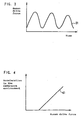
- the human drive force Fh detected by the human drive power detection unit 5 pulsates in response to the rotation of the pedal crank 2b as shown by a curve 31 shown in FIG. 3.
- the period of the pulsation is inversely proportional to the rotation speed of the pedal crank 2b. For this reason, when the pulsating human drive force Fh is used, the assist ratio is changed frequently, whereby the ride comfort of the vehicle may be lowered.
- the human drive power detection unit 5 calculates the average value of a plurality of continuously detected human drive force values, and outputs the average value to the acceleration calculation unit 8 and the assist ratio determination unit 9.
- the acceleration detection unit 6 comprises a speed detection unit 6a for detecting the current speed V of the vehicle, and an acceleration calculation unit 6b for calculating the current acceleration ⁇ 1 on the basis of the detected speed V.
- the speed detection unit 6a is formed of a mechanical-optical type or electromagnetic type encoder for example, and outputs the detected speed V to the acceleration calculation unit 6b and the acceleration calculation unit 8 in the reference environment.
- the acceleration detection unit 6 calculates the period of the human drive force Fh by using the human drive force Fh from the human drive power detection unit 5, and then calculates the speed V and the acceleration ⁇ 1 of the vehicle. With this configuration, no speed sensor is required to be used.
- the reference environment setting unit 7 is used to preset reference environment parameters required for calculating an acceleration in an estimated reference environment including road surface and meteorological conditions.
- Specific reference environment parameters are the inclination angle ⁇ of a road surface and running resistance d exerted on the vehicle.
- the running resistance d is stipulated in accordance with the above-mentioned inclination angle ⁇ , a kinetic friction force from the road surface, air resistance due to meteorological conditions such as wind, etc.
- the acceleration calculation unit 8 calculates acceleration ⁇ o in the reference environment when the vehicle runs therein. This calculation is carried out on the basis of the human drive force Fh from the human drive power detection unit 5, the speed V from the speed detection unit 6a and the reference environment parameters (the inclination angle ⁇ and the running resistance d) preset by the reference environment setting unit 7. More specifically, the acceleration calculation unit 8 calculates the above-mentioned acceleration ⁇ o by using the following equation of motion (1) for the vehicle, and outputs the acceleration ⁇ o to the assist ratio determination unit 9.
- m is the overall weight of the vehicle including the standard weight of the operator (60 kg for example), and g is the gravitational acceleration.
- the overall weight m and the gravitational acceleration g have been set beforehand in the acceleration calculation unit 8. Instead of use of the standard weight, it may be possible to use a detected weight of the operator with a load sensor.
- the second term on the right side of the equation (1) represents the assist power of the assist power drive unit 3. A predetermined initial value has been set as the assist ratio Q.
- the acceleration calculation unit 8 By substituting the reference environment parameters, the initial value of the assist ratio Q, the speed V and the human drive force Fh into the equation (1), the relationship between the acceleration ⁇ o and the human drive force Fh in the reference environment shown by a linear line 41 in FIG. 4 is obtained in the acceleration calculation unit 8 for example.
- the assist ratio determination unit 9 compares the current acceleration ⁇ 1 from the acceleration detection unit 6 with the acceleration ⁇ o in the reference environment from the acceleration calculation unit 8. In the case when the current acceleration ⁇ 1 is larger than the acceleration ⁇ o in the reference environment, that is, in the case where the current acceleration ⁇ 1 is located in an area above the linear line 41 shown in FIG. 4 she assist ratio determination unit 9 Judges that the initial value of the assist ratio Q is excessive for the current running environment. The assist ratio determination unit 9 then decreases the initial value of the assist ratio Q by a preset predetermined value. As a result, an instruction signal for decreasing the assist ratio Q is delivered from the control unit 4 to the assist power drive unit 3.
- the assist ratio determination unit 9 judges that the initial value of the assist ratio Q is insufficient for the current running environment.
- the assist ratio determination unit 9 then increases the initial value of the assist ratio Q by the preset predetermined value. As a result, an instruction signal for increasing the assist ratio Q is delivered from the control unit 4 to the assist power drive unit 3.
- the assist ratio determination unit 9 of the present embodiment can determine an assist ratio suited for a running environment responding with change of the running resistances. As a result, the vehicle can be driven appropriately.
- the assist ratio Q is zero in the case when the value of the human drive force supplied from the human drive power detection unit is zero. With this configuration, the vehicle can run safely. Furthermore, it may be possible to have a configuration wherein a sensor is provided to detect the operation angle of a brake lever operated by the operator, and the assist ratio determination unit 9 sets the assist ratio Q to zero when the operation angle becomes a predetermined angle or more.
- a running environment wherein the running resistance d is almost zero can be used as the reference environment.
- a value at the present time may be assigned to the assist ratio Q and substituted into the equation (1).
- the assist ratio Q may be calculated for each ratio.
- an alternative configuration may be such that various values say be calculated for each ratio responding with the ratio of the acceleration ⁇ o in the reference environment and the current acceleration ⁇ 1 .
- the preset predetermined value it may be possible to carry out a method wherein plural predetermined values may be ready for use, and may be selectively used appropriately.
- the equation (1) may be modified.
- a term proportional to the square of the speed may be added to the equation (1).
- an input device such as a numeric keypad may be provided so that the operator can change the overall weight m, the running resistance d or the inclination angle ⁇ .
- FIG. 5 is a flowchart showing the operation of the vehicle with power assist unit shown in FIG. 1.
- the human drive power detection unit 5 detects the human drive force transmitted from the human drive unit 2 to the vehicle running unit 1 in the first place (step S1). After this, the human drive power detection unit 5 outputs the detected human drive force to the acceleration calculation unit 8 in the reference environment and the assist ratio determination unit 9 (step S2).
- the acceleration calculation unit 8 calculates acceleration ⁇ o in the reference environment based upon the human drive force Fh from the human drive power detection unit 5, the speed V from the speed detection unit 6a and the preset reference environment parameters (the inclination angle ⁇ and the running resistance d) from the reference environment setting unit 7 (step S3). And then, the acceleration calculation unit 8 outputs the calculated acceleration ⁇ o in the reference environment to the assist ratio determination unit 9.
- the assist ratio determination unit 9 compares the current acceleration ⁇ 1 supplied from the acceleration detection unit 6 with the acceleration ⁇ o in the reference environment supplied from the acceleration calculation unit 8. The assist ratio determination unit 9 then determines whether the current acceleration ⁇ 1 is larger than the acceleration ⁇ o in the reference environment or not (step S4).
- the assist ratio determination unit 9 determines that the initial value of the assist ratio Q is excessive for the current running environment. After this, the assist ratio determination unit 9 decreases the initial value of the assist ratio Q by the preset predetermined value, and determines the obtained value as the assist ratio (step S5). As a result, an instruction signal for decreasing the assist ratio Q is delivered from the control unit 4 to the assist power drive unit 3.
- the assist ratio determination unit 9 judges that the initial value of the assist ratio Q is insufficient for the current running environment.
- the assist ratio determination unit 9 then increases the initial value of the assist ratio Q by the preset predetermined value (step S6). As a result, an instruction signal for increasing the assist ratio Q is delivered from the control unit 4 to the assist power drive unit 3.
- the acceleration calculation unit 8 in the reference environment calculates acceleration ⁇ o in the reference environment. This calculation is carried out on the basis of the human drive force Fh from the human drive power detection unit 5, the speed V from the speed detection unit 6a and the preset reference environment parameters from the reference environment setting unit 7. Furthermore, the assist ratio determination unit 9 compares the current acceleration ⁇ 1 supplied from the acceleration detection unit 6 with the acceleration ⁇ o in the reference environment supplied from the acceleration calculation unit 8, and determines the assist ratio Q on the basis of the result of the comparison.
- the vehicle with power assist unit and the controlling method for the same of the present embodiment it is possible to determine the assist ratio Q suited for the running environment responding with the change of the running resistances. As a result, the vehicle can be driven appropriately. Consequently, in the vehicle with power assist unit and the controlling method of the present embodiment, the vehicle can run naturally and smoothly without imposing any sense of discomfort on an operator or the like with respect to the ride comfort of the vehicle.
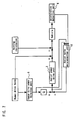
- FIG. 6 is a block diagram showing the configuration of a vehicle with power assist unit of a second embodiment of the present invention.
- an assist ratio determination unit estimates a current running environment on the basis of a detected human drive force and a detected acceleration, and determines an assist ratio. Except for this feature, the present embodiment is the same as the first embodiment, and descriptions overlapping each other are omitted.
- an assist ratio determination unit 11 in a control unit 10 estimates the current running environment on the basis of the human drive force Fh from the human drive power detection unit 5 and the acceleration ⁇ 1 from the acceleration detection unit 6, and determines the assist ratio.
- a method of determining the assist ratio by using the assist ratio determination unit 11 will be elucidated with reference to FIG. 6 and FIG. 7 more specifically.
- FIG. 7 is a block diagram showing a method of determining an assist ratio for the vehicle with power assist unit shown in FIG. 6.
- a force R in a running environment exerted on the running vehicle is represented by using a function having the speed V of the vehicle, running resistance d, the overall weight m of the vehicle, the gravitational acceleration g and the inclination angle ⁇ of a road surface as parameter thereof.
- the force R is represented by the following equation (2).
- the preset value including the initial value, the value at the present time or the value calculated responding with the detected current human drive force is used as the assist ratio Q in equation (3).
- the assist ratio determination unit 11 selects one of the preset value, the value at the present time and the value calculated responding with the detected current human drive force, and determines the selected value as a first assist ratio.
- a second assist ratio q is calculated by substituting the human drive force Fh from the human drive power detection unit 5 and the acceleration ⁇ 1 from the acceleration detection unit 6 into the above-mentioned equation (5).
- the assist ratio determination unit 11 determines this second assist ratio q as a new assist ratio. Consequently, it is possible to determine the assist ratio suited for the current running environment, and the vehicle can be driven appropriately.
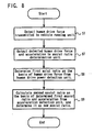
- FIG. 8 is a flowchart showing the operation of the vehicle with power assist unit shown in FIG. 6.
- the human drive power detection unit 5 outputs the detected human drive force
- the acceleration detection unit 6 outputs the detected acceleration to the assist ratio determination unit 11 (step S7).
- the assist ratio determination unit 11 selects one of the preset value including the initial value, the value at the present time and the value calculated responding with the detected current human drive force, and determines the selected value as the first assist ratio (step S8).
- the assist ratio determination unit 11 calculates the second assist ratio q, and determines the second assist ratio q as the new assist ratio Q (step S9).
- the assist ratio determination unit 11 estimates the current running environment on the basis of the human drive force Fh from the human drive power detection unit 5 and the acceleration ⁇ 1 from the acceleration detection unit 6, and determines the assist ratio. With this configuration of the vehicle with power assist unit and the controlling method for the same of the present embodiment, it is possible to determine the assist ratio suited for the running environment responding with the change of the running resistances. As a result, the vehicle can be driven appropriately.
- the vehicle with power assist unit and the controlling method for the same of the present embodiment it is possible to determine the assist ratio more suited for the current running environment than that in the case of the first embodiment wherein the preset inclination angle ⁇ and running resistance d are used as the reference environment parameters.
- FIG. 9 is a block diagram showing the configuration of a vehicle with power assist unit of a third embodiment of the present invention.
- an inclination angle detection unit is provided to detect the inclination angle of the road surface.
- An assist ratio determination unit estimates the current running environment on the basis of the detected human drive force, the detected acceleration and a detected inclination angle, and determines the assist ratio. Except for this feature, the present embodiment is the same as the second embodiment, and descriptions overlapping each other are omitted.
- an inclination angle detection unit 13 for detecting the inclination angle ⁇ of the road surface is provided in a control unit 12.
- An assist ratio determination unit 14 estimates a current running environment on the basis of a human drive force Fh from a human drive power detection unit 5, an acceleration ⁇ 1 from an acceleration detection unit 6 and an inclination angle ⁇ from the inclination angle detection unit 13, and determines an assist ratio.
- a force R' exerted on the running vehicle due to the running resistance d is represented by the following equation (7) by using the speed V of the vehicle and the running resistance d.
- the assist ratio q' is calculated by substituting the human drive force Fh from the human drive power detection unit 5, the acceleration ⁇ 1 from the acceleration detection unit 6 and the inclination angle ⁇ from the inclination angle detection unit 13 into the above-mentioned equation (10).
- the assist ratio determination unit 14 determines the assist ratio q' as a new assist ratio. Consequently, it is possible to determine an assist ratio suited for a current running environment, and the vehicle can be driven appropriately.
- FIG. 10 is a flowchart showing the operation of the vehicle with power assist unit shown in FIG. 9.
- the human drive power detection unit 5 outputs the detected human drive force
- the acceleration detection unit 6 outputs the detected acceleration
- the inclination angle detection unit 13 outputs the detected inclination angle to the assist ratio determination unit 14 (step S10).
- the assist ratio determination unit 14 selects one of the preset value including the initial value, the value at the present tile and the value calculated responding with the detected current human drive force, and determines the selected value as the first assist ratio (step S8). After this, on the basis of the determined first assist ratio, the acceleration ⁇ 1 from the acceleration detection unit 6 and the inclination angle ⁇ from the inclination angle detection unit 13, the assist ratio determination unit 14 calculates the second assist ratio q, and determines the second assist ratio q as the new assist ratio Q.
- the assist ratio determination unit 14 estimates the current running environment on the basis of the human drive force Fh from the human drive power detection unit 5, the acceleration ⁇ 1 from the acceleration detection unit 6 and the inclination angle ⁇ from the inclination angle detection unit 13, and determines the assist ratio.
- the assist ratio suited for the running environment responding with the change of the running resistances. As a result, the vehicle can be driven appropriately.
Landscapes
- Engineering & Computer Science (AREA)
- Chemical & Material Sciences (AREA)
- Combustion & Propulsion (AREA)
- Transportation (AREA)
- Mechanical Engineering (AREA)
- Electric Propulsion And Braking For Vehicles (AREA)
- Handcart (AREA)
- Steering Control In Accordance With Driving Conditions (AREA)
Abstract
Description
- The present invention relates to a vehicle with power assist unit which is driven by using human power and assist power from the power assist unit, and a controlling method for the same.
- Recently, a vehicle with power assist unit has been developed to include a known drive device, such as an electric motor, as a power assist unit, and driven by assist power from the power assist unit applied in addition to a force (hereinafter referred to as a "human drive power") based on human power by an operator, a user or the like. Specific examples of such vehicles are a bicycle with the motor, a wheelchair with the motor, a cargo carrier with the motor and the like. In this kind of vehicle, assist power generated by the motor is added over a rotation power generated by pressing pedals or a rotation power generated by rotating hand rims of wheels. This type of vehicle with power assist unit are driven by always adding the assist power to the human drive power with a certain ratio (hereinafter referred to as an "assist ratio").
- For example, a bicycle with electric motor has been disclosed in Japanese Laid-open Patent Application No. Hei 6-255564 as a first conventional vehicle with power assist unit. This first conventional vehicle with power assist unit is provided with a motor output calculation unit which measures human drive power in one period of motion cycle and then determines an average electric motor output (or an average torque) for the next period on the basis of the value of the measurement. The first conventional vehicle with power assist unit is also provided With an output control unit for generating the obtained motor output. In other words, in the first conventional vehicle with power assist unit, the output torque of the electric motor is controlled by responding in each period of a change in the detected human drive force, thereby to drive the vehicle.
- However, the first conventional vehicle with power assist unit is configured to add assist power having a constant assist ratio for the human drive power responding in each period of a change in the detected human drive power to the human drive power without regard for running resistances corresponding to road surface and meteorological conditions. For this reason, in the first conventional vehicle with power assist unit, it was impossible to drive its wheels appropriately responding with change of the running resistances.
- As a second conventional vehicle with power assist unit, an assist power control method for a power-assisted bicycle and an apparatus for the same have been disclosed in Japanese Laid-open Patent Application No. Hei 8-99683. This second conventional vehicle with power assist unit is provided with a speed sensor for detecting vehicle speed and a sensor for detecting acceleration of the vehicle and inclination angle of road surface. In the second conventional vehicle with power assist unit, the amount of work due to the bicycle is estimated on the basis of the detected speed and acceleration or inclination angle. With this configuration of the second conventional vehicle with power assist unit, the output torque of the electric motor is determined on the basis of the estimated human drive power without directly detecting the human drive power.
- However, in the second conventional vehicle with power assist unit, it was impossible to detect change of the running resistances. For this reason, just as in the case of the first conventional vehicle with power assist unit, the second conventional vehicle with power assist unit cannot appropriately drive its wheels responding with the change of the running resistances.
- As described above, in the conventional vehicles with power assist units, the assist ratio cannot be changed or determined to an optimal value in response to the change of the running resistances because the assist power is determined responding with the human drive power and the amount of work thereof. Therefore, an assist ratio suited for a running environment cannot be determined in the case of the conventional vehicles with power assist units, and an excessive burden or too much assist power were imposed on the operator or user. This results in lowering the ride comfort of the vehicle (bicycle) in the conventional vehicle with power assist unit.
- The object of the present invention is to provide a vehicle with power assist unit and controlling method for the same that can solve the aforementioned problems in the conventional vehicle with power assist unit and controlling method for the same, can be configured with less cost and has a long life.
- In order to achieve the above-mentioned object, a vehicle has power assist unit including a vehicle running unit for running the vehicle, a human drive unit for supplying a human drive power to the vehicle running unit and an assist power drive unit for supplying assist power to the vehicle running unit, and,
- the vehicle comprises:
- a human drive power detection unit for detecting a human drive force,
- an acceleration detection unit for detecting the speed and the acceleration of said vehicle,
- a reference environment setting unit for presetting various reference parameters in a reference environment wherein the vehicle runs,
- an acceleration calculation unit in the reference environment for calculating an acceleration in the reference environment in the case where the vehicle runs in the reference environment on the basis of the human drive force from the human drive power detection unit, the speed from the acceleration detection unit and the parameters in the reference environment from the reference environment setting unit, and
- an assist ratio determination unit for determining the assist ratio of the assist power drive unit to the human drive unit on the basis of the acceleration from the acceleration detection unit and said acceleration in the reference environment from the acceleration calculation unit.
-
- With this configuration of the vehicle with power assist unit of the present invention, it is possible to determine an assist ratio suited for a running environment responding with change of running resistances. As a result, the vehicle can be driven appropriately. Consequently, the vehicle can run naturally and smoothly without excessive burden and too much assist power on an operator or the like with respect to the ride comfort and performance of the vehicle.
-
- FIG. 1 is an overall view showing a general configuration of a vehicle with power assist unit of a first embodiment of the present invention.
- FIG. 2 is a block diagram showing the configuration of the vehicle with power assist unit shown in FIG. 1.
- FIG. 3 is a graph showing an example of a human drive force detected by a human drive power detection unit shown in FIG. 2.
- FIG. 4 is a graph showing a relationship between an acceleration and a human drive force obtained by an acceleration calculation unit in a reference environment shown in FIG. 1.
- FIG. 5 is a flowchart showing the operation of the vehicle with power assist unit shown in FIG. 1.
- FIG. 6 is a block diagram showing the configuration of a vehicle with power assist unit of a second embodiment of the present invention.
- FIG. 7 is a block diagram showing a method of determining an assist ratio for the vehicle with power assist unit shown in FIG. 6.
- FIG. 8 is a flowchart showing the operation of the vehicle with power assist unit shown in FIG. 6.
- FIG. 9 is a block diagram showing the configuration of a vehicle with power assist unit of a third embodiment of the present invention.
- FIG. 10 is a flowchart showing the operation of the vehicle with power assist unit shown in FIG. 9.
-
- Preferred embodiments of a vehicle with power assist unit and controlling method for the same of the present invention will be described with reference to the accompanying drawings. In the following descriptions, a bicycle driven by a leg power (a pedal pressing power) in combination with an assist power will be described as a preferred embodiment of the vehicle with the power assist unit of the present invention. A wheelchair is realized as the other embodiment.
- FIG. 1 is an overall view showing a general configuration of a vehicle with power assist unit of a first embodiment of the present invention. FIG. 2 is a block diagram showing the configuration of the vehicle with power assist shown in FIG. 1.
- As shown in FIGs. 1 and 2, a vehicle with power assist unit of the present embodiment comprises a
vehicle running unit 1 for running the vehicle, ahuman drive unit 2 and an assistpower drive unit 3 for assistingly driving thevehicle running unit 1, and acontrol unit 4 for controlling the assistpower drive unit 3. - The
vehicle running unit 1 is provided with wheels 1a and 1b rotatably making contact with a road surface to allow the vehicle to run, and support mechanisms 1c and 1d for rotatably supporting the wheels 1a and 1b, respectively. A human drive power from thehuman drive unit 2 and an assist power from the assistpower drive unit 3 are supplied to thevehicle running unit 1. As a result, the wheels 1a and 1b are rotated by total powers, and the vehicle runs. - The
human drive unit 2 includes pedals 2a for receiving a human drive power from an operator or a user, and atransmission mechanism 2c comprising apedal crank 2b, a chain, and a one-way clutch for transmitting the human drive power to thevehicle running unit 1 as the human drive force. Furthermore, thetransmission mechanism 2c may be configured with use of a shaft drive. - The assist
power drive unit 3 includes a known drive unit 3a such as an actuator having an electric motor, and abattery 3b such as a secondary battery used as an electric power supply for the drive unit 3a. The drive unit 3a is activated (rotated) on the basis of an instruction signal from thecontrol unit 4. Furthermore, output of the assistpower drive unit 3 is transmitted as the assist power to thevehicle running unit 1 via thetransmission mechanism 2c. A transmission mechanism for the assistpower drive unit 3 is configured with a common mechanism for thehuman drive unit 2, and alternatively configured with an exclusive mechanism. - The
control unit 4 includes a human drivepower detection unit 5 for detecting the human drive force Fh transmitted from thehuman drive unit 2 to thevehicle running unit 1. Thecontrol unit 4 further includes anacceleration detection unit 6 for detecting a current acceleration α1 of the vehicle, and a reference environment setting unit 7 for presetting various references parameters in a reference environment described later. In addition, thecontrol unit 4 includes an acceleration calculation unit 8 for calculating acceleration αo in the reference environment of the vehicle. Thecontrol unit 4 further includes an assistratio determination unit 9 for determining a ratio Q (hereinafter referred to as an "assist ratio") of the assist power to the detected human drive force on the basis of the acceleration αo in the reference environment and the current acceleration α1. - The human drive
power detection unit 5 is formed of a torque sensor, and detects the human drive force Fh, which is proportional to the human drive power, in a predetermined time period (1 msec for example). The human drivepower detection unit 5 outputs the detected human drive force Fh to the acceleration calculation unit 8 and the assistratio determination unit 9. The torque sensor is herein defined as a non contact sensor which can detect the human drive force Fh transmitted from thehuman drive unit 2 to thevehicle running unit 1 as a torque without making connection to a member of thehuman drive unit 2, such as acrankshaft 2b', via a mechanical member or a wire, or without making sliding contact. More specifically, a magnetic-distortion torque sensor comprising a belt-like magnetic film for generating a distortion in response to a change in the human drive force Fh applied to the pedal crank 2b and a coil for detecting a change in magnetic permeability due to the distortion is taken as an example of the non-contact torque sensor. Instead of the non-contact torque sensor, another torque sensor is also available which comprises a spring disposed between thecrankshaft 2b' and a drive sprocket (not shown), and detects a torque by detecting a strain generated in the spring by using an optical encoder or a Hall-effect device. - The human drive force Fh detected by the human drive
power detection unit 5 pulsates in response to the rotation of the pedal crank 2b as shown by acurve 31 shown in FIG. 3. The period of the pulsation is inversely proportional to the rotation speed of the pedal crank 2b. For this reason, when the pulsating human drive force Fh is used, the assist ratio is changed frequently, whereby the ride comfort of the vehicle may be lowered. To solve this problem, it may be possible to have a configuration wherein the human drivepower detection unit 5 calculates the average value of a plurality of continuously detected human drive force values, and outputs the average value to the acceleration calculation unit 8 and the assistratio determination unit 9. Furthermore, it may also be possible to have a configuration wherein the maximum value of the human drive force detected in one period is multiplied by a predetermined value (1/√2 for example) and output to the acceleration calculation unit 8 and the assistratio determination unit 9. With these configurations, the change in the assist ratio Q becomes smooth, and it is possible to prevent the ride comfort of the vehicle from being lowered. - The
acceleration detection unit 6 comprises aspeed detection unit 6a for detecting the current speed V of the vehicle, and anacceleration calculation unit 6b for calculating the current acceleration α1 on the basis of the detected speed V. Thespeed detection unit 6a is formed of a mechanical-optical type or electromagnetic type encoder for example, and outputs the detected speed V to theacceleration calculation unit 6b and the acceleration calculation unit 8 in the reference environment. - Instead of the configuration described above, it may be possible to have a configuration wherein the
acceleration detection unit 6 calculates the period of the human drive force Fh by using the human drive force Fh from the human drivepower detection unit 5, and then calculates the speed V and the acceleration α1 of the vehicle. With this configuration, no speed sensor is required to be used. - The reference environment setting unit 7 is used to preset reference environment parameters required for calculating an acceleration in an estimated reference environment including road surface and meteorological conditions. Specific reference environment parameters are the inclination angle of a road surface and running resistance d exerted on the vehicle. The running resistance d is stipulated in accordance with the above-mentioned inclination angle , a kinetic friction force from the road surface, air resistance due to meteorological conditions such as wind, etc.
- The acceleration calculation unit 8 calculates acceleration αo in the reference environment when the vehicle runs therein. This calculation is carried out on the basis of the human drive force Fh from the human drive
power detection unit 5, the speed V from thespeed detection unit 6a and the reference environment parameters (the inclination angle and the running resistance d) preset by the reference environment setting unit 7. More specifically, the acceleration calculation unit 8 calculates the above-mentioned acceleration αo by using the following equation of motion (1) for the vehicle, and outputs the acceleration αo to the assistratio determination unit 9.
- In the equation (1), m is the overall weight of the vehicle including the standard weight of the operator (60 kg for example), and g is the gravitational acceleration. The overall weight m and the gravitational acceleration g have been set beforehand in the acceleration calculation unit 8. Instead of use of the standard weight, it may be possible to use a detected weight of the operator with a load sensor. The second term on the right side of the equation (1) represents the assist power of the assist
power drive unit 3. A predetermined initial value has been set as the assist ratio Q. - By substituting the reference environment parameters, the initial value of the assist ratio Q, the speed V and the human drive force Fh into the equation (1), the relationship between the acceleration αo and the human drive force Fh in the reference environment shown by a
linear line 41 in FIG. 4 is obtained in the acceleration calculation unit 8 for example. - The assist
ratio determination unit 9 compares the current acceleration α1 from theacceleration detection unit 6 with the acceleration αo in the reference environment from the acceleration calculation unit 8. In the case when the current acceleration α1 is larger than the acceleration αo in the reference environment, that is, in the case where the current acceleration α1 is located in an area above thelinear line 41 shown in FIG. 4 she assistratio determination unit 9 Judges that the initial value of the assist ratio Q is excessive for the current running environment. The assistratio determination unit 9 then decreases the initial value of the assist ratio Q by a preset predetermined value. As a result, an instruction signal for decreasing the assist ratio Q is delivered from thecontrol unit 4 to the assistpower drive unit 3. - On the other hand, in the case when the current acceleration α1 is smaller than the acceleration αo in the reference environment, that is, in the case where the current acceleration α1 is located in an area below the
linear line 41 shown in FIG. 4, the assistratio determination unit 9 judges that the initial value of the assist ratio Q is insufficient for the current running environment. The assistratio determination unit 9 then increases the initial value of the assist ratio Q by the preset predetermined value. As a result, an instruction signal for increasing the assist ratio Q is delivered from thecontrol unit 4 to the assistpower drive unit 3. - As described above, the assist
ratio determination unit 9 of the present embodiment can determine an assist ratio suited for a running environment responding with change of the running resistances. As a result, the vehicle can be driven appropriately. - Instead of the above-mentioned configuration, it may be possible to have a configuration wherein the assist ratio Q is zero in the case when the value of the human drive force supplied from the human drive power detection unit is zero. With this configuration, the vehicle can run safely. Furthermore, it may be possible to have a configuration wherein a sensor is provided to detect the operation angle of a brake lever operated by the operator, and the assist
ratio determination unit 9 sets the assist ratio Q to zero when the operation angle becomes a predetermined angle or more. - By setting d = 0 in the above-mentioned equation (1), a running environment wherein the running resistance d is almost zero can be used as the reference environment. Furthermore, instead of the initial value, a value at the present time may be assigned to the assist ratio Q and substituted into the equation (1). Moreover, responding with a ratio between the acceleration αo in the reference environment and the current acceleration α1, the assist ratio Q may be calculated for each ratio. Besides, even when a value is preset, it may be possible to carry out a method wherein plural setting values other than the initial value may be ready for use as the assist ratio Q, and may be selectively used appropriately as necessary.
- Apart from the aforementioned explanation, wherein the assist ratio Q is changed by the preset predetermined value, an alternative configuration may be such that various values say be calculated for each ratio responding with the ratio of the acceleration αo in the reference environment and the current acceleration α1. In addition, even when the preset predetermined value is used, it may be possible to carry out a method wherein plural predetermined values may be ready for use, and may be selectively used appropriately.
- Furthermore, instead of using the equation of motion (1) for the vehicle, the equation (1) may be modified. For example, a term proportional to the square of the speed may be added to the equation (1). Moreover, it may be possible to have a configuration wherein an input device such as a numeric keypad may be provided so that the operator can change the overall weight m, the running resistance d or the inclination angle .
- Operation of the vehicle with power assist unit will be described below referring to FIG. 5.
- FIG. 5 is a flowchart showing the operation of the vehicle with power assist unit shown in FIG. 1.
- As shown in FIG. 5, in the vehicle with power assist unit of the present embodiment, the human drive
power detection unit 5 detects the human drive force transmitted from thehuman drive unit 2 to thevehicle running unit 1 in the first place (step S1). After this, the human drivepower detection unit 5 outputs the detected human drive force to the acceleration calculation unit 8 in the reference environment and the assist ratio determination unit 9 (step S2). - Next, the acceleration calculation unit 8 calculates acceleration αo in the reference environment based upon the human drive force Fh from the human drive
power detection unit 5, the speed V from thespeed detection unit 6a and the preset reference environment parameters (the inclination angle and the running resistance d) from the reference environment setting unit 7 (step S3). And then, the acceleration calculation unit 8 outputs the calculated acceleration αo in the reference environment to the assistratio determination unit 9. - The assist
ratio determination unit 9 compares the current acceleration α1 supplied from theacceleration detection unit 6 with the acceleration αo in the reference environment supplied from the acceleration calculation unit 8. The assistratio determination unit 9 then determines whether the current acceleration α1 is larger than the acceleration αo in the reference environment or not (step S4). - In the case when the current acceleration α1 is larger than the acceleration αo in the reference environment, the assist
ratio determination unit 9 determines that the initial value of the assist ratio Q is excessive for the current running environment. After this, the assistratio determination unit 9 decreases the initial value of the assist ratio Q by the preset predetermined value, and determines the obtained value as the assist ratio (step S5). As a result, an instruction signal for decreasing the assist ratio Q is delivered from thecontrol unit 4 to the assistpower drive unit 3. - In the case when the current acceleration α1 is smaller than the acceleration αo in the reference environment, the assist
ratio determination unit 9 judges that the initial value of the assist ratio Q is insufficient for the current running environment. The assistratio determination unit 9 then increases the initial value of the assist ratio Q by the preset predetermined value (step S6). As a result, an instruction signal for increasing the assist ratio Q is delivered from thecontrol unit 4 to the assistpower drive unit 3. - As described above, in the vehicle with power assist unit and the controlling method for the same of the present embodiment, the acceleration calculation unit 8 in the reference environment calculates acceleration αo in the reference environment. This calculation is carried out on the basis of the human drive force Fh from the human drive
power detection unit 5, the speed V from thespeed detection unit 6a and the preset reference environment parameters from the reference environment setting unit 7. Furthermore, the assistratio determination unit 9 compares the current acceleration α1 supplied from theacceleration detection unit 6 with the acceleration αo in the reference environment supplied from the acceleration calculation unit 8, and determines the assist ratio Q on the basis of the result of the comparison. Thereby, in the vehicle with power assist unit and the controlling method for the same of the present embodiment, it is possible to determine the assist ratio Q suited for the running environment responding with the change of the running resistances. As a result, the vehicle can be driven appropriately. Consequently, in the vehicle with power assist unit and the controlling method of the present embodiment, the vehicle can run naturally and smoothly without imposing any sense of discomfort on an operator or the like with respect to the ride comfort of the vehicle. - FIG. 6 is a block diagram showing the configuration of a vehicle with power assist unit of a second embodiment of the present invention. In the configuration of a vehicle with power assist unit of the present embodiment, an assist ratio determination unit estimates a current running environment on the basis of a detected human drive force and a detected acceleration, and determines an assist ratio. Except for this feature, the present embodiment is the same as the first embodiment, and descriptions overlapping each other are omitted.
- Referring to FIG. 6, in the vehicle with power assist unit of the present embodiment; an assist
ratio determination unit 11 in acontrol unit 10 estimates the current running environment on the basis of the human drive force Fh from the human drivepower detection unit 5 and the acceleration α1 from theacceleration detection unit 6, and determines the assist ratio. With this configuration of the vehicle with power assist unit of the present embodiment, it is possible to determine the assist ratio suited for the running environment responding with the change of the running resistances. As a result, the vehicle can be driven appropriately. - A method of determining the assist ratio by using the assist
ratio determination unit 11 will be elucidated with reference to FIG. 6 and FIG. 7 more specifically. - FIG. 7 is a block diagram showing a method of determining an assist ratio for the vehicle with power assist unit shown in FIG. 6.
- Referring to FIG. 6 and FIG. 7, a force R in a running environment exerted on the running vehicle is represented by using a function having the speed V of the vehicle, running resistance d, the overall weight m of the vehicle, the gravitational acceleration g and the inclination angle of a road surface as parameter thereof. For example, the force R is represented by the following equation (2).

- The following equation (3) can be obtained from the aforementioned equations (1) and (2).

- Just as in the case of the first embodiment, the preset value including the initial value, the value at the present time or the value calculated responding with the detected current human drive force is used as the assist ratio Q in equation (3). In other words, on the basis of the human drive force from the human drive
power detection unit 5, the assistratio determination unit 11 selects one of the preset value, the value at the present time and the value calculated responding with the detected current human drive force, and determines the selected value as a first assist ratio. - In addition, since the force R in the running environment is a force exerted on the running vehicle, the force becomes a multiple of the detected human drive force, and the following equation (4) is set up.

- The following equation (5) can be obtained from the above-mentioned equations (3) and (4).

- A second assist ratio q is calculated by substituting the human drive force Fh from the human drive
power detection unit 5 and the acceleration α1 from theacceleration detection unit 6 into the above-mentioned equation (5). The assistratio determination unit 11 determines this second assist ratio q as a new assist ratio. Consequently, it is possible to determine the assist ratio suited for the current running environment, and the vehicle can be driven appropriately. - Furthermore, it may be possible to have a configuration wherein the value q is calculated from the following equation (6) to compensate for the inertia term of the vehicle. With this configuration, an inertia force exerted on the vehicle can be reduced, and the riding comfort of the vehicle can be improved. In the equation (6), p is a constant value determined depending on the rated output of an electric motor.

- Operation of the vehicle with power assist unit of the present embodiment will be described below referring to FIG. 8.
- FIG. 8 is a flowchart showing the operation of the vehicle with power assist unit shown in FIG. 6.
- As shown in FIG. 8, the human drive
power detection unit 5 outputs the detected human drive force, and theacceleration detection unit 6 outputs the detected acceleration to the assist ratio determination unit 11 (step S7). - Next, on the basis of the human drive force from the human drive
power detection unit 5, the assistratio determination unit 11 selects one of the preset value including the initial value, the value at the present time and the value calculated responding with the detected current human drive force, and determines the selected value as the first assist ratio (step S8). After this, on the basis of the determined first assist ratio and the acceleration α1 from theacceleration detection unit 6, the assistratio determination unit 11 calculates the second assist ratio q, and determines the second assist ratio q as the new assist ratio Q (step S9). - As described above, in the vehicle with power assist unit and the controlling method for the same of the present embodiment, the assist
ratio determination unit 11 estimates the current running environment on the basis of the human drive force Fh from the human drivepower detection unit 5 and the acceleration α1 from theacceleration detection unit 6, and determines the assist ratio. With this configuration of the vehicle with power assist unit and the controlling method for the same of the present embodiment, it is possible to determine the assist ratio suited for the running environment responding with the change of the running resistances. As a result, the vehicle can be driven appropriately. Furthermore, in the vehicle with power assist unit and the controlling method for the same of the present embodiment, it is possible to determine the assist ratio more suited for the current running environment than that in the case of the first embodiment wherein the preset inclination angle and running resistance d are used as the reference environment parameters. - FIG. 9 is a block diagram showing the configuration of a vehicle with power assist unit of a third embodiment of the present invention. In the configuration of a vehicle with power assist unit of the present embodiment, an inclination angle detection unit is provided to detect the inclination angle of the road surface. An assist ratio determination unit estimates the current running environment on the basis of the detected human drive force, the detected acceleration and a detected inclination angle, and determines the assist ratio. Except for this feature, the present embodiment is the same as the second embodiment, and descriptions overlapping each other are omitted.
- Referring to FIG. 9, in the vehicle with power assist unit of the present embodiment, an inclination
angle detection unit 13 for detecting the inclination angle of the road surface is provided in acontrol unit 12. An assistratio determination unit 14 estimates a current running environment on the basis of a human drive force Fh from a human drivepower detection unit 5, an acceleration α1 from anacceleration detection unit 6 and an inclination angle from the inclinationangle detection unit 13, and determines an assist ratio. With this configuration of the vehicle with power assist unit of the present embodiment, it is possible to determine the assist ratio suited for the running environment responding with the change of the running resistances. As a result, the vehicle can he driven appropriately. - More specifically, a force R' exerted on the running vehicle due to the running resistance d is represented by the following equation (7) by using the speed V of the vehicle and the running resistance d.

- The following equation (8) can be obtained from the aforementioned equations (1) and (7).

- In addition, since the force R' due to the running resistances is the force exerted on the running vehicle, the force becomes a multiple of the detected human drive force, and the following equation (9) is set up.

- The following equation (10) can be obtained from the above-mentioned equations (8) and (9).

- The assist ratio q' is calculated by substituting the human drive force Fh from the human drive
power detection unit 5, the acceleration α1 from theacceleration detection unit 6 and the inclination angle from the inclinationangle detection unit 13 into the above-mentioned equation (10). The assistratio determination unit 14 determines the assist ratio q' as a new assist ratio. Consequently, it is possible to determine an assist ratio suited for a current running environment, and the vehicle can be driven appropriately. - Operation of the vehicle with power assist unit of the present embodiment will be described below referring to FIG. 10.
- FIG. 10 is a flowchart showing the operation of the vehicle with power assist unit shown in FIG. 9.
- As shown in FIG. 10, the human drive
power detection unit 5 outputs the detected human drive force, theacceleration detection unit 6 outputs the detected acceleration, and the inclinationangle detection unit 13 outputs the detected inclination angle to the assist ratio determination unit 14 (step S10). - Next, Just as in the case of the second embodiment, on the basis of the human drive force from the human drive
power detection unit 5, the assistratio determination unit 14 selects one of the preset value including the initial value, the value at the present tile and the value calculated responding with the detected current human drive force, and determines the selected value as the first assist ratio (step S8). After this, on the basis of the determined first assist ratio, the acceleration α1 from theacceleration detection unit 6 and the inclination angle from the inclinationangle detection unit 13, the assistratio determination unit 14 calculates the second assist ratio q, and determines the second assist ratio q as the new assist ratio Q. - As described above, in the vehicle with power assist unit and the controlling method for the same of the present embodiment, the assist
ratio determination unit 14 estimates the current running environment on the basis of the human drive force Fh from the human drivepower detection unit 5, the acceleration α1 from theacceleration detection unit 6 and the inclination angle from the inclinationangle detection unit 13, and determines the assist ratio. With this configuration of the vehicle with power assist unit and the controlling method for the same of the present embodiment, it is possible to determine the assist ratio suited for the running environment responding with the change of the running resistances. As a result, the vehicle can be driven appropriately. - Although the present invention has been described in terms of the presently preferred embodiments, it is to be understood that such disclosure is not to be interpreted as limiting. Various alterations and modifications will no doubt become apparent to those skilled in the art to which the present invention pertains, after having read the above disclosure. Accordingly, it is intended that the appended claims be interpreted as covering all alterations and modifications as fall within the true spirit and scope of the invention.
Claims (10)
- A vehicle with a power assist unit including a vehicle running unit for running said vehicle, a human drive unit for supplying a human drive power to said vehicle running unit and an assist power drive unit for supplying assist power to said vehicle running unit, comprising:a human drive power detection unit for detecting a human drive force,an acceleration detection unit for detecting the speed and the acceleration of said vehicle,a reference environment setting unit for presetting various reference parameters in a reference environment wherein said vehicle runs,an acceleration calculation unit in said reference environment for calculating an acceleration in said reference environment in the case where said vehicle runs in said reference environment on the basis of said human drive force from said human drive power detection unit, said speed from said acceleration detection unit and said parameters in said reference environment from said reference environment setting unit, andan assist ratio determination unit for determining the assist ratio of said assist power drive unit to said human drive unit on the basis of said acceleration from said acceleration detection unit and said acceleration in said reference environment from said acceleration calculation unit.
- A vehicle with a power assist unit in accordance with claim 1, wherein said acceleration calculation unit calculates said acceleration in said reference environment by using an equation of motion for said vehicle.
- A vehicle with a power assist unit in accordance with claim 2, wherein said equation of motion for said vehicle is represented by:wherein m is the overall weight of said vehicle, α is the acceleration of said vehicle, V is the speed of said vehicle, d is running resistances exerted on said vehicle, g is the gravitational acceleration exerted on said vehicle, is the inclination angle of a road surface on which said vehicle is running, Fh is a human drive force and Q is an assist ratio.

- A vehicle with a power assist unit including a vehicle running unit for running said vehicle, a human drive unit for supplying a human drive power to said vehicle running unit and an assist power drive unit for supplying assist power to said vehicle running unit, comprising:a human drive power detection unit for detecting a human drive force,an acceleration detection unit for detecting the acceleration of said vehicle, andan assist ratio determination unit for determining the assist ratio of said assist power drive unit to said human drive unit on the basis of said human drive force from said human drive power detection unit and said acceleration from said acceleration detection unit.
- A vehicle with a power assist unit including a vehicle running unit for running said vehicle, a human drive unit for supplying a human drive power to said vehicle running unit and on assist power drive unit for supplying assist power to said vehicle running unit, comprising:a human drive power detection unit for detecting a human drive force,an acceleration detection unit for detecting the acceleration of said vehicle,an inclination angle detection unit for detecting the inclination angle of a road surface on which said vehicle is running, andan assist ratio determination unit for determining the assist ratio of said assist power drive unit to said human drive unit on the basis of said human drive force from said human drive power detection unit, said acceleration from said acceleration detection unit and said inclination angle from said inclination angle detection unit.
- A method of controlling a vehicle with power assist unit including a vehicle running unit for running said vehicle, a human drive unit for supplying a human drive power to said vehicle running unit and an assist power drive unit for supplying assist power to said vehicle running unit, comprising:a detection step for detecting the speed and the acceleration of said vehicle, and a human drive force supplied to said vehicle running unit,an acceleration calculation step for calculating an acceleration in a reference environment in the case where said vehicle runs in said reference environment on the basis of said speed and said human drive force detected in said detection step, and preset various reference parameters for said reference environment, anda determination step for determining the assist ratio of said assist power drive unit to said human drive unit on the basis of said acceleration detected in said detection step and said acceleration in said reference environment calculated in said acceleration calculation step.
- A method of controlling a vehicle with power assist unit in accordance with claim 6, wherein said acceleration in said reference environment is calculated by using an equation of motion for said vehicle in said acceleration calculation step.
- A method of controlling a vehicle with power assist unit in accordance with claim 7, wherein said equation of motion for said vehicle is represented by:wherein m is the overall weight of said vehicle, α is the acceleration of said vehicle, V is the speed of said vehicle, d is running resistances exerted on said vehicle, g is the gravitational acceleration exerted on said vehicle, is the inclination angle of a road surface on which said vehicle is running, Fh is a human drive force, and Q is an assist ratio.

- A method of controlling a vehicle with power assist unit including a vehicle running unit for running said vehicle, a human drive unit for supplying a human drive power to said vehicle running unit and an assist power drive unit for supplying assist power to said vehicle running unit, comprising:a detection step for detecting the acceleration of said vehicle and a human drive force supplied to said vehicle running unit, anda determination step for determining the assist ratio of said assist power drive unit to said human drive unit on the basis of said acceleration and said human drive force detected in said detection step.
- A method of controlling a vehicle with power assist unit including a vehicle running unit for running said vehicle, a human drive unit for supplying a human drive power to said vehicle running unit and an assist power drive unit for supplying assist power to said vehicle running unit, comprising:a detection step for detecting the acceleration of said vehicle, a human drive force supplied to said vehicle running unit and the inclination angle of a road surface on which said vehicle is running, anda determination step for determining the assist ratio of said assist power drive unit to said human drive unit on the basis of said acceleration, said human drive force and said inclination angle detected in said detection step.
Applications Claiming Priority (4)
| Application Number | Priority Date | Filing Date | Title |
|---|---|---|---|
| JP35442997 | 1997-12-24 | ||
| JP35442997A JP3395619B2 (en) | 1997-12-24 | 1997-12-24 | Vehicle with auxiliary power unit |
| JP10147150A JPH11334676A (en) | 1998-05-28 | 1998-05-28 | Vehicle with auxiliary power unit and control method therefor |
| JP14715098 | 1998-05-28 |
Publications (4)
| Publication Number | Publication Date |
|---|---|
| EP0926059A2 true EP0926059A2 (en) | 1999-06-30 |
| EP0926059A3 EP0926059A3 (en) | 2001-03-21 |
| EP0926059B1 EP0926059B1 (en) | 2008-10-08 |
| EP0926059B8 EP0926059B8 (en) | 2008-12-24 |
Family
ID=26477789
Family Applications (1)
| Application Number | Title | Priority Date | Filing Date |
|---|---|---|---|
| EP19980310636 Expired - Lifetime EP0926059B8 (en) | 1997-12-24 | 1998-12-23 | Vehicle with power assist unit and controlling method therefor |
Country Status (3)
| Country | Link |
|---|---|
| EP (1) | EP0926059B8 (en) |
| DE (1) | DE69840090D1 (en) |
| TW (1) | TW387848B (en) |
Cited By (13)
| Publication number | Priority date | Publication date | Assignee | Title |
|---|---|---|---|---|
| EP1295785A1 (en) * | 2001-09-20 | 2003-03-26 | Berner Fachhochschule Hochschule für Technic und Architektur Biel | Vehicle |
| EP1129934A3 (en) * | 2000-03-01 | 2004-05-19 | Honda Giken Kogyo Kabushiki Kaisha | Motor-driven bicycle |
| US6957129B2 (en) | 2001-02-28 | 2005-10-18 | Honda Giken Kogyo Kabushiki Kaisha | Control unit for motor-assisted bicycle |
| DE102012201881A1 (en) * | 2012-02-09 | 2013-01-17 | Robert Bosch Gmbh | Control arrangement for electric bicycle, has acceleration sensor attached on electric bicycle for detecting acceleration of electric bicycle, where control unit is formed for releasing signals from acceleration sensor of electric motor |
| DE102011114337A1 (en) * | 2011-09-23 | 2013-03-28 | Bernd von Löbbecke | Motor control for an electric auxiliary drive |
| EP2860096A1 (en) * | 2013-10-10 | 2015-04-15 | Samsung Electro-Mechanics Co., Ltd. | Apparatus and method for controlling motor of electrical powered cycle |
| WO2015128239A1 (en) * | 2014-02-28 | 2015-09-03 | Commissariat A L'energie Atomique Et Aux Energies Alternatives | Assisting the movement of a wheel-mounted object by means of a control using the acceleration of the wheel-mounted object |
| DE102014219595A1 (en) * | 2014-09-26 | 2016-03-31 | Continental Teves Ag & Co. Ohg | Longitudinal dynamics control on the pedelec |
| EP3023326A1 (en) * | 2014-11-20 | 2016-05-25 | Mando Corporation | Electric bicycle and method of controlling the same |
| US9637197B2 (en) * | 2015-07-01 | 2017-05-02 | GM Global Technology Operations LLC | Dynamic inertia compensation and pedal effort transformation for electric bike |
| GB2557287A (en) * | 2016-12-05 | 2018-06-20 | Wen Sung Lee | Control device for an electric bicycle |
| CN108909931A (en) * | 2018-05-28 | 2018-11-30 | 纳恩博(北京)科技有限公司 | Power-assisted implementation method and device, the system of bicycle |
| JP2019166914A (en) * | 2018-03-22 | 2019-10-03 | 株式会社シマノ | Human-powered vehicular control device |
Families Citing this family (2)
| Publication number | Priority date | Publication date | Assignee | Title |
|---|---|---|---|---|
| DE102009028407A1 (en) * | 2009-08-10 | 2011-02-17 | Robert Bosch Gmbh | An energy management system for a combined electric and muscular powered vehicle and method of operating such a vehicle |
| EP3564111B1 (en) * | 2016-12-28 | 2024-07-10 | Yamaha Hatsudoki Kabushiki Kaisha | Electric assistance system and electrically assisted vehicle |
Citations (2)
| Publication number | Priority date | Publication date | Assignee | Title |
|---|---|---|---|---|
| JPH06255564A (en) | 1993-03-05 | 1994-09-13 | Moriyama Kogyo Kk | Bicycle with electric motor |
| JPH0899683A (en) | 1994-09-30 | 1996-04-16 | Suzuki Motor Corp | Method and device for controlling auxiliary power of power bicycle |
Family Cites Families (3)
| Publication number | Priority date | Publication date | Assignee | Title |
|---|---|---|---|---|
| IT1268881B1 (en) * | 1994-10-12 | 1997-03-13 | L Elettronica Ind E Navale S P | ELECTRIC MOTOR PROPULSION DEVICE, IN PARTICULAR IN VEHICLES WITH ONE, TWO OR MORE DRIVE WHEELS AND VEHICLE WITH SAID |
| JPH08258782A (en) * | 1995-03-27 | 1996-10-08 | Sanyo Electric Co Ltd | Motor-driven bicycle |
| DE19601194C2 (en) * | 1996-01-15 | 1997-11-27 | Michael Stamm | Method for controlling an auxiliary drive of a bicycle as a function of the torque delivered by a cyclist |
-
1998
- 1998-12-23 TW TW087121563A patent/TW387848B/en not_active IP Right Cessation
- 1998-12-23 DE DE69840090T patent/DE69840090D1/en not_active Expired - Lifetime
- 1998-12-23 EP EP19980310636 patent/EP0926059B8/en not_active Expired - Lifetime
Patent Citations (2)
| Publication number | Priority date | Publication date | Assignee | Title |
|---|---|---|---|---|
| JPH06255564A (en) | 1993-03-05 | 1994-09-13 | Moriyama Kogyo Kk | Bicycle with electric motor |
| JPH0899683A (en) | 1994-09-30 | 1996-04-16 | Suzuki Motor Corp | Method and device for controlling auxiliary power of power bicycle |
Cited By (16)
| Publication number | Priority date | Publication date | Assignee | Title |
|---|---|---|---|---|
| EP1129934A3 (en) * | 2000-03-01 | 2004-05-19 | Honda Giken Kogyo Kabushiki Kaisha | Motor-driven bicycle |
| US6957129B2 (en) | 2001-02-28 | 2005-10-18 | Honda Giken Kogyo Kabushiki Kaisha | Control unit for motor-assisted bicycle |
| EP1295785A1 (en) * | 2001-09-20 | 2003-03-26 | Berner Fachhochschule Hochschule für Technic und Architektur Biel | Vehicle |
| DE102011114337A1 (en) * | 2011-09-23 | 2013-03-28 | Bernd von Löbbecke | Motor control for an electric auxiliary drive |
| DE102012201881A1 (en) * | 2012-02-09 | 2013-01-17 | Robert Bosch Gmbh | Control arrangement for electric bicycle, has acceleration sensor attached on electric bicycle for detecting acceleration of electric bicycle, where control unit is formed for releasing signals from acceleration sensor of electric motor |
| EP2860096A1 (en) * | 2013-10-10 | 2015-04-15 | Samsung Electro-Mechanics Co., Ltd. | Apparatus and method for controlling motor of electrical powered cycle |
| WO2015128239A1 (en) * | 2014-02-28 | 2015-09-03 | Commissariat A L'energie Atomique Et Aux Energies Alternatives | Assisting the movement of a wheel-mounted object by means of a control using the acceleration of the wheel-mounted object |
| FR3018057A1 (en) * | 2014-02-28 | 2015-09-04 | Commissariat Energie Atomique | ASSISTING THE MOVEMENT OF A ROLLING OBJECT BY ASSERVING USING THE ACCELERATION OF THE ROLLING OBJECT |
| DE102014219595A1 (en) * | 2014-09-26 | 2016-03-31 | Continental Teves Ag & Co. Ohg | Longitudinal dynamics control on the pedelec |
| EP3023326A1 (en) * | 2014-11-20 | 2016-05-25 | Mando Corporation | Electric bicycle and method of controlling the same |
| US9545973B2 (en) | 2014-11-20 | 2017-01-17 | Mando Corporation | Electric bicycle and control method thereof |
| US9637197B2 (en) * | 2015-07-01 | 2017-05-02 | GM Global Technology Operations LLC | Dynamic inertia compensation and pedal effort transformation for electric bike |
| GB2557287A (en) * | 2016-12-05 | 2018-06-20 | Wen Sung Lee | Control device for an electric bicycle |
| JP2019166914A (en) * | 2018-03-22 | 2019-10-03 | 株式会社シマノ | Human-powered vehicular control device |
| CN108909931A (en) * | 2018-05-28 | 2018-11-30 | 纳恩博(北京)科技有限公司 | Power-assisted implementation method and device, the system of bicycle |
| CN108909931B (en) * | 2018-05-28 | 2021-01-05 | 纳恩博(北京)科技有限公司 | Method, device and system for realizing assistance of bicycle |
Also Published As
| Publication number | Publication date |
|---|---|
| TW387848B (en) | 2000-04-21 |
| EP0926059B1 (en) | 2008-10-08 |
| EP0926059B8 (en) | 2008-12-24 |
| EP0926059A3 (en) | 2001-03-21 |
| DE69840090D1 (en) | 2008-11-20 |
Similar Documents
| Publication | Publication Date | Title |
|---|---|---|
| EP0926059A2 (en) | Vehicle with power assist unit and controlling method therefor | |
| EP0798204B1 (en) | Regeneration control device for bicycle with auxiliary motor | |
| US5322352A (en) | Electric vehicle regenerative and friction braking control system | |
| EP1236640B1 (en) | Control unit for motor-assisted bicycle | |
| US5457363A (en) | Driving-force regulating apparatus for electric vehicle | |
| EP1886913B1 (en) | Electrically assisted bicycle | |
| EP0729881A1 (en) | Motorized bicycle | |
| EP0771721B1 (en) | Electrically assisted vehicle | |
| EP0825102A2 (en) | Torque limiting device for motors in electrically driven vehicles | |
| JP4608764B2 (en) | Control method for vehicle with auxiliary power unit | |
| JPH11105776A (en) | Electric assisted bicycle | |
| US6401019B2 (en) | Electric power steering apparatus | |
| EP0893338A1 (en) | Assist force control device in motor-assisted bicycle | |
| JP4744283B2 (en) | Vehicle with auxiliary power | |
| JPH08150982A (en) | Drive control device for electric bicycle | |
| JP2001080496A (en) | Electric brake device | |
| JP3105570B2 (en) | Manual drive with electric motor | |
| EP1188660B1 (en) | Assist power controller in motor assisted bicycle | |
| JP3054268B2 (en) | Bicycle with electric motor | |
| JPH07143603A (en) | Power assisted bicycle | |
| JP3974979B2 (en) | Auxiliary power control device for battery-assisted bicycle | |
| JP4183791B2 (en) | Vehicle with auxiliary power unit | |
| JPH08207876A (en) | Human powered vehicle with auxiliary drive source | |
| JPH11334676A (en) | Vehicle with auxiliary power unit and control method therefor | |
| KR100254427B1 (en) | Regenerative braking control device and method for electric vehicle |
Legal Events
| Date | Code | Title | Description |
|---|---|---|---|
| PUAI | Public reference made under article 153(3) epc to a published international application that has entered the european phase |
Free format text: ORIGINAL CODE: 0009012 |
|
| 17P | Request for examination filed |
Effective date: 19990121 |
|
| AK | Designated contracting states |
Kind code of ref document: A2 Designated state(s): DE FR NL |
|
| AX | Request for extension of the european patent |
Free format text: AL;LT;LV;MK;RO;SI |
|
| PUAL | Search report despatched |
Free format text: ORIGINAL CODE: 0009013 |
|
| AK | Designated contracting states |
Kind code of ref document: A3 Designated state(s): AT BE CH CY DE DK ES FI FR GB GR IE IT LI LU MC NL PT SE |
|
| AX | Request for extension of the european patent |
Free format text: AL;LT;LV;MK;RO;SI |
|
| AKX | Designation fees paid |
Free format text: DE FR NL |
|
| RAP1 | Party data changed (applicant data changed or rights of an application transferred) |
Owner name: KOSUGE, KAZUHIRO Owner name: MATSUSHITA ELECTRIC INDUSTRIAL CO., LTD. |
|
| 17Q | First examination report despatched |
Effective date: 20060705 |
|
| 17Q | First examination report despatched |
Effective date: 20060705 |
|
| GRAP | Despatch of communication of intention to grant a patent |
Free format text: ORIGINAL CODE: EPIDOSNIGR1 |
|
| RAP1 | Party data changed (applicant data changed or rights of an application transferred) |
Owner name: KOSUGE, KAZUHIRO Owner name: MATSUSHITA ELECTRIC INDUSTRIAL CO., LTD |
|
| GRAS | Grant fee paid |
Free format text: ORIGINAL CODE: EPIDOSNIGR3 |
|
| GRAA | (expected) grant |
Free format text: ORIGINAL CODE: 0009210 |
|
| AK | Designated contracting states |
Kind code of ref document: B1 Designated state(s): DE FR NL |
|
| RAP2 | Party data changed (patent owner data changed or rights of a patent transferred) |
Owner name: KOSUGE, KAZUHIRO Owner name: PANASONIC CORPORATION |
|
| REF | Corresponds to: |
Ref document number: 69840090 Country of ref document: DE Date of ref document: 20081120 Kind code of ref document: P |
|
| NLT2 | Nl: modifications (of names), taken from the european patent patent bulletin |
Owner name: PANASONIC CORPORATION EN KOSUGE, KAZUHIRO Effective date: 20081119 |
|
| PLBE | No opposition filed within time limit |
Free format text: ORIGINAL CODE: 0009261 |
|
| STAA | Information on the status of an ep patent application or granted ep patent |
Free format text: STATUS: NO OPPOSITION FILED WITHIN TIME LIMIT |
|
| 26N | No opposition filed |
Effective date: 20090709 |
|
| PGFP | Annual fee paid to national office [announced via postgrant information from national office to epo] |
Ref country code: FR Payment date: 20130107 Year of fee payment: 15 Ref country code: NL Payment date: 20121215 Year of fee payment: 15 |
|
| REG | Reference to a national code |
Ref country code: NL Ref legal event code: V1 Effective date: 20140701 |
|
| REG | Reference to a national code |
Ref country code: FR Ref legal event code: ST Effective date: 20140829 |
|
| PG25 | Lapsed in a contracting state [announced via postgrant information from national office to epo] |
Ref country code: NL Free format text: LAPSE BECAUSE OF NON-PAYMENT OF DUE FEES Effective date: 20140701 |
|
| PG25 | Lapsed in a contracting state [announced via postgrant information from national office to epo] |
Ref country code: FR Free format text: LAPSE BECAUSE OF NON-PAYMENT OF DUE FEES Effective date: 20131231 |
|
| PGFP | Annual fee paid to national office [announced via postgrant information from national office to epo] |
Ref country code: DE Payment date: 20171220 Year of fee payment: 20 |
|
| REG | Reference to a national code |
Ref country code: DE Ref legal event code: R071 Ref document number: 69840090 Country of ref document: DE |