EP3564103A1 - Balance scooter startup method and apparatus controlling balance scooter startup - Google Patents
Balance scooter startup method and apparatus controlling balance scooter startup Download PDFInfo
- Publication number
- EP3564103A1 EP3564103A1 EP17886304.9A EP17886304A EP3564103A1 EP 3564103 A1 EP3564103 A1 EP 3564103A1 EP 17886304 A EP17886304 A EP 17886304A EP 3564103 A1 EP3564103 A1 EP 3564103A1
- Authority
- EP
- European Patent Office
- Prior art keywords
- power supply
- balance scooter
- startup
- module
- electrical signal
- Prior art date
- Legal status (The legal status is an assumption and is not a legal conclusion. Google has not performed a legal analysis and makes no representation as to the accuracy of the status listed.)
- Withdrawn
Links
Images

Classifications
-
- B—PERFORMING OPERATIONS; TRANSPORTING
- B60—VEHICLES IN GENERAL
- B60L—PROPULSION OF ELECTRICALLY-PROPELLED VEHICLES; SUPPLYING ELECTRIC POWER FOR AUXILIARY EQUIPMENT OF ELECTRICALLY-PROPELLED VEHICLES; ELECTRODYNAMIC BRAKE SYSTEMS FOR VEHICLES IN GENERAL; MAGNETIC SUSPENSION OR LEVITATION FOR VEHICLES; MONITORING OPERATING VARIABLES OF ELECTRICALLY-PROPELLED VEHICLES; ELECTRIC SAFETY DEVICES FOR ELECTRICALLY-PROPELLED VEHICLES
- B60L15/00—Methods, circuits, or devices for controlling the traction-motor speed of electrically-propelled vehicles
- B60L15/20—Methods, circuits, or devices for controlling the traction-motor speed of electrically-propelled vehicles for control of the vehicle or its driving motor to achieve a desired performance, e.g. speed, torque, programmed variation of speed
-
- B—PERFORMING OPERATIONS; TRANSPORTING
- B62—LAND VEHICLES FOR TRAVELLING OTHERWISE THAN ON RAILS
- B62K—CYCLES; CYCLE FRAMES; CYCLE STEERING DEVICES; RIDER-OPERATED TERMINAL CONTROLS SPECIALLY ADAPTED FOR CYCLES; CYCLE AXLE SUSPENSIONS; CYCLE SIDECARS, FORECARS, OR THE LIKE
- B62K11/00—Motorcycles, engine-assisted cycles or motor scooters with one or two wheels
- B62K11/007—Automatic balancing machines with single main ground engaging wheel or coaxial wheels supporting a rider
-
- B—PERFORMING OPERATIONS; TRANSPORTING
- B60—VEHICLES IN GENERAL
- B60L—PROPULSION OF ELECTRICALLY-PROPELLED VEHICLES; SUPPLYING ELECTRIC POWER FOR AUXILIARY EQUIPMENT OF ELECTRICALLY-PROPELLED VEHICLES; ELECTRODYNAMIC BRAKE SYSTEMS FOR VEHICLES IN GENERAL; MAGNETIC SUSPENSION OR LEVITATION FOR VEHICLES; MONITORING OPERATING VARIABLES OF ELECTRICALLY-PROPELLED VEHICLES; ELECTRIC SAFETY DEVICES FOR ELECTRICALLY-PROPELLED VEHICLES
- B60L2200/00—Type of vehicles
- B60L2200/24—Personal mobility vehicles
-
- B—PERFORMING OPERATIONS; TRANSPORTING
- B62—LAND VEHICLES FOR TRAVELLING OTHERWISE THAN ON RAILS
- B62K—CYCLES; CYCLE FRAMES; CYCLE STEERING DEVICES; RIDER-OPERATED TERMINAL CONTROLS SPECIALLY ADAPTED FOR CYCLES; CYCLE AXLE SUSPENSIONS; CYCLE SIDECARS, FORECARS, OR THE LIKE
- B62K2202/00—Motorised scooters
-
- Y—GENERAL TAGGING OF NEW TECHNOLOGICAL DEVELOPMENTS; GENERAL TAGGING OF CROSS-SECTIONAL TECHNOLOGIES SPANNING OVER SEVERAL SECTIONS OF THE IPC; TECHNICAL SUBJECTS COVERED BY FORMER USPC CROSS-REFERENCE ART COLLECTIONS [XRACs] AND DIGESTS
- Y02—TECHNOLOGIES OR APPLICATIONS FOR MITIGATION OR ADAPTATION AGAINST CLIMATE CHANGE
- Y02T—CLIMATE CHANGE MITIGATION TECHNOLOGIES RELATED TO TRANSPORTATION
- Y02T10/00—Road transport of goods or passengers
- Y02T10/60—Other road transportation technologies with climate change mitigation effect
- Y02T10/72—Electric energy management in electromobility
Definitions
- the present disclosure relates to the field of balance scooter technologies, and specifically to a balance scooter startup method and an apparatus controlling balance scooter startup.
- an in-wheel motor disposed in wheels drive the wheels to rotate.
- startup of a balance scooter is performed by a physical switch, and in this manner of startup, an operator needs to press a startup key with a hand to make the balance scooter powered on and start up. Because the balance scooter is relatively short and is close to the ground, an operator usually needs to bend down to press the startup key, to make the balance scooter powered on to work. The operation of the startup process is inconvenient, affecting use enthusiasm of users.
- the technical problem to be solved by the present disclosure is to provide a balance scooter startup method, used to detect rocking motion of the balance scooter, rocking of wheels drives the electric motor to generate electricity, and collection of the electrical signal generated by the electric motor controls the balance scooter to automatically start up; the present disclosure is convenient for a user to employ, and improves a usage experience for a user.
- a balance scooter startup method including the following steps:
- the electrical signal triggering the power supply module of the control board to start is specifically:
- the converting the electrical signal into a power supply enable trigger signal includes: disposing a time delay module between the electrical signal and the power supply module.
- the time delay module is an RC time delay circuit.
- a resistor for a capacitor of the RC time delay circuit to discharge is disposed between the RC time delay circuit and the power supply module.
- the converting the electrical signal into a power supply enable trigger signal includes: connecting a diode in series between the electrical signal and the power supply module to prevent a reverse current.
- An apparatus controlling balance scooter startup including:
- the apparatus further includes a power supply enable trigger module, converting the electrical signal into a power supply enable trigger signal.
- the power supply enable trigger module includes a time delay module.
- the time delay module is an RC time delay circuit.
- the RC time delay circuit further includes a resistor disposed between the RC time delay circuit and the power supply module, for a capacitor of the RC time delay circuit to discharge.
- the apparatus further includes a diode connected in series between the electrical signal and the power supply module to prevent reverse current.
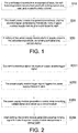
- Fig. 1 is a flowchart of steps of a balance scooter startup method according to an embodiment of the present disclosure, including the following steps: S10: For a balance scooter in a powered-off state, sense back and forth rocking motion of a user, and rotating an electric motor to generate electricity, and outputting an electrical signal.
- the back and forth rocking of the balance scooter makes the wheels rotate, to drive the electric motor connected to the wheels to rotate, and rotates the electric motor to generate electricity to generate an electrical signal.
- the electrical signal triggers the power supply module of the control board to start.
- the electrical signal generated by rotation of the electric motor By using the electrical signal generated by rotation of the electric motor to trigger the power supply module of the control board to start, the electrical signal generated by a rotate-to-generate-electricity attribute of the electric motor is effectively used to trigger the power supply module to enter a working state.
- the electrical signal triggering the power supply module of the control board to start may include the following steps.
- S201 Convert the electrical signal into a power supply enable trigger signal.
- the power supply enable trigger signal triggers the power supply module to start.
- the power supply module generates a control module working voltage signal and wakes up a control module.
- control module After the control module starts, the control module generates a startup holding signal to make the power supply module always keeping an on state.
- the working process is as follows.
- a user that prepares to ride the balance scooter steps on the balance scooter by one foot, and rocks the balance scooter back and forth by the foot, so that the wheels of the balance scooter (with the electric motor) rotate.
- the present disclosure is not limited to the form of stepping on the balance scooter by one foot. Stepping on the balance scooter by one foot to rock is also to make the wheels of the balance scooter to rotate, to drive the electric motor to rotate. Wheel rotation in other forms to make the electric motor generating electricity should also fall within the protection scope of the present disclosure.
- the power supply module is triggered and is started by the electrical signal generated by electricity generated by the rotary electric motor.
- a battery voltage V+ of the power supply module is converted into a working voltage VCC of the MCU of the control board, and the control board of the balance scooter starts to enter a running state from a powered off state.
- the MCU of the control board of the balance scooter in the running state generates a startup holding signal POWER ON for feedback to the power supply module, so that the power supply module always keeps startup and the battery supplies power to it; in this case, the balance scooter is started and startup is completed.
- a time delay module is disposed between the electrical signal generated by the electric motor and the power supply module.
- the time delay module is an RC time delay circuit, consisting of R1 and C1.
- a resistor R2 for a capacitor to discharge is disposed between the RC time delay circuit and the power supply module, and the resistor R2 is connected in parallel to C1.
- a diode D1 that prevents reverse current is connected in series between the electrical signal generated by the electric motor and the power supply module.
- the electrical signal of electricity generated by the electric motor triggers the enable signal of the power supply module, to drive an MCU of the control board to generate the startup holding signal to make the power supply module always keep an on state.
- the balance scooter starts to power the battery module, to complete the startup motion.
- the startup process of the balance scooter is easy and is convenient for a user to use.
- By disposing the time delay module between the electrical signal generated by the electric motor and the power supply module a balance scooter mistaken startup operation caused by a misoperation of an external force within short time is effectively avoided.
- the resistor for the capacitor of the time delay circuit to discharge between the time delay module and the power supply module, the mistaken startup operation when the balance scooter slightly shocks is avoided.
- the diode that prevents reverse current a false motion of the current of the startup holding signal of the power supply module for an electric motor coil is avoided, to effectively protect the electric motor and the power supply module.
- FIG. 3 another embodiment of the present disclosure provides an apparatus controlling balance scooter startup, including:
- an apparatus controlling balance scooter startup of this embodiment of the present disclosure further includes a power supply enable trigger module 104, converting the electrical signal into the power supply enable trigger signal EN.
- the working process is as follows. For example, a user that prepares to ride the balance scooter steps on the balance scooter by one foot, and rocks the balance scooter back and forth by using one foot, so that the wheels of the balance scooter (with the electric motor) rotate.
- the present disclosure is not limited to the form of stepping on the balance scooter by one foot. Stepping on the balance scooter by one foot to rock is also to make the wheels of the balance scooter rotate, provided that the electric motor is driven to rotate, and wheel rotation in other forms to make the electric motor generate electricity should also fall within the protection scope of the present disclosure.
- the electrical signal V MOTOR generated by electricity generated by the rotary electric motor is used to trigger startup of the power supply module, and after startup of the power supply module is triggered, a battery voltage V+ of the power supply module is converted into a working voltage VCC of the MCU of the control board, and the control board of the balance scooter starts to enter a running state from a powered off state; the MCU of the control board of the balance scooter in the running state generates a startup holding signal POWER_ON for feedback to the power supply module, so that the power supply module always keeps startup and the battery supplies power to the whole scooter; in this case, startup is completed.
- the power supply module and the control module may be both used as main modules through an integrated chip, and there is a plurality of types of integrated chips that can implement the function of the present disclosure.
- the power supply enable trigger module includes a time delay module.
- the time delay module is an RC time delay circuit, and consists of a first resistor R1 and a first capacitor C1 connected in parallel, to avoid a balance scooter mistaken startup operation caused by a misoperation of an external force within short time (for example, in a powered-off state, the misoperation of an external force causes fierce rocking, collision, vibration, slight movement, and other misoperations for a single time).
- a second resistor R2 connected in parallel to the first capacitor is further included, and is disposed between the RC time delay circuit and the power supply module, for the capacitor C 1 of the RC time delay circuit to discharge, to avoid a balance scooter mistaken startup operation caused by mistaken startup operation (for example, an infant slightly rocks the balance scooter with small force due to curiosity) when the balance scooter slightly rocks.
- a diode D1 is further included and is connected in series between the electrical signal and the power supply module, to prevent reverse current, and avoid a false motion of the current of the startup holding signal of the power supply module for an electric motor coil, to effectively protect the electric motor and the power supply module.
Landscapes
- Engineering & Computer Science (AREA)
- Mechanical Engineering (AREA)
- Power Engineering (AREA)
- Transportation (AREA)
- Motorcycle And Bicycle Frame (AREA)
- Electric Propulsion And Braking For Vehicles (AREA)
Abstract
Description
- The present disclosure relates to the field of balance scooter technologies, and specifically to a balance scooter startup method and an apparatus controlling balance scooter startup.
- In a driving process of an existing balance scooter, an in-wheel motor disposed in wheels drive the wheels to rotate. In addition, startup of a balance scooter is performed by a physical switch, and in this manner of startup, an operator needs to press a startup key with a hand to make the balance scooter powered on and start up. Because the balance scooter is relatively short and is close to the ground, an operator usually needs to bend down to press the startup key, to make the balance scooter powered on to work. The operation of the startup process is inconvenient, affecting use enthusiasm of users.
- The technical problem to be solved by the present disclosure is to provide a balance scooter startup method, used to detect rocking motion of the balance scooter, rocking of wheels drives the electric motor to generate electricity, and collection of the electrical signal generated by the electric motor controls the balance scooter to automatically start up; the present disclosure is convenient for a user to employ, and improves a usage experience for a user.
- To resolve the foregoing technical problem, the present disclosure uses the following technical solution:
- A balance scooter startup method, including the following steps:
- for a balance scooter in a powered-off state, sensing back and forth rocking motion of a user, and rotating an electric motor to generate electricity, and outputting an electrical signal;
- the electrical signal triggering the power supply module of the control board to start; and
- a battery of the power supply module starting to power the balance scooter, completing the balance scooter startup.
- As further improvement of the present disclosure, the electrical signal triggering the power supply module of the control board to start is specifically:
- converting the electrical signal into a power supply enabling trigger signal;
- the power supply enable trigger signal triggering the power supply module to start;
- the power supply module generating a control module working voltage signal and waking up a control module; and
- after the control module starts, generating a startup holding signal to make the power supply module always keeping an on state.
- As further improvement of the present disclosure, the converting the electrical signal into a power supply enable trigger signal includes: disposing a time delay module between the electrical signal and the power supply module.
- As further improvement of the present disclosure, the time delay module is an RC time delay circuit.
- As further improvement of the present disclosure, a resistor for a capacitor of the RC time delay circuit to discharge is disposed between the RC time delay circuit and the power supply module.
- As further improvement of the present disclosure, the converting the electrical signal into a power supply enable trigger signal includes: connecting a diode in series between the electrical signal and the power supply module to prevent a reverse current.
- The present disclosure further provides the following technical solution:
- An apparatus controlling balance scooter startup, including:
- a sensing electricity generation module, for a balance scooter in a powered-off state, sensing back and forth rocking motion of a user, and rotating an electric motor to generate electricity, and outputting an electrical signal;
- a power supply module, receiving the electrical signal and outputting a control module working voltage signal; and
- a control module, receiving the control module working voltage signal and being started, generating a startup holding signal to the power supply module, where a battery of the power supply module starts to power the balance scooter, completing the balance scooter startup.
- As further improvement of the present disclosure, the apparatus further includes a power supply enable trigger module, converting the electrical signal into a power supply enable trigger signal.
- As further improvement of the present disclosure, the power supply enable trigger module includes a time delay module.
- As further improvement of the present disclosure, the time delay module is an RC time delay circuit.
- As further improvement of the present disclosure, the RC time delay circuit further includes a resistor disposed between the RC time delay circuit and the power supply module, for a capacitor of the RC time delay circuit to discharge.
- As further improvement of the present disclosure, the apparatus further includes a diode connected in series between the electrical signal and the power supply module to prevent reverse current.
- The present disclosure has the following beneficial effects:
- 1. By rocking of the wheels to drive the electric motor to generate electricity, the electrical signal of electricity generated by the electric motor further generates the power supply enable trigger signal that triggers the power supply module, so that the control module generates the startup holding signal to make the power supply module always keep an on state, power of the balance scooter starts to be supplied by the battery module, and complete the startup motion. The startup process of the balance scooter implemented in the foregoing manner is easy and is convenient for a user to employ.
- 2. By disposing the time delay module between the electrical signal generated by the electric motor and the power supply module, a balance scooter mistaken startup operation caused by rotation of the wheels of the balance scooter driven by an external force within short time is effectively avoided.
- 3. The resistor for the capacitor of the time delay circuit to discharge is disposed between the time delay module and the power supply module, to avoid a mistaken startup operation when the balance scooter slightly shocks.
- 4. By disposing the diode that prevents reverse current, a false motion of the current of the startup holding signal of the power supply module for an electric motor coil is avoided, to effectively protect the electric motor and the power supply module.
-
-
Fig. 1 is a flowchart of steps of a balance scooter startup method according to an embodiment of the present disclosure. -
Fig. 2 is a flowchart of steps of triggering an electrical signal of a balance scooter startup method according to an embodiment of the present disclosure. -
Fig. 3 is a principle block diagram of an apparatus controlling balance scooter startup according to an embodiment of the present disclosure. -
Fig. 4 is a schematic structural diagram of an apparatus controlling balance scooter startup according to an embodiment of the present disclosure. - The following clearly and completely describes the technical solutions in the embodiments of the present disclosure with reference to the accompanying drawings in the embodiments of the present disclosure. Obviously, the described embodiments are only some embodiments instead of all embodiments of the present disclosure. All other embodiments obtained by a person of ordinary skill in the art according to the embodiments of the present disclosure without creative efforts shall fall within the protection scope of the present disclosure.
-
Fig. 1 is a flowchart of steps of a balance scooter startup method according to an embodiment of the present disclosure, including the following steps:
S10: For a balance scooter in a powered-off state, sense back and forth rocking motion of a user, and rotating an electric motor to generate electricity, and outputting an electrical signal. - If a user wants to use the balance scooter in a powered-off state, by rocking the balance scooter back and forth, the back and forth rocking of the balance scooter makes the wheels rotate, to drive the electric motor connected to the wheels to rotate, and rotates the electric motor to generate electricity to generate an electrical signal.
- S20: The electrical signal triggers the power supply module of the control board to start. By using the electrical signal generated by rotation of the electric motor to trigger the power supply module of the control board to start, the electrical signal generated by a rotate-to-generate-electricity attribute of the electric motor is effectively used to trigger the power supply module to enter a working state.
- In an exemplary embodiment, referring to
Fig. 2 , the electrical signal triggering the power supply module of the control board to start may include the following steps. - S201: Convert the electrical signal into a power supply enable trigger signal.
- S202: The power supply enable trigger signal triggers the power supply module to start.
- S203: The power supply module generates a control module working voltage signal and wakes up a control module.
- S204: After the control module starts, the control module generates a startup holding signal to make the power supply module always keeping an on state.
- S30: A battery of the power supply module starts to power the balance scooter, completing the balance scooter startup.
- According to the foregoing set balance scooter startup method, the working process is as follows. For example, a user that prepares to ride the balance scooter steps on the balance scooter by one foot, and rocks the balance scooter back and forth by the foot, so that the wheels of the balance scooter (with the electric motor) rotate. Certainly, the present disclosure is not limited to the form of stepping on the balance scooter by one foot. Stepping on the balance scooter by one foot to rock is also to make the wheels of the balance scooter to rotate, to drive the electric motor to rotate. Wheel rotation in other forms to make the electric motor generating electricity should also fall within the protection scope of the present disclosure. The power supply module is triggered and is started by the electrical signal generated by electricity generated by the rotary electric motor. After startup of the power supply module is triggered, a battery voltage V+ of the power supply module is converted into a working voltage VCC of the MCU of the control board, and the control board of the balance scooter starts to enter a running state from a powered off state. The MCU of the control board of the balance scooter in the running state generates a startup holding signal POWER ON for feedback to the power supply module, so that the power supply module always keeps startup and the battery supplies power to it; in this case, the balance scooter is started and startup is completed.
- In an embodiment, to effectively avoid a balance scooter mistaken startup operation caused by a misoperation of an external force within short time (for example, in a powered-off state, the misoperation of an external force causes a single fierce rocking, collision, vibration, slight movement, and other misoperations to the balance scooter), a time delay module is disposed between the electrical signal generated by the electric motor and the power supply module. Specifically, the time delay module is an RC time delay circuit, consisting of R1 and C1.
- In an embodiment, to avoid a balance scooter mistaken startup operation caused by mistaken startup operation (for example, an infant slightly rocks the balance scooter with small force due to curiosity) when the balance scooter slightly rocks, a resistor R2 for a capacitor to discharge is disposed between the RC time delay circuit and the power supply module, and the resistor R2 is connected in parallel to C1.
- In an embodiment, to avoid a false motion of the current of the startup holding signal of the power supply module for an electric motor coil, to effectively protect the electric motor and the power supply module, a diode D1 that prevents reverse current is connected in series between the electrical signal generated by the electric motor and the power supply module.
- By rocking of the wheels to drive the electric motor to generate electricity, the electrical signal of electricity generated by the electric motor triggers the enable signal of the power supply module, to drive an MCU of the control board to generate the startup holding signal to make the power supply module always keep an on state. The balance scooter starts to power the battery module, to complete the startup motion. The startup process of the balance scooter is easy and is convenient for a user to use. By disposing the time delay module between the electrical signal generated by the electric motor and the power supply module, a balance scooter mistaken startup operation caused by a misoperation of an external force within short time is effectively avoided. By disposing the resistor for the capacitor of the time delay circuit to discharge between the time delay module and the power supply module, the mistaken startup operation when the balance scooter slightly shocks is avoided. By disposing the diode that prevents reverse current, a false motion of the current of the startup holding signal of the power supply module for an electric motor coil is avoided, to effectively protect the electric motor and the power supply module.
- Corresponding to the method embodiment, referring to
Fig. 3 , another embodiment of the present disclosure provides an apparatus controlling balance scooter startup, including: - a sensing
electricity generation module 101, for a balance scooter in a powered-off state, sensing back and forth rocking motion of a user, and rotating an electric motor to generate electricity, and outputting an electrical signal VMOTOR; - a
power supply module 102, receiving the electrical signal VMOTOR and outputting a control module working voltage signal VCC; and - a
control module 103, receiving the control module working voltage signal VCC and being started, generating a startup holding signal POWER_ON to thepower supply module 102, where a battery of the power supply module starts to power the balance scooter, to complete the balance scooter startup. - Referring to
Fig. 4 , an apparatus controlling balance scooter startup of this embodiment of the present disclosure further includes a power supply enable trigger module 104, converting the electrical signal into the power supply enable trigger signal EN. - According to the foregoing set apparatus controlling balance scooter startup, the working process is as follows. For example, a user that prepares to ride the balance scooter steps on the balance scooter by one foot, and rocks the balance scooter back and forth by using one foot, so that the wheels of the balance scooter (with the electric motor) rotate. Certainly, the present disclosure is not limited to the form of stepping on the balance scooter by one foot. Stepping on the balance scooter by one foot to rock is also to make the wheels of the balance scooter rotate, provided that the electric motor is driven to rotate, and wheel rotation in other forms to make the electric motor generate electricity should also fall within the protection scope of the present disclosure. The electrical signal VMOTOR generated by electricity generated by the rotary electric motor is used to trigger startup of the power supply module, and after startup of the power supply module is triggered, a battery voltage V+ of the power supply module is converted into a working voltage VCC of the MCU of the control board, and the control board of the balance scooter starts to enter a running state from a powered off state; the MCU of the control board of the balance scooter in the running state generates a startup holding signal POWER_ON for feedback to the power supply module, so that the power supply module always keeps startup and the battery supplies power to the whole scooter; in this case, startup is completed. A person skilled in the art may understand that the power supply module and the control module may be both used as main modules through an integrated chip, and there is a plurality of types of integrated chips that can implement the function of the present disclosure.
- Further referring to
Fig. 4 , in an exemplary implementation, the power supply enable trigger module includes a time delay module. The time delay module is an RC time delay circuit, and consists of a first resistor R1 and a first capacitor C1 connected in parallel, to avoid a balance scooter mistaken startup operation caused by a misoperation of an external force within short time (for example, in a powered-off state, the misoperation of an external force causes fierce rocking, collision, vibration, slight movement, and other misoperations for a single time). A second resistor R2 connected in parallel to the first capacitor is further included, and is disposed between the RC time delay circuit and the power supply module, for the capacitor C 1 of the RC time delay circuit to discharge, to avoid a balance scooter mistaken startup operation caused by mistaken startup operation (for example, an infant slightly rocks the balance scooter with small force due to curiosity) when the balance scooter slightly rocks. A diode D1 is further included and is connected in series between the electrical signal and the power supply module, to prevent reverse current, and avoid a false motion of the current of the startup holding signal of the power supply module for an electric motor coil, to effectively protect the electric motor and the power supply module. - It should be understood that the exemplary embodiments described in the present disclosure is illustrative but not restrictive. Although one or more embodiments of this present disclosure with reference to the accompanying drawings are described, it will be apparent to those skilled in the art that various modifications and variations can be made to the forms and details of the present disclosure without departing from the scope or spirit of the present disclosure as defined by the appended claims.
Claims (12)
- A balance scooter startup method, characterized in that, comprising the following steps:for a balance scooter in a powered-off state, sensing back and forth rocking motion of a user, and rotating an electric motor to generate electricity, and outputting an electrical signal;the electrical signal triggering a power supply module of a control board to start;a battery of the power supply module starting to power the balance scooter, completing the balance scooter startup.
- The balance scooter startup method according to claim 2, characterized in that, the electrical signal triggering the power supply module of the control board to start is specifically:converting the electrical signal into a power supply enable trigger signal;the power supply enable trigger signal triggering the power supply module to start;the power supply module generating a control module working voltage signal and waking up a control module; andafter the control module starts, generating a startup holding signal to make the power supply module always keeping an on state.
- The balance scooter startup method according to claim 2, characterized in that, the converting the electrical signal into the power supply enable trigger signal comprises: disposing a time delay module between the electrical signal and the power supply module.
- The balance scooter startup method according to claim 3, characterized in that, the time delay module is an RC time delay circuit.
- The balance scooter startup method according to claim 4, characterized in that, a resistor for a capacitor of the RC time delay circuit to discharge is disposed between the RC time delay circuit and the power supply module.
- The balance scooter startup method according to claim 1 or 2, characterized in that, the converting the electrical signal into a power supply enable trigger signal comprises: connecting a diode in series between the electrical signal and the power supply module to prevent a reverse current.
- An apparatus controlling balance scooter startup, characterized in that, comprising:a sensing electricity generation module, for a balance scooter in a powered-off state, sensing back and forth rocking motion of a user, and rotating an electric motor to generate electricity, and outputting an electrical signal;a power supply module, receiving the electrical signal and outputting a control module working voltage signal; anda control module, receiving the control module working voltage signal and being started, generating a startup holding signal to the power supply module, wherein a battery of the power supply module starts to power the balance scooter to complete the balance scooter startup.
- The apparatus controlling balance scooter startup according to claim 7, characterized in that, further comprising a power supply enable trigger module, converting the electrical signal into a power supply enable trigger signal.
- The apparatus controlling balance scooter startup according to claim 7, characterized in that, the power supply enabling trigger module comprises a time delay module.
- The apparatus controlling balance scooter startup according to claim 9, characterized in that, the time delay module is an RC time delay circuit.
- The apparatus controlling balance scooter startup according to claim 10, characterized in that, the RC time delay circuit further comprises a resistor disposed between the RC time delay circuit and the power supply module, for a capacitor of the RC time delay circuit to discharge.
- The apparatus controlling balance scooter startup according to claim 7, characterized in that, further comprising a diode, connected in series between the electrical signal and the power supply module, to prevent a reverse current.
Applications Claiming Priority (2)
| Application Number | Priority Date | Filing Date | Title |
|---|---|---|---|
| CN201611246327.2A CN106741405B (en) | 2016-12-29 | 2016-12-29 | Start-up method of a balance car and device for controlling the start-up of a balance car |
| PCT/CN2017/073484 WO2018120358A1 (en) | 2016-12-29 | 2017-02-14 | Balance scooter startup method and apparatus controlling balance scooter startup |
Publications (2)
| Publication Number | Publication Date |
|---|---|
| EP3564103A1 true EP3564103A1 (en) | 2019-11-06 |
| EP3564103A4 EP3564103A4 (en) | 2020-09-02 |
Family
ID=58928991
Family Applications (1)
| Application Number | Title | Priority Date | Filing Date |
|---|---|---|---|
| EP17886304.9A Withdrawn EP3564103A4 (en) | 2016-12-29 | 2017-02-14 | BALANCE SCOOTER STARTING PROCEDURE AND DEVICE FOR CONTROLLING THE START OF A BALANCE SCOOTER |
Country Status (5)
| Country | Link |
|---|---|
| US (1) | US11518252B2 (en) |
| EP (1) | EP3564103A4 (en) |
| JP (1) | JP6979226B2 (en) |
| CN (1) | CN106741405B (en) |
| WO (1) | WO2018120358A1 (en) |
Families Citing this family (2)
| Publication number | Priority date | Publication date | Assignee | Title |
|---|---|---|---|---|
| CN106741405B (en) * | 2016-12-29 | 2019-04-09 | 杭州骑客智能科技有限公司 | Start-up method of a balance car and device for controlling the start-up of a balance car |
| CN114816544B (en) * | 2022-04-18 | 2024-01-30 | 杭州宇树科技有限公司 | Starting method for electric chest expander, pulling starting module and chest expander |
Family Cites Families (22)
| Publication number | Priority date | Publication date | Assignee | Title |
|---|---|---|---|---|
| CN1163212A (en) * | 1997-02-04 | 1997-10-29 | 鲁沂 | Multifunctional electronic device for bicycle |
| US6538411B1 (en) * | 2000-10-13 | 2003-03-25 | Deka Products Limited Partnership | Deceleration control of a personal transporter |
| JP2002336398A (en) * | 2001-05-18 | 2002-11-26 | Jd Japan Kk | Auxiliary motor-driven unit for skater |
| JP3647406B2 (en) * | 2001-10-04 | 2005-05-11 | ジェイディジャパン株式会社 | Motorcycle with auxiliary motor |
| TW511462U (en) | 2002-01-04 | 2002-11-21 | Jeng-Jung Chen | Structure of brush strip capable of preventing animals/reptiles from entering |
| US20090055033A1 (en) * | 2007-08-23 | 2009-02-26 | Segway Inc. | Apparatus and methods for fault detection at vehicle startup |
| JP5303413B2 (en) * | 2009-09-24 | 2013-10-02 | 本田技研工業株式会社 | Inverted pendulum type moving body control device |
| US8467948B2 (en) * | 2010-09-29 | 2013-06-18 | Honda Motor Co., Ltd. | Omnidirectional moving body operation system and omnidirectional moving body operation method |
| WO2012163789A1 (en) * | 2011-05-27 | 2012-12-06 | Micro-Beam Sa | Electrically assisted street scooter |
| US9199685B2 (en) * | 2012-05-14 | 2015-12-01 | Honda Motor Co., Ltd. | Inverted pendulum type vehicle |
| CN104014123A (en) * | 2014-06-13 | 2014-09-03 | 杭州骑客智能科技有限公司 | Longitudinal double-wheel vehicle body |
| CN204056178U (en) * | 2014-09-15 | 2014-12-31 | 常州爱尔威智能科技有限公司 | A kind of Double-wheel self-balancing battery-driven car runs open and close assembly |
| CN204296965U (en) * | 2014-11-21 | 2015-04-29 | 深圳市易踏机器人有限公司 | A kind of two-wheeled control system of balance car |
| CN104494752B (en) * | 2015-01-05 | 2019-04-02 | 鼎力联合(北京)科技有限公司 | Dynamic balancing vehicle and its man-machine interaction method |
| TWM511462U (en) * | 2015-05-15 | 2015-11-01 | Yu-Tang Zeng | Remote-control electric balance vehicle |
| CN205113574U (en) * | 2015-10-10 | 2016-03-30 | 应文军 | Balance car |
| CN205365890U (en) * | 2015-11-09 | 2016-07-06 | 深圳市迪比科电子科技有限公司 | Double round electrodynamic balance car |
| CN205499172U (en) * | 2016-03-11 | 2016-08-24 | 罗东海 | Electrodynamic balance swing car's self -induction start structure |
| CN205844775U (en) * | 2016-05-13 | 2016-12-28 | 广东高标电子科技有限公司 | On/off circuit and electric motor car electronic equipment |
| CN105966509A (en) * | 2016-05-23 | 2016-09-28 | 合肥工业大学智能制造技术研究院 | Starting and stopping method for two-wheel balanced electric swing car without optoelectronic switches |
| CN106240703B (en) * | 2016-08-31 | 2022-04-22 | 杭州速控软件有限公司 | Starting self-balancing control method for electric balance swing car |
| CN106741405B (en) * | 2016-12-29 | 2019-04-09 | 杭州骑客智能科技有限公司 | Start-up method of a balance car and device for controlling the start-up of a balance car |
-
2016
- 2016-12-29 CN CN201611246327.2A patent/CN106741405B/en active Active
-
2017
- 2017-02-14 JP JP2019535768A patent/JP6979226B2/en active Active
- 2017-02-14 WO PCT/CN2017/073484 patent/WO2018120358A1/en not_active Ceased
- 2017-02-14 EP EP17886304.9A patent/EP3564103A4/en not_active Withdrawn
- 2017-02-14 US US16/475,130 patent/US11518252B2/en active Active
Also Published As
| Publication number | Publication date |
|---|---|
| JP6979226B2 (en) | 2021-12-08 |
| JP2020514164A (en) | 2020-05-21 |
| US11518252B2 (en) | 2022-12-06 |
| EP3564103A4 (en) | 2020-09-02 |
| US20200001725A1 (en) | 2020-01-02 |
| WO2018120358A1 (en) | 2018-07-05 |
| CN106741405A (en) | 2017-05-31 |
| CN106741405B (en) | 2019-04-09 |
Similar Documents
| Publication | Publication Date | Title |
|---|---|---|
| US11518252B2 (en) | Balance scooter startup method and apparatus controlling balance scooter startup | |
| CN103036484B (en) | motor drive | |
| CN105204601A (en) | System automatic power-on circuit and method | |
| CN204030702U (en) | The Portable power source of electricity generate function held by band | |
| JP3162788U (en) | Digital pen using super capacitor as power source | |
| JP2016119735A (en) | Electronic clock and electronic apparatus | |
| CN111752365B (en) | Linkage switching method and circuit, first electronic equipment and second electronic equipment | |
| CN104965579A (en) | Long press key reset circuit of device microprocessor and complex function method thereof | |
| CN111267051B (en) | Electric tool and method for controlling the electric tool | |
| CN207965578U (en) | A kind of electric toothbrush control circuit | |
| TWI306334B (en) | Improved circuit and method for generating a power on reset signal | |
| JP6741734B2 (en) | Battery powered vacuum cleaner | |
| CN214157330U (en) | Switching on and shutting down circuit and electrocardio equipment | |
| CN114384811B (en) | Household appliance and low-power-consumption implementation method thereof | |
| CN103390926B (en) | Power Supply System for Electronic Devices | |
| CN223273896U (en) | Dual battery power supply circuit, stylus circuit and stylus | |
| CN211094898U (en) | Electric toothbrush anti-splash control system and electric toothbrush | |
| CN223952866U (en) | Energy-saving control circuit and handheld fan | |
| CN223402241U (en) | A hand microphone with built-in battery | |
| CN218922848U (en) | Multifunctional electric toothbrush device | |
| CN221470307U (en) | Head massage instrument | |
| CN220211974U (en) | Circuit module of aerosol generating device and aerosol generating device | |
| JP2010142098A (en) | Charger for mobile electronic equipment | |
| CN115514059B (en) | A low-power fingerprint padlock circuit based on MOS tube control | |
| CN211479081U (en) | Mouse for computer hardware |
Legal Events
| Date | Code | Title | Description |
|---|---|---|---|
| STAA | Information on the status of an ep patent application or granted ep patent |
Free format text: STATUS: THE INTERNATIONAL PUBLICATION HAS BEEN MADE |
|
| PUAI | Public reference made under article 153(3) epc to a published international application that has entered the european phase |
Free format text: ORIGINAL CODE: 0009012 |
|
| STAA | Information on the status of an ep patent application or granted ep patent |
Free format text: STATUS: REQUEST FOR EXAMINATION WAS MADE |
|
| 17P | Request for examination filed |
Effective date: 20190727 |
|
| AK | Designated contracting states |
Kind code of ref document: A1 Designated state(s): AL AT BE BG CH CY CZ DE DK EE ES FI FR GB GR HR HU IE IS IT LI LT LU LV MC MK MT NL NO PL PT RO RS SE SI SK SM TR |
|
| AX | Request for extension of the european patent |
Extension state: BA ME |
|
| RIN1 | Information on inventor provided before grant (corrected) |
Inventor name: LIN, YUNFEI Inventor name: YING, JIAWEI |
|
| DAV | Request for validation of the european patent (deleted) | ||
| DAX | Request for extension of the european patent (deleted) | ||
| A4 | Supplementary search report drawn up and despatched |
Effective date: 20200803 |
|
| RIC1 | Information provided on ipc code assigned before grant |
Ipc: B62K 3/00 20060101AFI20200728BHEP Ipc: B62K 11/00 20060101ALI20200728BHEP |
|
| STAA | Information on the status of an ep patent application or granted ep patent |
Free format text: STATUS: EXAMINATION IS IN PROGRESS |
|
| 17Q | First examination report despatched |
Effective date: 20211123 |
|
| GRAP | Despatch of communication of intention to grant a patent |
Free format text: ORIGINAL CODE: EPIDOSNIGR1 |
|
| STAA | Information on the status of an ep patent application or granted ep patent |
Free format text: STATUS: GRANT OF PATENT IS INTENDED |
|
| INTG | Intention to grant announced |
Effective date: 20231221 |
|
| STAA | Information on the status of an ep patent application or granted ep patent |
Free format text: STATUS: THE APPLICATION IS DEEMED TO BE WITHDRAWN |
|
| 18D | Application deemed to be withdrawn |
Effective date: 20240423 |