EP3564035A1 - Fixture and method of cleaning additive manufacturing machine components - Google Patents
Fixture and method of cleaning additive manufacturing machine components Download PDFInfo
- Publication number
- EP3564035A1 EP3564035A1 EP19172356.8A EP19172356A EP3564035A1 EP 3564035 A1 EP3564035 A1 EP 3564035A1 EP 19172356 A EP19172356 A EP 19172356A EP 3564035 A1 EP3564035 A1 EP 3564035A1
- Authority
- EP
- European Patent Office
- Prior art keywords
- recoater
- cleaning
- additive manufacturing
- manufacturing machine
- fixture
- Prior art date
- Legal status (The legal status is an assumption and is not a legal conclusion. Google has not performed a legal analysis and makes no representation as to the accuracy of the status listed.)
- Granted
Links
Images



Classifications
-
- B—PERFORMING OPERATIONS; TRANSPORTING
- B29—WORKING OF PLASTICS; WORKING OF SUBSTANCES IN A PLASTIC STATE IN GENERAL
- B29C—SHAPING OR JOINING OF PLASTICS; SHAPING OF MATERIAL IN A PLASTIC STATE, NOT OTHERWISE PROVIDED FOR; AFTER-TREATMENT OF THE SHAPED PRODUCTS, e.g. REPAIRING
- B29C64/00—Additive manufacturing, i.e. manufacturing of three-dimensional [3D] objects by additive deposition, additive agglomeration or additive layering, e.g. by 3D printing, stereolithography or selective laser sintering
- B29C64/10—Processes of additive manufacturing
- B29C64/141—Processes of additive manufacturing using only solid materials
- B29C64/153—Processes of additive manufacturing using only solid materials using layers of powder being selectively joined, e.g. by selective laser sintering or melting
-
- B—PERFORMING OPERATIONS; TRANSPORTING
- B29—WORKING OF PLASTICS; WORKING OF SUBSTANCES IN A PLASTIC STATE IN GENERAL
- B29C—SHAPING OR JOINING OF PLASTICS; SHAPING OF MATERIAL IN A PLASTIC STATE, NOT OTHERWISE PROVIDED FOR; AFTER-TREATMENT OF THE SHAPED PRODUCTS, e.g. REPAIRING
- B29C64/00—Additive manufacturing, i.e. manufacturing of three-dimensional [3D] objects by additive deposition, additive agglomeration or additive layering, e.g. by 3D printing, stereolithography or selective laser sintering
- B29C64/10—Processes of additive manufacturing
- B29C64/165—Processes of additive manufacturing using a combination of solid and fluid materials, e.g. a powder selectively bound by a liquid binder, catalyst, inhibitor or energy absorber
-
- B—PERFORMING OPERATIONS; TRANSPORTING
- B29—WORKING OF PLASTICS; WORKING OF SUBSTANCES IN A PLASTIC STATE IN GENERAL
- B29C—SHAPING OR JOINING OF PLASTICS; SHAPING OF MATERIAL IN A PLASTIC STATE, NOT OTHERWISE PROVIDED FOR; AFTER-TREATMENT OF THE SHAPED PRODUCTS, e.g. REPAIRING
- B29C64/00—Additive manufacturing, i.e. manufacturing of three-dimensional [3D] objects by additive deposition, additive agglomeration or additive layering, e.g. by 3D printing, stereolithography or selective laser sintering
- B29C64/30—Auxiliary operations or equipment
- B29C64/35—Cleaning
-
- B—PERFORMING OPERATIONS; TRANSPORTING
- B33—ADDITIVE MANUFACTURING TECHNOLOGY
- B33Y—ADDITIVE MANUFACTURING, i.e. MANUFACTURING OF THREE-DIMENSIONAL [3D] OBJECTS BY ADDITIVE DEPOSITION, ADDITIVE AGGLOMERATION OR ADDITIVE LAYERING, e.g. BY 3D PRINTING, STEREOLITHOGRAPHY OR SELECTIVE LASER SINTERING
- B33Y30/00—Apparatus for additive manufacturing; Details thereof or accessories therefor
-
- B—PERFORMING OPERATIONS; TRANSPORTING
- B33—ADDITIVE MANUFACTURING TECHNOLOGY
- B33Y—ADDITIVE MANUFACTURING, i.e. MANUFACTURING OF THREE-DIMENSIONAL [3D] OBJECTS BY ADDITIVE DEPOSITION, ADDITIVE AGGLOMERATION OR ADDITIVE LAYERING, e.g. BY 3D PRINTING, STEREOLITHOGRAPHY OR SELECTIVE LASER SINTERING
- B33Y40/00—Auxiliary operations or equipment, e.g. for material handling
Definitions
- Exemplary embodiments pertain to the art of additive manufacturing.
- the present disclosure relates to cleaning of a recoater apparatus of an additive manufacturing machine.
- Additive manufacturing methods and apparatuses are utilized to manufacture components of selected shapes or sizes, most often by deposition of a powder material.
- LPBF laser powder bed fusion
- a recoater is utilized to compact the deposited material powder, enabling better heat transfer in the deposited powder, and allowing for steeper unsupported angles in the component and improved uniformity in deposited layers of material powder.
- the recoater is a cylindrical element, more specifically described as a rolling style hard recoater that is advanced over the deposited material to compact the material as it rolls.
- the recoater becomes dirty and/or damaged with use, deterring its usefulness or even making the use of the recoater a liability. Debris on the recoater can cause uneven powder spreading, scratching of build plates and the potential for debris to impact the building components. These issues may be avoided by periodically cleaning the recoater, and the art would readily appreciate advances in tools in methods for cleaning the recoater.
- a method of cleaning a recoater of an additive manufacturing machine includes installing a cleaning fixture into the additive manufacturing machine, the cleaning fixture including one or more cleaning elements, advancing the recoater into contact with the one or more cleaning elements, and rotating the recoater about a recoater axis thus dislodging material from a recoater outer surface due to frictional contact with the one or more cleaning elements.
- the cleaning fixture is installed into the additive manufacturing machine while the recoater is positioned in a home position.
- the recoater is advanced from the home position to a cleaning position over the one or more cleaning elements prior to advancing the recoater into contact with the one or more cleaning elements.
- the cleaning fixture is installed via a build plate of the additive manufacturing machine.
- the cleaning fixture is secured to the build plate via one of a snap connection, one or more clamps or one or more bolts.
- the build plate and the cleaning fixture are installed to a sintering piston of the additive manufacturing machine.
- the one or more cleaning elements is one or more diamond sponges.
- the cleaning fixture is installed into the additive manufacturing machine without defeating machine safety features.
- an additive manufacturing machine in another embodiment, includes a build plate, a powder source configured to selectably distribute a powdered material at the build plate for manufacturing, and a recoater configured to advance over the item being manufactured and compress the distributed powder material.
- the recoater is configured to advance from a home position to contact with the item being manufactured and return to the home position, the recoater further configured to rotate about a recoater axis.
- a cleaning fixture for the recoater is installable to the build plate.
- the build plate includes one or more cleaning elements configured to remove material from an outer surface of the recoater as the recoater rotates about the recoater axis via frictional contact between the recoater and the one or more cleaning elements.
- the cleaning fixture is secured to the build plate via one of a snap connection, one or more clamps or one or more bolts.
- the one or more cleaning elements is one or more diamond sponges.
- the cleaning fixture and the build plate are installable to a sintering piston of the additive manufacturing machine.
- the cleaning fixture is installed into the additive manufacturing machine while the recoater is positioned in the home position.
- the recoater is advanced from the home position to a cleaning position over the one or more cleaning elements prior to advancing the recoater into contact with the one or more cleaning elements.
- the recoater is a cylindrical element.
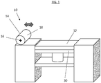
- the machine includes a build plate 12 upon which a workpiece (not shown) is formed by a laser powder bed fusion process.
- the machine 10 further includes a recoater 14.
- the recoater 14 in some embodiments, is a cylinder of, for example, tungsten carbide, that periodically advances across the build plate 12 to compress the powder material to improve formation of the workpiece.
- the recoater 14 may, for example, be formed entirely from tungsten carbide, or alternatively may have a recoater outer surface 18 formed from, for example, tungsten carbide, while an interior portion of the recoater 14 is formed from a different material.
- the recoater 14 may be rotated about a recoater axis 16. While in the embodiment of FIG. 1 the recoater 14 is configured to rotate about the recoater axis 16, it is to be appreciated that in other embodiments that the recoater 14 may be fixed at the recoater axis 16.
- Use of a recoater 14 with a debris buildup may lead to uneven application of pressure to the workpiece by the recoater 14, and thus uneven compression of the material powder by the recoater 14. Uneven compression may result in failure of the build of the workpiece.
- a cleaning fixture 20 is utilized to clean the recoater 14 as needed.
- the cleaning fixture 20 is secured to the build plate 12 by, for example, a snap fit. It is to be appreciated that in other embodiments other means may be utilized to secure the cleaning fixture 20 to the build plate 12, such as bolts, clamps, or the like.
- the cleaning fixture 20 includes a cleaning element 22, for example, a diamond sponge, that is configured to dislodge debris or other unwanted material from the recoater outer surface 18 when the recoater 14 is in contact with the cleaning element 22 and rotated about the recoater axis 16.
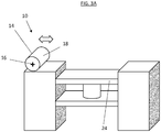
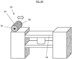
- FIGs. 3A - 3H a method of cleaning the recoater 14 utilizing the cleaning fixture 20 will now be described.
- the recoater 14 and a sinter piston 24 are positioned in their respective home positions.
- the cleaning fixture 20 including the cleaning element 22 is secured to the build plate 12 via, for example, a snap connection.
- the build plate 12 and the cleaning fixture 20 are loaded into the machine 10 and placed atop the sinter piston 24.
- the build plate 12 and the cleaning fixture 20 may be loaded into the machine 10 via either standard machine 10 loading procedures, or alternatively through manual methods. The loading does not require override of machine 10 safety interlocks, nor require an operator to put their hands in a live machine.
- FIG. 3D once the cleaning fixture 20 is loaded onto the sinter piston 24, the sinter piston 24 position is lowered until a sponge height of the cleaning element 22 is below the recoater outer surface 18.
- the recoater 14 is advanced from its home position 26 to a cleaning position 28 over the cleaning element 22.
- the recoater14 is rotated about the recoater axis 16 at the cleaning element 22 such that frictional contact between the cleaning element 22 and the recoater outer surface 18 dislodges the debris, smooths out scratches or other damage in the recoater outer surface 18, and the like.
- the rotation of the recoater 14 may be repeated as necessary or desired, until a desired condition of the recoater outer surface 18 is achieved.
- the recoater is returned to the home position 26 as illustrated in FIG. 3G .
- the cleaning fixture 20 and the build plate 12 are removed, and the machine may be returned to normal operation.
- the cleaning fixture 20 and cleaning method described herein allow for repeatable, controlled cleaning of the recoater 14, thereby improving operation of the machine 10. Utilizing the cleaning fixture 20 automates the cleaning process, such that a machine operator need not defeat machine safety features and place hands in the machine 10 to achieve cleaning of the recoater 14. Further, the cleaning fixture 20 may be equipped with multiple cleaning elements 22 to reduce cleaning time of the recoater 14.
Landscapes
- Chemical & Material Sciences (AREA)
- Engineering & Computer Science (AREA)
- Materials Engineering (AREA)
- Manufacturing & Machinery (AREA)
- Physics & Mathematics (AREA)
- Optics & Photonics (AREA)
- Mechanical Engineering (AREA)
- Powder Metallurgy (AREA)
Abstract
Description
- Exemplary embodiments pertain to the art of additive manufacturing. In particular, the present disclosure relates to cleaning of a recoater apparatus of an additive manufacturing machine.
- Additive manufacturing methods and apparatuses are utilized to manufacture components of selected shapes or sizes, most often by deposition of a powder material. In one such method, referred to as laser powder bed fusion (LPBF), a recoater is utilized to compact the deposited material powder, enabling better heat transfer in the deposited powder, and allowing for steeper unsupported angles in the component and improved uniformity in deposited layers of material powder.
- In other apparatuses, the recoater is a cylindrical element, more specifically described as a rolling style hard recoater that is advanced over the deposited material to compact the material as it rolls. The recoater becomes dirty and/or damaged with use, deterring its usefulness or even making the use of the recoater a liability. Debris on the recoater can cause uneven powder spreading, scratching of build plates and the potential for debris to impact the building components. These issues may be avoided by periodically cleaning the recoater, and the art would readily appreciate advances in tools in methods for cleaning the recoater.
- In one embodiment, a method of cleaning a recoater of an additive manufacturing machine includes installing a cleaning fixture into the additive manufacturing machine, the cleaning fixture including one or more cleaning elements, advancing the recoater into contact with the one or more cleaning elements, and rotating the recoater about a recoater axis thus dislodging material from a recoater outer surface due to frictional contact with the one or more cleaning elements.
- Additionally or alternatively, in this or other embodiments the cleaning fixture is installed into the additive manufacturing machine while the recoater is positioned in a home position.
- Additionally or alternatively, in this or other embodiments the recoater is advanced from the home position to a cleaning position over the one or more cleaning elements prior to advancing the recoater into contact with the one or more cleaning elements.
- Additionally or alternatively, in this or other embodiments the cleaning fixture is installed via a build plate of the additive manufacturing machine.
- Additionally or alternatively, in this or other embodiments the cleaning fixture is secured to the build plate via one of a snap connection, one or more clamps or one or more bolts.
- Additionally or alternatively, in this or other embodiments the build plate and the cleaning fixture are installed to a sintering piston of the additive manufacturing machine.
- Additionally or alternatively, in this or other embodiments the one or more cleaning elements is one or more diamond sponges.
- Additionally or alternatively, in this or other embodiments the cleaning fixture is installed into the additive manufacturing machine without defeating machine safety features.
- In another embodiment, an additive manufacturing machine includes a build plate, a powder source configured to selectably distribute a powdered material at the build plate for manufacturing, and a recoater configured to advance over the item being manufactured and compress the distributed powder material. The recoater is configured to advance from a home position to contact with the item being manufactured and return to the home position, the recoater further configured to rotate about a recoater axis. A cleaning fixture for the recoater is installable to the build plate. The build plate includes one or more cleaning elements configured to remove material from an outer surface of the recoater as the recoater rotates about the recoater axis via frictional contact between the recoater and the one or more cleaning elements.
- Additionally or alternatively, in this or other embodiments the cleaning fixture is secured to the build plate via one of a snap connection, one or more clamps or one or more bolts.
- Additionally or alternatively, in this or other embodiments the one or more cleaning elements is one or more diamond sponges.
- Additionally or alternatively, in this or other embodiments the cleaning fixture and the build plate are installable to a sintering piston of the additive manufacturing machine.
- Additionally or alternatively, in this or other embodiments the cleaning fixture is installed into the additive manufacturing machine while the recoater is positioned in the home position.
- Additionally or alternatively, in this or other embodiments the recoater is advanced from the home position to a cleaning position over the one or more cleaning elements prior to advancing the recoater into contact with the one or more cleaning elements.
- Additionally or alternatively, in this or other embodiments the recoater is a cylindrical element.
- The following descriptions should not be considered limiting in any way. With reference to the accompanying drawings, like elements are numbered alike:
-
FIG. 1 is a schematic illustration of an embodiment of an additive manufacturing machine; -
FIG. 2 is a schematic illustration of an embodiment of a cleaning fixture configured to clean a recoater of an additive manufacturing machine; and -
FIGs. 3A-3H illustrate steps in a method of cleaning a recoater of an additive manufacturing machine. - A detailed description of one or more embodiments of the disclosed apparatus and method are presented herein by way of exemplification and not limitation with reference to the Figures.
- Referring to
FIG. 1 , shown is a schematic illustration of anadditive manufacturing machine 10.. The machine includes abuild plate 12 upon which a workpiece (not shown) is formed by a laser powder bed fusion process. Themachine 10 further includes arecoater 14. Therecoater 14, in some embodiments, is a cylinder of, for example, tungsten carbide, that periodically advances across thebuild plate 12 to compress the powder material to improve formation of the workpiece. Therecoater 14 may, for example, be formed entirely from tungsten carbide, or alternatively may have a recoaterouter surface 18 formed from, for example, tungsten carbide, while an interior portion of therecoater 14 is formed from a different material. In advancing across thebuild plate 12, therecoater 14 may be rotated about arecoater axis 16. While in the embodiment ofFIG. 1 therecoater 14 is configured to rotate about therecoater axis 16, it is to be appreciated that in other embodiments that therecoater 14 may be fixed at therecoater axis 16. Use of therecoater 14, however, leads to buildup of material powder and other debris on the recoaterouter surface 18. Use of arecoater 14 with a debris buildup may lead to uneven application of pressure to the workpiece by therecoater 14, and thus uneven compression of the material powder by therecoater 14. Uneven compression may result in failure of the build of the workpiece. - Referring now to
FIG. 2 , acleaning fixture 20 is utilized to clean therecoater 14 as needed. Thecleaning fixture 20 is secured to thebuild plate 12 by, for example, a snap fit. It is to be appreciated that in other embodiments other means may be utilized to secure thecleaning fixture 20 to thebuild plate 12, such as bolts, clamps, or the like. Thecleaning fixture 20 includes acleaning element 22, for example, a diamond sponge, that is configured to dislodge debris or other unwanted material from the recoaterouter surface 18 when therecoater 14 is in contact with thecleaning element 22 and rotated about therecoater axis 16. - Referring now to
FIGs. 3A - 3H , a method of cleaning therecoater 14 utilizing thecleaning fixture 20 will now be described. InFIG. 3A , at the beginning of the method, therecoater 14 and asinter piston 24 are positioned in their respective home positions. InFIG. 3B , thecleaning fixture 20 including thecleaning element 22 is secured to thebuild plate 12 via, for example, a snap connection. - Referring now to
FIG. 3C , thebuild plate 12 and thecleaning fixture 20 are loaded into themachine 10 and placed atop thesinter piston 24. Thebuild plate 12 and thecleaning fixture 20 may be loaded into themachine 10 via eitherstandard machine 10 loading procedures, or alternatively through manual methods. The loading does not require override ofmachine 10 safety interlocks, nor require an operator to put their hands in a live machine. InFIG. 3D , once thecleaning fixture 20 is loaded onto thesinter piston 24, thesinter piston 24 position is lowered until a sponge height of thecleaning element 22 is below the recoaterouter surface 18. - Next, as shown in
FIG. 3E , therecoater 14 is advanced from itshome position 26 to acleaning position 28 over thecleaning element 22. Referring toFIG. 3F , to remove debris and other material from the recoaterouter surface 18, the recoater14 is rotated about therecoater axis 16 at thecleaning element 22 such that frictional contact between the cleaningelement 22 and the recoaterouter surface 18 dislodges the debris, smooths out scratches or other damage in the recoaterouter surface 18, and the like. The rotation of therecoater 14 may be repeated as necessary or desired, until a desired condition of the recoaterouter surface 18 is achieved. - Once the selected recoater
outer surface 18 condition is achieved, the recoater is returned to thehome position 26 as illustrated inFIG. 3G . Finally, as shown inFIG. 3H , thecleaning fixture 20 and thebuild plate 12 are removed, and the machine may be returned to normal operation. - The
cleaning fixture 20 and cleaning method described herein allow for repeatable, controlled cleaning of therecoater 14, thereby improving operation of themachine 10. Utilizing thecleaning fixture 20 automates the cleaning process, such that a machine operator need not defeat machine safety features and place hands in themachine 10 to achieve cleaning of therecoater 14. Further, thecleaning fixture 20 may be equipped withmultiple cleaning elements 22 to reduce cleaning time of therecoater 14. - The term "about" is intended to include the degree of error associated with measurement of the particular quantity based upon the equipment available at the time of filing the application.
- The terminology used herein is for the purpose of describing particular embodiments only and is not intended to be limiting of the present disclosure. As used herein, the singular forms "a", "an" and "the" are intended to include the plural forms as well, unless the context clearly indicates otherwise. It will be further understood that the terms "comprises" and/or "comprising," when used in this specification, specify the presence of stated features, integers, steps, operations, elements, and/or components, but do not preclude the presence or addition of one or more other features, integers, steps, operations, element components, and/or groups thereof.
- While the present disclosure has been described with reference to an exemplary embodiment or embodiments, it will be understood by those skilled in the art that various changes may be made and equivalents may be substituted for elements thereof without departing from the scope of the present disclosure. In addition, many modifications may be made to adapt a particular situation or material to the teachings of the present disclosure without departing from the essential scope thereof. Therefore, it is intended that the present disclosure not be limited to the particular embodiment disclosed as the best mode contemplated for carrying out this present disclosure, but that the present disclosure will include all embodiments falling within the scope of the claims.
Claims (15)
- A method of cleaning a recoater (14) of an additive manufacturing machine (10), comprising:installing a cleaning fixture (20) into the additive manufacturing machine (10), the cleaning fixture (20) including one or more cleaning elements (22);advancing the recoater (14) into contact with the one or more cleaning elements (22); androtating the recoater (14) about a recoater axis (16) thus dislodging material from a recoater outer surface due to frictional contact with the one or more cleaning elements (22).
- The method of claim 1, further comprising installing the cleaning fixture (20) into the additive manufacturing machine (10) while the recoater (14) is positioned in a home position.
- The method of claim 2, further comprising advancing the recoater (14) from the home position to a cleaning position over the one or more cleaning elements (22) prior to advancing the recoater (14) into contact with the one or more cleaning elements (22).
- The method of any preceding claim, further comprising installing the cleaning fixture (20) via a build plate (12) of the additive manufacturing machine.
- The method of claim 4, wherein the cleaning fixture (120) is secured to the build plate (12) via one of a snap connection, one or more clamps or one or more bolts.
- The method of claim 4, wherein the build plate (12) and the cleaning fixture (20) are installed to a sintering piston of the additive manufacturing machine.
- The method of any preceding claim, wherein the one or more cleaning elements (22) is one or more diamond sponges.
- The method of any preceding claim, wherein the cleaning fixture (20) is installed into the additive manufacturing machine (10) without defeating machine safety features.
- An additive manufacturing machine (10) comprising:a build plate (12);a powder source configured to selectably distribute a powdered material at the build plate (12) for manufacturing;a recoater (14) configured to advance over the item being manufactured and compress the distributed powder material, wherein the recoater (14) is configured to advance from a home position to contact with the item being manufactured and return to the home position, the recoater (14) further configured to rotate about a recoater axis (16); anda cleaning fixture (20) for the recoater installable to the build plate (12), the build plate (12) including one or more cleaning elements (22) configured to remove material from an outer surface of the recoater (14) as the recoater (14) rotates about the recoater axis (16) via frictional contact between the recoater and the one or more cleaning elements (22).
- The additive manufacturing machine of claim 9, wherein the cleaning fixture (20) is secured to the build plate (12) via one of a snap connection, one or more clamps or one or more bolts.
- The additive manufacturing machine of claims 9 or 10, wherein the one or more cleaning elements (22) is one or more diamond sponges.
- The additive manufacturing machine of any of claims 9 to 11, wherein the cleaning fixture (20) and the build plate (12) are installable to a sintering piston of the additive manufacturing machine (10).
- The additive manufacturing machine of any of claims 9 to 12, further comprising installing the cleaning fixture (20) into the additive manufacturing machine (10) while the recoater (14) is positioned in the home position.
- The additive manufacturing machine of claim 13, further comprising advancing the recoater (14) from the home position to a cleaning position over the one or more cleaning elements (22) prior to advancing the recoater (14) into contact with the one or more cleaning elements.
- The additive manufacturing machine of any of claims 9 to 14, wherein the recoater (14) is a cylindrical element.
Applications Claiming Priority (1)
| Application Number | Priority Date | Filing Date | Title |
|---|---|---|---|
| US2018969440 | 2018-05-02 |
Publications (2)
| Publication Number | Publication Date |
|---|---|
| EP3564035A1 true EP3564035A1 (en) | 2019-11-06 |
| EP3564035B1 EP3564035B1 (en) | 2021-06-30 |
Family
ID=66379829
Family Applications (1)
| Application Number | Title | Priority Date | Filing Date |
|---|---|---|---|
| EP19172356.8A Active EP3564035B1 (en) | 2018-05-02 | 2019-05-02 | Fixture and method of cleaning additive manufacturing machine components |
Country Status (1)
| Country | Link |
|---|---|
| EP (1) | EP3564035B1 (en) |
Citations (4)
| Publication number | Priority date | Publication date | Assignee | Title |
|---|---|---|---|---|
| EP1552905A2 (en) * | 2001-05-02 | 2005-07-13 | Nihon Micro Coating Co., Ltd. | Contactor cleaning sheet, contactor cleaning sheet manufacturing method, and contactor cleaning method |
| US20160067929A1 (en) * | 2014-09-09 | 2016-03-10 | Ricoh Company, Ltd. | Apparatus for fabricating three-dimensional object |
| CN105562689A (en) * | 2015-11-26 | 2016-05-11 | 阳江市五金刀剪产业技术研究院 | Bothway powder paving powder based additive material manufacturing device and powder paving method thereof |
| GB2550341A (en) * | 2016-05-12 | 2017-11-22 | Hewlett Packard Development Co Lp | Build Material Distributor Cleaning Element |
-
2019
- 2019-05-02 EP EP19172356.8A patent/EP3564035B1/en active Active
Patent Citations (4)
| Publication number | Priority date | Publication date | Assignee | Title |
|---|---|---|---|---|
| EP1552905A2 (en) * | 2001-05-02 | 2005-07-13 | Nihon Micro Coating Co., Ltd. | Contactor cleaning sheet, contactor cleaning sheet manufacturing method, and contactor cleaning method |
| US20160067929A1 (en) * | 2014-09-09 | 2016-03-10 | Ricoh Company, Ltd. | Apparatus for fabricating three-dimensional object |
| CN105562689A (en) * | 2015-11-26 | 2016-05-11 | 阳江市五金刀剪产业技术研究院 | Bothway powder paving powder based additive material manufacturing device and powder paving method thereof |
| GB2550341A (en) * | 2016-05-12 | 2017-11-22 | Hewlett Packard Development Co Lp | Build Material Distributor Cleaning Element |
Also Published As
| Publication number | Publication date |
|---|---|
| EP3564035B1 (en) | 2021-06-30 |
Similar Documents
| Publication | Publication Date | Title |
|---|---|---|
| US11433615B2 (en) | Fixture and method of cleaning additive manufacturing machine components | |
| EP2830828B1 (en) | Method for the multi-stage grinding of workpieces | |
| EP3351345B1 (en) | Grinding device for grinding flat grinding material | |
| WO2010008824A2 (en) | Closed-loop control for effective pad conditioning | |
| TW201446421A (en) | Polishing pad cleaning with vacuum apparatus | |
| DE102014004633A1 (en) | Device for producing three-dimensional objects by successively solidifying layers | |
| EP3564035B1 (en) | Fixture and method of cleaning additive manufacturing machine components | |
| DE10345381B4 (en) | A method and system for controlling chemical mechanical polishing using a sensor signal from a pad conditioner | |
| CN107206566A (en) | Surface grinder | |
| DE202017100307U1 (en) | Grinding device for grinding flat abrasive material | |
| CN109395953A (en) | A kind of metal, plastics, timber automation paint equipment | |
| WO2017067884A1 (en) | An apparatus for dressing a grinding wheel | |
| CN105081547A (en) | Welding Controller and Method for Controlling a Welding Operation | |
| EP2514541A2 (en) | Device and method for producing a green compact from a powder or granular material | |
| US2120455A (en) | Rotary filter | |
| EP2301714B1 (en) | Surface grinding machine and method for operating and/or maintaining a surface grinding machine | |
| EP3482114B1 (en) | Powder rotary feedthrough having a purge chamber | |
| EP3370916A1 (en) | Method and device for producing a homogeneous, ground surface of a metal strip | |
| WO2013136350A1 (en) | Machine and method for restoring the functionality of abrasive disks | |
| JP2018076233A (en) | Filling equipment | |
| EP3224508B1 (en) | Sliding ring or counter ring for a sliding ring seal | |
| EP4549116A1 (en) | Powder spreader and method of spreading powder in an interior of a die | |
| EP4724243A1 (en) | Powder spreader and method of spreading powder in an interior of a cylindrical die | |
| JPH0724715A (en) | Online end face brushing equipment for steel products | |
| DE3913613A1 (en) | Methods for regenerating a photoreceptor for electrophotography |
Legal Events
| Date | Code | Title | Description |
|---|---|---|---|
| PUAI | Public reference made under article 153(3) epc to a published international application that has entered the european phase |
Free format text: ORIGINAL CODE: 0009012 |
|
| STAA | Information on the status of an ep patent application or granted ep patent |
Free format text: STATUS: THE APPLICATION HAS BEEN PUBLISHED |
|
| AK | Designated contracting states |
Kind code of ref document: A1 Designated state(s): AL AT BE BG CH CY CZ DE DK EE ES FI FR GB GR HR HU IE IS IT LI LT LU LV MC MK MT NL NO PL PT RO RS SE SI SK SM TR |
|
| AX | Request for extension of the european patent |
Extension state: BA ME |
|
| STAA | Information on the status of an ep patent application or granted ep patent |
Free format text: STATUS: REQUEST FOR EXAMINATION WAS MADE |
|
| 17P | Request for examination filed |
Effective date: 20191202 |
|
| RBV | Designated contracting states (corrected) |
Designated state(s): AL AT BE BG CH CY CZ DE DK EE ES FI FR GB GR HR HU IE IS IT LI LT LU LV MC MK MT NL NO PL PT RO RS SE SI SK SM TR |
|
| GRAP | Despatch of communication of intention to grant a patent |
Free format text: ORIGINAL CODE: EPIDOSNIGR1 |
|
| STAA | Information on the status of an ep patent application or granted ep patent |
Free format text: STATUS: GRANT OF PATENT IS INTENDED |
|
| INTG | Intention to grant announced |
Effective date: 20201203 |
|
| RIN1 | Information on inventor provided before grant (corrected) |
Inventor name: MADINGER, ALEXANDER Inventor name: GIULIETTI, DIANA |
|
| GRAS | Grant fee paid |
Free format text: ORIGINAL CODE: EPIDOSNIGR3 |
|
| GRAA | (expected) grant |
Free format text: ORIGINAL CODE: 0009210 |
|
| STAA | Information on the status of an ep patent application or granted ep patent |
Free format text: STATUS: THE PATENT HAS BEEN GRANTED |
|
| AK | Designated contracting states |
Kind code of ref document: B1 Designated state(s): AL AT BE BG CH CY CZ DE DK EE ES FI FR GB GR HR HU IE IS IT LI LT LU LV MC MK MT NL NO PL PT RO RS SE SI SK SM TR |
|
| REG | Reference to a national code |
Ref country code: CH Ref legal event code: EP |
|
| REG | Reference to a national code |
Ref country code: DE Ref legal event code: R096 Ref document number: 602019005661 Country of ref document: DE Ref country code: AT Ref legal event code: REF Ref document number: 1405992 Country of ref document: AT Kind code of ref document: T Effective date: 20210715 |
|
| REG | Reference to a national code |
Ref country code: IE Ref legal event code: FG4D |
|
| REG | Reference to a national code |
Ref country code: LT Ref legal event code: MG9D |
|
| PG25 | Lapsed in a contracting state [announced via postgrant information from national office to epo] |
Ref country code: FI Free format text: LAPSE BECAUSE OF FAILURE TO SUBMIT A TRANSLATION OF THE DESCRIPTION OR TO PAY THE FEE WITHIN THE PRESCRIBED TIME-LIMIT Effective date: 20210630 Ref country code: HR Free format text: LAPSE BECAUSE OF FAILURE TO SUBMIT A TRANSLATION OF THE DESCRIPTION OR TO PAY THE FEE WITHIN THE PRESCRIBED TIME-LIMIT Effective date: 20210630 Ref country code: BG Free format text: LAPSE BECAUSE OF FAILURE TO SUBMIT A TRANSLATION OF THE DESCRIPTION OR TO PAY THE FEE WITHIN THE PRESCRIBED TIME-LIMIT Effective date: 20210930 |
|
| REG | Reference to a national code |
Ref country code: NL Ref legal event code: MP Effective date: 20210630 |
|
| REG | Reference to a national code |
Ref country code: AT Ref legal event code: MK05 Ref document number: 1405992 Country of ref document: AT Kind code of ref document: T Effective date: 20210630 |
|
| PG25 | Lapsed in a contracting state [announced via postgrant information from national office to epo] |
Ref country code: SE Free format text: LAPSE BECAUSE OF FAILURE TO SUBMIT A TRANSLATION OF THE DESCRIPTION OR TO PAY THE FEE WITHIN THE PRESCRIBED TIME-LIMIT Effective date: 20210630 Ref country code: RS Free format text: LAPSE BECAUSE OF FAILURE TO SUBMIT A TRANSLATION OF THE DESCRIPTION OR TO PAY THE FEE WITHIN THE PRESCRIBED TIME-LIMIT Effective date: 20210630 Ref country code: NO Free format text: LAPSE BECAUSE OF FAILURE TO SUBMIT A TRANSLATION OF THE DESCRIPTION OR TO PAY THE FEE WITHIN THE PRESCRIBED TIME-LIMIT Effective date: 20210930 Ref country code: LV Free format text: LAPSE BECAUSE OF FAILURE TO SUBMIT A TRANSLATION OF THE DESCRIPTION OR TO PAY THE FEE WITHIN THE PRESCRIBED TIME-LIMIT Effective date: 20210630 Ref country code: GR Free format text: LAPSE BECAUSE OF FAILURE TO SUBMIT A TRANSLATION OF THE DESCRIPTION OR TO PAY THE FEE WITHIN THE PRESCRIBED TIME-LIMIT Effective date: 20211001 |
|
| PG25 | Lapsed in a contracting state [announced via postgrant information from national office to epo] |
Ref country code: EE Free format text: LAPSE BECAUSE OF FAILURE TO SUBMIT A TRANSLATION OF THE DESCRIPTION OR TO PAY THE FEE WITHIN THE PRESCRIBED TIME-LIMIT Effective date: 20210630 Ref country code: ES Free format text: LAPSE BECAUSE OF FAILURE TO SUBMIT A TRANSLATION OF THE DESCRIPTION OR TO PAY THE FEE WITHIN THE PRESCRIBED TIME-LIMIT Effective date: 20210630 Ref country code: SK Free format text: LAPSE BECAUSE OF FAILURE TO SUBMIT A TRANSLATION OF THE DESCRIPTION OR TO PAY THE FEE WITHIN THE PRESCRIBED TIME-LIMIT Effective date: 20210630 Ref country code: SM Free format text: LAPSE BECAUSE OF FAILURE TO SUBMIT A TRANSLATION OF THE DESCRIPTION OR TO PAY THE FEE WITHIN THE PRESCRIBED TIME-LIMIT Effective date: 20210630 Ref country code: RO Free format text: LAPSE BECAUSE OF FAILURE TO SUBMIT A TRANSLATION OF THE DESCRIPTION OR TO PAY THE FEE WITHIN THE PRESCRIBED TIME-LIMIT Effective date: 20210630 Ref country code: PT Free format text: LAPSE BECAUSE OF FAILURE TO SUBMIT A TRANSLATION OF THE DESCRIPTION OR TO PAY THE FEE WITHIN THE PRESCRIBED TIME-LIMIT Effective date: 20211102 Ref country code: NL Free format text: LAPSE BECAUSE OF FAILURE TO SUBMIT A TRANSLATION OF THE DESCRIPTION OR TO PAY THE FEE WITHIN THE PRESCRIBED TIME-LIMIT Effective date: 20210630 Ref country code: CZ Free format text: LAPSE BECAUSE OF FAILURE TO SUBMIT A TRANSLATION OF THE DESCRIPTION OR TO PAY THE FEE WITHIN THE PRESCRIBED TIME-LIMIT Effective date: 20210630 Ref country code: AT Free format text: LAPSE BECAUSE OF FAILURE TO SUBMIT A TRANSLATION OF THE DESCRIPTION OR TO PAY THE FEE WITHIN THE PRESCRIBED TIME-LIMIT Effective date: 20210630 |
|
| PG25 | Lapsed in a contracting state [announced via postgrant information from national office to epo] |
Ref country code: PL Free format text: LAPSE BECAUSE OF FAILURE TO SUBMIT A TRANSLATION OF THE DESCRIPTION OR TO PAY THE FEE WITHIN THE PRESCRIBED TIME-LIMIT Effective date: 20210630 |
|
| REG | Reference to a national code |
Ref country code: DE Ref legal event code: R097 Ref document number: 602019005661 Country of ref document: DE |
|
| PG25 | Lapsed in a contracting state [announced via postgrant information from national office to epo] |
Ref country code: DK Free format text: LAPSE BECAUSE OF FAILURE TO SUBMIT A TRANSLATION OF THE DESCRIPTION OR TO PAY THE FEE WITHIN THE PRESCRIBED TIME-LIMIT Effective date: 20210630 |
|
| PLBE | No opposition filed within time limit |
Free format text: ORIGINAL CODE: 0009261 |
|
| STAA | Information on the status of an ep patent application or granted ep patent |
Free format text: STATUS: NO OPPOSITION FILED WITHIN TIME LIMIT |
|
| PG25 | Lapsed in a contracting state [announced via postgrant information from national office to epo] |
Ref country code: AL Free format text: LAPSE BECAUSE OF FAILURE TO SUBMIT A TRANSLATION OF THE DESCRIPTION OR TO PAY THE FEE WITHIN THE PRESCRIBED TIME-LIMIT Effective date: 20210630 |
|
| 26N | No opposition filed |
Effective date: 20220331 |
|
| PG25 | Lapsed in a contracting state [announced via postgrant information from national office to epo] |
Ref country code: IT Free format text: LAPSE BECAUSE OF FAILURE TO SUBMIT A TRANSLATION OF THE DESCRIPTION OR TO PAY THE FEE WITHIN THE PRESCRIBED TIME-LIMIT Effective date: 20210630 |
|
| REG | Reference to a national code |
Ref country code: CH Ref legal event code: PL |
|
| REG | Reference to a national code |
Ref country code: BE Ref legal event code: MM Effective date: 20220531 |
|
| PG25 | Lapsed in a contracting state [announced via postgrant information from national office to epo] |
Ref country code: MC Free format text: LAPSE BECAUSE OF FAILURE TO SUBMIT A TRANSLATION OF THE DESCRIPTION OR TO PAY THE FEE WITHIN THE PRESCRIBED TIME-LIMIT Effective date: 20210630 Ref country code: LU Free format text: LAPSE BECAUSE OF NON-PAYMENT OF DUE FEES Effective date: 20220502 Ref country code: LI Free format text: LAPSE BECAUSE OF NON-PAYMENT OF DUE FEES Effective date: 20220531 Ref country code: CH Free format text: LAPSE BECAUSE OF NON-PAYMENT OF DUE FEES Effective date: 20220531 |
|
| PG25 | Lapsed in a contracting state [announced via postgrant information from national office to epo] |
Ref country code: LT Free format text: LAPSE BECAUSE OF FAILURE TO SUBMIT A TRANSLATION OF THE DESCRIPTION OR TO PAY THE FEE WITHIN THE PRESCRIBED TIME-LIMIT Effective date: 20210630 Ref country code: IE Free format text: LAPSE BECAUSE OF NON-PAYMENT OF DUE FEES Effective date: 20220502 |
|
| PG25 | Lapsed in a contracting state [announced via postgrant information from national office to epo] |
Ref country code: BE Free format text: LAPSE BECAUSE OF NON-PAYMENT OF DUE FEES Effective date: 20220531 |
|
| P01 | Opt-out of the competence of the unified patent court (upc) registered |
Effective date: 20230522 |
|
| PG25 | Lapsed in a contracting state [announced via postgrant information from national office to epo] |
Ref country code: HU Free format text: LAPSE BECAUSE OF FAILURE TO SUBMIT A TRANSLATION OF THE DESCRIPTION OR TO PAY THE FEE WITHIN THE PRESCRIBED TIME-LIMIT; INVALID AB INITIO Effective date: 20190502 |
|
| PG25 | Lapsed in a contracting state [announced via postgrant information from national office to epo] |
Ref country code: MK Free format text: LAPSE BECAUSE OF FAILURE TO SUBMIT A TRANSLATION OF THE DESCRIPTION OR TO PAY THE FEE WITHIN THE PRESCRIBED TIME-LIMIT Effective date: 20210630 Ref country code: CY Free format text: LAPSE BECAUSE OF FAILURE TO SUBMIT A TRANSLATION OF THE DESCRIPTION OR TO PAY THE FEE WITHIN THE PRESCRIBED TIME-LIMIT Effective date: 20210630 |
|
| PG25 | Lapsed in a contracting state [announced via postgrant information from national office to epo] |
Ref country code: TR Free format text: LAPSE BECAUSE OF FAILURE TO SUBMIT A TRANSLATION OF THE DESCRIPTION OR TO PAY THE FEE WITHIN THE PRESCRIBED TIME-LIMIT Effective date: 20210630 |
|
| PG25 | Lapsed in a contracting state [announced via postgrant information from national office to epo] |
Ref country code: MT Free format text: LAPSE BECAUSE OF FAILURE TO SUBMIT A TRANSLATION OF THE DESCRIPTION OR TO PAY THE FEE WITHIN THE PRESCRIBED TIME-LIMIT Effective date: 20210630 |
|
| PGFP | Annual fee paid to national office [announced via postgrant information from national office to epo] |
Ref country code: DE Payment date: 20250423 Year of fee payment: 7 |
|
| PGFP | Annual fee paid to national office [announced via postgrant information from national office to epo] |
Ref country code: GB Payment date: 20250423 Year of fee payment: 7 |
|
| PGFP | Annual fee paid to national office [announced via postgrant information from national office to epo] |
Ref country code: FR Payment date: 20250423 Year of fee payment: 7 |