EP3564007B1 - Verfahren zum bilden eines gespannten längsträgers für ein fahrzeug - Google Patents
Verfahren zum bilden eines gespannten längsträgers für ein fahrzeug Download PDFInfo
- Publication number
- EP3564007B1 EP3564007B1 EP19157346.8A EP19157346A EP3564007B1 EP 3564007 B1 EP3564007 B1 EP 3564007B1 EP 19157346 A EP19157346 A EP 19157346A EP 3564007 B1 EP3564007 B1 EP 3564007B1
- Authority
- EP
- European Patent Office
- Prior art keywords
- charges
- die cavity
- die
- vehicle
- section
- Prior art date
- Legal status (The legal status is an assumption and is not a legal conclusion. Google has not performed a legal analysis and makes no representation as to the accuracy of the status listed.)
- Active
Links
Images


Classifications
-
- B—PERFORMING OPERATIONS; TRANSPORTING
- B29—WORKING OF PLASTICS; WORKING OF SUBSTANCES IN A PLASTIC STATE IN GENERAL
- B29C—SHAPING OR JOINING OF PLASTICS; SHAPING OF MATERIAL IN A PLASTIC STATE, NOT OTHERWISE PROVIDED FOR; AFTER-TREATMENT OF THE SHAPED PRODUCTS, e.g. REPAIRING
- B29C53/00—Shaping by bending, folding, twisting, straightening or flattening; Apparatus therefor
- B29C53/02—Bending or folding
- B29C53/04—Bending or folding of plates or sheets
- B29C53/06—Forming folding lines by pressing or scoring
-
- B—PERFORMING OPERATIONS; TRANSPORTING
- B29—WORKING OF PLASTICS; WORKING OF SUBSTANCES IN A PLASTIC STATE IN GENERAL
- B29C—SHAPING OR JOINING OF PLASTICS; SHAPING OF MATERIAL IN A PLASTIC STATE, NOT OTHERWISE PROVIDED FOR; AFTER-TREATMENT OF THE SHAPED PRODUCTS, e.g. REPAIRING
- B29C53/00—Shaping by bending, folding, twisting, straightening or flattening; Apparatus therefor
- B29C53/80—Component parts, details or accessories; Auxiliary operations
- B29C53/82—Cores or mandrels
-
- B—PERFORMING OPERATIONS; TRANSPORTING
- B29—WORKING OF PLASTICS; WORKING OF SUBSTANCES IN A PLASTIC STATE IN GENERAL
- B29C—SHAPING OR JOINING OF PLASTICS; SHAPING OF MATERIAL IN A PLASTIC STATE, NOT OTHERWISE PROVIDED FOR; AFTER-TREATMENT OF THE SHAPED PRODUCTS, e.g. REPAIRING
- B29C53/00—Shaping by bending, folding, twisting, straightening or flattening; Apparatus therefor
- B29C53/80—Component parts, details or accessories; Auxiliary operations
- B29C53/84—Heating or cooling
-
- B—PERFORMING OPERATIONS; TRANSPORTING
- B29—WORKING OF PLASTICS; WORKING OF SUBSTANCES IN A PLASTIC STATE IN GENERAL
- B29C—SHAPING OR JOINING OF PLASTICS; SHAPING OF MATERIAL IN A PLASTIC STATE, NOT OTHERWISE PROVIDED FOR; AFTER-TREATMENT OF THE SHAPED PRODUCTS, e.g. REPAIRING
- B29C70/00—Shaping composites, i.e. plastics material comprising reinforcements, fillers or preformed parts, e.g. inserts
- B29C70/04—Shaping composites, i.e. plastics material comprising reinforcements, fillers or preformed parts, e.g. inserts comprising reinforcements only, e.g. self-reinforcing plastics
- B29C70/28—Shaping operations therefor
- B29C70/30—Shaping by lay-up, i.e. applying fibres, tape or broadsheet on a mould, former or core; Shaping by spray-up, i.e. spraying of fibres on a mould, former or core
- B29C70/304—In-plane lamination by juxtaposing or interleaving of plies, e.g. scarf joining
-
- B—PERFORMING OPERATIONS; TRANSPORTING
- B29—WORKING OF PLASTICS; WORKING OF SUBSTANCES IN A PLASTIC STATE IN GENERAL
- B29C—SHAPING OR JOINING OF PLASTICS; SHAPING OF MATERIAL IN A PLASTIC STATE, NOT OTHERWISE PROVIDED FOR; AFTER-TREATMENT OF THE SHAPED PRODUCTS, e.g. REPAIRING
- B29C70/00—Shaping composites, i.e. plastics material comprising reinforcements, fillers or preformed parts, e.g. inserts
- B29C70/04—Shaping composites, i.e. plastics material comprising reinforcements, fillers or preformed parts, e.g. inserts comprising reinforcements only, e.g. self-reinforcing plastics
- B29C70/28—Shaping operations therefor
- B29C70/40—Shaping or impregnating by compression not applied
- B29C70/42—Shaping or impregnating by compression not applied for producing articles of definite length, i.e. discrete articles
- B29C70/46—Shaping or impregnating by compression not applied for producing articles of definite length, i.e. discrete articles using matched moulds, e.g. for deforming sheet moulding compounds [SMC] or prepregs
- B29C70/461—Rigid movable compressing mould parts acting independently from opening or closing action of the main mould
-
- B—PERFORMING OPERATIONS; TRANSPORTING
- B29—WORKING OF PLASTICS; WORKING OF SUBSTANCES IN A PLASTIC STATE IN GENERAL
- B29C—SHAPING OR JOINING OF PLASTICS; SHAPING OF MATERIAL IN A PLASTIC STATE, NOT OTHERWISE PROVIDED FOR; AFTER-TREATMENT OF THE SHAPED PRODUCTS, e.g. REPAIRING
- B29C70/00—Shaping composites, i.e. plastics material comprising reinforcements, fillers or preformed parts, e.g. inserts
- B29C70/04—Shaping composites, i.e. plastics material comprising reinforcements, fillers or preformed parts, e.g. inserts comprising reinforcements only, e.g. self-reinforcing plastics
- B29C70/28—Shaping operations therefor
- B29C70/40—Shaping or impregnating by compression not applied
- B29C70/42—Shaping or impregnating by compression not applied for producing articles of definite length, i.e. discrete articles
- B29C70/46—Shaping or impregnating by compression not applied for producing articles of definite length, i.e. discrete articles using matched moulds, e.g. for deforming sheet moulding compounds [SMC] or prepregs
- B29C70/462—Moulding structures having an axis of symmetry or at least one channel, e.g. tubular structures, frames
-
- B—PERFORMING OPERATIONS; TRANSPORTING
- B29—WORKING OF PLASTICS; WORKING OF SUBSTANCES IN A PLASTIC STATE IN GENERAL
- B29C—SHAPING OR JOINING OF PLASTICS; SHAPING OF MATERIAL IN A PLASTIC STATE, NOT OTHERWISE PROVIDED FOR; AFTER-TREATMENT OF THE SHAPED PRODUCTS, e.g. REPAIRING
- B29C70/00—Shaping composites, i.e. plastics material comprising reinforcements, fillers or preformed parts, e.g. inserts
- B29C70/04—Shaping composites, i.e. plastics material comprising reinforcements, fillers or preformed parts, e.g. inserts comprising reinforcements only, e.g. self-reinforcing plastics
- B29C70/28—Shaping operations therefor
- B29C70/54—Component parts, details or accessories; Auxiliary operations, e.g. feeding or storage of prepregs or SMC after impregnation or during ageing
- B29C70/541—Positioning reinforcements in a mould, e.g. using clamping means for the reinforcement
-
- B—PERFORMING OPERATIONS; TRANSPORTING
- B29—WORKING OF PLASTICS; WORKING OF SUBSTANCES IN A PLASTIC STATE IN GENERAL
- B29C—SHAPING OR JOINING OF PLASTICS; SHAPING OF MATERIAL IN A PLASTIC STATE, NOT OTHERWISE PROVIDED FOR; AFTER-TREATMENT OF THE SHAPED PRODUCTS, e.g. REPAIRING
- B29C70/00—Shaping composites, i.e. plastics material comprising reinforcements, fillers or preformed parts, e.g. inserts
- B29C70/04—Shaping composites, i.e. plastics material comprising reinforcements, fillers or preformed parts, e.g. inserts comprising reinforcements only, e.g. self-reinforcing plastics
- B29C70/28—Shaping operations therefor
- B29C70/54—Component parts, details or accessories; Auxiliary operations, e.g. feeding or storage of prepregs or SMC after impregnation or during ageing
- B29C70/56—Tensioning reinforcements before or during shaping
-
- B—PERFORMING OPERATIONS; TRANSPORTING
- B29—WORKING OF PLASTICS; WORKING OF SUBSTANCES IN A PLASTIC STATE IN GENERAL
- B29D—PRODUCING PARTICULAR ARTICLES FROM PLASTICS OR FROM SUBSTANCES IN A PLASTIC STATE
- B29D99/00—Subject matter not provided for in other groups of this subclass
- B29D99/0003—Producing profiled members, e.g. beams
-
- B—PERFORMING OPERATIONS; TRANSPORTING
- B64—AIRCRAFT; AVIATION; COSMONAUTICS
- B64C—AEROPLANES; HELICOPTERS
- B64C1/00—Fuselages; Constructional features common to fuselages, wings, stabilising surfaces or the like
- B64C1/06—Frames; Stringers; Longerons ; Fuselage sections
- B64C1/064—Stringers; Longerons
-
- B—PERFORMING OPERATIONS; TRANSPORTING
- B64—AIRCRAFT; AVIATION; COSMONAUTICS
- B64C—AEROPLANES; HELICOPTERS
- B64C3/00—Wings
- B64C3/18—Spars; Ribs; Stringers
- B64C3/182—Stringers, longerons
-
- B—PERFORMING OPERATIONS; TRANSPORTING
- B64—AIRCRAFT; AVIATION; COSMONAUTICS
- B64F—GROUND OR AIRCRAFT-CARRIER-DECK INSTALLATIONS SPECIALLY ADAPTED FOR USE IN CONNECTION WITH AIRCRAFT; DESIGNING, MANUFACTURING, ASSEMBLING, CLEANING, MAINTAINING OR REPAIRING AIRCRAFT, NOT OTHERWISE PROVIDED FOR; HANDLING, TRANSPORTING, TESTING OR INSPECTING AIRCRAFT COMPONENTS, NOT OTHERWISE PROVIDED FOR
- B64F5/00—Designing, manufacturing, assembling, cleaning, maintaining or repairing aircraft, not otherwise provided for; Handling, transporting, testing or inspecting aircraft components, not otherwise provided for
- B64F5/10—Manufacturing or assembling aircraft, e.g. jigs therefor
-
- B—PERFORMING OPERATIONS; TRANSPORTING
- B29—WORKING OF PLASTICS; WORKING OF SUBSTANCES IN A PLASTIC STATE IN GENERAL
- B29C—SHAPING OR JOINING OF PLASTICS; SHAPING OF MATERIAL IN A PLASTIC STATE, NOT OTHERWISE PROVIDED FOR; AFTER-TREATMENT OF THE SHAPED PRODUCTS, e.g. REPAIRING
- B29C53/00—Shaping by bending, folding, twisting, straightening or flattening; Apparatus therefor
- B29C53/36—Bending and joining, e.g. for making hollow articles
-
- B—PERFORMING OPERATIONS; TRANSPORTING
- B29—WORKING OF PLASTICS; WORKING OF SUBSTANCES IN A PLASTIC STATE IN GENERAL
- B29K—INDEXING SCHEME ASSOCIATED WITH SUBCLASSES B29B, B29C OR B29D, RELATING TO MOULDING MATERIALS OR TO MATERIALS FOR MOULDS, REINFORCEMENTS, FILLERS OR PREFORMED PARTS, e.g. INSERTS
- B29K2105/00—Condition, form or state of moulded material or of the material to be shaped
- B29K2105/25—Solid
- B29K2105/253—Preform
- B29K2105/256—Sheets, plates, blanks or films
-
- B—PERFORMING OPERATIONS; TRANSPORTING
- B29—WORKING OF PLASTICS; WORKING OF SUBSTANCES IN A PLASTIC STATE IN GENERAL
- B29L—INDEXING SCHEME ASSOCIATED WITH SUBCLASS B29C, RELATING TO PARTICULAR ARTICLES
- B29L2031/00—Other particular articles
- B29L2031/30—Vehicles, e.g. ships or aircraft, or body parts thereof
- B29L2031/3076—Aircrafts
-
- Y—GENERAL TAGGING OF NEW TECHNOLOGICAL DEVELOPMENTS; GENERAL TAGGING OF CROSS-SECTIONAL TECHNOLOGIES SPANNING OVER SEVERAL SECTIONS OF THE IPC; TECHNICAL SUBJECTS COVERED BY FORMER USPC CROSS-REFERENCE ART COLLECTIONS [XRACs] AND DIGESTS
- Y02—TECHNOLOGIES OR APPLICATIONS FOR MITIGATION OR ADAPTATION AGAINST CLIMATE CHANGE
- Y02T—CLIMATE CHANGE MITIGATION TECHNOLOGIES RELATED TO TRANSPORTATION
- Y02T50/00—Aeronautics or air transport
- Y02T50/40—Weight reduction
Definitions
- the present disclosure generally relates to methods and devices for stringer fabrication. More particularly, the present disclosure relates to methods and devices for tensioning first and second charges during the formation of the stringer.
- Composite reinforcing substructures such as stringers, one example of which is referred to as blade stiffeners, are frequently used in various vehicles in the marine and aircraft industries.
- the stringers may be constructed from a single flat laminate.
- Existing forming methods for forming blade stringers from a single flat laminate include positioning the single flat laminate over a die cavity. A central section of the laminate extends over the die cavity with outer edges being positioned away from the die cavity. A punch die moves downward and forces the laminate into the die cavity. The section of the laminate that is moved into the die cavity forms a first section of the stringer. The sections at the ends of the laminate that remain out of the die cavity form a second section of the stringer.
- the single laminate design does not allow for the different, facing sides of the stringer to move independently during formation. This can result in anomalies to be created in the blade stiffener during certain punch forming configurations.
- Using a single laminate charge can also restrict the ability to create localized geometrical features on each of the different sides of the stringer within that one charge. Further, the first section of the laminate that is forced into the die cavity is in tension. However, the second sections of the laminate that remain out of the die cavity are not in tension.
- Document US 2009/0320995 A1 is relative to a device for the manufacture of three-dimensional beam type elements in composite material with reinforcing fibres preimpregnated with polymeric resins, starting with laminates layed and precut without polymerization, said device comprising a head that comprises in its turn a roller train, it being possible for said head to move longitudinally along a fixed bedplate, in such a way that, as said head moves, the roller train acts on the laminates without polymerization, compacting and forming them, thus forming laminates with their final geometry in one go, in such a way that said laminates are ready for their subsequent integration.
- Document US 2009/0320995 A1 also relates to a method of manufacture of three-dimensional beam type elements in composite material.
- Document WO 2015/011316 A1 relates to a mould for producing fibre stringers for aerospace structures, and to a method for producing fibre stringers with said mould, comprising a female tool and a male tool, by means of which a fibre laminate is formed, which is cut through the middle region in order to form two L-shaped profiles with which a T-shaped profile is formed, the female tool being formed by two facing side assemblies provided with inflatable membranes, while the male tool is formed by a central block and two side blocks, between which intermediate blocks are inserted, said intermediate blocks being, in turn, provided with inflatable membranes, in order to fold and join the two halves of the fibre laminate by means of a combined set of both tools and inflating the membranes.
- Document EP 2 868 465 A1 relates to a method of manufacturing T-shaped stringers made of composite material, comprising a second shaping step for shaping laminates into L-shaped preforms, which comprises providing a set of tools formed by a fixed tool comprising a lower portion and an upper portion, and a moveable tool comprising a lower element and an upper element. It also comprises the segment of the laminate intended for the foot of the preform being located between the lower portion and the upper portion of the fixed tool, and the segment of the laminate intended for the web of the preform being located between the lower element and the upper element of the moveable tool. It further comprises vertically moving the moveable tool to progressively bend the web of the preform supporting it on a vertical wall of the fixed tool. The end of its web adopts a rounded shape.
- Document US 2013/174396 A1 relates to an installation for manufacturing fiber stringers for aerospace structures formed by at least one swivel-mounted cylindrical carousel, peripherally incorporating a distribution of male configured tools and in relation to said carousel a bed capable of lateral movement, incorporating a distribution of female configured tools, a fiber strip applicator head for making fiber laminates on the male configured tools also being arranged in relation to the carousel, which allows making omega-shaped or T-shaped stringers by means of the interaction of each male configured tool of the carousel with a respective female configured tool of the bed.
- US 2013/174396 A1 discloses in particular a method comprising the following features: positioning first and second charges at a die cavity with first ends of each of the first and second charges extending over the die cavity; said first charge including a blade and a flange and said second charge including a blade and a flange; securing second ends of each of the first and second charges away from the die cavity; driving the first ends of each of the first and second charges into the die cavity while the second ends remain secured away from the die cavity; moving together first and second form blocks that form the die cavity and applying lateral force to blades of the first and second charges.
- Document US 2014/0103585 A1 relates to a composite part, such as a stiffener is formed in place.
- a composite charge is placed on a tool spanning a mold cavity, with the centerline of the charge offset from the centerline of the mold cavity. Opposite sides of the charge are held against the tool as the charge is formed into the mold cavity. One side of the charge is held against movement on the tool while the other side of the charge is allowed to slip over the tool toward the mold cavity.
- the invention provides a method according to the features of independent claim 1. Particular embodiments of the invention are defined in the dependent claims.
- the present disclosure includes methods and devices of fabricating a stringer for a vehicle.
- the stringer is constructed from two charges that are formed together into the stringer.
- the separate charges are each positioned with a first section placed over a die cavity and a second section positioned away from the die cavity.
- the second sections of the charges are secured.
- a punch die forces the first sections into the die cavity forming a first section of the stringer.
- the second sections are secured away from the die cavity during the punching process thus tensioning the charges along their lengths.
- Figure 1 illustrates a stringer 10 that is formed by a first charge 9a and a second charge 9b that are positioned in a back-to-back orientation.
- the first charge 9a includes a blade 11a and a flange 12a.
- the second charge 9b includes a blade 11b and a flange 12b.
- Each of the charges 9a, 9b includes a first end 16 and an opposing second end 17.
- the charges 9a, 9b can include the same or different geometries such as shapes and sizes.
- the charges 9a, 9b can be constructed from the same or different materials.
- One stringer 10 includes each of the charges 9a, 9b formed from one or more plies of composite material, such as but not limited to carbon fiber reinforced plastic (CFRP), carbon fiber reinforced polymer, carbon fiber reinforced thermoplastic, and fiberglass reinforced plastic (FRP), and other fiber reinforced thermoset or thermoplastic material.
- CFRP carbon fiber reinforced plastic
- FRP fiberglass reinforced plastic
- the stringer 10 includes a blade section 11 formed by the blades 11a, 11b and a flange section 12 formed by the flanges 12a, 12b.
- the flanges 12a, 12b can be aligned at different angles relative to the blades 11a, 11b. In one design as illustrated in Figure 1 , the flanges 12a, 12b are perpendicular to the blades 1 1a, 11b.
- a height H measured between an outer side of the flange section 12 and an end of the blade section 11 can vary.
- a width W measured along the flange section 12 can also vary.
- the stringer 10 can include different lengths and the thicknesses of the blade sections 11 and flange sections 12 can also vary.
- Figure 2 includes the stringer 10 connected to a panel 100, such as the wing skin or fuselage of a vehicle.
- Filler material 15 can be placed in a groove formed between the charges 9a, 9b and the panel 100.
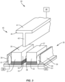
- Figure 3 illustrates a tooling assembly 20 employed to form the stringers 10.
- the tooling assembly 20 generally includes a die assembly 30 and a punch assembly 40.
- the die assembly 30 includes a pair of form blocks 31, 32 that are spaced apart to form a die cavity 33.
- the form blocks 31, 32 can be constructed from relatively rigid material, such as but not limited to wood, metal, ceramic or a composite.
- the first form block 31 includes an inner surface 34 and an upper surface 35.
- the second form block 32 includes an inner surface 36 and an upper surface 37.
- the form blocks 31, 32 can include inside radii between the inner surfaces 34, 36 and the upper surfaces 35, 37 that provides for a smooth transition of the charges 9a, 9b between the blade section 11 and the flange section 12.
- a pair of L-shape, elongated brackets 38, 39 is mounted on a plate 60 on opposite sides of form blocks 31, 32.
- the brackets 38, 39 retain the form blocks 31, 32 on the plate 60 as well as react lateral forming forces generated by the form blocks 31, 32.
- One or more actuators 89 can move the form blocks 31, 32 to adjust a width of the die cavity 33.
- Inflatable bladders 61 can be positioned between the form blocks 31, 32 and the brackets 38, 39.
- the bladders 61 can be adjusted in size by the actuators 89 to control the position of the form blocks 31, 32.
- the bladders 61 can also provide for adjustable pressure to control the movement and forces on the form blocks 31, 32.
- the forms blocks 31, 32 can also be connected to one or more mechanical devices that move and apply adjustable pressure on the forms blocks 31, 32.
- the punch assembly 40 includes a punch die 41.
- the punch die 41 includes a first section 42 sized to fit within the die cavity 33 and a second section 43 providing the punch die 41 with a sectional shape that resembles the letter T.
- the transitions between the first section 42 and second section 43 can include various curvatures to form smooth transitions on the stringer 10 between the blade section 11 and the flange section 12.
- One or more actuators 49 are configured to power the punch die 41 into and out of the die cavity 33.
- the charges 9a, 9b are tensioned along their length during the punching process.
- the amount of tensioning in the different charges 9a, 9b can be the same or different. This allows independent fiber movement within the different charges 9a, 9b and different sections of the stringer 10. This can reduce wrinkles in the charges 9a, 9b during the forming process which could result in disposing of the stringer 10 and/or requiring repair.
- Figures 4-11 illustrate a method of forming a stringer 10 with separately tensioned charges 9a, 9b.
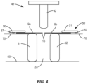
- Figure 4 illustrates the charges 9a, 9b placed over the form blocks 31, 32.
- a first section of the charges 9a, 9b including the first ends 16 extend over the die cavity 33.
- a second section of the charges 9a, 9b are positioned over support members 70 that are located in proximity to the form blocks 31, 32.
- Holding members 50 secure the charges 9a, 9b to the support members 70.
- the holding members 50 are plates 51 sized and shaped to contact and apply a force to secure the charges 9a, 9b against the support member 70.
- the holding member 50 can include a clamp 52 that applies an additional force to secure the plate 51 to the charges 9a, 9b.
- Mechanical fasteners can also extend between the plate 51 and support member 70 to secure the charges 9a, 9b.
- the holding members 50 can also include a grip surface 57 to control movement of the charges 9a, 9b.
- the grip surface 57 can include surface configurations including but not limited to knurling, etching, and bossing.
- Each of the holding members 50 can also include an inflatable bladder 53 as illustrated in Figure 6 .
- the bladders 53 are disposed at the support member 70 and can be formed of various suitable materials capable of being pressurized and inflated to the required degree using, for example, pneumatic pressure.
- the positioning can include being over the support 70 and a second end 17 of the charges 9a, 9b.
- An actuator 54 can control fluid that is moved to and from a reservoir to inflate and deflate the bladders 53 as necessary to control the pinch force.
- the holding members 50 secure the charges 9a, 9b to the support members 70 to allow tensioning of the charges 9a, 9b during the punching process.
- the holding members 50 contact the charges 9a, 9b at the second ends 17. This provides for the charges 9a, 9b to be tensioned along their lengths measured between the first and second ends 16, 17.
- the charges 9a, 9b extend outward from the form blocks 31, 32 with the first ends 16 positioned over the die cavity 33.
- the first ends 16 can be spaced apart as illustrated in Figure 4 , in abutting contact with one another, or can overlap.
- the punch die 41 can be raised upward away from the charges 9a, 9b.
- the holding members 50 apply a force B that secures the charges 9a, 9b against the support members 70.
- the punch die 41 begins the punching process and is brought downward in the direction of arrow A.
- the punching process continues with the punch die 41 moving farther in the direction of arrow A and into the die cavity 33 as illustrated in Figure 8 .
- This movement forces the first ends 16 and adjacent sections of the charges 9a, 9b into the die cavity 33.
- the charges 9a, 9b are tensioned during the punching process because the holding members 50 maintain the position of the charges 9a, 9b on the support members 70 as the first ends 16 and adjacent sections are forced into the die cavity 33.
- the first sections that are driven into the die cavity 33 form the blades 11a, 11b of each of the charges 9a, 9b.
- the second sections that remain out of the die cavity 33 form the flanges 12a, 12b.
- the punch die 41 can include a surface configured to provide friction to create a tension state within the charges 9a, 9b as the punch 41 is being moved into the die cavity 33.
- the punch die 41 can be constructed from a material or be coated with a material that provides for the tensioning. This can also include surface configurations including but not limited to knurling, etching, and embossing.
- release film 56 can be positioned between the punch die 41 and the charges 9a, 9b as illustrated in Figure 9 .
- the release film 56 can be constructed from material that provides for contact and tensioning with the charges 9a, 9b and prevents adherence of the first and second charges 9a, 9b to the punch die 41.
- the release film 56 can be constructed from a variety of materials, including but not limited to Teflon.
- the release film 56 can be sized to extend over the entirety or limited sections of the punch die 41.
- the punch die 41 can be inserted various depths into the die cavity 33. This can include the second section 43 contacting against the sections of the charges 9a, 9b that remain out of the die cavity 33. This contact can provide a forming force to shape the flanges 12a, 12b. Other methods can include a lesser amount of insertion into the die cavity 33 with the second section 43 remaining spaced away from the flanges 12a, 12b.
- the charges 9a, 9b are independently tensioned during the forming process. This tensioning minimizes wrinkling of the charges 9a, 9b as the charges 9a, 9b can move independently of one another during formation. The individual movement facilitates formation of stringers 10 that are not geometrically symmetric and/or constructed from different materials. The charges 9a, 9b can be individually tensioned to obtain the desired contour of the stringer 10.
- the punch die 41 is removed from the die cavity 33. As illustrated in Figure 10 , the punch die 41 is moved in the direction of arrow C away from the die cavity 33 and out of contact with the charges 9a, 9b.
- the form blocks 31, 32 are moved inward towards one another in the direction of arrows D.
- This movement of the form blocks 31, 32 can apply a lateral force and join the blades 11a, 11b together.
- the holding members 50 can remain in contact with the charges 9a, 9b as the form blocks 31, 32 move towards one another.
- the movement of the form blocks 31, 32 pulls the charges 9a, 9b out of contact with the holding members 50.
- the holding members 50 remain in contact after the form blocks 31, 32 have completed their inward movement.
- the holding members 50 can also be removed from the charges 9a, 9b prior to movement of the form blocks 31, 32.
- the formed stringer 10 that includes the first and second charges 9a, 9b can then be cured. This can include moving the formed stringer 10 into a cure tool. As illustrated in Figure 11 , the stringer 10 can remain between the form blocks 31, 32 which acts as the cure tool. A composite filler material 15 can be placed into the groove formed between the charges 9a, 9b as illustrated in Figure 12 .
- the stringer 10 can be installed in a vacuum bag assembly and cured.
- the stringer 10 disclosed above is referred to as a blade stringer 10.
- the process of tensioning charges 9a, 9b can also be used stringer geometry including but not limited to trapezoidal, hemispherical, and rounded shapes.
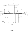
- Figures 13 and 14 illustrate fabrication of a hat stringer 10.
- the die cavity 33 is formed within a die block 80.
- the die block 80 includes top surfaces that form support members 70 for the first and second charges 9a, 9b.
- Holding members 50 are positioned at each of the support members 70 to secure the second ends 17 of the charges 9a, 9b.
- the charges 9a, 9b are each positioned on the support members 70 with a first section that extends outward and over the die cavity 33.
- the charges 9a, 9b are positioned in an overlapping orientation over the die cavity 33 with one of the charges 9a, 9b extending over the other.
- the overlap prior to forming allows for sufficient length of charge 9a and 9b to completely form the hat stringer. As will be described in detail below, the overlap will be eliminated and form a joint between the charges 9a, 9b when forming is complete.
- Figure 13 includes the specific orientation of the first charge 9a positioned over the second charge 9b.
- the punch die 41 is shaped to conform to the shape of the die cavity 33. As illustrated in Figure 14 , the punch die 41 is lowered into the die cavity 33 with the first section 42 of the punch die 41 contacting against and driving the charges 9a, 9b into the die cavity 33. While the charges 9a, 9b are being formed into the die cavity 33, the holding members 50 secure the second sections of the charges 9a, 9b to the support members 70. This results in the charges 9a, 9b being tensioned along their lengths.
- the punch die 41 can extend into the die cavity 33 an amount for the second section 43 to contact against and charges 9a, 9b over to be spaced away from the charges 9a, 9b as illustrated in Figure 14 .
- the punch die 41 is moved away from the die cavity 33.
- the holding members 50 are released from the flanges 12a, 12b and the formed stringer 10 can be removed from the die body 80.
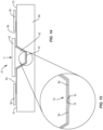
- a scarf joint 19 can be formed between the charges 9a, 9b as illustrated in Figure 15 .
- Each of the charges 9a, 9b is a laminate with multiple plies and having ply drops with offsetting tapers at the first ends 16. These first ends 16 are mated together during the forming process.
- Various other joints can also be formed with the overlapping configuration, including but not limited to an overlap joint and a butt joint.
- the charges 9a, 9b can then be cured either while within the die cavity 33 or after removal from the die cavity 33.
- Figure 16 includes a flowchart of the steps of fabricating a stringer 10.
- the process includes positioning first and second charges 9a, 9b with first ends 16 extending over the die cavity 33 (block 200). This can include positioning the charges over a die cavity 33 formed between first and second form blocks 31, 32, or over a die cavity formed in a die body 80.
- the second ends 17 of the first and second charges 9a, 9b are secured (block 202).
- the second ends 17 are positioned away from the die cavity 33.
- a punch die 41 is inserted into the die cavity 33 (block 204).
- the punch die 41 drives the first ends 16 of the first and second charges 9a, 9b into the die cavity 33 while the second ends 17 remain secured away from the die cavity 33. Moving the punch die 41 and securing of the second ends 17 tensions the charges 9a, 9b along their length between the first and second ends 16, 17.
- the punch die 41 can then be removed from the die cavity 33 (block 206).
- the charges 9a, 9b are tensioned along their lengths.
- the amount of tensioning of each of the charges 9a, 9b can be the same or can be different. With similar charges 9a, 9b having the same construction and geometry, the tensioning can be equal. Differences in tensioning can be caused by charges 9a, 9b with different constructions and/or different geometries such as thickness. Different tensioning can also be caused by the contour of the stringer 10.
- the charges 9a, 9b Prior to inserting the punch die 41, the charges 9a, 9b can be heated. This can include positioning a heating blanket 81 loaded onto the charges 9a, 9b as illustrated in Figure 17 .
- the heating blanket 81 heats the charges 9a, 9b which can soften the charge thermoset or the thermoplastic resin which can facilitate forming the charges 9a, 9b.
- Other heating methods include exposure to radiant or inductive type heaters. Heating can increase the tensioning state with the punch die 41.
- the stringers 10 and fabrication methodologies can being used in a variety of potential applications, particularly in the transportation industry, including for example, aerospace, marine, automotive applications and other application where automated layup equipment can be used.
- the stringers 10 and methodologies can be used in the context of an aircraft manufacturing and service method 236 as illustrated in Figure 18 and a vehicle 238 such as an aircraft as illustrated in Figure 19 .
- exemplary methods 236 can include specification and design 240 of the vehicle 238 and material procurement 242.
- component and subassembly manufacturing 244 and system integration 246 of the vehicle 238 takes place. Thereafter, the vehicle 238 can go through certification and delivery 248 in order to be placed in service 250.
- the vehicle 238 is scheduled for routine maintenance and service 250, which can also include modification, reconfiguration, refurbishment, and so on.
- a system integrator can include without limitation any number of aircraft manufacturers and major-system subcontractors; a third party can include without limitation any number of vendors, subcontractors, and suppliers; and an operator can be an airline, leasing company, military entity, service organization, and so on.
- the vehicle 238 such as an aircraft produced by exemplary method 236 can include an airframe 254 with a plurality of systems 256 and an interior 258.
- high-level systems 256 include one or more of a propulsion system 260, an electrical system 262, a hydraulic system 264, and an environmental system 266. Any number of other systems can be included.
- an aerospace example is shown, the principles of the disclosure can be applied to other industries, such as the marine and automotive industries.
- Systems and methods embodied herein can be employed during any one or more of the stages of the production and service method 236.
- components or subassemblies corresponding to production process 244 can be fabricated or manufactured in a manner similar to components or subassemblies produced while the aircraft 238 is in service.
- one or more apparatus embodiments, method embodiments, or a combination thereof can be utilized during the production stages 244 and 246, for example, by substantially expediting assembly of or reducing the cost of an aircraft 238.
- apparatus embodiments, method embodiments, or a combination thereof can be utilized while the aircraft 238 is in service, for example and without limitation, to maintenance and service 252.
- the stringer 10 can be used to support different structural elements, including but not limited to a wing, airframe, fuselage, and stiffening panels of a vehicle.
- the stringer 10 can be used with a variety of vehicles.
- One vehicle includes a commercial aircraft that includes rows of seats each configured to accommodate a passenger.
- Other vehicles include but are not limited to manned aircraft, unmanned aircraft, manned spacecraft, unmanned spacecraft, manned rotorcraft, unmanned rotorcraft, satellites, rockets, missiles, manned terrestrial vehicles, unmanned terrestrial vehicles, manned surface water borne vehicles, unmanned surface water borne vehicles, manned sub-surface water borne vehicles, unmanned sub-surface water borne vehicles, and combinations thereof.
Landscapes
- Engineering & Computer Science (AREA)
- Mechanical Engineering (AREA)
- Chemical & Material Sciences (AREA)
- Composite Materials (AREA)
- Aviation & Aerospace Engineering (AREA)
- Manufacturing & Machinery (AREA)
- Transportation (AREA)
- Moulding By Coating Moulds (AREA)
- Casting Or Compression Moulding Of Plastics Or The Like (AREA)
Claims (15)
- Verfahren zur Herstellung eines Verbundwerkstoffstringers (10) für ein Fahrzeug (238), wobei das Verfahren aufweist:Positionieren einer ersten und einer zweiten Lage (9a, 9b) in einer Matrizenhöhlung (33), wobei erste Enden (16) jeder der ersten und zweiten Lagen (9a, 9b) über die Matrizenhöhlung (33) hinausragen, wobei die erste Lage (9a) ein Blatt (11a) und einen Flansch (12a) und die zweite Lage (9b) ein Blatt (11b) und einen Flansch (12b) aufweist;Sichern der zweiten Enden (17) jeder der ersten und zweiten Lagen (9a, 9b) entfernt von der Matrizenhöhlung (33);Einfügen eines Stempelwerkzeugs (41) in die Matrizenhöhlung (33) und Einpressen der ersten Enden (16) jeder der ersten und zweiten Lagen (9a, 9b) in die Matrizenhöhlung (33), während die zweiten Enden (17) gesichert außerhalb der Matrizenhöhlung (33) bleiben, wobei das Stempelwerkzeug (41) einen ersten Abschnitt (42) aufweist, der so bemessen ist, dass er in die Matrizenhöhlung (33) passt, und einen zweiten Abschnitt (43) aufweist, der dem Stempelwerkzeug (41) eine Querschnittsform verleiht, die dem Buchstaben T ähnelt, wobei das Stempelwerkzeug (41) so geformt ist, dass es der Form der Matrizenhöhlung (33) entspricht und in die Matrizenhöhlung (33) abgesenkt wird, wobei der erste Abschnitt (42) des Stempelwerkzeugs (41) gegen die Lagen (9a, 9b) anliegt und diese in die Matrizenhöhlung (33) treibt;Bewegen des Stempelwerkzeugs (41) aus der Matrizenhöhlung (33);Zusammenführen der ersten und zweiten Formblöcke (31, 32), die die Matrizenhöhlung (33) bilden, und Anwenden einer seitlichen Kraft auf die Blätter (11a, 11b) der ersten und zweiten Lagen (9a, 9b),wobei das Sichern der zweiten Enden (17) jeder der ersten und zweiten Lagen (9a, 9b) entfernt von der Matrizenhöhlung (33) das Zusammendrücken jedes zweiten Endes (17) zwischen einem Stützelement (70), das sich in der Nähe des Formblocks (31, 32) befindet, und einem Halteelement (50), das eine Platte (51) ist, die so bemessen und geformt ist, dass sie in Kontakt tritt und eine Kraft aufbringt, um die Lage (9a, 9b) gegen das Stützelement (70) zu sichern, aufweist, wobei während des Formgebungsprozesses das Stempelwerkzeug (41) in unterschiedlichen Tiefen in die Höhlung (33) eingeführt wird, wobei der zweite Abschnitt (43) des Stempelwerkzeugs (41) gegen Abschnitte der Lagen (9a, 9b) anliegt, die außerhalb der Matrizenhöhlung (33) verbleiben, oder weniger tiefem Einführen in die Matrizenhöhlung (33), bei dem der zweite Abschnitt (43) des Stempelwerkzeugs (41) von den Flanschen (12a, 12b) beabstandet bleibt.
- Verfahren nach Anspruch 1, des Weiteren mit dem Freigeben der zweiten Enden (17) der ersten und zweiten Lagen (9a, 9b), bevor die ersten und zweiten Formblöcke (31, 32) zusammengeführt werden.
- Verfahren nach einem der Ansprüche 1 bis 2, des Weiteren mit dem Aufblasen eines ersten Blasebalgs (53) und des Befestigens des zweiten Abschnitts der ersten Lage (9a) an einem ersten Stützelement (70) und des Weiteren mit dem Aufblasen eines zweiten Blasebalgs (53) und des Befestigens des zweiten Abschnitts der zweiten Lage (9b) an einem zweiten Stützelement (70).
- Verfahren nach einem der Ansprüche 1 bis 3, des Weiteren mit dem Biegen der ersten und der zweiten Lagen (9a, 9b) in die Matrizenhöhlung (33) und dem Formen von Blättern (11a, 11b) in den ersten und zweiten Lagen (9a, 9b) geformt werden.
- Verfahren nach Anspruch 4, des Weiteren mit dem Halten eines Abschnitts jeder der ersten und der zweiten Lagen (9a, 9b) an den zweiten Enden (17) auf einem Stützelement (70) und dem Formen von Flanschen (12a, 12b) in den ersten und zweiten Lagen (9a, 9b).
- Verfahren nach einem der Ansprüche 1 bis 5, des Weiteren mit dem Spannen der ersten und der zweiten Lagen (9a, 9b) auf unterschiedlichen Spannungsniveaus, indem das Stempelwerkzeug (41) in die Matrizenhöhlung (33) getrieben wird.
- Verfahren nach einem der Ansprüche 1 bis 6, des Weiteren mit dem Überlappen der ersten Enden (16) der ersten und der zweiten Lagen (9a, 9b) über der Matrizenhöhlung (33), bevor das Stempelwerkzeug (41) in die Matrizenhöhlung (33) eingeführt wird.
- Verfahren nach Anspruch 7, des Weiteren mit dem Einführen des Stempelwerkzeugs (41) in die Matrizenhöhlung (33) und Bilden einer Schäftverbindung (19) an den ersten Enden (16) der ersten und der zweiten Lagen (9a, 9b).
- Verfahren nach einem der Ansprüche 1 bis 6, des Weiteren mit dem Aneinanderstoßen der ersten Enden (16) der ersten und der zweiten Lagen (9a, 9b) über der Matrizenhöhlung (33), bevor das Stempelwerkzeug (41) in die Matrizenhöhlung (33) eingeführt wird.
- Verfahren nach Anspruch 1, wobei die Lagen (9a, 9b) vor dem Einführen des Stempelwerkzeugs (41) in die Matrizenhöhlung (33) erhitzt werden.
- Verfahren nach Anspruch 10, des Weiteren mit dem Positionieren zusätzlich einer Heizdecke (81) auf den Lagen (9a, 9b).
- Verfahren nach Anspruch 10, wobei das Erhitzen das Aussetzen zu Strahlung aufweist.
- Verfahren nach Anspruch 10, wobei das Erhitzen mittels Induktionsheizern erfolgt.
- Verfahren zur Herstellung und zum Service eines Fahrzeugs (236), aufweisend:Herstellen eines Verbundwerkstoffstringers (10) für ein Fahrzeug (238) gemäß einem der Ansprüche 1 bis 13;Spezifikation und Design des Fahrzeugs (240);Materialbeschaffung (242);Herstellung von Komponenten und Baugruppen (244);Systemintegration des Fahrzeugs (246);Zertifizierung und Auslieferung des Fahrzeugs (248);Inbetriebnahme des Fahrzeugs (250);Wartung und Service des Fahrzeugs (252).
- Verfahren nach Anspruch 14, wobei die Wartung und der Service des Fahrzeugs (252) Modifikation, Umkonfiguration und Renovierung aufweisen.
Applications Claiming Priority (1)
| Application Number | Priority Date | Filing Date | Title |
|---|---|---|---|
| US15/963,464 US11135789B2 (en) | 2018-04-26 | 2018-04-26 | Methods and devices of forming a tensioned stringer for a vehicle |
Publications (2)
| Publication Number | Publication Date |
|---|---|
| EP3564007A1 EP3564007A1 (de) | 2019-11-06 |
| EP3564007B1 true EP3564007B1 (de) | 2024-10-30 |
Family
ID=65443700
Family Applications (1)
| Application Number | Title | Priority Date | Filing Date |
|---|---|---|---|
| EP19157346.8A Active EP3564007B1 (de) | 2018-04-26 | 2019-02-15 | Verfahren zum bilden eines gespannten längsträgers für ein fahrzeug |
Country Status (3)
| Country | Link |
|---|---|
| US (1) | US11135789B2 (de) |
| EP (1) | EP3564007B1 (de) |
| CN (1) | CN110406082B (de) |
Families Citing this family (6)
| Publication number | Priority date | Publication date | Assignee | Title |
|---|---|---|---|---|
| GB201507519D0 (en) * | 2015-05-01 | 2015-06-17 | Vestas Wind Sys As | Reinforcing Structure for a Wind Turbine Blade |
| US11760041B2 (en) * | 2018-12-10 | 2023-09-19 | Vestas Wind Systems A/S | Wind turbine blade manufacture |
| US11254410B2 (en) * | 2019-12-19 | 2022-02-22 | Spirit Aerosystems, Inc. | Method and apparatus for fabricating reformable stiffening elements |
| PL245780B1 (pl) * | 2020-05-06 | 2024-10-14 | Polskie Zakl Lotnicze Spolka Z Ograniczona Odpowiedzialnoscia | Sposób produkcji profili z materiałów kompozytowych w procesie termoformowania na prasie i w podwyższonej temperaturze, z wykorzystaniem zjawiska odsprężynowania |
| US12017422B2 (en) * | 2022-03-25 | 2024-06-25 | The Boeing Company | Forming a curved, elongate fiber-composite article |
| JP2024113657A (ja) * | 2023-02-09 | 2024-08-22 | ザ・ボーイング・カンパニー | ブレードストリンガ形成方法およびツーリング |
Family Cites Families (26)
| Publication number | Priority date | Publication date | Assignee | Title |
|---|---|---|---|---|
| US2693011A (en) | 1949-03-29 | 1954-11-02 | Fernberg Eric Birger | Metallic fastener for resilient sealing strip |
| DE19832441C1 (de) | 1998-07-18 | 2000-01-05 | Daimler Chrysler Aerospace | Verfahren zur Herstellung einer stringerversteiften Schale in Faserverbundbauweise |
| FR2791919B1 (fr) | 1999-04-12 | 2001-06-01 | Plastic Omnium Cie | Procede de realisation d'une piece en matiere plastique renforcee par surmoulage d'une feuille de renforcement, dispositif pour la mise en oeuvre de ce procede et chaine de fabrication comprenant ce dispositif |
| JP3782072B2 (ja) | 2003-05-30 | 2006-06-07 | 川崎重工業株式会社 | 複合材型材の成形方法及び装置 |
| US8557165B2 (en) | 2008-10-25 | 2013-10-15 | The Boeing Company | Forming highly contoured composite parts |
| US8601694B2 (en) | 2008-06-13 | 2013-12-10 | The Boeing Company | Method for forming and installing stringers |
| US8752293B2 (en) * | 2007-12-07 | 2014-06-17 | The Boeing Company | Method of fabricating structures using composite modules and structures made thereby |
| US8465613B2 (en) | 2011-08-24 | 2013-06-18 | The Boeing Company | Method and apparatus for fabricating variable gauge, contoured composite stiffeners |
| US8551382B2 (en) | 2008-05-28 | 2013-10-08 | The Boeing Company | Modified blade stiffener and fabrication method therefor |
| US9254619B2 (en) | 2008-05-28 | 2016-02-09 | The Boeing Company | Method and apparatus for fabricating variable gauge, contoured composite stiffeners |
| ES2341828B1 (es) | 2008-06-27 | 2011-05-26 | Airbus España, S.L. | Dispositivo y procedimiento para la fabricacion de elementos de material compuesto. |
| JP5378738B2 (ja) * | 2008-09-25 | 2013-12-25 | Jfeスチール株式会社 | 閉構造部材の製造方法、プレス成形装置 |
| US8263205B2 (en) * | 2009-09-17 | 2012-09-11 | Hexcel Corporation | Method of molding complex composite parts using pre-plied multi-directional continuous fiber laminate |
| FR2960470B1 (fr) * | 2010-05-31 | 2014-04-25 | Airbus Operations Sas | Procede de fabrication d'un raidisseur en materiau composite avec une section en omega |
| US9604417B2 (en) | 2011-04-05 | 2017-03-28 | The Boeing Company | Method for making contoured composite stiffeners |
| US9387628B2 (en) | 2011-08-24 | 2016-07-12 | The Boeing Company | Method and apparatus for fabricating composite stringers |
| ES2413189B1 (es) * | 2012-01-10 | 2015-02-11 | Manuel Torres Martínez | Instalacion para fabricar larguerillos de fibra para estructuras aeroespaciales |
| CN104411480B (zh) | 2012-06-29 | 2016-10-05 | 空中客车营运有限公司 | 具有倒圆的腹板端部的t型纵梁及其制造方法 |
| US9162396B2 (en) | 2012-10-12 | 2015-10-20 | The Boeing Company | Method for forming fuselage stringers |
| ES2529601B1 (es) | 2013-07-23 | 2015-10-09 | Manuel Torres Martinez | Molde para fabricar larguerillos de fibra para estructuras aeroespaciales y proceso para fabricar larguerillos de fibra con dicho molde |
| EP2889127B1 (de) | 2013-12-27 | 2020-02-05 | Airbus Operations S.L. | Herstellungsverfahren eines Versteifungselements |
| US9517606B2 (en) | 2014-08-06 | 2016-12-13 | The Boeing Company | Composite structure and method of forming thereof |
| US10369740B2 (en) | 2015-07-09 | 2019-08-06 | The Boeing Company | Method of forming a contoured hat stiffener |
| US10046525B2 (en) | 2016-09-30 | 2018-08-14 | The Boeing Company | Advanced variable radius laminated composite radius filler |
| US10864688B2 (en) | 2018-04-26 | 2020-12-15 | The Boeing Company | Method and apparatus of modular punch forming plates for alignment of a stringer for a vehicle |
| US10780971B2 (en) | 2018-04-26 | 2020-09-22 | The Boeing Company | Methods of manufacturing a panel having a composite stringer for a vehicle |
-
2018
- 2018-04-26 US US15/963,464 patent/US11135789B2/en active Active
-
2019
- 2019-02-15 EP EP19157346.8A patent/EP3564007B1/de active Active
- 2019-04-25 CN CN201910340065.3A patent/CN110406082B/zh active Active
Also Published As
| Publication number | Publication date |
|---|---|
| EP3564007A1 (de) | 2019-11-06 |
| US20190329509A1 (en) | 2019-10-31 |
| CN110406082B (zh) | 2022-06-24 |
| CN110406082A (zh) | 2019-11-05 |
| US11135789B2 (en) | 2021-10-05 |
Similar Documents
| Publication | Publication Date | Title |
|---|---|---|
| EP3564007B1 (de) | Verfahren zum bilden eines gespannten längsträgers für ein fahrzeug | |
| EP2014448B1 (de) | Verfahren und Vorrichtung zur Konturierung von vorimpregnierten Verbundteile | |
| EP3115185B1 (de) | Reduzierung von faltenbildung profilierter, aus einer einzelkompoenentenladung geformter hutversteifer | |
| CN111452947B (zh) | 成形复合桁条 | |
| EP2906412B1 (de) | Verfahren und vorrichtung zur herstellung von faserverbundteilen | |
| EP2561979B1 (de) | Verfahren zur Formung von konturierten Kompositversteifungen | |
| US9254619B2 (en) | Method and apparatus for fabricating variable gauge, contoured composite stiffeners | |
| EP3135462B1 (de) | System und verfahren zur schrittweisen formung eines verbundteils | |
| US9387628B2 (en) | Method and apparatus for fabricating composite stringers | |
| EP3970939B1 (de) | Zwangsformen von konturierten zusammengesetzten hutspanten | |
| EP3388224B1 (de) | System und verfahren zur herstellung einer verbundstruktur | |
| CN110104202B (zh) | 使用铰接式芯轴的复合飞机制造工具 | |
| WO2014200675A1 (en) | Method and apparatus for fabricating composite stringers | |
| CA2926962C (en) | Apparatuses and methods for making reinforcement structures | |
| EP4000722B1 (de) | An die vorformgeometrie angepasster inline-autoklav | |
| EP4000883B1 (de) | Verfahren und system zum bilden einer druckkammer, die durch auflegedorn, autoklav und umfassungsdichtungen definiert ist | |
| US10913221B2 (en) | Shaping a radius filler against a mandrel | |
| HK1127321B (en) | Method and apparatus for contouring composite pre-preg articles | |
| HK1110837A1 (en) | Method and apparatus for forming structural members | |
| HK1110837B (en) | Method and apparatus for forming structural members |
Legal Events
| Date | Code | Title | Description |
|---|---|---|---|
| PUAI | Public reference made under article 153(3) epc to a published international application that has entered the european phase |
Free format text: ORIGINAL CODE: 0009012 |
|
| STAA | Information on the status of an ep patent application or granted ep patent |
Free format text: STATUS: REQUEST FOR EXAMINATION WAS MADE |
|
| 17P | Request for examination filed |
Effective date: 20190215 |
|
| AK | Designated contracting states |
Kind code of ref document: A1 Designated state(s): AL AT BE BG CH CY CZ DE DK EE ES FI FR GB GR HR HU IE IS IT LI LT LU LV MC MK MT NL NO PL PT RO RS SE SI SK SM TR |
|
| AX | Request for extension of the european patent |
Extension state: BA ME |
|
| STAA | Information on the status of an ep patent application or granted ep patent |
Free format text: STATUS: EXAMINATION IS IN PROGRESS |
|
| 17Q | First examination report despatched |
Effective date: 20191114 |
|
| RAP3 | Party data changed (applicant data changed or rights of an application transferred) |
Owner name: THE BOEING COMPANY |
|
| GRAP | Despatch of communication of intention to grant a patent |
Free format text: ORIGINAL CODE: EPIDOSNIGR1 |
|
| STAA | Information on the status of an ep patent application or granted ep patent |
Free format text: STATUS: GRANT OF PATENT IS INTENDED |
|
| RIC1 | Information provided on ipc code assigned before grant |
Ipc: B29C 53/36 20060101ALN20240625BHEP Ipc: B64C 3/18 20060101ALI20240625BHEP Ipc: B29C 53/04 20060101AFI20240625BHEP |
|
| INTG | Intention to grant announced |
Effective date: 20240710 |
|
| GRAS | Grant fee paid |
Free format text: ORIGINAL CODE: EPIDOSNIGR3 |
|
| GRAA | (expected) grant |
Free format text: ORIGINAL CODE: 0009210 |
|
| STAA | Information on the status of an ep patent application or granted ep patent |
Free format text: STATUS: THE PATENT HAS BEEN GRANTED |
|
| AK | Designated contracting states |
Kind code of ref document: B1 Designated state(s): AL AT BE BG CH CY CZ DE DK EE ES FI FR GB GR HR HU IE IS IT LI LT LU LV MC MK MT NL NO PL PT RO RS SE SI SK SM TR |
|
| REG | Reference to a national code |
Ref country code: GB Ref legal event code: FG4D |
|
| REG | Reference to a national code |
Ref country code: CH Ref legal event code: EP |
|
| P01 | Opt-out of the competence of the unified patent court (upc) registered |
Free format text: CASE NUMBER: APP_53925/2024 Effective date: 20240930 |
|
| REG | Reference to a national code |
Ref country code: DE Ref legal event code: R096 Ref document number: 602019061012 Country of ref document: DE |
|
| REG | Reference to a national code |
Ref country code: IE Ref legal event code: FG4D |
|
| REG | Reference to a national code |
Ref country code: LT Ref legal event code: MG9D |
|
| REG | Reference to a national code |
Ref country code: NL Ref legal event code: MP Effective date: 20241030 |
|
| PG25 | Lapsed in a contracting state [announced via postgrant information from national office to epo] |
Ref country code: HR Free format text: LAPSE BECAUSE OF FAILURE TO SUBMIT A TRANSLATION OF THE DESCRIPTION OR TO PAY THE FEE WITHIN THE PRESCRIBED TIME-LIMIT Effective date: 20241030 Ref country code: IS Free format text: LAPSE BECAUSE OF FAILURE TO SUBMIT A TRANSLATION OF THE DESCRIPTION OR TO PAY THE FEE WITHIN THE PRESCRIBED TIME-LIMIT Effective date: 20250228 Ref country code: PT Free format text: LAPSE BECAUSE OF FAILURE TO SUBMIT A TRANSLATION OF THE DESCRIPTION OR TO PAY THE FEE WITHIN THE PRESCRIBED TIME-LIMIT Effective date: 20250228 |
|
| PGFP | Annual fee paid to national office [announced via postgrant information from national office to epo] |
Ref country code: DE Payment date: 20250227 Year of fee payment: 7 |
|
| PG25 | Lapsed in a contracting state [announced via postgrant information from national office to epo] |
Ref country code: FI Free format text: LAPSE BECAUSE OF FAILURE TO SUBMIT A TRANSLATION OF THE DESCRIPTION OR TO PAY THE FEE WITHIN THE PRESCRIBED TIME-LIMIT Effective date: 20241030 Ref country code: NL Free format text: LAPSE BECAUSE OF FAILURE TO SUBMIT A TRANSLATION OF THE DESCRIPTION OR TO PAY THE FEE WITHIN THE PRESCRIBED TIME-LIMIT Effective date: 20241030 |
|
| REG | Reference to a national code |
Ref country code: AT Ref legal event code: MK05 Ref document number: 1736506 Country of ref document: AT Kind code of ref document: T Effective date: 20241030 |
|
| PG25 | Lapsed in a contracting state [announced via postgrant information from national office to epo] |
Ref country code: BG Free format text: LAPSE BECAUSE OF FAILURE TO SUBMIT A TRANSLATION OF THE DESCRIPTION OR TO PAY THE FEE WITHIN THE PRESCRIBED TIME-LIMIT Effective date: 20241030 |
|
| PG25 | Lapsed in a contracting state [announced via postgrant information from national office to epo] |
Ref country code: ES Free format text: LAPSE BECAUSE OF FAILURE TO SUBMIT A TRANSLATION OF THE DESCRIPTION OR TO PAY THE FEE WITHIN THE PRESCRIBED TIME-LIMIT Effective date: 20241030 |
|
| PG25 | Lapsed in a contracting state [announced via postgrant information from national office to epo] |
Ref country code: NO Free format text: LAPSE BECAUSE OF FAILURE TO SUBMIT A TRANSLATION OF THE DESCRIPTION OR TO PAY THE FEE WITHIN THE PRESCRIBED TIME-LIMIT Effective date: 20250130 |
|
| PG25 | Lapsed in a contracting state [announced via postgrant information from national office to epo] |
Ref country code: LV Free format text: LAPSE BECAUSE OF FAILURE TO SUBMIT A TRANSLATION OF THE DESCRIPTION OR TO PAY THE FEE WITHIN THE PRESCRIBED TIME-LIMIT Effective date: 20241030 Ref country code: GR Free format text: LAPSE BECAUSE OF FAILURE TO SUBMIT A TRANSLATION OF THE DESCRIPTION OR TO PAY THE FEE WITHIN THE PRESCRIBED TIME-LIMIT Effective date: 20250131 Ref country code: AT Free format text: LAPSE BECAUSE OF FAILURE TO SUBMIT A TRANSLATION OF THE DESCRIPTION OR TO PAY THE FEE WITHIN THE PRESCRIBED TIME-LIMIT Effective date: 20241030 |
|
| PG25 | Lapsed in a contracting state [announced via postgrant information from national office to epo] |
Ref country code: PL Free format text: LAPSE BECAUSE OF FAILURE TO SUBMIT A TRANSLATION OF THE DESCRIPTION OR TO PAY THE FEE WITHIN THE PRESCRIBED TIME-LIMIT Effective date: 20241030 |
|
| PGFP | Annual fee paid to national office [announced via postgrant information from national office to epo] |
Ref country code: FR Payment date: 20250225 Year of fee payment: 7 |
|
| PGFP | Annual fee paid to national office [announced via postgrant information from national office to epo] |
Ref country code: GB Payment date: 20250227 Year of fee payment: 7 |
|
| PG25 | Lapsed in a contracting state [announced via postgrant information from national office to epo] |
Ref country code: RS Free format text: LAPSE BECAUSE OF FAILURE TO SUBMIT A TRANSLATION OF THE DESCRIPTION OR TO PAY THE FEE WITHIN THE PRESCRIBED TIME-LIMIT Effective date: 20250130 |
|
| PG25 | Lapsed in a contracting state [announced via postgrant information from national office to epo] |
Ref country code: SM Free format text: LAPSE BECAUSE OF FAILURE TO SUBMIT A TRANSLATION OF THE DESCRIPTION OR TO PAY THE FEE WITHIN THE PRESCRIBED TIME-LIMIT Effective date: 20241030 |
|
| PG25 | Lapsed in a contracting state [announced via postgrant information from national office to epo] |
Ref country code: DK Free format text: LAPSE BECAUSE OF FAILURE TO SUBMIT A TRANSLATION OF THE DESCRIPTION OR TO PAY THE FEE WITHIN THE PRESCRIBED TIME-LIMIT Effective date: 20241030 |
|
| PG25 | Lapsed in a contracting state [announced via postgrant information from national office to epo] |
Ref country code: EE Free format text: LAPSE BECAUSE OF FAILURE TO SUBMIT A TRANSLATION OF THE DESCRIPTION OR TO PAY THE FEE WITHIN THE PRESCRIBED TIME-LIMIT Effective date: 20241030 |
|
| PG25 | Lapsed in a contracting state [announced via postgrant information from national office to epo] |
Ref country code: RO Free format text: LAPSE BECAUSE OF FAILURE TO SUBMIT A TRANSLATION OF THE DESCRIPTION OR TO PAY THE FEE WITHIN THE PRESCRIBED TIME-LIMIT Effective date: 20241030 |
|
| PG25 | Lapsed in a contracting state [announced via postgrant information from national office to epo] |
Ref country code: SK Free format text: LAPSE BECAUSE OF FAILURE TO SUBMIT A TRANSLATION OF THE DESCRIPTION OR TO PAY THE FEE WITHIN THE PRESCRIBED TIME-LIMIT Effective date: 20241030 |
|
| PG25 | Lapsed in a contracting state [announced via postgrant information from national office to epo] |
Ref country code: CZ Free format text: LAPSE BECAUSE OF FAILURE TO SUBMIT A TRANSLATION OF THE DESCRIPTION OR TO PAY THE FEE WITHIN THE PRESCRIBED TIME-LIMIT Effective date: 20241030 |
|
| PG25 | Lapsed in a contracting state [announced via postgrant information from national office to epo] |
Ref country code: IT Free format text: LAPSE BECAUSE OF FAILURE TO SUBMIT A TRANSLATION OF THE DESCRIPTION OR TO PAY THE FEE WITHIN THE PRESCRIBED TIME-LIMIT Effective date: 20241030 |
|
| REG | Reference to a national code |
Ref country code: DE Ref legal event code: R097 Ref document number: 602019061012 Country of ref document: DE |
|
| PLBE | No opposition filed within time limit |
Free format text: ORIGINAL CODE: 0009261 |
|
| STAA | Information on the status of an ep patent application or granted ep patent |
Free format text: STATUS: NO OPPOSITION FILED WITHIN TIME LIMIT |
|
| PG25 | Lapsed in a contracting state [announced via postgrant information from national office to epo] |
Ref country code: SE Free format text: LAPSE BECAUSE OF FAILURE TO SUBMIT A TRANSLATION OF THE DESCRIPTION OR TO PAY THE FEE WITHIN THE PRESCRIBED TIME-LIMIT Effective date: 20241030 |
|
| PG25 | Lapsed in a contracting state [announced via postgrant information from national office to epo] |
Ref country code: MC Free format text: LAPSE BECAUSE OF FAILURE TO SUBMIT A TRANSLATION OF THE DESCRIPTION OR TO PAY THE FEE WITHIN THE PRESCRIBED TIME-LIMIT Effective date: 20241030 |
|
| REG | Reference to a national code |
Ref country code: CH Ref legal event code: PL |
|
| 26N | No opposition filed |
Effective date: 20250731 |
|
| PG25 | Lapsed in a contracting state [announced via postgrant information from national office to epo] |
Ref country code: LU Free format text: LAPSE BECAUSE OF NON-PAYMENT OF DUE FEES Effective date: 20250215 |
|
| PG25 | Lapsed in a contracting state [announced via postgrant information from national office to epo] |
Ref country code: CH Free format text: LAPSE BECAUSE OF NON-PAYMENT OF DUE FEES Effective date: 20250228 |
|
| REG | Reference to a national code |
Ref country code: BE Ref legal event code: MM Effective date: 20250228 |
|
| PG25 | Lapsed in a contracting state [announced via postgrant information from national office to epo] |
Ref country code: BE Free format text: LAPSE BECAUSE OF NON-PAYMENT OF DUE FEES Effective date: 20250228 |
|
| PG25 | Lapsed in a contracting state [announced via postgrant information from national office to epo] |
Ref country code: IE Free format text: LAPSE BECAUSE OF NON-PAYMENT OF DUE FEES Effective date: 20250215 |