EP3563809A1 - Covered stent - Google Patents
Covered stent Download PDFInfo
- Publication number
- EP3563809A1 EP3563809A1 EP17886902.0A EP17886902A EP3563809A1 EP 3563809 A1 EP3563809 A1 EP 3563809A1 EP 17886902 A EP17886902 A EP 17886902A EP 3563809 A1 EP3563809 A1 EP 3563809A1
- Authority
- EP
- European Patent Office
- Prior art keywords
- coating membrane
- coating
- membrane
- covered
- stent
- Prior art date
- Legal status (The legal status is an assumption and is not a legal conclusion. Google has not performed a legal analysis and makes no representation as to the accuracy of the status listed.)
- Granted
Links
Images


Classifications
-
- A—HUMAN NECESSITIES
- A61—MEDICAL OR VETERINARY SCIENCE; HYGIENE
- A61F—FILTERS IMPLANTABLE INTO BLOOD VESSELS; PROSTHESES; DEVICES PROVIDING PATENCY TO, OR PREVENTING COLLAPSING OF, TUBULAR STRUCTURES OF THE BODY, e.g. STENTS; ORTHOPAEDIC, NURSING OR CONTRACEPTIVE DEVICES; FOMENTATION; TREATMENT OR PROTECTION OF EYES OR EARS; BANDAGES, DRESSINGS OR ABSORBENT PADS; FIRST-AID KITS
- A61F2/00—Filters implantable into blood vessels; Prostheses, i.e. artificial substitutes or replacements for parts of the body; Appliances for connecting them with the body; Devices providing patency to, or preventing collapsing of, tubular structures of the body, e.g. stents
- A61F2/82—Devices providing patency to, or preventing collapsing of, tubular structures of the body, e.g. stents
- A61F2/86—Stents in a form characterised by the wire-like elements; Stents in the form characterised by a net-like or mesh-like structure
-
- A—HUMAN NECESSITIES
- A61—MEDICAL OR VETERINARY SCIENCE; HYGIENE
- A61F—FILTERS IMPLANTABLE INTO BLOOD VESSELS; PROSTHESES; DEVICES PROVIDING PATENCY TO, OR PREVENTING COLLAPSING OF, TUBULAR STRUCTURES OF THE BODY, e.g. STENTS; ORTHOPAEDIC, NURSING OR CONTRACEPTIVE DEVICES; FOMENTATION; TREATMENT OR PROTECTION OF EYES OR EARS; BANDAGES, DRESSINGS OR ABSORBENT PADS; FIRST-AID KITS
- A61F2/00—Filters implantable into blood vessels; Prostheses, i.e. artificial substitutes or replacements for parts of the body; Appliances for connecting them with the body; Devices providing patency to, or preventing collapsing of, tubular structures of the body, e.g. stents
- A61F2/02—Prostheses implantable into the body
- A61F2/04—Hollow or tubular parts of organs, e.g. bladders, tracheae, bronchi or bile ducts
- A61F2/06—Blood vessels
- A61F2/07—Stent-grafts
-
- A—HUMAN NECESSITIES
- A61—MEDICAL OR VETERINARY SCIENCE; HYGIENE
- A61F—FILTERS IMPLANTABLE INTO BLOOD VESSELS; PROSTHESES; DEVICES PROVIDING PATENCY TO, OR PREVENTING COLLAPSING OF, TUBULAR STRUCTURES OF THE BODY, e.g. STENTS; ORTHOPAEDIC, NURSING OR CONTRACEPTIVE DEVICES; FOMENTATION; TREATMENT OR PROTECTION OF EYES OR EARS; BANDAGES, DRESSINGS OR ABSORBENT PADS; FIRST-AID KITS
- A61F2/00—Filters implantable into blood vessels; Prostheses, i.e. artificial substitutes or replacements for parts of the body; Appliances for connecting them with the body; Devices providing patency to, or preventing collapsing of, tubular structures of the body, e.g. stents
- A61F2/02—Prostheses implantable into the body
- A61F2/04—Hollow or tubular parts of organs, e.g. bladders, tracheae, bronchi or bile ducts
- A61F2/06—Blood vessels
- A61F2/07—Stent-grafts
- A61F2002/072—Encapsulated stents, e.g. wire or whole stent embedded in lining
-
- A—HUMAN NECESSITIES
- A61—MEDICAL OR VETERINARY SCIENCE; HYGIENE
- A61F—FILTERS IMPLANTABLE INTO BLOOD VESSELS; PROSTHESES; DEVICES PROVIDING PATENCY TO, OR PREVENTING COLLAPSING OF, TUBULAR STRUCTURES OF THE BODY, e.g. STENTS; ORTHOPAEDIC, NURSING OR CONTRACEPTIVE DEVICES; FOMENTATION; TREATMENT OR PROTECTION OF EYES OR EARS; BANDAGES, DRESSINGS OR ABSORBENT PADS; FIRST-AID KITS
- A61F2210/00—Particular material properties of prostheses classified in groups A61F2/00 - A61F2/26 or A61F2/82 or A61F9/00 or A61F11/00 or subgroups thereof
- A61F2210/0014—Particular material properties of prostheses classified in groups A61F2/00 - A61F2/26 or A61F2/82 or A61F9/00 or A61F11/00 or subgroups thereof using shape memory or superelastic materials, e.g. nitinol
-
- A—HUMAN NECESSITIES
- A61—MEDICAL OR VETERINARY SCIENCE; HYGIENE
- A61F—FILTERS IMPLANTABLE INTO BLOOD VESSELS; PROSTHESES; DEVICES PROVIDING PATENCY TO, OR PREVENTING COLLAPSING OF, TUBULAR STRUCTURES OF THE BODY, e.g. STENTS; ORTHOPAEDIC, NURSING OR CONTRACEPTIVE DEVICES; FOMENTATION; TREATMENT OR PROTECTION OF EYES OR EARS; BANDAGES, DRESSINGS OR ABSORBENT PADS; FIRST-AID KITS
- A61F2240/00—Manufacturing or designing of prostheses classified in groups A61F2/00 - A61F2/26 or A61F2/82 or A61F9/00 or A61F11/00 or subgroups thereof
- A61F2240/001—Designing or manufacturing processes
Definitions
- the present application relates to the field of implantable medical devices, and more particularly relates to a covered stent.
- An existing covered stent generally adopts a single-layer coating membrane structure or a two-layer coating membrane structure. After a stent having the single-layer coating membrane structure is implanted into a body, a metal stent would be exposed to blood and may be corroded after long time. The single-layer coating membrane structure is directly adhered and sealed to the inner wall of a blood vessel by the metal stent, causing low sealing property and low biocompatibility.
- both the inner and outer surfaces of the metal stent are covered with membranes, and inner and outer coating membranes and the metal stent are combined into a whole by high-temperature thermal treatment.
- the metal stent avoids being directly exposed to the blood to prevent corrosion of the metal stent and release of metal ions; and furthermore, the proximal end of the stent is directly adhered to the inner wall of the blood vessel by the coating membranes, achieving relatively high sealing property and high biocompatibility.
- the inner and outer coating membranes are combined into a whole by the thermal treatment method, and thus may be torn under long-term impact of the blood on the proximal-end end surface and the distal-end end surface of the covered stent to further cause the exposure of the metal stent to the blood, which accelerates the corrosion of the metal stent to release the metal ions.
- nickel ions released by a metal stent made of a nickel-titanium alloy in the blood have a carcinogenic effect.
- tear openings formed by the tearing of the inner and outer coating membranes on the proximal-end end surface and the distal-end end surface of the covered stent would slow down the blood flow to easily cause thrombosis in the tearing openings, and may increase the impact force of the flowing blood to the covered stent, thereby increasing the risk of stent displacement.
- the present application provides a covered stent capable of avoiding inner and outer coating membranes on the proximal-end end surface and the distal-end end surface from being torn so as to overcome the defects in the prior art.
- a covered stent having a proximal-end end surface, a distal-end end surface and a peripheral surface located between the proximal-end end surface and the distal-end end surface.
- the peripheral surface includes an inner surface and an outer surface opposite to the inner surface.
- the outer surface is covered with a first coating membrane, and the inner surface is covered with a second coating membrane.
- the covered stent further includes a stent main body arranged between the first coating membrane and the second coating membrane. At least one of two ends of the first coating membrane and the second coating membrane are folded inwards or outwards so as to cover at least one of the proximal-end end surface and the distal-end end surface.
- the two ends of the first coating membrane and the second coating membrane are folded towards the inner surface and are connected with the second coating membrane through the stent main body.
- the two ends of the first coating membrane and the second coating membrane are folded towards the outer surface and are connected with the first coating membrane through the stent main body.
- the two ends of the second coating membrane are folded towards the outer surface and are connected with the second coating membrane through the stent main body, and the two ends of the first coating membrane are folded towards the inner surface and are connected with the second coating membrane.
- a membrane covering method of the above-mentioned covered stent including:
- a membrane covering method of the above-mentioned covered stent including:
- a membrane covering method of the above-mentioned covered stent including:
- the prevent application may prevent blood flow from directly impacting the coating membranes on the inner and outer surfaces of the proximal-end end surface and/or the distal-end end surface through a flanging design for the coating membranes on the proximal-end end surface and/or the distal-end end surface of the covered stent, thereby avoiding tearing of the coating membranes of the inner and outer surfaces caused by long-term blood flow impact and a series of adverse effects caused by the tearing of the coating membranes.
- a covered stent 10 is a tubular structure (used for forming a blood flow channel) with openings at two ends, and has a proximal-end end surface 11, a distal-end end surface 12 and a peripheral surface 13 located between the proximal-end end surface 11 and the distal-end end surface 12.
- the peripheral surface 13 includes an outer surface 131 and an inner surface 132 opposite to the outer surface 131.
- the outer surface 131 and the inner surface 132 are respectively located on two sides of a stent main body 15.
- the outer surface 131 is covered with a first coating membrane 141
- the inner surface 132 is covered with a second coating membrane 142.
- the first coating membrane 141 and the second coating membrane 142 have certain thicknesses and are generally made of a biocompatible macromolecular material, such as a PET (polyethylene terephthalate) membrane or PTFE (poly tetra fluoroethylene) membrane.
- the stent main body 15 is arranged between the first coating membrane 141 and the second coating membrane 142.
- the first coating membrane 141 and the second coating membrane 142 are adhered by thermal treatment so as to clamp the stent main body 15 therebetween.
- the stent main body 15 is cut and expanded from a biocompatible plastic expansion material tubular product known in the art, and the tubular product may be medical stainless steel, or a cobalt-nobelium alloy, or a self-expansion material such as a nickel-titanium alloy.
- the stent main body 15 When made of a plastic expansion material, the stent main body 15 may be radially compressed in a delivery sheath tube and may be expanded to an initial shape and size through an inflatable balloon or an equivalent expansion mechanism.
- the stent main body 15 When made of the self-expansion material, the stent main body 15 may be radially compressed in the delivery sheath tube and recovers the initial shape and size in the absence of the compression of the delivery sheath tube.
- the stent main body 15 may be cut from the tube product or woven by a metal wire.
- two ends of the first coating membrane 141 and the second coating membrane 142 are folded inwards (namely inside the lumen of the covered stent) and are connected with the second coating membrane 142 through the stent main body 15 so as to cover the proximal-end end surface 11 and the distal-end end surface 12 of the covered stent 10.
- the present application further provides a manufacturing method of the above-mentioned covered stent 10, including that:
- the prevent application may prevent blood flow from directly impacting the coating membranes on the proximal-end end surface and the distal-end end surface by a flanging design for the coating membranes covering the peripheral surface of the covered stent on the proximal-end end surface and the distal-end end surface of the covered stent, thereby avoiding tearing of the coating membranes on the inner and outer surfaces caused by long-term blood flow impact and a series of adverse effects caused by the tearing of the coating membranes.
- a covered stent 20 is of a tubular structure (used for forming a blood flow channel) with openings in two ends, and has a proximal-end end surface 21, a distal-end end surface 22 and a peripheral surface 23 located between the proximal-end end surface 21 and the distal-end end surface 22.
- the peripheral surface 23 includes an outer surface 231 and an inner surface 232 opposite to the outer surface 231.
- the outer surface 231 is covered with a first coating membrane 241
- the inner surface 232 is covered with a second coating membrane 242.
- the first coating membrane 241 and the second coating membrane 242 have certain thicknesses and are generally made of a biocompatible macromolecular material, such as a PET membrane or PTFE membrane.
- a stent main body 25 is arranged between the first coating membrane 241 and the second coating membrane 242.
- the first coating membrane 241 and the second coating membrane 242 are adhered by thermal treatment so as to clamp the stent main body 25 therebetween.
- the stent main body 25 is cut and expanded from a biocompatible plastic expansion material tubular product known in the art, and the tubular product may be medical stainless steel, or a cobalt-nobelium alloy, or a self-expansion material such as a nickel-titanium alloy.
- the stent main body 25 When made of a plastic expansion material, the stent main body 25 may be radially compressed in a delivery sheath tube and may be expanded to an initial shape and size through an inflatable balloon or an equivalent expansion mechanism. When made of the self-expansion material, the stent main body 25 may be radially compressed in the delivery sheath tube and recovers the initial shape and size in the absence of the compression of the delivery sheath tube.
- the stent main body 25 may be cut from the tube product or woven by a metal wire.
- first coating membrane 241 and the second coating membrane 242 are folded outwards (namely outside the lumen of the covered stent) and are connected with the first coating membrane 241 through the stent main body 25 so as to cover the proximal-end end surface 21 and the distal-end end surface 22 of the covered stent 20.
- the present application further provides a manufacturing method of the above-mentioned covered stent 20, including that:
- a covered stent 30 is of a tubular structure (used for forming a blood flow channel) with openings in two ends, and has a proximal-end end surface 31, a distal-end end surface 32 and a peripheral surface 33 located between the proximal-end end surface 31 and the distal-end end surface 32.
- the peripheral surface 33 includes an outer surface 331 and an inner surface 332 opposite to the outer surface 331.
- the inner surface 332 is covered with a second coating membrane 342. As shown in Fig. 6 , two ends of the second coating membrane 342 are folded outwards (namely towards the outside of the lumen of the covered stent 30). As shown in Fig.
- the outer surface 331 is covered with a first coating membrane 341.
- a first coating membrane 341 As shown in Fig. 8 , two ends of the first coating membrane 341 are folded inwards (namely towards the inside of the lumen of the covered stent 30).
- a stent main body 35 is also arranged between the first coating membrane 341 and the second coating membrane 342.
- the first coating membrane 341 and the second coating membrane 342 are adhered by thermal treatment so as to clamp the stent main body 35 therebetween.
- the present application further provides a manufacturing method of the above-mentioned covered stent 30, including that:
Landscapes
- Health & Medical Sciences (AREA)
- Engineering & Computer Science (AREA)
- Biomedical Technology (AREA)
- Heart & Thoracic Surgery (AREA)
- Public Health (AREA)
- Transplantation (AREA)
- Cardiology (AREA)
- Veterinary Medicine (AREA)
- Oral & Maxillofacial Surgery (AREA)
- Vascular Medicine (AREA)
- Life Sciences & Earth Sciences (AREA)
- Animal Behavior & Ethology (AREA)
- General Health & Medical Sciences (AREA)
- Gastroenterology & Hepatology (AREA)
- Pulmonology (AREA)
- Prostheses (AREA)
- Media Introduction/Drainage Providing Device (AREA)
- Materials For Medical Uses (AREA)
Abstract
Description
- The present application relates to the field of implantable medical devices, and more particularly relates to a covered stent.
- An existing covered stent generally adopts a single-layer coating membrane structure or a two-layer coating membrane structure. After a stent having the single-layer coating membrane structure is implanted into a body, a metal stent would be exposed to blood and may be corroded after long time. The single-layer coating membrane structure is directly adhered and sealed to the inner wall of a blood vessel by the metal stent, causing low sealing property and low biocompatibility.
- In the two-layer coating membrane structure, both the inner and outer surfaces of the metal stent are covered with membranes, and inner and outer coating membranes and the metal stent are combined into a whole by high-temperature thermal treatment. After this two-layer coating membrane structure is implanted into the body, the metal stent avoids being directly exposed to the blood to prevent corrosion of the metal stent and release of metal ions; and furthermore, the proximal end of the stent is directly adhered to the inner wall of the blood vessel by the coating membranes, achieving relatively high sealing property and high biocompatibility.
- However, in the two-layer coating membrane structure, the inner and outer coating membranes are combined into a whole by the thermal treatment method, and thus may be torn under long-term impact of the blood on the proximal-end end surface and the distal-end end surface of the covered stent to further cause the exposure of the metal stent to the blood, which accelerates the corrosion of the metal stent to release the metal ions. Particularly, nickel ions released by a metal stent made of a nickel-titanium alloy in the blood have a carcinogenic effect. In addition, tear openings formed by the tearing of the inner and outer coating membranes on the proximal-end end surface and the distal-end end surface of the covered stent would slow down the blood flow to easily cause thrombosis in the tearing openings, and may increase the impact force of the flowing blood to the covered stent, thereby increasing the risk of stent displacement.
- The present application provides a covered stent capable of avoiding inner and outer coating membranes on the proximal-end end surface and the distal-end end surface from being torn so as to overcome the defects in the prior art.
- One technical solution of the present application adopted to solve the technical problem is as follows: a covered stent, having a proximal-end end surface, a distal-end end surface and a peripheral surface located between the proximal-end end surface and the distal-end end surface. The peripheral surface includes an inner surface and an outer surface opposite to the inner surface. The outer surface is covered with a first coating membrane, and the inner surface is covered with a second coating membrane. The covered stent further includes a stent main body arranged between the first coating membrane and the second coating membrane. At least one of two ends of the first coating membrane and the second coating membrane are folded inwards or outwards so as to cover at least one of the proximal-end end surface and the distal-end end surface.
- In one embodiment of the present application, the two ends of the first coating membrane and the second coating membrane are folded towards the inner surface and are connected with the second coating membrane through the stent main body.
- In one embodiment of the present application, the two ends of the first coating membrane and the second coating membrane are folded towards the outer surface and are connected with the first coating membrane through the stent main body.
- In one embodiment of the present application, the two ends of the second coating membrane are folded towards the outer surface and are connected with the second coating membrane through the stent main body, and the two ends of the first coating membrane are folded towards the inner surface and are connected with the second coating membrane.
- The present application further solves the technical problems as follows: a membrane covering method of the above-mentioned covered stent is provided, including:
- S1, covering the outer surface of the covered stent with a first coating membrane, and covering the inner surface with a second coating membrane;
- S2, thermally treating the covered stent covered with the coating membranes so as to adhere the first coating membrane and the second coating membrane;
- S3, after the coating membranes are cooled, cutting two ends of the first coating membrane and the second coating membrane to required lengths;
- S4, folding the two ends of the first coating membrane and the second coating membrane towards the inner surface; and
- S5, thermally treating the first coating membrane and the second coating membrane which are folded towards the inner surface so as to adhere the folded coating membranes with the second coating membrane.
- Another technical solution that the present application provides is as follows: a membrane covering method of the above-mentioned covered stent is provided, including:
- S1, covering the outer surface of the covered stent with a first coating membrane, and covering the inner surface with a second coating membrane;
- S2, thermally treating the covered stent covered with the coating membranes so as to adhere the first coating membrane and the second coating membrane;
- S3, after the coating membranes are cooled, cutting two ends of the first coating membrane and the second coating membrane to required lengths;
- S4, folding the two ends of the first coating membrane and the second coating membrane towards the outer surface; and
- S5, thermally treating the first coating membrane and the second coating membrane which are folded towards the outer surface so as to adhere the folded coating membranes with the first coating membrane.
- Another technical solution that the present application provides is as follows: a membrane covering method of the above-mentioned covered stent is provided, including:
- S1, covering the inner surface with a second coating membrane, and cutting two ends of the second coating membrane to required lengths;
- S2, folding the two ends of the second coating membrane towards the outer surface;
- S3, thermally treating the covered stent in Step S2 so as to allow the two ends of the second coating membrane to be adhered with the second coating membrane through a stent main body;
- S4, covering the outer surface with a first coating membrane, and cutting two ends of the first coating membrane to required lengths;
- S5, folding the two ends of the first coating membrane towards the inner surface; and
- S6, thermally treating the covered stent in Step S5 so as to allow the two ends of the first coating membrane to be adhered with the second coating membrane.
- The prevent application may prevent blood flow from directly impacting the coating membranes on the inner and outer surfaces of the proximal-end end surface and/or the distal-end end surface through a flanging design for the coating membranes on the proximal-end end surface and/or the distal-end end surface of the covered stent, thereby avoiding tearing of the coating membranes of the inner and outer surfaces caused by long-term blood flow impact and a series of adverse effects caused by the tearing of the coating membranes.
- The present application will be further described below in combination with accompanying drawings and embodiments. In the drawings:
-
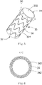
Fig. 1 is a structural schematic diagram of a first embodiment of a covered stent of the present application; -
Fig. 2 is a sectional view along the direction A-A inFig. 1 ; -
Fig. 3 is a structural schematic diagram of a second embodiment of a covered stent of the present application; -
Fig. 4 is a sectional view along the direction B-B inFig. 3 ; -
Fig. 5 is a structural schematic diagram of a covered stent of a third embodiment of the present invention, in which only the inner surface of a stent main body is covered with a second coating membrane; -
Fig. 6 is a sectional view along the direction C-C inFig. 5 ; -
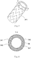
Fig. 7 is a structural schematic diagram of the covered stent of the third embodiment of the present invention, in which both the inner and outer surfaces of the stent main body are covered with coating membranes; and -
Fig. 8 is a sectional view along the direction D-D inFig. 7 . - To understand the technical features, objectives and effects of the present application more clearly, specific implementation modes of the present application are now described in detail in contrast with the accompanying drawings.
- As shown in
Fig. 1 , a coveredstent 10 is a tubular structure (used for forming a blood flow channel) with openings at two ends, and has a proximal-end end surface 11, a distal-end end surface 12 and aperipheral surface 13 located between the proximal-end end surface 11 and the distal-end end surface 12. Theperipheral surface 13 includes anouter surface 131 and aninner surface 132 opposite to theouter surface 131. Theouter surface 131 and theinner surface 132 are respectively located on two sides of a stentmain body 15. In the present embodiment, theouter surface 131 is covered with afirst coating membrane 141, and theinner surface 132 is covered with asecond coating membrane 142. Thefirst coating membrane 141 and thesecond coating membrane 142 have certain thicknesses and are generally made of a biocompatible macromolecular material, such as a PET (polyethylene terephthalate) membrane or PTFE (poly tetra fluoroethylene) membrane. The stentmain body 15 is arranged between thefirst coating membrane 141 and thesecond coating membrane 142. Thefirst coating membrane 141 and thesecond coating membrane 142 are adhered by thermal treatment so as to clamp the stentmain body 15 therebetween. The stentmain body 15 is cut and expanded from a biocompatible plastic expansion material tubular product known in the art, and the tubular product may be medical stainless steel, or a cobalt-nobelium alloy, or a self-expansion material such as a nickel-titanium alloy. When made of a plastic expansion material, the stentmain body 15 may be radially compressed in a delivery sheath tube and may be expanded to an initial shape and size through an inflatable balloon or an equivalent expansion mechanism. When made of the self-expansion material, the stentmain body 15 may be radially compressed in the delivery sheath tube and recovers the initial shape and size in the absence of the compression of the delivery sheath tube. The stentmain body 15 may be cut from the tube product or woven by a metal wire. - As shown in
Fig. 2 , two ends of thefirst coating membrane 141 and thesecond coating membrane 142 are folded inwards (namely inside the lumen of the covered stent) and are connected with thesecond coating membrane 142 through the stentmain body 15 so as to cover the proximal-end end surface 11 and the distal-end end surface 12 of the coveredstent 10. - The present application further provides a manufacturing method of the above-mentioned covered
stent 10, including that: - S1, an
outer surface 131 of a stentmain body 15 is covered with afirst coating membrane 141, and aninner surface 132 is covered with asecond coating membrane 142; - S2, the covered
stent 10 covered with the above-mentioned coating membranes is thermally treated so as to adhere thefirst coating membrane 141 and thesecond coating membrane 142; - S3, after the coating membranes are cooled, two ends of the
first coating membrane 141 and thesecond coating membrane 142 are cut to required lengths; - S4, the two ends of the
first coating membrane 141 and thesecond coating membrane 142 are folded towards theinner surface 132; and - S5, the
first coating membrane 141 and thesecond coating membrane 142 which are folded towards theinner surface 132 are thermally treated so as to adhere the folded coating membranes with thesecond coating membrane 142. Thefirst coating membrane 141 and thesecond coating membrane 142 may be ironed into a whole by using soldering iron after being folded inwards, or the coveredstent 10 may be thermally treated again by using a thermal treatment furnace after thefirst coating membrane 141 and thesecond coating membrane 142 are folded inwards. - The prevent application may prevent blood flow from directly impacting the coating membranes on the proximal-end end surface and the distal-end end surface by a flanging design for the coating membranes covering the peripheral surface of the covered stent on the proximal-end end surface and the distal-end end surface of the covered stent, thereby avoiding tearing of the coating membranes on the inner and outer surfaces caused by long-term blood flow impact and a series of adverse effects caused by the tearing of the coating membranes.
- As shown in
Fig. 3 , a coveredstent 20 is of a tubular structure (used for forming a blood flow channel) with openings in two ends, and has a proximal-end end surface 21, a distal-end end surface 22 and aperipheral surface 23 located between the proximal-end end surface 21 and the distal-end end surface 22. Theperipheral surface 23 includes anouter surface 231 and aninner surface 232 opposite to theouter surface 231. In the present embodiment, theouter surface 231 is covered with afirst coating membrane 241, and theinner surface 232 is covered with asecond coating membrane 242. Thefirst coating membrane 241 and thesecond coating membrane 242 have certain thicknesses and are generally made of a biocompatible macromolecular material, such as a PET membrane or PTFE membrane. A stentmain body 25 is arranged between thefirst coating membrane 241 and thesecond coating membrane 242. Thefirst coating membrane 241 and thesecond coating membrane 242 are adhered by thermal treatment so as to clamp the stentmain body 25 therebetween. The stentmain body 25 is cut and expanded from a biocompatible plastic expansion material tubular product known in the art, and the tubular product may be medical stainless steel, or a cobalt-nobelium alloy, or a self-expansion material such as a nickel-titanium alloy. When made of a plastic expansion material, the stentmain body 25 may be radially compressed in a delivery sheath tube and may be expanded to an initial shape and size through an inflatable balloon or an equivalent expansion mechanism. When made of the self-expansion material, the stentmain body 25 may be radially compressed in the delivery sheath tube and recovers the initial shape and size in the absence of the compression of the delivery sheath tube. The stentmain body 25 may be cut from the tube product or woven by a metal wire. - As shown in
Fig. 4 , two ends of thefirst coating membrane 241 and thesecond coating membrane 242 are folded outwards (namely outside the lumen of the covered stent) and are connected with thefirst coating membrane 241 through the stentmain body 25 so as to cover the proximal-end end surface 21 and the distal-end end surface 22 of the coveredstent 20. - The present application further provides a manufacturing method of the above-mentioned covered
stent 20, including that: - S1, an
outer surface 231 of a stentmain body 25 is covered with afirst coating membrane 241, and aninner surface 232 is covered with asecond coating membrane 242; - S2, the covered
stent 20 covered with the above-mentioned coating membranes is thermally treated so as to adhere thefirst coating membrane 241 and thesecond coating membrane 242; - S3, after the coating membranes are cooled, two ends of the
first coating membrane 241 and thesecond coating membrane 242 are cut to required lengths; - S4, the two ends of the
first coating membrane 241 and thesecond coating membrane 242 are folded towards theouter surface 231; and - S5, the
first coating membrane 241 and thesecond coating membrane 242 which are folded towards theouter surface 231 are thermally treated so as to adhere the folded coating membranes with thefirst coating membrane 241. Thefirst coating membrane 241 and thesecond coating membrane 242 may be ironed into a whole by using soldering iron after being overall inwards folded, or the coveredstent 20 may be thermally treated again by using a thermal treatment furnace after thefirst coating membrane 241 and thesecond coating membrane 242 are folded inwards. - As shown in
Fig. 5 , a coveredstent 30 is of a tubular structure (used for forming a blood flow channel) with openings in two ends, and has a proximal-end end surface 31, a distal-end end surface 32 and aperipheral surface 33 located between the proximal-end end surface 31 and the distal-end end surface 32. Theperipheral surface 33 includes anouter surface 331 and aninner surface 332 opposite to theouter surface 331. Theinner surface 332 is covered with asecond coating membrane 342. As shown inFig. 6 , two ends of thesecond coating membrane 342 are folded outwards (namely towards the outside of the lumen of the covered stent 30). As shown inFig. 7 , theouter surface 331 is covered with afirst coating membrane 341. As shown inFig. 8 , two ends of thefirst coating membrane 341 are folded inwards (namely towards the inside of the lumen of the covered stent 30). A stentmain body 35 is also arranged between thefirst coating membrane 341 and thesecond coating membrane 342. Thefirst coating membrane 341 and thesecond coating membrane 342 are adhered by thermal treatment so as to clamp the stentmain body 35 therebetween. - The present application further provides a manufacturing method of the above-mentioned covered
stent 30, including that: - S1, an
inner surface 332 is covered with asecond coating membrane 342, and two ends of thesecond coating membrane 342 are cut to required lengths; - S2, the two ends of the
second coating membrane 342 are folded towards anouter surface 331; S3, the covered stent in Step S2 is thermally treated so as to allow the two ends of thesecond coating membrane 342 to be adhered with thesecond coating membrane 342 through a gap of a stentmain body 35; - S4, an
outer surface 331 is covered with afirst coating membrane 341, and two ends of thefirst coating membrane 341 are cut to required lengths; - S5, the two ends of the
first coating membrane 341 are folded towards theinner surface 332; and - S6, the covered
stent 30 in Step S5 is thermally treated so as to allow the two ends of thefirst coating membrane 341 to be adhered with thesecond coating membrane 342. - The above-mentioned embodiments are merely expressive of several implementation modes of the present application, and their descriptions are relatively specific and detailed, but are not to be interpreted as limitations to the scope of the patent for invention. It should be noted that persons of ordinary skill in the art can further make a any number of changes and improvements without departing from the scope of the present application, and these changes and improvements shall all fall within the protection scope of the present application. Therefore, the protection scope of the patent of the present application shall be based on attached claims.
Claims (7)
- A covered stent, comprising: a proximal-end end surface, a distal-end end surface and a peripheral surface located between the proximal-end end surface and the distal-end end surface, the peripheral surface comprising an inner surface and an outer surface opposite to the inner surface; the outer surface is covered with a first coating membrane, and the inner surface is covered with a second coating membrane; the covered stent further comprising a stent main body arranged between the first coating membrane and the second coating membrane; wherein at least one of two ends of the first coating membrane and the second coating membrane are folded one of inwards or outwards so as to cover at least one of the proximal-end end surface and the distal-end end surface.
- The covered stent according to claim 1, wherein the two ends of the first coating membrane and the second coating membrane are folded towards the inner surface and are connected with the second coating membrane through the stent main body.
- The covered stent according to claim 1, wherein the two ends of the first coating membrane and the second coating membrane are folded towards the outer surface and are connected with the first coating membrane through the stent main body.
- The covered stent according to claim 1, wherein the two ends of the second coating membrane are folded towards the outer surface and are connected with the second coating membrane through the stent main body, and the two ends of the first coating membrane are folded towards the inner surface and are connected with the second coating membrane.
- A membrane covering method of the covered stent according to claim 2, comprising:S1, covering the outer surface of the covered stent with a first coating membrane, and covering the inner surface with a second coating membrane;S2, thermally treating the covered stent covered with the coating membranes so as to adhere the first coating membrane and the second coating membrane;S3, after the coating membranes are cooled, cutting two ends of the first coating membrane and the second coating membrane to required lengths;S4, folding the two ends of the first coating membrane and the second coating membrane towards the inner surface; andS5, thermally treating the first coating membrane and the second coating membrane which are folded towards the inner surface so as to adhere the folded coating membranes with the second coating membrane.
- A membrane covering method of the covered stent according to claim 3, comprising:S1, covering the outer surface of the covered stent with a first coating membrane, and covering the inner surface with a second coating membrane;S2, thermally treating the covered stent covered with the coating membranes so as to adhere the first coating membrane and the second coating membrane;S3, after the coating membranes are cooled, cutting two ends of the first coating membrane and the second coating membrane to required lengths;S4, overall folding the two ends of the first coating membrane and the second coating membrane towards the outer surface; andS5, thermally treating the first coating membrane and the second coating membrane which are folded towards the outer surface so as to adhere the folded coating membranes with the first coating membrane.
- A membrane covering method of the covered stent according to claim 4, comprising:S1, covering the inner surface with a second coating membrane, and cutting two ends of the second coating membrane to required lengths;S2, folding the two ends of the second coating membrane towards the outer surface;S3, thermally treating the covered stent in Step S2 so as to allow the two ends of the second coating membrane to be adhered with the second coating membrane;S4, covering the outer surface with a first coating membrane, and cutting two ends of the first coating membrane to required lengths;S5, folding the two ends of the first coating membrane towards the inner surface; andS6, thermally treating the covered stent in Step S5 so as to allow the two ends of the first coating membrane to be adhered with the second coating membrane.
Applications Claiming Priority (2)
| Application Number | Priority Date | Filing Date | Title |
|---|---|---|---|
| CN201611238491.9A CN108245278B (en) | 2016-12-28 | 2016-12-28 | stent graft |
| PCT/CN2017/117298 WO2018121364A1 (en) | 2016-12-28 | 2017-12-19 | Covered stent |
Publications (3)
| Publication Number | Publication Date |
|---|---|
| EP3563809A1 true EP3563809A1 (en) | 2019-11-06 |
| EP3563809A4 EP3563809A4 (en) | 2020-11-04 |
| EP3563809B1 EP3563809B1 (en) | 2024-11-27 |
Family
ID=62711082
Family Applications (1)
| Application Number | Title | Priority Date | Filing Date |
|---|---|---|---|
| EP17886902.0A Active EP3563809B1 (en) | 2016-12-28 | 2017-12-19 | Covered stent |
Country Status (4)
| Country | Link |
|---|---|
| US (2) | US11273061B2 (en) |
| EP (1) | EP3563809B1 (en) |
| CN (2) | CN108245278B (en) |
| WO (1) | WO2018121364A1 (en) |
Cited By (1)
| Publication number | Priority date | Publication date | Assignee | Title |
|---|---|---|---|---|
| US11819429B2 (en) * | 2018-03-14 | 2023-11-21 | Bentley Innomed Gmbh | Double stent |
Families Citing this family (9)
| Publication number | Priority date | Publication date | Assignee | Title |
|---|---|---|---|---|
| CN108245278B (en) * | 2016-12-28 | 2020-12-18 | 先健科技(深圳)有限公司 | stent graft |
| CN110833469B (en) * | 2018-08-17 | 2023-06-20 | 先健科技(深圳)有限公司 | Tectorial membrane support |
| CN114533338B (en) * | 2020-11-26 | 2025-09-16 | 先健科技(深圳)有限公司 | Stent graft |
| CN114642527B (en) * | 2020-12-18 | 2025-09-16 | 先健科技(深圳)有限公司 | Tectorial membrane bracket and manufacturing method thereof |
| CN114642526B (en) * | 2020-12-18 | 2026-03-31 | 先健科技(深圳)有限公司 | Covered stent |
| CN115700110A (en) * | 2021-07-30 | 2023-02-07 | 先健科技(深圳)有限公司 | Intestinal stent and intestinal stent assembly with inner and outer double-layer tectorial membrane |
| CN115700111A (en) * | 2021-07-30 | 2023-02-07 | 先健科技(深圳)有限公司 | Intestinal tract stent and intestinal tract stent component |
| CN115517820B (en) * | 2022-05-13 | 2026-02-10 | 科凯(南通)生命科学有限公司 | Transapical mitral valve replacement device |
| CN115919504B (en) * | 2023-02-23 | 2023-05-23 | 杭州唯强医疗科技有限公司 | Split type single embedded branch tectorial membrane support |
Family Cites Families (21)
| Publication number | Priority date | Publication date | Assignee | Title |
|---|---|---|---|---|
| WO1995029647A2 (en) | 1994-04-29 | 1995-11-09 | Scimed Life Systems, Inc. | Stent with collagen |
| EP1704835B1 (en) * | 1996-12-10 | 2009-03-11 | Purdue Research Foundation | Stent with reduced thrombogenicity |
| US20060052865A1 (en) * | 2004-09-09 | 2006-03-09 | Banas Christopher E | Stents with metallic covers and methods of making same |
| US6579307B2 (en) * | 2001-07-19 | 2003-06-17 | The Cleveland Clinic Foundation | Endovascular prosthesis having a layer of biological tissue |
| US7445629B2 (en) | 2002-01-31 | 2008-11-04 | Boston Scientific Scimed, Inc. | Medical device for delivering biologically active material |
| CN1217628C (en) * | 2002-09-28 | 2005-09-07 | 维科医疗器械(苏州)有限公司 | Tectorial membrane rack for aorta without inner leakage |
| US20040102855A1 (en) * | 2002-11-21 | 2004-05-27 | Scimed Life Systems, Inc. | Anti-reflux stent |
| US7763063B2 (en) * | 2003-09-03 | 2010-07-27 | Bolton Medical, Inc. | Self-aligning stent graft delivery system, kit, and method |
| US7261732B2 (en) * | 2003-12-22 | 2007-08-28 | Henri Justino | Stent mounted valve |
| CA2554460A1 (en) * | 2004-02-09 | 2005-08-25 | Cook Biotech Incorporated | Stent graft devices having collagen coating |
| JP4494144B2 (en) | 2004-09-16 | 2010-06-30 | Junken Medical株式会社 | Tubular organ treatment tool |
| US8163004B2 (en) | 2008-02-18 | 2012-04-24 | Aga Medical Corporation | Stent graft for reinforcement of vascular abnormalities and associated method |
| CN101627933B (en) * | 2008-07-17 | 2012-10-17 | 微创医疗器械(上海)有限公司 | Covered stent |
| CA2749026C (en) * | 2008-09-29 | 2018-01-09 | Impala, Inc. | Heart valve |
| CN101703812B (en) | 2009-11-20 | 2013-01-02 | 东华大学 | Polyamide 66 membrane covered nickel-titanium alloy intravascular scaffold and preparation method thereof |
| CN110064076A (en) * | 2012-01-16 | 2019-07-30 | 麦瑞通医疗设备有限公司 | The medical instrument and manufacturing method covered by rotary spinning material |
| CN104027152A (en) | 2013-03-07 | 2014-09-10 | 上海微创医疗器械(集团)有限公司 | Novel double-layer membrana tectoria stent |
| CN103720529B (en) | 2013-12-30 | 2017-02-08 | 先健科技(深圳)有限公司 | Arcus aortae intraoperative stent and method for manufacturing stent |
| CN205041567U (en) | 2015-09-30 | 2016-02-24 | 韩新巍 | Recoverable tectorial membrane air flue inner support of hyperplasia is prevented at both ends |
| DE102016100774A1 (en) * | 2016-01-19 | 2017-07-20 | Bentley Innomed Gmbh | double stent |
| CN108245278B (en) * | 2016-12-28 | 2020-12-18 | 先健科技(深圳)有限公司 | stent graft |
-
2016
- 2016-12-28 CN CN201611238491.9A patent/CN108245278B/en active Active
- 2016-12-28 CN CN202011122686.3A patent/CN112451170B/en active Active
-
2017
- 2017-12-19 WO PCT/CN2017/117298 patent/WO2018121364A1/en not_active Ceased
- 2017-12-19 US US16/473,359 patent/US11273061B2/en active Active
- 2017-12-19 EP EP17886902.0A patent/EP3563809B1/en active Active
-
2022
- 2022-01-24 US US17/582,343 patent/US20220142796A1/en not_active Abandoned
Cited By (1)
| Publication number | Priority date | Publication date | Assignee | Title |
|---|---|---|---|---|
| US11819429B2 (en) * | 2018-03-14 | 2023-11-21 | Bentley Innomed Gmbh | Double stent |
Also Published As
| Publication number | Publication date |
|---|---|
| EP3563809A4 (en) | 2020-11-04 |
| CN112451170A (en) | 2021-03-09 |
| CN112451170B (en) | 2022-09-02 |
| EP3563809B1 (en) | 2024-11-27 |
| CN108245278B (en) | 2020-12-18 |
| US20220142796A1 (en) | 2022-05-12 |
| WO2018121364A1 (en) | 2018-07-05 |
| US20200352752A1 (en) | 2020-11-12 |
| US11273061B2 (en) | 2022-03-15 |
| CN108245278A (en) | 2018-07-06 |
Similar Documents
| Publication | Publication Date | Title |
|---|---|---|
| US20220142796A1 (en) | Covered stent | |
| JP6719536B2 (en) | Stent with at least one connecting member configured to controllably divide IN VIVO (in the body) | |
| EP3510972B1 (en) | Branch lumen stent and lumen stent system | |
| EP3622899B1 (en) | Anastomosis devices | |
| EP2409670B1 (en) | Prosthesis | |
| AU2018253740B2 (en) | Braid expansion ring with markers | |
| CN102415909B (en) | False chamber stopper | |
| US20210015599A1 (en) | Stent graft | |
| CN105030373A (en) | Aorta covered stent | |
| EP3261703A1 (en) | System for and method of treating aneurysms | |
| KR20160079078A (en) | Endoluminal device | |
| CN205019198U (en) | Aorta tectorial membrane stent | |
| EP2389906A1 (en) | Stent | |
| US20200030079A1 (en) | Stent with improved anti-slip function | |
| CN209405015U (en) | Reduce the overlay film frame of cut pressure | |
| EP4037609B1 (en) | Vascular prosthesis | |
| US20140379080A1 (en) | Stent with Deflecting Connector | |
| CN209172585U (en) | Dovetail stent graft | |
| CN110464522A (en) | Bracket in art |
Legal Events
| Date | Code | Title | Description |
|---|---|---|---|
| STAA | Information on the status of an ep patent application or granted ep patent |
Free format text: STATUS: THE INTERNATIONAL PUBLICATION HAS BEEN MADE |
|
| PUAI | Public reference made under article 153(3) epc to a published international application that has entered the european phase |
Free format text: ORIGINAL CODE: 0009012 |
|
| STAA | Information on the status of an ep patent application or granted ep patent |
Free format text: STATUS: REQUEST FOR EXAMINATION WAS MADE |
|
| 17P | Request for examination filed |
Effective date: 20190717 |
|
| AK | Designated contracting states |
Kind code of ref document: A1 Designated state(s): AL AT BE BG CH CY CZ DE DK EE ES FI FR GB GR HR HU IE IS IT LI LT LU LV MC MK MT NL NO PL PT RO RS SE SI SK SM TR |
|
| AX | Request for extension of the european patent |
Extension state: BA ME |
|
| DAV | Request for validation of the european patent (deleted) | ||
| DAX | Request for extension of the european patent (deleted) | ||
| REG | Reference to a national code |
Ref legal event code: R079 Free format text: PREVIOUS MAIN CLASS: A61F0002820000 Ipc: A61F0002070000 Ref country code: DE Ref legal event code: R079 Ref document number: 602017086463 Country of ref document: DE Free format text: PREVIOUS MAIN CLASS: A61F0002820000 Ipc: A61F0002070000 |
|
| A4 | Supplementary search report drawn up and despatched |
Effective date: 20201002 |
|
| RIC1 | Information provided on ipc code assigned before grant |
Ipc: A61F 2/86 20130101ALI20200928BHEP Ipc: A61F 2/07 20130101AFI20200928BHEP |
|
| RAP3 | Party data changed (applicant data changed or rights of an application transferred) |
Owner name: LIFETECH SCIENTIFIC (SHENZHEN) CO., LTD. |
|
| GRAP | Despatch of communication of intention to grant a patent |
Free format text: ORIGINAL CODE: EPIDOSNIGR1 |
|
| STAA | Information on the status of an ep patent application or granted ep patent |
Free format text: STATUS: GRANT OF PATENT IS INTENDED |
|
| INTG | Intention to grant announced |
Effective date: 20240627 |
|
| GRAS | Grant fee paid |
Free format text: ORIGINAL CODE: EPIDOSNIGR3 |
|
| GRAA | (expected) grant |
Free format text: ORIGINAL CODE: 0009210 |
|
| STAA | Information on the status of an ep patent application or granted ep patent |
Free format text: STATUS: THE PATENT HAS BEEN GRANTED |
|
| AK | Designated contracting states |
Kind code of ref document: B1 Designated state(s): AL AT BE BG CH CY CZ DE DK EE ES FI FR GB GR HR HU IE IS IT LI LT LU LV MC MK MT NL NO PL PT RO RS SE SI SK SM TR |
|
| P01 | Opt-out of the competence of the unified patent court (upc) registered |
Free format text: CASE NUMBER: APP_57894/2024 Effective date: 20241023 |
|
| REG | Reference to a national code |
Ref country code: GB Ref legal event code: FG4D |
|
| REG | Reference to a national code |
Ref country code: CH Ref legal event code: EP |
|
| REG | Reference to a national code |
Ref country code: IE Ref legal event code: FG4D |
|
| REG | Reference to a national code |
Ref country code: DE Ref legal event code: R096 Ref document number: 602017086463 Country of ref document: DE |
|
| REG | Reference to a national code |
Ref country code: LT Ref legal event code: MG9D |
|
| REG | Reference to a national code |
Ref country code: NL Ref legal event code: MP Effective date: 20241127 |
|
| PG25 | Lapsed in a contracting state [announced via postgrant information from national office to epo] |
Ref country code: IS Free format text: LAPSE BECAUSE OF FAILURE TO SUBMIT A TRANSLATION OF THE DESCRIPTION OR TO PAY THE FEE WITHIN THE PRESCRIBED TIME-LIMIT Effective date: 20250327 Ref country code: HR Free format text: LAPSE BECAUSE OF FAILURE TO SUBMIT A TRANSLATION OF THE DESCRIPTION OR TO PAY THE FEE WITHIN THE PRESCRIBED TIME-LIMIT Effective date: 20241127 Ref country code: PT Free format text: LAPSE BECAUSE OF FAILURE TO SUBMIT A TRANSLATION OF THE DESCRIPTION OR TO PAY THE FEE WITHIN THE PRESCRIBED TIME-LIMIT Effective date: 20250327 |
|
| PG25 | Lapsed in a contracting state [announced via postgrant information from national office to epo] |
Ref country code: FI Free format text: LAPSE BECAUSE OF FAILURE TO SUBMIT A TRANSLATION OF THE DESCRIPTION OR TO PAY THE FEE WITHIN THE PRESCRIBED TIME-LIMIT Effective date: 20241127 Ref country code: NL Free format text: LAPSE BECAUSE OF FAILURE TO SUBMIT A TRANSLATION OF THE DESCRIPTION OR TO PAY THE FEE WITHIN THE PRESCRIBED TIME-LIMIT Effective date: 20241127 |
|
| REG | Reference to a national code |
Ref country code: AT Ref legal event code: MK05 Ref document number: 1744993 Country of ref document: AT Kind code of ref document: T Effective date: 20241127 |
|
| PG25 | Lapsed in a contracting state [announced via postgrant information from national office to epo] |
Ref country code: BG Free format text: LAPSE BECAUSE OF FAILURE TO SUBMIT A TRANSLATION OF THE DESCRIPTION OR TO PAY THE FEE WITHIN THE PRESCRIBED TIME-LIMIT Effective date: 20241127 |
|
| PG25 | Lapsed in a contracting state [announced via postgrant information from national office to epo] |
Ref country code: ES Free format text: LAPSE BECAUSE OF FAILURE TO SUBMIT A TRANSLATION OF THE DESCRIPTION OR TO PAY THE FEE WITHIN THE PRESCRIBED TIME-LIMIT Effective date: 20241127 |
|
| PG25 | Lapsed in a contracting state [announced via postgrant information from national office to epo] |
Ref country code: NO Free format text: LAPSE BECAUSE OF FAILURE TO SUBMIT A TRANSLATION OF THE DESCRIPTION OR TO PAY THE FEE WITHIN THE PRESCRIBED TIME-LIMIT Effective date: 20250227 |
|
| PG25 | Lapsed in a contracting state [announced via postgrant information from national office to epo] |
Ref country code: LV Free format text: LAPSE BECAUSE OF FAILURE TO SUBMIT A TRANSLATION OF THE DESCRIPTION OR TO PAY THE FEE WITHIN THE PRESCRIBED TIME-LIMIT Effective date: 20241127 Ref country code: AT Free format text: LAPSE BECAUSE OF FAILURE TO SUBMIT A TRANSLATION OF THE DESCRIPTION OR TO PAY THE FEE WITHIN THE PRESCRIBED TIME-LIMIT Effective date: 20241127 Ref country code: GR Free format text: LAPSE BECAUSE OF FAILURE TO SUBMIT A TRANSLATION OF THE DESCRIPTION OR TO PAY THE FEE WITHIN THE PRESCRIBED TIME-LIMIT Effective date: 20250228 |
|
| PG25 | Lapsed in a contracting state [announced via postgrant information from national office to epo] |
Ref country code: PL Free format text: LAPSE BECAUSE OF FAILURE TO SUBMIT A TRANSLATION OF THE DESCRIPTION OR TO PAY THE FEE WITHIN THE PRESCRIBED TIME-LIMIT Effective date: 20241127 |
|
| PG25 | Lapsed in a contracting state [announced via postgrant information from national office to epo] |
Ref country code: RS Free format text: LAPSE BECAUSE OF FAILURE TO SUBMIT A TRANSLATION OF THE DESCRIPTION OR TO PAY THE FEE WITHIN THE PRESCRIBED TIME-LIMIT Effective date: 20250227 |
|
| PG25 | Lapsed in a contracting state [announced via postgrant information from national office to epo] |
Ref country code: SM Free format text: LAPSE BECAUSE OF FAILURE TO SUBMIT A TRANSLATION OF THE DESCRIPTION OR TO PAY THE FEE WITHIN THE PRESCRIBED TIME-LIMIT Effective date: 20241127 |
|
| PG25 | Lapsed in a contracting state [announced via postgrant information from national office to epo] |
Ref country code: DK Free format text: LAPSE BECAUSE OF FAILURE TO SUBMIT A TRANSLATION OF THE DESCRIPTION OR TO PAY THE FEE WITHIN THE PRESCRIBED TIME-LIMIT Effective date: 20241127 |
|
| PG25 | Lapsed in a contracting state [announced via postgrant information from national office to epo] |
Ref country code: EE Free format text: LAPSE BECAUSE OF FAILURE TO SUBMIT A TRANSLATION OF THE DESCRIPTION OR TO PAY THE FEE WITHIN THE PRESCRIBED TIME-LIMIT Effective date: 20241127 |
|
| PG25 | Lapsed in a contracting state [announced via postgrant information from national office to epo] |
Ref country code: RO Free format text: LAPSE BECAUSE OF FAILURE TO SUBMIT A TRANSLATION OF THE DESCRIPTION OR TO PAY THE FEE WITHIN THE PRESCRIBED TIME-LIMIT Effective date: 20241127 |
|
| PG25 | Lapsed in a contracting state [announced via postgrant information from national office to epo] |
Ref country code: SK Free format text: LAPSE BECAUSE OF FAILURE TO SUBMIT A TRANSLATION OF THE DESCRIPTION OR TO PAY THE FEE WITHIN THE PRESCRIBED TIME-LIMIT Effective date: 20241127 |
|
| PG25 | Lapsed in a contracting state [announced via postgrant information from national office to epo] |
Ref country code: CZ Free format text: LAPSE BECAUSE OF FAILURE TO SUBMIT A TRANSLATION OF THE DESCRIPTION OR TO PAY THE FEE WITHIN THE PRESCRIBED TIME-LIMIT Effective date: 20241127 |
|
| PG25 | Lapsed in a contracting state [announced via postgrant information from national office to epo] |
Ref country code: IT Free format text: LAPSE BECAUSE OF FAILURE TO SUBMIT A TRANSLATION OF THE DESCRIPTION OR TO PAY THE FEE WITHIN THE PRESCRIBED TIME-LIMIT Effective date: 20241127 |
|
| REG | Reference to a national code |
Ref country code: CH Ref legal event code: PL |
|
| PG25 | Lapsed in a contracting state [announced via postgrant information from national office to epo] |
Ref country code: LU Free format text: LAPSE BECAUSE OF NON-PAYMENT OF DUE FEES Effective date: 20241219 |
|
| REG | Reference to a national code |
Ref country code: DE Ref legal event code: R097 Ref document number: 602017086463 Country of ref document: DE |
|
| PG25 | Lapsed in a contracting state [announced via postgrant information from national office to epo] |
Ref country code: SE Free format text: LAPSE BECAUSE OF FAILURE TO SUBMIT A TRANSLATION OF THE DESCRIPTION OR TO PAY THE FEE WITHIN THE PRESCRIBED TIME-LIMIT Effective date: 20241127 |
|
| PG25 | Lapsed in a contracting state [announced via postgrant information from national office to epo] |
Ref country code: MC Free format text: LAPSE BECAUSE OF FAILURE TO SUBMIT A TRANSLATION OF THE DESCRIPTION OR TO PAY THE FEE WITHIN THE PRESCRIBED TIME-LIMIT Effective date: 20241127 |
|
| PLBE | No opposition filed within time limit |
Free format text: ORIGINAL CODE: 0009261 |
|
| STAA | Information on the status of an ep patent application or granted ep patent |
Free format text: STATUS: NO OPPOSITION FILED WITHIN TIME LIMIT |
|
| REG | Reference to a national code |
Ref country code: BE Ref legal event code: MM Effective date: 20241231 |
|
| PG25 | Lapsed in a contracting state [announced via postgrant information from national office to epo] |
Ref country code: BE Free format text: LAPSE BECAUSE OF NON-PAYMENT OF DUE FEES Effective date: 20241231 |
|
| PG25 | Lapsed in a contracting state [announced via postgrant information from national office to epo] |
Ref country code: FR Free format text: LAPSE BECAUSE OF NON-PAYMENT OF DUE FEES Effective date: 20250127 |
|
| PG25 | Lapsed in a contracting state [announced via postgrant information from national office to epo] |
Ref country code: CH Free format text: LAPSE BECAUSE OF NON-PAYMENT OF DUE FEES Effective date: 20241231 |
|
| PG25 | Lapsed in a contracting state [announced via postgrant information from national office to epo] |
Ref country code: IE Free format text: LAPSE BECAUSE OF NON-PAYMENT OF DUE FEES Effective date: 20241219 |
|
| GBPC | Gb: european patent ceased through non-payment of renewal fee |
Effective date: 20250227 |
|
| 26N | No opposition filed |
Effective date: 20250828 |
|
| PG25 | Lapsed in a contracting state [announced via postgrant information from national office to epo] |
Ref country code: GB Free format text: LAPSE BECAUSE OF NON-PAYMENT OF DUE FEES Effective date: 20250227 |
|
| PGFP | Annual fee paid to national office [announced via postgrant information from national office to epo] |
Ref country code: DE Payment date: 20251231 Year of fee payment: 9 |
|
| PG25 | Lapsed in a contracting state [announced via postgrant information from national office to epo] |
Ref country code: CY Free format text: LAPSE BECAUSE OF FAILURE TO SUBMIT A TRANSLATION OF THE DESCRIPTION OR TO PAY THE FEE WITHIN THE PRESCRIBED TIME-LIMIT Effective date: 20241127 |