EP3563661B1 - Sieve assembly for a crop processing system of an agricultural harvester - Google Patents
Sieve assembly for a crop processing system of an agricultural harvester Download PDFInfo
- Publication number
- EP3563661B1 EP3563661B1 EP19171694.3A EP19171694A EP3563661B1 EP 3563661 B1 EP3563661 B1 EP 3563661B1 EP 19171694 A EP19171694 A EP 19171694A EP 3563661 B1 EP3563661 B1 EP 3563661B1
- Authority
- EP
- European Patent Office
- Prior art keywords
- sieve
- crop material
- assembly
- support element
- crop
- Prior art date
- Legal status (The legal status is an assumption and is not a legal conclusion. Google has not performed a legal analysis and makes no representation as to the accuracy of the status listed.)
- Active
Links
- 239000000463 material Substances 0.000 claims description 198
- 238000011144 upstream manufacturing Methods 0.000 claims description 24
- 238000003860 storage Methods 0.000 claims description 13
- 238000000034 method Methods 0.000 claims description 5
- 230000008569 process Effects 0.000 claims description 5
- 235000013339 cereals Nutrition 0.000 description 24
- 238000004140 cleaning Methods 0.000 description 19
- 239000000969 carrier Substances 0.000 description 9
- 238000003306 harvesting Methods 0.000 description 7
- 230000033001 locomotion Effects 0.000 description 6
- 238000003466 welding Methods 0.000 description 4
- 241001124569 Lycaenidae Species 0.000 description 3
- 238000009434 installation Methods 0.000 description 3
- 239000010902 straw Substances 0.000 description 3
- 240000006240 Linum usitatissimum Species 0.000 description 2
- 230000001133 acceleration Effects 0.000 description 2
- 230000005540 biological transmission Effects 0.000 description 2
- 230000008878 coupling Effects 0.000 description 2
- 238000010168 coupling process Methods 0.000 description 2
- 238000005859 coupling reaction Methods 0.000 description 2
- 235000004426 flaxseed Nutrition 0.000 description 2
- 239000012535 impurity Substances 0.000 description 2
- 230000032258 transport Effects 0.000 description 2
- 235000007319 Avena orientalis Nutrition 0.000 description 1
- 244000075850 Avena orientalis Species 0.000 description 1
- 244000068988 Glycine max Species 0.000 description 1
- 235000010469 Glycine max Nutrition 0.000 description 1
- 240000005979 Hordeum vulgare Species 0.000 description 1
- 235000007340 Hordeum vulgare Nutrition 0.000 description 1
- 235000004431 Linum usitatissimum Nutrition 0.000 description 1
- 241000209056 Secale Species 0.000 description 1
- 235000007238 Secale cereale Nutrition 0.000 description 1
- 229910000831 Steel Inorganic materials 0.000 description 1
- 235000021307 Triticum Nutrition 0.000 description 1
- 241000209140 Triticum Species 0.000 description 1
- 240000008042 Zea mays Species 0.000 description 1
- 235000005824 Zea mays ssp. parviglumis Nutrition 0.000 description 1
- 235000002017 Zea mays subsp mays Nutrition 0.000 description 1
- 238000005452 bending Methods 0.000 description 1
- 235000005822 corn Nutrition 0.000 description 1
- 238000005520 cutting process Methods 0.000 description 1
- 238000005516 engineering process Methods 0.000 description 1
- 230000005484 gravity Effects 0.000 description 1
- 230000014759 maintenance of location Effects 0.000 description 1
- 230000013011 mating Effects 0.000 description 1
- 230000010355 oscillation Effects 0.000 description 1
- 239000002245 particle Substances 0.000 description 1
- 230000009467 reduction Effects 0.000 description 1
- 239000010959 steel Substances 0.000 description 1
Images


Classifications
-
- A—HUMAN NECESSITIES
- A01—AGRICULTURE; FORESTRY; ANIMAL HUSBANDRY; HUNTING; TRAPPING; FISHING
- A01F—PROCESSING OF HARVESTED PRODUCE; HAY OR STRAW PRESSES; DEVICES FOR STORING AGRICULTURAL OR HORTICULTURAL PRODUCE
- A01F12/00—Parts or details of threshing apparatus
- A01F12/44—Grain cleaners; Grain separators
- A01F12/446—Sieving means
-
- A—HUMAN NECESSITIES
- A01—AGRICULTURE; FORESTRY; ANIMAL HUSBANDRY; HUNTING; TRAPPING; FISHING
- A01F—PROCESSING OF HARVESTED PRODUCE; HAY OR STRAW PRESSES; DEVICES FOR STORING AGRICULTURAL OR HORTICULTURAL PRODUCE
- A01F12/00—Parts or details of threshing apparatus
- A01F12/30—Straw separators, i.e. straw walkers, for separating residual grain from the straw
- A01F12/32—Straw separators, i.e. straw walkers, for separating residual grain from the straw with shaker screens or sieves
-
- A—HUMAN NECESSITIES
- A01—AGRICULTURE; FORESTRY; ANIMAL HUSBANDRY; HUNTING; TRAPPING; FISHING
- A01F—PROCESSING OF HARVESTED PRODUCE; HAY OR STRAW PRESSES; DEVICES FOR STORING AGRICULTURAL OR HORTICULTURAL PRODUCE
- A01F12/00—Parts or details of threshing apparatus
- A01F12/46—Mechanical grain conveyors
Definitions
- the present subject matter relates generally to agricultural harvesters and, more particularly, to a sieve assembly configured for use within a crop processing system of an agricultural harvester.
- a harvester is an agricultural machine used to harvest and process crops.
- a combine harvester may be used to harvest grain crops, such as wheat, oats, rye, barley, corn, soybeans, and flax or linseed.
- the objective is to complete several processes within one pass of the machine over a field.
- most harvesters are equipped with a detachable harvesting implement, such as a header, which cuts and collects the crop from the field.
- the harvester also includes a crop processing system, which performs various processing operations (e.g., threshing, separating, cleaning, etc.) of the harvested crop received from the harvesting implement.
- the harvester includes a crop tank, which receives and stores the crop after processing.
- the crop processing system typically includes sieves or shoes that are reciprocally moved, usually in the fore and aft directions, to separate or sift the grain from tailings and material other than grain (MOG). With many harvesters, as the grain is cleaned from the MOG, it falls through the sieves and drops onto or into one or more separate clean grain pans that are disposed below the sieves.
- MOG material other than grain
- the present subject matter is directed to a sieve assembly for use in a crop processing system of an agricultural harvester according to claim 1.
- the present subject matter is directed to a crop processing system of an agricultural harvester according to claim 9.
- the present subject matter is directed to a sieve assembly configured for use within a crop processing system of an agricultural harvester.
- the sieve assembly includes a sieve for separating grain from tailings and material other than grain (MOG) within a flow of harvested crop material directed through the harvester and a clean crop material sheet for receiving the cleaned grain from the sieve and for directing the cleaned grain towards a crop delivery apparatus (e.g., a clean grain conveyor) for subsequent delivery to an associated crop storage tank of the harvester.
- the sieve and the clean crop material sheet are coupled together to form a unitary assembly within the harvester.
- One or more support elements are coupled directly between the sieve and the clean crop material sheet, thereby providing a rigid structural connection between the assembly components. Such a configuration may reduce the number of support elements required for supporting the sieve and the clean crop material sheet within the harvester, thereby increasing the available space within the harvester and reducing the overall weight of the crop processing system.
- the support element(s) include one or more lateral support elements coupled directly between the sieve and the clean crop material sheet, with the lateral support element(s) extending across a lateral width of the sieve assembly to provide lateral structural support to the assembly.
- the lateral support element(s) may enclose a gap formed between the downstream end of the sieve and the upstream end of the clean crop material sheet such that the flow of cleaned crop material cannot flow past the adjacent end of the assembly, thereby minimizing loss of cleaned crop material.
- the support element(s) may include one or more vertical support elements coupled directly between the sieve and the clean crop material sheet, with the vertical support element(s) extending vertically between the sieve and the clean crop material sheet at one or more locations along the lateral width of the assembly to provide vertical structural support to the sieve assembly.
- Such vertical support element(s) may prevent flapping or excessive deformation of the sieve when reciprocated.
- the vertical support element(s) may also at least partially enclose an interior space of the assembly defined between its opposed lateral sides to facilitate retention of the cleaned crop material within the enclosed lateral space.
- the sieve assembly formed using the support element(s) may allow for both the sieve and the associated clean crop material sheet to be installed within and/or removed from the agricultural harvester as a single, unitary assembly, thereby facilitating increased efficiency during the performance of both installation and/or servicing operations/
- the sieve of the disclosed sieve assembly extends along a length defined between a first upstream sieve end and a second downstream sieve end and is configured to process or clean a flow of harvested crop material as it is directed between its upstream and downstream ends. For example, as the flow of crop material moves towards the downstream end of the sieve, e.g., by a reciprocating motion of the sieve or by gravity, the flow of crop material may be cleaned (e.g., by separating grain from MOG) such that a flow of cleaned crop material falls through openings in the sieve. In some embodiments, multiple sieves may be employed.
- the clean crop material sheet of the disclosed sieve assembly is positioned relative to the sieve such that it receives the flow of cleaned crop material falling through the openings in the sieve.
- the clean crop material sheet generally extends along a length defined between a first upstream sheet end and a second downstream sheet end, with the clean crop material sheet being configured to direct the flow of cleaned crop material from its upstream end to its downstream end.
- the upstream end of the clean crop material sheet is coupled to the downstream end of the sieve via one or more of the support elements (e.g., a lateral support element).
- the flow of cleaned crop material may be directed along all or a substantial portion of the length of the cleaned crop material sheet defined between its upstream and downstream ends. Additionally, in some embodiments, the clean crop material sheet may be angled downwardly from its upstream end to its downstream end to encourage movement of the flow of cleaned crop material towards the downstream end.
- the clean crop material sheet may define a profile configured to facilitate enhanced flow of the cleaned crop material towards its downstream end.
- the clean crop material sheet may include a first angled section extending downwardly relative to a horizontal reference plane from its upstream end at a first angle and a second angled section extending from the first angled section at a second angle relative to the horizontal reference plane, with the second angle being larger than the first angle.
- the flow of cleaned crop material may experience an increase in acceleration and a resultant increase in velocity at the second angled section in comparison to the first angled section.
- the clean crop material sheet may include one or more curved sections extending between its upstream and downstream ends.
- the clean crop material sheet may have additional angled or curved sections along its length, with each successive section of the additional sections extending downwardly from the horizontal reference plane at a greater angle than a previous section.
- the flow of cleaned crop material may experience multiple increases in acceleration and resultant velocity from the upstream end of the clean crop material sheet to the downstream end of the sheet. Such increases may help prevent the sieve from becoming blocked and may improve the overall efficiency of the cleaning system.
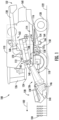
- FIG. 1 illustrates a partial sectional side view of an agricultural harvester 100, particularly illustrating various components of the harvester 100.
- the harvester 100 may be configured to move across a field in a direction of travel (e.g., as indicated by arrow 102) to harvest a standing or windrowed crop 104. While traversing the field, the harvester 100 may be configured to process the harvested grain or crop material (shown schematically in FIG. 2 as box 106) and store cleaned crop material 108 ( FIG. 2 ) within a grain or crop storage tank 110 of the harvester 100.
- the harvester 100 may be configured as an axial-flow type combine, wherein the harvested crop material 106 is threshed and separated while the crop material 106 is advanced by and along a longitudinally arranged rotor 112.
- the harvester 100 may have any suitable harvester configuration.
- the harvester 100 may be configured to clean the harvested crop material 106 via one or more components of a crop processing system 114 of the harvester 100.
- the harvester 100 may include a chassis or main frame 116 configured to support and/or couple to various components of the harvester 100.
- the harvester 100 may include a pair of driven, ground-engaging front wheels 118 and a pair of steerable rear wheels 120 that are coupled to the frame 116.
- the wheels 118, 120 may be configured to support the harvester 100 relative to a ground surface 122 and move the harvester 100 in the forward direction of travel 102 relative to the ground surface 122.
- the harvester 100 may include an operator's platform 124 having an operator's cab 126, and the crop processing system 114, all of which may be supported by the frame 116.
- the crop processing system 114 may be configured to perform various processing operations on the harvested crop material 106 as the crop processing system 114 operates to clean the crop material 106 between a harvesting implement (e.g., header 128) of the harvester 100 and the crop storage tank 110.
- An unloading system 130 may be configured to convey the cleaned crop material 108 from the crop storage tank 110 to an associated discharge location 132 on the harvester 100.
- the harvester 100 may include an engine and a transmission mounted on the frame 116. The transmission may be operably coupled to the engine and may provide variably adjusted gear ratios for transferring engine power to the wheels 118, 120 via a drive axle assembly (or via axles if multiple drive axles are employed).
- the header 128 and an associated feeder 136 of the crop processing system 114 may extend forward of the frame 116 and may be pivotally secured thereto for generally vertical movement.
- the feeder 136 may be configured to serve as support structure for the header 128.
- the feeder 136 may extend between a front end 138 coupled to the header 128 and a rear end 140 positioned adjacent to a threshing and separating assembly 142 of the crop processing system 114.
- the rear end 140 of the feeder 136 may be pivotally coupled to a portion of the harvester 100 to allow the front end 138 of the feeder 136 and, thus the header 128, to be moved upward and downward relative to the ground 122 to set the desired harvesting or cutting height for the header 128.
- the crop material 106 is severed from the standing crop by a sickle bar 144 at the front of the header 128 and delivered by a header auger 146 to the front end 138 of the feeder 136, which supplies the harvested crop material 106 to the threshing and separating assembly 142.
- the threshing and separating assembly 142 may include a cylindrical chamber 148 in which the rotor 112 is rotated to thresh and separate the harvested crop material 106 received therein. That is, the harvested crop material 106 is rubbed and beaten between the rotor 112 and the inner surfaces of the chamber 148, whereby the grain, seed, or the like, is loosened and separated from the straw.
- the harvested crop material 106 that has been separated by the threshing and separating assembly 142 may fall onto a crop cleaning assembly 150 of the crop processing system 114.
- the crop cleaning assembly 150 may include a series of pans 152 and associated sieves 154.
- the separated crop material 106 may be spread out via oscillation of the pans 152 and/or sieves 154 and may eventually fall through apertures or openings (not shown) defined in the sieves 154.
- a cleaning fan 158 may be positioned adjacent to one or more of the sieves 154 to provide an air flow through the sieves 154 that removes chaff and other impurities, or more generally material other than grain (MOG), from the crop material 106.
- the fan 158 may blow the impurities off of the crop material 106 for discharge from the harvester 100 through the outlet of a straw hood 160 positioned at the back end of the harvester 100.
- the fan 158 may also assist movement of the crop material 106 along the sieves 154.
- the cleaned crop material 108 passing through the sieves 154 may then be directed towards a crop delivery apparatus 162, such as a combination of an auger 166 positioned within a trough 164 and an elevator assembly 168, which may be configured to transfer the cleaned harvested crop 108 to the crop storage tank 110.
- the cleaned crop material 108 contained within the crop storage tank 110 may then be delivered to the unloading system 130 via one or more cross-augers 170 positioned at the bottom of the tank 110.
- the crop cleaning assembly 150 may include one or more components for cleaning the harvested crop material 106 and for delivering such material 106 to an associated crop delivery apparatus 162 for subsequent transport to the storage tank 110 of the harvester 100.
- the crop cleaning assembly 150 may include one or more vibrating or reciprocating sieves, such as an upper sieve 172 and a lower sieve 174, configured to receive harvested crop material 106 from the threshing and separating assembly 142 ( FIG. 1 ).
- the threshing and separating assembly 142 may separate the harvested grain or crop material 106 from MOG, such as straw, using the rotor 112 rotating within the cylindrical chamber 148.
- the threshing and separating assembly 142 may then deposit the harvested grain or crop material 106 onto the sieves 172, 174 for further cleaning.
- the crop material 106 may be initially deposited onto the upper sieve 172 of the crop cleaning assembly 150.
- the upper sieve 172 may be reciprocated such that the crop material 106 is translated across the upper sieve 172 as a flow 176 of harvested crop material 106, and is thereby cleaned, such that cleaned crop material 108 falls downwardly through openings in the upper sieve 172 towards the lower sieve 174.
- the lower sieve 174 may, in turn, be reciprocated such that the cleaned crop material 108 is further cleaned as it moves across the lower sieve 174 and that the cleaned crop material 108 falls through openings 156 in the lower sieve 174 towards a clean crop material sheet 178 disposed below the lower sieve 174. Any remaining uncleaned harvested crop material 106 or MOG not directed through the upper sieve 172 and the lower sieve 174 is directed as a flow 180 of MOG and remaining crop material 106 towards and/or along an auxiliary pan 182 to be re-threshed or to be exhausted from the harvester 100. As shown in FIG.
- the clean crop material sheet 178 is generally angled downwardly towards the crop delivery apparatus 162 such that the cleaned crop material 108 received from the lower sieve 174 is directed downwardly across the clean crop material sheet 178 towards the crop delivery apparatus 162 as a flow 184 of cleaned crop material 108.
- the crop delivery apparatus 162 may generally include the auger 166 ( FIG. 1 ) disposed within trough 164 that transfers the cleaned crop material 108 to a clean crop material conveyor 186, which then transports the cleaned crop material 108 to the storage tank 110.
- the clean crop material conveyor 186 may be an elevator assembly 168, such as the centrifugal discharge elevator shown in FIG. 2 .
- the elevator assembly 168 may generally include an elevator housing 188 defining an inlet end 190 at or adjacent to the downstream end of the clean crop material sheet 178 and an outlet end 192 at or adjacent to the storage tank 110.
- the elevator assembly 168 may also include a looped chain 194 and a plurality of crop material paddles or carriers 196 (hereinafter referred to as "carriers" 196) coupled to and evenly spaced apart on the looped chain 194.
- the chain 194 may generally be configured to move the carriers 196 within the elevator housing 188 along a looped travel path between the inlet and outlet ends 190, 192 of the elevator housing 188 around an upper shaft 198 (and an associated upper sprocket) positioned at an upper end of the looped travel path of the carriers 196 and a lower shaft 200 (and an associated lower sprocket) positioned at a lower end of the looped travel path of the carriers 196.
- An elevator motor may be coupled to one of the shafts 198, 200 (e.g., the upper shaft 198) such that the shaft is rotated about a rotational axis R and the associated sprocket drives the chain 220, thereby allowing the chain 194 and carriers 196 to travel in an endless loop within the elevator housing 188.
- the carriers 196 may fling or propel the cleaned crop material 108 into the storage tank 110 as the carriers 196 are looped around the upper shaft/sprocket about the rotational axis R.
- Cross-augers 170 positioned at the bottom of the storage tank 110 help agitate the cleaned crop material 108 for discharge from the harvester 100. It should be appreciated that the crop delivery apparatus 162 and carriers 196 may be configured in any way suitable for lifting the cleaned crop material 108 within the housing 188 of the elevator assembly 168.
- one or more of the sieves of the crop cleaning assembly may be coupled to a corresponding clean crop material sheet to form a unitary, sieve assembly configured for use within the harvester's crop processing system.
- the lower sieve 174 may be coupled to the adjacent clean crop material sheet 178 via one or more support elements to form a sieve assembly.
- Such a configuration may allow for the sieve and clean crop material sheet to be installed into and removed from the harvester 100 as an integral assembly, thereby facilitating more efficient installation and/or servicing of such components.
- the disclosed sieve assembly 210 may allow for an overall reduction in the space requirements for the crop cleaning assembly 150, as well as reduce the required number of assembly components (thereby reducing the overall weight of the crop cleaning assembly 150).
- FIGS. 3-5 various views of one embodiment of a sieve assembly 210 configured for use within a harvester 100 are illustrated in accordance with aspects of the present subject matter.
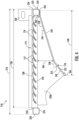
- FIG. 3 illustrates a perspective view of the sieve assembly 210.
- FIG. 4 illustrates a side-sectional view of various components of the sieve assembly 210 shown in FIG. 3 taken about line 4-4.
- FIG. 5 illustrates a perspective view of one of the support elements of the sieve assembly 210 shown in FIGS. 3 and 4 .
- the sieve assembly 210 may generally extend in a lateral direction along a width 212 defined between a first lateral side 214 of the sieve assembly and a second lateral side 216 of the sieve assembly 210. Additionally, as shown in FIGS. 3 and 4 , the sieve assembly 210 may generally define a length 218 in a lengthwise direction of the assembly 210 extending between a first assembly end 220 and a second assembly end 222. In accordance with aspects of the present subject matter, the sieve assembly 210 includes a sieve (e.g., sieve 174 of FIG.
- the sieve assembly 210 also includes one or more support elements 224, 228, 230 configured to be coupled directly between the sieve 174 and the clean crop material sheet 178, thereby providing a rigid structural connection between the assembly components.
- the disclosed sieve assembly 210 will generally be described herein as including the lower sieve 174 and the associated clean crop material sheet 178 of the crop cleaning assembly 150 described above with reference to FIG. 2 .
- the sieve assembly 210 may generally include any suitable sieve have any suitable sieve configuration and/or any suitable clean crop material sheet having any suitable sheet configuration.
- the sieve 174 of the sieve assembly 210 includes a first sieve end 232 and a second sieve end 234 and defines a length 236 in the lengthwise direction of the sieve assembly 210 between its first and second sieve ends 232, 234. Additionally, as shown in FIG. 3 , the sieve 174 may be configured to extend in the lateral direction across all or substantially all of the lateral width 212 of the sieve assembly 210 defined between its first and second lateral sides 214, 216.
- the first sieve end 232 corresponds to the upstream end of the sieve 174 and may be configured to be positioned generally proximate to the first assembly end 220 of the sieve assembly 210.
- the second sieve end 234 corresponds to the downstream end of the sieve 174 and may be configured to be positioned generally proximate to the second assembly end 222 of the sieve assembly 210.
- harvested crop material 106 may be configured to be deposited onto the sieve 174 (e.g., from the upper sieve 172).
- the harvested crop material 106 may then be translated along the length 236 of the sieve 174 from the first or upstream end 232 of the sieve 174 towards the second or downstream end 234 of the sieve 174 as the crop material 106 is being cleaned.
- the sieve 174 includes a plurality of openings 156 extending therethrough from an upper side 238 of the sieve 174 to a lower side 240 of the sieve 174.
- the sieve 174 may include a plurality of vanes 157 spaced apart from one another along the length 236 of the sieve 174 such that the openings 156 are defined between the vanes 157.
- the vanes 157 may be disposed along the length 236 of the sieve 174 such that only the cleaned crop material 108 or particles of a smaller size may fall through the openings 156.
- the position of the vanes 157 may be adjustable such that the size of the openings 156 may, in turn, be adjusted to accommodate harvested crop material 106 of different sizes and/or types.
- the vanes 157 may also help direct the flow of cleaned crop material 108 as such material 108 moves through the openings 156 towards the clean crop material sheet 178.
- the clean crop material sheet 178 of the sieve assembly 210 is configured to be positioned vertically below the sieve 174 so as to receive the flow of cleaned crop material 208 directed through the openings 156 defined in the sieve 174 along an upper side 242 of the sheet 178.
- the clean crop material sheet 178 extends lengthwise between a first sheet end 244 and a second sheet end 246 (e.g., along length 248 of the clean crop material sheet 178).
- a first sheet end 244 and a second sheet end 246 e.g., along length 248 of the clean crop material sheet 178.
- the clean crop material sheet 178 may be configured to extend in the lateral direction along all or substantially all of the lateral width 212 of the sieve assembly 210 (e.g., from the first lateral side 214 of the assembly 210 to the second lateral side 216 of the assembly 210).
- the first sheet end 244 of the clean crop material sheet 178 corresponds to the upstream end of the sheet 178 and may be configured to be positioned generally proximal to both the second or downstream end 234 of the sieve 174 and the second assembly end 222 of the sieve assembly 210.
- the second sheet end 246 corresponds to the downstream end of the clean crop material sheet 178 and may be configured to be positioned at or adjacent to an intake end of the crop delivery apparatus 162.
- the vanes 157 of the sieve 174 may be oriented such that the flow of cleaned crop material 108 transmitted through the openings 156 is generally directed towards the downstream end 246 of the clean crop material sheet 178.
- the clean crop material sheet 178 may be angled downwardly from its first, upstream end 244 towards its second, downstream end 246 such that the flow of cleaned crop material 208 is directed downwardly towards the adjacent crop delivery apparatus 162.
- the clean crop material sheet 178 may, in one embodiment, include a first angled section 250 and a second angled section 252.
- the first angled section 250 may generally extend lengthwise from a location proximate the first upstream end 244 of the sheet 178 to the intersection defined between the first and second angled sections 250, 252, while the second angled section 252 may generally extend lengthwise between the first angled section 250 and the second, downstream end 246 of the sheet 178.
- the first angled section 250 may be oriented at a first angle 254 relative to a reference plane 258 and the second angled section 252 may be oriented at a second angle 256 relative to the reference plane 258.
- the reference plane 258 generally corresponds to a horizontal reference plane such that the first and second angles 254, 256 extend downwardly from the reference plane 258.
- the first and second angles 254, 256 may differ such that the first angle 254 is smaller than the second angle 256.
- the second angled section 252 may be sloped more steeply relative to the reference plane 258 than the first angled section 250.
- a velocity of the flow of cleaned crop material 108 along the second angled section 250 may be greater than the velocity of the flow of the cleaned crop material 108 along the first angled section 250 of the clean crop material sheet 178.
- the clean crop material sheet 178 may include further angled sections, wherein each further section extends at a steeper angle relative to the reference plane 258 than the section upstream of and adjacent to such further section.
- the second angle 256 may be smaller than the first angle 254 such that the first angled section 254 may be sloped more steeply relative to the reference plane 258 than the second angled section 256 and such that, when the clean crop material sheet 178 includes further angled sections, each further section may extend either at a steeper angle or shallower angle relative to the reference plane 258 than the section upstream of and adjacent to such further section.
- the clean crop material sheet 178 may include one or more curved or actuate sections as opposed to (or in addition to) the angled sections described above.
- the sieve assembly 210 includes one or more support elements 224, 228, 230 directly coupled between the sieve 174 and the clean crop material sheet 178.
- the support element(s) 224, 228, 230 may be configured to provide structural support for the sieve 174 and the clean crop material sheet 178 within the harvester 100 and may also be configured to structurally couple the components together to form a unitary assembly.
- the support element(s) 224, 228, 230 may be configured to provide lateral and/or vertical stiffness or rigidity to the sieve 174 and/or the clean crop material sheet 178, thereby allowing such components to resist loads applied on the sieve assembly 204 to prevent, for example, undesired bending.
- the assembled components can be quickly and easily installed within and/or removed from the harvester 100 as an integral assembly 210.
- the disclosed support element(s) may include one or more lateral support elements 224, one or more vertical support elements 228, 230, and/or any combination thereof.
- the sieve assembly 210 includes a lateral support element 224 extending in the lateral direction (e.g., transverse to the flow of crop material 106 across the sieve 174 and the flow of cleaned crop material across the crop material sheet 178) along all or a portion of the lateral width 212 of the sieve assembly 210 that is configured to be coupled directly between the sieve 174 and the clean crop material sheet 178.
- the lateral support element 224 is configured to be fixedly coupled to the sieve 174 (e.g., via welding or mechanical fasteners) at or adjacent to its second or downstream end 234 and to the clean crop material sheet 178 (e.g., via welding or mechanical fasteners) at or adjacent to its first or upstream end 244.
- the lateral support element 224 is coupled between the adjacent ends 234, 244 of the sieve 174 and the clean crop material sheet 178 such that the lower side 240 of the sieve 174 contacts the top side of the lateral support element 224 while the upper side 242 of the clean crop material sheet 178 contacts the bottom side of the lateral support element 224.
- the lateral support element 224 may provide lateral stiffness and/or rigidity to both the sieve 174 and the clean crop material sheet 178 across the lateral width 212 of the sieve assembly 210.
- the second, downstream end 234 of the sieve 174 may be vertically spaced apart from the first, upstream end 244 of the clean crop material sheet 178 by a vertical distance or gap 260 that extends laterally (e.g., into the page in the view of FIG. 4 ) across the entire lateral width 212 of the sieve assembly 210.
- the lateral support element 224 may be coupled between the sieve 174 and the clean crop material sheet 178 so that the lateral support element 224 extends fully across the gap 260 (e.g., both vertically and laterally).
- the lateral support element 224 may enclose or otherwise fill-in the gap 260 defined between the sieve 174 and the clean crop material sheet 178, thereby preventing any cleaned crop material 108 from flowing through the gap 260.
- the lateral support element 224 may generally have any suitable configuration and/or may be formed from any suitable material that allows it to provide structural support for the sieve 174 and the clean crop material sheet 178.
- the lateral support element 224 is configured as a structural tube having a hollow, square-shaped cross-section and being formed from a substantially rigid material (e.g., steel).
- the lateral support element 224 may have any other suitable configuration, including any other suitable cross-sectional shape, that allows it to function as described herein.
- the sieve assembly may also include one or more vertical support elements 228, 230 coupled to both the sieve 174 and the clean crop material sheet 178 (e.g., via welding or mechanical fasteners) and extending vertically therebetween so as to provide vertical structural support for the sieve assembly 210.
- the vertical support element(s) 228, 230 may extend lengthwise between the sieve 174 and the clean crop material sheet 178 along all or a substantial portion of both the length 236 of the sieve 174 and the length 248 of the clean crop material sheet 178.
- the vertical support element(s) 228, 230 may be oriented in the lengthwise direction generally parallel to the flow of the cleaned crop material 108 along the clean crop material sheet 178.
- each vertical support element 228, 230 may, in one embodiment, include an upper feature 262 and a lower feature 264 for coupling the vertical support element(s) 228, 230 to the sieve 174 and the clean crop material sheet 178, respectively.
- the upper and lower features 262, 264 correspond to flanges configured to allow the vertical support element(s) 228, 230 to be coupled to the sieve 174 and the clean crop material sheet 178 via welding or suitable mechanical fasteners.
- the upper and lower features 262, 264 may correspond to any other suitable attachment features that allow the vertical support element(s) 228, 230 to be coupled between the sieve 174 and the clean crop material sheet 178, such as grooves, openings, mating features (e.g., male and/or female features), and/or the like.
- the vertical support element(s) of the sieve assembly 210 may include one or more vertically oriented side support elements 228, such as a first side support element 228A and a second side support element 228B.
- first side support element 228A may be configured to extend substantially vertically between the sieve 174 and the clean crop material sheet 178 along the first lateral side 214 of the sieve assembly 210 while the second side support element 228B may be configured to extend substantially vertically between the sieve 174 and the clean crop material sheet 178 along the second lateral side 216 of the sieve assembly 210.
- the first and second side support elements 228A, 228B may generally define sidewalls for the sieve assembly 210 that at least partially enclose or define an interior space 266 extending vertically between the sieve 174 and the clean crop material sheet 178 and laterally between the first and second lateral sides 214, 216 of the sieve assembly 210.
- the first and second side support elements 228A, 228B may also define outer lateral flow boundaries for the flow of cleaned crop material 108 passing through the lateral interior space 266 as it flows towards the downstream end 246 of the clean crop material sheet 178.
- the vertical support element(s) of the sieve assembly 210 may include one or more vertically oriented interior support elements 230.
- the sieve assembly 210 includes a pair of interior support element(s) 230 extending vertically between the sieve 174 and the clean crop material sheet 178 in the lengthwise direction along a substantial portion of the length 218 of the sieve assembly 210.
- the interior support elements 230 may be spaced apart laterally from each other and also from the lateral sides 214, 216 of the sieve assembly 210 (and/or the side support elements 228A, 228B) along the lateral width 212 of the assembly 210.
- the interior support element(s) 230 may also divide the lateral interior space 266 defined between the opposed lateral sides 214, 216 of the assembly 210 into separate flow channels, thereby dividing the flow of cleaned crop material 108 along the lateral width 212 of the sieve assembly 210 in order to further promote movement of the cleaned crop material 108 towards the downstream end 246 of the clean crop material sheet 178.
- the disclosed sieve assembly 210 may also include one or more additional features for mounting and/or otherwise supporting the assembly 210 within the harvester 100.
- the sieve assembly 210 may include a pair of mounting brackets 268 positioned at the second end 222 of the assembly 210, such as by mounting the brackets 268 to the opposed lateral ends of the lateral support element 224 and/or the opposed lateral sides of the sieve 174 and/or the clean crop material sheet 178.
- the mounting brackets 268 may be used to facilitate mounting the sieve assembly 210 within the harvester 100.
- the mounting brackets 268 may be configured to be coupled to suitable mounting features provided within the interior of the harvester 100 at the appropriate mounting location(s) for the assembly 210.
- the sieve assembly 210 may also include a front mounting bar 270 extending along the lateral width 212 of the sieve assembly 210 at its front or first assembly end 220.
- the front mounting bar 270 may be configured to engage corresponding internal mounting features of the harvester 100 to support the front end 220 of the assembly 210 within the harvester 100 upon installation of the assembly 210 therein.
Description
- The present subject matter relates generally to agricultural harvesters and, more particularly, to a sieve assembly configured for use within a crop processing system of an agricultural harvester.
- A harvester is an agricultural machine used to harvest and process crops. For instance, a combine harvester may be used to harvest grain crops, such as wheat, oats, rye, barley, corn, soybeans, and flax or linseed. In general, the objective is to complete several processes within one pass of the machine over a field. In this regard, most harvesters are equipped with a detachable harvesting implement, such as a header, which cuts and collects the crop from the field. The harvester also includes a crop processing system, which performs various processing operations (e.g., threshing, separating, cleaning, etc.) of the harvested crop received from the harvesting implement. Furthermore, the harvester includes a crop tank, which receives and stores the crop after processing.
- The crop processing system typically includes sieves or shoes that are reciprocally moved, usually in the fore and aft directions, to separate or sift the grain from tailings and material other than grain (MOG). With many harvesters, as the grain is cleaned from the MOG, it falls through the sieves and drops onto or into one or more separate clean grain pans that are disposed below the sieves.
- It is known to separately mount the sieves and the clean grain pans within the crop processing system of the harvester. Typically, separately mounting the sieves and the clean grain pans within the crop processing system requires that each of such components includes one or more separate support structures to provide structural rigidity to the component. With chassis configurations limiting the space available for the various components of the crop processing system, it is important that these components be as space-efficient as possible to increase the crop processing capacity of the harvester.
EP3075227A1 discloses a combine harvester whereby a fixed framework supports the clean grain sheets and the tailings sheet, using vibrators to cause movement of grain thereon. - Accordingly, an improved sieve assembly for a crop processing system that allows for more efficient and/or effective use of the space within an agricultural harvester would be welcomed in the technology.
- Aspects and advantages of the invention will be set forth in part in the following description, or may be obvious from the description, or may be learned through practice of the invention.
- In one embodiment, the present subject matter is directed to a sieve assembly for use in a crop processing system of an agricultural harvester according to claim 1.
- In another embodiment, the present subject matter is directed to a crop processing system of an agricultural harvester according to claim 9.
- These and other features, aspects and advantages of the present invention will become better understood with reference to the following description and appended claims.
- The accompanying drawings, which are incorporated in and constitute a part of this specification, illustrate embodiments of the invention and, together with the description, serve to explain the principles of the invention.
- A full and enabling disclosure of the present invention, including the best mode thereof, directed to one of ordinary skill in the art, is set forth in the specification, which makes reference to the appended figures, in which:
-
FIG. 1 illustrates a side view of one embodiment of an agricultural harvester in accordance with aspects of the present subject matter; -
FIG. 2 illustrates a side schematic view of one embodiment of a portion of a crop processing system suitable for use within the agricultural harvester shown inFIG. 1 in accordance with aspects of the present subject matter, particularly illustrating components of a crop cleaning assembly for cleaning the crop material harvested by the harvester and a crop delivery apparatus for delivering the cleaned crop material to an associated storage tank of the harvester; -
FIG. 3 illustrates a perspective view of one embodiment of a sieve assembly suitable for use within the agricultural harvester shown inFIG. 1 in accordance with aspects of the present subject matter, particularly illustrating the assembly including both a sieve for cleaning a flow of crop material and a clean crop material sheet for directing the cleaned crop towards an associated crop delivery apparatus of the harvester; -
FIG. 4 illustrates a side, cross-sectional view of a portion of the embodiment of the sieve assembly shown inFIG. 3 taken about line 4-4 in accordance with aspects of the present subject matter, particularly illustrating aspects of the sieve, the clean crop material sheet and one or more support elements coupled between the sieve and the clean crop material sheet; and -
FIG. 5 illustrates a perspective view of one embodiment of one of the support elements of the sieve assembly shown inFIG. 3 in accordance with aspects of the present subject matter. - Reference now will be made in detail to embodiments of the invention, one or more examples of which are illustrated in the drawings. Each example is provided by way of explanation of the invention, not limitation of the invention.
- The present subject matter is directed to a sieve assembly configured for use within a crop processing system of an agricultural harvester. Specifically, the sieve assembly includes a sieve for separating grain from tailings and material other than grain (MOG) within a flow of harvested crop material directed through the harvester and a clean crop material sheet for receiving the cleaned grain from the sieve and for directing the cleaned grain towards a crop delivery apparatus (e.g., a clean grain conveyor) for subsequent delivery to an associated crop storage tank of the harvester. In accordance with aspects of the present subject matter, the sieve and the clean crop material sheet are coupled together to form a unitary assembly within the harvester. One or more support elements are coupled directly between the sieve and the clean crop material sheet, thereby providing a rigid structural connection between the assembly components. Such a configuration may reduce the number of support elements required for supporting the sieve and the clean crop material sheet within the harvester, thereby increasing the available space within the harvester and reducing the overall weight of the crop processing system.
- As will be described below, the support element(s) include one or more lateral support elements coupled directly between the sieve and the clean crop material sheet, with the lateral support element(s) extending across a lateral width of the sieve assembly to provide lateral structural support to the assembly. The lateral support element(s) may enclose a gap formed between the downstream end of the sieve and the upstream end of the clean crop material sheet such that the flow of cleaned crop material cannot flow past the adjacent end of the assembly, thereby minimizing loss of cleaned crop material. Moreover, in addition to such lateral support element(s) (or as an alternative thereto), the support element(s) may include one or more vertical support elements coupled directly between the sieve and the clean crop material sheet, with the vertical support element(s) extending vertically between the sieve and the clean crop material sheet at one or more locations along the lateral width of the assembly to provide vertical structural support to the sieve assembly. Such vertical support element(s) may prevent flapping or excessive deformation of the sieve when reciprocated. In one embodiment, the vertical support element(s) may also at least partially enclose an interior space of the assembly defined between its opposed lateral sides to facilitate retention of the cleaned crop material within the enclosed lateral space.
- It should be appreciated that, by coupling the sieve and the clean crop material sheet together using the disclosed support element(s), the amount of space required for such components within the harvester may generally be reduced, thereby providing more capacity for the crop processing system of the harvester. Moreover, the sieve assembly formed using the support element(s) may allow for both the sieve and the associated clean crop material sheet to be installed within and/or removed from the agricultural harvester as a single, unitary assembly, thereby facilitating increased efficiency during the performance of both installation and/or servicing operations/
- The sieve of the disclosed sieve assembly extends along a length defined between a first upstream sieve end and a second downstream sieve end and is configured to process or clean a flow of harvested crop material as it is directed between its upstream and downstream ends. For example, as the flow of crop material moves towards the downstream end of the sieve, e.g., by a reciprocating motion of the sieve or by gravity, the flow of crop material may be cleaned (e.g., by separating grain from MOG) such that a flow of cleaned crop material falls through openings in the sieve. In some embodiments, multiple sieves may be employed.
- Additionally, the clean crop material sheet of the disclosed sieve assembly is positioned relative to the sieve such that it receives the flow of cleaned crop material falling through the openings in the sieve. As will be described below, the clean crop material sheet generally extends along a length defined between a first upstream sheet end and a second downstream sheet end, with the clean crop material sheet being configured to direct the flow of cleaned crop material from its upstream end to its downstream end. The upstream end of the clean crop material sheet is coupled to the downstream end of the sieve via one or more of the support elements (e.g., a lateral support element). The flow of cleaned crop material may be directed along all or a substantial portion of the length of the cleaned crop material sheet defined between its upstream and downstream ends. Additionally, in some embodiments, the clean crop material sheet may be angled downwardly from its upstream end to its downstream end to encourage movement of the flow of cleaned crop material towards the downstream end.
- Moreover, in several embodiments, the clean crop material sheet may define a profile configured to facilitate enhanced flow of the cleaned crop material towards its downstream end. For example, in one embodiment, the clean crop material sheet may include a first angled section extending downwardly relative to a horizontal reference plane from its upstream end at a first angle and a second angled section extending from the first angled section at a second angle relative to the horizontal reference plane, with the second angle being larger than the first angle. In such embodiment, the flow of cleaned crop material may experience an increase in acceleration and a resultant increase in velocity at the second angled section in comparison to the first angled section. Alternatively, the clean crop material sheet may include one or more curved sections extending between its upstream and downstream ends. In additional embodiments, the clean crop material sheet may have additional angled or curved sections along its length, with each successive section of the additional sections extending downwardly from the horizontal reference plane at a greater angle than a previous section. In such embodiment, the flow of cleaned crop material may experience multiple increases in acceleration and resultant velocity from the upstream end of the clean crop material sheet to the downstream end of the sheet. Such increases may help prevent the sieve from becoming blocked and may improve the overall efficiency of the cleaning system.
- Referring now to the drawings,
FIG. 1 illustrates a partial sectional side view of anagricultural harvester 100, particularly illustrating various components of theharvester 100. In general, theharvester 100 may be configured to move across a field in a direction of travel (e.g., as indicated by arrow 102) to harvest a standing or windrowedcrop 104. While traversing the field, theharvester 100 may be configured to process the harvested grain or crop material (shown schematically inFIG. 2 as box 106) and store cleaned crop material 108 (FIG. 2 ) within a grain orcrop storage tank 110 of theharvester 100. In one embodiment, theharvester 100 may be configured as an axial-flow type combine, wherein the harvestedcrop material 106 is threshed and separated while thecrop material 106 is advanced by and along a longitudinally arrangedrotor 112. However, it should be appreciated that, in alternative embodiments, theharvester 100 may have any suitable harvester configuration. Further, in accordance with aspects of the present subject matter, theharvester 100 may be configured to clean the harvestedcrop material 106 via one or more components of acrop processing system 114 of theharvester 100. - As shown in
FIG. 1 , theharvester 100 may include a chassis ormain frame 116 configured to support and/or couple to various components of theharvester 100. For example, in several embodiments, theharvester 100 may include a pair of driven, ground-engagingfront wheels 118 and a pair of steerablerear wheels 120 that are coupled to theframe 116. As such, thewheels harvester 100 relative to aground surface 122 and move theharvester 100 in the forward direction oftravel 102 relative to theground surface 122. Furthermore, theharvester 100 may include an operator'splatform 124 having an operator'scab 126, and thecrop processing system 114, all of which may be supported by theframe 116. As will be described below, thecrop processing system 114 may be configured to perform various processing operations on the harvestedcrop material 106 as thecrop processing system 114 operates to clean thecrop material 106 between a harvesting implement (e.g., header 128) of theharvester 100 and thecrop storage tank 110. Anunloading system 130 may be configured to convey the cleanedcrop material 108 from thecrop storage tank 110 to an associateddischarge location 132 on theharvester 100. Additionally, as is generally understood, theharvester 100 may include an engine and a transmission mounted on theframe 116. The transmission may be operably coupled to the engine and may provide variably adjusted gear ratios for transferring engine power to thewheels - As shown in
FIG. 1 , theheader 128 and an associatedfeeder 136 of thecrop processing system 114 may extend forward of theframe 116 and may be pivotally secured thereto for generally vertical movement. In general, thefeeder 136 may be configured to serve as support structure for theheader 128. For example, thefeeder 136 may extend between afront end 138 coupled to theheader 128 and arear end 140 positioned adjacent to a threshing and separatingassembly 142 of thecrop processing system 114. As is generally understood, therear end 140 of thefeeder 136 may be pivotally coupled to a portion of theharvester 100 to allow thefront end 138 of thefeeder 136 and, thus theheader 128, to be moved upward and downward relative to theground 122 to set the desired harvesting or cutting height for theheader 128. - As the
harvester 100 is propelled forwardly over the field with the standingcrop 104, thecrop material 106 is severed from the standing crop by asickle bar 144 at the front of theheader 128 and delivered by aheader auger 146 to thefront end 138 of thefeeder 136, which supplies the harvestedcrop material 106 to the threshing and separatingassembly 142. As is generally understood, the threshing and separatingassembly 142 may include acylindrical chamber 148 in which therotor 112 is rotated to thresh and separate the harvestedcrop material 106 received therein. That is, the harvestedcrop material 106 is rubbed and beaten between therotor 112 and the inner surfaces of thechamber 148, whereby the grain, seed, or the like, is loosened and separated from the straw. - The harvested
crop material 106 that has been separated by the threshing and separatingassembly 142 may fall onto acrop cleaning assembly 150 of thecrop processing system 114. In general, thecrop cleaning assembly 150 may include a series ofpans 152 and associated sieves 154. As is generally understood, the separatedcrop material 106 may be spread out via oscillation of thepans 152 and/orsieves 154 and may eventually fall through apertures or openings (not shown) defined in thesieves 154. Additionally, a cleaningfan 158 may be positioned adjacent to one or more of thesieves 154 to provide an air flow through thesieves 154 that removes chaff and other impurities, or more generally material other than grain (MOG), from thecrop material 106. For instance, thefan 158 may blow the impurities off of thecrop material 106 for discharge from theharvester 100 through the outlet of astraw hood 160 positioned at the back end of theharvester 100. Thefan 158 may also assist movement of thecrop material 106 along thesieves 154. The cleanedcrop material 108 passing through thesieves 154 may then be directed towards acrop delivery apparatus 162, such as a combination of anauger 166 positioned within atrough 164 and anelevator assembly 168, which may be configured to transfer the cleaned harvestedcrop 108 to thecrop storage tank 110. The cleanedcrop material 108 contained within thecrop storage tank 110 may then be delivered to theunloading system 130 via one or more cross-augers 170 positioned at the bottom of thetank 110. - Referring now to
FIG. 2 , a side schematic view of one embodiment of a portion of thecrop cleaning assembly 150 described above with reference toFIG. 1 is illustrated in accordance with aspects of the present subject matter. In general, thecrop cleaning assembly 150 may include one or more components for cleaning the harvestedcrop material 106 and for deliveringsuch material 106 to an associatedcrop delivery apparatus 162 for subsequent transport to thestorage tank 110 of theharvester 100. For example, as shown inFIG. 2 , thecrop cleaning assembly 150 may include one or more vibrating or reciprocating sieves, such as anupper sieve 172 and alower sieve 174, configured to receive harvestedcrop material 106 from the threshing and separating assembly 142 (FIG. 1 ). For example, the threshing and separatingassembly 142 may separate the harvested grain orcrop material 106 from MOG, such as straw, using therotor 112 rotating within thecylindrical chamber 148. The threshing and separatingassembly 142 may then deposit the harvested grain orcrop material 106 onto thesieves crop material 106 may be initially deposited onto theupper sieve 172 of thecrop cleaning assembly 150. Theupper sieve 172 may be reciprocated such that thecrop material 106 is translated across theupper sieve 172 as aflow 176 of harvestedcrop material 106, and is thereby cleaned, such that cleanedcrop material 108 falls downwardly through openings in theupper sieve 172 towards thelower sieve 174. Thelower sieve 174 may, in turn, be reciprocated such that the cleanedcrop material 108 is further cleaned as it moves across thelower sieve 174 and that the cleanedcrop material 108 falls throughopenings 156 in thelower sieve 174 towards a cleancrop material sheet 178 disposed below thelower sieve 174. Any remaining uncleaned harvestedcrop material 106 or MOG not directed through theupper sieve 172 and thelower sieve 174 is directed as aflow 180 of MOG and remainingcrop material 106 towards and/or along anauxiliary pan 182 to be re-threshed or to be exhausted from theharvester 100. As shown inFIG. 2 , the cleancrop material sheet 178 is generally angled downwardly towards thecrop delivery apparatus 162 such that the cleanedcrop material 108 received from thelower sieve 174 is directed downwardly across the cleancrop material sheet 178 towards thecrop delivery apparatus 162 as aflow 184 of cleanedcrop material 108. - In some embodiments, the
crop delivery apparatus 162 may generally include the auger 166 (FIG. 1 ) disposed withintrough 164 that transfers the cleanedcrop material 108 to a cleancrop material conveyor 186, which then transports the cleanedcrop material 108 to thestorage tank 110. In one embodiment, the cleancrop material conveyor 186 may be anelevator assembly 168, such as the centrifugal discharge elevator shown inFIG. 2 . In such an embodiment, theelevator assembly 168 may generally include anelevator housing 188 defining aninlet end 190 at or adjacent to the downstream end of the cleancrop material sheet 178 and anoutlet end 192 at or adjacent to thestorage tank 110. Theelevator assembly 168 may also include a loopedchain 194 and a plurality of crop material paddles or carriers 196 (hereinafter referred to as "carriers" 196) coupled to and evenly spaced apart on the loopedchain 194. Thechain 194 may generally be configured to move thecarriers 196 within theelevator housing 188 along a looped travel path between the inlet and outlet ends 190, 192 of theelevator housing 188 around an upper shaft 198 (and an associated upper sprocket) positioned at an upper end of the looped travel path of thecarriers 196 and a lower shaft 200 (and an associated lower sprocket) positioned at a lower end of the looped travel path of thecarriers 196. An elevator motor (not shown) may be coupled to one of theshafts 198, 200 (e.g., the upper shaft 198) such that the shaft is rotated about a rotational axis R and the associated sprocket drives thechain 220, thereby allowing thechain 194 andcarriers 196 to travel in an endless loop within theelevator housing 188. Thecarriers 196 may fling or propel the cleanedcrop material 108 into thestorage tank 110 as thecarriers 196 are looped around the upper shaft/sprocket about the rotationalaxis R. Cross-augers 170 positioned at the bottom of thestorage tank 110 help agitate the cleanedcrop material 108 for discharge from theharvester 100. It should be appreciated that thecrop delivery apparatus 162 andcarriers 196 may be configured in any way suitable for lifting the cleanedcrop material 108 within thehousing 188 of theelevator assembly 168. - In accordance with aspects of the present subject matter, one or more of the sieves of the crop cleaning assembly may be coupled to a corresponding clean crop material sheet to form a unitary, sieve assembly configured for use within the harvester's crop processing system. For example, as will be described below, the
lower sieve 174 may be coupled to the adjacent cleancrop material sheet 178 via one or more support elements to form a sieve assembly. Such a configuration may allow for the sieve and clean crop material sheet to be installed into and removed from theharvester 100 as an integral assembly, thereby facilitating more efficient installation and/or servicing of such components. In addition, the disclosedsieve assembly 210 may allow for an overall reduction in the space requirements for thecrop cleaning assembly 150, as well as reduce the required number of assembly components (thereby reducing the overall weight of the crop cleaning assembly 150). - Referring now to
FIGS. 3-5 , various views of one embodiment of asieve assembly 210 configured for use within aharvester 100 are illustrated in accordance with aspects of the present subject matter. Specifically,FIG. 3 illustrates a perspective view of thesieve assembly 210.FIG. 4 illustrates a side-sectional view of various components of thesieve assembly 210 shown inFIG. 3 taken about line 4-4. Additionally,FIG. 5 illustrates a perspective view of one of the support elements of thesieve assembly 210 shown inFIGS. 3 and4 . - As shown in
FIG. 3 , thesieve assembly 210 may generally extend in a lateral direction along awidth 212 defined between a firstlateral side 214 of the sieve assembly and a secondlateral side 216 of thesieve assembly 210. Additionally, as shown inFIGS. 3 and4 , thesieve assembly 210 may generally define alength 218 in a lengthwise direction of theassembly 210 extending between afirst assembly end 220 and asecond assembly end 222. In accordance with aspects of the present subject matter, thesieve assembly 210 includes a sieve (e.g., sieve 174 ofFIG. 2 ) for separating grain from MOG within the flow of harvested crop material directed through theharvester 100 and a clean crop material sheet (e.g.,sheet 178 ofFIG. 2 ) for receiving the cleaned grain from thesieve 174 and for directing the cleaned grain towards thecrop delivery apparatus 162 of thecrop cleaning assembly 150. Additionally, thesieve assembly 210 also includes one ormore support elements sieve 174 and the cleancrop material sheet 178, thereby providing a rigid structural connection between the assembly components. - It should be appreciated that, for purposes of discussion, the disclosed
sieve assembly 210 will generally be described herein as including thelower sieve 174 and the associated cleancrop material sheet 178 of thecrop cleaning assembly 150 described above with reference toFIG. 2 . However, in other embodiments, thesieve assembly 210 may generally include any suitable sieve have any suitable sieve configuration and/or any suitable clean crop material sheet having any suitable sheet configuration. - As shown in
FIG. 4 , thesieve 174 of thesieve assembly 210 includes afirst sieve end 232 and asecond sieve end 234 and defines alength 236 in the lengthwise direction of thesieve assembly 210 between its first and second sieve ends 232, 234. Additionally, as shown inFIG. 3 , thesieve 174 may be configured to extend in the lateral direction across all or substantially all of thelateral width 212 of thesieve assembly 210 defined between its first and secondlateral sides first sieve end 232 corresponds to the upstream end of thesieve 174 and may be configured to be positioned generally proximate to thefirst assembly end 220 of thesieve assembly 210. Similarly, in one embodiment, thesecond sieve end 234 corresponds to the downstream end of thesieve 174 and may be configured to be positioned generally proximate to thesecond assembly end 222 of thesieve assembly 210. During operation of thesieve assembly 210, harvestedcrop material 106 may be configured to be deposited onto the sieve 174 (e.g., from the upper sieve 172). The harvestedcrop material 106 may then be translated along thelength 236 of thesieve 174 from the first orupstream end 232 of thesieve 174 towards the second ordownstream end 234 of thesieve 174 as thecrop material 106 is being cleaned. - The
sieve 174 includes a plurality ofopenings 156 extending therethrough from anupper side 238 of thesieve 174 to alower side 240 of thesieve 174. In addition, thesieve 174 may include a plurality ofvanes 157 spaced apart from one another along thelength 236 of thesieve 174 such that theopenings 156 are defined between thevanes 157. As is generally understood, thevanes 157 may be disposed along thelength 236 of thesieve 174 such that only the cleanedcrop material 108 or particles of a smaller size may fall through theopenings 156. In some embodiments, the position of thevanes 157 may be adjustable such that the size of theopenings 156 may, in turn, be adjusted to accommodate harvestedcrop material 106 of different sizes and/or types. Thevanes 157 may also help direct the flow of cleanedcrop material 108 assuch material 108 moves through theopenings 156 towards the cleancrop material sheet 178. - The clean
crop material sheet 178 of thesieve assembly 210 is configured to be positioned vertically below thesieve 174 so as to receive the flow of cleaned crop material 208 directed through theopenings 156 defined in thesieve 174 along anupper side 242 of thesheet 178. As particularly shown inFIG. 4 , the cleancrop material sheet 178 extends lengthwise between afirst sheet end 244 and a second sheet end 246 (e.g., alonglength 248 of the clean crop material sheet 178). In addition, as shown inFIG. 3 , the cleancrop material sheet 178 may be configured to extend in the lateral direction along all or substantially all of thelateral width 212 of the sieve assembly 210 (e.g., from the firstlateral side 214 of theassembly 210 to the secondlateral side 216 of the assembly 210). Thefirst sheet end 244 of the cleancrop material sheet 178 corresponds to the upstream end of thesheet 178 and may be configured to be positioned generally proximal to both the second ordownstream end 234 of thesieve 174 and thesecond assembly end 222 of thesieve assembly 210. Similarly, thesecond sheet end 246 corresponds to the downstream end of the cleancrop material sheet 178 and may be configured to be positioned at or adjacent to an intake end of thecrop delivery apparatus 162. In one embodiment, thevanes 157 of thesieve 174 may be oriented such that the flow of cleanedcrop material 108 transmitted through theopenings 156 is generally directed towards thedownstream end 246 of the cleancrop material sheet 178. - In some embodiments, the clean
crop material sheet 178 may be angled downwardly from its first,upstream end 244 towards its second,downstream end 246 such that the flow of cleaned crop material 208 is directed downwardly towards the adjacentcrop delivery apparatus 162. For example, as shown inFIGS. 3 and4 , the cleancrop material sheet 178 may, in one embodiment, include a firstangled section 250 and a secondangled section 252. The firstangled section 250 may generally extend lengthwise from a location proximate the firstupstream end 244 of thesheet 178 to the intersection defined between the first and secondangled sections angled section 252 may generally extend lengthwise between the firstangled section 250 and the second,downstream end 246 of thesheet 178. As shown inFIG. 4 , the firstangled section 250 may be oriented at afirst angle 254 relative to areference plane 258 and the secondangled section 252 may be oriented at asecond angle 256 relative to thereference plane 258. In one embodiment, thereference plane 258 generally corresponds to a horizontal reference plane such that the first andsecond angles reference plane 258. As shown inFIG. 4 , the first andsecond angles first angle 254 is smaller than thesecond angle 256. In such an embodiment, the secondangled section 252 may be sloped more steeply relative to thereference plane 258 than the firstangled section 250. As such, a velocity of the flow of cleanedcrop material 108 along the secondangled section 250 may be greater than the velocity of the flow of the cleanedcrop material 108 along the firstangled section 250 of the cleancrop material sheet 178. It should be appreciated that, in other embodiments, the cleancrop material sheet 178 may include further angled sections, wherein each further section extends at a steeper angle relative to thereference plane 258 than the section upstream of and adjacent to such further section. Alternatively, in other embodiments, thesecond angle 256 may be smaller than thefirst angle 254 such that the firstangled section 254 may be sloped more steeply relative to thereference plane 258 than the secondangled section 256 and such that, when the cleancrop material sheet 178 includes further angled sections, each further section may extend either at a steeper angle or shallower angle relative to thereference plane 258 than the section upstream of and adjacent to such further section. In yet another embodiment, the cleancrop material sheet 178 may include one or more curved or actuate sections as opposed to (or in addition to) the angled sections described above. - As indicated above, the
sieve assembly 210 includes one ormore support elements sieve 174 and the cleancrop material sheet 178. In general, the support element(s) 224, 228, 230 may be configured to provide structural support for thesieve 174 and the cleancrop material sheet 178 within theharvester 100 and may also be configured to structurally couple the components together to form a unitary assembly. For example, the support element(s) 224, 228, 230 may be configured to provide lateral and/or vertical stiffness or rigidity to thesieve 174 and/or the cleancrop material sheet 178, thereby allowing such components to resist loads applied on the sieve assembly 204 to prevent, for example, undesired bending. In addition, by structurally connecting thesieve 174 and the cleancrop material sheet 178 together via the support element(s) 224, 228, 230, the assembled components can be quickly and easily installed within and/or removed from theharvester 100 as anintegral assembly 210. As will be described below, in several embodiments, the disclosed support element(s) may include one or morelateral support elements 224, one or morevertical support elements 228, 230, and/or any combination thereof. - The
sieve assembly 210 includes alateral support element 224 extending in the lateral direction (e.g., transverse to the flow ofcrop material 106 across thesieve 174 and the flow of cleaned crop material across the crop material sheet 178) along all or a portion of thelateral width 212 of thesieve assembly 210 that is configured to be coupled directly between thesieve 174 and the cleancrop material sheet 178. As particularly shown inFIG. 4 , thelateral support element 224 is configured to be fixedly coupled to the sieve 174 (e.g., via welding or mechanical fasteners) at or adjacent to its second ordownstream end 234 and to the clean crop material sheet 178 (e.g., via welding or mechanical fasteners) at or adjacent to its first orupstream end 244. Thelateral support element 224 is coupled between the adjacent ends 234, 244 of thesieve 174 and the cleancrop material sheet 178 such that thelower side 240 of thesieve 174 contacts the top side of thelateral support element 224 while theupper side 242 of the cleancrop material sheet 178 contacts the bottom side of thelateral support element 224. As a result, thelateral support element 224 may provide lateral stiffness and/or rigidity to both thesieve 174 and the cleancrop material sheet 178 across thelateral width 212 of thesieve assembly 210. - As shown in
FIG. 4 , in one embodiment, the second,downstream end 234 of thesieve 174 may be vertically spaced apart from the first,upstream end 244 of the cleancrop material sheet 178 by a vertical distance orgap 260 that extends laterally (e.g., into the page in the view ofFIG. 4 ) across theentire lateral width 212 of thesieve assembly 210. In such an embodiment, thelateral support element 224 may be coupled between thesieve 174 and the cleancrop material sheet 178 so that thelateral support element 224 extends fully across the gap 260 (e.g., both vertically and laterally). As a result, thelateral support element 224 may enclose or otherwise fill-in thegap 260 defined between thesieve 174 and the cleancrop material sheet 178, thereby preventing any cleanedcrop material 108 from flowing through thegap 260. - It should be appreciated that the
lateral support element 224 may generally have any suitable configuration and/or may be formed from any suitable material that allows it to provide structural support for thesieve 174 and the cleancrop material sheet 178. For example, as shown in the illustrated embodiment, thelateral support element 224 is configured as a structural tube having a hollow, square-shaped cross-section and being formed from a substantially rigid material (e.g., steel). However, in other embodiments, thelateral support element 224 may have any other suitable configuration, including any other suitable cross-sectional shape, that allows it to function as described herein. - Additionally, as indicated above, the sieve assembly may also include one or more
vertical support elements 228, 230 coupled to both thesieve 174 and the clean crop material sheet 178 (e.g., via welding or mechanical fasteners) and extending vertically therebetween so as to provide vertical structural support for thesieve assembly 210. In several embodiments, the vertical support element(s) 228, 230 may extend lengthwise between thesieve 174 and the cleancrop material sheet 178 along all or a substantial portion of both thelength 236 of thesieve 174 and thelength 248 of the cleancrop material sheet 178. In addition, in one embodiment, the vertical support element(s) 228, 230 may be oriented in the lengthwise direction generally parallel to the flow of the cleanedcrop material 108 along the cleancrop material sheet 178. - As particularly shown in
FIG. 5 , each vertical support element 228, 230 (or a portion thereof) may, in one embodiment, include anupper feature 262 and alower feature 264 for coupling the vertical support element(s) 228, 230 to thesieve 174 and the cleancrop material sheet 178, respectively. For example, in the illustrated embodiment, the upper andlower features sieve 174 and the cleancrop material sheet 178 via welding or suitable mechanical fasteners. However, in other embodiments, the upper andlower features sieve 174 and the cleancrop material sheet 178, such as grooves, openings, mating features (e.g., male and/or female features), and/or the like. - In several embodiments, the vertical support element(s) of the
sieve assembly 210 may include one or more vertically oriented side support elements 228, such as a firstside support element 228A and a secondside support element 228B. As particularly shown inFIG. 3 , the firstside support element 228A may be configured to extend substantially vertically between thesieve 174 and the cleancrop material sheet 178 along the firstlateral side 214 of thesieve assembly 210 while the secondside support element 228B may be configured to extend substantially vertically between thesieve 174 and the cleancrop material sheet 178 along the secondlateral side 216 of thesieve assembly 210. In such an embodiment, the first and secondside support elements sieve assembly 210 that at least partially enclose or define aninterior space 266 extending vertically between thesieve 174 and the cleancrop material sheet 178 and laterally between the first and secondlateral sides sieve assembly 210. As such, in addition to providing vertical structural support for thesieve assembly 210, the first and secondside support elements crop material 108 passing through the lateralinterior space 266 as it flows towards thedownstream end 246 of the cleancrop material sheet 178. - Moreover, in addition to the
side support elements sieve assembly 210 may include one or more vertically orientedinterior support elements 230. For example, as shown inFIG. 3 , thesieve assembly 210 includes a pair of interior support element(s) 230 extending vertically between thesieve 174 and the cleancrop material sheet 178 in the lengthwise direction along a substantial portion of thelength 218 of thesieve assembly 210. In such an embodiment, theinterior support elements 230 may be spaced apart laterally from each other and also from thelateral sides side support elements lateral width 212 of theassembly 210. As such, in addition to providing vertical structural support between thesieve 174 and the cleancrop material sheet 178, the interior support element(s) 230 may also divide the lateralinterior space 266 defined between the opposedlateral sides assembly 210 into separate flow channels, thereby dividing the flow of cleanedcrop material 108 along thelateral width 212 of thesieve assembly 210 in order to further promote movement of the cleanedcrop material 108 towards thedownstream end 246 of the cleancrop material sheet 178. - It should be appreciated that the disclosed
sieve assembly 210 may also include one or more additional features for mounting and/or otherwise supporting theassembly 210 within theharvester 100. For example, as shown inFIGS. 3 and4 , in one embodiment, thesieve assembly 210 may include a pair of mountingbrackets 268 positioned at thesecond end 222 of theassembly 210, such as by mounting thebrackets 268 to the opposed lateral ends of thelateral support element 224 and/or the opposed lateral sides of thesieve 174 and/or the cleancrop material sheet 178. In such an embodiment, the mountingbrackets 268 may be used to facilitate mounting thesieve assembly 210 within theharvester 100. For example, the mountingbrackets 268 may be configured to be coupled to suitable mounting features provided within the interior of theharvester 100 at the appropriate mounting location(s) for theassembly 210. Similarly, as shown inFIGS. 3 and4 , thesieve assembly 210 may also include a front mountingbar 270 extending along thelateral width 212 of thesieve assembly 210 at its front orfirst assembly end 220. In one embodiment, thefront mounting bar 270 may be configured to engage corresponding internal mounting features of theharvester 100 to support thefront end 220 of theassembly 210 within theharvester 100 upon installation of theassembly 210 therein.
Claims (13)
- A sieve assembly (210) for use in a crop processing system (114) of an agricultural harvester (100), the sieve assembly (210) comprising a sieve (174) extending along a length (236) defined between a first sieve end (232) and a second sieve end (234), the sieve (174) configured to process a flow of crop material (106), the sieve (174) defining a plurality of openings (156) through which cleaned crop material (108) of the flow of crop material (106) is directed, the sieve assembly (210) further comprising a crop material sheet (178) extending along a length (248) defined between a first sheet end (244) and a second sheet end (246), the crop material sheet (178) configured to receive the cleaned crop material (108) directed through the plurality of openings (156) of the sieve (174), the crop material sheet (178) transporting the cleaned crop material (108) towards a separate component (186) of the crop processing system (114), the sieve assembly (210) comprising at least one support element (224; 228A; 228B; 230) directly coupled between the sieve (174) and the crop material sheet (178), the at least one support element structurally connecting the sieve (174) to the crop material sheet (178), wherein the at least one support element comprises a lateral support element (224) directly coupled between the sieve (174) and the crop material sheet (178), the lateral support element (224) extending substantially transverse to the flow of crop material (106) along the sieve (174), wherein the first sieve end (232) corresponds to an upstream end of the sieve (174) and the second sieve end (234) corresponds to a downstream end of the sieve (174) relative to the flow of crop material (106), and wherein the first sheet end (244) corresponds to an upstream end of the crop material sheet (178) and the second sheet end (246) corresponds to a downstream end of the crop material sheet (178) relative to a flow of the cleaned crop material (108) and characterised in that the lateral support element (224) is fixedly coupled between the second sieve end (234) and the first sheet end (244) such that a lower side (240) of the sieve (174) contacts a top side of the lateral support element (224) while an upper side (242) of the crop material sheet (178) contacts a bottom side of the lateral support element (224).
- The sieve assembly (210) as in claim 1, wherein the lateral width (212) is defined between a first lateral side (214) of the sieve assembly (210) and a second lateral side (216) of the sieve assembly (210), wherein a gap (260) is defined between the second sieve end (234) of the sieve (174) and the first sheet end (244) of the crop material sheet (178), the lateral support element (224) being positioned relative to the sieve (174) and the crop material sheet (178) such that the lateral support element (224) extends across the gap (260) along a lateral width (212) of the sieve assembly (210).
- The sieve assembly (210) as in claim 1, wherein the at least one support element comprises at least one vertical support element (228A; 228B; 230) coupled directly between the sieve (174) and the crop material sheet (178).
- The sieve assembly (210) as in claim 3, wherein the at least one vertical support comprises a plurality of vertical support elements (228A, 228B, 230) coupled between the sieve (174) and the crop material sheet (178), the plurality of vertical support elements (228A, 228B, 230) being spaced apart along a lateral width (212) of the sieve assembly (210).
- The sieve assembly (210) as in claim 4, wherein the lateral width (212) is defined between a first lateral side (214) of the sieve assembly (210) and a second lateral side (216) of the sieve assembly (210), the plurality of vertical support elements (228A, 228B, 230) comprising a first side support element (228A) extending vertically between the sieve (174) and the crop material sheet (178) along the first lateral side (214) of the sieve assembly (210) and a second side support element (228B) extending vertically between the sieve (174) and the crop material sheet (178) along the second lateral side (216) of the sieve assembly (210).
- The sieve assembly (210) as in claim 5, wherein the first and second side support elements (228A, 228B) are configured to at least partially enclose a lateral interior space (266) defined between the first and second lateral sides (214, 216) of the sieve assembly (210).
- The sieve assembly (210) as in claim 5, wherein the plurality of vertical support elements (228A, 228B, 230) further comprises at least one interior support element (230) extending vertically between the sieve (174) and the crop material sheet (178) at a location between the first and second side support elements (228A, 228B).
- The sieve assembly (210) as in any preceding claim, wherein the crop material sheet (178) includes a first angled section (250) and a second angled section (252), the first angled section (250) being oriented at a first angle (254) relative to a reference plane (258) and the second angled section (252) being oriented at a second angle (256) relative to the reference plane (258), the first angle (254) differing from the second angle (256).
- A crop processing system (114) of an agricultural harvester (100), the crop processing system (114) comprising a crop delivery apparatus (186), a storage tank (110) configured to receive a flow of cleaned crop material (108) from the crop delivery apparatus (186), and a sieve assembly (210) according to any of the preceding claims.
- The crop processing system (114) as in claim 9, wherein the at least one support element comprises a lateral support element (224) directly coupled between the sieve (174) and the crop material sheet (178), the lateral support element (224) extending substantially transverse to the flow of crop material (106).
- The crop processing system (114) as in claim 10, wherein the first sieve end (232) corresponds to an upstream end of the sieve (174) and the second sieve end (234) corresponds to a downstream end of the sieve (174) relative to the flow of crop material (106), and wherein the first sheet end (244) corresponds to an upstream end of the crop material sheet (178) and the second sheet end (246) corresponds to a downstream end of the crop material sheet (178) relative to the flow of cleaned crop material (108), the second sieve end (234) and the first sheet end (244) being fixedly coupled to the lateral support element (224).
- The crop processing system (114) as in claim 11, wherein a gap (260) is defined between the second sieve end (234) of the sieve (174) and the first sheet end (244) of the crop material sheet (178), the lateral support element (224) being positioned relative to the sieve (174) and the crop material sheet (178) such that the lateral support element (224) extends across the gap (260) along a lateral width (212) of the sieve assembly (210).
- The crop processing system (114) as in claim 9, wherein the at least one support element comprises at least one vertical support element (228A; 228B; 230) coupled directly between the sieve (174) and the crop material sheet (178).
Applications Claiming Priority (1)
| Application Number | Priority Date | Filing Date | Title |
|---|---|---|---|
| US15/969,230 US10827683B2 (en) | 2018-05-02 | 2018-05-02 | Sieve assembly for a crop processing system of an agricultural harvester |
Publications (3)
| Publication Number | Publication Date |
|---|---|
| EP3563661A2 EP3563661A2 (en) | 2019-11-06 |
| EP3563661A3 EP3563661A3 (en) | 2019-11-27 |
| EP3563661B1 true EP3563661B1 (en) | 2023-11-08 |
Family
ID=66334221
Family Applications (1)
| Application Number | Title | Priority Date | Filing Date |
|---|---|---|---|
| EP19171694.3A Active EP3563661B1 (en) | 2018-05-02 | 2019-04-29 | Sieve assembly for a crop processing system of an agricultural harvester |
Country Status (3)
| Country | Link |
|---|---|
| US (2) | US10827683B2 (en) |
| EP (1) | EP3563661B1 (en) |
| BR (1) | BR102019008818A2 (en) |
Families Citing this family (1)
| Publication number | Priority date | Publication date | Assignee | Title |
|---|---|---|---|---|
| US11877538B1 (en) | 2022-08-30 | 2024-01-23 | Calmer Holding Company, Llc | Threshing grains and legumes utilizing concaves with adjustable openings |
Family Cites Families (39)
| Publication number | Priority date | Publication date | Assignee | Title |
|---|---|---|---|---|
| US2675809A (en) * | 1954-04-20 | Combine having automatic leveling | ||
| US1027365A (en) * | 1910-09-02 | 1912-05-21 | Joseph D West | Sheet-metal fish-back for grain-separators. |
| US2190262A (en) * | 1939-03-17 | 1940-02-13 | Geist Adolf | Shaker pan |
| US2939581A (en) * | 1956-08-16 | 1960-06-07 | Massey Ferguson Inc | Combine cleaning shoe |
| US3757797A (en) * | 1969-04-22 | 1973-09-11 | B Mathews | Combine |
| US4208858A (en) * | 1979-02-12 | 1980-06-24 | Sperry Rand Corporation | Isolated pneumatic cleaning system |
| DE3042732A1 (en) * | 1979-11-14 | 1981-05-27 | Sperry N.V., Zedelgem | HARVESTER |
| DE3042735A1 (en) * | 1979-11-14 | 1981-05-27 | Sperry N.V., Zedelgem | HARVESTER |
| DE3042733C3 (en) * | 1979-11-14 | 1997-03-13 | Ford New Holland Inc | Harvester |
| US4332262A (en) * | 1979-11-14 | 1982-06-01 | Sperry Corporation | Combine harvester |
| US4480643A (en) | 1982-07-14 | 1984-11-06 | Murry W. Schuler | Sieve plate baffle attachment for grain combines |
| US4531528A (en) | 1983-03-07 | 1985-07-30 | Deere & Company | Cleaning shoe for a combine |
| US4535788A (en) * | 1984-10-11 | 1985-08-20 | Sperry Corporation | Lateral leveling mechanism for combine cleaning apparatus |
| US4561972A (en) | 1984-12-04 | 1985-12-31 | Murry W. Schuler | Combine sieve plate |
| EP0312655B1 (en) * | 1987-10-22 | 1993-12-22 | New Holland Belgium N.V. | Combine harvester cleaning apparatus |
| GB2293080A (en) * | 1994-09-17 | 1996-03-20 | New Holland Belguim Nv | Grain cleaner for combine harvester |
| US6672957B2 (en) * | 2002-03-28 | 2004-01-06 | Agco Corporation | Combine harvester cleaning apparatus |
| DE102005026608A1 (en) | 2005-06-09 | 2007-01-04 | Deere & Company, Moline | Cleaning device for a combine harvester |
| DE102005027741A1 (en) * | 2005-06-16 | 2007-01-18 | Deere & Company, Moline | Sieve for a cleaning device of a combine harvester |
| US7297051B1 (en) | 2006-04-26 | 2007-11-20 | Cnh America Llc | Clean grain and tailings conveying system for an agricultural combine |
| GB2450483A (en) * | 2007-06-25 | 2008-12-31 | Cnh Belgium Nv | A Grain cleaning system for a combine harvester |
| US8002616B2 (en) * | 2008-04-22 | 2011-08-23 | Cnh America Llc | Agricultural combine with internal cob de-husking apparatus and system |
| DE102009000797B4 (en) * | 2009-02-12 | 2017-05-11 | Deere & Company | Sieve arrangement for a combine harvester |
| US10111386B2 (en) * | 2012-01-03 | 2018-10-30 | Cnh Industrial America Llc | Harvester delivery control system |
| US20140128133A1 (en) * | 2012-11-02 | 2014-05-08 | Agco Corporation | Harvester having chaffer with tiltable section |
| US8821229B2 (en) * | 2012-12-06 | 2014-09-02 | Cnh Industrial America Llc | Grain cleaning system for an agricultural combine |
| US8939829B2 (en) * | 2012-12-14 | 2015-01-27 | Cnh Industrial America Llc | Combine linear side-shake cleaning control system |
| BE1021136B1 (en) * | 2013-03-12 | 2016-02-22 | Cnh Industrial Belgium Nv | CUTTER WITH ADJUSTABLE CLEANING SHOE SET-UP |
| US9258945B2 (en) * | 2013-09-20 | 2016-02-16 | Deere & Company | Hanger mount for a reciprocating sieve |
| US9198359B2 (en) | 2013-09-20 | 2015-12-01 | Deere & Company | Frame for a reciprocating sieve |
| US9226450B2 (en) * | 2013-09-20 | 2016-01-05 | Deere & Company | Lightweight hybrid material reciprocating sieve |
| BE1021892B1 (en) * | 2014-05-28 | 2016-01-25 | Cnh Industrial Belgium Nv | DRIVE UNIT FOR THE CLEANING SYSTEM OF A CUTTER |
| BE1022661B1 (en) | 2015-03-31 | 2016-06-29 | Cnh Industrial Belgium Nv | IMPROVEMENTS OF OR CONCERNING GRAIN CLEANERS FOR MOWING THREADERS |
| GB201515948D0 (en) * | 2015-09-09 | 2015-10-21 | Agco Int Gmbh | Grain cleaning system in a combine harvester |
| CN105875077A (en) | 2016-04-13 | 2016-08-24 | 济南大学 | Double-layer sieve plate type corn harvester cleaning device |
| US10568267B2 (en) * | 2017-12-16 | 2020-02-25 | Deere & Company | Harvester separation frame orientation adjustment |
| RU180324U1 (en) * | 2018-02-15 | 2018-06-08 | Федеральное государственное бюджетное образовательное учреждение высшего образования "Российский государственный аграрный университет - МСХА имени К.А. Тимирязева" (ФГБОУ ВО РГАУ - МСХА имени К.А. Тимирязева) | Combine Harvester Cleaning |
| DE102018121052A1 (en) * | 2018-08-29 | 2020-03-05 | Claas Selbstfahrende Erntemaschinen Gmbh | Component for a combine and combine with the component |
| DE102020109788A1 (en) * | 2020-04-08 | 2021-10-14 | Claas Selbstfahrende Erntemaschinen Gmbh | Harvester |
-
2018
- 2018-05-02 US US15/969,230 patent/US10827683B2/en active Active
-
2019
- 2019-04-29 EP EP19171694.3A patent/EP3563661B1/en active Active
- 2019-04-30 BR BR102019008818-4A patent/BR102019008818A2/en unknown
-
2020
- 2020-09-29 US US17/036,321 patent/US11771007B2/en active Active
Also Published As
| Publication number | Publication date |
|---|---|
| US10827683B2 (en) | 2020-11-10 |
| US11771007B2 (en) | 2023-10-03 |
| EP3563661A2 (en) | 2019-11-06 |
| US20210007285A1 (en) | 2021-01-14 |
| US20190335667A1 (en) | 2019-11-07 |
| BR102019008818A2 (en) | 2019-11-19 |
| EP3563661A3 (en) | 2019-11-27 |
Similar Documents
| Publication | Publication Date | Title |
|---|---|---|
| US6447394B1 (en) | Axial flow combine separator upper guide cover with fin pitch angle | |
| EP2663175B1 (en) | Combine harvester grain cleaning apparatus | |
| US7260967B2 (en) | Elevator slats for an agricultural harvesting machine | |
| US5624315A (en) | Cleaning means for an agricultural harvesting machine | |
| EP2721917B1 (en) | Slat for a material moving system for an agricultural harvesting machine | |
| WO2021089734A1 (en) | Agricultural harvester including a threshing drum with rasp bars having crop egress gaps | |
| US20060025186A1 (en) | Axial flow combine harvester with adaptable threshing unit | |
| US11771007B2 (en) | Sieve assembly for a crop processing system of an agricultural harvester | |
| EP3235365B1 (en) | Threshing and separating system for an agricultural harvester | |
| US7022013B1 (en) | Axial flow combine harvester with adaptable separating unit | |
| EP1529436B1 (en) | Axial flow combine harvester with adaptable separating unit |
Legal Events
| Date | Code | Title | Description |
|---|---|---|---|
| PUAI | Public reference made under article 153(3) epc to a published international application that has entered the european phase |
Free format text: ORIGINAL CODE: 0009012 |
|
| STAA | Information on the status of an ep patent application or granted ep patent |
Free format text: STATUS: THE APPLICATION HAS BEEN PUBLISHED |
|
| PUAL | Search report despatched |
Free format text: ORIGINAL CODE: 0009013 |
|
| AK | Designated contracting states |
Kind code of ref document: A2 Designated state(s): AL AT BE BG CH CY CZ DE DK EE ES FI FR GB GR HR HU IE IS IT LI LT LU LV MC MK MT NL NO PL PT RO RS SE SI SK SM TR |
|
| AX | Request for extension of the european patent |
Extension state: BA ME |
|
| AK | Designated contracting states |
Kind code of ref document: A3 Designated state(s): AL AT BE BG CH CY CZ DE DK EE ES FI FR GB GR HR HU IE IS IT LI LT LU LV MC MK MT NL NO PL PT RO RS SE SI SK SM TR |
|
| AX | Request for extension of the european patent |
Extension state: BA ME |
|
| RIC1 | Information provided on ipc code assigned before grant |
Ipc: A01F 12/44 20060101AFI20191024BHEP |
|
| STAA | Information on the status of an ep patent application or granted ep patent |
Free format text: STATUS: REQUEST FOR EXAMINATION WAS MADE |
|
| 17P | Request for examination filed |
Effective date: 20200527 |
|
| RBV | Designated contracting states (corrected) |
Designated state(s): AL AT BE BG CH CY CZ DE DK EE ES FI FR GB GR HR HU IE IS IT LI LT LU LV MC MK MT NL NO PL PT RO RS SE SI SK SM TR |
|
| STAA | Information on the status of an ep patent application or granted ep patent |
Free format text: STATUS: EXAMINATION IS IN PROGRESS |
|
| 17Q | First examination report despatched |
Effective date: 20220204 |
|
| GRAP | Despatch of communication of intention to grant a patent |
Free format text: ORIGINAL CODE: EPIDOSNIGR1 |
|
| STAA | Information on the status of an ep patent application or granted ep patent |
Free format text: STATUS: GRANT OF PATENT IS INTENDED |
|
| INTG | Intention to grant announced |
Effective date: 20230626 |
|
| GRAS | Grant fee paid |
Free format text: ORIGINAL CODE: EPIDOSNIGR3 |
|
| GRAA | (expected) grant |
Free format text: ORIGINAL CODE: 0009210 |
|
| STAA | Information on the status of an ep patent application or granted ep patent |
Free format text: STATUS: THE PATENT HAS BEEN GRANTED |
|
| AK | Designated contracting states |
Kind code of ref document: B1 Designated state(s): AL AT BE BG CH CY CZ DE DK EE ES FI FR GB GR HR HU IE IS IT LI LT LU LV MC MK MT NL NO PL PT RO RS SE SI SK SM TR |
|
| REG | Reference to a national code |
Ref country code: GB Ref legal event code: FG4D |
|
| REG | Reference to a national code |
Ref country code: CH Ref legal event code: EP |
|
| REG | Reference to a national code |
Ref country code: DE Ref legal event code: R096 Ref document number: 602019040920 Country of ref document: DE |
|
| REG | Reference to a national code |
Ref country code: IE Ref legal event code: FG4D |
|
| REG | Reference to a national code |
Ref country code: LT Ref legal event code: MG9D |
|
| REG | Reference to a national code |
Ref country code: NL Ref legal event code: MP Effective date: 20231108 |
|
| PG25 | Lapsed in a contracting state [announced via postgrant information from national office to epo] |
Ref country code: GR Free format text: LAPSE BECAUSE OF FAILURE TO SUBMIT A TRANSLATION OF THE DESCRIPTION OR TO PAY THE FEE WITHIN THE PRESCRIBED TIME-LIMIT Effective date: 20240209 |
|
| PG25 | Lapsed in a contracting state [announced via postgrant information from national office to epo] |
Ref country code: IS Free format text: LAPSE BECAUSE OF FAILURE TO SUBMIT A TRANSLATION OF THE DESCRIPTION OR TO PAY THE FEE WITHIN THE PRESCRIBED TIME-LIMIT Effective date: 20240308 |