EP3563650B1 - Cooling device, converter with a cooling device and method for cooling a converter - Google Patents
Cooling device, converter with a cooling device and method for cooling a converter Download PDFInfo
- Publication number
- EP3563650B1 EP3563650B1 EP17804819.5A EP17804819A EP3563650B1 EP 3563650 B1 EP3563650 B1 EP 3563650B1 EP 17804819 A EP17804819 A EP 17804819A EP 3563650 B1 EP3563650 B1 EP 3563650B1
- Authority
- EP
- European Patent Office
- Prior art keywords
- cooling
- evaporative
- fluid
- converter
- cooling apparatus
- Prior art date
- Legal status (The legal status is an assumption and is not a legal conclusion. Google has not performed a legal analysis and makes no representation as to the accuracy of the status listed.)
- Active
Links
- 238000001816 cooling Methods 0.000 title claims description 272
- 238000000034 method Methods 0.000 title claims description 8
- 239000012809 cooling fluid Substances 0.000 claims description 44
- 239000012530 fluid Substances 0.000 claims description 23
- 238000001704 evaporation Methods 0.000 claims description 11
- 230000008020 evaporation Effects 0.000 description 9
- 238000011161 development Methods 0.000 description 4
- 230000018109 developmental process Effects 0.000 description 4
- 239000007788 liquid Substances 0.000 description 4
- 238000009835 boiling Methods 0.000 description 3
- 239000003990 capacitor Substances 0.000 description 3
- 238000009833 condensation Methods 0.000 description 3
- 230000005494 condensation Effects 0.000 description 3
- 230000001105 regulatory effect Effects 0.000 description 3
- 230000008878 coupling Effects 0.000 description 2
- 238000010168 coupling process Methods 0.000 description 2
- 238000005859 coupling reaction Methods 0.000 description 2
- 230000001419 dependent effect Effects 0.000 description 2
- 230000001133 acceleration Effects 0.000 description 1
- 230000005484 gravity Effects 0.000 description 1
- 238000009413 insulation Methods 0.000 description 1
- 230000007704 transition Effects 0.000 description 1
- 239000002918 waste heat Substances 0.000 description 1
Images


Classifications
-
- F—MECHANICAL ENGINEERING; LIGHTING; HEATING; WEAPONS; BLASTING
- F28—HEAT EXCHANGE IN GENERAL
- F28D—HEAT-EXCHANGE APPARATUS, NOT PROVIDED FOR IN ANOTHER SUBCLASS, IN WHICH THE HEAT-EXCHANGE MEDIA DO NOT COME INTO DIRECT CONTACT
- F28D5/00—Heat-exchange apparatus having stationary conduit assemblies for one heat-exchange medium only, the media being in contact with different sides of the conduit wall, using the cooling effect of natural or forced evaporation
- F28D5/02—Heat-exchange apparatus having stationary conduit assemblies for one heat-exchange medium only, the media being in contact with different sides of the conduit wall, using the cooling effect of natural or forced evaporation in which the evaporating medium flows in a continuous film or trickles freely over the conduits
-
- G—PHYSICS
- G06—COMPUTING; CALCULATING OR COUNTING
- G06F—ELECTRIC DIGITAL DATA PROCESSING
- G06F1/00—Details not covered by groups G06F3/00 - G06F13/00 and G06F21/00
- G06F1/16—Constructional details or arrangements
- G06F1/20—Cooling means
-
- H—ELECTRICITY
- H05—ELECTRIC TECHNIQUES NOT OTHERWISE PROVIDED FOR
- H05K—PRINTED CIRCUITS; CASINGS OR CONSTRUCTIONAL DETAILS OF ELECTRIC APPARATUS; MANUFACTURE OF ASSEMBLAGES OF ELECTRICAL COMPONENTS
- H05K7/00—Constructional details common to different types of electric apparatus
- H05K7/20—Modifications to facilitate cooling, ventilating, or heating
- H05K7/2029—Modifications to facilitate cooling, ventilating, or heating using a liquid coolant with phase change in electronic enclosures
- H05K7/20327—Accessories for moving fluid, for connecting fluid conduits, for distributing fluid or for preventing leakage, e.g. pumps, tanks or manifolds
-
- H—ELECTRICITY
- H05—ELECTRIC TECHNIQUES NOT OTHERWISE PROVIDED FOR
- H05K—PRINTED CIRCUITS; CASINGS OR CONSTRUCTIONAL DETAILS OF ELECTRIC APPARATUS; MANUFACTURE OF ASSEMBLAGES OF ELECTRICAL COMPONENTS
- H05K7/00—Constructional details common to different types of electric apparatus
- H05K7/20—Modifications to facilitate cooling, ventilating, or heating
- H05K7/2029—Modifications to facilitate cooling, ventilating, or heating using a liquid coolant with phase change in electronic enclosures
- H05K7/20336—Heat pipes, e.g. wicks or capillary pumps
-
- H—ELECTRICITY
- H05—ELECTRIC TECHNIQUES NOT OTHERWISE PROVIDED FOR
- H05K—PRINTED CIRCUITS; CASINGS OR CONSTRUCTIONAL DETAILS OF ELECTRIC APPARATUS; MANUFACTURE OF ASSEMBLAGES OF ELECTRICAL COMPONENTS
- H05K7/00—Constructional details common to different types of electric apparatus
- H05K7/20—Modifications to facilitate cooling, ventilating, or heating
- H05K7/2029—Modifications to facilitate cooling, ventilating, or heating using a liquid coolant with phase change in electronic enclosures
- H05K7/20381—Thermal management, e.g. evaporation control
-
- H—ELECTRICITY
- H05—ELECTRIC TECHNIQUES NOT OTHERWISE PROVIDED FOR
- H05K—PRINTED CIRCUITS; CASINGS OR CONSTRUCTIONAL DETAILS OF ELECTRIC APPARATUS; MANUFACTURE OF ASSEMBLAGES OF ELECTRICAL COMPONENTS
- H05K7/00—Constructional details common to different types of electric apparatus
- H05K7/20—Modifications to facilitate cooling, ventilating, or heating
- H05K7/2089—Modifications to facilitate cooling, ventilating, or heating for power electronics, e.g. for inverters for controlling motor
- H05K7/20936—Liquid coolant with phase change
Definitions
- the invention relates to a cooling device for cooling electrical components of a converter.
- the invention also relates to a converter which comprises a cooling device according to the invention.
- the invention also relates to a method for cooling electrical components of a converter.
- the prior art differentiates between air cooling and liquid cooling.
- the electrical components to be cooled are typically screwed onto a heat sink which is in thermal contact with a cooling fluid. Furthermore, the electrical components are attached to a current-carrying rail, for example by means of a screw connection.
- thermosiphons which are cooled by means of a thermosiphon are known from the prior art. With a thermosiphon the power loss is used to evaporate a liquid. The evaporation of the fluid removes heat from the electrical components, thereby cooling them. The vapor generated by the evaporation is then fed to a heat exchanger, which releases the heat to the environment of the converter through condensation of the fluid. The condensed fluid (liquid) is returned to the electrical components to be cooled, so that a cycle of evaporation and condensation is formed. To support the circuit, for example against the acceleration of gravity, it can have capillary structures for the fluid.
- the present invention is based on the object of providing a cooling device for cooling electrical components of a converter which enables improved cooling of the electrical components mentioned.
- the cooling device has at least one first control element, by means of which the cooling capacity of the evaporative cooling device of at least one of the cooling areas can be controlled.
- a evaporative cooling device within the meaning of the present invention is any device which by means of a phase transition a cooling fluid, for example evaporation or boiling of a cooling fluid, is suitable for cooling or for providing a cooling capacity for the cooling areas.
- the cooling plate or the two cooling areas are provided in particular for the arrangement of electrical components to be cooled.
- the electrical components can typically be divided into two classes, the electrical components of the first class having a comparatively high power loss (high-loss components) and the electrical components of the second class having a comparatively low power loss (low-loss components).
- evaporative cooling device no movable components, for example pumps, are required for a evaporative cooling device.
- One advantage of the evaporative cooling device is therefore that it typically controls or regulates itself. For example, more steam is generated with increasing power loss. This increases the pressure loss in the lines of the evaporative cooling device. The increased pressure loss causes an increased pressure in the evaporator of the evaporative cooling device, so that the evaporation temperature of the cooling fluid increases. The resulting increased steam temperature also increases the density of the steam, so that the pressure loss is reduced again. Furthermore, the evaporation temperature of the cooling fluid is dependent on the condensation temperature of the cooling fluid, which in turn depends on the temperature of the cooling fluid itself.
- the cooling device has the two cooling areas.
- the cooling performance of at least one of the cooling areas can be controlled by means of the first control element. This results in two cooling areas that can have different cooling capacities. In other words, this is at least the cooling capacity one of the cooling areas can be adapted to the power loss of the electrical components arranged in this cooling area.
- the first cooling area is provided for electrical components with a high power loss, the cooling power of the first cooling area being controllable by means of the control element. Consequently, the cooling capacity for the lossy electrical components can be increased by means of the control element. Furthermore, the cooling capacity of the evaporative cooling device within the second cooling area can be lower than in the first cooling area. Overall, this makes the cooling of the electrical components of the converter by means of the cooling device according to the invention more efficient.
- the cooling device according to the invention therefore makes it possible to control or regulate the cooling capacity of the evaporative cooling device in at least two cooling areas of the cooling plate. As a result, the temperature in at least one of the cooling areas can be controlled and adjusted.
- the cooling device comprises a second control element, by means of which the cooling capacity of the evaporative cooling device of the further cooling area can be controlled.
- the cooling output of the evaporative cooling device can thereby advantageously be controlled in the two cooling areas of the cooling device. This advantageously improves the efficiency of the cooling device. This is the case because, for example, the first cooling area is provided for high-loss electrical components and the second cooling area for low-loss electrical components and the respective cooling power can be adapted separately to the components to be cooled in the two cooling areas. In other words, the cooling power within the cooling areas can be adapted to the electrical power loss of the electrical components arranged in the cooling areas.
- the evaporative cooling device is designed as a heat pipe, in particular as a heat pipe or a two-phase thermosiphon.
- a heat pipe has an evaporator, a condenser and a line system for a cooling fluid which evaporates inside the evaporator, condenses inside the condenser and is guided by means of the line system.
- the evaporative cooling device has two evaporators for evaporating the cooling fluid, the two evaporators being formed at least partially by means of the two cooling areas of the cooling plate.
- the cooling fluid is at least partially caused to evaporate by the electrical components arranged within the two cooling areas.
- the vapor of the cooling fluid is then led to the condenser of the evaporative cooling device via the line system.
- the cooling fluid at least partially condenses inside the condenser of the evaporative cooling device and at least partially releases the heat absorbed by its evaporation, which corresponds at least partially to the power loss of the electrical components, to the environment.
- the condensed cooling fluid is then returned to the two cooling areas of the cooling plate again by means of the line system.
- the evaporative cooling device has two evaporators and a common condenser. Furthermore, the two evaporators and the common condenser are arranged within a common line system, the two evaporators being connected in parallel with regard to the mass flow of the cooling fluid.
- the boiling temperature of the cooling fluid can be controlled or regulated, for example, by means of a bimetal regulator within the line section of the steam.
- the evaporative cooling device has a line system for guiding the cooling fluid, the line system having a first line section for the first cooling area and a second line section for the second cooling area. Furthermore, the cooling capacity of the first line section can be controlled by means of the first control element and / or the cooling capacity of the second line section can be controlled by means of the second control element.
- different power sections of the line system are assigned to the cooling areas of the cooling device.
- the cooling performance of the line sections can be controlled, for example, by adapting the mass flow of the cooling fluid and / or the pressure of the cooling fluid.
- the first line section is designed to guide the cooling fluid to the first cooling area and the second line section is designed to guide the cooling fluid to the second cooling area of the cooling device.
- the cooling fluid then evaporates at least partially within the line sections due to the heat generated in the cooling areas by means of the electrical components.
- the line sections are typically connected in parallel with respect to the mass flow of the cooling fluid.
- At least one of the control elements is designed as a control valve.
- Both control elements are preferably each designed as a control valve.
- the line system is divided into the first and second line sections, a control valve being provided for each line section.
- This makes it possible to control the temperature or the cooling capacity within the cooling areas. For example, the pressure loss within the line section that is provided for lower-loss components, increased, whereby less cooling fluid flows through said line section and thus the cooling capacity is reduced.
- the control valve is throttled here. This tends to increase the temperature within the cooling area assigned to the line section. If both control valves are throttled, the temperature rises within the cooling areas because the total pressure loss of the evaporative cooling device increases. If an operating point of the evaporative cooling device was designed taking into account a partial throttling of the control valves, then the evaporation temperature of the cooling fluid drops when the control valves are opened.
- the cooling plate comprises the line sections.
- the line sections are formed by means of bores within the cooling plate.
- At least one of the line sections has a plurality of fluid channels that are fluidically coupled in parallel with respect to the cooling fluid, the fluid channels extending spatially parallel to one another.
- the fluid channels can preferably be formed by means of bores within the cooling plate.
- the cooling fluid is advantageously conveyed through the fluid channels within the cooling areas distributed over a large area. This allows a particularly large amount of heat to be dissipated.
- electrical components of a converter are typically arranged at different geodetic heights. Since the pressure of the cooling fluid changes along the cooling plate, its evaporation temperature also changes along the cooling plate. In addition, the thermal energy transferred to the cooling fluid increases its temperature along the cooling plate. In order to create a temperature and pressure distribution that is as homogeneous as possible, it is therefore advantageous to provide the plurality of fluid channels.
- the mass flow of the cooling fluid can be actively controlled and the temperature along the cooling plate can be kept approximately constant through the plurality of fluid channels, in particular the fluid channels coupled fluidically in parallel.
- the cooling plate is designed in at least two parts, a first part of the cooling plate comprising the first cooling area and a second part of the cooling plate comprising the second cooling area.
- the converter according to the invention comprises a cooling device according to the present invention or one of its configurations.
- the converter particularly preferably has a first and second class of electrical components, the first class of electrical components having a higher thermal power loss than the second class of electrical components and the components of the first class are arranged in the first cooling area and the components of the second class are arranged in the second cooling area, the cooling capacity of the evaporative cooling device within the first cooling area being able to be increased by means of the first control element compared to the cooling capacity of the evaporative cooling device within the second cooling area.
- the first cooling area of the cooling device is provided for the lossy electrical components, for example bipolar transistors with an insulated gate electrode (English: Insulated-Gate Bipolar Transistor, IGBT for short).
- the second cooling area of the cooling device is provided for electrical components with lower losses, for example capacitors.
- the cooling fluid or its condensate is typically distributed to both cooling areas via the line system.
- the boiling temperature of the cooling fluid within the cooling area which is provided for the low-loss components, is influenced and determined by the high-loss components via the parallel communicating fluid channels that are assigned to the cooling areas.
- at least the first control element is provided according to the invention, by means of which the cooling performance within the cooling areas can be controlled separately from one another.
- the method according to the invention for cooling electrical components of a converter according to the present invention is characterized in that the cooling power of the evaporative cooling device of at least one of the cooling areas is controlled by means of the first control element of the cooling device. Similar and equivalent advantages of the method according to the invention result for the cooling device according to the invention and for the converter according to the invention.
- control valve is used as the first and / or second control element.
- FIG 1 shows a sketch of the converter 2, which has a cooling device 1 known from the prior art.
- the cooling device 1 is designed as a evaporative cooling device 6.
- the evaporative cooling device 6 comprises a line system 60 and a condenser 8.
- a cooling plate 4 is arranged within a cabinet 12 of the converter 2.
- the cooling plate 4 is provided for the arrangement of electrical components and for their cooling.
- the cooling plate 4 is thermally coupled to the line system 60 of the evaporative cooling device 6.
- the cooling plate 4 has a for cooling the electrical components
- a plurality of fluid channels 64 which are connected fluidically in parallel with respect to a cooling fluid within the line system 60.
- the cooling device 1 known from the prior art has two cooling areas 410, 420, within which electrical components of different power dissipation are or will be arranged.
- high-loss electrical components in particular IGBTs
- Comparatively low-loss electrical components for example capacitors, are then arranged within the second cooling region 420.
- the fluid channels 64 are provided, which are thermally coupled to the cooling areas 410, 420 and extend through them.
- the disadvantage of the prior art shown is that it is necessary to design the cooling power within the cooling areas 410, 420, which is provided by the evaporative cooling device 6, on the lossy components of the first cooling area 410.
- the cooling device 1 in turn comprises a condenser 8, a line system 60, a cooling plate 4 and two cooling areas 410, 420. Furthermore, a steam collector 10 is provided for collecting the evaporated cooling fluid and for returning the evaporated cooling fluid to the condenser 8.
- the cooling device 1 is at least partially arranged within a cabinet 12 of the converter 2.
- the condenser 8 of the evaporative cooling device 6 is arranged outside the cabinet 12.
- the heat is given off to the surroundings of the converter 2.
- the cooling device 1 has a first and a second control element 41, 42.
- the control elements 41, 42 are designed, for example, as control valves.
- the line system 60 has a first line section 61 and a second line section 62.
- the pressure and / or the mass flow of the cooling fluid within the first line section 61 can be controlled or regulated by means of the first control element 41.
- the pressure and / or the mass flow of the cooling fluid within the second line section 62 can be controlled or regulated by means of the second control element 42.
- the cooling capacity of the evaporative cooling device 6 within the first cooling area 410 and within the second cooling area 420 is increased compared to the cooling capacity of the evaporative cooling device within the second cooling area 420.
- the first cooling area 410 is provided for high-loss electrical components and the second cooling area 420 for low-loss electrical components of the converter 2.
- a plurality of fluid channels 64 are provided for distributing the liquid cooling fluid within the cooling areas 410, 420.
- the fluid channels 64 are each fluidically coupled to the associated line section 61, 62.
- the fluid channels 64 extend approximately spatially parallel to one another within their respective cooling areas 410, 420.
- a spatially meandering extension of the cooling channels 64 within the cooling areas 410, 420 can be provided.
- the fluid channels 64 extend in the illustrated Figure 1 almost vertical.
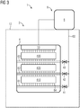
- Figure 3 shows another converter with a cooling device 1 according to a second embodiment of the present invention.
- the cooling device 1 in Figure 3 essentially comprises the elements of the Figure 2 shown cooling device.
- each of the cooling areas 410, 420, 430 is fluidically coupled to the line system 60 of the evaporative cooling device 6 via an associated line section 61, 62, 63.
- at least one control element 41, 42, 43 is provided for each line section 61, 62, 63.
- the control elements 41, 42, 43 are designed as control valves and are connected in parallel to the evaporative cooling device 6 with respect to the cooling fluid.
- the cooling device 1 has in addition to the cooling device Figure 2 horizontally and vertically extending fluid channels 64.
- the horizontal fluid channels 64 extend at least partially between the cooling regions 410, 420, 430.
- the present invention enables selective control or regulation of the cooling capacity within the cooling areas.
- the cooling areas are provided for electrical components of a converter that are subject to various losses. This improves the energetic efficiency of cooling a converter.
Description
Die Erfindung betrifft eine Kühlvorrichtung zur Kühlung elektrischer Komponenten eines Umrichters. Weiterhin betrifft die Erfindung einen Umrichter, der eine erfindungsgemäße Kühlvorrichtung umfasst. Ferner betrifft die Erfindung ein Verfahren zur Kühlung elektrischer Komponenten eines Umrichters.The invention relates to a cooling device for cooling electrical components of a converter. The invention also relates to a converter which comprises a cooling device according to the invention. The invention also relates to a method for cooling electrical components of a converter.
Typischerweise ergeben sich bei einem Betrieb eines Umrichters Verlustleistungen, welche auf dem begrenzten Wirkungsgrad der verwendeten elektrischen Komponenten des Umrichters zurückzuführen ist. Die größten Verlustleistungen weisen beispielsweise Wechselrichter, Symmetriewiderstände, Zwischenkreiskondensatoren oder Zusatzkomponenten, beispielsweise Gleichrichter, auf. Die elektrischen Komponenten erfordern folglich eine stetige Abfuhr der durch ihre Verlustleistung erzeugten Wärme, damit die Betriebssicherheit des Umrichters sichergestellt ist.Typically, there are power losses during operation of a converter, which can be attributed to the limited efficiency of the electrical components used in the converter. Inverters, symmetry resistors, intermediate circuit capacitors or additional components, for example rectifiers, have the greatest power losses. The electrical components consequently require a constant dissipation of the heat generated by their power loss so that the operational reliability of the converter is ensured.
Der Stand der Technik, wie beispielsweise
Aus dem Stand der Technik sind Umrichter bekannt, die mittels eines Thermosiphons gekühlt werden. Bei einem Thermosiphon wird die Verlustleistung dazu verwendet eine Flüssigkeit zu verdampfen. Durch die Verdampfung des Fluids wird den elektrischen Komponenten Wärme entzogen, wodurch diese gekühlt werden. Der durch die Verdampfung entstandene Dampf wird dann einem Wärmeübertrager zugeführt, der die Wärme durch eine Kondensation des Fluids an die Umgebung des Umrichters abgibt. Das kondensierte Fluid (Flüssigkeit) wird zu den zu kühlenden elektrischen Komponenten rückgeführt, sodass sich ein Kreislauf aus Verdampfung und Kondensation ausbildet. Zur Unterstützung des Kreislaufes, beispielsweise gegen die Erdbeschleunigung, kann dieser Kapillarstrukturen für das Fluid aufweisen.Converters which are cooled by means of a thermosiphon are known from the prior art. With a thermosiphon the power loss is used to evaporate a liquid. The evaporation of the fluid removes heat from the electrical components, thereby cooling them. The vapor generated by the evaporation is then fed to a heat exchanger, which releases the heat to the environment of the converter through condensation of the fluid. The condensed fluid (liquid) is returned to the electrical components to be cooled, so that a cycle of evaporation and condensation is formed. To support the circuit, for example against the acceleration of gravity, it can have capillary structures for the fluid.
Der vorliegenden Erfindung liegt die Aufgabe zugrunde eine Kühlvorrichtung zur Kühlung elektrischer Komponenten eines Umrichters bereitzustellen, die eine verbesserte Kühlung der genannten elektrischen Komponenten ermöglicht.The present invention is based on the object of providing a cooling device for cooling electrical components of a converter which enables improved cooling of the electrical components mentioned.
Die Aufgabe wird durch eine Kühlvorrichtung mit den Merkmalen des unabhängigen Patentanspruches 1, durch einen Umrichter mit den Merkmalen des unabhängigen Patentanspruches 10 sowie durch ein Verfahren mit den Merkmalen des unabhängigen Patenanspruches 12 gelöst. In den abhängigen Patentansprüchen sind vorteilhafte Ausgestaltungen und Weiterbildungen der Erfindung angegeben.The object is achieved by a cooling device with the features of independent patent claim 1, by a converter with the features of
Die erfindungsgemäße Kühlvorrichtung zur Kühlung elektrischer Komponenten eines Umrichters umfasst wenigstens eine Kühlplatte mit einem ersten und einem zweiten Kühlbereich, wobei die Kühlbereiche mit einer Siedekühlvorrichtung thermisch gekoppelt sind. Erfindungsgemäß weist die Kühlvorrichtung wenigstens ein erstes Steuerelement auf, mittels welchem die Kühlleistung der Siedekühlvorrichtung wenigstens eines der Kühlbereiche steuerbar ist.The cooling device according to the invention for cooling electrical components of a converter comprises at least one cooling plate with a first and a second cooling area, wherein the cooling areas are thermally coupled to a evaporative cooling device. According to the invention, the cooling device has at least one first control element, by means of which the cooling capacity of the evaporative cooling device of at least one of the cooling areas can be controlled.
Als elektrische Komponenten werden insbesondere alle Komponenten oder Bauelemente oder Bauteile eines Umrichters angesehen, die während eines Betriebes des Umrichters eine thermische Verlustleistung aufweisen und somit Wärme oder Abwärme erzeugen. Insbesondere werden elektronische Komponenten als elektrische Komponenten angesehen.In particular, all components or structural elements or parts of a converter that have a thermal power loss during operation of the converter and thus generate heat or waste heat are regarded as electrical components. In particular, electronic components are viewed as electrical components.
Eine Siedekühlvorrichtung im Sinne der vorliegenden Erfindung ist jede Vorrichtung, welche mittels eines Phasenübergangs eines Kühlfluids, beispielsweise einer Verdampfung oder einem Sieden eines Kühlfluids, zur Kühlung beziehungsweise zur Bereitstellung einer Kühlleistung für die Kühlbereiche geeignet ist.A evaporative cooling device within the meaning of the present invention is any device which by means of a phase transition a cooling fluid, for example evaporation or boiling of a cooling fluid, is suitable for cooling or for providing a cooling capacity for the cooling areas.
Die Kühlplatte beziehungsweise die zwei Kühlbereiche sind insbesondere zur Anordnung von zu kühlenden elektrischen Komponenten vorgesehen. Die elektrischen Komponenten können typischerweise in zwei Klassen eingeteilt werden, wobei die elektrischen Komponenten der erste Klasse eine vergleichsweise hohe Verlustleistung (verlustreiche Komponenten) und die elektrischen Komponenten der zweiten Klasse eine vergleichsweise geringe Verlustleitsung (verlustarme Komponenten) aufweist.The cooling plate or the two cooling areas are provided in particular for the arrangement of electrical components to be cooled. The electrical components can typically be divided into two classes, the electrical components of the first class having a comparatively high power loss (high-loss components) and the electrical components of the second class having a comparatively low power loss (low-loss components).
Vorteilhafterweise sind für eine Siedekühlvorrichtung keine bewegbaren Komponenten, beispielsweise Pumpen, erforderlich. Ein Vorteil der Siedekühlvorrichtung ist daher, dass diese sich typischerweise selbst steuert oder regelt. Beispielsweise wird mit steigender Verlustleistung mehr Dampf erzeugt. Dadurch erhöht sich der Druckverlust in den Leitungen der Siedekühlvorrichtung. Der erhöhte Druckverlust bedingt einen erhöhten Druck im Verdampfer der Siedekühlvorrichtung, so dass die Verdampfungstemperatur des Kühlfluids ansteigt. Die dadurch erhöhte Dampftemperatur erhöht gleichzeitig die Dichte des Dampfes, sodass sich der Druckverlust wieder reduziert. Weiterhin ist die Verdampfungstemperatur des Kühlfluids von der Kondensationstemperatur des Kühlfluids abhängig, die wiederum von der Temperatur des Kühlfluids an sich abhängt.Advantageously, no movable components, for example pumps, are required for a evaporative cooling device. One advantage of the evaporative cooling device is therefore that it typically controls or regulates itself. For example, more steam is generated with increasing power loss. This increases the pressure loss in the lines of the evaporative cooling device. The increased pressure loss causes an increased pressure in the evaporator of the evaporative cooling device, so that the evaporation temperature of the cooling fluid increases. The resulting increased steam temperature also increases the density of the steam, so that the pressure loss is reduced again. Furthermore, the evaporation temperature of the cooling fluid is dependent on the condensation temperature of the cooling fluid, which in turn depends on the temperature of the cooling fluid itself.
Erfindungsgemäß weist die Kühlvorrichtung die zwei Kühlbereiche auf. Hierbei kann erfindungsgemäß die Kühlleistung wenigstens eines der Kühlbereiche mittels des ersten Steuerelementes gesteuert werden. Dadurch ergeben sich zwei Kühlbereiche, die eine unterschiedliche Kühlleistung aufweisen können. Mit anderen Worten ist dadurch die Kühlleistung wenigstens eines der Kühlbereiche an die Verlustleistung der in diesem Kühlbereich angeordneten elektrischen Komponenten anpassbar.According to the invention, the cooling device has the two cooling areas. Here, according to the invention, the cooling performance of at least one of the cooling areas can be controlled by means of the first control element. This results in two cooling areas that can have different cooling capacities. In other words, this is at least the cooling capacity one of the cooling areas can be adapted to the power loss of the electrical components arranged in this cooling area.
Beispielsweise ist der erste Kühlbereich für elektrische Komponenten mit einer hohen Verlustleistung vorgesehen, wobei die Kühlleistung des ersten Kühlbereiches mittels des Steuerelementes steuerbar ist. Folglich kann die Kühlleistung für die verlustreichen elektrischen Komponenten mittels des Steuerelementes erhöht werden. Weiterhin kann die Kühlleistung der Siedekühlvorrichtung innerhalb des zweiten Kühlbereiches gegenüber dem ersten Kühlbereich geringer ausfallen. Insgesamt wird dadurch die Kühlung der elektrischen Komponenten des Umrichters mittels der erfindungsgemäßen Kühlvorrichtung effizienter. Mittels der erfindungsgemäßen Kühlvorrichtung wird es daher möglich die Kühlleistung der Siedekühlvorrichtung in wenigstens zwei Kühlbereichen der Kühlplatte zu steuern oder zu regeln. Dadurch kann die Temperatur in wenigstens einem der Kühlbereiche gesteuert und angepasst werden.For example, the first cooling area is provided for electrical components with a high power loss, the cooling power of the first cooling area being controllable by means of the control element. Consequently, the cooling capacity for the lossy electrical components can be increased by means of the control element. Furthermore, the cooling capacity of the evaporative cooling device within the second cooling area can be lower than in the first cooling area. Overall, this makes the cooling of the electrical components of the converter by means of the cooling device according to the invention more efficient. The cooling device according to the invention therefore makes it possible to control or regulate the cooling capacity of the evaporative cooling device in at least two cooling areas of the cooling plate. As a result, the temperature in at least one of the cooling areas can be controlled and adjusted.
Gemäß einer vorteilhaften Ausgestaltung der Erfindung umfasst die Kühlvorrichtung ein zweites Steuerelement, mittels welchem die Kühlleistung der Siedekühlvorrichtung des weiteren Kühlbereiches steuerbar ist.According to an advantageous embodiment of the invention, the cooling device comprises a second control element, by means of which the cooling capacity of the evaporative cooling device of the further cooling area can be controlled.
Vorteilhafterweise ist dadurch die Kühlleistung der Siedekühlvorrichtung in den zwei Kühlbereichen der Kühlvorrichtung steuerbar. Dadurch wird vorteilhafterweise die Effizienz der Kühlvorrichtung verbessert. Dass ist deshalb der Fall, da beispielsweise der erste Kühlbereich für verlustreiche elektrische Komponenten und der zweite Kühlbereich für verlustarme elektrische Komponenten vorgesehen ist und die jeweilige Kühlleistung auf die zu kühlenden Komponenten in den zwei Kühlbereichen getrennt voneinander anpassbar ist. Mit anderen Worten ist die Kühlleistung innerhalb der Kühlbereiche an die elektrische Verlustleistung der in den Kühlbereichen angeordneten elektrischen Komponenten anpassbar.The cooling output of the evaporative cooling device can thereby advantageously be controlled in the two cooling areas of the cooling device. This advantageously improves the efficiency of the cooling device. This is the case because, for example, the first cooling area is provided for high-loss electrical components and the second cooling area for low-loss electrical components and the respective cooling power can be adapted separately to the components to be cooled in the two cooling areas. In other words, the cooling power within the cooling areas can be adapted to the electrical power loss of the electrical components arranged in the cooling areas.
In einer vorteilhaften Weiterbildung der Erfindung ist die Siedekühlvorrichtung als ein Wärmerohr, insbesondere als eine Heat-Pipe oder ein Zweiphasen-Thermosiphon, ausgebildet.In an advantageous development of the invention, the evaporative cooling device is designed as a heat pipe, in particular as a heat pipe or a two-phase thermosiphon.
Dadurch wird vorteilhafterweise die Effizienz der Kühlvorrichtung weiter verbessert. Typischerweise weist ein Wärmerohr einen Verdampfer, einen Kondensator und ein Leitungssystem für ein Kühlfluid, welches innerhalb des Verdampfers verdampft, innerhalb des Kondensators kondensiert und mittels des Leitungssystems geführt wird, auf.This advantageously further improves the efficiency of the cooling device. Typically, a heat pipe has an evaporator, a condenser and a line system for a cooling fluid which evaporates inside the evaporator, condenses inside the condenser and is guided by means of the line system.
Es ist daher besonders bevorzugt, wenn die Siedekühlvorrichtung zwei Verdampfer zum Verdampfen des Kühlfluids aufweist, wobei die zwei Verdampfer wenigstens teilweise mittels der zwei Kühlbereiche der Kühlplatte ausgebildet sind.It is therefore particularly preferred if the evaporative cooling device has two evaporators for evaporating the cooling fluid, the two evaporators being formed at least partially by means of the two cooling areas of the cooling plate.
Mit anderen Worten wird das Kühlfluid durch die innerhalb der zwei Kühlbereiche angeordneten elektrischen Komponenten wenigstens teilweise zur Verdampfung gebracht. Der Dampf des Kühlfluids wird dann über das Leitungssystem zum Kondensator der Siedekühlvorrichtung geführt. Innerhalb des Kondensators der Siedekühlvorrichtung kondensiert das Kühlfluid wenigstens teilweise und gibt hierbei die durch seine Verdampfung aufgenommene Wärme, die der Verlustleistung der elektrischen Komponenten wenigstens teilweise entspricht, wenigstens teilweise an die Umgebung ab. Das kondensierte Kühlfluid wird dann wieder mittels des Leitungssystems zu den zwei Kühlbereichen der Kühlplatte rückgeführt. Hierbei weist die Siedekühlvorrichtung zwei Verdampfer und einen gemeinsamen Kondensator auf. Weiterhin sind die zwei Verdampfer und der gemeinsame Kondensator innerhalb eines gemeinsamen Leitungssystems angeordnet, wobei die zwei Verdampfer bezüglich des Massenstromes des Kühlfluids parallel verschaltet sind.In other words, the cooling fluid is at least partially caused to evaporate by the electrical components arranged within the two cooling areas. The vapor of the cooling fluid is then led to the condenser of the evaporative cooling device via the line system. The cooling fluid at least partially condenses inside the condenser of the evaporative cooling device and at least partially releases the heat absorbed by its evaporation, which corresponds at least partially to the power loss of the electrical components, to the environment. The condensed cooling fluid is then returned to the two cooling areas of the cooling plate again by means of the line system. Here, the evaporative cooling device has two evaporators and a common condenser. Furthermore, the two evaporators and the common condenser are arranged within a common line system, the two evaporators being connected in parallel with regard to the mass flow of the cooling fluid.
Hierbei kann die Siedetemperatur des Kühlfluids beispielsweise mittels einer Bimetall-Regelung innerhalb des Leitungsabschnittes des Dampfes gesteuert oder geregelt werden.In this case, the boiling temperature of the cooling fluid can be controlled or regulated, for example, by means of a bimetal regulator within the line section of the steam.
Gemäß einer vorteilhaften Ausgestaltung der Erfindung weist die Siedekühlvorrichtung ein Leitungssystem zur Führung des Kühlfluids auf, wobei das Leitungssystem einen für den ersten Kühlbereich ersten Leitungsabschnitt und einen für den zweiten Kühlbereich zweiten Leitungsabschnitt aufweist. Weiterhin ist hierbei die Kühlleistung des ersten Leitungsabschnittes mittels des ersten Steuerelementes und/oder die Kühlleistung des zweiten Leitungsabschnitts mittels des zweiten Steuerelementes steuerbar.According to an advantageous embodiment of the invention, the evaporative cooling device has a line system for guiding the cooling fluid, the line system having a first line section for the first cooling area and a second line section for the second cooling area. Furthermore, the cooling capacity of the first line section can be controlled by means of the first control element and / or the cooling capacity of the second line section can be controlled by means of the second control element.
Mit anderen Worten sind den Kühlbereichen der Kühlvorrichtung verschiedene Leistungsabschnitte des Leitungssystems zugeordnet. Mittels des ersten und/oder zweiten Steuerelementes ist die Kühlleistung der Leitungsabschnitte beispielsweise durch eine Anpassung des Massenstromes des Kühlfluides und/oder des Druckes des Kühlfluides, steuerbar. Hierbei ist der erste Leitungsabschnitt zur Führung des Kühlfluids zum ersten Kühlbereich und der zweite Leitungsabschnitt zur Führung des Kühlfluids zum zweiten Kühlbereich der Kühlvorrichtung ausgebildet. Innerhalb der Kühlbereiche verdampft dann das Kühlfluid wenigstens teilweise innerhalb der Leitungsabschnitte durch die in den Kühlbereichen mittels der elektrischen Komponenten erzeugte Wärme. Hierbei sind die Leitungsabschnitte bezüglich des Massenstromes des Kühlfluids typischerweise parallel geschaltet.In other words, different power sections of the line system are assigned to the cooling areas of the cooling device. By means of the first and / or second control element, the cooling performance of the line sections can be controlled, for example, by adapting the mass flow of the cooling fluid and / or the pressure of the cooling fluid. Here, the first line section is designed to guide the cooling fluid to the first cooling area and the second line section is designed to guide the cooling fluid to the second cooling area of the cooling device. Within the cooling areas, the cooling fluid then evaporates at least partially within the line sections due to the heat generated in the cooling areas by means of the electrical components. Here, the line sections are typically connected in parallel with respect to the mass flow of the cooling fluid.
In einer vorteilhaften Weiterbildung der Erfindung ist wenigstens eines der Steuerelemente als ein Steuerventil ausgebildet.In an advantageous development of the invention, at least one of the control elements is designed as a control valve.
Bevorzugt sind beide Steuerelemente, das heißt das erste und das zweite Steuerelement jeweils als ein Steuerventil ausgebildet. Mit anderen Worten trennt sich das Leitungssystem in den ersten und zweiten Leitungsabschnitt auf, wobei für jeden Leitungsabschnitt ein Steuerventil vorgesehen ist. Dadurch wird es möglich die Temperatur beziehungsweise die Kühlleistung innerhalb der Kühlbereiche zu steuern. Beispielsweise wird der Druckverlust innerhalb des Leitungsabschnittes, der für verlustärmere Komponenten vorgesehen ist, erhöht, wodurch weniger Kühlfluid durch den genannten Leitungsabschnitt fließt und somit die Kühlleistung reduziert wird. Mit anderen Worten wird hierbei das Steuerventil gedrosselt. Dadurch wird die Temperatur innerhalb des dem Leitungsabschnitt zugeordneten Kühlbereiches tendenziell erhöht. Werden beide Steuerventile gedrosselt, so steigt die Temperatur innerhalb der Kühlbereiche, da der Gesamtdruckverlust der Siedekühlvorrichtung ansteigt. Wurde ein Arbeitspunkt der Siedekühlvorrichtung unter Berücksichtigung einer teilweisen Drosselung der Steuerventile ausgelegt, so sinkt die Verdampfungstemperatur des Kühlfluids beim Öffnen der Steuerventile.Both control elements, that is to say the first and the second control element, are preferably each designed as a control valve. In other words, the line system is divided into the first and second line sections, a control valve being provided for each line section. This makes it possible to control the temperature or the cooling capacity within the cooling areas. For example, the pressure loss within the line section that is provided for lower-loss components, increased, whereby less cooling fluid flows through said line section and thus the cooling capacity is reduced. In other words, the control valve is throttled here. This tends to increase the temperature within the cooling area assigned to the line section. If both control valves are throttled, the temperature rises within the cooling areas because the total pressure loss of the evaporative cooling device increases. If an operating point of the evaporative cooling device was designed taking into account a partial throttling of the control valves, then the evaporation temperature of the cooling fluid drops when the control valves are opened.
Gemäß einer vorteilhaften Ausgestaltung der Erfindung umfasst die Kühlplatte die Leitungsabschnitte.According to an advantageous embodiment of the invention, the cooling plate comprises the line sections.
Dadurch wird vorteilhafterweise die thermische Kopplung zwischen der Kühlplatte und den Leitungsabschnitten und somit die thermischen Effizienz der Kühlvorrichtung verbessert.This advantageously improves the thermal coupling between the cooling plate and the line sections and thus the thermal efficiency of the cooling device.
Hierbei ist es besonders bevorzugt, wenn die Leitungsabschnitte mittels Bohrungen innerhalb der Kühlplatte ausgebildet sind.It is particularly preferred here if the line sections are formed by means of bores within the cooling plate.
Dadurch wird die thermische Kopplung zwischen der Kühlplatte und den Leitungsabschnitten beziehungsweise zwischen der Kühlplatte und dem Kühlfluid innerhalb der Leitungsabschnitte weiter verbessert.This further improves the thermal coupling between the cooling plate and the line sections or between the cooling plate and the cooling fluid within the line sections.
In einer vorteilhaften Weiterbildung der Erfindung weist wenigstens einer der Leitungsabschnitte eine Mehrzahl von bezüglich des Kühlfluids fluidisch parallel gekoppelten Fluidkanälen auf, wobei sich die Fluidkanäle räumlich parallel zueinander erstrecken.In an advantageous development of the invention, at least one of the line sections has a plurality of fluid channels that are fluidically coupled in parallel with respect to the cooling fluid, the fluid channels extending spatially parallel to one another.
Hierbei können die Fluidkanäle bevorzugt mittels Bohrungen innerhalb der Kühlplatte ausgebildet sein. Vorteilhafterweise wird das Kühlfluid durch die Fluidkanäle innerhalb der Kühlbereiche großflächig verteilt. Dadurch kann besonders viel Wärme abgeführt werden.Here, the fluid channels can preferably be formed by means of bores within the cooling plate. The cooling fluid is advantageously conveyed through the fluid channels within the cooling areas distributed over a large area. This allows a particularly large amount of heat to be dissipated.
Weiterhin werden elektrische Komponenten eines Umrichters typischerweise in verschiedenen geodätischen Höhen angeordnet. Da sich entlang der Kühlplatte der Druck des Kühlfluids ändert, ändert sich auch seine Verdampfungstemperatur entlang der Kühlplatte. Zusätzlich erhöht sich aufgrund der auf das Kühlfluid übertragenen thermischen Energie dessen Temperatur entlang der Kühlplatte. Zur Schaffung einer möglichst homogenen Temperatur- und Druckverteilung ist es daher von Vorteil die Mehrzahl von Fluidkanälen vorzusehen. Durch die Mehrzahl der Fluidkanäle, insbesondere der fluidisch parallel gekoppelten Fluidkanälen, kann der Massenstrom des Kühlfluids aktiv gesteuert werden und die Temperatur entlang der Kühlplatte annähernd konstant gehalten werden.Furthermore, electrical components of a converter are typically arranged at different geodetic heights. Since the pressure of the cooling fluid changes along the cooling plate, its evaporation temperature also changes along the cooling plate. In addition, the thermal energy transferred to the cooling fluid increases its temperature along the cooling plate. In order to create a temperature and pressure distribution that is as homogeneous as possible, it is therefore advantageous to provide the plurality of fluid channels. The mass flow of the cooling fluid can be actively controlled and the temperature along the cooling plate can be kept approximately constant through the plurality of fluid channels, in particular the fluid channels coupled fluidically in parallel.
Erfindungsgemäß ist die Kühlplatte wenigstens zweiteilig ausgebildet, wobei ein erster Teil der Kühlplatte den ersten Kühlbereich und ein zweiter Teil der Kühlplatte den zweiten Kühlbereich umfasst.According to the invention, the cooling plate is designed in at least two parts, a first part of the cooling plate comprising the first cooling area and a second part of the cooling plate comprising the second cooling area.
Dadurch ergibt sich vorteilhafterweise ein modularer Aufbau. Weiterhin wird die thermische Isolierung zwischen dem ersten Kühlbereich und dem zweiten Kühlbereich verbessert.This advantageously results in a modular structure. Furthermore, the thermal insulation between the first cooling area and the second cooling area is improved.
Der erfindungsgemäße Umrichter umfasst eine Kühlvorrichtung gemäß der vorliegenden Erfindung oder einer ihrer Ausgestaltungen.The converter according to the invention comprises a cooling device according to the present invention or one of its configurations.
Es ergeben sich zur bereits genannten erfindungsgemäßen Kühlvorrichtung gleichartige und gleichwertige Vorteile des erfindungsgemäßen Umrichters.Similar and equivalent advantages of the converter according to the invention result from the already mentioned cooling device according to the invention.
Besonders bevorzugt weist der Umrichter eine erste und zweite Klasse von elektrische Komponenten auf, wobei die erste Klasse von elektrischen Komponenten eine höhere thermische Verlustleistung als die zweite Klasse von elektrischen Komponenten aufweist und die Komponenten der ersten Klasse im ersten Kühlbereich und die Komponenten der zweiten Klasse im zweiten Kühlbereich angeordnet sind, wobei mittels des ersten Steuerelementes die Kühlleistung der Siedekühlvorrichtung innerhalb des ersten Kühlbereiches gegenüber der Kühlleistung der Siedekühlvorrichtung innerhalb des zweiten Kühlbereiches erhöhbar ist.The converter particularly preferably has a first and second class of electrical components, the first class of electrical components having a higher thermal power loss than the second class of electrical components and the components of the first class are arranged in the first cooling area and the components of the second class are arranged in the second cooling area, the cooling capacity of the evaporative cooling device within the first cooling area being able to be increased by means of the first control element compared to the cooling capacity of the evaporative cooling device within the second cooling area.
Mit anderen Worten ist der erste Kühlbereich der Kühlvorrichtung für die verlustreichen elektrischen Komponenten, beispielsweise Bipolartransistoren mit isolierter Gate-Elektrode (englisch: Insulated-Gate Bipolar Transistor, kurz IGBT), vorgesehen. Der zweite Kühlbereich der Kühlvorrichtung ist für verlustärmere elektrische Komponenten, beispielsweise Kondensatoren, vorgesehen. Dadurch wird vorteilhafterweise die Kühlleistung möglichst an die Verlustleistung der elektrischen Komponenten des Umrichters angepasst und somit optimiert. Dadurch wird die energetische Effizienz des Umrichters verbessert.In other words, the first cooling area of the cooling device is provided for the lossy electrical components, for example bipolar transistors with an insulated gate electrode (English: Insulated-Gate Bipolar Transistor, IGBT for short). The second cooling area of the cooling device is provided for electrical components with lower losses, for example capacitors. As a result, the cooling power is advantageously adapted as far as possible to the power loss of the electrical components of the converter and thus optimized. This improves the energy efficiency of the converter.
Hierbei wird das Kühlfluid beziehungsweise dessen Kondensat typischerweise über das Leitungssystem auf beide Kühlbereiche verteilt. Im Stand der Technik wird über die parallel kommunizierenden Fluidkanäle, die den Kühlbereichen zugeordnet sind, die Siedetemperatur des Kühlfluids innerhalb des Kühlbereiches, der für die verlustarmen Komponenten vorgesehen ist, durch die verlustreichen Komponenten beeinflusst und bestimmt. Zur Verhinderung dieser Beeinflussung ist erfindungsgemäß wenigstens das erste Steuerelement vorgesehen, mittels welchem die Kühlleistung innerhalb der Kühlbereiche getrennt voneinander steuerbar ist.Here, the cooling fluid or its condensate is typically distributed to both cooling areas via the line system. In the prior art, the boiling temperature of the cooling fluid within the cooling area, which is provided for the low-loss components, is influenced and determined by the high-loss components via the parallel communicating fluid channels that are assigned to the cooling areas. In order to prevent this influence, at least the first control element is provided according to the invention, by means of which the cooling performance within the cooling areas can be controlled separately from one another.
Das erfindungsgemäße Verfahren zur Kühlung elektrischer Komponenten eines Umrichters gemäß der vorliegenden Erfindung ist dadurch gekennzeichnet, dass mittels des ersten Steuerelementes der Kühlvorrichtung die Kühlleistung der Siedekühlvorrichtung wenigstens einer der Kühlbereiche gesteuert wird. Es ergeben sich zur erfindungsgemäßen Kühlvorrichtung sowie zum erfindungsgemäßen Umrichter gleichartige und gleichwertige Vorteile des erfindungsgemäßen Verfahrens.The method according to the invention for cooling electrical components of a converter according to the present invention is characterized in that the cooling power of the evaporative cooling device of at least one of the cooling areas is controlled by means of the first control element of the cooling device. Similar and equivalent advantages of the method according to the invention result for the cooling device according to the invention and for the converter according to the invention.
Hierbei ist es besonders bevorzugt, wenn als erstes und/oder zweites Steuerelement ein Steuerventil verwendet wird.It is particularly preferred here if a control valve is used as the first and / or second control element.
Weitere Vorteile, Merkmale und Einzelheiten der Erfindung ergeben sich aus dem im Folgenden beschriebenen Ausführungsbeispielen sowie anhand der Zeichnungen. Dabei zeigen schematisiert:
- Figur 1
- einen Umrichter mit einer aus dem Stand der Technik bekannten Siedekühlvorrichtung;
- Figur 2
- einen Umrichter mit einer Kühlvorrichtung gemäß einer ersten Ausgestaltung der vorliegenden Erfindung; und
- Figur 3
- einen weiteren Umrichter mit einer Kühlvorrichtung gemäß einer zweiten Ausgestaltung der vorliegenden Erfindung.
- Figure 1
- a converter with a evaporative cooling device known from the prior art;
- Figure 2
- an inverter having a cooling device according to a first aspect of the present invention; and
- Figure 3
- a further converter with a cooling device according to a second embodiment of the present invention.
Gleichartige, gleichwertige oder gleichwirkende Elemente können in den Figuren mit denselben Bezugszeichen versehen sein.Identical, equivalent or identically acting elements can be provided with the same reference symbols in the figures.
Innerhalb eines Schrankes 12 des Umrichters 2 ist eine Kühlplatte 4 angeordnet. Die Kühlplatte 4 ist zur Anordnung elektrischer Komponenten vorgesehen sowie zu deren Kühlung. Hierzu ist die Kühlplatte 4 mit dem Leitungssystem 60 der Siedekühlvorrichtung 6 thermisch gekoppelt. Weiterhin weist die Kühlplatte 4 zur Kühlung der elektrischen Komponenten eine Mehrzahl von Fluidkanälen 64 auf, die bezüglich eines Kühlfluids innerhalb des Leitungssystems 60 fluidisch parallel verschaltet sind.A
Die aus dem Stand der Technik bekannte Kühlvorrichtung 1 weist zwei Kühlbereiche 410, 420 auf, innerhalb welcher elektrische Komponenten unterschiedlicher Verlustleistung angeordnet sind oder werden. Innerhalb des ersten Kühlbereiches 410 sind beispielsweise verlustreiche elektrische Komponenten, insbesondere IGBTs angeordnet. Innerhalb des zweiten Kühlbereiches 420 sind dann vergleichsweise verlustarme elektrische Komponenten, beispielsweise Kondensatoren, angeordnet. Zur Kühlung der Kühlbereiche 410, 420 sind die Fluidkanäle 64 vorgesehen, die thermisch mit den Kühlbereichen 410, 420 gekoppelt sind und sich durch diese erstrecken.The cooling device 1 known from the prior art has two cooling
Nachteilig am dargestellten Stand der Technik ist, dass es erforderlich ist die Kühlleistung innerhalb der Kühlbereiche 410, 420, die von der Siedekühlvorrichtung 6 bereitgestellt wird, an den verlustreichen Komponenten des ersten Kühlbereiches 410 auszulegen.The disadvantage of the prior art shown is that it is necessary to design the cooling power within the cooling
Zur Überwindung dieses Nachteils zeigt
Die Kühlvorrichtung 1 umfasst wiederum einen Kondensator 8, ein Leitungssystem 60, eine Kühlplatte 4 sowie zwei Kühlbereiche 410, 420. Weiterhin ist ein Dampfsammler 10 zum Sammeln des verdampften Kühlfluids und zur Rückführung des verdampften Kühlfluids zum Kondensator 8 vorgesehen.The cooling device 1 in turn comprises a
Wie bereits in
Weiterhin weist das Leitungssystem 60 einen ersten Leitungsabschnitt 61 sowie einen zweiten Leitungsabschnitt 62 auf. Der Druck und/oder der Massenstrom des Kühlfluids innerhalb des ersten Leitungsabschnittes 61 kann mittels des ersten Steuerelementes 41 gesteuert oder geregelt werden. Analog kann der Druck und/oder der Massenstrom des Kühlfluids innerhalb des zweiten Leitungsabschnittes 62 mittels des zweiten Steuerelementes 42 gesteuert oder geregelt werden.Furthermore, the
Dadurch wird es vorteilhafterweise möglich, die Kühlleistung der Siedekühlvorrichtung 6 innerhalb des ersten Kühlbereiches 410 und innerhalb des zweiten Kühlbereiches 420 zu steuern oder zu regeln. Beispielsweise wird die Kühlleistung des Siedekühlvorrichtung 6 innerhalb des ersten Kühlbereiches 410 gegenüber der Kühlleistung der Siedekühlvorrichtung innerhalb des zweiten Kühlbereiches 420 erhöht. Mit anderen Worten ist der erste Kühlbereich 410 für verlustreiche elektrische Komponenten und der zweite Kühlbereich 420 für verlustarme elektrische Komponenten des Umrichters 2 vorgesehen.This advantageously makes it possible to control or regulate the cooling capacity of the evaporative cooling device 6 within the
Zur Verteilung des flüssigen Kühlfluids innerhalb der Kühlbereiche 410, 420 ist eine Mehrzahl von Fluidkanälen 64 vorgesehen. Hierbei sind die Fluidkanäle 64 jeweils mit dem zugehörigen Leitungsabschnitt 61, 62 fluidisch gekoppelt. Zur Veranschaulichung ist nur einer der Fluidkanäle mit dem Bezugszeichen 64 gekennzeichnet. Die Fluidkanäle 64 erstrecken sich innerhalb ihres jeweiligen Kühlbereiches 410, 420 annähernd räumlich parallel zueinander. Eine räumlich mäanderförmige Erstreckung der Kühlkanäle 64 innerhalb der Kühlbereiche 410, 420 kann vorgesehen sein. Die Fluidkanäle 64 erstrecken sich in der dargestellten
In
Die Kühlvorrichtung 1 in
Ergänzend zu
Weiterhin weist die Kühlvorrichtung 1 ergänzend zur Kühlvorrichtung aus
Durch die vorliegende Erfindung wird eine selektive Steuerung oder Regelung der Kühlleistung innerhalb der Kühlbereiche ermöglicht. Hierbei sind die Kühlbereiche für verschieden verlustbehaftete elektrische Komponenten eines Umrichters vorgesehen. Dadurch wird die energetische Effizienz der Kühlung eines Umrichters verbessert.The present invention enables selective control or regulation of the cooling capacity within the cooling areas. Here, the cooling areas are provided for electrical components of a converter that are subject to various losses. This improves the energetic efficiency of cooling a converter.
Obwohl die Erfindung im Detail durch die bevorzugten Ausführungsbeispiele näher illustriert und beschrieben wurde, so ist die Erfindung nicht durch die offenbarten Beispiele eingeschränkt oder andere Variationen können vom Fachmann hieraus abgeleitet werden, ohne den Schutzumfang der Erfindung gemäß den Ansprüchen zu verlassen.Although the invention has been illustrated and described in more detail by the preferred exemplary embodiments, the invention is not restricted by the examples disclosed or other variations can be derived therefrom by the person skilled in the art without departing from the scope of protection of the invention according to the claims.
Claims (14)
- Cooling apparatus (1) for cooling electrical components of a converter (2), comprising at least one cooling plate (4) with a first and second cooling region (410, 420), wherein the cooling plate (4) is embodied in at least two parts, and a first part of the cooling plate comprises the first cooling region (410) and a second part of the cooling plate (4) the second cooling region (420), wherein the cooling regions (410, 420) are thermally coupled to an evaporative cooling apparatus (6) comprising a pipe system (60) and a condenser (8), and the cooling apparatus (1) has at least a first control element (41), by means of which the cooling capacity of the evaporative cooling apparatus (6) of at least one of the cooling regions (410) is able to be controlled, wherein the cooling plate (2) comprises a steam collector 10 for collecting evaporated cooling fluid and for guiding the evaporated cooling fluid back to the condenser 8.
- Cooling apparatus (1) according to claim 1, characterised in that it comprises a second control element (42), by means of which the cooling capacity of the evaporative cooling apparatus (6) of the further cooling region (420) is able to be controlled.
- Cooling apparatus (1) according to claim 1 or 2, characterised in that the evaporative cooling apparatus (6) is embodied as a thermal pipe, in particular as a heat pipe or a two-phase thermosiphon.
- Cooling apparatus (1) according to claim 3, characterised in that the evaporative cooling apparatus (6) has two evaporators for evaporating a cooling fluid, wherein the two evaporators are at least partially embodied by means of the two cooling regions (410, 420) of the cooling plate (4).
- Cooling apparatus (1) according to claim 4, characterised in that the evaporative cooling apparatus (6) has a pipe system (60) for guiding the cooling fluid, wherein the pipe system (60) has a first line section (61) for the first cooling region (410) and a second line section (62) for the second cooling region (420), wherein the cooling capacity of the first line section (61) is able to be controlled by means of the first control element (41) and/or the cooling capacity of the second line section (62) is able to be controlled by means of the second control element (42).
- Cooling apparatus (1) according to claim 5, characterised in that at least one of the control elements (41, 42) is embodied as a control valve.
- Cooling apparatus (1) according to one of claims 4 to 6, characterised in that the cooling plate (4) comprises the line sections (61, 62).
- Cooling apparatus (1) according to claim 7, characterised in that the line sections (61, 62) are embodied by means of bore holes within the cooling plate (4).
- Cooling apparatus (1) according to one of claims 5 to 8, characterised in that at least one of the line sections (61, 62) has a plurality of fluid ducts (63) which are fluidically coupled in parallel in relation to the cooling fluid, wherein the fluid ducts (63) extend in parallel with one another spatially.
- Converter (2), characterised in that it comprises at least one cooling apparatus (1) according to one of the preceding claims.
- Converter (2) according to claim 10, characterised in that it has a first and second class of electrical components, wherein the first class of electrical components has a higher thermal power loss than the second class of electrical components, and the components of the first class are arranged in the first cooling region (410) and the components of the second class in the second cooling region (420), wherein the first control element (41) can be used to increase the cooling capacity of the evaporative cooling apparatus (6) within the first cooling region (410) compared to the cooling capacity of the evaporative cooling apparatus (6) within the second cooling region (420).
- Method for cooling electrical components of a converter (2), with a converter according to claim 10 or 11, characterised in that the cooling capacity of the evaporative cooling apparatus (6) of at least one of the cooling regions (410) is controlled by means of the first control element (41) of the cooling apparatus (1).
- Method according to claim 12, characterised in that the cooling capacity of the evaporative cooling apparatus (6) of the further cooling region (420) is controlled by means of the second control element (42) of the cooling apparatus (1).
- Method according to claim 12 or 13, characterised in that a control valve is used as the first and/or second control element (41, 42).
Applications Claiming Priority (2)
| Application Number | Priority Date | Filing Date | Title |
|---|---|---|---|
| EP17156233.3A EP3364735A1 (en) | 2017-02-15 | 2017-02-15 | Cooling device, converter with a cooling device and method for cooling a converter |
| PCT/EP2017/078393 WO2018149522A1 (en) | 2017-02-15 | 2017-11-07 | Cooling device, converter comprising a cooling device, and method for cooling a converter |
Publications (2)
| Publication Number | Publication Date |
|---|---|
| EP3563650A1 EP3563650A1 (en) | 2019-11-06 |
| EP3563650B1 true EP3563650B1 (en) | 2021-01-06 |
Family
ID=58056985
Family Applications (2)
| Application Number | Title | Priority Date | Filing Date |
|---|---|---|---|
| EP17156233.3A Withdrawn EP3364735A1 (en) | 2017-02-15 | 2017-02-15 | Cooling device, converter with a cooling device and method for cooling a converter |
| EP17804819.5A Active EP3563650B1 (en) | 2017-02-15 | 2017-11-07 | Cooling device, converter with a cooling device and method for cooling a converter |
Family Applications Before (1)
| Application Number | Title | Priority Date | Filing Date |
|---|---|---|---|
| EP17156233.3A Withdrawn EP3364735A1 (en) | 2017-02-15 | 2017-02-15 | Cooling device, converter with a cooling device and method for cooling a converter |
Country Status (6)
| Country | Link |
|---|---|
| US (1) | US20200053917A1 (en) |
| EP (2) | EP3364735A1 (en) |
| CN (1) | CN110301169B (en) |
| DK (1) | DK3563650T3 (en) |
| RU (1) | RU2718760C1 (en) |
| WO (1) | WO2018149522A1 (en) |
Families Citing this family (2)
| Publication number | Priority date | Publication date | Assignee | Title |
|---|---|---|---|---|
| DE102019133952A1 (en) * | 2019-12-11 | 2021-06-17 | Semikron Elektronik Gmbh & Co. Kg | Power electronic system with a housing, a cooling device, a power semiconductor module and a capacitor device |
| US11856687B2 (en) | 2021-12-21 | 2023-12-26 | Semikron Elektronik Gmbh & Co. Kg | Power electronics system having a housing, a cooling device, a power semiconductor module and a capacitor device |
Citations (1)
| Publication number | Priority date | Publication date | Assignee | Title |
|---|---|---|---|---|
| US20110277967A1 (en) * | 2007-04-16 | 2011-11-17 | Stephen Samuel Fried | Liquid cooled condensers for loop heat pipe like enclosure cooling |
Family Cites Families (20)
| Publication number | Priority date | Publication date | Assignee | Title |
|---|---|---|---|---|
| US6490160B2 (en) * | 1999-07-15 | 2002-12-03 | Incep Technologies, Inc. | Vapor chamber with integrated pin array |
| US7032389B2 (en) * | 2003-12-12 | 2006-04-25 | Thermoelectric Design, Llc | Thermoelectric heat pump with direct cold sink support |
| US7327578B2 (en) * | 2004-02-06 | 2008-02-05 | Sun Microsystems, Inc. | Cooling failure mitigation for an electronics enclosure |
| US7203063B2 (en) * | 2004-05-21 | 2007-04-10 | Hewlett-Packard Development Company, L.P. | Small form factor liquid loop cooling system |
| US20060278370A1 (en) * | 2005-06-08 | 2006-12-14 | Uwe Rockenfeller | Heat spreader for cooling electronic components |
| KR100772381B1 (en) * | 2005-09-29 | 2007-11-01 | 삼성전자주식회사 | Heat sink |
| CN101336358B (en) * | 2005-12-22 | 2012-07-18 | 奥克西康比希尔公司 | Evaporative cooling device |
| EP2031332B1 (en) * | 2007-08-27 | 2010-09-15 | ABB Research LTD | Heat exchanger for power-electronics components |
| US7855397B2 (en) * | 2007-09-14 | 2010-12-21 | Nextreme Thermal Solutions, Inc. | Electronic assemblies providing active side heat pumping |
| US9025330B2 (en) * | 2007-09-30 | 2015-05-05 | Alcatel Lucent | Recirculating gas rack cooling architecture |
| US20130192272A1 (en) * | 2008-10-23 | 2013-08-01 | Gentherm Incorporated | Temperature control systems with thermoelectric devices |
| US7969733B1 (en) * | 2008-12-17 | 2011-06-28 | Nvidia Corporation | Heat transfer system, method, and computer program product for use with multiple circuit board environments |
| US20100281884A1 (en) * | 2009-01-22 | 2010-11-11 | John Myron Rawski | Thermoelectric Management Unit |
| US9151540B2 (en) * | 2010-06-29 | 2015-10-06 | Johnson Controls Technology Company | Multichannel heat exchanger tubes with flow path inlet sections |
| RU2014150083A (en) * | 2012-05-11 | 2016-07-10 | Дантхерм Кулинг А/С | VARIABLE CONDUCTIVITY THERMOSIPHONE |
| EP2734020B1 (en) * | 2012-11-19 | 2017-07-12 | ABB Schweiz AG | Cooling arrangement with a two-phase thermosyphon for cooling a multiplicity of electric devices |
| CN104427825B (en) * | 2013-08-28 | 2020-01-17 | 北京航空航天大学 | Multi-connected variable-frequency refrigeration system for fixed-point cooling of multiple heat dissipation sources of electronic equipment and operation method of multi-connected variable-frequency refrigeration system |
| CN104362837B (en) * | 2014-11-25 | 2016-11-09 | 南车株洲电力机车研究所有限公司 | A kind of current transformer cooling system |
| KR102398882B1 (en) * | 2017-05-30 | 2022-05-18 | 현대자동차주식회사 | Power generation module of air-conditioning system for vehicle |
| US10602638B2 (en) * | 2018-03-01 | 2020-03-24 | Dell Products L.P. | System and method of transferring energy |
-
2017
- 2017-02-15 EP EP17156233.3A patent/EP3364735A1/en not_active Withdrawn
- 2017-11-07 EP EP17804819.5A patent/EP3563650B1/en active Active
- 2017-11-07 WO PCT/EP2017/078393 patent/WO2018149522A1/en unknown
- 2017-11-07 RU RU2019125619A patent/RU2718760C1/en active
- 2017-11-07 DK DK17804819.5T patent/DK3563650T3/en active
- 2017-11-07 CN CN201780086405.3A patent/CN110301169B/en active Active
- 2017-11-07 US US16/486,014 patent/US20200053917A1/en not_active Abandoned
Patent Citations (1)
| Publication number | Priority date | Publication date | Assignee | Title |
|---|---|---|---|---|
| US20110277967A1 (en) * | 2007-04-16 | 2011-11-17 | Stephen Samuel Fried | Liquid cooled condensers for loop heat pipe like enclosure cooling |
Also Published As
| Publication number | Publication date |
|---|---|
| EP3563650A1 (en) | 2019-11-06 |
| WO2018149522A1 (en) | 2018-08-23 |
| US20200053917A1 (en) | 2020-02-13 |
| CN110301169A (en) | 2019-10-01 |
| DK3563650T3 (en) | 2021-03-22 |
| EP3364735A1 (en) | 2018-08-22 |
| CN110301169B (en) | 2021-06-11 |
| RU2718760C1 (en) | 2020-04-14 |
Similar Documents
| Publication | Publication Date | Title |
|---|---|---|
| DE60125085T2 (en) | Inflatable liquid cooling system with phase change cooling | |
| EP2059104A2 (en) | Cooling device for a computer system | |
| WO2012110461A1 (en) | Room air conditioner having a liquid-to-air heat exchanging device having peltier elements | |
| DE102016200744A1 (en) | Transformer with temperature-dependent cooling | |
| EP2557676A1 (en) | Converter device with an air cooling system | |
| EP3563650B1 (en) | Cooling device, converter with a cooling device and method for cooling a converter | |
| WO2020099229A1 (en) | Fuel cell device and method for cooling a fuel cell system | |
| DE102008044645B3 (en) | An aircraft signal computer system comprising a plurality of modular signal processor units | |
| EP2392202A1 (en) | Method and arrangement for cooling electrical and electronic components and module units in electrical enclosures | |
| EP2662871A2 (en) | Assembly with a transformer | |
| EP2709152A2 (en) | Cooling circuit with sufficiently small dimensioned heat exchanger | |
| EP3036763B1 (en) | Cooling device for a current converter module | |
| WO2008040596A2 (en) | Heat sink for cooling an electrical component | |
| WO2009036913A1 (en) | High-temperature polymer electrolyte membrane fuel cell (ht-pemfc) including apparatuses for cooling said fuel cell | |
| DE202013004551U1 (en) | IGBT converter unit with cooling system and control cabinet for such an IGBT inverter unit | |
| EP3379191B1 (en) | Thermal storage device and method for operating a thermal storage device | |
| DE102014105051A1 (en) | Method and device for operating an electronic circuit in a control cabinet | |
| EP4035511A2 (en) | Electrical enclosure assembly with at least one it rack or electrical enclosure housing and with at least one cooling device, and corresponding method | |
| EP2677244B1 (en) | Humidifier | |
| DE19960841A1 (en) | Power converter device with a two-phase heat transfer device | |
| EP3490355A1 (en) | Modular converter | |
| DE202015009294U1 (en) | Ladder rail arrangement and switchgear | |
| DE102015202487A1 (en) | ENERGY CONVERSION DEVICE AND RAIL VEHICLE EQUIPPED WITH THE SAME | |
| DE3132112A1 (en) | Cooling device for circuit elements which produce heat | |
| DE102013213464A1 (en) | Induction heating device for use in induction hob, has heat pipe that is arranged between heat sources and heat sink, for radiating heat from heat sink to heat sources |
Legal Events
| Date | Code | Title | Description |
|---|---|---|---|
| STAA | Information on the status of an ep patent application or granted ep patent |
Free format text: STATUS: UNKNOWN |
|
| STAA | Information on the status of an ep patent application or granted ep patent |
Free format text: STATUS: THE INTERNATIONAL PUBLICATION HAS BEEN MADE |
|
| PUAI | Public reference made under article 153(3) epc to a published international application that has entered the european phase |
Free format text: ORIGINAL CODE: 0009012 |
|
| STAA | Information on the status of an ep patent application or granted ep patent |
Free format text: STATUS: REQUEST FOR EXAMINATION WAS MADE |
|
| 17P | Request for examination filed |
Effective date: 20190731 |
|
| AK | Designated contracting states |
Kind code of ref document: A1 Designated state(s): AL AT BE BG CH CY CZ DE DK EE ES FI FR GB GR HR HU IE IS IT LI LT LU LV MC MK MT NL NO PL PT RO RS SE SI SK SM TR |
|
| AX | Request for extension of the european patent |
Extension state: BA ME |
|
| DAV | Request for validation of the european patent (deleted) | ||
| DAX | Request for extension of the european patent (deleted) | ||
| GRAJ | Information related to disapproval of communication of intention to grant by the applicant or resumption of examination proceedings by the epo deleted |
Free format text: ORIGINAL CODE: EPIDOSDIGR1 |
|
| STAA | Information on the status of an ep patent application or granted ep patent |
Free format text: STATUS: GRANT OF PATENT IS INTENDED |
|
| GRAP | Despatch of communication of intention to grant a patent |
Free format text: ORIGINAL CODE: EPIDOSNIGR1 |
|
| INTG | Intention to grant announced |
Effective date: 20200911 |
|
| GRAS | Grant fee paid |
Free format text: ORIGINAL CODE: EPIDOSNIGR3 |
|
| GRAA | (expected) grant |
Free format text: ORIGINAL CODE: 0009210 |
|
| STAA | Information on the status of an ep patent application or granted ep patent |
Free format text: STATUS: THE PATENT HAS BEEN GRANTED |
|
| AK | Designated contracting states |
Kind code of ref document: B1 Designated state(s): AL AT BE BG CH CY CZ DE DK EE ES FI FR GB GR HR HU IE IS IT LI LT LU LV MC MK MT NL NO PL PT RO RS SE SI SK SM TR |
|
| REG | Reference to a national code |
Ref country code: GB Ref legal event code: FG4D Free format text: NOT ENGLISH |
|
| REG | Reference to a national code |
Ref country code: AT Ref legal event code: REF Ref document number: 1353790 Country of ref document: AT Kind code of ref document: T Effective date: 20210115 Ref country code: CH Ref legal event code: EP |
|
| REG | Reference to a national code |
Ref country code: DE Ref legal event code: R096 Ref document number: 502017009005 Country of ref document: DE |
|
| REG | Reference to a national code |
Ref country code: IE Ref legal event code: FG4D Free format text: LANGUAGE OF EP DOCUMENT: GERMAN |
|
| REG | Reference to a national code |
Ref country code: DK Ref legal event code: T3 Effective date: 20210317 |
|
| REG | Reference to a national code |
Ref country code: SE Ref legal event code: TRGR |
|
| REG | Reference to a national code |
Ref country code: NL Ref legal event code: MP Effective date: 20210106 |
|
| REG | Reference to a national code |
Ref country code: LT Ref legal event code: MG9D |
|
| PG25 | Lapsed in a contracting state [announced via postgrant information from national office to epo] |
Ref country code: NO Free format text: LAPSE BECAUSE OF FAILURE TO SUBMIT A TRANSLATION OF THE DESCRIPTION OR TO PAY THE FEE WITHIN THE PRESCRIBED TIME-LIMIT Effective date: 20210406 Ref country code: PT Free format text: LAPSE BECAUSE OF FAILURE TO SUBMIT A TRANSLATION OF THE DESCRIPTION OR TO PAY THE FEE WITHIN THE PRESCRIBED TIME-LIMIT Effective date: 20210506 Ref country code: GR Free format text: LAPSE BECAUSE OF FAILURE TO SUBMIT A TRANSLATION OF THE DESCRIPTION OR TO PAY THE FEE WITHIN THE PRESCRIBED TIME-LIMIT Effective date: 20210407 Ref country code: HR Free format text: LAPSE BECAUSE OF FAILURE TO SUBMIT A TRANSLATION OF THE DESCRIPTION OR TO PAY THE FEE WITHIN THE PRESCRIBED TIME-LIMIT Effective date: 20210106 Ref country code: FI Free format text: LAPSE BECAUSE OF FAILURE TO SUBMIT A TRANSLATION OF THE DESCRIPTION OR TO PAY THE FEE WITHIN THE PRESCRIBED TIME-LIMIT Effective date: 20210106 Ref country code: LT Free format text: LAPSE BECAUSE OF FAILURE TO SUBMIT A TRANSLATION OF THE DESCRIPTION OR TO PAY THE FEE WITHIN THE PRESCRIBED TIME-LIMIT Effective date: 20210106 Ref country code: BG Free format text: LAPSE BECAUSE OF FAILURE TO SUBMIT A TRANSLATION OF THE DESCRIPTION OR TO PAY THE FEE WITHIN THE PRESCRIBED TIME-LIMIT Effective date: 20210406 |
|
| PG25 | Lapsed in a contracting state [announced via postgrant information from national office to epo] |
Ref country code: PL Free format text: LAPSE BECAUSE OF FAILURE TO SUBMIT A TRANSLATION OF THE DESCRIPTION OR TO PAY THE FEE WITHIN THE PRESCRIBED TIME-LIMIT Effective date: 20210106 Ref country code: RS Free format text: LAPSE BECAUSE OF FAILURE TO SUBMIT A TRANSLATION OF THE DESCRIPTION OR TO PAY THE FEE WITHIN THE PRESCRIBED TIME-LIMIT Effective date: 20210106 Ref country code: LV Free format text: LAPSE BECAUSE OF FAILURE TO SUBMIT A TRANSLATION OF THE DESCRIPTION OR TO PAY THE FEE WITHIN THE PRESCRIBED TIME-LIMIT Effective date: 20210106 |
|
| PG25 | Lapsed in a contracting state [announced via postgrant information from national office to epo] |
Ref country code: IS Free format text: LAPSE BECAUSE OF FAILURE TO SUBMIT A TRANSLATION OF THE DESCRIPTION OR TO PAY THE FEE WITHIN THE PRESCRIBED TIME-LIMIT Effective date: 20210506 |
|
| REG | Reference to a national code |
Ref country code: DE Ref legal event code: R097 Ref document number: 502017009005 Country of ref document: DE |
|
| PG25 | Lapsed in a contracting state [announced via postgrant information from national office to epo] |
Ref country code: EE Free format text: LAPSE BECAUSE OF FAILURE TO SUBMIT A TRANSLATION OF THE DESCRIPTION OR TO PAY THE FEE WITHIN THE PRESCRIBED TIME-LIMIT Effective date: 20210106 Ref country code: CZ Free format text: LAPSE BECAUSE OF FAILURE TO SUBMIT A TRANSLATION OF THE DESCRIPTION OR TO PAY THE FEE WITHIN THE PRESCRIBED TIME-LIMIT Effective date: 20210106 Ref country code: SM Free format text: LAPSE BECAUSE OF FAILURE TO SUBMIT A TRANSLATION OF THE DESCRIPTION OR TO PAY THE FEE WITHIN THE PRESCRIBED TIME-LIMIT Effective date: 20210106 |
|
| PLBE | No opposition filed within time limit |
Free format text: ORIGINAL CODE: 0009261 |
|
| STAA | Information on the status of an ep patent application or granted ep patent |
Free format text: STATUS: NO OPPOSITION FILED WITHIN TIME LIMIT |
|
| PG25 | Lapsed in a contracting state [announced via postgrant information from national office to epo] |
Ref country code: SK Free format text: LAPSE BECAUSE OF FAILURE TO SUBMIT A TRANSLATION OF THE DESCRIPTION OR TO PAY THE FEE WITHIN THE PRESCRIBED TIME-LIMIT Effective date: 20210106 Ref country code: RO Free format text: LAPSE BECAUSE OF FAILURE TO SUBMIT A TRANSLATION OF THE DESCRIPTION OR TO PAY THE FEE WITHIN THE PRESCRIBED TIME-LIMIT Effective date: 20210106 |
|
| 26N | No opposition filed |
Effective date: 20211007 |
|
| PG25 | Lapsed in a contracting state [announced via postgrant information from national office to epo] |
Ref country code: AL Free format text: LAPSE BECAUSE OF FAILURE TO SUBMIT A TRANSLATION OF THE DESCRIPTION OR TO PAY THE FEE WITHIN THE PRESCRIBED TIME-LIMIT Effective date: 20210106 Ref country code: ES Free format text: LAPSE BECAUSE OF FAILURE TO SUBMIT A TRANSLATION OF THE DESCRIPTION OR TO PAY THE FEE WITHIN THE PRESCRIBED TIME-LIMIT Effective date: 20210106 |
|
| PG25 | Lapsed in a contracting state [announced via postgrant information from national office to epo] |
Ref country code: SI Free format text: LAPSE BECAUSE OF FAILURE TO SUBMIT A TRANSLATION OF THE DESCRIPTION OR TO PAY THE FEE WITHIN THE PRESCRIBED TIME-LIMIT Effective date: 20210106 |
|
| PG25 | Lapsed in a contracting state [announced via postgrant information from national office to epo] |
Ref country code: IS Free format text: LAPSE BECAUSE OF FAILURE TO SUBMIT A TRANSLATION OF THE DESCRIPTION OR TO PAY THE FEE WITHIN THE PRESCRIBED TIME-LIMIT Effective date: 20210506 |
|
| PG25 | Lapsed in a contracting state [announced via postgrant information from national office to epo] |
Ref country code: MC Free format text: LAPSE BECAUSE OF FAILURE TO SUBMIT A TRANSLATION OF THE DESCRIPTION OR TO PAY THE FEE WITHIN THE PRESCRIBED TIME-LIMIT Effective date: 20210106 |
|
| REG | Reference to a national code |
Ref country code: CH Ref legal event code: PL |
|
| GBPC | Gb: european patent ceased through non-payment of renewal fee |
Effective date: 20211107 |
|
| PG25 | Lapsed in a contracting state [announced via postgrant information from national office to epo] |
Ref country code: LU Free format text: LAPSE BECAUSE OF NON-PAYMENT OF DUE FEES Effective date: 20211107 Ref country code: BE Free format text: LAPSE BECAUSE OF NON-PAYMENT OF DUE FEES Effective date: 20211130 |
|
| REG | Reference to a national code |
Ref country code: BE Ref legal event code: MM Effective date: 20211130 |
|
| PG25 | Lapsed in a contracting state [announced via postgrant information from national office to epo] |
Ref country code: LI Free format text: LAPSE BECAUSE OF NON-PAYMENT OF DUE FEES Effective date: 20211130 Ref country code: CH Free format text: LAPSE BECAUSE OF NON-PAYMENT OF DUE FEES Effective date: 20211130 |
|
| PG25 | Lapsed in a contracting state [announced via postgrant information from national office to epo] |
Ref country code: IE Free format text: LAPSE BECAUSE OF NON-PAYMENT OF DUE FEES Effective date: 20211107 Ref country code: GB Free format text: LAPSE BECAUSE OF NON-PAYMENT OF DUE FEES Effective date: 20211107 |
|
| PGFP | Annual fee paid to national office [announced via postgrant information from national office to epo] |
Ref country code: DE Payment date: 20230119 Year of fee payment: 6 |
|
| PG25 | Lapsed in a contracting state [announced via postgrant information from national office to epo] |
Ref country code: NL Free format text: LAPSE BECAUSE OF NON-PAYMENT OF DUE FEES Effective date: 20210206 Ref country code: CY Free format text: LAPSE BECAUSE OF FAILURE TO SUBMIT A TRANSLATION OF THE DESCRIPTION OR TO PAY THE FEE WITHIN THE PRESCRIBED TIME-LIMIT Effective date: 20210106 |
|
| PG25 | Lapsed in a contracting state [announced via postgrant information from national office to epo] |
Ref country code: HU Free format text: LAPSE BECAUSE OF FAILURE TO SUBMIT A TRANSLATION OF THE DESCRIPTION OR TO PAY THE FEE WITHIN THE PRESCRIBED TIME-LIMIT; INVALID AB INITIO Effective date: 20171107 |
|
| REG | Reference to a national code |
Ref country code: AT Ref legal event code: MM01 Ref document number: 1353790 Country of ref document: AT Kind code of ref document: T Effective date: 20221107 |
|
| PG25 | Lapsed in a contracting state [announced via postgrant information from national office to epo] |
Ref country code: AT Free format text: LAPSE BECAUSE OF NON-PAYMENT OF DUE FEES Effective date: 20221107 |
|
| PGFP | Annual fee paid to national office [announced via postgrant information from national office to epo] |
Ref country code: SE Payment date: 20231109 Year of fee payment: 7 Ref country code: IT Payment date: 20231122 Year of fee payment: 7 Ref country code: FR Payment date: 20231114 Year of fee payment: 7 Ref country code: DK Payment date: 20231124 Year of fee payment: 7 |