EP3563589B1 - Akustische hupe für eine akustische anordnung - Google Patents
Akustische hupe für eine akustische anordnung Download PDFInfo
- Publication number
- EP3563589B1 EP3563589B1 EP17889438.2A EP17889438A EP3563589B1 EP 3563589 B1 EP3563589 B1 EP 3563589B1 EP 17889438 A EP17889438 A EP 17889438A EP 3563589 B1 EP3563589 B1 EP 3563589B1
- Authority
- EP
- European Patent Office
- Prior art keywords
- acoustic
- frequency
- plane
- integrator
- acoustic assembly
- Prior art date
- Legal status (The legal status is an assumption and is not a legal conclusion. Google has not performed a legal analysis and makes no representation as to the accuracy of the status listed.)
- Active
Links
Images


Classifications
-
- H—ELECTRICITY
- H04—ELECTRIC COMMUNICATION TECHNIQUE
- H04R—LOUDSPEAKERS, MICROPHONES, GRAMOPHONE PICK-UPS OR LIKE ACOUSTIC ELECTROMECHANICAL TRANSDUCERS; ELECTRIC HEARING AIDS; PUBLIC ADDRESS SYSTEMS
- H04R1/00—Details of transducers, loudspeakers or microphones
- H04R1/20—Arrangements for obtaining desired frequency or directional characteristics
- H04R1/32—Arrangements for obtaining desired frequency or directional characteristics for obtaining desired directional characteristic only
- H04R1/34—Arrangements for obtaining desired frequency or directional characteristics for obtaining desired directional characteristic only by using a single transducer with sound reflecting, diffracting, directing or guiding means
- H04R1/345—Arrangements for obtaining desired frequency or directional characteristics for obtaining desired directional characteristic only by using a single transducer with sound reflecting, diffracting, directing or guiding means for loudspeakers
-
- H—ELECTRICITY
- H04—ELECTRIC COMMUNICATION TECHNIQUE
- H04R—LOUDSPEAKERS, MICROPHONES, GRAMOPHONE PICK-UPS OR LIKE ACOUSTIC ELECTROMECHANICAL TRANSDUCERS; ELECTRIC HEARING AIDS; PUBLIC ADDRESS SYSTEMS
- H04R1/00—Details of transducers, loudspeakers or microphones
- H04R1/20—Arrangements for obtaining desired frequency or directional characteristics
- H04R1/22—Arrangements for obtaining desired frequency or directional characteristics for obtaining desired frequency characteristic only
- H04R1/30—Combinations of transducers with horns, e.g. with mechanical matching means, i.e. front-loaded horns
-
- G—PHYSICS
- G10—MUSICAL INSTRUMENTS; ACOUSTICS
- G10K—SOUND-PRODUCING DEVICES; METHODS OR DEVICES FOR PROTECTING AGAINST, OR FOR DAMPING, NOISE OR OTHER ACOUSTIC WAVES IN GENERAL; ACOUSTICS NOT OTHERWISE PROVIDED FOR
- G10K11/00—Methods or devices for transmitting, conducting or directing sound in general; Methods or devices for protecting against, or for damping, noise or other acoustic waves in general
- G10K11/18—Methods or devices for transmitting, conducting or directing sound
- G10K11/26—Sound-focusing or directing, e.g. scanning
- G10K11/30—Sound-focusing or directing, e.g. scanning using refraction, e.g. acoustic lenses
-
- H—ELECTRICITY
- H04—ELECTRIC COMMUNICATION TECHNIQUE
- H04R—LOUDSPEAKERS, MICROPHONES, GRAMOPHONE PICK-UPS OR LIKE ACOUSTIC ELECTROMECHANICAL TRANSDUCERS; ELECTRIC HEARING AIDS; PUBLIC ADDRESS SYSTEMS
- H04R1/00—Details of transducers, loudspeakers or microphones
- H04R1/20—Arrangements for obtaining desired frequency or directional characteristics
- H04R1/22—Arrangements for obtaining desired frequency or directional characteristics for obtaining desired frequency characteristic only
- H04R1/24—Structural combinations of separate transducers or of two parts of the same transducer and responsive respectively to two or more frequency ranges
-
- H—ELECTRICITY
- H04—ELECTRIC COMMUNICATION TECHNIQUE
- H04R—LOUDSPEAKERS, MICROPHONES, GRAMOPHONE PICK-UPS OR LIKE ACOUSTIC ELECTROMECHANICAL TRANSDUCERS; ELECTRIC HEARING AIDS; PUBLIC ADDRESS SYSTEMS
- H04R1/00—Details of transducers, loudspeakers or microphones
- H04R1/20—Arrangements for obtaining desired frequency or directional characteristics
- H04R1/22—Arrangements for obtaining desired frequency or directional characteristics for obtaining desired frequency characteristic only
- H04R1/26—Spatial arrangements of separate transducers responsive to two or more frequency ranges
-
- H—ELECTRICITY
- H04—ELECTRIC COMMUNICATION TECHNIQUE
- H04R—LOUDSPEAKERS, MICROPHONES, GRAMOPHONE PICK-UPS OR LIKE ACOUSTIC ELECTROMECHANICAL TRANSDUCERS; ELECTRIC HEARING AIDS; PUBLIC ADDRESS SYSTEMS
- H04R1/00—Details of transducers, loudspeakers or microphones
- H04R1/20—Arrangements for obtaining desired frequency or directional characteristics
- H04R1/32—Arrangements for obtaining desired frequency or directional characteristics for obtaining desired directional characteristic only
- H04R1/40—Arrangements for obtaining desired frequency or directional characteristics for obtaining desired directional characteristic only by combining a number of identical transducers
- H04R1/403—Arrangements for obtaining desired frequency or directional characteristics for obtaining desired directional characteristic only by combining a number of identical transducers loud-speakers
-
- H—ELECTRICITY
- H04—ELECTRIC COMMUNICATION TECHNIQUE
- H04R—LOUDSPEAKERS, MICROPHONES, GRAMOPHONE PICK-UPS OR LIKE ACOUSTIC ELECTROMECHANICAL TRANSDUCERS; ELECTRIC HEARING AIDS; PUBLIC ADDRESS SYSTEMS
- H04R27/00—Public address systems
-
- G—PHYSICS
- G10—MUSICAL INSTRUMENTS; ACOUSTICS
- G10K—SOUND-PRODUCING DEVICES; METHODS OR DEVICES FOR PROTECTING AGAINST, OR FOR DAMPING, NOISE OR OTHER ACOUSTIC WAVES IN GENERAL; ACOUSTICS NOT OTHERWISE PROVIDED FOR
- G10K11/00—Methods or devices for transmitting, conducting or directing sound in general; Methods or devices for protecting against, or for damping, noise or other acoustic waves in general
- G10K11/18—Methods or devices for transmitting, conducting or directing sound
- G10K11/26—Sound-focusing or directing, e.g. scanning
- G10K11/34—Sound-focusing or directing, e.g. scanning using electrical steering of transducer arrays, e.g. beam steering
- G10K11/341—Circuits therefor
- G10K11/343—Circuits therefor using frequency variation or different frequencies
-
- H—ELECTRICITY
- H04—ELECTRIC COMMUNICATION TECHNIQUE
- H04R—LOUDSPEAKERS, MICROPHONES, GRAMOPHONE PICK-UPS OR LIKE ACOUSTIC ELECTROMECHANICAL TRANSDUCERS; ELECTRIC HEARING AIDS; PUBLIC ADDRESS SYSTEMS
- H04R1/00—Details of transducers, loudspeakers or microphones
- H04R1/02—Casings; Cabinets ; Supports therefor; Mountings therein
-
- H—ELECTRICITY
- H04—ELECTRIC COMMUNICATION TECHNIQUE
- H04R—LOUDSPEAKERS, MICROPHONES, GRAMOPHONE PICK-UPS OR LIKE ACOUSTIC ELECTROMECHANICAL TRANSDUCERS; ELECTRIC HEARING AIDS; PUBLIC ADDRESS SYSTEMS
- H04R1/00—Details of transducers, loudspeakers or microphones
- H04R1/20—Arrangements for obtaining desired frequency or directional characteristics
- H04R1/22—Arrangements for obtaining desired frequency or directional characteristics for obtaining desired frequency characteristic only
- H04R1/28—Transducer mountings or enclosures modified by provision of mechanical or acoustic impedances, e.g. resonator, damping means
- H04R1/2803—Transducer mountings or enclosures modified by provision of mechanical or acoustic impedances, e.g. resonator, damping means for loudspeaker transducers
Definitions
- Embodiments herein generally relate to an acoustic assembly having an acoustic horn.
- An example of a conventional acoustic system includes a first transducer and a second transducer in an enclosure.
- the first transducer operates over a first frequency range
- the second transducer operates over a second frequency range. While the two frequency ranges are not identical, the first frequency range includes an overlap region with the second frequency range.
- the overlap region is referred to as a crossover region.
- a directivity anomaly occurs in the crossover region.
- the directivity anomaly is due to a first coverage angle of the first transducer and a second coverage angle of the second transducer in the crossover region. More specifically, the first coverage angle differs from the second coverage angle in the crossover region. The differing coverage angles result in a non-uniform dispersion of sound in a listening area.
- a first person in one location of the listening area may have a drastically different listening experience than a second person in another location of the listening area.
- the beamwidths of the first transducer and the second transducers may detract from the listening experience. This may be particularly noticeable in the crossover region.
- Publication US 2006/062402 A1 discloses a public address system including one or more loudspeaker, each of which is equipped with a section for reproducing high-frequency sounds, including a wave expansion guide, which receives at its input sound waves coming from a transducer and having, projecting in a plane, a form opening outwards from its input to its output for distributing, in a solid transmission angle, the sound waves coming from the expansion guide.
- the expansion guide includes one or more mobile flaps that can be moved by a movement made parallel to the plane, so as to enable the solid transmission angle of the sound waves to be adjusted.
- Publication US 2004/131217 A1 discloses a system for changing a coverage angle of sound produced from a loudspeaker system.
- the loudspeaker system includes an enclosure that projects sound at a predetermined angle.
- a sound integrator includes an inner surface positioned adjacent to a mid-range frequency sound source.
- An outer surface of the sound integrator includes a planar and a curved surface. The surfaces control the angle which sound radiates from the loudspeaker.
- Publication US 2016/212523 A1 discloses a waveguide including an acoustic input to receive an audio input signal from a high frequency driver, an acoustic output to broadcast sound, and a plurality of acoustic paths extending from the input to the output.
- Publication WO 03/075606 A1 discloses a loudspeaker comprising a driver that is movable parallel to a direction of movement to produce sound waves.
- a reflector is mounted in front of a diaphragm of the driver for reflecting sound waves from the driver. The direction of movement is at a non zero acute angle to the horizontal or to an external support plane that supports the loudspeaker.
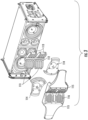
- FIG. 1 illustrates a perspective view of an acoustic assembly 100, which is in accordance with one or more embodiments of the present invention.
- the acoustic assembly 100 includes an enclosure 101.
- the enclosure 101 may include a modular construction, an integral construction, such as from a molding process, or a combination thereof.
- the enclosure 101 may include an exterior shape, which may appear cubic, rectangular, trapezoidal, spherical, conical, cylindrical, ellipsoidal, triangular, pentagonal, hexagonal, pyramidal, or another multi-sided three-dimensional shape.
- a cover 102 may removably attach to the enclosure 101.
- the cover 102 may be removably attached to the enclosure 101 by fasteners, adhesives, and/or other ways known in the art.
- the cover 102 may be shaped similarly or identical to one or more sides of the enclosure 101.
- the cover 102 may be a solid panel or an acoustically transparent grille. Using the solid panel as the cover 102 may be desirable for use during set-up, tear-down, transportation, and/or storage of the acoustic assembly 100.
- sensitive and/or critical components such as a loudspeaker diaphragm, that would otherwise be exposed to the surroundings may be completely covered and protected.
- the protection from the surroundings may be due to the solid panel's robust design, which is able to withstand forces commonly experienced with set-up, tear-down, transportation, and/or storage of the acoustic assembly 100. Under such forces, the solid panel will not fail. Conversely without the solid panel, such forces could impact the sensitive and/or critical components directly, which could cause those components to fail.
- using the acoustically transparent grille as the cover 102 may be desirable during operation of the acoustic assembly 100. During operation, the acoustically transparent grille does not interfere with sound waves produced from the acoustic assembly 100. As another alternative, the cover 102 may be removed completely before operating the acoustic assembly 100.
- the acoustic assembly 100 may be removably attached to one or more additional acoustic assemblies.
- one or more additional acoustic assemblies may be removably attached to the acoustic assembly 100 to create a line-array.
- the line-array may be hung, such as to a rafter or scaffolding, above a ground floor.
- the enclosure 101 of the acoustic assembly 100 is illustrated without the cover 102.
- the cover 102 may have been detached, such as by unscrewing threaded fasteners, from a first side 103 and a second side 104 of the enclosure 101. After detaching, the cover 102 may have been removed from the enclosure 101.
- the first side 103 may be laterally spaced from the second side 104 along an X axis.
- the first side 103 may generally be parallel to the second side 104, and the first side 103 may generally mirror the shape of the second side 104. Further on shape, the first side 103 and the second side 104 may include tapered portions, as shown in the illustrated embodiment. Additionally, the first side 103 and the second side 104 may attach to a top side 105, a bottom side 106, and a back side 107.
- the top side 105 may be laterally spaced from the bottom side 106 along a Y axis.
- the Y axis may be oriented 90degrees to the X axis.
- the back side 107 may attach to the top side 105 and the bottom side 106.
- the first side 103, the second side 104, the top side 105, the bottom side 106, and the back side 107 may define a cavity 108 for receiving at least one acoustic emitting device 109, such as a loudspeaker or a compression driver.
- the cavity may include a frame 110.
- the frame 110 may attach to the first side 103, the second side 104, the top side 105, the bottom side 106, and/or the back side 107.
- the frame 110 may be integrally formed with the first side 103, the second side 104, the top side 105, the bottom side 106, and/or the back side 107.
- the acoustic assembly 100 includes at least one acoustic horn 111.
- the at least one acoustic horn 111 at least partially covers the at least one acoustic emitting device 109.
- the at least one acoustic horn 111 may improve one or more acoustical parameters of the acoustic assembly.
- the at least one acoustic horn 111 may be designed to achieve a desired directivity of the acoustic assembly 100.
- the acoustic horn 111 may be designed to achieve a smooth, uninterrupted transition across frequency bands, which at least range from a low frequency (20Hz) to a high frequency (20KHz).
- the at least one acoustic horn 111 may attach to the first side 103, the second side 104, the top side 105, the bottom side 106, the back side 107, the at least one acoustic emitting device 109, and/or the frame 110.
- the attachments between the first side 103, the second side 104, the top side 105, the bottom side 106, the back side 107, the at least one acoustic emitting device 109, the frame 110, and/or the acoustic horn 111 may be serviceable or non-serviceable and may occur by fasteners, adhesive, and/or other ways known in the art.
- FIG. 3 illustrates an exploded view of the acoustic horn 111 for the acoustic assembly 100.
- the acoustic assembly 100 includes at least one waveguide 112, at least one lens 113, at least one plug 114, and/or at least one integrator 115.
- the at least one waveguide 112, the at least one lens 113, and the at least one plug 114 attach to the at least one integrator 115.
- the attachments may be permanent or non-permanent and may occur by fasteners, adhesive, and or/or other ways known in the art.
- a vibration absorbing layer (not shown) may be placed between the at least one integrator 115 and the at least one waveguide 112, the at least one lens 113, and/or the at least one plug 114.
- the at least one waveguide 112, the at least one lens 113, and/or the at least one plug 114 may be integrally formed with the at least one integrator 115.
- the at least one waveguide 112 may be positioned in front of an output opening of the at least one high-frequency compression driver. Positioning the at least one waveguide 112 in that manner allows the at least one waveguide 112 to receive and influence a sound wave-such as directivity-from the at least one high-frequency compression driver. In addition to positioning, the at least one waveguide 112 may attach to the at least one high-frequency compression driver.
- the at least one lens 113 may be positioned in front of an output side of the at least one mid-frequency loudspeaker. Positioning the at least one lens 113 in that manner allows the at least one lens 113 to receive and influence a sound wave-such as directivity-from the at least one mid-frequency loudspeaker. In addition to positioning, the at least one lens 113 may attach to the at least one mid-frequency loudspeaker.
- the at least one plug 114 may be positioned in front of an output side of the at least one low-frequency loudspeaker. Positioning the at least one plug 114 in that manner allows the at least one plug 114 to receive and influence a sound wave-such as directivity-from the at least one low-frequency loudspeaker.
- one or more of the at least one waveguide 112, the at least one lens 113, the at least one plug 114, and the at least one integrator 115 include at least one through-hole aperture 116, such as a slotted opening, for directing sound waves there-through.
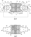
- FIG. 4 illustrates an example of the acoustic horn 111 for the acoustic assembly 100.
- the acoustic horn 111 aligns along an X' plane containing the X axis. Additionally, the acoustic horn 111 aligns along a Y' plane containing the Y axis. Like the X and Y axes, the X' plane is oriented 90degrees to the Y' plane.
- the acoustic horn 111 includes a center point 117 that is positioned along a line at the intersection of the X' plane and the Y' plane. The center point 117 may correspond to the intersection of the X axis and the Y axis.
- the acoustic horn 111 may include a desired directivity in the X' plane. Additionally, based on the design of the acoustic horn 111, the acoustic horn 111 may include a desired directivity in the Y' plane.
- the acoustic horn 111 includes a horizontal length H, which runs in the direction of the X axis. And along the Y' plane, the acoustic horn includes a vertical length V, which runs in the direction of the Y axis. The horizontal length H is greater than the vertical length V. Furthermore, the Y' plane may act as a first mirror such that a first portion of the acoustic horn 111 mirrors a second portion of the acoustic horn 111. Additionally, the X' plane may act as a second mirror such that a third portion of the acoustic horn 111 mirrors a fourth portion of the acoustic horn 111.
- the acoustic horn 111 includes one waveguide 112.
- the one waveguide 112 extends along the Y' plane.
- the one waveguide 112 may do so in the direction of the Y axis.
- the one waveguide 112 includes at least one through-hole aperture 116.
- the acoustic horn includes four lenses 113.
- the four lenses 113 may be evenly distributed around the X' plane and Y' plane. Additionally, the four lenses 113 may be adjacent to the one waveguide 112.
- Each of the four lenses 113 includes at least one through-hole aperture 116.
- the acoustic horn 111 includes two plugs 114.
- the two plugs 114 are laterally spaced from one another along the X' plane. The lateral spacing of the two plugs 114 may be done in the direction of the X axis.
- the acoustic horn 111 includes two integrators 115.
- the two integrators 115 may be adjacent to the one waveguide 112.
- Each of the two integrators 115 includes at least one through-hole aperture 116, which may be in fluid communication with one or more of the through-hole apertures 116 of the lenses 113.
- the one waveguide 112, the four lenses 113, and the two plugs 114 attach to the two integrators 115.
- the two plugs 114 and the two integrators 115 form two sealed chambers 118.
- the two sealed chambers 118 may be hollow or filled with a material.
- the two chambers 118 may act as resonators when used in the acoustic assembly 100.
- the two plugs 114 include overall horizontal lengths L along the X' plane, which run in the direction of the X axis. Additionally, the two plugs include overall vertical lengths D, which are in directions parallel to the Y axis on the Y' plane. The overall horizontal lengths L are greater than the vertical lengths D.
- the perimeters of the two plugs 114 are non-circular and include arcuate tapered segments 119. On the two plugs 114, with reference to the Y axis on the Y' plane, the arcuate tapered segments 119 begin at starting points 120 furthest from the X axis on the X' plane.
- the arcuate tapered segments 119 taper to end points 121 that are closer to the X axis on the X' plane than their respective starting points 120.
- radial segments 122 may complete the perimeters of the two plugs 114.
- the two integrators 115 include arcuate tapered segments 123 and radial segments 124, which correspond to the arcuate tapered segments 119 and the radial segments of the two plugs 114.
- the surfaces of the two plugs 114 may be smooth. Alternatively, the surfaces of the two plugs 114 may include one or more protrusions 125 and/or indentations 126.
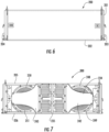
- FIGS. 6 through 11 illustrate an acoustic assembly 200, which is in accordance with one or more embodiments of the present invention.
- the acoustic assembly 200 includes an enclosure 201.
- a cover 202 removably attaches to the enclosure 201.
- the cover 202 removably attaches to a first side 203 and a second side 204 of the enclosure 201.
- the first side 203 and the second side 204 of the enclosure 201 attach to a top side 205, a bottom side 206, and a back side 207.
- the first side 203, the second side 204, the top side 205, the bottom side 206, and the back side 207 define a cavity 208 for receiving a first low-frequency loudspeaker 209, a second low-frequency loudspeaker 210, a first mid-frequency loudspeaker 211, a second mid-frequency loudspeaker 212, a third mid-frequency loudspeaker 213, a fourth mid-frequency loudspeaker 214, a first high-frequency compression driver 215, a second high-frequency compression driver 216, and a third high-frequency compression driver 217.
- the cavity includes a frame 218.
- the frame 218 at least attaches to the bottom side 206.
- the first and the second low-frequency loudspeakers 209, 210 are in the cavity 208 of the enclosure 201.
- the first and the second low-frequency loudspeakers 209, 210 are attached to the frame 218.
- the first and the second low-frequency loudspeakers 209, 210 align along a first plane 219.
- the first plane 219 bisects the first low-frequency loudspeaker 209.
- the first plane 219 bisects the second low-frequency loudspeaker 210.
- the first low-frequency loudspeaker 209 is laterally spaced from the second low-frequency loudspeaker 210.
- the first, the second, and the third high-frequency compression drivers 215, 216, 217 are aligned along a second plane 220.
- the first, the second, and the third high-frequency compression drivers 215, 216, 217 are attached to the frame 218.
- the second plane 220 is oriented 90degrees to the first plane 219.
- the second plane 220 bisects the first high-frequency compression driver 215, as well as the second high-frequency compression driver 216 and the third high-frequency compression driver 217.
- the second high-frequency compression driver 216 is also aligned along the first plane 219. Because of that, the first plane 219 also bisects the second compression driver 216.
- the first, the second, the third, and the fourth mid-frequency loudspeakers 211, 212, 213, 214 are distributed around the first plane 219 and the second plane 220. Because the first plane 219 and the second plane 220 intersect, the first plane 219 and the second plane 220 form four quadrants: I, II, III, and IV.
- quadrant I the first mid-frequency loudspeaker 211 is positioned and attached to the frame 218.
- the third mid-frequency loudspeaker 213 is positioned and attached to the frame 218.
- the fourth mid-frequency loudspeaker 214 is positioned and attached to the frame 218.
- the second mid-frequency loudspeaker 212 is positioned and attached to the frame 218.
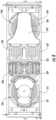
- the first low-frequency loudspeaker 209 includes a rear face 221 that faces the back side 207. Additionally, the second low-frequency loudspeaker 210 includes a rear face 222 that also faces the back side 207. Opposite the rear face 221, the first low-frequency loudspeaker 209 includes a front output side 223. The front output side 223 of the first low-frequency loudspeaker 209 is at least defined by a diaphragm 224. When the cover 202 is attached, the front output side 223 faces the cover 202. Additionally, opposite the rear face 222, the second low-frequency loudspeaker 210 includes a front output side 225.
- the front output side 225 of the second low-frequency loudspeaker 210 is at least defined by a diaphragm 226. Like the first low-frequency loudspeaker 209, the front output side 225 of the second low-frequency loudspeaker 210 also faces the cover 202, when the cover 202 is attached.
- the first, the second, and the third high-frequency compression drivers 215, 216, 217 include a first output opening 227, a second output opening 228, and a third output opening 229, respectively.
- the first output opening 227, the second output opening 228, and the third output opening 229 face the cover 202.
- the first, the second, the third, and the fourth mid-frequency loudspeakers 211, 212, 213, 214 include front output sides 230, 231, 232, 233, respectively.
- the front output sides 230, 231, 232, 233 of the four mid-frequency loudspeakers 211, 212, 213, 214 generally face the cover 202.
- the front output sides 230, 231, 232, 233 of the four mid-frequency loudspeakers are angled toward the second plane 220.
- the acoustic assembly 200 includes an acoustic horn 234.
- the acoustic horn includes a waveguide 235.
- the waveguide 235 is aligned along the second plane 220.
- the second plane 220 bisects the waveguide 235.
- the waveguide 235 is positioned in front of the first output opening 227, the second output opening 228, and the third output opening 229 of the first, the second, and the third high-frequency compression drivers 215, 216, 217. Because of the positioning, the waveguide 235 receives and influences sound waves from the first, the second, and the third high-frequency compression drivers 215, 216, 217.
- the cover 202 is attached, the waveguide 235 is between the cover 202 and the first, the second, and the third high-frequency compression drivers 215, 216, 217.
- the acoustic horn 234 includes a first lens 236, a second lens 237, a third lens 238, and a fourth lens 239.
- the first lens 236 is positioned in front of the front output side 230.
- the second lens 237 is positioned in front of the front output side 231.
- the third lens 238 is positioned in front of the front output side 232.
- the fourth lens 239 is positioned in front of the front output side 233.
- the first, the second, the third, and the fourth lenses 236, 237, 238, 239 receive and influence sound waves from the first, the second, the third, and the fourth mid-frequency loudspeakers 211, 212, 213, 214.
- the first, the second, the third, and the fourth lenses 236, 237, 238, 239 are positioned between the cover 202 and the first, the second, the third, and the fourth mid-frequency loudspeakers 211, 212, 213, 214.
- the acoustic horn 234 includes a first plug 240 and a second plug 241.
- the first plug 240 is positioned in front of the front output side 223.
- the second plug 241 is positioned in front of the front output side 225. Because of the positioning, the first and the second plugs 240, 241 receive and influence sound waves from the first and the second low-frequency loudspeakers 209, 210.
- the cover 202 is attached, the first and the second plugs 240, 241 are positioned between the cover 202 and the first and the second low-frequency loudspeakers 209, 210.
- the acoustic horn 234 includes a first integrator 242 and a second integrator 243.
- the waveguide 235, the first lens 236, the second lens 237, and the first plug 240 are attached to the first integrator 242.
- the waveguide 235, the third lens 238, and the fourth lens 239, and the second plug 241 are attached to the second integrator 243.
- the first integrator 242 at least covers the first mid-frequency loudspeaker 211, the second mid-frequency loudspeaker 212, and the first plug 240.
- the second integrator 243 at least covers the third mid-frequency loudspeaker 213, the fourth mid-frequency loudspeaker 214, and the second plug 241.
- the cover 202 covers the first integrator 242 and the second integrator 243.
- the first plug 240 may have a convex side 244, and the second plug 241 may have a convex side 245.
- the convex side 244 may face the diaphragm 224 of the first low-frequency loudspeaker 209.
- the diaphragm 224 may have a conical shape, which may be a frustoconical shape.
- the first low-frequency loudspeaker 209 may have a cone volume 246 defined by the diaphragm 224.
- the convex side 244 of the first plug 240 may be positioned into a portion of the cone volume 246. During operation of the first low-frequency loudspeaker 209, the diaphragm 224, however, does not contact the first plug 240.
- the convex side 244 of the first plug is spaced from the diaphragm 224 of the first low-frequency loudspeaker 209, such that the diaphragm 224 does not contact the first plug 240 during operation of the first low-frequency loudspeaker 209. Furthermore, during operation, sound waves from the first low-frequency loudspeaker 209 may travel around the first plug 240.
- the convex side 245 may face the diaphragm 226 of the second low-frequency loudspeaker 210.
- the diaphragm 226 may have a conical shape, which may be a frustoconical shape.
- the second low-frequency loudspeaker 210 may have a cone volume 247 defined by the diaphragm 226.
- the cone volume 247 of the second low-frequency loudspeaker 210 may equal the cone volume 246 of the first low-frequency loudspeaker 209.
- the convex side 245 of the second plug 241 may be positioned into a portion of the cone volume 247 of the second low-frequency loudspeaker 210.
- the diaphragm 226 does not contact the second plug 241, because the convex side 245 is spaced from the diaphragm 226. Furthermore, during operation, sound waves from the second low-frequency loudspeaker 210 may travel around the second plug 241.
- the first low-frequency loudspeaker when the first integrator 242 and the first plug 240 are positioned in front of the first low-frequency loudspeaker 209, the first low-frequency loudspeaker includes a first unobstructed area 248 and a second unobstructed area 249. This is because the first integrator 242 and the first plug 240 only cover a portion of the front output side 223 of the first low-frequency loudspeaker 209.
- the second low-frequency loudspeaker 210 when the second integrator 243 and the second plug 241 are positioned in front of the second low-frequency loudspeaker 210, the second low-frequency loudspeaker 210 includes a first unobstructed area 250 and a second unobstructed area 251. This is also because the second integrator 243 and the second plug 241 only cover a portion of the front output side 225 of the second low-frequency loudspeaker 210.
- the acoustic assembly 200 may include a first crossover region and a second crossover region.
- the first crossover region may be the overlap in frequency ranges between the low-frequency loudspeakers 209, 210 and at least the mid-frequency loudspeakers 211, 212, 213, 214.
- the second crossover region may be the overlap in frequency ranges between the high-frequency compression drivers 215, 216, 217 and at least the mid-frequency loudspeakers 211,212,213,214.
- the low-frequency loudspeakers 209, 210 may include sound coverage patterns that may be identical to at least the mid-frequency loudspeakers' 211, 212, 213, 214 sound coverage patterns.
- the first and the second low-frequency loudspeakers 209, 210 may include a first sound coverage angle in the first plane 219 and a second sound coverage angle in the second plane 220.
- at least the first, the second, the third, and the fourth mid-frequency loudspeakers 211, 212, 213, 214 may include a third sound coverage angle in the first plane 219 and a fourth sound coverage angle in the second plane 220.
- the first sound coverage angle may be equal to the third sound coverage angle
- the second sound coverage angle may be equal to the fourth sound coverage angle. This may be achieved by the acoustic horn 234 in the acoustic assembly 200.
- the high-frequency compression drivers 215, 216, 217 may include sound coverage patterns that may be identical to at least the mid-frequency loudspeakers' 211, 212, 213, 214 sound coverage patterns.
- the high-frequency compression drivers 215, 216, 217 may include a first sound coverage angle in the first plane 219 and a second sound coverage angle in the second plane 220.
- at least the first, the second, the third, and the fourth mid-frequency loudspeakers 211, 212, 213, 214 may include a third sound coverage angle in the first plane 219 and a fourth sound coverage angle in the second plane 220.
- the first sound coverage angle may be equal to the third sound coverage angle
- the second sound coverage angle may be equal to the fourth sound coverage angle. This may be achieved by the acoustic horn 234 in the acoustic assembly 200.
- the acoustic assembly 200 may include a third crossover region.
- the third crossover region may be the overlap in frequency ranges between the low-frequency loudspeakers 209, 210 and the high-frequency compression drivers 215, 216, 217.
- the low-frequency loudspeakers 209, 210 may include sound coverage patterns that may be identical to the high-frequency compression drivers 215, 216, 217.
- the low-frequency loudspeakers 209, 210 may include a first sound coverage angle in the first plane 219 and a second sound coverage angle in the second plane 220.
- the high-frequency compression drivers 215, 216, 217 include a third sound coverage angle in the first plane 219 and a fourth sound coverage angle in the second plane 220.
- the first sound coverage angle may be equal to the third sound coverage angle
- the second sound coverage angle may be equal to the fourth sound coverage angle. This may be achieved by the acoustic horn 234 in the acoustic assembly 200.
- the acoustic horn 234 in the acoustic assembly 200 may result in a uniform coverage pattern over a listening area in the first plane 219 and/or the second plane 220.
- the uniform coverage pattern may result in an improved listening experience for persons located in the listening area. That is because the coverage pattern may not differ at various locations inside of the listening area.
- embodiments herein may improve directivity for acoustic assemblies that include at least one acoustic emitting device and operate over the audible hearing range (20Hz to 20KHz).
- FIG. 12 illustrates a virtual-simulation 300 of an acoustic assembly according to one or more embodiments.
- the virtual-simulation 300 illustrates ideal horiztonal beamwidths for the acoustic assembly (i.e., sound coverage angle in a horizontal plane versus frequency).
- the virtual-simulation 300 illustrates a horizontal beamwidth 301 for at least one low-frequency acoustic emitting device, a horizontal beamwidth 302 for at least one mid-frequency acoustic emitting device, and a horizontal beamwidth 303 for at least one high-frequency acoustic emitting device.
- the virtual-simulation 300 further illustrates a first crossover region 304 between the at least one low-frequency acoustic emitting device and the at least one mid-frequency acoustic emitting device. Further, the virtual-simulation illustrates a second crossover region 305 between the at least one mid-frequency acoustic emitting device and the at least one high-frequency acoustic emitting device.
- the first crossover region 304 extends from around 200Hz to around 600Hz
- the second crossover region 305 extends from around 600Hz to 2,000Hz.
- the at least one low-frequency acoustic emitting device decreases in sound coverage angle as frequency increases. That decrease may be linear. Thus, the decrease in sound coverage angle as frequency increases for the at least one low-frequency acoustic emitting device in the first crossover region 304 may have a constant slope. Similarly, in the first crossover region 304, the at least one mid-frequency acoustic emitting device decreases in sound coverage angle as frequency increases. That decrease may similarly be linear. Thus, the decrease in sound coverage angle as frequency increases for the at least one mid-frequency acoustic emitting device in the first crossover region 304 may have a constant slope.
- the slope of decrease for the at least one low-frequency acoustic emitting device may be equal to the slope of decrease for the at least one mid-frequency acoustic emitting device.
- the curve of decrease for the at least one low-frequency acoustic emitting device may be parallel to the curve of decrease for the at least one mid-frequency acoustic emitting device.
- the equal slope and/or parallel curves may be a byproduct of the acoustic horn in the acoustic assembly.
- the sound coverage angle for the at least one mid-frequency acoustic emitting device may be greater than the sound coverage angle for the at least one low-frequency acoustic emitting device at a given frequency.
- the net result may yield a constant coverage angle.
- the net result yields or substantially yields a sound coverage angle of 100degrees.
- the net result may be a byproduct of the acoustic horn in the acoustic assembly. This may be due to the interaction between the at least one low-frequency acoustic emitting device, the at least one mid-frequency acoustic emitting device, and the acoustic horn in the acoustic assembly.
- the at least one mid-frequency acoustic emitting device decreases in sound coverage angle as frequency increases. That decrease may be linear. Thus, the decrease in sound coverage angle as frequency increases for the at least one mid-frequency acoustic emitting device in the second crossover region 305 may have a constant slope.
- the at least one high-frequency acoustic emitting device decreases in sound coverage angle as frequency increases. That decrease may similarly be linear. Thus, the decrease in sound coverage angle as frequency increases for the at least one high-frequency acoustic emitting device in the second crossover region 305 may have a constant slope.
- the slope of decrease for the at least one mid-frequency acoustic emitting device may be equal to the slope of decrease for the at least one high-frequency acoustic emitting device.
- the curve of decrease for the at least one mid-frequency acoustic emitting device may be parallel or substantially parallel to the curve of decrease for the at least one high-frequency acoustic emitting device.
- the sound coverage angle for the at least one mid-frequency acoustic emitting device may be less than the sound coverage angle for the at least one high-frequency acoustic emitting device at a given frequency.
- the net result may yield a constant coverage angle.
- the net result yields or substantially yields a sound coverage angle of 100degrees.
- the net result may be a byproduct of the acoustic horn in the acoustic assembly. This may be due to the interaction between the at least one mid-frequency acoustic emitting device, the at least one high-frequency acoustic emitting device, and the acoustic horn in the acoustic assembly.
- the acoustic horn in the acoustic assembly improves the beamwidths in a given plane, such as the horizontal plane or vertical plane. This improvement may be particularly evident in the crossover regions of the acoustic assembly. In the crossover regions, the acoustic horn may achieve desirable beamwidths.
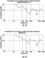
- FIG. 13 illustrates results of a mid-frequency test of a modified acoustic assembly 400, which is primarily based on the acoustic assembly 200 of FIGS. 6-11 .
- the modified acoustic assembly 400 does not include a first plug or a second plug, nor does the modified acoustic assembly 400 include a first integrator that extends over a first low-frequency loudspeaker or a second integrator that extends over a second low-frequency loudspeaker. Instead, the first and the second integrators in the modified acoustic assembly 400 stop short of the first and the second low-frequency loudspeakers.
- the modified acoustic assembly is based on the acoustic assembly 200 of FIGS. 6-11 .
- the mid-frequency test of the modified acoustic assembly 400 illustrates a horizontal beamwidth 401.
- FIG. 14 illustrates results of a mid-frequency test of an acoustic assembly 500, which is based on the acoustic assembly 200 of FIGS. 6-11 .
- the acoustic assembly 500 does include a first plug and a second plug, which are positioned in front of a first and a second low-frequency loudspeaker, like in the acoustic assembly 200.
- the acoustic assembly 500 includes a first integrator and a second integrator that does extend over portions of the first and the second low-frequency loudspeakers, like in the acoustic assembly 200.
- the modified acoustic assembly 400 and the acoustic assembly 500 are identical.
- the mid-frequency test of the acoustic assembly 500 illustrates a horizontal beamwidth 501.
- the acoustic assembly 500 outperforms the modified acoustic assembly 400 because the horizontal beamwidth 501 of the acoustic assembly 500 includes a nearly linear decrease in sound coverage angle over frequency between around 100Hz to around 2,000Hz. Conversely, the modified acoustic assembly 400 yields a significantly non-linear curve over that range. The nearly linear decrease for the horizontal beamwidth 501 of the acoustic assembly 500 is preferable than the significantly non-linear curve for the horizontal beamwidth of the modified acoustic assembly 400.
- the nearly linear decrease for the horizontal beamwidth 501 of the acoustic assembly 500 is closer to the corresponding ideal beamwidth 302 that is depicted in the virtual-simulation 300 than the significantly non-linear curve for the horizontal beamwidth 401 of the modified acoustic assembly 400.
Landscapes
- Health & Medical Sciences (AREA)
- Otolaryngology (AREA)
- Physics & Mathematics (AREA)
- Engineering & Computer Science (AREA)
- Acoustics & Sound (AREA)
- Signal Processing (AREA)
- Multimedia (AREA)
- Circuit For Audible Band Transducer (AREA)
- Obtaining Desirable Characteristics In Audible-Bandwidth Transducers (AREA)
Claims (5)
- Akustische Anordnung (100; 200), umfassend:ein Gehäuse (101; 201);einen ersten Wandler, der an dem Gehäuse (101; 201) befestigt und dazu konfiguriert ist, Geräusche entlang eines ersten Pfades über einen ersten Frequenzbereich zu emittieren;einen zweiten Wandler, der an dem Gehäuse (101; 201) befestigt und dazu konfiguriert ist, Geräusche entlang eines zweiten Pfades über einen zweiten Frequenzbereich zu emittieren;einen dritten Wandler, der an dem Gehäuse (101; 201) befestigt und dazu konfiguriert ist, Geräusche entlang eines dritten Pfades über einen dritten Frequenzbereich zu emittieren; undeinen Schalltrichter (111; 234), der an dem Gehäuse (101; 201) befestigt und so positioniert ist, dass er sich mindestens teilweise in den ersten Pfad und den zweiten Pfad erstreckt, um mindestens eine Strahlbreite in einem Crossover-Bereich des ersten Frequenzbereichs und des zweiten Frequenzbereichs einzustellen, wobei der Schalltrichter (111; 234) so positioniert ist, dass er sich mindestens teilweise in den dritten Pfad erstreckt, um mindestens eine Strahlbreite in einem Crossover-Bereich des zweiten Frequenzbereichs und des dritten Frequenzbereichs einzustellen, wobei der Schalltrichter (111; 234) Folgendes beinhaltet:einen Wellenleiter (112; 235), der so positioniert ist, dass er sich mindestens teilweise in den ersten Pfad erstreckt, wobei der Wellenleiter (112; 235) mindestens eine erste Durchgangslochöffnung (116) beinhaltet; undzwei Integratoren (115; 242, 243), die an dem Wellenleiter (112; 235) befestigt und so positioniert sind, dass sie sich mindestens teilweise in den zweiten Pfad und den dritten Pfad erstrecken, wobei jeder der zwei Integratoren (115; 242, 243) mindestens eine zweite Durchgangslochöffnung (116) zum Leiten von Geräuschwellen hindurch beinhaltet,wobei der Schalltrichter (111; 234) ferner vier Linsen (113; 236, 237, 238, 239) umfasst, die so positioniert sind, dass sie sich mindestens teilweise in den zweiten Pfad erstrecken, und zwei Stecker (114; 240, 241), die so positioniert sind, dass sie sich mindestens teilweise in den dritten Pfad erstrecken, wobei die Linsen (113; 236, 237, 238, 239) und die Stecker (114; 240, 241) an dem Integrator (115; 242, 243) befestigt sind, wobei jede der vier Linsen (113; 236, 237, 238, 239) mindestens eine dritte Durchgangslochöffnung (116) beinhaltet, wobei die zwei Stecker (114, 240, 241) entlang einer ersten Ebene (219) seitlich voneinander beabstandet sind, wobei der Schalltrichter (234) entlang der ersten Ebene (219) ausgerichtet ist und wobei die zwei Stecker (114; 240, 241) und die zwei Integratoren (115; 242, 243) zwei abgedichtete Kammern (118) bilden.
- Akustische Anordnung (200) nach Anspruch 1, wobei die zwei Integratoren einen ersten Integrator (242) und einen zweiten Integrator (243) umfassen undwobei der Schalltrichter (234) entlang der ersten Ebene (219), die das Gehäuse (201) halbiert, und einer zweiten Ebene (220), die senkrecht zu der ersten Ebene (219) angeordnet ist, ausgerichtet ist, und wobei der Wellenleiter (235) entlang der zweiten Ebene (220) ausgerichtet ist;der erste Integrator (242) entlang der ersten Ebene (219) ausgerichtet ist; undder zweite Integrator (243) entlang des ersten Integrators (242) auf der ersten Ebene (219) ausgerichtet und von diesem beabstandet ist.
- Akustische Anordnung (200) nach Anspruch 2, wobei die zweite Ebene (220) einen ersten Abschnitt des Schalltrichters (234) von einem zweiten Abschnitt des Schalltrichters (234) gleichmäßig halbiert, wobei der erste Abschnitt den zweiten Abschnitt spiegelt.
- Akustische Anordnung (200) nach Anspruch 1, ferner umfassend:eine erste Vielzahl von Wandlern (215, 216, 217), einschließlich des ersten Wandlers, die an dem Gehäuse (201) befestigt ist und dazu konfiguriert ist, Geräusche über den ersten Frequenzbereich zu emittieren;eine zweite Vielzahl von Wandlern (211, 212, 213, 214), einschließlich des zweiten Wandlers, die an dem Gehäuse (201) befestigt ist und dazu konfiguriert ist, Geräusche über den zweiten Frequenzbereich zu emittieren;eine dritte Vielzahl von Wandlern (209, 210), einschließlich des dritten Wandlers, die an dem Gehäuse (201) befestigt ist und dazu konfiguriert ist, Geräusche über den dritten Frequenzbereich zu emittieren; undwobei die zwei Integratoren einen ersten Integrator (242) und einen zweiten Integrator (243) umfassen und wobeider erste Integrator (242) an dem Wellenleiter (235) befestigt ist; undder zweite Integrator (243) an dem Wellenleiter (235) befestigt und von dem ersten Integrator (242) beabstandet ist.
- Akustische Anordnung (200) nach Anspruch 4, wobei der Schalltrichter (234) entlang einer ersten Ebene und einer zweiten Ebene, die senkrecht zur der ersten Ebene ist, ausgerichtet ist, wobei der Wellenleiter (235) entlang der zweiten Ebene ausgerichtet ist und der erste Integrator (242) und der zweite Integrator (243) entlang der ersten Ebene ausgerichtet sind.
Applications Claiming Priority (2)
| Application Number | Priority Date | Filing Date | Title |
|---|---|---|---|
| US201662440872P | 2016-12-30 | 2016-12-30 | |
| PCT/US2017/068936 WO2018126122A1 (en) | 2016-12-30 | 2017-12-29 | Acoustic horn for an acoustic assembly |
Publications (3)
| Publication Number | Publication Date |
|---|---|
| EP3563589A1 EP3563589A1 (de) | 2019-11-06 |
| EP3563589A4 EP3563589A4 (de) | 2020-08-26 |
| EP3563589B1 true EP3563589B1 (de) | 2024-10-23 |
Family
ID=62710926
Family Applications (1)
| Application Number | Title | Priority Date | Filing Date |
|---|---|---|---|
| EP17889438.2A Active EP3563589B1 (de) | 2016-12-30 | 2017-12-29 | Akustische hupe für eine akustische anordnung |
Country Status (4)
| Country | Link |
|---|---|
| US (1) | US11044551B2 (de) |
| EP (1) | EP3563589B1 (de) |
| CN (1) | CN110115047B (de) |
| WO (1) | WO2018126122A1 (de) |
Families Citing this family (3)
| Publication number | Priority date | Publication date | Assignee | Title |
|---|---|---|---|---|
| EP4165625B1 (de) * | 2020-06-10 | 2024-08-28 | Dolby Laboratories Licensing Corporation | Asymmetrischer schalltrichter |
| USD1032558S1 (en) * | 2021-10-22 | 2024-06-25 | Harman International Industries, Incorporated | Loudspeaker |
| US12407980B2 (en) | 2023-03-01 | 2025-09-02 | Qsc, Llc | Customizable waveguides and associated systems and methods |
Family Cites Families (12)
| Publication number | Priority date | Publication date | Assignee | Title |
|---|---|---|---|---|
| US6081602A (en) * | 1997-08-19 | 2000-06-27 | Meyer Sound Laboratories Incorporated | Arrayable two-way loudspeaker system and method |
| US6343133B1 (en) | 1999-07-22 | 2002-01-29 | Alan Brock Adamson | Axially propagating mid and high frequency loudspeaker systems |
| US7027605B2 (en) | 1999-10-20 | 2006-04-11 | Harman International Industries, Incorporated | Mid-range loudspeaker |
| US6513622B1 (en) * | 1999-11-02 | 2003-02-04 | Harman International Industries, Incorporated | Full-range loudspeaker system for cinema screen |
| US7324654B2 (en) | 2000-07-31 | 2008-01-29 | Harman International Industries, Inc. | Arbitrary coverage angle sound integrator |
| TWI247550B (en) | 2002-03-05 | 2006-01-11 | Audio Products Int Corp | Loudspeaker, loudspeaker system and method of directing sound waves from a driver of a loudspeaker |
| US7278513B2 (en) | 2002-04-05 | 2007-10-09 | Harman International Industries, Incorporated | Internal lens system for loudspeaker waveguides |
| FR2875367B1 (fr) * | 2004-09-13 | 2006-12-15 | Acoustics Sa L | Systeme de sonorisation directivite reglable |
| BRPI0917410A2 (pt) * | 2008-08-14 | 2015-12-01 | Harman Int Ind | tampão de fase e lente acústica para alto-falante de radiação direta |
| US8804982B2 (en) | 2011-04-02 | 2014-08-12 | Harman International Industries, Inc. | Dual cell MEMS assembly |
| US9571923B2 (en) * | 2015-01-19 | 2017-02-14 | Harman International Industries, Incorporated | Acoustic waveguide |
| WO2016168513A1 (en) * | 2015-04-14 | 2016-10-20 | Meyer Sound Laboratories Incorporated | Arrayable loudspeaker with constant wide beamwidth |
-
2017
- 2017-12-29 EP EP17889438.2A patent/EP3563589B1/de active Active
- 2017-12-29 US US16/474,984 patent/US11044551B2/en active Active
- 2017-12-29 CN CN201780080984.0A patent/CN110115047B/zh active Active
- 2017-12-29 WO PCT/US2017/068936 patent/WO2018126122A1/en not_active Ceased
Also Published As
| Publication number | Publication date |
|---|---|
| EP3563589A1 (de) | 2019-11-06 |
| CN110115047A (zh) | 2019-08-09 |
| EP3563589A4 (de) | 2020-08-26 |
| CN110115047B (zh) | 2021-01-12 |
| US11044551B2 (en) | 2021-06-22 |
| US20190349672A1 (en) | 2019-11-14 |
| WO2018126122A1 (en) | 2018-07-05 |
Similar Documents
| Publication | Publication Date | Title |
|---|---|---|
| JP5662462B2 (ja) | 無指向性スピーカ | |
| EP3501184B1 (de) | Kompressionstreiber und phase-plug-anordnung dafür | |
| EP3646616B1 (de) | Elektroakustischer wandler eines soundsystems | |
| EP2321976B1 (de) | Vernestete zusammengesetzte lautsprecherantriebseinheit | |
| US20120121118A1 (en) | Slotted waveguide for loudspeakers | |
| EP3563589B1 (de) | Akustische hupe für eine akustische anordnung | |
| CN104780487A (zh) | 用于声换能器的带凹槽且细长的孔眼 | |
| US12363474B2 (en) | Omnidirectional loudspeaker with asymmetric vertical directivity | |
| US7577265B2 (en) | Loudspeaker system providing improved sound presence and frequency response in mid and high frequency ranges | |
| US20100014697A1 (en) | Shaped Loudspeaker | |
| CN107980224B (zh) | 全向扬声器系统及相关设备和方法 | |
| KR100312000B1 (ko) | 스피커 | |
| US10341761B2 (en) | Acoustic waveguide for audio speaker | |
| JP2018201175A (ja) | スピーカー | |
| JP3931132B2 (ja) | スピーカ装置 | |
| JP3219058B2 (ja) | スピーカ | |
| KR20260009892A (ko) | 라우드스피커 구동 유닛 | |
| HK1171892A (zh) | 全向扬声器 | |
| JP2020178147A (ja) | 天井埋込型スピーカー |
Legal Events
| Date | Code | Title | Description |
|---|---|---|---|
| STAA | Information on the status of an ep patent application or granted ep patent |
Free format text: STATUS: THE INTERNATIONAL PUBLICATION HAS BEEN MADE |
|
| PUAI | Public reference made under article 153(3) epc to a published international application that has entered the european phase |
Free format text: ORIGINAL CODE: 0009012 |
|
| STAA | Information on the status of an ep patent application or granted ep patent |
Free format text: STATUS: REQUEST FOR EXAMINATION WAS MADE |
|
| 17P | Request for examination filed |
Effective date: 20190612 |
|
| AK | Designated contracting states |
Kind code of ref document: A1 Designated state(s): AL AT BE BG CH CY CZ DE DK EE ES FI FR GB GR HR HU IE IS IT LI LT LU LV MC MK MT NL NO PL PT RO RS SE SI SK SM TR |
|
| AX | Request for extension of the european patent |
Extension state: BA ME |
|
| DAV | Request for validation of the european patent (deleted) | ||
| DAX | Request for extension of the european patent (deleted) | ||
| A4 | Supplementary search report drawn up and despatched |
Effective date: 20200723 |
|
| RIC1 | Information provided on ipc code assigned before grant |
Ipc: H04R 1/02 20060101ALN20200718BHEP Ipc: H04R 1/24 20060101AFI20200718BHEP Ipc: H04R 27/00 20060101ALI20200718BHEP Ipc: H04R 1/26 20060101ALI20200718BHEP Ipc: H04R 1/34 20060101ALI20200718BHEP Ipc: H04R 1/28 20060101ALN20200718BHEP Ipc: H04R 1/40 20060101ALN20200718BHEP |
|
| STAA | Information on the status of an ep patent application or granted ep patent |
Free format text: STATUS: EXAMINATION IS IN PROGRESS |
|
| 17Q | First examination report despatched |
Effective date: 20220203 |
|
| REG | Reference to a national code |
Ref country code: DE Ref legal event code: R079 Free format text: PREVIOUS MAIN CLASS: H04R0001260000 Ipc: H04R0001240000 Ref country code: DE Ref legal event code: R079 Ref document number: 602017085709 Country of ref document: DE Free format text: PREVIOUS MAIN CLASS: H04R0001260000 Ipc: H04R0001240000 |
|
| GRAP | Despatch of communication of intention to grant a patent |
Free format text: ORIGINAL CODE: EPIDOSNIGR1 |
|
| STAA | Information on the status of an ep patent application or granted ep patent |
Free format text: STATUS: GRANT OF PATENT IS INTENDED |
|
| INTG | Intention to grant announced |
Effective date: 20240621 |
|
| RIC1 | Information provided on ipc code assigned before grant |
Ipc: H04R 1/40 20060101ALN20240610BHEP Ipc: H04R 1/02 20060101ALN20240610BHEP Ipc: H04R 1/28 20060101ALN20240610BHEP Ipc: H04R 27/00 20060101ALI20240610BHEP Ipc: H04R 1/34 20060101ALI20240610BHEP Ipc: H04R 1/26 20060101ALI20240610BHEP Ipc: H04R 1/24 20060101AFI20240610BHEP |
|
| GRAS | Grant fee paid |
Free format text: ORIGINAL CODE: EPIDOSNIGR3 |
|
| GRAA | (expected) grant |
Free format text: ORIGINAL CODE: 0009210 |
|
| STAA | Information on the status of an ep patent application or granted ep patent |
Free format text: STATUS: THE PATENT HAS BEEN GRANTED |
|
| AK | Designated contracting states |
Kind code of ref document: B1 Designated state(s): AL AT BE BG CH CY CZ DE DK EE ES FI FR GB GR HR HU IE IS IT LI LT LU LV MC MK MT NL NO PL PT RO RS SE SI SK SM TR |
|
| REG | Reference to a national code |
Ref country code: GB Ref legal event code: FG4D |
|
| REG | Reference to a national code |
Ref country code: CH Ref legal event code: EP |
|
| P01 | Opt-out of the competence of the unified patent court (upc) registered |
Free format text: CASE NUMBER: APP_52518/2024 Effective date: 20240919 |
|
| REG | Reference to a national code |
Ref country code: DE Ref legal event code: R096 Ref document number: 602017085709 Country of ref document: DE |
|
| REG | Reference to a national code |
Ref country code: IE Ref legal event code: FG4D |
|
| REG | Reference to a national code |
Ref country code: LT Ref legal event code: MG9D |
|
| REG | Reference to a national code |
Ref country code: NL Ref legal event code: MP Effective date: 20241023 |
|
| REG | Reference to a national code |
Ref country code: AT Ref legal event code: MK05 Ref document number: 1735826 Country of ref document: AT Kind code of ref document: T Effective date: 20241023 |
|
| PG25 | Lapsed in a contracting state [announced via postgrant information from national office to epo] |
Ref country code: NL Free format text: LAPSE BECAUSE OF FAILURE TO SUBMIT A TRANSLATION OF THE DESCRIPTION OR TO PAY THE FEE WITHIN THE PRESCRIBED TIME-LIMIT Effective date: 20241023 |
|
| PG25 | Lapsed in a contracting state [announced via postgrant information from national office to epo] |
Ref country code: NL Free format text: LAPSE BECAUSE OF FAILURE TO SUBMIT A TRANSLATION OF THE DESCRIPTION OR TO PAY THE FEE WITHIN THE PRESCRIBED TIME-LIMIT Effective date: 20241023 |
|
| PG25 | Lapsed in a contracting state [announced via postgrant information from national office to epo] |
Ref country code: IS Free format text: LAPSE BECAUSE OF FAILURE TO SUBMIT A TRANSLATION OF THE DESCRIPTION OR TO PAY THE FEE WITHIN THE PRESCRIBED TIME-LIMIT Effective date: 20250223 Ref country code: HR Free format text: LAPSE BECAUSE OF FAILURE TO SUBMIT A TRANSLATION OF THE DESCRIPTION OR TO PAY THE FEE WITHIN THE PRESCRIBED TIME-LIMIT Effective date: 20241023 Ref country code: PT Free format text: LAPSE BECAUSE OF FAILURE TO SUBMIT A TRANSLATION OF THE DESCRIPTION OR TO PAY THE FEE WITHIN THE PRESCRIBED TIME-LIMIT Effective date: 20250224 |
|
| PG25 | Lapsed in a contracting state [announced via postgrant information from national office to epo] |
Ref country code: FI Free format text: LAPSE BECAUSE OF FAILURE TO SUBMIT A TRANSLATION OF THE DESCRIPTION OR TO PAY THE FEE WITHIN THE PRESCRIBED TIME-LIMIT Effective date: 20241023 |
|
| PG25 | Lapsed in a contracting state [announced via postgrant information from national office to epo] |
Ref country code: BG Free format text: LAPSE BECAUSE OF FAILURE TO SUBMIT A TRANSLATION OF THE DESCRIPTION OR TO PAY THE FEE WITHIN THE PRESCRIBED TIME-LIMIT Effective date: 20241023 |
|
| PG25 | Lapsed in a contracting state [announced via postgrant information from national office to epo] |
Ref country code: ES Free format text: LAPSE BECAUSE OF FAILURE TO SUBMIT A TRANSLATION OF THE DESCRIPTION OR TO PAY THE FEE WITHIN THE PRESCRIBED TIME-LIMIT Effective date: 20241023 |
|
| PG25 | Lapsed in a contracting state [announced via postgrant information from national office to epo] |
Ref country code: NO Free format text: LAPSE BECAUSE OF FAILURE TO SUBMIT A TRANSLATION OF THE DESCRIPTION OR TO PAY THE FEE WITHIN THE PRESCRIBED TIME-LIMIT Effective date: 20250123 |
|
| PG25 | Lapsed in a contracting state [announced via postgrant information from national office to epo] |
Ref country code: LV Free format text: LAPSE BECAUSE OF FAILURE TO SUBMIT A TRANSLATION OF THE DESCRIPTION OR TO PAY THE FEE WITHIN THE PRESCRIBED TIME-LIMIT Effective date: 20241023 Ref country code: GR Free format text: LAPSE BECAUSE OF FAILURE TO SUBMIT A TRANSLATION OF THE DESCRIPTION OR TO PAY THE FEE WITHIN THE PRESCRIBED TIME-LIMIT Effective date: 20250124 Ref country code: AT Free format text: LAPSE BECAUSE OF FAILURE TO SUBMIT A TRANSLATION OF THE DESCRIPTION OR TO PAY THE FEE WITHIN THE PRESCRIBED TIME-LIMIT Effective date: 20241023 |
|
| PG25 | Lapsed in a contracting state [announced via postgrant information from national office to epo] |
Ref country code: PL Free format text: LAPSE BECAUSE OF FAILURE TO SUBMIT A TRANSLATION OF THE DESCRIPTION OR TO PAY THE FEE WITHIN THE PRESCRIBED TIME-LIMIT Effective date: 20241023 |
|
| PG25 | Lapsed in a contracting state [announced via postgrant information from national office to epo] |
Ref country code: RS Free format text: LAPSE BECAUSE OF FAILURE TO SUBMIT A TRANSLATION OF THE DESCRIPTION OR TO PAY THE FEE WITHIN THE PRESCRIBED TIME-LIMIT Effective date: 20250123 |
|
| PG25 | Lapsed in a contracting state [announced via postgrant information from national office to epo] |
Ref country code: SM Free format text: LAPSE BECAUSE OF FAILURE TO SUBMIT A TRANSLATION OF THE DESCRIPTION OR TO PAY THE FEE WITHIN THE PRESCRIBED TIME-LIMIT Effective date: 20241023 |
|
| PG25 | Lapsed in a contracting state [announced via postgrant information from national office to epo] |
Ref country code: MC Free format text: LAPSE BECAUSE OF FAILURE TO SUBMIT A TRANSLATION OF THE DESCRIPTION OR TO PAY THE FEE WITHIN THE PRESCRIBED TIME-LIMIT Effective date: 20241023 |
|
| PG25 | Lapsed in a contracting state [announced via postgrant information from national office to epo] |
Ref country code: DK Free format text: LAPSE BECAUSE OF FAILURE TO SUBMIT A TRANSLATION OF THE DESCRIPTION OR TO PAY THE FEE WITHIN THE PRESCRIBED TIME-LIMIT Effective date: 20241023 |
|
| PG25 | Lapsed in a contracting state [announced via postgrant information from national office to epo] |
Ref country code: EE Free format text: LAPSE BECAUSE OF FAILURE TO SUBMIT A TRANSLATION OF THE DESCRIPTION OR TO PAY THE FEE WITHIN THE PRESCRIBED TIME-LIMIT Effective date: 20241023 |
|
| PG25 | Lapsed in a contracting state [announced via postgrant information from national office to epo] |
Ref country code: RO Free format text: LAPSE BECAUSE OF FAILURE TO SUBMIT A TRANSLATION OF THE DESCRIPTION OR TO PAY THE FEE WITHIN THE PRESCRIBED TIME-LIMIT Effective date: 20241023 |
|
| REG | Reference to a national code |
Ref country code: DE Ref legal event code: R097 Ref document number: 602017085709 Country of ref document: DE |
|
| PG25 | Lapsed in a contracting state [announced via postgrant information from national office to epo] |
Ref country code: SK Free format text: LAPSE BECAUSE OF FAILURE TO SUBMIT A TRANSLATION OF THE DESCRIPTION OR TO PAY THE FEE WITHIN THE PRESCRIBED TIME-LIMIT Effective date: 20241023 |
|
| PG25 | Lapsed in a contracting state [announced via postgrant information from national office to epo] |
Ref country code: CZ Free format text: LAPSE BECAUSE OF FAILURE TO SUBMIT A TRANSLATION OF THE DESCRIPTION OR TO PAY THE FEE WITHIN THE PRESCRIBED TIME-LIMIT Effective date: 20241023 |
|
| PG25 | Lapsed in a contracting state [announced via postgrant information from national office to epo] |
Ref country code: IT Free format text: LAPSE BECAUSE OF FAILURE TO SUBMIT A TRANSLATION OF THE DESCRIPTION OR TO PAY THE FEE WITHIN THE PRESCRIBED TIME-LIMIT Effective date: 20241023 |
|
| REG | Reference to a national code |
Ref country code: CH Ref legal event code: PL |
|
| PG25 | Lapsed in a contracting state [announced via postgrant information from national office to epo] |
Ref country code: LU Free format text: LAPSE BECAUSE OF NON-PAYMENT OF DUE FEES Effective date: 20241229 |
|
| PLBE | No opposition filed within time limit |
Free format text: ORIGINAL CODE: 0009261 |
|
| STAA | Information on the status of an ep patent application or granted ep patent |
Free format text: STATUS: NO OPPOSITION FILED WITHIN TIME LIMIT |
|
| PG25 | Lapsed in a contracting state [announced via postgrant information from national office to epo] |
Ref country code: SE Free format text: LAPSE BECAUSE OF FAILURE TO SUBMIT A TRANSLATION OF THE DESCRIPTION OR TO PAY THE FEE WITHIN THE PRESCRIBED TIME-LIMIT Effective date: 20241023 |
|
| 26N | No opposition filed |
Effective date: 20250724 |
|
| REG | Reference to a national code |
Ref country code: BE Ref legal event code: MM Effective date: 20241231 |
|
| PG25 | Lapsed in a contracting state [announced via postgrant information from national office to epo] |
Ref country code: BE Free format text: LAPSE BECAUSE OF NON-PAYMENT OF DUE FEES Effective date: 20241231 |
|
| PG25 | Lapsed in a contracting state [announced via postgrant information from national office to epo] |
Ref country code: FR Free format text: LAPSE BECAUSE OF NON-PAYMENT OF DUE FEES Effective date: 20241231 |
|
| PG25 | Lapsed in a contracting state [announced via postgrant information from national office to epo] |
Ref country code: CH Free format text: LAPSE BECAUSE OF NON-PAYMENT OF DUE FEES Effective date: 20241231 |
|
| PG25 | Lapsed in a contracting state [announced via postgrant information from national office to epo] |
Ref country code: IE Free format text: LAPSE BECAUSE OF NON-PAYMENT OF DUE FEES Effective date: 20241229 |
|
| PGFP | Annual fee paid to national office [announced via postgrant information from national office to epo] |
Ref country code: DE Payment date: 20251126 Year of fee payment: 9 |
|
| PGFP | Annual fee paid to national office [announced via postgrant information from national office to epo] |
Ref country code: GB Payment date: 20251119 Year of fee payment: 9 |