EP3563442B1 - Gasverteilerplatte für eine brennstoffzelle und brennstoffzelle - Google Patents
Gasverteilerplatte für eine brennstoffzelle und brennstoffzelle Download PDFInfo
- Publication number
- EP3563442B1 EP3563442B1 EP17818134.3A EP17818134A EP3563442B1 EP 3563442 B1 EP3563442 B1 EP 3563442B1 EP 17818134 A EP17818134 A EP 17818134A EP 3563442 B1 EP3563442 B1 EP 3563442B1
- Authority
- EP
- European Patent Office
- Prior art keywords
- fuel cell
- wire elements
- distribution structure
- wire
- plate
- Prior art date
- Legal status (The legal status is an assumption and is not a legal conclusion. Google has not performed a legal analysis and makes no representation as to the accuracy of the status listed.)
- Active
Links
Images



Classifications
-
- H—ELECTRICITY
- H01—ELECTRIC ELEMENTS
- H01M—PROCESSES OR MEANS, e.g. BATTERIES, FOR THE DIRECT CONVERSION OF CHEMICAL ENERGY INTO ELECTRICAL ENERGY
- H01M8/00—Fuel cells; Manufacture thereof
- H01M8/02—Details
- H01M8/0202—Collectors; Separators, e.g. bipolar separators; Interconnectors
- H01M8/0204—Non-porous and characterised by the material
- H01M8/0206—Metals or alloys
-
- H—ELECTRICITY
- H01—ELECTRIC ELEMENTS
- H01M—PROCESSES OR MEANS, e.g. BATTERIES, FOR THE DIRECT CONVERSION OF CHEMICAL ENERGY INTO ELECTRICAL ENERGY
- H01M8/00—Fuel cells; Manufacture thereof
- H01M8/02—Details
- H01M8/0202—Collectors; Separators, e.g. bipolar separators; Interconnectors
- H01M8/0258—Collectors; Separators, e.g. bipolar separators; Interconnectors characterised by the configuration of channels, e.g. by the flow field of the reactant or coolant
-
- H—ELECTRICITY
- H01—ELECTRIC ELEMENTS
- H01M—PROCESSES OR MEANS, e.g. BATTERIES, FOR THE DIRECT CONVERSION OF CHEMICAL ENERGY INTO ELECTRICAL ENERGY
- H01M8/00—Fuel cells; Manufacture thereof
- H01M8/02—Details
- H01M8/0202—Collectors; Separators, e.g. bipolar separators; Interconnectors
- H01M8/0204—Non-porous and characterised by the material
- H01M8/0221—Organic resins; Organic polymers
-
- H—ELECTRICITY
- H01—ELECTRIC ELEMENTS
- H01M—PROCESSES OR MEANS, e.g. BATTERIES, FOR THE DIRECT CONVERSION OF CHEMICAL ENERGY INTO ELECTRICAL ENERGY
- H01M8/00—Fuel cells; Manufacture thereof
- H01M8/02—Details
- H01M8/0202—Collectors; Separators, e.g. bipolar separators; Interconnectors
- H01M8/0204—Non-porous and characterised by the material
- H01M8/0223—Composites
- H01M8/0228—Composites in the form of layered or coated products
-
- H—ELECTRICITY
- H01—ELECTRIC ELEMENTS
- H01M—PROCESSES OR MEANS, e.g. BATTERIES, FOR THE DIRECT CONVERSION OF CHEMICAL ENERGY INTO ELECTRICAL ENERGY
- H01M8/00—Fuel cells; Manufacture thereof
- H01M8/02—Details
- H01M8/0202—Collectors; Separators, e.g. bipolar separators; Interconnectors
- H01M8/0247—Collectors; Separators, e.g. bipolar separators; Interconnectors characterised by the form
- H01M8/0254—Collectors; Separators, e.g. bipolar separators; Interconnectors characterised by the form corrugated or undulated
-
- H—ELECTRICITY
- H01—ELECTRIC ELEMENTS
- H01M—PROCESSES OR MEANS, e.g. BATTERIES, FOR THE DIRECT CONVERSION OF CHEMICAL ENERGY INTO ELECTRICAL ENERGY
- H01M8/00—Fuel cells; Manufacture thereof
- H01M8/02—Details
- H01M8/0202—Collectors; Separators, e.g. bipolar separators; Interconnectors
- H01M8/0267—Collectors; Separators, e.g. bipolar separators; Interconnectors having heating or cooling means, e.g. heaters or coolant flow channels
-
- H—ELECTRICITY
- H01—ELECTRIC ELEMENTS
- H01M—PROCESSES OR MEANS, e.g. BATTERIES, FOR THE DIRECT CONVERSION OF CHEMICAL ENERGY INTO ELECTRICAL ENERGY
- H01M8/00—Fuel cells; Manufacture thereof
- H01M8/24—Grouping of fuel cells, e.g. stacking of fuel cells
- H01M8/241—Grouping of fuel cells, e.g. stacking of fuel cells with solid or matrix-supported electrolytes
-
- H—ELECTRICITY
- H01—ELECTRIC ELEMENTS
- H01M—PROCESSES OR MEANS, e.g. BATTERIES, FOR THE DIRECT CONVERSION OF CHEMICAL ENERGY INTO ELECTRICAL ENERGY
- H01M8/00—Fuel cells; Manufacture thereof
- H01M8/24—Grouping of fuel cells, e.g. stacking of fuel cells
- H01M8/2465—Details of groupings of fuel cells
-
- H—ELECTRICITY
- H01—ELECTRIC ELEMENTS
- H01M—PROCESSES OR MEANS, e.g. BATTERIES, FOR THE DIRECT CONVERSION OF CHEMICAL ENERGY INTO ELECTRICAL ENERGY
- H01M8/00—Fuel cells; Manufacture thereof
- H01M8/10—Fuel cells with solid electrolytes
- H01M2008/1095—Fuel cells with polymeric electrolytes
-
- Y—GENERAL TAGGING OF NEW TECHNOLOGICAL DEVELOPMENTS; GENERAL TAGGING OF CROSS-SECTIONAL TECHNOLOGIES SPANNING OVER SEVERAL SECTIONS OF THE IPC; TECHNICAL SUBJECTS COVERED BY FORMER USPC CROSS-REFERENCE ART COLLECTIONS [XRACs] AND DIGESTS
- Y02—TECHNOLOGIES OR APPLICATIONS FOR MITIGATION OR ADAPTATION AGAINST CLIMATE CHANGE
- Y02E—REDUCTION OF GREENHOUSE GAS [GHG] EMISSIONS, RELATED TO ENERGY GENERATION, TRANSMISSION OR DISTRIBUTION
- Y02E60/00—Enabling technologies; Technologies with a potential or indirect contribution to GHG emissions mitigation
- Y02E60/30—Hydrogen technology
- Y02E60/50—Fuel cells
Definitions
- the invention relates to a gas distribution plate for a fuel cell, which comprises a first distribution structure for distributing a fuel to a first electrode and a second distribution structure for distributing an oxidizing agent to a second electrode.
- the invention also relates to a fuel cell which comprises at least one gas distribution plate according to the invention.
- a fuel cell is a galvanic cell that converts the chemical reaction energy of a continuously supplied fuel and an oxidizing agent into electrical energy.
- a fuel cell is an electrochemical energy converter.
- hydrogen (H2) and oxygen (O2) in particular are converted into water (H2O), electrical energy and heat.
- An electrolyzer is an electrochemical energy converter that splits water (H2O) into hydrogen (H2) and oxygen (O2) using electrical energy.
- proton exchange membrane PEM
- PEM proton exchange membrane
- Proton exchange membrane fuel cells also have an anode and a cathode.
- the fuel is supplied to the anode of the fuel cell and catalytically oxidized to protons by releasing electrons.
- the protons pass through the membrane to the cathode.
- the released electrons are drained from the fuel cell and flow to the cathode via an external circuit.
- the oxidizing agent is supplied to the cathode of the fuel cell and it reacts to form water by absorbing the electrons from the external circuit and protons that have passed through the membrane to the cathode. The resulting water is drained from the fuel cell.
- the gross reaction is: O 2 + 4H + + 4e - ⁇ 2H 2 O
- Gas distribution plates which are also referred to as bipolar plates, are provided for even distribution of the fuel to the anode and for even distribution of the oxidizing agent to the cathode.
- the gas distribution plates have, for example, channel-like structures for distributing the fuel and the oxidizing agent to the electrodes. The channel-like structures also help drain away the water created during the reaction.
- the gas distribution plates can also have structures for passing a cooling liquid through the fuel cell to dissipate heat.
- a fuel cell with a generic gas distribution plate is known, which is constructed from two plate halves. Each of the two plate halves has a distribution structure which is intended to distribute the reaction gases.
- the gas distribution plate has a meander-shaped channel, which is designed, for example, as a groove.
- the meandering channel is used to introduce hydrogen or oxygen into the fuel cell.
- the disclosure document DE 10 2007 025828 A1 discloses a gas distribution plate in the form of bipolar plates for a fuel cell, comprising a first distribution structure made of wire conductor tracks for distributing a fuel to a first electrode and a second distribution structure for distributing an oxidant to a second electrode.
- US 2011/183228 A1 discloses a fuel cell with oxygen and fuel distribution structures, wherein at least one distribution structure comprises a wire element.
- a gas distribution plate for a fuel cell which comprises a first distribution structure for distributing a fuel to a first electrode and a second distribution structure for distributing an oxidizing agent to a second electrode.
- the gas distribution plate can also be used in other electrochemical energy converters, for example in an electrolyzer.
- At least two wire elements are provided in the second distribution structure, these having bends and channels with varying widths are formed between the wire elements within the second distribution structure, the distribution structure being delimited by a separating plate which is cohesively connected to the wire elements.
- a suitable arrangement of the wire element targeted channels can be formed in the distribution structure. This can influence the flow through the distribution structure.
- the at least two wire elements are provided in the second distribution structure, which serves to distribute the oxidizing agent to the second electrode and to drain away water formed during the reaction.
- At least one wire element can also, alternatively or additionally, in the first distribution structure may be provided for distributing a fuel to the first electrode.
- the wire element has a round, i.e. circular, cross section. This makes the wire element relatively inexpensive and easy to manufacture. But other cross-sectional shapes of the wire element are also conceivable.
- the wire element can also have an oval, triangular, square, pentagonal, hexagonal or polygonal cross section.
- the wire element is preferably made of a metallic material.
- the wire element is therefore electrically conductive and can conduct the electrons released during the electrochemical reaction in the fuel cell.
- Possible materials for the wire element include, for example, corrosion-resistant metals such as copper, aluminum, silver, gold and stainless steel. But other, preferably electrically conductive materials such as graphite or simple steel are also conceivable.
- the wire element has a nanostructured and/or microstructured surface.
- the nanostructured and/or microstructured surface influences the wetting of the wire elements with water.
- the wire elements can be given either hydrophilic or hydrophobic properties. This can improve or slow down water removal depending on the desired process conditions.
- Nanostructuring or microstructuring can be carried out using various common methods, although this can already be done during the production of the wire elements. The following methods are mentioned as examples: electrochemical (e.g. electrochemical deposition of three-dimensional copper structures or metal structures), plasma etching, CVD, PVD, mechanical roughening, lithography, laser-based methods (e.g. structuring of metallic materials with femtosecond laser pulses).
- the wire element can advantageously be provided with a sheath.
- the casing contains in particular a plastic or a polymer.
- the protective casing can be selected such that its electrical conductivity meets the requirements.
- the distribution structure is delimited by a separating plate, which is cohesively connected to the wire element.
- the separating plate is designed, for example, as a thin metallic sheet and separates the distribution structure, for example, from an adjacent distribution structure. Methods such as diffusion joining, welding, laser welding, resistance welding, soldering, brazing, soft soldering or sintering are used to connect the wire element to the separating plate.
- the wire element and the separating plate are provided with a common coating.
- the coating contains in particular a plastic or a polymer.
- the wire element is first connected to the separating plate and then the coating is applied.
- the coating serves in particular to protect the wire element and the separating plate from corrosion, especially if the wire element and the separating plate are made of a base metal such as steel.
- the wire element has at least one bend.
- the wire element has at least one bend.
- channels with varying widths can be formed within the distribution structure. This results in pressure differences in the distribution structure when the oxidizing agent flows through and thus also varies Flow velocities. This improves the mixing within the distribution structure.
- At least two wire elements are provided in the distribution structure, which run in mutually inclined directions.
- the wire elements are layered on top of each other and run at right angles to each other.
- Such an arrangement of two or more wire elements can create porosities in the distribution structure.
- a fuel cell which comprises at least one membrane electrode unit with a first electrode and a second electrode, which are separated from each other by a membrane, and at least one gas distribution plate according to the invention.
- the fuel cell is constructed in such a way that a gas distribution plate is connected to the membrane electrode unit on both sides.
- the design of the gas distribution plate according to the invention enables a flexible design of the distribution structure.
- the wire element can be laid in a wide variety of designs and thus form channels with a wide variety of geometries.
- the wire element can be made from a wide variety of materials.
- the wire element can be coated, coated, sheathed, or coaxially embedded in different materials.
- porous structures can also be created in the gas distribution plate.
- hydrophobic properties of the distribution structure can be adjusted by means of the sheathing of the wire element. It is also conceivable, when producing the fuel cell or a fuel cell stack with several fuel cells, to hold the wire element in the distribution structure by pressing it. An additional connection, for example by welding, can be omitted.
- FIG. 1 shows a schematic representation of a fuel cell stack with several fuel cells 2.
- Each fuel cell 2 has a membrane electrode unit 10, which includes a first electrode 21, a second electrode 22 and a membrane 18.
- the two electrodes 21, 22 are arranged on opposite sides of the membrane 18 and are therefore separated from one another by the membrane 18.
- the first electrode 21 is also referred to below as anode 21 and the second electrode 22 is also referred to below as cathode 22.
- the membrane 18 is designed as a polymer electrolyte membrane.
- the membrane 18 is permeable to hydrogen ions, i.e. H + ions.
- Each fuel cell 2 also has two gas distribution plates 40, which are connected to the membrane electrode unit 10 on both sides. With the arrangement of several fuel cells 2 in a fuel cell stack shown here, each of the gas distribution plates 40 can be viewed as belonging to two fuel cells 2 arranged adjacent to one another.
- the gas distribution plates 40 each include a first distribution structure 50 for distributing a fuel, which faces the anode 21.
- the gas distribution plates 40 each also include a second distribution structure 60 for distributing the oxidizing agent, which faces the cathode 22.
- the second distribution structure 60 simultaneously serves to drain away water formed during a reaction in the fuel cell 2.
- the gas distribution plates 40 further comprise a third distribution structure 70, which is located between the first distribution structure 50 and the second distribution structure 60 is arranged.
- the third distribution structure 70 serves to pass a coolant through the gas distribution plate 40 and thus to cool the fuel cell 2.
- the first distribution structure 50 and the third distribution structure 70 are separated from one another by a first separating plate 75.
- the second distribution structure 60 and the third distribution structure 70 are separated from one another by a second separating plate 76.
- the separating plates 75, 76 of the gas distribution plates 40 are in the present case designed as thin metallic sheets.
- fuel is directed to the anode 21 via the first distribution structure 50.
- oxidizing agent is directed to the cathode 22 via the second distribution structure 60.
- the fuel in this case hydrogen, is catalytically oxidized to protons at the anode 21 with the release of electrons.
- the protons pass through the membrane 18 to the cathode 22.
- the electrons released are derived from the fuel cell 2 and flow to the cathode 22 via an external circuit.
- the oxidizing agent in this case atmospheric oxygen, reacts by absorbing the electrons from the external circuit and protons, which have passed through the membrane 18 to the cathode 22, to water.
- Figure 2 shows a second distribution structure 60 of a gas distribution plate 40 according to a first embodiment.
- the second distribution structure 60 which is delimited by a second separating plate 76, several, in this case three, wire elements 80 are provided.
- the wire elements 80 have a round cross section.
- the wire elements 80 are made of a metal, in this case aluminum.
- the wire elements 80 are cohesively connected to the second separating plate 76.
- Figure 3 shows a second distribution structure 60 of a gas distribution plate 40 according to a second embodiment.
- the second distribution structure 60 which is delimited by a second separating plate 76, several, in this case three, wire elements 80 are provided.
- the wire elements 80 have an oval cross section.
- the wire elements 80 are made of a metal, in this case steel.
- the wire elements 80 are cohesively connected to the second separating plate 76.
- the wire elements 80 and the second separation plate 76 are provided with a common coating 84.
- the coating 84 contains a polymer and serves to protect the wire elements 80 and the second separation plate 76 from corrosion.
- Figure 4 shows a second distribution structure 60 of a gas distribution plate 40 according to a third embodiment.
- the second distribution structure 60 which is delimited by a second separating plate 76, several, in this case three, wire elements 80 are provided.
- the wire elements 80 have a round cross section.
- the wire elements 80 are made of a metal, in this case steel.
- the wire elements 80 are each provided with a sheath 82.
- the sheath 82 contains a polymer and serves to protect the wire elements 80 from corrosion.
- the wire elements 80 have contact points that are not visible here and are free of the casing 82. At the contact points, the wire elements 80 are materially connected to the second separating plate 76.
- Figure 5 shows a second distribution structure 60 of a gas distribution plate 40 according to a fourth embodiment.
- the second distribution structure 60 which is delimited by a second separating plate 76, several wire elements 80 are provided, with three wire elements 80 being visible in the illustration shown.
- Two wire elements 80 which rest directly on the second separating plate 76, run parallel to one another. Further wire elements 80 rest on the two wire elements 80, which rest directly on the second separating plate 76, and run at right angles to them. The wire elements 80, which rest on the other wire elements 80, are curved and approach the second separating plate 76 in spaces between the other wire elements 80.
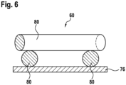
- Figure 6 shows a second distribution structure 60 of a gas distribution plate 40 according to a fifth embodiment.
- the second distribution structure 60 which is delimited by a second separating plate 76, several wire elements 80 are provided, with three wire elements 80 being visible in the illustration shown.
- Two wire elements 80 which rest directly on the second separating plate 76, run parallel to one another. Further wire elements 80 rest on the two wire elements 80, which rest directly on the second separating plate 76, and run at right angles to them. In the present case, the wire elements 80, which rest on the other wire elements 80, run straight and parallel to one another. The wire elements 80, which rest on the other wire elements 80, are therefore at a constant distance from the second separating plate 76.
- Figure 7 shows a second distribution structure 60 of a gas distribution plate 40 according to a sixth embodiment according to the invention.
- the second distribution structure 60 which is delimited by a second separating plate 76, several, in this case four, wire elements 80 are provided.
- the wire elements 80 have bends 86.
- the wire elements 80 therefore only run parallel to one another in sections. Due to the arrangement of the wire elements 80 shown here with said bends 86, channels with varying widths are formed within the second distribution structure 60 between the wire elements 80.
- first flow areas 91 which have a relatively small width.
- Second flow areas 92 are also created, which have a greater width compared to the first flow areas 91.
- the oxidant in the first flow regions 91 has a higher flow velocity than in the second flow regions 92. Furthermore, the oxidant in the first Flow areas 91 have a lower pressure than in the second flow areas 92.
Landscapes
- Chemical & Material Sciences (AREA)
- Life Sciences & Earth Sciences (AREA)
- Engineering & Computer Science (AREA)
- Manufacturing & Machinery (AREA)
- Sustainable Development (AREA)
- Sustainable Energy (AREA)
- Chemical Kinetics & Catalysis (AREA)
- Electrochemistry (AREA)
- General Chemical & Material Sciences (AREA)
- Composite Materials (AREA)
- Fuel Cell (AREA)
Description
- Die Erfindung betrifft eine Gasverteilerplatte für eine Brennstoffzelle, welche eine erste Verteilstruktur zur Verteilung eines Brennstoffs an eine erste Elektrode und eine zweite Verteilstruktur zur Verteilung eines Oxidationsmittels an eine zweite Elektrode umfasst. Die Erfindung betrifft auch eine Brennstoffzelle, die mindestens eine erfindungsgemäße Gasverteilerplatte umfasst.
- Eine Brennstoffzelle ist eine galvanische Zelle, welche die chemische Reaktionsenergie eines kontinuierlich zugeführten Brennstoffes und eines Oxidationsmittels in elektrische Energie wandelt. Eine Brennstoffzelle ist also ein elektrochemischer Energiewandler. Bei bekannten Brennstoffzellen werden insbesondere Wasserstoff (H2) und Sauerstoff (O2) in Wasser (H2O), elektrische Energie und Wärme gewandelt.
- Ein Elektrolyseur ist ein elektrochemischer Energiewandler, welcher Wasser (H2O) mittels elektrischer Energie in Wasserstoff (H2) und Sauerstoff (O2) spaltet.
- Unter anderem sind Protonenaustauschmembran (Proton-Exchange-Membran = PEM) -Brennstoffzellen bekannt. Protonenaustauschmembran-Brennstoffzellen weisen eine zentral angeordnete Membran auf, die für Protonen, also für Wasserstoffionen, durchlässig ist. Das Oxidationsmittel, insbesondere Luftsauerstoff, ist dadurch räumlich von dem Brennstoff, insbesondere Wasserstoff, getrennt.
- Protonenaustauschmembran-Brennstoffzellen weisen ferner eine Anode und eine Kathode auf. Der Brennstoff wird an der Anode der Brennstoffzelle zugeführt und katalytisch unter Abgabe von Elektronen zu Protonen oxidiert. Die Protonen gelangen durch die Membran zu der Kathode. Die abgegebenen Elektronen werden aus der Brennstoffzelle abgeleitet und fließen über einen externen Stromkreis zu der Kathode.
- Das Oxidationsmittel wird an der Kathode der Brennstoffzelle zugeführt und es reagiert durch Aufnahme der Elektronen aus dem externen Stromkreis und Protonen, die durch die Membran zur Kathode gelangt sind, zu Wasser. Das so entstandene Wasser wird aus der Brennstoffzelle abgeleitet. Die Bruttoreaktion lautet:
O2 + 4H+ + 4e- → 2H2O
- Zwischen der Anode und der Kathode der Brennstoffzelle liegt dabei eine Spannung an. Zur Erhöhung der Spannung können mehrere Brennstoffzellen mechanisch hintereinander zu einem Brennstoffzellenstapel angeordnet und elektrisch in Reihe geschaltet werden.
- Zur gleichmäßigen Verteilung des Brennstoffs an die Anode sowie zur gleichmäßigen Verteilung des Oxidationsmittels an die Kathode sind Gasverteilerplatten vorgesehen, welche auch als Bipolarplatten bezeichnet werden. Die Gasverteilerplatten weisen beispielsweise kanalartige Strukturen zur Verteilung des Brennstoffs sowie des Oxidationsmittels an die Elektroden auf. Die kanalartigen Strukturen diesen ferner zur Ableitung des bei der Reaktion entstandenen Wassers. Die Gasverteilerplatten können ferner Strukturen zur Durchleitung einer Kühlflüssigkeit durch die Brennstoffzelle zur Abführung von Wärme aufweisen.
- Aus der
DE 10 2012 221 730 A1 ist eine Brennstoffzelle mit einer gattungsgemäßen Gasverteilerplatte bekannt, welche aus zwei Plattenhälften aufgebaut ist. Dabei weist jede der beiden Plattenhälften eine Verteilstruktur auf, welche zur Verteilung der Reaktionsgase vorgesehen ist. - Auch aus der
DE 10 2014 207 594 A1 ist eine Gasverteilerplatte für eine Brennstoffzelle bekannt. Die Gasverteilerplatte weist dabei einen mäanderförmigen Kanal auf, welcher beispielsweise als Nut ausgebildet ist. Der mäanderförmige Kanal dient zur Einleitung von Wasserstoff oder Sauerstoff in die Brennstoffzelle. - Die Offenlegungsschrift
DE 10 2007 025828 A1 offenbart eine Gasverteilerplatte in Form von Bipolarplatten für eine Brennstoffzelle, umfassend eine erste Verteilerstruktur aus Drahtleiterbahnen zur Verteilung eines Brennstoffs an eine erste Elektrode und eine zweite Verteilerstruktur zur Verteilung eines Oxidationsmittels an eine zweite Elektrode. -
US 2011/183228 A1 offenbart eine Brennstoffzelle mit Sauerstoff- und Brennstoffverteilerstrukturen, wobei mindestens eine Verteilerstruktur ein Drahtelement aufweist. - Es wird eine Gasverteilerplatte für eine Brennstoffzelle vorgeschlagen, welche eine erste Verteilstruktur zur Verteilung eines Brennstoffs an eine erste Elektrode und eine zweite Verteilstruktur zur Verteilung eines Oxidationsmittels an eine zweite Elektrode umfasst. Die Gasverteilplatte kann aber auch in anderen elektrochemischen Energiewandlern, beispielsweise in einem Elektrolyseur, eingesetzt werden.
- Erfindungsgemäß sind in der zweiten Verteilstruktur mindestens zwei Drahtelemente vorgesehen, wobei diese Biegungen aufweisen und dadurch innerhalb der zweiten Verteilerstruktur zwischen den Drahtelementen Kanäle mit variierenden Breiten ausgebildet sind, wobei die Verteilstruktur von einer Trennplatte begrenzt ist, welche mit den Drahtelementen stoffschlüssig verbunden ist. Durch geeignete Anordnung des Drahtelements können gezielt Kanäle in der Verteilstruktur ausgebildet werden. Dadurch kann die Durchstömung der Verteilstruktur beeinflusst werden.
- Vorzugsweise sind die mindestens zwei Drahtelemente dabei in der zweiten Verteilstruktur vorgesehen, welche zur Verteilung des Oxidationsmittels an die zweite Elektrode sowie zur Ableitung von bei der Reaktion entstandenem Wasser dient. Mindestens ein Drahtelement kann aber auch, alternativ oder zusätzlich, in der ersten Verteilstruktur zur Verteilung eines Brennstoffs an die erste Elektrode vorgesehen sein.
- Gemäß einer vorteilhaften Ausgestaltung der Erfindung weist das Drahtelement einen runden, also kreisförmigen Querschnitt auf. Dadurch ist das Drahtelement verhältnismäßig kostengünstig und einfach zu fertigen. Aber auch andere Querschnittsformen des Drahtelements sind denkbar. Beispielsweise kann das Drahtelement auch einen ovalen, dreieckigen, viereckigen, fünfeckigen, sechseckigen oder polygonalen Querschnitt aufweisen.
- Vorzugsweise ist das Drahtelement aus einem metallischen Stoff gefertigt. Somit ist das Drahtelement elektrisch leitfähig und kann die bei der elektrochemischen Reaktion in der Brennstoffzelle freigesetzten Elektronen leiten. Als mögliche Materialien für das Drahtelement bieten sich beispielsweise korrosionsbeständige Metalle wie Kupfer, Aluminium, Silber, Gold sowie Edelstahl an. Aber auch andere, vorzugsweise elektrisch Leitfähige Materialien wie Graphit oder einfacher Stahl sind denkbar.
- Gemäß einer vorteilhaften Weiterbildung der Erfindung weist das Drahtelement eine nanostrukturierte und/oder mikrostrukturierte Oberfläche auf.
- Die nanostrukturierte und/oder mikrostrukturierte Oberfläche beeinflusst die Benetzung der Drahtelemente mit Wasser. Somit können die Drahtelemente entweder hydrophile oder hydrophobe Eigenschaften erhalten. Dies kann anhängig von den gewünschten Prozessbedingungen den Wasserabtrag verbessern oder verlangsamen. Die Nanostrukturierung, beziehungsweise die Mikrostrukturierung kann mit unterschiedlichen gängigen Methoden erfolgen, wobei dies schon bei der Herstellung der Drahtelemente erfolgen kann. Als Beispiel werden folgende Methoden genannt: elektrochemisch (beispielsweise elektrochemische Abscheidung von dreidimensionalen Kupferstrukturen oder Metallstrukturen), Plasmaätzen, CVD, PVD, mechanisches Aufrauen, Lithographie, laserbasierte Methoden (beispielsweise Strukturierung von metallischen Stoffen mit Femtosekunden-Laserpulsen).
- Zum Schutz des Drahtelements vor Korrosion, insbesondere, wenn das Drahtelement aus einem unedlen Metall wie beispielsweise Stahl gefertigt ist, kann das Drahtelement vorteilhaft mit einer Ummantelung versehen sein. Die Ummantelung enthält insbesondere einen Kunststoff, beziehungsweise ein Polymer. Um trotz der elektrisch isolierenden Ummantelung des Drahtelements eine elektrische Leitfähigkeit für die bei der elektrochemischen Reaktion in der Brennstoffzelle freigesetzten Elektronen sicherzustellen sind einige Kontaktstellen des Drahtelements mit benachbarten leitfähigen Elementen von der Ummantelung befreit. Des Weiteren kann die schützende Ummantelung derart ausgewählt werden, dass ihre elektrische Leitfähigkeit den Anforderungen genügt.
- Erfindungsgemäß ist die Verteilstruktur von einer Trennplatte begrenzt, welche mit dem Drahtelement stoffschlüssig verbunden ist. Die Trennplatte ist beispielsweise als dünnes metallisches Blech ausgebildet und trennt die Verteilstruktur beispielsweise von einer benachbarten Verteilstruktur. Zur Verbindung des Drahtelements mit der Trennplatte kommen unter anderem Verfahren wie Diffusionsfügen, Schweißen, Laserschweißen, Widerstandsschweißen, Löten, Hartlöten, Weichlöten oder Sintern zur Anwendung.
- Gemäß einer vorteilhaften Weiterbildung der Erfindung sind das Drahtelement und die Trennplatte mit einer gemeinsamen Beschichtung versehen. Die Beschichtung enthält insbesondere einen Kunststoff, beziehungsweise ein Polymer. Bei der Fertigung der Gasverteilplatte wird zunächst das Drahtelement mit der Trennplatte verbunden und anschließend wird die Beschichtung aufgebracht. Die Beschichtung dient insbesondere zum Schutz des Drahtelements sowie der Trennplatte vor Korrosion, insbesondere, wenn das Drahtelement und die Trennplatte aus einem unedlen Metall wie beispielsweise Stahl gefertigt sind.
- Erfindungsgemäß weist das Drahtelement mindestens eine Biegung auf. Durch entsprechende Anordnung des Drahtelements mit geeigneten Biegungen können innerhalb der Verteilstruktur Kanäle mit variierenden Breiten ausgebildet werden. Dadurch ergeben sich beim Durchströmen des Oxidationsmittels Druckdifferenzen in der Verteilstruktur und somit auch variierende Strömungsgeschwindigkeiten. Damit wird die Durchmischung innerhalb der Verteilstruktur verbessert.
- Gemäß einer vorteilhaften Weiterbildung der Erfindung sind mindestens zwei Drahtelemente in der Verteilstruktur vorgesehen, welche in zueinander geneigten Richtungen verlaufen. Beispielsweise sind die Drahtelemente übereinander geschichtet und verlaufen rechtwinklig zueinander. Durch eine derartige Anordnung von zwei oder mehreren Drahtelementen können Porositäten in der Verteilstruktur geschaffen werden.
- Es wird auch eine Brennstoffzelle vorgeschlagen, die mindestens eine Membran-Elektrodeneinheit mit einer ersten Elektrode und einer zweiten Elektrode, welche voneinander durch eine Membran getrennt sind, und mindestens eine erfindungsgemäße Gasverteilerplatte umfasst. Insbesondere ist die Brennstoffzelle derart aufgebaut, dass sich beidseitig an die Membran-Elektrodeneinheit jeweils eine Gasverteilerplatte anschließt.
- Die erfindungsgemäße Ausgestaltung der Gasverteilerplatte ermöglicht eine flexible Gestaltung der Verteilstruktur. Das Drahtelement kann in unterschiedlichsten Ausführungen gelegt werden und somit Kanäle mit unterschiedlichsten Geometrien bilden. Das Drahtelement kann aus unterschiedlichsten Materialien gefertigt sein. Das Drahtelement kann beschichtet, gecoated, ummantelt, oder koaxial in unterschiedliche Materialien eingebettet sein. Bei einer Anordnung mehrerer Drahtelemente übereinander können auch poröse Strukturen in der Gasverteilerplatte erzeugt werden. Durch entsprechende Variierung der Geometrie der Kanäle oder des Drahtelements können Gasdurchfluss sowie Wasserabfluss und Wasserkondensation gesteuert werden. Insbesondere können Erkenntnisse, die bei entsprechenden Simulationen gewonnen werden, verhältnismäßig schnell und einfach zur praktischen Erprobung umgesetzt werden
Durch entsprechende Bearbeitung der Oberflächen des Drahtelements können unter anderem die Benetzungseigenschaften des Drahtelements beeinflusst werden. Ferner können hydrophobe Eigenschaften der Verteilstruktur mittels der Ummantelung des Drahtelements eingestellt werden. Auch ist es denkbar, bei der Fertigung der Brennstoffzelle oder eines Brennstoffzellenstapels mit mehreren Brennstoffzellen das Drahtelement durch Anpressen kraftschlüssig in der Verteilstruktur zu halten. Eine zusätzliche Verbindung, beispielsweise durch Schweißen, kann dabei entfallen. - Ausführungsformen der Erfindung werden anhand der Zeichnungen und der nachfolgenden Beschreibung näher erläutert.
- Es zeigen:
- Figur 1
- eine schematische Darstellung eines Brennstoffzellenstapels mit mehreren Brennstoffzellen,
- Figur 2
- eine Verteilstruktur einer Gasverteilerplatte gemäß einer ersten Ausführungsform,
- Figur 3
- eine Verteilstruktur einer Gasverteilerplatte gemäß einer zweiten Ausführungsform,
- Figur 4
- eine Verteilstruktur einer Gasverteilerplatte gemäß einer dritten Ausführungsform,
- Figur 5
- eine Verteilstruktur einer Gasverteilerplatte gemäß einer vierten Ausführungsform,
- Figur 6
- eine Verteilstruktur einer Gasverteilerplatte gemäß einer fünften Ausführungsform und
- Figur 7
- eine Verteilstruktur einer Gasverteilerplatte gemäß einer erfindungsgemäßen sechsten Ausführungsform.
- In der nachfolgenden Beschreibung der Ausführungsformen der Erfindung werden gleiche oder ähnliche Elemente mit gleichen Bezugszeichen bezeichnet, wobei auf eine wiederholte Beschreibung dieser Elemente in Einzelfällen verzichtet wird. Die Figuren stellen den Gegenstand der Erfindung nur schematisch dar.
-
Figur 1 zeigt eine schematische Darstellung eines Brennstoffzellenstapels mit mehreren Brennstoffzellen 2. Jede Brennstoffzelle 2 weist eine Membran-Elektrodeneinheit 10 auf, die eine erste Elektrode 21, eine zweite Elektrode 22 und eine Membran 18 umfasst. Die beiden Elektroden 21, 22 sind auf einander gegenüber liegenden Seiten der Membran 18 angeordnet und somit voneinander durch die Membran 18 getrennt. Die erste Elektrode 21 wird im Folgenden auch als Anode 21 bezeichnet und die zweite Elektrode 22 wird im Folgenden auch als Kathode 22 bezeichnet. Die Membran 18 ist als Polymerelektrolytmembran ausgebildet. Die Membran 18 ist für Wasserstoffionen, also H+-Ionen, durchlässig. - Jede Brennstoffzelle 2 weist ferner zwei Gasverteilerplatten 40 auf, die sich beidseitig an die Membran-Elektrodeneinheit 10 anschließen. Bei der hier gezeigten Anordnung mehrerer Brennstoffzellen 2 in einem Brennstoffzellenstapel kann jede der Gasverteilerplatten 40 als zu zwei zueinander benachbart angeordneten Brennstoffzellen 2 gehörig betrachtet werden.
- Die Gasverteilerplatten 40 umfassen jeweils eine erste Verteilstruktur 50 zur Verteilung eines Brennstoffs, die der Anode 21 zugewandt ist. Die Gasverteilerplatten 40 umfassen jeweils auch eine zweite Verteilstruktur 60 zur Verteilung des Oxidationsmittels, die der Kathode 22 zugewandt ist. Die zweite Verteilstruktur 60 dient gleichzeitig zur Ableitung von bei einer Reaktion in der Brennstoffzelle 2 entstandenem Wasser.
- Die Gasverteilerplatten 40 umfassen ferner eine dritte Verteilstruktur 70, welche zwischen der ersten Verteilstruktur 50 und der zweiten Verteilstruktur 60 angeordnet ist. Die dritte Verteilstruktur 70 dient zur Durchleitung eines Kühlmittels durch die Gasverteilerplatte 40 und damit zur Kühlung der Brennstoffzelle 2.
- Die erste Verteilstruktur 50 und die dritte Verteilstruktur 70 sind durch eine erste Trennplatte 75 voneinander getrennt. Die zweite Verteilstruktur 60 und die dritte Verteilstruktur 70 sind durch eine zweite Trennplatte 76 voneinander getrennt. Die Trennplatten 75, 76 der Gasverteilerplatten 40 sind vorliegend als dünne metallische Bleche ausgebildet.
- Im Betrieb der Brennstoffzelle 2 wird Brennstoff über die erste Verteilstruktur 50 zu der Anode 21 geleitet. Ebenso wird Oxidationsmittel über die zweite Verteilstruktur 60 zu der Kathode 22 geleitet. Der Brennstoff, vorliegend Wasserstoff, wird an der Anode 21 katalytisch unter Abgabe von Elektronen zu Protonen oxidiert. Die Protonen gelangen durch die Membran 18 zu der Kathode 22. Die abgegebenen Elektronen werden aus der Brennstoffzelle 2 abgeleitet und fließen über einen externen Stromkreis zu der Kathode 22. Das Oxidationsmittel, vorliegend Luftsauerstoff, reagiert durch Aufnahme der Elektronen aus dem externen Stromkreis und Protonen, die durch die Membran 18 zu der Kathode 22 gelangt sind, zu Wasser.
-
Figur 2 zeigt eine zweite Verteilstruktur 60 einer Gasverteilerplatte 40 gemäß einer ersten Ausführungsform. In der zweiten Verteilstruktur 60, die von einer zweiten Trennplatte 76 begrenzt ist, sind mehrere, vorliegend drei, Drahtelemente 80 vorgesehen. - Die Drahtelemente 80 weisen vorliegend einen runden Querschnitt auf. Die Drahtelemente 80 sind aus einem Metall, vorliegend Aluminium, gefertigt. Dabei sind die Drahtelemente 80 stoffschlüssig mit der zweiten Trennplatte 76 verbunden.
-
Figur 3 zeigt eine zweite Verteilstruktur 60 einer Gasverteilerplatte 40 gemäß einer zweiten Ausführungsform. In der zweiten Verteilstruktur 60, die von einer zweiten Trennplatte 76 begrenzt ist, sind mehrere, vorliegend drei, Drahtelemente 80 vorgesehen. - Die Drahtelemente 80 weisen vorliegend einen ovalen Querschnitt auf. Die Drahtelemente 80 sind aus einem Metall, vorliegend Stahl, gefertigt. Dabei sind die Drahtelemente 80 stoffschlüssig mit der zweiten Trennplatte 76 verbunden. Die Drahtelemente 80 und die zweite Trennplatte 76 sind mit einer gemeinsamen Beschichtung 84 versehen. Die Beschichtung 84 enthält ein Polymer und dient zum Schutz der Drahtelemente 80 sowie der zweiten Trennplatte 76 vor Korrosion.
-
Figur 4 zeigt eine zweite Verteilstruktur 60 einer Gasverteilerplatte 40 gemäß einer dritten Ausführungsform. In der zweiten Verteilstruktur 60, die von einer zweiten Trennplatte 76 begrenzt ist, sind mehrere, vorliegend drei, Drahtelemente 80 vorgesehen. - Die Drahtelemente 80 weisen vorliegend einen runden Querschnitt auf. Die Drahtelemente 80 sind aus einem Metall, vorliegend Stahl, gefertigt. Dabei sind die Drahtelemente 80 jeweils mit einer Ummantelung 82 versehen. Die Ummantelung 82 enthält ein Polymer und dient zum Schutz der Drahtelemente 80 vor Korrosion. Die Drahtelemente 80 weisen hier nicht sichtbare Kontaktstellen auf, welche frei von der Ummantelung 82 sind. An den Kontaktstellen sind die Drahtelemente 80 stoffschlüssig mit der zweiten Trennplatte 76 verbunden.
-
Figur 5 zeigt eine zweite Verteilstruktur 60 einer Gasverteilerplatte 40 gemäß einer vierten Ausführungsform. In der zweiten Verteilstruktur 60, die von einer zweiten Trennplatte 76 begrenzt ist, sind mehrere Drahtelemente 80 vorgesehen, wobei in der gezeigten Darstellung drei Drahtelemente 80 sichtbar sind. - Dabei verlaufen zwei Drahtelemente 80, welche unmittelbar auf der zweiten Trennplatte 76 aufliegen, parallel zueinander. Weitere Drahtelemente 80 liegen auf den beiden Drahtelemente 80 auf, die unmittelbar auf der zweiten Trennplatte 76 aufliegen, und verlaufen rechtwinklig zu diesen. Die Drahtelemente 80, welche auf den anderen Drahtelementen 80 aufliegen, sind dabei gekrümmt und nähern sich in Zwischenräumen zwischen den anderen Drahtelementen 80 der zweiten Trennplatte 76 an.
-
Figur 6 zeigt eine zweite Verteilstruktur 60 einer Gasverteilerplatte 40 gemäß einer fünften Ausführungsform. In der zweiten Verteilstruktur 60, die von einer zweiten Trennplatte 76 begrenzt ist, sind mehrere Drahtelemente 80 vorgesehen, wobei in der gezeigten Darstellung drei Drahtelemente 80 sichtbar sind. - Dabei verlaufen zwei Drahtelemente 80, welche unmittelbar auf der zweiten Trennplatte 76 aufliegen, parallel zueinander. Weitere Drahtelemente 80 liegen auf den beiden Drahtelemente 80 auf, die unmittelbar auf der zweiten Trennplatte 76 aufliegen, und verlaufen rechtwinklig zu diesen. Die Drahtelemente 80, welche auf den anderen Drahtelementen 80 aufliegen, verlaufen vorliegend gerade und parallel zueinander. Die Drahtelemente 80, welche auf den anderen Drahtelementen 80 aufliegen, haben somit einen gleichbleibenden Abstand zu der zweiten Trennplatte 76.
-
Figur 7 zeigt eine zweite Verteilstruktur 60 einer Gasverteilerplatte 40 gemäß einer erfindungsgemäßen sechsten Ausführungsform. In der zweiten Verteilstruktur 60, die von einer zweiten Trennplatte 76 begrenzt ist, sind mehrere, vorliegend vier, Drahtelemente 80 vorgesehen. - Die Drahtelemente 80 weisen Biegungen 86 auf. Die Drahtelemente 80 verlaufen somit nur abschnittsweise parallel zueinander. Durch die hier gezeigte Anordnung der Drahtelemente 80 mit besagten Biegungen 86 werden innerhalb der zweiten Verteilstruktur 60 zwischen den Drahtelementen 80 Kanäle mit variierenden Breiten ausgebildet.
- Dabei entstehen erste Strömungsbereiche 91, welche eine verhältnismäßig geringe Breite aufweisen. Es entstehen auch zweite Strömungsbereiche 92, welche eine im Vergleich zu den ersten Strömungsbereichen 91 größere Breite aufweisen.
- Im Betrieb der Brennstoffzelle 2, wenn das Oxidationsmittel durch die zweite Verteilstruktur 60 strömt, hat das Oxidationsmittel in den ersten Strömungsbereichen 91 eine höhere Strömungsgeschwindigkeit als in den zweiten Strömungsbereichen 92. Ferner hat das Oxidationsmittel in den ersten Strömungsbereichen 91 einen geringeren Druck als in den zweiten Strömungsbereichen 92.
- Die Erfindung ist nicht auf die hier beschriebenen Ausführungsbeispiele und die darin hervorgehobenen Aspekte beschränkt. Vielmehr ist innerhalb des durch die Ansprüche angegebenen Bereichs eine Vielzahl von Abwandlungen möglich, die im Rahmen fachmännischen Handelns liegen.
Claims (7)
- Gasverteilerplatte (40) für eine Brennstoffzelle (2), umfassend eine erste Verteilstruktur (50) zur Verteilung eines Brennstoffs an eine erste Elektrode (21) und eine zweite Verteilstruktur (60) zur Verteilung eines Oxidationsmittels an eine zweite Elektrode (22),
dadurch gekennzeichnet, dass
in der zweiten Verteilstruktur (60) mindestens zwei Drahtelemente (80) vorgesehen sind, wobei diese Biegungen (86) aufweisen und dadurch innerhalb der zweiten Verteilstruktur (60) zwischen den Drahtelementen (80) Kanäle mit variierenden Breiten ausgebildet sind, wobei die Verteilstruktur (50, 60) von einer Trennplatte (75, 76) begrenzt ist, welche mit den Drahtelementen (80) stoffschlüssig verbunden ist. - Gasverteilerplatte (40) nach Anspruch 1, dadurch gekennzeichnet, dass die Drahtelemente (80) einen runden Querschnitt aufweisen.
- Gasverteilerplatte (40) nach einem der vorstehenden Ansprüche,
dadurch gekennzeichnet, dass
die Drahtelemente (80) aus einem metallischen Stoff gefertigt sind. - Gasverteilerplatte (40) nach einem der vorstehenden Ansprüche,
dadurch gekennzeichnet, dass
die Drahtelemente (80) eine nanostrukturierte und/oder mikrostrukturierte Oberfläche aufweisen. - Gasverteilerplatte (40) nach einem der vorstehenden Ansprüche,
dadurch gekennzeichnet, dass
die Drahtelemente (80) mit einer Ummantelung (82) versehen sind. - Gasverteilerplatte (40) nach Anspruch 1, dadurch gekennzeichnet, dass die Drahtelemente (80) und die Trennplatte (75, 76) mit einer gemeinsamen Beschichtung (84) versehen sind.
- Brennstoffzelle (2), umfassendmindestens eine Membran-Elektrodeneinheit (10) mit einer ersten Elektrode (21) und einer zweiten Elektrode (22), welche voneinander durch eine Membran (18) getrennt sind, undmindestens eine Gasverteilerplatte (40) nach einem der vorstehenden Ansprüche.
Applications Claiming Priority (2)
| Application Number | Priority Date | Filing Date | Title |
|---|---|---|---|
| DE102016226328.5A DE102016226328A1 (de) | 2016-12-29 | 2016-12-29 | Gasverteilerplatte für eine Brennstoffzelle und Brennstoffzelle |
| PCT/EP2017/083545 WO2018122040A1 (de) | 2016-12-29 | 2017-12-19 | Gasverteilerplatte für eine brennstoffzelle und brennstoffzelle |
Publications (2)
| Publication Number | Publication Date |
|---|---|
| EP3563442A1 EP3563442A1 (de) | 2019-11-06 |
| EP3563442B1 true EP3563442B1 (de) | 2024-02-07 |
Family
ID=60782219
Family Applications (1)
| Application Number | Title | Priority Date | Filing Date |
|---|---|---|---|
| EP17818134.3A Active EP3563442B1 (de) | 2016-12-29 | 2017-12-19 | Gasverteilerplatte für eine brennstoffzelle und brennstoffzelle |
Country Status (7)
| Country | Link |
|---|---|
| US (1) | US11228040B2 (de) |
| EP (1) | EP3563442B1 (de) |
| JP (1) | JP7079253B2 (de) |
| KR (1) | KR102455001B1 (de) |
| CN (1) | CN110140246B (de) |
| DE (1) | DE102016226328A1 (de) |
| WO (1) | WO2018122040A1 (de) |
Families Citing this family (3)
| Publication number | Priority date | Publication date | Assignee | Title |
|---|---|---|---|---|
| CN112864410B (zh) * | 2019-11-27 | 2022-04-01 | 国家能源投资集团有限责任公司 | 一种燃料电池及燃料电池发电系统 |
| DE102020204292A1 (de) * | 2020-04-02 | 2021-10-07 | Robert Bosch Gesellschaft mit beschränkter Haftung | Brennstoffzelleneinheit |
| US12313581B2 (en) * | 2021-09-01 | 2025-05-27 | Iowa State University Research Foundation, Inc. | Position independent and long read range resonant sensor |
Family Cites Families (11)
| Publication number | Priority date | Publication date | Assignee | Title |
|---|---|---|---|---|
| SE516741C2 (sv) * | 2001-02-27 | 2002-02-26 | Cellkraft Ab | Bipolär platta för bränslecell eller elektrokemisk reaktor samt användning av plattan i en bränslecellstack eller elektrokemisk reaktor |
| CA2474913A1 (en) * | 2002-02-05 | 2003-08-14 | Gencell Corporation | Silane coated metallic fuel cell components and methods of manufacture |
| KR100820519B1 (ko) * | 2007-03-23 | 2008-04-08 | 지에스칼텍스 주식회사 | 연료전지 스택 냉각장치 |
| DE102007025828B4 (de) * | 2007-06-02 | 2014-09-18 | Michael Martin | Verfahren zur Herstellung von Bipolar- oder Elektrodenplatten für Brennstoffzellen- oder Elektrolyseur-Stapel sowie Verfahren zur Herstellung eines Stapels von Bipolar- oder Elektrodenplatten sowie Bipolar- oder Elektrodenplatte |
| JP2010192169A (ja) * | 2009-02-16 | 2010-09-02 | Toyota Motor Corp | 燃料電池構成部材およびその製造方法 |
| US8859164B2 (en) * | 2011-02-15 | 2014-10-14 | Ford Global Technologies, Llc | Bipolar plates and electrochemical cells employing the same |
| CN103247807B (zh) | 2012-02-08 | 2015-07-08 | 武汉众宇动力系统科技有限公司 | 基于相变换热的质子交换膜燃料电池及其双极板 |
| WO2013137240A1 (ja) * | 2012-03-14 | 2013-09-19 | 日産自動車株式会社 | 固体高分子形燃料電池用膜電極接合体 |
| DE102012221730B4 (de) | 2012-11-28 | 2026-05-07 | Robert Bosch Gmbh | Verfahren zum Abdichten eines Kühlmittelraums einer Bipolarplatte einer Brennstoffzelle sowie Brennstoffzelle |
| WO2014088114A1 (ja) * | 2012-12-04 | 2014-06-12 | 国立大学法人山梨大学 | 金属対象物表面への被覆層の作製方法 |
| DE102014207594A1 (de) | 2014-04-23 | 2015-10-29 | Robert Bosch Gmbh | Bipolarplatte für eine Elektrolyse- oder Brennstoffzelle |
-
2016
- 2016-12-29 DE DE102016226328.5A patent/DE102016226328A1/de not_active Withdrawn
-
2017
- 2017-12-19 WO PCT/EP2017/083545 patent/WO2018122040A1/de not_active Ceased
- 2017-12-19 EP EP17818134.3A patent/EP3563442B1/de active Active
- 2017-12-19 US US16/475,222 patent/US11228040B2/en active Active
- 2017-12-19 KR KR1020197021881A patent/KR102455001B1/ko active Active
- 2017-12-19 CN CN201780081434.0A patent/CN110140246B/zh active Active
- 2017-12-19 JP JP2019534683A patent/JP7079253B2/ja active Active
Also Published As
| Publication number | Publication date |
|---|---|
| JP2020514969A (ja) | 2020-05-21 |
| JP7079253B2 (ja) | 2022-06-01 |
| EP3563442A1 (de) | 2019-11-06 |
| US11228040B2 (en) | 2022-01-18 |
| WO2018122040A1 (de) | 2018-07-05 |
| CN110140246A (zh) | 2019-08-16 |
| US20190341627A1 (en) | 2019-11-07 |
| KR102455001B1 (ko) | 2022-10-17 |
| KR20190097257A (ko) | 2019-08-20 |
| DE102016226328A1 (de) | 2018-07-05 |
| CN110140246B (zh) | 2022-10-04 |
Similar Documents
| Publication | Publication Date | Title |
|---|---|---|
| WO2018015189A1 (de) | Verfahren zur herstellung einer bipolarplatte für eine brennstoffzelle und brennstoffzelle | |
| DE102012209851A1 (de) | Durchlässiger Separator für eine Brennstoffzelle | |
| WO2020193055A1 (de) | Bipolarplatte für einen brennstoffzellenstapel und brennstoffzellenstapel | |
| DE102014210358A1 (de) | Brennstoffzellenstapel mit einer dummyzelle | |
| WO2018108546A2 (de) | Verfahren zur herstellung einer bipolarplatte, bipolarplatte für eine brennstoffzelle und brennstoffzelle | |
| DE102020101948B4 (de) | Separator mit Nuten auf Kammabschnitten für Brennstoffzelle | |
| DE102011018184B4 (de) | Verfahren für elektrogeformte Bipolarplatten für Brennstoffzellen | |
| EP3563442B1 (de) | Gasverteilerplatte für eine brennstoffzelle und brennstoffzelle | |
| WO2018108552A1 (de) | Bipolarplatte für eine brennstoffzelle und brennstoffzelle | |
| DE102014209049A1 (de) | Bipolarplatte und Schichtstruktur mit einer Bipolarplatte | |
| DE102017209031A1 (de) | Verfahren zur Herstellung einer Brennstoffzelle und Brennstoffzelle | |
| WO2008098791A2 (de) | Brennstoffzellenstack in leichtbauweise | |
| DE102017210664A1 (de) | Brennstoffzelle | |
| EP1897161B1 (de) | Bipolarplatte, verfahren zur herstellung einer bipolarplatte und brennstoffzellenblock-anordnung | |
| DE102020215011A1 (de) | Bipolarplatte für eine elektrochemische Zelle, Anordnung elektrochemischer Zellen und Verfahren zum Betrieb der Anordnung elektrochemischer Zellen | |
| DE112008003285B4 (de) | Anschlussplatte für eine Brennstoffzelle, die Anschlussplatte enthaltende Brennstoffzelle | |
| DE102007062033A1 (de) | Brennstoffzelle, Strömungsfeldplatte und Verfahren zur Herstellung einer Strömungsfeldplatte | |
| WO2018054580A1 (de) | Brennstoffzelle | |
| WO2020212128A1 (de) | Bipolarplatte für eine brennstoffzelle, verfahren zur herstellung einer bipolarplatte und brennstoffzelle | |
| DE102017219418A1 (de) | Gasverteilerplatte zur Gasverteilung und Strömungsführung in Elektrolyseuren und Brennstoffzellen | |
| WO2017215872A1 (de) | Verfahren zur herstellung einer bipolarplatte für eine brennstoffzelle und brennstoffzelle | |
| EP2732494B1 (de) | Elektrochemische zelle | |
| EP1755187A2 (de) | Bipolarplatte oder Elektrodenplatte für Brennstoffzellen oder Elektrolyseur-Stapel sowie ein Verfahren zur Herstellung einer Bipolarplatte oder Elektrodenplatte für Brennstoffzellen oder Elektrolyseur-Stapel | |
| DE102020203683A1 (de) | Vorrichtung zur Mediendurchführung und Verfahren zur Herstellung | |
| DE102020215013A1 (de) | Bipolarplatte für eine elektrochemische Zelle, Verfahren zur Herstellung der Bipolarplatte, Anordnung elektrochemischer Zellen und Verfahren zum Betrieb der Anordnung elektrochemischer Zellen |
Legal Events
| Date | Code | Title | Description |
|---|---|---|---|
| STAA | Information on the status of an ep patent application or granted ep patent |
Free format text: STATUS: UNKNOWN |
|
| STAA | Information on the status of an ep patent application or granted ep patent |
Free format text: STATUS: THE INTERNATIONAL PUBLICATION HAS BEEN MADE |
|
| PUAI | Public reference made under article 153(3) epc to a published international application that has entered the european phase |
Free format text: ORIGINAL CODE: 0009012 |
|
| STAA | Information on the status of an ep patent application or granted ep patent |
Free format text: STATUS: REQUEST FOR EXAMINATION WAS MADE |
|
| 17P | Request for examination filed |
Effective date: 20190729 |
|
| AK | Designated contracting states |
Kind code of ref document: A1 Designated state(s): AL AT BE BG CH CY CZ DE DK EE ES FI FR GB GR HR HU IE IS IT LI LT LU LV MC MK MT NL NO PL PT RO RS SE SI SK SM TR |
|
| AX | Request for extension of the european patent |
Extension state: BA ME |
|
| DAV | Request for validation of the european patent (deleted) | ||
| DAX | Request for extension of the european patent (deleted) | ||
| RAP1 | Party data changed (applicant data changed or rights of an application transferred) |
Owner name: ROBERT BOSCH GMBH |
|
| STAA | Information on the status of an ep patent application or granted ep patent |
Free format text: STATUS: EXAMINATION IS IN PROGRESS |
|
| 17Q | First examination report despatched |
Effective date: 20220113 |
|
| GRAP | Despatch of communication of intention to grant a patent |
Free format text: ORIGINAL CODE: EPIDOSNIGR1 |
|
| STAA | Information on the status of an ep patent application or granted ep patent |
Free format text: STATUS: GRANT OF PATENT IS INTENDED |
|
| INTG | Intention to grant announced |
Effective date: 20230808 |
|
| GRAS | Grant fee paid |
Free format text: ORIGINAL CODE: EPIDOSNIGR3 |
|
| GRAA | (expected) grant |
Free format text: ORIGINAL CODE: 0009210 |
|
| STAA | Information on the status of an ep patent application or granted ep patent |
Free format text: STATUS: THE PATENT HAS BEEN GRANTED |
|
| AK | Designated contracting states |
Kind code of ref document: B1 Designated state(s): AL AT BE BG CH CY CZ DE DK EE ES FI FR GB GR HR HU IE IS IT LI LT LU LV MC MK MT NL NO PL PT RO RS SE SI SK SM TR |
|
| REG | Reference to a national code |
Ref country code: GB Ref legal event code: FG4D Free format text: NOT ENGLISH |
|
| REG | Reference to a national code |
Ref country code: CH Ref legal event code: EP |
|
| REG | Reference to a national code |
Ref country code: IE Ref legal event code: FG4D Free format text: LANGUAGE OF EP DOCUMENT: GERMAN |
|
| REG | Reference to a national code |
Ref country code: DE Ref legal event code: R096 Ref document number: 502017015821 Country of ref document: DE |
|
| REG | Reference to a national code |
Ref country code: LT Ref legal event code: MG9D |
|
| REG | Reference to a national code |
Ref country code: NL Ref legal event code: MP Effective date: 20240207 |
|
| PG25 | Lapsed in a contracting state [announced via postgrant information from national office to epo] |
Ref country code: IS Free format text: LAPSE BECAUSE OF FAILURE TO SUBMIT A TRANSLATION OF THE DESCRIPTION OR TO PAY THE FEE WITHIN THE PRESCRIBED TIME-LIMIT Effective date: 20240607 |
|
| PG25 | Lapsed in a contracting state [announced via postgrant information from national office to epo] |
Ref country code: LT Free format text: LAPSE BECAUSE OF FAILURE TO SUBMIT A TRANSLATION OF THE DESCRIPTION OR TO PAY THE FEE WITHIN THE PRESCRIBED TIME-LIMIT Effective date: 20240207 |
|
| PG25 | Lapsed in a contracting state [announced via postgrant information from national office to epo] |
Ref country code: GR Free format text: LAPSE BECAUSE OF FAILURE TO SUBMIT A TRANSLATION OF THE DESCRIPTION OR TO PAY THE FEE WITHIN THE PRESCRIBED TIME-LIMIT Effective date: 20240508 |
|
| PG25 | Lapsed in a contracting state [announced via postgrant information from national office to epo] |
Ref country code: NL Free format text: LAPSE BECAUSE OF FAILURE TO SUBMIT A TRANSLATION OF THE DESCRIPTION OR TO PAY THE FEE WITHIN THE PRESCRIBED TIME-LIMIT Effective date: 20240207 Ref country code: HR Free format text: LAPSE BECAUSE OF FAILURE TO SUBMIT A TRANSLATION OF THE DESCRIPTION OR TO PAY THE FEE WITHIN THE PRESCRIBED TIME-LIMIT Effective date: 20240207 Ref country code: RS Free format text: LAPSE BECAUSE OF FAILURE TO SUBMIT A TRANSLATION OF THE DESCRIPTION OR TO PAY THE FEE WITHIN THE PRESCRIBED TIME-LIMIT Effective date: 20240507 |
|
| PG25 | Lapsed in a contracting state [announced via postgrant information from national office to epo] |
Ref country code: ES Free format text: LAPSE BECAUSE OF FAILURE TO SUBMIT A TRANSLATION OF THE DESCRIPTION OR TO PAY THE FEE WITHIN THE PRESCRIBED TIME-LIMIT Effective date: 20240207 |
|
| PG25 | Lapsed in a contracting state [announced via postgrant information from national office to epo] |
Ref country code: RS Free format text: LAPSE BECAUSE OF FAILURE TO SUBMIT A TRANSLATION OF THE DESCRIPTION OR TO PAY THE FEE WITHIN THE PRESCRIBED TIME-LIMIT Effective date: 20240507 Ref country code: NO Free format text: LAPSE BECAUSE OF FAILURE TO SUBMIT A TRANSLATION OF THE DESCRIPTION OR TO PAY THE FEE WITHIN THE PRESCRIBED TIME-LIMIT Effective date: 20240507 Ref country code: NL Free format text: LAPSE BECAUSE OF FAILURE TO SUBMIT A TRANSLATION OF THE DESCRIPTION OR TO PAY THE FEE WITHIN THE PRESCRIBED TIME-LIMIT Effective date: 20240207 Ref country code: LT Free format text: LAPSE BECAUSE OF FAILURE TO SUBMIT A TRANSLATION OF THE DESCRIPTION OR TO PAY THE FEE WITHIN THE PRESCRIBED TIME-LIMIT Effective date: 20240207 Ref country code: IS Free format text: LAPSE BECAUSE OF FAILURE TO SUBMIT A TRANSLATION OF THE DESCRIPTION OR TO PAY THE FEE WITHIN THE PRESCRIBED TIME-LIMIT Effective date: 20240607 Ref country code: HR Free format text: LAPSE BECAUSE OF FAILURE TO SUBMIT A TRANSLATION OF THE DESCRIPTION OR TO PAY THE FEE WITHIN THE PRESCRIBED TIME-LIMIT Effective date: 20240207 Ref country code: GR Free format text: LAPSE BECAUSE OF FAILURE TO SUBMIT A TRANSLATION OF THE DESCRIPTION OR TO PAY THE FEE WITHIN THE PRESCRIBED TIME-LIMIT Effective date: 20240508 Ref country code: FI Free format text: LAPSE BECAUSE OF FAILURE TO SUBMIT A TRANSLATION OF THE DESCRIPTION OR TO PAY THE FEE WITHIN THE PRESCRIBED TIME-LIMIT Effective date: 20240207 Ref country code: ES Free format text: LAPSE BECAUSE OF FAILURE TO SUBMIT A TRANSLATION OF THE DESCRIPTION OR TO PAY THE FEE WITHIN THE PRESCRIBED TIME-LIMIT Effective date: 20240207 Ref country code: BG Free format text: LAPSE BECAUSE OF FAILURE TO SUBMIT A TRANSLATION OF THE DESCRIPTION OR TO PAY THE FEE WITHIN THE PRESCRIBED TIME-LIMIT Effective date: 20240207 |
|
| PG25 | Lapsed in a contracting state [announced via postgrant information from national office to epo] |
Ref country code: PL Free format text: LAPSE BECAUSE OF FAILURE TO SUBMIT A TRANSLATION OF THE DESCRIPTION OR TO PAY THE FEE WITHIN THE PRESCRIBED TIME-LIMIT Effective date: 20240207 Ref country code: PT Free format text: LAPSE BECAUSE OF FAILURE TO SUBMIT A TRANSLATION OF THE DESCRIPTION OR TO PAY THE FEE WITHIN THE PRESCRIBED TIME-LIMIT Effective date: 20240607 |
|
| PG25 | Lapsed in a contracting state [announced via postgrant information from national office to epo] |
Ref country code: SE Free format text: LAPSE BECAUSE OF FAILURE TO SUBMIT A TRANSLATION OF THE DESCRIPTION OR TO PAY THE FEE WITHIN THE PRESCRIBED TIME-LIMIT Effective date: 20240207 Ref country code: PT Free format text: LAPSE BECAUSE OF FAILURE TO SUBMIT A TRANSLATION OF THE DESCRIPTION OR TO PAY THE FEE WITHIN THE PRESCRIBED TIME-LIMIT Effective date: 20240607 Ref country code: PL Free format text: LAPSE BECAUSE OF FAILURE TO SUBMIT A TRANSLATION OF THE DESCRIPTION OR TO PAY THE FEE WITHIN THE PRESCRIBED TIME-LIMIT Effective date: 20240207 Ref country code: LV Free format text: LAPSE BECAUSE OF FAILURE TO SUBMIT A TRANSLATION OF THE DESCRIPTION OR TO PAY THE FEE WITHIN THE PRESCRIBED TIME-LIMIT Effective date: 20240207 |
|
| PG25 | Lapsed in a contracting state [announced via postgrant information from national office to epo] |
Ref country code: DK Free format text: LAPSE BECAUSE OF FAILURE TO SUBMIT A TRANSLATION OF THE DESCRIPTION OR TO PAY THE FEE WITHIN THE PRESCRIBED TIME-LIMIT Effective date: 20240207 |
|
| PG25 | Lapsed in a contracting state [announced via postgrant information from national office to epo] |
Ref country code: SM Free format text: LAPSE BECAUSE OF FAILURE TO SUBMIT A TRANSLATION OF THE DESCRIPTION OR TO PAY THE FEE WITHIN THE PRESCRIBED TIME-LIMIT Effective date: 20240207 |
|
| PG25 | Lapsed in a contracting state [announced via postgrant information from national office to epo] |
Ref country code: EE Free format text: LAPSE BECAUSE OF FAILURE TO SUBMIT A TRANSLATION OF THE DESCRIPTION OR TO PAY THE FEE WITHIN THE PRESCRIBED TIME-LIMIT Effective date: 20240207 Ref country code: CZ Free format text: LAPSE BECAUSE OF FAILURE TO SUBMIT A TRANSLATION OF THE DESCRIPTION OR TO PAY THE FEE WITHIN THE PRESCRIBED TIME-LIMIT Effective date: 20240207 |
|
| PG25 | Lapsed in a contracting state [announced via postgrant information from national office to epo] |
Ref country code: SK Free format text: LAPSE BECAUSE OF FAILURE TO SUBMIT A TRANSLATION OF THE DESCRIPTION OR TO PAY THE FEE WITHIN THE PRESCRIBED TIME-LIMIT Effective date: 20240207 |
|
| PG25 | Lapsed in a contracting state [announced via postgrant information from national office to epo] |
Ref country code: SM Free format text: LAPSE BECAUSE OF FAILURE TO SUBMIT A TRANSLATION OF THE DESCRIPTION OR TO PAY THE FEE WITHIN THE PRESCRIBED TIME-LIMIT Effective date: 20240207 Ref country code: SK Free format text: LAPSE BECAUSE OF FAILURE TO SUBMIT A TRANSLATION OF THE DESCRIPTION OR TO PAY THE FEE WITHIN THE PRESCRIBED TIME-LIMIT Effective date: 20240207 Ref country code: RO Free format text: LAPSE BECAUSE OF FAILURE TO SUBMIT A TRANSLATION OF THE DESCRIPTION OR TO PAY THE FEE WITHIN THE PRESCRIBED TIME-LIMIT Effective date: 20240207 Ref country code: EE Free format text: LAPSE BECAUSE OF FAILURE TO SUBMIT A TRANSLATION OF THE DESCRIPTION OR TO PAY THE FEE WITHIN THE PRESCRIBED TIME-LIMIT Effective date: 20240207 Ref country code: DK Free format text: LAPSE BECAUSE OF FAILURE TO SUBMIT A TRANSLATION OF THE DESCRIPTION OR TO PAY THE FEE WITHIN THE PRESCRIBED TIME-LIMIT Effective date: 20240207 Ref country code: CZ Free format text: LAPSE BECAUSE OF FAILURE TO SUBMIT A TRANSLATION OF THE DESCRIPTION OR TO PAY THE FEE WITHIN THE PRESCRIBED TIME-LIMIT Effective date: 20240207 |
|
| REG | Reference to a national code |
Ref country code: DE Ref legal event code: R097 Ref document number: 502017015821 Country of ref document: DE |
|
| PG25 | Lapsed in a contracting state [announced via postgrant information from national office to epo] |
Ref country code: IT Free format text: LAPSE BECAUSE OF FAILURE TO SUBMIT A TRANSLATION OF THE DESCRIPTION OR TO PAY THE FEE WITHIN THE PRESCRIBED TIME-LIMIT Effective date: 20240207 |
|
| PLBE | No opposition filed within time limit |
Free format text: ORIGINAL CODE: 0009261 |
|
| STAA | Information on the status of an ep patent application or granted ep patent |
Free format text: STATUS: NO OPPOSITION FILED WITHIN TIME LIMIT |
|
| PG25 | Lapsed in a contracting state [announced via postgrant information from national office to epo] |
Ref country code: IT Free format text: LAPSE BECAUSE OF FAILURE TO SUBMIT A TRANSLATION OF THE DESCRIPTION OR TO PAY THE FEE WITHIN THE PRESCRIBED TIME-LIMIT Effective date: 20240207 |
|
| 26N | No opposition filed |
Effective date: 20241108 |
|
| PG25 | Lapsed in a contracting state [announced via postgrant information from national office to epo] |
Ref country code: SI Free format text: LAPSE BECAUSE OF FAILURE TO SUBMIT A TRANSLATION OF THE DESCRIPTION OR TO PAY THE FEE WITHIN THE PRESCRIBED TIME-LIMIT Effective date: 20240207 |
|
| PG25 | Lapsed in a contracting state [announced via postgrant information from national office to epo] |
Ref country code: MC Free format text: LAPSE BECAUSE OF FAILURE TO SUBMIT A TRANSLATION OF THE DESCRIPTION OR TO PAY THE FEE WITHIN THE PRESCRIBED TIME-LIMIT Effective date: 20240207 |
|
| REG | Reference to a national code |
Ref country code: CH Ref legal event code: PL |
|
| PG25 | Lapsed in a contracting state [announced via postgrant information from national office to epo] |
Ref country code: LU Free format text: LAPSE BECAUSE OF NON-PAYMENT OF DUE FEES Effective date: 20241219 |
|
| GBPC | Gb: european patent ceased through non-payment of renewal fee |
Effective date: 20241219 |
|
| REG | Reference to a national code |
Ref country code: BE Ref legal event code: MM Effective date: 20241231 |
|
| PG25 | Lapsed in a contracting state [announced via postgrant information from national office to epo] |
Ref country code: BE Free format text: LAPSE BECAUSE OF NON-PAYMENT OF DUE FEES Effective date: 20241231 Ref country code: GB Free format text: LAPSE BECAUSE OF NON-PAYMENT OF DUE FEES Effective date: 20241219 |
|
| PG25 | Lapsed in a contracting state [announced via postgrant information from national office to epo] |
Ref country code: FR Free format text: LAPSE BECAUSE OF NON-PAYMENT OF DUE FEES Effective date: 20241231 |
|
| PG25 | Lapsed in a contracting state [announced via postgrant information from national office to epo] |
Ref country code: CH Free format text: LAPSE BECAUSE OF NON-PAYMENT OF DUE FEES Effective date: 20241231 |
|
| PG25 | Lapsed in a contracting state [announced via postgrant information from national office to epo] |
Ref country code: IE Free format text: LAPSE BECAUSE OF NON-PAYMENT OF DUE FEES Effective date: 20241219 |
|
| REG | Reference to a national code |
Ref country code: AT Ref legal event code: MM01 Ref document number: 1655943 Country of ref document: AT Kind code of ref document: T Effective date: 20241219 |
|
| PGFP | Annual fee paid to national office [announced via postgrant information from national office to epo] |
Ref country code: DE Payment date: 20260223 Year of fee payment: 9 |
|
| PG25 | Lapsed in a contracting state [announced via postgrant information from national office to epo] |
Ref country code: AT Free format text: LAPSE BECAUSE OF NON-PAYMENT OF DUE FEES Effective date: 20241219 |