EP3562733B1 - Pièce de structure arrière d'un véhicule automobile à liaisons continues - Google Patents
Pièce de structure arrière d'un véhicule automobile à liaisons continues Download PDFInfo
- Publication number
- EP3562733B1 EP3562733B1 EP17825580.8A EP17825580A EP3562733B1 EP 3562733 B1 EP3562733 B1 EP 3562733B1 EP 17825580 A EP17825580 A EP 17825580A EP 3562733 B1 EP3562733 B1 EP 3562733B1
- Authority
- EP
- European Patent Office
- Prior art keywords
- structural part
- components
- continuous
- pillar
- segments
- Prior art date
- Legal status (The legal status is an assumption and is not a legal conclusion. Google has not performed a legal analysis and makes no representation as to the accuracy of the status listed.)
- Active
Links
- 239000004033 plastic Substances 0.000 claims description 15
- 229920003023 plastic Polymers 0.000 claims description 15
- 239000000463 material Substances 0.000 claims description 14
- 229920001169 thermoplastic Polymers 0.000 claims description 6
- 239000004416 thermosoftening plastic Substances 0.000 claims description 6
- 239000000853 adhesive Substances 0.000 claims description 5
- 230000001070 adhesive effect Effects 0.000 claims description 5
- 239000011324 bead Substances 0.000 claims description 4
- 229910052751 metal Inorganic materials 0.000 claims description 4
- 239000002184 metal Substances 0.000 claims description 4
- 239000000470 constituent Substances 0.000 description 13
- 238000005304 joining Methods 0.000 description 13
- 239000000835 fiber Substances 0.000 description 10
- 239000004744 fabric Substances 0.000 description 4
- 230000003014 reinforcing effect Effects 0.000 description 3
- 239000012783 reinforcing fiber Substances 0.000 description 3
- 229920005989 resin Polymers 0.000 description 3
- 239000011347 resin Substances 0.000 description 3
- 229920001187 thermosetting polymer Polymers 0.000 description 3
- 238000003466 welding Methods 0.000 description 3
- 229920000049 Carbon (fiber) Polymers 0.000 description 2
- 239000003677 Sheet moulding compound Substances 0.000 description 2
- 239000004917 carbon fiber Substances 0.000 description 2
- 239000003365 glass fiber Substances 0.000 description 2
- 239000003292 glue Substances 0.000 description 2
- 239000011159 matrix material Substances 0.000 description 2
- BASFCYQUMIYNBI-UHFFFAOYSA-N platinum Chemical compound [Pt] BASFCYQUMIYNBI-UHFFFAOYSA-N 0.000 description 2
- 229920000642 polymer Polymers 0.000 description 2
- 230000002787 reinforcement Effects 0.000 description 2
- 229920006305 unsaturated polyester Polymers 0.000 description 2
- 239000004593 Epoxy Substances 0.000 description 1
- 101000860338 Homo sapiens Protein CUSTOS Proteins 0.000 description 1
- 239000004952 Polyamide Substances 0.000 description 1
- 102100028459 Protein CUSTOS Human genes 0.000 description 1
- 229910000831 Steel Inorganic materials 0.000 description 1
- 239000000654 additive Substances 0.000 description 1
- 238000004026 adhesive bonding Methods 0.000 description 1
- TWFZGCMQGLPBSX-UHFFFAOYSA-N carbendazim Chemical compound C1=CC=C2NC(NC(=O)OC)=NC2=C1 TWFZGCMQGLPBSX-UHFFFAOYSA-N 0.000 description 1
- 230000006835 compression Effects 0.000 description 1
- 238000007906 compression Methods 0.000 description 1
- 238000000151 deposition Methods 0.000 description 1
- 239000000945 filler Substances 0.000 description 1
- 238000002347 injection Methods 0.000 description 1
- 239000007924 injection Substances 0.000 description 1
- 238000001746 injection moulding Methods 0.000 description 1
- 230000010354 integration Effects 0.000 description 1
- 238000000034 method Methods 0.000 description 1
- 238000000465 moulding Methods 0.000 description 1
- 229910052697 platinum Inorganic materials 0.000 description 1
- 229920002647 polyamide Polymers 0.000 description 1
- -1 polybutylene terephthalate Polymers 0.000 description 1
- 229920001707 polybutylene terephthalate Polymers 0.000 description 1
- 229920000728 polyester Polymers 0.000 description 1
- 239000000243 solution Substances 0.000 description 1
- 239000010959 steel Substances 0.000 description 1
- 239000004634 thermosetting polymer Substances 0.000 description 1
- 229920001567 vinyl ester resin Polymers 0.000 description 1
Images


Classifications
-
- B—PERFORMING OPERATIONS; TRANSPORTING
- B62—LAND VEHICLES FOR TRAVELLING OTHERWISE THAN ON RAILS
- B62D—MOTOR VEHICLES; TRAILERS
- B62D25/00—Superstructure or monocoque structure sub-units; Parts or details thereof not otherwise provided for
- B62D25/04—Door pillars ; windshield pillars
-
- B—PERFORMING OPERATIONS; TRANSPORTING
- B62—LAND VEHICLES FOR TRAVELLING OTHERWISE THAN ON RAILS
- B62D—MOTOR VEHICLES; TRAILERS
- B62D25/00—Superstructure or monocoque structure sub-units; Parts or details thereof not otherwise provided for
- B62D25/08—Front or rear portions
-
- B—PERFORMING OPERATIONS; TRANSPORTING
- B62—LAND VEHICLES FOR TRAVELLING OTHERWISE THAN ON RAILS
- B62D—MOTOR VEHICLES; TRAILERS
- B62D27/00—Connections between superstructure or understructure sub-units
- B62D27/02—Connections between superstructure or understructure sub-units rigid
- B62D27/026—Connections by glue bonding
-
- B—PERFORMING OPERATIONS; TRANSPORTING
- B62—LAND VEHICLES FOR TRAVELLING OTHERWISE THAN ON RAILS
- B62D—MOTOR VEHICLES; TRAILERS
- B62D29/00—Superstructures, understructures, or sub-units thereof, characterised by the material thereof
- B62D29/04—Superstructures, understructures, or sub-units thereof, characterised by the material thereof predominantly of synthetic material
- B62D29/046—Combined superstructure and frame, i.e. monocoque constructions
-
- B—PERFORMING OPERATIONS; TRANSPORTING
- B62—LAND VEHICLES FOR TRAVELLING OTHERWISE THAN ON RAILS
- B62D—MOTOR VEHICLES; TRAILERS
- B62D29/00—Superstructures, understructures, or sub-units thereof, characterised by the material thereof
- B62D29/04—Superstructures, understructures, or sub-units thereof, characterised by the material thereof predominantly of synthetic material
- B62D29/048—Connections therefor, e.g. joints
Definitions
- the present invention relates to the technical field of structural parts of motor vehicles, and in particular to the field of structural parts serving to constitute the rear of the structure of a vehicle.
- a drawback of the state of the art is that the stiffness of a body formed from several parts welded together depends on the quality and above all on the number of weld points. It is for this reason that the welding points of a vehicle skeleton are quite close together. However, as close together as they are, the weld points leave between them parts of sheet that are not integral, which weakens the assembly and can cause stress concentrations. Another drawback is that the number of sheets forming a structural part can be very high, which complicates the assembly line. Another drawback is that both the density of the metal used and the number of sheets leads to a high total weight, which goes against the objectives pursued by manufacturers, who are systematically looking for lightening solutions.
- An object of the invention is a rear structural part of a motor vehicle, comprising at least one rear side pillar consisting of a set of components assembled together, characterized in that the components are mainly made of plastic and in that at least some of the components are joined to each other along continuous joining segments, characterized in that the continuous joining segments have a minimum length each of 10 cm and leave between them discontinuities of at most 10 mm and in that all the pairs of facing surfaces belonging to the constituents which are not secured to each other are spaced, two by two in a pair, by at least 7 mm.
- An advantage of continuous joining segments is that they provide an uninterrupted connection between the constituents of the pillar, which increases the stiffness and resistance of the latter.
- plastic material is understood to mean a material consisting of a resin matrix and optionally additives, fibers and fillers.
- the plastic material is here a molded or overmolded material, generally by injection.
- the term “predominantly made of plastic” is understood to mean a part which contains at least 50% by weight of plastic.
- a sheet metal part metallic which would be locally overmolded with plastic material representing less than this percentage of the total weight of the part would not be considered, within the meaning of the invention, as made of plastic.
- the rear side pillar is that which is often referred to as “pillar C” by those skilled in the art.
- the plastic material is a polymer, with which chopped fibers are mixed.
- the polymer is chosen from the list consisting of: epoxy; unsaturated polyester; vinyl ester; polyamide; polybutylene terephthalate.
- the plastic material is reinforced with reinforcing fibers, preferably glass fibers or carbon fibers, present in a proportion of between 30% and 60% by weight of the total of matter.
- the reinforcing fibers are chopped fibers embedded in the plastic material of at least one of the constituents.
- the reinforcing fibers of a component are completed by continuous unidirectional fibers or in the form of fabrics, present in reinforcing pieces made up of these fibers embedded in a plastic material which can be the same as that of the component or another plastic material chemically compatible with that of the component.
- the continuous joining segments are adhesive beads.
- the adhesive beads have a width of between 8 mm and 25 mm, preferably between 10 and 20 mm.
- the continuous joining segments are thermoplastic weld lines.
- the continuous joining segments each have a minimum length of 10 cm and leave between them discontinuities of at most 10 mm.
- the value of 10 cm is a lower limit which makes it possible to characterize the continuous nature of a joining segment according to the invention.
- the two surfaces of the same pair are joined together by joining segments. continuous.
- all the pairs of facing surfaces belonging to the constituents which are not secured to each other are spaced, two by two in a pair, by at least 7 mm.
- At least one of the constituents comprises a metal insert.
- the structural part is of the type comprising two rear lateral pillars joined by an upper cross member.
- the two rear side pillars are joined by a floor.
- one of the three components is secured to a body panel along continuous securing segments.
- An advantage of joining with a body panel is that the pillar has an even greater stiffness at the location of the body panel, because this body panel adds its own inertia to the assembly already formed by the constituents assembled by them. continuous joining segments.
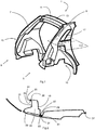
- FIG. 1 the rear of a motor vehicle structure 1 has been shown very schematically.
- This structure 1 comprises a left side 3 and a right side 5, respectively formed by a left pillar 7 and a right pillar 9.
- the two pillars 7, 9 are connected by one, or even more than one, upper cross member 11 which closes the rear of the roof 13, also referred to as the roof (not fully shown).
- a floor (not shown) connects the bottom of the two pillars 7, 9.
- the right side 5 and the left side 3 each have a wheel arch 15 for a rear wheel (not shown), as well as an opening for a rear quarter window 17.
- Other openings may be provided in the structural part 1, to lighten it or to fulfill functions specific to the vehicle in question.
- the structure 1 delimits, towards the rear of the vehicle, a rear ring, which is the zone on which a tailgate 55 ( figure 6 ) movably mounted on the rear structure 1 comes to rest in the closed position.
- Each pillar 7, 9 is formed from several components mainly made of plastic material, superimposed on each other and fixed together by at least one continuous joining segment.
- the components are two in number: an internal component 19 and an external component 21, which can be clearly distinguished on the section of the figure 2 and on the exploded view of the figure 3 .
- the internal component 19 extends towards the front of the vehicle, delimiting the contours of the rear quarter panel 17 as well as the wheel arch 15. It has flat edges 23 facing outwards which are continuous at various places and in particular along its edge. inner ridge 25 bordering the pillar 7, 9, as well as along its outer ridge 27 bordering the same pillar 7, 9.
- the external component 21 extends all along the pillar 7, 9 and covers the internal component 19.
- the external component 21 comprises flat edges 29 facing inwardly, continuous at various places and in particular on its longitudinal edges 31.
- the flat rims 23 facing outwardly of the internal component 19 and the flat rims 29 facing the interior of the external component 21 are superimposable, that is to say that their shapes coincide and they can be applied continuously. against each other, so that they can be glued or welded to each other continuously.
- the term “continuous application” is understood to mean the fact that two facing edges are spaced from each other by a distance less than the thickness of a layer of adhesive. The distance is therefore not necessarily zero between the two edges. Depending on the glue, this thickness will vary between 0.8 mm and 1.5 mm. In the case of fixing by welding, this distance would be zero.
- the fastening is a glue
- the fastening is a glue
- the two surfaces of the same pair are joined together by continuous joining segments.
- the securing between the components 19, 21 is ensured by continuous securing segments, that is to say that the internal constituent 19 and the outer constituent 21 are secured to one another along segments which do not have of intrinsic discontinuity, that is to say that each segment is continuous from one of its ends to the other and that several segments can also be placed end to end to ensure the connection of the internal component 19 and the external component 21
- the continuous bonding segments are bonding segments.
- the two constituents 19, 21 assembled due to their securing by the continuous securing segments, form a hollow body 33, which gives the pillar 7, 9 great rigidity .
- Each of the components 19, 21 is made of SMC (for "sheet molding compound") made of unsaturated polyester, to which are mixed chopped glass fibers or chopped carbon fibers, as well as possibly, in places, pieces (or “strips") of reinforcements in unidirectional continuous fibers or in the form of fabrics, embedded in the same thermosetting polymer.
- SMC sheet molding compound
- Each component was obtained by depositing, in a compression mold, blanks of material mixing a matrix of thermosetting resin such as polyester and chopped fibers and pieces of local reinforcement, made of unidirectional continuous fibers or in the form of fabrics, mixed. to another compatible esteric thermosetting resin.
- one of the constituents 19, 21 is made of thermoplastic and obtained by injection molding of a thermoplastic mixed with chopped fibers, comprising a local reinforcing strip made of unidirectional continuous fibers or in the form of fabrics, mixed with a material. plastic chemically compatible with the thermoplastic integrated into the component. This integration can result from adding the web after molding, by a fixing technique such as thermoplastic welding, well known to those skilled in the art and which will not be detailed here.
- a wing 35 which is a body panel which covers the wheel arch 15 and the entire rear pillar of the vehicle.
- This wing 35 is glued to the components 19, 21. More precisely, as seen on the figure 2 , the wing 35 is glued, towards the front in the direction of travel of the vehicle, to the internal component 19 by the front edges 37 for gluing the skin of the latter and, towards the rear, to the external component 21 by the edges back 39 of skin bonding of the latter.
- the wing 35 helps to complete the hollow body 33 and therefore to increase the rigidity of the set of components 19, 21, but it is not essential for compliance with the specifications of rigidity of the structure 1 of the vehicle, because the invention already makes it possible to close the section formed by the internal component 19 and the external component 21 to form the hollow body 33.
- the structural part 1 forms a rear ring capable of receiving a tailgate 55 ( figure 6 ).
- This rear ring carries a seal seat for a tailgate seal (not shown) and this seat is formed by the outer component 21 extending over the entire height of the ring.
- the internal component 19 is covered by the external component 21 over the entire height of the pillar 7, 9, including the upper angle of the ring 41, where it can be seen that the outer component 21 is curved to connect with the upper cross member 11.
- An end portion 47 of the upper cross member 11 covers the outer component 21 as well as the internal component 19.
- the upper cross member 11 constitutes a third component which is superimposed on the other two components 19, 21, so that these three components form between them two hollow bodies 49, which have a common party wall formed by the external component 21.
- the three components that are the internal component 19, the external component 21 and the cross member upper 11, are connected continuously by continuous joining segments.
- the outer wall of the two hollow bodies 49 is made of the superposition of the outer component 21 and of the end portion 47 of the upper cross member 11. As seen in the section of the figure 6 , this superposition is locally direct - that is to say that the distance is zero between the upper cross member 11 and the external component 21 - in a substantially horizontal location of the ring which receives a plate 51 reinforcing the fixing of a hinge 53 of the tailgate 55, the screws 57 of which sandwich the upper cross member 11 and the external component 21.
- Reference Designated object 1 ... Structure 3 ... Left side 5 ... Right side 7 ... Left pillar 9 ... Right pillar 11 ... Upper cross member 13 ... The back of the roof 15 ... Tire tracks 17 ... Custos 19 ... Internal component 21 ... External component 23 ... Flat edges facing outwards 25 ... Inner ridge 27 ... Outer ridge 29 ... Flat edges facing inward 31 ... Longitudinal edges 33 ... Hollow body 35 ... Wing 37 ... Skin bonding front edges 39 ... Skin Bonding Back Edges 41 ... Upper ring angle 47 ... End portion of the top rail 49 ... Two hollow bodies 51 ... Platinum 53 Hinge 55 ... Tailgate 57 ... Screw 59 ... Tailgate skin 61 ... Roof skin
Landscapes
- Engineering & Computer Science (AREA)
- Chemical & Material Sciences (AREA)
- Combustion & Propulsion (AREA)
- Transportation (AREA)
- Mechanical Engineering (AREA)
- Architecture (AREA)
- Structural Engineering (AREA)
- Body Structure For Vehicles (AREA)
Description
- La présente invention concerne le domaine technique des pièces de structure de véhicules automobiles, et notamment le domaine des pièces de structure servant à constituer l'arrière de la structure d'un véhicule.
- Dans l'état de la technique, tel que les documents
FR2983817A1 DE102010014574A1 ,DE102012210764 A1 etDE102012210764 A1 , on sait que les pièces de structure formant le squelette du véhicule, désigné parfois caisse ou châssis, sont formées par assemblage de tôles d'acier, soudées les unes aux autres par des points de soudure rapprochés mais discontinus. - Un inconvénient de l'état de la technique est que la raideur d'un corps formé de plusieurs pièces soudées entre elles dépend de la qualité et surtout du nombre de points de soudure. C'est pour cette raison que les points de soudure d'un squelette de véhicule sont assez rapprochés. Cependant, aussi rapprochés soient-ils, les points de soudure laissent entre eux des parties de tôle non solidaires, ce qui fragilise l'ensemble et peut occasionner des concentrations de contraintes. Un autre inconvénient est que le nombre de tôles formant une pièce de structure peut être très élevé, ce qui complexifie la chaine d'assemblage. Un autre inconvénient est qu'à la fois la densité du métal utilisé et le nombre de tôles entraine un poids total élevé, ce qui va à l'encontre des objectifs poursuivis par les constructeurs, qui recherchent systématiquement des solutions d'allègement.
- Un objet de l'invention est une pièce de structure arrière d'un véhicule automobile, comprenant au moins un pilier latéral arrière constitué par un ensemble de constituants assemblés les uns aux autres, caractérisée en ce que les constituants sont majoritairement réalisés en matière plastique et en ce que certains au moins des constituants sont solidarisés les uns aux autres le long de segments de solidarisation continus, caractérisée en ce que les segments de solidarisation continus présentent une longueur minimale chacun de 10 cm et laissent entre eux des discontinuités d'au maximum 10 mm et en ce que toutes les paires de surfaces en vis-à-vis appartenant aux constituants qui sont non solidarisées entre elles sont distantes, deux à deux dans une paire, d'au moins 7 mm.
- Un avantage des segments de solidarisation continus est qu'ils procurent une liaison sans interruption entre les constituants du pilier, ce qui accroit la raideur et la résistance de ce dernier.
- Dans la présente description, on entend par matière plastique, une matière constituée par une matrice en résine et éventuellement des additifs, des fibres et des charges. La matière plastique est ici une matière moulée ou surmoulée, en général par injection.
- On entend par "majoritairement réalisée en matière plastique" une pièce qui contient au moins 50% en poids de matière plastique. Ainsi, une pièce en tôle métallique qui serait localement surmoulée de matière plastique représentant moins de ce pourcentage du poids total de la pièce ne serait pas considérée, au sens de l'invention, comme réalisée en matière plastique. Selon l'invention, le pilier latéral arrière est celui qui est souvent désigné "pilier C" par l'homme du métier.
- Selon un mode de réalisation particulier de la pièce de structure, la matière plastique est un polymère, auquel sont mélangées des fibres coupées.
- Selon un mode de réalisation particulier de la pièce de structure, le polymère est choisi parmi la liste constituée de : époxy ; polyester insaturé ; vinylester ; polyamide ; polybutylène téréphtalate.
- Selon un mode de réalisation particulier de la pièce de structure, la matière plastique est renforcée de fibres de renfort, de préférence des fibres de verre ou des fibres de carbone, présentes dans une proportion comprise entre 30% et 60% en poids du total de la matière.
- Selon un mode de réalisation particulier de la pièce de structure, les fibres de renfort sont des fibres coupées noyées dans la matière plastique d'un au moins des constituants.
- Selon un mode de réalisation particulier de la pièce de structure, les fibres de renfort d'un constituant sont complétées par des fibres continues unidirectionnelles ou sous forme de tissus, présentes dans de morceaux de renforts constitués de ces fibres noyées dans une matière plastique qui peut être la même que celle du constituant ou une autre matière plastique chimiquement compatible avec celle du constituant.
- Selon un mode de réalisation particulier de la pièce de structure, les segments de solidarisation continus sont des cordons de collage.
- Selon un mode de réalisation particulier de la pièce de structure, les cordons de collage ont une largeur comprise entre 8 mm et 25 mm, de préférence entre 10 et 20 mm.
- Selon un mode de réalisation particulier de la pièce de structure, les segments de solidarisation continus sont des lignes de soudure thermoplastique.
- Selon la pièce de structure, objet de l'invention, les segments de solidarisation continus présentent chacun une longueur minimale de 10 cm et laissent entre eux des discontinuités d'au maximum 10 mm.
- La valeur de 10 cm est une limite inférieure qui permet de caractériser le caractère continu d'un segment de solidarisation selon l'invention.
- Selon un mode de réalisation particulier de la pièce de structure, dans toutes les paires de surfaces en vis-à-vis appartenant aux constituants, les deux surfaces d'une même paire sont solidarisées entre elles par des segments de solidarisation continus.
- Selon la pièce de structure, objet de l'invention, toutes les paires de surfaces en vis-à-vis appartenant aux constituants qui sont non solidarisées entre elles sont distantes, deux à deux dans une paire, d'au moins 7 mm.
- Selon un mode de réalisation particulier de la pièce de structure, l'un au moins des constituants comprend un insert métallique.
- Selon un mode de réalisation particulier, la pièce de structure est du type comprenant deux piliers latéraux arrières réunis par une traverse supérieure.
- Selon un mode de réalisation particulier de la pièce de structure, les deux piliers latéraux arrières sont réunis par un plancher.
- Selon un mode de réalisation particulier de la pièce de structure, l'un des trois constituants est solidarisé à un panneau de carrosserie le long de segments de solidarisation continus.
- Un avantage de la solidarisation avec un panneau de carrosserie est que le pilier a une raideur encore plus grande à l'emplacement du panneau de carrosserie, car ce panneau de carrosserie ajoute sa propre inertie à l'ensemble déjà constitué par les constituants assemblés par les segments de solidarisation continus.
- L'invention sera mieux comprise à la lecture des figures annexées, qui sont fournies à titre d'exemples et ne présentent aucun caractère limitatif, dans lesquelles :
- la
figure 1 est un croquis général d'une structure arrière de véhicule automobile comprenant notamment un pilier latéral arrière, - la
figure 2 est une section selon le plan horizontal II-II de lafigure 1 , du pilier latéral arrière portant une aile, - la
figure 3 est une vue éclatée de la structure arrière de lafigure 1 , avant assemblage des pièces dont elle est constituée, - la
figure 4 est une vue tridimensionnelle et en coupe selon II-II montrant l'aile solidarisée à la pièce de structure, - la
figure 5 est une vue tridimensionnelle d'un coin supérieur du pilier latéral arrière desfigures 2 et3 , - la
figure 6 est une section selon le plan vertical VI-VI de lafigure 5 . - Sur la
figure 1 , on a représenté très schématiquement l'arrière d'une structure 1 de véhicule automobile. Cette structure 1 comprend un côté gauche 3 et un côté droit 5, respectivement formés par un pilier gauche 7 et un pilier droit 9. Les deux piliers 7, 9 sont reliés par une, voire plus d'une, traverse supérieure 11 qui ferme l'arrière du toit 13, également désigné pavillon (non représenté entièrement). Un plancher (non représenté) relie le bas des deux piliers 7, 9. - Le côté droit 5 et le côté gauche 3 comportent chacun un passage de roue 15 pour une roue arrière (non représentée), ainsi qu'une ouverture pour une vitre de custode 17. D'autres ouvertures peuvent être prévues dans la pièce de structure 1, pour l'alléger ou pour remplir des fonctions spécifiques au véhicule considéré. Ces détails géométriques ne sont pas davantage décrits car ils ne sont pas pertinents pour décrire la présente invention.
- La structure 1 délimite, vers l'arrière du véhicule, un anneau arrière, qui est la zone sur laquelle un hayon 55 (
figure 6 ) monté mobile sur la structure 1 arrière vient prendre appui en position fermée. - Chaque pilier 7, 9 est formé de plusieurs constituants majoritairement réalisés en matière plastique, superposés les uns sur les autres et fixés entre eux par au moins un segment de solidarisation continu. Dans l'exemple, les constituants sont au nombre de deux : un constituant interne 19 et un constituant externe 21, que l'on distingue nettement sur la section de la
figure 2 et sur l'éclaté de lafigure 3 . - Le constituant interne 19 s'étend vers l'avant du véhicule en délimitant les contours de la custode 17 ainsi que le passage de roue 15. Il comporte des rebords plats 23 tournés vers l'extérieur continus en différents endroits et notamment le long de son arête intérieure 25 bordant le pilier 7, 9, ainsi que le long de son arête extérieure 27 bordant le même pilier 7, 9.
- Le constituant externe 21 s'étend tout le long du pilier 7, 9 et recouvre le constituant interne 19. Le constituant externe 21 comporte des rebords plats 29 tournés vers l'intérieur, continus en différents endroits et notamment sur ses arêtes longitudinales 31.
- Les rebords plats 23 tournés vers l'extérieur du constituant interne 19 et les rebords plats 29 tournés vers l'intérieur du constituant externe 21 sont superposables, c'est-à-dire que leurs formes coïncident et qu'ils peuvent s'appliquer continûment l'un contre l'autre, de manière à pouvoir être collés ou soudés l'un à l'autre de façon continue. Dans ce mode de réalisation, on entend par s'appliquer continument le fait que deux rebords en vis-à-vis sont distants l'un de l'autre d'une distance inférieure à l'épaisseur d'une couche de colle. La distance n'est donc pas nécessairement nulle entre les deux rebords. En fonction de la colle, cette épaisseur varier entre 0,8 mm et 1,5 mm. Dans le cas d'une fixation par soudure, cette distance serait nulle. Dans le présent mode de réalisation où la fixation est un collage, dans le pilier 7, 9, il n'existe pas deux paires de surfaces des constituants 19, 21 qui soient en vis-à-vis l'une de l'autre et distantes l'une de l'autre de moins de 7 millimètres sans être collées l'une à l'autre. Autrement dit, dans toutes les paires de surfaces en vis-à-vis appartenant aux constituants, les deux surfaces d'une même paire sont solidarisées entre elles par des segments de solidarisation continus.
- La solidarisation entre les constituants 19, 21 est assurée par des segments de solidarisation continus, c'est-à-dire que le constituant interne 19 et le constituant externe 21 sont solidarisés l'un à l'autre le long de segments ne présentant pas de discontinuité intrinsèque, c'est-à-dire que chaque segment est continu d'une de ses extrémités à l'autre et que plusieurs segments peuvent aussi être mis bout à bout pour assurer la solidarisation du constituant interne 19 et du constituant externe 21. Ici, les segments de solidarisation continus sont des segments de collage.
- L'absence de discontinuité réduit les risques de concentration de contraintes en un point quelconque du pilier 7, 9 et garantit une meilleure solidité d'ensemble de ce pilier 7, 9.
- Grâce à la solidarisation des constituants 19, 21 et à leurs formes, les deux constituants 19, 21, assemblés du fait de leur solidarisation par les segments de solidarisation continus, forment un corps creux 33, lequel confère au pilier 7, 9 une grande rigidité.
- Chacun des constituants 19, 21 est réalisé en SMC (pour "sheet molding compound") fait de polyester insaturé, auquel sont mélangées des fibres de verre coupées ou des fibres de carbone coupées, ainsi qu'éventuellement, par endroits, des morceaux (ou "lés") de renforts à fibres continues unidirectionnelles ou sous forme de tissus, noyées dans le même polymère thermodurcissable. Chaque constituant a été obtenu par dépose, dans un moule de compression, de flans de matière mélangeant une matrice de résine thermodurcissable comme du polyester et des fibres coupées et de morceaux de renfort local, faits de fibres continues unidirectionnelles ou sous forme de tissus, mélangées à une autre résine thermodurcissable estérique compatible.
- Dans une variante, un des constituants 19, 21 est en thermoplastique et issu de moulage par injection d'un thermoplastique mélangé à des fibres coupées, comprenant un lé de renfort local fait de fibres continues unidirectionnelles ou sous forme de tissus, mélangées à une matière plastique chimiquement compatible avec le thermoplastique intégré au constituant. Cette intégration peut résulter d'un apport du lé après moulage, par une technique de fixation telle que la soudure thermoplastique, bien connue de l'homme du métier et qui ne sera pas détaillée ici.
- Sur la
figure 4 , on a représenté une aile 35 qui est un panneau de carrosserie qui recouvre le passage de roue 15 et tout le montant arrière du véhicule. Cette aile 35 est collée aux constituants 19, 21. Plus précisément, comme on le voit sur lafigure 2 , l'aile 35 est collée, vers l'avant dans le sens de roulement du véhicule, au constituant interne 19 par des rebords avant 37 de collage de peau de ce dernier et, vers l'arrière, au constituant externe 21 par des rebords arrière 39 de collage de peau de ce dernier. L'aile 35 contribue à compléter le corps creux 33 et donc à augmenter la rigidité de l'ensemble de constituants 19, 21, mais elle n'est pas indispensable au respect du cahier des charges de rigidité de la structure 1 du véhicule, du fait que l'invention permet déjà de refermer la section formée par le constituant interne 19 et le constituant externe 21 pour former le corps creux 33. - On voit sur la
figure 1 que la pièce de structure 1 forme un anneau arrière apte à recevoir un hayon 55 (figure 6 ). Cet anneau arrière porte un siège de joint d'étanchéité pour un joint de hayon (non représenté) et ce siège est formé par le constituant externe 21 s'étendant sur toute la hauteur de l'anneau. - Sur la
figure 5 et sa section VI-VI représentée enfigure 6 , on voit la partie supérieure du pilier droit 9. Le constituant interne 19 est recouvert par le constituant externe 21 sur toute la hauteur du pilier 7, 9, y compris l'angle supérieur de l'anneau 41, où l'on constate que le constituant externe 21 est courbe pour se raccorder avec la traverse supérieure 11. Une portion terminale 47 de la traverse supérieure 11 recouvre le constituant externe 21 ainsi que le constituant interne 19. La traverse supérieure 11 constitue un troisième constituant qui se superpose aux deux autres constituants 19, 21, de sorte que ces trois constituants forment entre eux deux corps creux 49, qui ont une paroi mitoyenne en commun formée par le constituant externe 21. Les trois constituants que sont le constituant interne 19, le constituant externe 21 et la traverse supérieure 11, sont reliés continument par des segments de solidarisation continus. La paroi externe des deux corps creux 49 est faite de la superposition du constituant externe 21 et de la portion terminale 47 de la traverse supérieure 11. Comme on le voit sur la section de lafigure 6 , cette superposition est localement directe - c'est-à-dire que la distance est nulle entre la traverse supérieure 11 et le constituant externe 21 - en un emplacement sensiblement horizontal de l'anneau qui reçoit une platine 51 renforçant la fixation d'une charnière 53 du hayon 55, dont des vis 57 prennent en sandwich la traverse supérieure 11 et le constituant externe 21. - Sur la
figure 6 , on a aussi représenté la peau 59 du hayon et la peau 61 du toit du véhicule, qui viennent à affleurement dans la position fermée du hayon 55, qui est celle de lafigure 5 . - L'invention n'est pas limitée aux modes de réalisation décrits.
-
Référence Objet désigné 1 ... Structure 3 ... Côté gauche 5 ... Côté droit 7 ... Pilier gauche 9 ... Pilier droit 11 ... Traverse supérieure 13 ... L'arrière du toit 15 ... Passage de roue 17 ... Custode 19 ... Constituant interne 21 ... Constituant externe 23 ... Rebords plats tournés vers l'extérieur 25 ... Arête intérieure 27 ... Arête extérieure 29 ... Rebords plats tournés vers l'intérieur 31 ... Arêtes longitudinales 33 ... Corps creux 35 ... Aile 37 ... Rebords avant de collage de peau 39 ... Rebords arrière de collage de peau 41 ... Angle supérieur de l'anneau 47 ... Portion terminale de la traverse supérieure 49 ... Deux corps creux 51 ... Platine 53 Charnière 55 ... Hayon 57 ... Vis 59 ... Peau du hayon 61 ... Peau du toit
Claims (8)
- Pièce de structure (1) arrière d'un véhicule automobile, comprenant au moins un pilier (7, 9) latéral arrière constitué par un ensemble de constituants (19, 21) assemblés les uns aux autres, dans laquelle les constituants (19, 21) sont majoritairement réalisés en matière plastique et certains au moins des constituants (19, 21) sont solidarisés les uns aux autres le long de segments de solidarisation continus, caractérisée en ce que les segments de solidarisation continus présentent chacun une longueur minimale de 10 cm et laissent entre eux des discontinuités d'au maximum 10 mm et en ce que toutes les paires de surfaces en vis-à-vis appartenant aux constituants (19, 21) qui sont non solidarisées entre elles sont distantes, deux à deux dans une paire, d'au moins 7 mm..
- Pièce de structure (1) selon la revendication 1, dans laquelle les segments de solidarisation continus sont des cordons de collage.
- Pièce de structure (1) selon la revendication 2, dans laquelle les cordons de collage ont une largeur comprise entre 8 mm et 25 mm, de préférence entre 10 et 20 mm.
- Pièce de structure (1) selon la revendication 1, dans laquelle les segments de solidarisation continus sont des lignes de soudure thermoplastique.
- Pièce de structure (1) selon l'une quelconque des revendications précédentes, dans laquelle l'un au moins des constituants (19, 21) comprend un insert métallique.
- Pièce de structure (1) selon l'une quelconque des revendications précédentes, comprenant deux piliers (7, 9) latéraux arrières réunis par une traverse supérieure (11).
- Pièce de structure (1) selon la revendication 6, dans laquelle les deux piliers (7, 9) latéraux arrières sont réunis par un plancher.
- Pièce de structure (1) selon l'une quelconque des revendications précédentes, dans laquelle l'un des trois constituants (19, 21) est solidarisé à un panneau de carrosserie (35) le long de segments de solidarisation continus.
Applications Claiming Priority (2)
| Application Number | Priority Date | Filing Date | Title |
|---|---|---|---|
| FR1663560A FR3061475B1 (fr) | 2016-12-30 | 2016-12-30 | Piece de structure arriere d'un vehicule automobile a liaisons continues |
| PCT/FR2017/053594 WO2018122488A1 (fr) | 2016-12-30 | 2017-12-15 | Pièce de structure arrière d'un véhicule automobile à liaisons continues |
Publications (2)
| Publication Number | Publication Date |
|---|---|
| EP3562733A1 EP3562733A1 (fr) | 2019-11-06 |
| EP3562733B1 true EP3562733B1 (fr) | 2021-06-16 |
Family
ID=58669910
Family Applications (1)
| Application Number | Title | Priority Date | Filing Date |
|---|---|---|---|
| EP17825580.8A Active EP3562733B1 (fr) | 2016-12-30 | 2017-12-15 | Pièce de structure arrière d'un véhicule automobile à liaisons continues |
Country Status (5)
| Country | Link |
|---|---|
| EP (1) | EP3562733B1 (fr) |
| ES (1) | ES2886074T3 (fr) |
| FR (1) | FR3061475B1 (fr) |
| MA (1) | MA47159A (fr) |
| WO (1) | WO2018122488A1 (fr) |
Family Cites Families (7)
| Publication number | Priority date | Publication date | Assignee | Title |
|---|---|---|---|---|
| US7004536B2 (en) * | 2002-07-29 | 2006-02-28 | L&L Products, Inc. | Attachment system and method of forming same |
| DE102010014574B4 (de) * | 2010-04-12 | 2014-01-30 | Roding Automobile Gmbh | Fahrzeugkarosserie und Verfahren zum Herstellen einer Fahrzeugkarosserie |
| DE102010053877A1 (de) * | 2010-12-09 | 2012-06-14 | Daimler Ag | Verfahren zur Herstellung eines Karosserieprofilteils |
| KR20140012972A (ko) * | 2011-02-03 | 2014-02-04 | 데이진 가부시키가이샤 | 차체 구조 |
| FR2983817B1 (fr) * | 2011-12-09 | 2014-05-16 | Renault Sa | Agencement d'un anneau arriere pour un vehicule automobile et procede d'assemblage d'un tel agencement |
| DE102012210764B4 (de) * | 2012-06-25 | 2024-01-25 | Bayerische Motoren Werke Aktiengesellschaft | Verfahren zum Fügen von zwei Fügepartnern |
| EP2786922B1 (fr) * | 2013-04-02 | 2017-12-27 | Magna Steyr Fahrzeugtechnik AG & Co KG | Carrosserie d'un véhicule automobile réalisée en éléments en polymère et connections entre ces éléments |
-
2016
- 2016-12-30 FR FR1663560A patent/FR3061475B1/fr not_active Expired - Fee Related
-
2017
- 2017-12-15 WO PCT/FR2017/053594 patent/WO2018122488A1/fr unknown
- 2017-12-15 ES ES17825580T patent/ES2886074T3/es active Active
- 2017-12-15 MA MA047159A patent/MA47159A/fr unknown
- 2017-12-15 EP EP17825580.8A patent/EP3562733B1/fr active Active
Non-Patent Citations (1)
| Title |
|---|
| None * |
Also Published As
| Publication number | Publication date |
|---|---|
| EP3562733A1 (fr) | 2019-11-06 |
| FR3061475A1 (fr) | 2018-07-06 |
| WO2018122488A1 (fr) | 2018-07-05 |
| FR3061475B1 (fr) | 2019-11-22 |
| MA47159A (fr) | 2021-04-14 |
| ES2886074T3 (es) | 2021-12-16 |
Similar Documents
| Publication | Publication Date | Title |
|---|---|---|
| EP1824696B1 (fr) | Vitrage complexe constitue d'au moins deux elements vitres contigus et procede de realisation de ce vitrage complexe. | |
| FR2584362A1 (fr) | Structure pour relier des montants avant et un capot dans un vehicule | |
| FR2953770A1 (fr) | Porte de coffre pour vehicule automobile | |
| WO2001045974A1 (fr) | Assemblage d'une vitre de vehicule a un element contigu | |
| FR2990651A1 (fr) | Pare-brise comportant un fenestron pourvu d'une semelle d'accouplement integree de forme conjuguee a celle du montant de carrosserie. | |
| EP2252474A2 (fr) | Ensemble d'un panneau d'ouvrant et d'elements de renfort | |
| EP2027981B1 (fr) | Procédé de fabrication d'un module supérieur d'ouvrant pour un vitrage d'un véhicule, et un tel module | |
| WO2009150377A1 (fr) | Ouvrant, notamment hayon, de vehicule | |
| FR2864005A1 (fr) | Element structurel pour vehicule automobile comprenant deux corps metalliques et une piece de renfort en matiere plastique assurant la liaison des corps, et vehicule automobile correspondant | |
| FR2732301A1 (fr) | Structure composite pour vehicule automobile, element constitutif de cette structure et vehicule automobile comportant une telle structure | |
| EP3562733B1 (fr) | Pièce de structure arrière d'un véhicule automobile à liaisons continues | |
| EP3562734B1 (fr) | Pièce de structure arrière d'un véhicule automobile à double corps creux | |
| EP2961647A1 (fr) | Plancher arriere de charge en matiere composite pour véhicule automobile | |
| FR2890031A1 (fr) | Structure de toit pour un vehicule, vehicule muni de cette structure et procede d'assemblage de cette structure a une caisse de vehicule | |
| FR2985494A1 (fr) | Ensemble d'un panneau de hayon et d'elements de renfort | |
| FR2886912A1 (fr) | Procede de fabrication de vehicules par fixation d'un pavillon de toit a la caisse | |
| FR2902384A1 (fr) | Dispositif enjoliveur entre une vitre fixe et un element de carrosserie d'un vehicule automobile | |
| FR2760696A1 (fr) | Procede de centrage, joint de liaison pour le montage d'un vitrage sur un support, ensemble fonctionnel et vehicule pourvus d'un tel joint | |
| EP2116423B1 (fr) | Pièce d'isolation acoustique pour obturer un orifice | |
| EP1813512B1 (fr) | Montant de pare-brise et procédé de fabrication d'un tel montant | |
| EP1095762A1 (fr) | Procédé de fabrication d'un panneau à structure composite, en particuler pour former un pavillon ou un plancher de cabine de véhicule industriel, et panneau ainsi fabriqué | |
| FR2966089A1 (fr) | Hayon thermoplastique renforce pour un vehicule automobile | |
| EP1837269B1 (fr) | Structure de véhicule | |
| EP3065998A2 (fr) | Toit de vehicule automobile avec ouvrant et panneau transparent | |
| FR2990649A1 (fr) | Pare-brise hybride pour vehicule comprenant un premier panneau en verre feuillete epaule contre un second panneau en polycarbonate. |
Legal Events
| Date | Code | Title | Description |
|---|---|---|---|
| STAA | Information on the status of an ep patent application or granted ep patent |
Free format text: STATUS: UNKNOWN |
|
| STAA | Information on the status of an ep patent application or granted ep patent |
Free format text: STATUS: THE INTERNATIONAL PUBLICATION HAS BEEN MADE |
|
| PUAI | Public reference made under article 153(3) epc to a published international application that has entered the european phase |
Free format text: ORIGINAL CODE: 0009012 |
|
| STAA | Information on the status of an ep patent application or granted ep patent |
Free format text: STATUS: REQUEST FOR EXAMINATION WAS MADE |
|
| 17P | Request for examination filed |
Effective date: 20190708 |
|
| AK | Designated contracting states |
Kind code of ref document: A1 Designated state(s): AL AT BE BG CH CY CZ DE DK EE ES FI FR GB GR HR HU IE IS IT LI LT LU LV MC MK MT NL NO PL PT RO RS SE SI SK SM TR |
|
| AX | Request for extension of the european patent |
Extension state: BA ME |
|
| DAX | Request for extension of the european patent (deleted) | ||
| RAV | Requested validation state of the european patent: fee paid |
Extension state: MA Effective date: 20190708 |
|
| GRAP | Despatch of communication of intention to grant a patent |
Free format text: ORIGINAL CODE: EPIDOSNIGR1 |
|
| STAA | Information on the status of an ep patent application or granted ep patent |
Free format text: STATUS: GRANT OF PATENT IS INTENDED |
|
| INTG | Intention to grant announced |
Effective date: 20200807 |
|
| GRAS | Grant fee paid |
Free format text: ORIGINAL CODE: EPIDOSNIGR3 |
|
| GRAJ | Information related to disapproval of communication of intention to grant by the applicant or resumption of examination proceedings by the epo deleted |
Free format text: ORIGINAL CODE: EPIDOSDIGR1 |
|
| GRAL | Information related to payment of fee for publishing/printing deleted |
Free format text: ORIGINAL CODE: EPIDOSDIGR3 |
|
| STAA | Information on the status of an ep patent application or granted ep patent |
Free format text: STATUS: REQUEST FOR EXAMINATION WAS MADE |
|
| INTC | Intention to grant announced (deleted) | ||
| GRAP | Despatch of communication of intention to grant a patent |
Free format text: ORIGINAL CODE: EPIDOSNIGR1 |
|
| STAA | Information on the status of an ep patent application or granted ep patent |
Free format text: STATUS: GRANT OF PATENT IS INTENDED |
|
| INTG | Intention to grant announced |
Effective date: 20210316 |
|
| GRAA | (expected) grant |
Free format text: ORIGINAL CODE: 0009210 |
|
| STAA | Information on the status of an ep patent application or granted ep patent |
Free format text: STATUS: THE PATENT HAS BEEN GRANTED |
|
| AK | Designated contracting states |
Kind code of ref document: B1 Designated state(s): AL AT BE BG CH CY CZ DE DK EE ES FI FR GB GR HR HU IE IS IT LI LT LU LV MC MK MT NL NO PL PT RO RS SE SI SK SM TR |
|
| REG | Reference to a national code |
Ref country code: GB Ref legal event code: FG4D Free format text: NOT ENGLISH |
|
| REG | Reference to a national code |
Ref country code: CH Ref legal event code: EP |
|
| REG | Reference to a national code |
Ref country code: DE Ref legal event code: R096 Ref document number: 602017040507 Country of ref document: DE |
|
| REG | Reference to a national code |
Ref country code: AT Ref legal event code: REF Ref document number: 1402116 Country of ref document: AT Kind code of ref document: T Effective date: 20210715 |
|
| REG | Reference to a national code |
Ref country code: IE Ref legal event code: FG4D Free format text: LANGUAGE OF EP DOCUMENT: FRENCH |
|
| REG | Reference to a national code |
Ref country code: LT Ref legal event code: MG9D |
|
| PG25 | Lapsed in a contracting state [announced via postgrant information from national office to epo] |
Ref country code: BG Free format text: LAPSE BECAUSE OF FAILURE TO SUBMIT A TRANSLATION OF THE DESCRIPTION OR TO PAY THE FEE WITHIN THE PRESCRIBED TIME-LIMIT Effective date: 20210916 Ref country code: HR Free format text: LAPSE BECAUSE OF FAILURE TO SUBMIT A TRANSLATION OF THE DESCRIPTION OR TO PAY THE FEE WITHIN THE PRESCRIBED TIME-LIMIT Effective date: 20210616 Ref country code: LT Free format text: LAPSE BECAUSE OF FAILURE TO SUBMIT A TRANSLATION OF THE DESCRIPTION OR TO PAY THE FEE WITHIN THE PRESCRIBED TIME-LIMIT Effective date: 20210616 Ref country code: FI Free format text: LAPSE BECAUSE OF FAILURE TO SUBMIT A TRANSLATION OF THE DESCRIPTION OR TO PAY THE FEE WITHIN THE PRESCRIBED TIME-LIMIT Effective date: 20210616 |
|
| REG | Reference to a national code |
Ref country code: AT Ref legal event code: MK05 Ref document number: 1402116 Country of ref document: AT Kind code of ref document: T Effective date: 20210616 |
|
| REG | Reference to a national code |
Ref country code: NL Ref legal event code: MP Effective date: 20210616 |
|
| PG25 | Lapsed in a contracting state [announced via postgrant information from national office to epo] |
Ref country code: GR Free format text: LAPSE BECAUSE OF FAILURE TO SUBMIT A TRANSLATION OF THE DESCRIPTION OR TO PAY THE FEE WITHIN THE PRESCRIBED TIME-LIMIT Effective date: 20210917 Ref country code: LV Free format text: LAPSE BECAUSE OF FAILURE TO SUBMIT A TRANSLATION OF THE DESCRIPTION OR TO PAY THE FEE WITHIN THE PRESCRIBED TIME-LIMIT Effective date: 20210616 Ref country code: NO Free format text: LAPSE BECAUSE OF FAILURE TO SUBMIT A TRANSLATION OF THE DESCRIPTION OR TO PAY THE FEE WITHIN THE PRESCRIBED TIME-LIMIT Effective date: 20210916 Ref country code: SE Free format text: LAPSE BECAUSE OF FAILURE TO SUBMIT A TRANSLATION OF THE DESCRIPTION OR TO PAY THE FEE WITHIN THE PRESCRIBED TIME-LIMIT Effective date: 20210616 Ref country code: RS Free format text: LAPSE BECAUSE OF FAILURE TO SUBMIT A TRANSLATION OF THE DESCRIPTION OR TO PAY THE FEE WITHIN THE PRESCRIBED TIME-LIMIT Effective date: 20210616 |
|
| REG | Reference to a national code |
Ref country code: ES Ref legal event code: FG2A Ref document number: 2886074 Country of ref document: ES Kind code of ref document: T3 Effective date: 20211216 |
|
| PG25 | Lapsed in a contracting state [announced via postgrant information from national office to epo] |
Ref country code: SM Free format text: LAPSE BECAUSE OF FAILURE TO SUBMIT A TRANSLATION OF THE DESCRIPTION OR TO PAY THE FEE WITHIN THE PRESCRIBED TIME-LIMIT Effective date: 20210616 Ref country code: SK Free format text: LAPSE BECAUSE OF FAILURE TO SUBMIT A TRANSLATION OF THE DESCRIPTION OR TO PAY THE FEE WITHIN THE PRESCRIBED TIME-LIMIT Effective date: 20210616 Ref country code: EE Free format text: LAPSE BECAUSE OF FAILURE TO SUBMIT A TRANSLATION OF THE DESCRIPTION OR TO PAY THE FEE WITHIN THE PRESCRIBED TIME-LIMIT Effective date: 20210616 Ref country code: CZ Free format text: LAPSE BECAUSE OF FAILURE TO SUBMIT A TRANSLATION OF THE DESCRIPTION OR TO PAY THE FEE WITHIN THE PRESCRIBED TIME-LIMIT Effective date: 20210616 Ref country code: AT Free format text: LAPSE BECAUSE OF FAILURE TO SUBMIT A TRANSLATION OF THE DESCRIPTION OR TO PAY THE FEE WITHIN THE PRESCRIBED TIME-LIMIT Effective date: 20210616 Ref country code: PT Free format text: LAPSE BECAUSE OF FAILURE TO SUBMIT A TRANSLATION OF THE DESCRIPTION OR TO PAY THE FEE WITHIN THE PRESCRIBED TIME-LIMIT Effective date: 20211018 Ref country code: RO Free format text: LAPSE BECAUSE OF FAILURE TO SUBMIT A TRANSLATION OF THE DESCRIPTION OR TO PAY THE FEE WITHIN THE PRESCRIBED TIME-LIMIT Effective date: 20210616 Ref country code: NL Free format text: LAPSE BECAUSE OF FAILURE TO SUBMIT A TRANSLATION OF THE DESCRIPTION OR TO PAY THE FEE WITHIN THE PRESCRIBED TIME-LIMIT Effective date: 20210616 |
|
| PG25 | Lapsed in a contracting state [announced via postgrant information from national office to epo] |
Ref country code: PL Free format text: LAPSE BECAUSE OF FAILURE TO SUBMIT A TRANSLATION OF THE DESCRIPTION OR TO PAY THE FEE WITHIN THE PRESCRIBED TIME-LIMIT Effective date: 20210616 |
|
| REG | Reference to a national code |
Ref country code: DE Ref legal event code: R097 Ref document number: 602017040507 Country of ref document: DE |
|
| PLBE | No opposition filed within time limit |
Free format text: ORIGINAL CODE: 0009261 |
|
| STAA | Information on the status of an ep patent application or granted ep patent |
Free format text: STATUS: NO OPPOSITION FILED WITHIN TIME LIMIT |
|
| PG25 | Lapsed in a contracting state [announced via postgrant information from national office to epo] |
Ref country code: DK Free format text: LAPSE BECAUSE OF FAILURE TO SUBMIT A TRANSLATION OF THE DESCRIPTION OR TO PAY THE FEE WITHIN THE PRESCRIBED TIME-LIMIT Effective date: 20210616 |
|
| 26N | No opposition filed |
Effective date: 20220317 |
|
| PG25 | Lapsed in a contracting state [announced via postgrant information from national office to epo] |
Ref country code: AL Free format text: LAPSE BECAUSE OF FAILURE TO SUBMIT A TRANSLATION OF THE DESCRIPTION OR TO PAY THE FEE WITHIN THE PRESCRIBED TIME-LIMIT Effective date: 20210616 |
|
| PG25 | Lapsed in a contracting state [announced via postgrant information from national office to epo] |
Ref country code: MC Free format text: LAPSE BECAUSE OF FAILURE TO SUBMIT A TRANSLATION OF THE DESCRIPTION OR TO PAY THE FEE WITHIN THE PRESCRIBED TIME-LIMIT Effective date: 20210616 Ref country code: IT Free format text: LAPSE BECAUSE OF FAILURE TO SUBMIT A TRANSLATION OF THE DESCRIPTION OR TO PAY THE FEE WITHIN THE PRESCRIBED TIME-LIMIT Effective date: 20210616 |
|
| REG | Reference to a national code |
Ref country code: CH Ref legal event code: PL |
|
| REG | Reference to a national code |
Ref country code: BE Ref legal event code: MM Effective date: 20211231 |
|
| PG25 | Lapsed in a contracting state [announced via postgrant information from national office to epo] |
Ref country code: LU Free format text: LAPSE BECAUSE OF NON-PAYMENT OF DUE FEES Effective date: 20211215 Ref country code: IE Free format text: LAPSE BECAUSE OF NON-PAYMENT OF DUE FEES Effective date: 20211215 |
|
| PG25 | Lapsed in a contracting state [announced via postgrant information from national office to epo] |
Ref country code: BE Free format text: LAPSE BECAUSE OF NON-PAYMENT OF DUE FEES Effective date: 20211231 |
|
| PG25 | Lapsed in a contracting state [announced via postgrant information from national office to epo] |
Ref country code: LI Free format text: LAPSE BECAUSE OF NON-PAYMENT OF DUE FEES Effective date: 20211231 Ref country code: CH Free format text: LAPSE BECAUSE OF NON-PAYMENT OF DUE FEES Effective date: 20211231 |
|
| P01 | Opt-out of the competence of the unified patent court (upc) registered |
Effective date: 20230517 |
|
| PG25 | Lapsed in a contracting state [announced via postgrant information from national office to epo] |
Ref country code: CY Free format text: LAPSE BECAUSE OF FAILURE TO SUBMIT A TRANSLATION OF THE DESCRIPTION OR TO PAY THE FEE WITHIN THE PRESCRIBED TIME-LIMIT Effective date: 20210616 |
|
| PG25 | Lapsed in a contracting state [announced via postgrant information from national office to epo] |
Ref country code: HU Free format text: LAPSE BECAUSE OF FAILURE TO SUBMIT A TRANSLATION OF THE DESCRIPTION OR TO PAY THE FEE WITHIN THE PRESCRIBED TIME-LIMIT; INVALID AB INITIO Effective date: 20171215 |
|
| PGFP | Annual fee paid to national office [announced via postgrant information from national office to epo] |
Ref country code: GB Payment date: 20231220 Year of fee payment: 7 |
|
| PGFP | Annual fee paid to national office [announced via postgrant information from national office to epo] |
Ref country code: FR Payment date: 20231229 Year of fee payment: 7 Ref country code: DE Payment date: 20231214 Year of fee payment: 7 |
|
| PGFP | Annual fee paid to national office [announced via postgrant information from national office to epo] |
Ref country code: ES Payment date: 20240130 Year of fee payment: 7 |
|
| PG25 | Lapsed in a contracting state [announced via postgrant information from national office to epo] |
Ref country code: MK Free format text: LAPSE BECAUSE OF FAILURE TO SUBMIT A TRANSLATION OF THE DESCRIPTION OR TO PAY THE FEE WITHIN THE PRESCRIBED TIME-LIMIT Effective date: 20210616 |
|
| VS25 | Lapsed in a validation state [announced via postgrant information from nat. office to epo] |
Ref country code: MA Free format text: LAPSE BECAUSE OF FAILURE TO SUBMIT A TRANSLATION OF THE DESCRIPTION OR TO PAY THE FEE WITHIN THE PRESCRIBED TIME-LIMIT Effective date: 20210616 |
|
| REG | Reference to a national code |
Ref country code: DE Ref legal event code: R081 Ref document number: 602017040507 Country of ref document: DE Owner name: OPMOBILITY SE, FR Free format text: FORMER OWNER: COMPAGNIE PLASTIC OMNIUM SE, LYON, FR Ref country code: DE Ref legal event code: R081 Ref document number: 602017040507 Country of ref document: DE Owner name: OPMOBILITY SE, FR Free format text: FORMER OWNER: COMPAGNIE PLASTIC OMNIUM, LYON, FR |