EP3562684B1 - Apparatus for assembling a non- pneumatic tire - Google Patents
Apparatus for assembling a non- pneumatic tire Download PDFInfo
- Publication number
- EP3562684B1 EP3562684B1 EP17830093.5A EP17830093A EP3562684B1 EP 3562684 B1 EP3562684 B1 EP 3562684B1 EP 17830093 A EP17830093 A EP 17830093A EP 3562684 B1 EP3562684 B1 EP 3562684B1
- Authority
- EP
- European Patent Office
- Prior art keywords
- elements
- spokes
- set forth
- hub
- radial direction
- Prior art date
- Legal status (The legal status is an assumption and is not a legal conclusion. Google has not performed a legal analysis and makes no representation as to the accuracy of the status listed.)
- Active
Links
Images




Classifications
-
- B—PERFORMING OPERATIONS; TRANSPORTING
- B60—VEHICLES IN GENERAL
- B60B—VEHICLE WHEELS; CASTORS; AXLES FOR WHEELS OR CASTORS; INCREASING WHEEL ADHESION
- B60B31/00—Apparatus or tools for assembling or disassembling wheels
- B60B31/005—Apparatus or tools for assembling or disassembling wheels especially for spoked wheels
-
- B—PERFORMING OPERATIONS; TRANSPORTING
- B29—WORKING OF PLASTICS; WORKING OF SUBSTANCES IN A PLASTIC STATE IN GENERAL
- B29C—SHAPING OR JOINING OF PLASTICS; SHAPING OF MATERIAL IN A PLASTIC STATE, NOT OTHERWISE PROVIDED FOR; AFTER-TREATMENT OF THE SHAPED PRODUCTS, e.g. REPAIRING
- B29C65/00—Joining or sealing of preformed parts, e.g. welding of plastics materials; Apparatus therefor
- B29C65/78—Means for handling the parts to be joined, e.g. for making containers or hollow articles, e.g. means for handling sheets, plates, web-like materials, tubular articles, hollow articles or elements to be joined therewith; Means for discharging the joined articles from the joining apparatus
- B29C65/7802—Positioning the parts to be joined, e.g. aligning, indexing or centring
-
- B—PERFORMING OPERATIONS; TRANSPORTING
- B29—WORKING OF PLASTICS; WORKING OF SUBSTANCES IN A PLASTIC STATE IN GENERAL
- B29D—PRODUCING PARTICULAR ARTICLES FROM PLASTICS OR FROM SUBSTANCES IN A PLASTIC STATE
- B29D30/00—Producing pneumatic or solid tyres or parts thereof
- B29D30/02—Solid tyres ; Moulds therefor
-
- B—PERFORMING OPERATIONS; TRANSPORTING
- B60—VEHICLES IN GENERAL
- B60B—VEHICLE WHEELS; CASTORS; AXLES FOR WHEELS OR CASTORS; INCREASING WHEEL ADHESION
- B60B23/00—Attaching rim to wheel body
-
- B—PERFORMING OPERATIONS; TRANSPORTING
- B60—VEHICLES IN GENERAL
- B60B—VEHICLE WHEELS; CASTORS; AXLES FOR WHEELS OR CASTORS; INCREASING WHEEL ADHESION
- B60B31/00—Apparatus or tools for assembling or disassembling wheels
- B60B31/02—Apparatus or tools for assembling or disassembling wheels for tightening or straightening wire spokes in situ; for extracting spokes from wheels
-
- B—PERFORMING OPERATIONS; TRANSPORTING
- B60—VEHICLES IN GENERAL
- B60B—VEHICLE WHEELS; CASTORS; AXLES FOR WHEELS OR CASTORS; INCREASING WHEEL ADHESION
- B60B5/00—Wheels, spokes, disc bodies, rims, hubs, wholly or predominantly made of non-metallic material
- B60B5/02—Wheels, spokes, disc bodies, rims, hubs, wholly or predominantly made of non-metallic material made of synthetic material
-
- B—PERFORMING OPERATIONS; TRANSPORTING
- B60—VEHICLES IN GENERAL
- B60B—VEHICLE WHEELS; CASTORS; AXLES FOR WHEELS OR CASTORS; INCREASING WHEEL ADHESION
- B60B9/00—Wheels of high resiliency, e.g. with conical interacting pressure-surfaces
- B60B9/26—Wheels of high resiliency, e.g. with conical interacting pressure-surfaces comprising resilient spokes
-
- B—PERFORMING OPERATIONS; TRANSPORTING
- B60—VEHICLES IN GENERAL
- B60C—VEHICLE TYRES; TYRE INFLATION; TYRE CHANGING; CONNECTING VALVES TO INFLATABLE ELASTIC BODIES IN GENERAL; DEVICES OR ARRANGEMENTS RELATED TO TYRES
- B60C7/00—Non-inflatable or solid tyres
- B60C7/10—Non-inflatable or solid tyres characterised by means for increasing resiliency
- B60C7/102—Tyres built-up with separate rubber parts
-
- B—PERFORMING OPERATIONS; TRANSPORTING
- B60—VEHICLES IN GENERAL
- B60C—VEHICLE TYRES; TYRE INFLATION; TYRE CHANGING; CONNECTING VALVES TO INFLATABLE ELASTIC BODIES IN GENERAL; DEVICES OR ARRANGEMENTS RELATED TO TYRES
- B60C7/00—Non-inflatable or solid tyres
- B60C7/10—Non-inflatable or solid tyres characterised by means for increasing resiliency
- B60C7/107—Non-inflatable or solid tyres characterised by means for increasing resiliency comprising lateral openings
Definitions
- the subject matter of the present invention relates to fixtures for the production of non-pneumatic tires. More particularly, the present application involves a fixture that includes elements that move radially inward to cause spokes within the fixture to be adhered onto an outer surface of a hub of a non-pneumatic tire.
- US 103 669 relates to an apparatus for tire-setting comprising clamps, guides and a lever.
- CN 202 911 477 relates to a mounting apparatus for a bicycle component, in particular to a hand-operated mounting apparatus comprising a screw rod with a handle.
- US 4 108 233 relates to an assembling apparatus having a tire supporting frame, a powered actuator and a shoe assembly.
- Non-pneumatic tires are those that do not require air.
- These tires instead feature a hub that is mounted onto a wheel of a vehicle, and a series of spokes that extend radially outward from the hub.
- the spokes can be attached to a shear band that includes tread of the tire.
- the spokes can be arranged and manufactured in a number of ways. Further, any number of spokes can be used in the design of non-pneumatic tires. However, when large numbers of spokes are used manufacturing problems arise. The large numbers of spokes require the spokes be positioned close to one another, and in these instances the spokes cannot be formed with the hub as part of a complete assembly. For a non-pneumatic tire to be constructed in a uniform manner, the circumferential and lateral precision of location of the spokes should be within 0.2 millimeters.
- spokes to spoke flange thicknesses exist in the manufacture of spokes, which also should be taken into account in any subsequent assembly process. Due to the various manufacturing challenges associated with the production of non-pneumatic tires, a mechanism for addressing and improving upon issues associated with their production would be beneficial.
- the present invention provides for an apparatus 10 that is used in the construction of a non-pneumatic tire 12.
- the non-pneumatic tire 12 has a plurality of spokes 28 that are connected to a hub 26.
- the apparatus 10 includes a number of elements 16 disposed about a central axis 18 in which the spokes 28 are disposed between successive elements 16 in the circumferential direction 22.
- the elements 16 have a profile close to the profile of the spokes 28 but not the same as the spokes 28.
- the hub 26 of the non-pneumatic tire 12 is placed into the apparatus 10, and one or more radial movement members 24 of the apparatus 10 are actuated in order to press the elements 16 and the spokes 28 inward in the radial direction 20.
- the spokes 28 engage the hub 26 and adhesion is used to cause them to be connected to one another.
- the radially inward movement of the elements 16 and their profiled shape cause the spokes 28 to be precisely aligned and positioned on the hub 26 for a consistent, and known manufacture of the non-pneumatic tire 12.
- Fig. 1 shows a non-pneumatic tire 12 in accordance with one exemplary embodiment.
- the non-pneumatic tire 12 has an axis 60 at its center, and the radial direction 20 extends from the axis 60.
- Tread 64 is located on the outer exterior of a shear band 62 and extends all the way around the non-pneumatic tire 12 in the circumferential direction 22.
- the shear band 62 is located inward in the radial direction 20 from the tread 64 and likewise extends 360 degrees around the axis 60 in the circumferential direction 22.
- a series of spokes 28 engage the shear band 62 and extend inward in the radial direction 20 from the shear band 62 to a hub 26 of the non-pneumatic tire 12.
- spokes 28 can be present, and their cross-sectional shape can be different form that shown. In some embodiments, from 64-80 spokes 28 are present in the non-pneumatic tire 12.
- the hub 26 is located inward from the spokes 28 in the radial direction 20 and can be mounted onto a wheel of the vehicle.
- the spokes 28 at the top of the non-pneumatic tire 12 are in tension, and the spokes 28 at the bottom are in compression as the non-pneumatic tire 12 rests on the ground 66 and as the non-pneumatic tire 12 turns in normal operation of the vehicle.
- the apparatus 10 is a mechanism that attaches the spokes 28 of the non-pneumatic tire 12 to the hub 26.
- the spokes 28 and hub 26 are pre-formed and are placed into the apparatus 10 at which time they are attached to one another.
- Fig. 2 shows one embodiment of the apparatus 10 that includes a base 14 that carries a series of elements 16.
- the base 14 may be of any shape and is under the elements 16 and functions to support the elements 16.
- the base 14 is shown as being rectangular in shape and has an open central aperture 32.
- the base 14 may be in the shape of a ring in other versions, and need not have a central aperture 32 in other versions of the apparatus 10.
- the elements 16 are arranged in the circumferential direction 22 completely around a central axis 18 of the elements 16.
- the elements 16 are spaced from the central axis 18 in the radial direction 20 and do not intersect the central axis 18.
- the elements 16 can all be shaped identically with one another, or there may be certain elements 16 that are different from other elements 16 with respect to their size or shape.
- the central aperture 32 is positioned so that the central axis 18 extends through the center of the central aperture 32.
- a longitudinal direction 34 of the apparatus 10 extends in the direction of the central axis 18 and can be parallel to the central axis 18.
- Fig. 3 is a cut-away view of a section of the apparatus 10 in a perspective orientation.
- the elements 16 are situated in the radial direction 20 between a radially inward support member 70 and a support member 68 of the apparatus 10.
- the support member 68 extends upwards from the base 14 in the longitudinal direction 34 and houses the radial movement member 24.
- the radial movement member 24 is composed of three bladders that are disposed within pockets of the support member 68 and are separate from one another.
- the radial movement members 24 extend 360 degrees completely around the central axis 18 in the circumferential direction 22. Air or other gas may be used to inflate the bladders of the radial movement member 24 and cause their expansion inward in the radial direction 20 from their positions shown in Fig. 3 .
- the presence of the support member 68 prevents expansion of the bladders outward in the radial direction 20 from the positions shown in Fig. 3 .
- the bladders of the radial movement member 24 engage the spokes 28 and/or the elements 16 and push these members 28, 16 inward in the radial direction 20 towards the central axis 18.
- the three bladders of the radial movement member 24 can be simultaneously inflated at the same time, and at the same amount of pressure. Alternatively, they can be inflated at different times with different amounts of pressure as desired to prevent a binding condition of the guide surfaces or other reasons.
- the bladder 24 that is closest to the tabs 36 in the longitudinal direction 34 can be inflated first before the other two bladders 24, and a flow control system can be used to coordinate this sequential inflation. Subsequently, the bladder 24 that is in the middle in the longitudinal direction 34 can be inflated, and then subsequently after that the bladder 24 that is farthest away from the tabs 36 in the longitudinal direction 34 can be last inflated. Inflation of the bladders 24 in this sequential order allow the spokes 28 and the elements 16 to be urged against and to the hub 26 before significant pressure is applied by the other bladders 24 to prevent binding of the guiding surfaces.
- the radial movement member 24 can have any number of bladders in other embodiments. For instance, 1, 2, from 4-6, or up to 10 bladders can be present. Also, each one of the bladders need not extend completely around the central axis 18 in the circumferential direction 22 but can extend less than 360 degrees. Although shown as employing bladders to cause movement in the radial direction, the radial movement member 24 need not have bladders in other arrangements of the apparatus 10. For example, pneumatic or hydraulic cylinders of the radial movement member 24 could be used to effect inward radial motion in some arrangements. In other instances, the radial movement member 24 could employ ball screws, linkages, linear solenoids, or other mechanisms to achieve radial movement of the elements 16 and spokes 28.
- the apparatus 10 includes series of locator pins 70 that can be part of the base 14 that are disposed about the central axis 18.
- the locator pins 70 support the hub 26 that has a bearing surface that has a convex face that faces outward in the radial direction 20. This bearing surface can extend 360 degrees in the circumferential direction 22 about the central axis 18 and can be attached at two different vertical locations to the locator pins 70, although any number of locator pins 70 may be implemented in other exemplary embodiments.
- the hub 26 defines a boundary in the radial direction 20 in that the elements 16 and the spokes 28 cannot be moved radially inward of the hub 26 in the radial direction 20.
- Fig. 4 shows another variation of the embodiment of the apparatus 10 shown in Fig. 3 .
- the locator pins 70 extends in the longitudinal direction 34 from the other portions of the base 14.
- the hub 26 is mounted to the locator pins 70 has a bearing surface with a convex outer surface.
- the hub 26 is mounted at only one location of the base in the longitudinal direction 34.
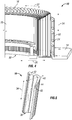
- the locator pins 70 and the mounting of the hub 26 may thus be designed in a variety of manners in accordance with different embodiments of the apparatus lO.One example of an element 16 is shown in perspective view in Fig. 5 .
- the element 16 has a cross-sectional profile that is V-shaped, and the element 16 is elongated in the longitudinal direction 34 so that it has a longer longitudinal length than a radial length.
- One or more tabs 36 can be included on the bottom of the element 16 for purposes of constraining movement of the element 16 on the base 14.
- a dividing line 43 is associated with the element 16 and this dividing line 43 marks the boundary between a radially outer half 42 and a radially inner half 44 of the element 16.
- a projection of the element 16 is located at the radially inner half 44.
- the radially inner half 44 is located closer to the central axis 18 in the radial direction 20 than the radially outer half 42.
- the halves 42, 44 are equal in length in the radial direction 20, but can have lengths that extend in the circumferential direction 22 that are different from one another, can have shapes that are different than one another, and can have thicknesses different from one another.
- the thicknesses of the halves 42, 44 is their lengths in the circumferential direction 22.
- the elements 16 can be aluminum extrusions that are subsequently machined. Alternatively, the elements 16 may be made out of other materials such as high modulus plastic.
- Fig. 6 shows the elements 16 of Fig. 5 positioned within the apparatus 10.
- Spokes 28 are also shown in Fig. 6 and are disposed between the elements 16 so that one spoke 28 is bordered on either side by a separate element 16.
- the number of spokes 28 may be the same as the number of elements 16.
- the spokes 28 have a V-shape that is similar to the profile shape of the elements 16, although the cross-sectional shapes of the spokes 28 and the elements 16 are not exact.
- the radial movement member 24 can move inwards in the radial direction 20 and engage the ends of the spokes 28.
- the spokes 28 will move inward, and as they engage the ends of the elements 16, the elements 16 will also move inwards in the radial direction 20 when the radial movement member 24 moves inwards.
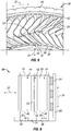
- Fig. 7 is a cross-sectional view that shows the interaction between the spokes 28, elements 16, hub 26, and radial movement member 24.
- a second element 72 and a second spoke 74 are identified for purposes of description.
- the elements 16, 72 and spokes 28, 74 are shown with the radial movement member 24 in an unactuated state so that the elements 16, 72 and spokes 28, 74 are not pushed inwards in the radial direction 20.
- the radial movement member 24 does not engage the elements 16, 72.
- the radial movement member 24 engages the spokes 28, 74 so that inward pushing of the spokes 28, 74 is translated to inward movement of the elements 16, 72. In some embodiments this is not the case and there is enough space between lips of spokes 28, 74 so that a portion of the second element 72 can extend beyond the lips of spokes 28, 74 in the radial direction 20 and engage the radial movement member 24. In these instances, the spokes 28, 74 do not make contact with the radial movement member 24, and force from the radial movement member 24 is transmitted directly into the elements 16, 72.
- the bladders 24 may engage the elements 16, and the spokes 28 may or may not also be engaged by the bladders 24.
- the spoke 16 can engage a portion of the radially outer half 42 of the element 16, but not all of the radially outer half 42.
- the spoke 28 has a central portion 54 that has a concave inner surface 56 and a convex outer surface 58.
- the concave inner surface 56 faces element 16 but does not engage element 16.
- the convex outer surface 58 engages adjacent second element 72.
- the portion of the element 16 that directly faces the concave inner surface 56 is not convex in shape, but instead has a flat shape and a space is between this flat surface and the concave inner surface 56.
- the radially inner half 44 of the element 16 is in engagement with the spoke 28 along a portion of its length, but not along its entire length. The length of engagement in the radial direction 20 between the spoke 28 and the element 16 may be greater in at the radially inner half 44 than at the radially outer half 42.
- the spoke 28 may have a longer length of engagement with the second element 72 at the radially inner half of the second element 72 than at the radially outer half of the second element 72.
- Surface engagement between the spokes 28, 74 and the elements 16, 72 along the radially inwards surfaces allows control of the position of the spokes 28, 74 as they are positioned with respect to the hub 26.
- the radially inner end of the spoke 28 includes a flange 52 that can engage the hub 26.
- the terminal end of the flange 52 may curve in the circumferential direction 22 so that it forms a concave surface that directly faces, and is complimentary to, the convex outer surface of the hub 26.
- the spoke 28 may define a notch 50 at a location outward from the flange 52 in the radial direction 20.
- the flange 52 and the notch 50 are at the radially inner halves of the spokes 28, 74.
- the elements 16, 72 have projections 48 at their radially inner halves 44, and the projection 48 nests within the notch 50.
- the projections 48 can be complimentary in shape to the notches 50 so that the notches 50 are completely filled by the projections 48 only when the spokes 28, 74 and elements 16, 72 have been moved radially inward to the farthest extent and contact has been made to sufficiently adhere the spokes 28, 74 to the hub 26.
- the elements 16, 72 do not engage the hub 26 when the radial movement member 24 is fully actuated.
- the projections 48 may be within the notches 50 at all times the spokes 28, 74 are between the elements 16, 72 at all distances in the radial direction 20 and regardless of whether the radial movement member 24 is or is not actuated.
- the radially inner terminal ends of the elements 16, 72 can simultaneously engage flanges 52 of two adjacent spokes 28, 74 when the radial movement member 24 is fully actuated, and in some instances when the radial movement member 24 is not actuated at all and when actuated at all in between levels of actuation.
- Adhesive 30 is located between the hub 26 and flange 52 and functions to hold the spokes 28, 74 to the hub 26.
- the flanges 52 can be variously shaped in other embodiments. In some instances, they can be triangular in shape and the notch 50 can be shaped differently than as shown or may not even be present in some embodiments.
- the elements 16 can be disposed within the notches 50 of the flanges 52 when the flanges 52 are triangular in shape, or the elements 16 may not be disposed within the notches 50 even if the notches are present.
- the spokes 28 are first molded and then inserted into the apparatus 10 so that each one is between two of the elements 16.
- the spokes 28 may be molded in individual molding cavities.
- the elements 16 can be located in the most outward position in the radial direction 20 before the elements 16 are inserted. Loading of the spokes 28 may be accomplished by an automated handling device that loads the spokes 28 from the top of the apparatus 10, that is in a direction towards the base 14. Alternatively, the spokes 28 may be manually loaded.
- the hub 26 may be independently formed and then inserted into the apparatus 10 and directly faces the spokes 28 when the spokes 28 are inserted and present.
- beads of adhesive 30 are applied to the hub 26 at locations that align with the flanges 52 on the spokes 28.
- a robot and adhesive dispenser may be used to place the adhesive 30 onto the hub 26.
- the adhesive 30 can be applied in linear strips around the circumference of the hub 26 that extend in the longitudinal direction 34.
- the adhesive 30 can separate the spokes 28 from the hub 26 so that they do not touch one another, or in some embodiments the spokes 28 and hub 26 may touch one another even with the presence of adhesive 30 used to bond these two components 26, 28 together.
- the radial movement member 24 can be actuated by inflating the membranes of the radial movement member 24 to cause the elements 16 to move inward in the radial direction 20. This actuation will also cause the spokes 28 to move inward in the radial direction 20 to achieve contact with the hub 26.
- the radial movement member 24 may maintain pressure on the spokes 28 to cause the flanges 52 of the spokes 28 to maintain engagement with the adhesive 30 and the hub 26 until the adhesive 30 is set. The force imparted onto the spokes 28 is transferred to the hub 26 and the hub 26 is held in place upon application of this force in the radial direction 20.
- the membranes of the radial movement member 24 may in some embodiments be capped off so that the apparatus 10 can be moved to an oven or other location. Once the adhesive 30 is set, the assembly of the hub 26 and spokes 28 can be removed, and the spokes 28 will be attached to the hub 26.
- the cross-sectional profiles of the elements 16 match up with some specific features of the spokes 28 and in some instances may be identically shaped and sized so as to receive portions of the spokes 28 or to be inserted into portions of the spokes 28.
- the cross-sectional profiles of the elements 16 may not completely match those of the spokes 28 along the entire radial lengths of the components 16, 28.
- the elements 16 can move in the radial direction 20 independently from one another, or may be linked to one another so that all of the elements 16 of the apparatus 10 move in concert with one another.
- the interaction of the spokes 28 and the elements 16 creates a precise self-aligned condition while maintaining uniform control of adhesive contact pressure between the spoke 28 and the hub 26 regardless of minor variations of the spokes 28 or hub 26.
- the elements 16 achieve a self-aligning capability of the spokes 28 when they are attached to the hub 26. Further, the application of force by the radial movement member 24 can be independent of the movement of the spokes 28 and hub 26 in the longitudinal direction 34.
- the elements 16 can align the spokes 28 and locate the spokes 28 onto a particular location of the hub 26 that is within plus or minus 0.2 millimeters in the desired circumferential direction 22.
- the elements 16 may also include stops 40 and other features built into their design that allow the spokes 28 to be located on the hub 26 to a precision of plus or minus 0.2 millimeters in the desired longitudinal direction 34.
- Encircling the elements 16 with the radial movement member 24 through the use of bladders causes the pressure applied onto the spokes 28 to be precisely controlled and adjustable.
- the application of uniform pressure to the spokes 28 achieves a consistent thickness of the adhesive 30 used to bond the spokes 28 to the hub 26.
- the arrangement of the elements 16 with the spokes 28 adjusts for spoke 28 to spoke flange 52 thickness variations.
- the elements 16 have a profile shape that is similar to, but not exact to that of the spokes 28 to result in a precisely aligned engagement to the hub 26 with uniform pressure applied thereto among all of the spokes 28.
- Fig. 8 shows an arc length segment of the non-pneumatic tire 12 in which the plurality of spokes 28 are engaged to and attached to the shear band 62 and the hub 26.
- the spokes 28 all feature a central portion 54 that has a convex outer surface 58 that faces a concave inner surface 56 of an adjacent spoke 28.
- the spokes 28 include flanges 52 that engage the hub 26, but may not engage flanges 52 of adjacent spokes 28. In some embodiments, the flanges 52 may in fact engage flanges 52 from adjacent spokes 28.
- the spokes 28 can be described as having a hairpin type spoke shape due to the central portion 54 that is V-shaped.
- the spokes 28 may be made from a thermoplastic material or from reinforced rubber.
- the various elements 16 may include one or more stops 40.
- the stops 40 are spaced from the base 14 in the longitudinal direction 34 and engage the bottom ends of the spokes 28 when the spokes 28 are inserted between the elements 16.
- the stops 40 function to space the spokes 28 from the base 14 to keep the spokes 28 located a distance from the base 14 when the spokes 28 are attached to the hub 26.
- the elements 16 are also sized so that they extend in the longitudinal direction 34 a greater distance than the spokes 28 so that the top of the spokes 28 are located below the tops of the elements 16 when the spokes 28 are located between the elements 16. When located between elements 16, the elements 16 extend beyond the spokes 28 in both directions in the longitudinal direction 34.
- the spokes 28 may have a length in the radial direction that is greater than that of the elements 16 so that the spokes 28 extend radially beyond both ends of the elements 16.
- the elements 16 include tabs 36 at their bottoms that are received within corresponding slots 38 of the base 14. The tabs 36 slide within the slots 38 and the slots 38 direct the radial and circumferential movement of the elements 16 and prevent the elements 16 from moving to unwanted locations during use of the apparatus 10.
- Fig. 10 is a bottom view of the apparatus 10 in which a series of coupling members 46 are attached to the elements 16.
- a portion of the base 14 may be located between the elements 16 and the coupling members 46.
- coupling member 46 is connected at two locations to element 16. In other embodiments the coupling member 46 may be connected to element 16 at but a single location.
- a couple member 46 is associated with, and connected to, each one of the elements 16 of the apparatus 10, and there may be the same number of elements 16 as there are coupling members 46.
- Each of the coupling member 46 can extend in the circumferential direction 22 beyond the element 16 to which it is attached, and the coupling members 46 can be nested within adjacent coupling members 46..
- this coupling member 46 may engage an adjacent coupling member 16 and cause the element 16 to which it is attached to likewise move.
- Coupling members 46 can be used on all of the elements 16 of the apparatus 10 so that all of the elements 16 move together inward and outward in the radial direction 20 when one of the elements 16 is moved inward or outward. In some instances, clearances may be present between the coupling members 46 so that they do not immediately cause movement when one of them moves.
Landscapes
- Engineering & Computer Science (AREA)
- Mechanical Engineering (AREA)
- Chemical & Material Sciences (AREA)
- Materials Engineering (AREA)
- Tyre Moulding (AREA)
- Tires In General (AREA)
Description
- The subject matter of the present invention relates to fixtures for the production of non-pneumatic tires. More particularly, the present application involves a fixture that includes elements that move radially inward to cause spokes within the fixture to be adhered onto an outer surface of a hub of a non-pneumatic tire.
-
US 103 669 relates to an apparatus for tire-setting comprising clamps, guides and a lever.CN 202 911 477 relates to a mounting apparatus for a bicycle component, in particular to a hand-operated mounting apparatus comprising a screw rod with a handle.US 4 108 233 relates to an assembling apparatus having a tire supporting frame, a powered actuator and a shoe assembly. - Non-pneumatic tires are those that do not require air.
- These tires instead feature a hub that is mounted onto a wheel of a vehicle, and a series of spokes that extend radially outward from the hub. The spokes can be attached to a shear band that includes tread of the tire. The spokes can be arranged and manufactured in a number of ways. Further, any number of spokes can be used in the design of non-pneumatic tires. However, when large numbers of spokes are used manufacturing problems arise. The large numbers of spokes require the spokes be positioned close to one another, and in these instances the spokes cannot be formed with the hub as part of a complete assembly. For a non-pneumatic tire to be constructed in a uniform manner, the circumferential and lateral precision of location of the spokes should be within 0.2 millimeters. Further, variations in spokes to spoke flange thicknesses exist in the manufacture of spokes, which also should be taken into account in any subsequent assembly process. Due to the various manufacturing challenges associated with the production of non-pneumatic tires, a mechanism for addressing and improving upon issues associated with their production would be beneficial.
- A full and enabling disclosure of the present invention, including the best mode thereof, directed to one of ordinary skill in the art, is set forth in the specification, which makes reference to the appended figures, in which:
-
Fig. 1 is a side view of a non-pneumatic tire. -
Fig. 2 is a perspective view of an apparatus for forming a non-pneumatic tire in accordance with one exemplary embodiment. -
Fig. 3 is a perspective view of a portion of the apparatus cut through a section of the apparatus. -
Fig. 4 is a perspective view of a portion of the apparatus cut through a section of the apparatus. -
Fig. 5 is a perspective view of an element. -
Fig. 6 is a top view of a portion of the apparatus. -
Fig. 7 is detailed top view of a portion of the apparatus that shows the interaction of elements, spokes, hub, and radial movement member. -
Fig. 8 is a side view of a portion of a non-pneumatic tire. -
Fig. 9 is a partial cross-sectional view of the apparatus. -
Fig. 10 is a bottom perspective view of a portion of the apparatus. - The use of identical or similar reference numerals in different figures denotes identical or similar features.
- Reference will now be made in detail to embodiments of the invention, one or more examples of which are illustrated in the drawings. Each example is provided by way of explanation of the invention, and not meant as a limitation of the invention. For example, features illustrated or described as part of one embodiment can be used with another embodiment to yield still a third embodiment. It is intended that the present invention include these and other modifications and variations.
- The present invention provides for an
apparatus 10 that is used in the construction of anon-pneumatic tire 12. Thenon-pneumatic tire 12 has a plurality ofspokes 28 that are connected to ahub 26. Theapparatus 10 includes a number ofelements 16 disposed about acentral axis 18 in which thespokes 28 are disposed betweensuccessive elements 16 in thecircumferential direction 22. Theelements 16 have a profile close to the profile of thespokes 28 but not the same as thespokes 28. Thehub 26 of thenon-pneumatic tire 12 is placed into theapparatus 10, and one or moreradial movement members 24 of theapparatus 10 are actuated in order to press theelements 16 and thespokes 28 inward in theradial direction 20. Thespokes 28 engage thehub 26 and adhesion is used to cause them to be connected to one another. The radially inward movement of theelements 16 and their profiled shape cause thespokes 28 to be precisely aligned and positioned on thehub 26 for a consistent, and known manufacture of thenon-pneumatic tire 12. -
Fig. 1 shows anon-pneumatic tire 12 in accordance with one exemplary embodiment. Thenon-pneumatic tire 12 has anaxis 60 at its center, and theradial direction 20 extends from theaxis 60. Tread 64 is located on the outer exterior of ashear band 62 and extends all the way around thenon-pneumatic tire 12 in thecircumferential direction 22. Theshear band 62 is located inward in theradial direction 20 from thetread 64 and likewise extends 360 degrees around theaxis 60 in thecircumferential direction 22. A series ofspokes 28 engage theshear band 62 and extend inward in theradial direction 20 from theshear band 62 to ahub 26 of thenon-pneumatic tire 12. Any number ofspokes 28 can be present, and their cross-sectional shape can be different form that shown. In some embodiments, from 64-80spokes 28 are present in thenon-pneumatic tire 12. Thehub 26 is located inward from thespokes 28 in theradial direction 20 and can be mounted onto a wheel of the vehicle. Thespokes 28 at the top of thenon-pneumatic tire 12 are in tension, and thespokes 28 at the bottom are in compression as thenon-pneumatic tire 12 rests on theground 66 and as thenon-pneumatic tire 12 turns in normal operation of the vehicle. - The
apparatus 10 is a mechanism that attaches thespokes 28 of thenon-pneumatic tire 12 to thehub 26. Thespokes 28 andhub 26 are pre-formed and are placed into theapparatus 10 at which time they are attached to one another.Fig. 2 shows one embodiment of theapparatus 10 that includes abase 14 that carries a series ofelements 16. Thebase 14 may be of any shape and is under theelements 16 and functions to support theelements 16. Thebase 14 is shown as being rectangular in shape and has an opencentral aperture 32. Thebase 14 may be in the shape of a ring in other versions, and need not have acentral aperture 32 in other versions of theapparatus 10. Theelements 16 are arranged in thecircumferential direction 22 completely around acentral axis 18 of theelements 16. Theelements 16 are spaced from thecentral axis 18 in theradial direction 20 and do not intersect thecentral axis 18. Theelements 16 can all be shaped identically with one another, or there may becertain elements 16 that are different fromother elements 16 with respect to their size or shape. Thecentral aperture 32 is positioned so that thecentral axis 18 extends through the center of thecentral aperture 32. Alongitudinal direction 34 of theapparatus 10 extends in the direction of thecentral axis 18 and can be parallel to thecentral axis 18. -
Fig. 3 is a cut-away view of a section of theapparatus 10 in a perspective orientation. Theelements 16 are situated in theradial direction 20 between a radiallyinward support member 70 and asupport member 68 of theapparatus 10. Thesupport member 68 extends upwards from thebase 14 in thelongitudinal direction 34 and houses theradial movement member 24. Theradial movement member 24 is composed of three bladders that are disposed within pockets of thesupport member 68 and are separate from one another. Theradial movement members 24 extend 360 degrees completely around thecentral axis 18 in thecircumferential direction 22. Air or other gas may be used to inflate the bladders of theradial movement member 24 and cause their expansion inward in theradial direction 20 from their positions shown inFig. 3 . The presence of thesupport member 68 prevents expansion of the bladders outward in theradial direction 20 from the positions shown inFig. 3 . The bladders of theradial movement member 24 engage thespokes 28 and/or theelements 16 and push thesemembers radial direction 20 towards thecentral axis 18. - The three bladders of the
radial movement member 24 can be simultaneously inflated at the same time, and at the same amount of pressure. Alternatively, they can be inflated at different times with different amounts of pressure as desired to prevent a binding condition of the guide surfaces or other reasons. In this regard, thebladder 24 that is closest to thetabs 36 in thelongitudinal direction 34 can be inflated first before the other twobladders 24, and a flow control system can be used to coordinate this sequential inflation. Subsequently, thebladder 24 that is in the middle in thelongitudinal direction 34 can be inflated, and then subsequently after that thebladder 24 that is farthest away from thetabs 36 in thelongitudinal direction 34 can be last inflated. Inflation of thebladders 24 in this sequential order allow thespokes 28 and theelements 16 to be urged against and to thehub 26 before significant pressure is applied by theother bladders 24 to prevent binding of the guiding surfaces. - Although three bladders are shown, it is to be understood that the
radial movement member 24 can have any number of bladders in other embodiments. For instance, 1, 2, from 4-6, or up to 10 bladders can be present. Also, each one of the bladders need not extend completely around thecentral axis 18 in thecircumferential direction 22 but can extend less than 360 degrees. Although shown as employing bladders to cause movement in the radial direction, theradial movement member 24 need not have bladders in other arrangements of theapparatus 10. For example, pneumatic or hydraulic cylinders of theradial movement member 24 could be used to effect inward radial motion in some arrangements. In other instances, theradial movement member 24 could employ ball screws, linkages, linear solenoids, or other mechanisms to achieve radial movement of theelements 16 andspokes 28. - The
apparatus 10 includes series of locator pins 70 that can be part of the base 14 that are disposed about thecentral axis 18. The locator pins 70 support thehub 26 that has a bearing surface that has a convex face that faces outward in theradial direction 20. This bearing surface can extend 360 degrees in thecircumferential direction 22 about thecentral axis 18 and can be attached at two different vertical locations to the locator pins 70, although any number of locator pins 70 may be implemented in other exemplary embodiments. Thehub 26 defines a boundary in theradial direction 20 in that theelements 16 and thespokes 28 cannot be moved radially inward of thehub 26 in theradial direction 20. -
Fig. 4 shows another variation of the embodiment of theapparatus 10 shown inFig. 3 . Here, the locator pins 70 extends in thelongitudinal direction 34 from the other portions of thebase 14. Thehub 26 is mounted to the locator pins 70 has a bearing surface with a convex outer surface. Thehub 26 is mounted at only one location of the base in thelongitudinal direction 34. The locator pins 70 and the mounting of thehub 26 may thus be designed in a variety of manners in accordance with different embodiments of the apparatus lO.One example of anelement 16 is shown in perspective view inFig. 5 . Theelement 16 has a cross-sectional profile that is V-shaped, and theelement 16 is elongated in thelongitudinal direction 34 so that it has a longer longitudinal length than a radial length. One ormore tabs 36 can be included on the bottom of theelement 16 for purposes of constraining movement of theelement 16 on thebase 14. A dividingline 43 is associated with theelement 16 and thisdividing line 43 marks the boundary between a radiallyouter half 42 and a radiallyinner half 44 of theelement 16. A projection of theelement 16 is located at the radiallyinner half 44. The radiallyinner half 44 is located closer to thecentral axis 18 in theradial direction 20 than the radiallyouter half 42. Thehalves radial direction 20, but can have lengths that extend in thecircumferential direction 22 that are different from one another, can have shapes that are different than one another, and can have thicknesses different from one another. The thicknesses of thehalves circumferential direction 22. Theelements 16 can be aluminum extrusions that are subsequently machined. Alternatively, theelements 16 may be made out of other materials such as high modulus plastic. -
Fig. 6 shows theelements 16 ofFig. 5 positioned within theapparatus 10.Spokes 28 are also shown inFig. 6 and are disposed between theelements 16 so that one spoke 28 is bordered on either side by aseparate element 16. The number ofspokes 28 may be the same as the number ofelements 16. Thespokes 28 have a V-shape that is similar to the profile shape of theelements 16, although the cross-sectional shapes of thespokes 28 and theelements 16 are not exact. Theradial movement member 24 can move inwards in theradial direction 20 and engage the ends of thespokes 28. Thespokes 28 will move inward, and as they engage the ends of theelements 16, theelements 16 will also move inwards in theradial direction 20 when theradial movement member 24 moves inwards. There is a greater amount of space between thespokes 28 and theelements 16 in at the radiallyouter halves 42 than at the radiallyinner halves 44. This is because as theelements 16 move closer to thecentral axis 18, less space is available at the radially outer portions of theelements 16 andspokes 28 and these components become tighter with one another. Thehub 26 is now shown inFig. 6 for purposes of clarity, but would be located between the radiallyinward support member 70 and the terminal ends ofspokes 28. -
Fig. 7 is a cross-sectional view that shows the interaction between thespokes 28,elements 16,hub 26, andradial movement member 24. Asecond element 72 and asecond spoke 74 are identified for purposes of description. Theelements spokes radial movement member 24 in an unactuated state so that theelements spokes radial direction 20. There is a larger amount of space between the adjacent radiallyouter halves 42 of theelements inner halves 44 of theelements radial movement member 24 does not engage theelements radial movement member 24 engages thespokes spokes elements spokes second element 72 can extend beyond the lips ofspokes radial direction 20 and engage theradial movement member 24. In these instances, thespokes radial movement member 24, and force from theradial movement member 24 is transmitted directly into theelements Fig. 4 thebladders 24 may engage theelements 16, and thespokes 28 may or may not also be engaged by thebladders 24. Thespoke 16 can engage a portion of the radiallyouter half 42 of theelement 16, but not all of the radiallyouter half 42. - The
spoke 28 has acentral portion 54 that has a concaveinner surface 56 and a convexouter surface 58. The concaveinner surface 56 faceselement 16 but does not engageelement 16. The convexouter surface 58 engages adjacentsecond element 72. The portion of theelement 16 that directly faces the concaveinner surface 56 is not convex in shape, but instead has a flat shape and a space is between this flat surface and the concaveinner surface 56. The radiallyinner half 44 of theelement 16 is in engagement with thespoke 28 along a portion of its length, but not along its entire length. The length of engagement in theradial direction 20 between thespoke 28 and theelement 16 may be greater in at the radiallyinner half 44 than at the radiallyouter half 42. In a similar manner, thespoke 28 may have a longer length of engagement with thesecond element 72 at the radially inner half of thesecond element 72 than at the radially outer half of thesecond element 72. Surface engagement between thespokes elements spokes hub 26. There is relief between the profile of theelements spokes spokes - The radially inner end of the
spoke 28 includes aflange 52 that can engage thehub 26. The terminal end of theflange 52 may curve in thecircumferential direction 22 so that it forms a concave surface that directly faces, and is complimentary to, the convex outer surface of thehub 26. Thespoke 28 may define anotch 50 at a location outward from theflange 52 in theradial direction 20. Theflange 52 and thenotch 50 are at the radially inner halves of thespokes elements projections 48 at their radiallyinner halves 44, and theprojection 48 nests within thenotch 50. Theprojections 48 can be complimentary in shape to thenotches 50 so that thenotches 50 are completely filled by theprojections 48 only when thespokes elements spokes hub 26. Theelements hub 26 when theradial movement member 24 is fully actuated. Theprojections 48 may be within thenotches 50 at all times thespokes elements radial direction 20 and regardless of whether theradial movement member 24 is or is not actuated. The radially inner terminal ends of theelements flanges 52 of twoadjacent spokes radial movement member 24 is fully actuated, and in some instances when theradial movement member 24 is not actuated at all and when actuated at all in between levels of actuation.Adhesive 30 is located between thehub 26 andflange 52 and functions to hold thespokes hub 26. Theflanges 52 can be variously shaped in other embodiments. In some instances, they can be triangular in shape and thenotch 50 can be shaped differently than as shown or may not even be present in some embodiments. Theelements 16 can be disposed within thenotches 50 of theflanges 52 when theflanges 52 are triangular in shape, or theelements 16 may not be disposed within thenotches 50 even if the notches are present. - To assemble the
non-pneumatic tire 12, thespokes 28 are first molded and then inserted into theapparatus 10 so that each one is between two of theelements 16. Thespokes 28 may be molded in individual molding cavities. Theelements 16 can be located in the most outward position in theradial direction 20 before theelements 16 are inserted. Loading of thespokes 28 may be accomplished by an automated handling device that loads thespokes 28 from the top of theapparatus 10, that is in a direction towards thebase 14. Alternatively, thespokes 28 may be manually loaded. Thehub 26 may be independently formed and then inserted into theapparatus 10 and directly faces thespokes 28 when thespokes 28 are inserted and present. Prior to insertion into theapparatus 10, beads of adhesive 30 are applied to thehub 26 at locations that align with theflanges 52 on thespokes 28. A robot and adhesive dispenser may be used to place the adhesive 30 onto thehub 26. The adhesive 30 can be applied in linear strips around the circumference of thehub 26 that extend in thelongitudinal direction 34. The adhesive 30 can separate thespokes 28 from thehub 26 so that they do not touch one another, or in some embodiments thespokes 28 andhub 26 may touch one another even with the presence of adhesive 30 used to bond these twocomponents - Next, the
radial movement member 24 can be actuated by inflating the membranes of theradial movement member 24 to cause theelements 16 to move inward in theradial direction 20. This actuation will also cause thespokes 28 to move inward in theradial direction 20 to achieve contact with thehub 26. Theradial movement member 24 may maintain pressure on thespokes 28 to cause theflanges 52 of thespokes 28 to maintain engagement with the adhesive 30 and thehub 26 until the adhesive 30 is set. The force imparted onto thespokes 28 is transferred to thehub 26 and thehub 26 is held in place upon application of this force in theradial direction 20. The membranes of theradial movement member 24 may in some embodiments be capped off so that theapparatus 10 can be moved to an oven or other location. Once the adhesive 30 is set, the assembly of thehub 26 andspokes 28 can be removed, and thespokes 28 will be attached to thehub 26. - The cross-sectional profiles of the
elements 16 match up with some specific features of thespokes 28 and in some instances may be identically shaped and sized so as to receive portions of thespokes 28 or to be inserted into portions of thespokes 28. The cross-sectional profiles of theelements 16 may not completely match those of thespokes 28 along the entire radial lengths of thecomponents elements 16 can move in theradial direction 20 independently from one another, or may be linked to one another so that all of theelements 16 of theapparatus 10 move in concert with one another. As theradial movement member 24 is actuated, the interaction of thespokes 28 and theelements 16 creates a precise self-aligned condition while maintaining uniform control of adhesive contact pressure between thespoke 28 and thehub 26 regardless of minor variations of thespokes 28 orhub 26. Theelements 16 achieve a self-aligning capability of thespokes 28 when they are attached to thehub 26. Further, the application of force by theradial movement member 24 can be independent of the movement of thespokes 28 andhub 26 in thelongitudinal direction 34. - The
elements 16 can align thespokes 28 and locate thespokes 28 onto a particular location of thehub 26 that is within plus or minus 0.2 millimeters in the desiredcircumferential direction 22. Theelements 16 may also includestops 40 and other features built into their design that allow thespokes 28 to be located on thehub 26 to a precision of plus or minus 0.2 millimeters in the desiredlongitudinal direction 34. Encircling theelements 16 with theradial movement member 24 through the use of bladders causes the pressure applied onto thespokes 28 to be precisely controlled and adjustable. The application of uniform pressure to thespokes 28 achieves a consistent thickness of the adhesive 30 used to bond thespokes 28 to thehub 26. The arrangement of theelements 16 with thespokes 28 adjusts forspoke 28 tospoke flange 52 thickness variations. Theelements 16 have a profile shape that is similar to, but not exact to that of thespokes 28 to result in a precisely aligned engagement to thehub 26 with uniform pressure applied thereto among all of thespokes 28. -
Fig. 8 shows an arc length segment of thenon-pneumatic tire 12 in which the plurality ofspokes 28 are engaged to and attached to theshear band 62 and thehub 26. Thespokes 28 all feature acentral portion 54 that has a convexouter surface 58 that faces a concaveinner surface 56 of anadjacent spoke 28. Thespokes 28 includeflanges 52 that engage thehub 26, but may not engageflanges 52 ofadjacent spokes 28. In some embodiments, theflanges 52 may in fact engageflanges 52 fromadjacent spokes 28. Thespokes 28 can be described as having a hairpin type spoke shape due to thecentral portion 54 that is V-shaped. Thespokes 28 may be made from a thermoplastic material or from reinforced rubber. - With reference to
Fig. 9 , thevarious elements 16 may include one or more stops 40. The stops 40 are spaced from the base 14 in thelongitudinal direction 34 and engage the bottom ends of thespokes 28 when thespokes 28 are inserted between theelements 16. The stops 40 function to space thespokes 28 from the base 14 to keep thespokes 28 located a distance from the base 14 when thespokes 28 are attached to thehub 26. Theelements 16 are also sized so that they extend in the longitudinal direction 34 a greater distance than thespokes 28 so that the top of thespokes 28 are located below the tops of theelements 16 when thespokes 28 are located between theelements 16. When located betweenelements 16, theelements 16 extend beyond thespokes 28 in both directions in thelongitudinal direction 34. Thespokes 28 may have a length in the radial direction that is greater than that of theelements 16 so that thespokes 28 extend radially beyond both ends of theelements 16. Theelements 16 includetabs 36 at their bottoms that are received within correspondingslots 38 of thebase 14. Thetabs 36 slide within theslots 38 and theslots 38 direct the radial and circumferential movement of theelements 16 and prevent theelements 16 from moving to unwanted locations during use of theapparatus 10. -
Fig. 10 is a bottom view of theapparatus 10 in which a series ofcoupling members 46 are attached to theelements 16. A portion of the base 14 may be located between theelements 16 and thecoupling members 46. As shown inFig. 10 ,coupling member 46 is connected at two locations toelement 16. In other embodiments thecoupling member 46 may be connected toelement 16 at but a single location. Acouple member 46 is associated with, and connected to, each one of theelements 16 of theapparatus 10, and there may be the same number ofelements 16 as there are couplingmembers 46. Each of thecoupling member 46 can extend in thecircumferential direction 22 beyond theelement 16 to which it is attached, and thecoupling members 46 can be nested withinadjacent coupling members 46.. As one of theelements 16 moves in theradial direction 20 due to movement of the attachedelement 16, thiscoupling member 46 may engage anadjacent coupling member 16 and cause theelement 16 to which it is attached to likewise move. Couplingmembers 46 can be used on all of theelements 16 of theapparatus 10 so that all of theelements 16 move together inward and outward in theradial direction 20 when one of theelements 16 is moved inward or outward. In some instances, clearances may be present between thecoupling members 46 so that they do not immediately cause movement when one of them moves. By linking all of theelements 16 to one another via thecoupling members 46, a move uniform and distributed movement of theelements 16 results so that variances in dimensions and force application uniformity by theradial movement member 24 can be accounted for in the build process.
Claims (15)
- An apparatus (10) for assembling a non-pneumatic tire (12), the apparatus (10) comprising:a base (14);a plurality of elements (16, 72) that move relative to the base (14), wherein the plurality of elements (16, 72) have a central axis (18), wherein the elements (16, 72) move in a radial direction (20) towards and away from the central axis (18), wherein the elements (16, 72) are disposed in a circumferential direction (22) around the central axis (18); anda radial movement member (24);the non-pneumatic tire (12) havinga hub (26); anda plurality of spokes (28, 74),wherein each one of the spokes (28, 74) can be disposed between adjacent ones of the elements (16, 72), characterised in that the elements (16, 72) and the spokes (28, 74) can be moved inwards in the radial direction (20) by the radial movement member (24) towards the central axis (18) so that the spokes (28, 74) can be moved in the radial direction (20) towards the hub (26), wherein adhesive (30) can engage the spokes (28, 74) and the hub (26) at an attachment location of the spokes (28, 74) and the hub (26).
- The apparatus (10) as set forth in claim 1, wherein the base (14) is rectangular in shape, and wherein the base (14) has a central aperture (32) through which the central axis (18) extends.
- The apparatus (10) as set forth in claim 1 or 2, wherein the radial movement member (24) comprising a plurality of pneumatic bladders that are disposed circumferentially around the central axis (18), wherein in use the pneumatic bladders are located outward from the elements (16, 72) and the spokes (28, 74) in the radial direction (20).
- The apparatus (10) as set forth in claim 3, wherein three pneumatic bladders are present, wherein a longitudinal direction (34) is parallel to and extends in the direction of the central axis (18), wherein the three pneumatic bladders are spaced from one another in the longitudinal direction (34) and are not in engagement with one another.
- The apparatus (10) as set forth in claim 4, wherein three pneumatic bladders are present and inflate sequentially relative to one another such that one of the pneumatic bladders first begins inflation followed by one of the pneumatic bladders that is located between the other two pneumatic bladders in the longitudinal direction (34), wherein the final one of the three pneumatic bladders begins inflation after the one of the pneumatic bladders located between the other two pneumatic bladders in the longitudinal direction (34) begins inflation.
- The apparatus (10) as set forth in any one of claims 3-5, wherein inflation of the pneumatic bladders causes the elements (16, 72) and the spokes (28, 74) to be moved inward in the radial direction (20), wherein the pneumatic bladders engage both the elements (16, 72) and the spokes (28, 74).
- The apparatus (10) as set forth in any one of claims 3-5, wherein inflation of the pneumatic bladders causes the pneumatic bladders to engage the elements (16, 72), wherein inflation of the pneumatic bladders does not cause engagement of the pneumatic bladders and the spokes (28, 74), wherein the elements (16, 72) extend outward in the radial direction (20) beyond the spokes (28, 74).
- The apparatus (10) as set forth in any one of claims 1-7, wherein the elements (16, 72) have tabs (36) on lower ends of the elements (16, 72) that are disposed within slots (38) of the base (14), wherein the elements (16, 72) have stops (40) that are engaged by the spokes (28, 74) and limit movement of the spokes (28, 74) towards the base (14).
- The apparatus (10) as set forth in any one of claims 1-8, wherein the elements (16, 72) and the spokes (28, 74) have V-shaped cross-sectional profiles, wherein the elements (16, 72) have larger cross-sectional profiles than the spokes (28, 74), wherein a shape of the cross-sectional profiles of the elements (16, 72) is different than a shape of the cross-sectional profiles of the spokes (28, 74).
- The apparatus (10) as set forth in any one of claims 1-9, wherein the spokes (28, 74) can be spaced from elements (16, 72) adjacent the spokes (28, 74) in the circumferential direction (22) a greater amount at a radially outer half (42) of the elements (16, 72) than at a radially inner half (44) of the elements (16, 72), wherein the radially outer half (42) of the elements (16, 72) is located farther from the central axis (18) in the radial direction (20) than the radially inner half (44) of the elements (16, 72).
- The apparatus (10) as set forth in any one of claims 1-10, further comprising a plurality of coupling members (46) that are V-shaped and are nested within one another, wherein the number of coupling members (46) present is the same as the number of elements (16, 72) present, wherein each one of the coupling members (46) is attached to one of the elements (16, 72), wherein the coupling members (46) are located at bottoms of the elements (16, 72), wherein radial movement of the elements (16, 72) causes the coupling members (46) to move in the radial direction (20) and engage one another to in turn cause other elements (16, 72) to move in the radial direction (20).
- The apparatus (10) as set forth in any one of claims 1-11, wherein the adhesive (30) is located on the hub (26) before the spokes (28, 74) are moved into engagement with the adhesive (30).
- The apparatus (10) as set forth in any one of claims 1-12, wherein the elements (16, 72) have a projection (48) at inner radial ends of the elements (16, 72) that nest within complimentary notches (50) of the spokes (28, 74), wherein the elements (16, 72) are free from engagement with the hub (26) when the elements (16, 72) are moved into a position closest to the central axis (18) in the radial direction (20).
- The apparatus (10) as set forth in any one of claims 1-13, wherein each one of the elements (16, 72) can simultaneously engage the flanges (52) on the inner radial ends of the spokes (28, 74) of two adjacent spokes (28, 74).
- The apparatus (10) as set forth in any one of claims 1-14, wherein in use of the apparatus (10) the spokes (28, 74) are closer to adjacent elements (16, 72) and are farther from adjacent elements (16, 72) upon extension of the spokes (28, 74) and the elements (16, 72) from inner radial ends of the spokes (28, 74) and the elements (16, 72) outward in the radial direction (20) to midpoints of the elements (16, 72) in the radial direction (20).
Applications Claiming Priority (2)
| Application Number | Priority Date | Filing Date | Title |
|---|---|---|---|
| PCT/US2016/069402 WO2018125188A1 (en) | 2016-12-30 | 2016-12-30 | Fixture for spoke to hub attachment for a non-pneumatic tire |
| PCT/US2017/068634 WO2018125959A1 (en) | 2016-12-30 | 2017-12-28 | Fixture for spoke to hub attachment for a non-pneumatic tire |
Publications (2)
| Publication Number | Publication Date |
|---|---|
| EP3562684A1 EP3562684A1 (en) | 2019-11-06 |
| EP3562684B1 true EP3562684B1 (en) | 2021-11-03 |
Family
ID=57868359
Family Applications (1)
| Application Number | Title | Priority Date | Filing Date |
|---|---|---|---|
| EP17830093.5A Active EP3562684B1 (en) | 2016-12-30 | 2017-12-28 | Apparatus for assembling a non- pneumatic tire |
Country Status (4)
| Country | Link |
|---|---|
| US (1) | US11597234B2 (en) |
| EP (1) | EP3562684B1 (en) |
| CN (1) | CN110114227B (en) |
| WO (2) | WO2018125188A1 (en) |
Families Citing this family (5)
| Publication number | Priority date | Publication date | Assignee | Title |
|---|---|---|---|---|
| WO2018125193A1 (en) * | 2016-12-30 | 2018-07-05 | Compagnie General Des Etablissements Michelin | Fixture for spoke to shear band attachment for a non-pneumatic tire |
| US12043070B2 (en) | 2018-12-28 | 2024-07-23 | Bridgestone Americas Tire Operations, Llc | Flexible metallic web elements for non-pneumatic tire |
| CN114953850B (en) * | 2021-02-22 | 2023-10-27 | Htr有限公司 | Variable compliance metal wheel with torque measuring device |
| KR20230020849A (en) * | 2021-08-04 | 2023-02-13 | 현대자동차주식회사 | Wheel for driving and driving unit including the same |
| FR3129104B1 (en) * | 2021-11-15 | 2023-11-10 | Michelin & Cie | DEVICE FOR ASSEMBLYING THE SPOKES OF A WHEEL TIRE BY MEANS OF PUSHERS WHICH ARE ACTUATED AND ELASTICALLY SUSPENDED BY LEVERS |
Family Cites Families (13)
| Publication number | Priority date | Publication date | Assignee | Title |
|---|---|---|---|---|
| US103669A (en) * | 1870-05-31 | Improvement in tire-setting- machines | ||
| US39275A (en) * | 1863-07-21 | Machine for compressing carriage-wheels | ||
| US4108233A (en) * | 1977-03-30 | 1978-08-22 | Caterpillar Tractor Co. | Tire and center support assembling apparatus |
| JPH0796708A (en) * | 1993-08-04 | 1995-04-11 | Hakuhou Kogyo Kk | Industrial rubber wheel and manufacturing method thereof |
| EP1186444A2 (en) * | 2000-09-07 | 2002-03-13 | The Goodyear Tire & Rubber Company | Improved rim for a compliant wheel assembly |
| JP5401192B2 (en) * | 2009-07-22 | 2014-01-29 | 株式会社ブリヂストン | Non-pneumatic tire manufacturing apparatus and non-pneumatic tire manufacturing method |
| US9387637B2 (en) * | 2012-09-07 | 2016-07-12 | Caterpillar Inc. | Systems and methods for forming non-pneumatic tires |
| CN202911477U (en) * | 2012-11-02 | 2013-05-01 | 广州市晨旭科技发展有限公司 | Hand-operated mounting instrument for non-pneumatic tire |
| WO2017116384A1 (en) * | 2015-12-28 | 2017-07-06 | Campagnie Generale Des Etablissements Michelin | Method of forming non-pneumatic tire using support structure deformation |
| WO2017116454A1 (en) * | 2015-12-31 | 2017-07-06 | Compagnie Generale Des Etablissements Michelin | Non-pneumatic wheel |
| CN105539001A (en) * | 2016-01-28 | 2016-05-04 | 中信戴卡股份有限公司 | Safety protection wheel |
| CN105774408A (en) * | 2016-04-29 | 2016-07-20 | 江苏理工学院 | Spoke-inflatable elastic wheel |
| WO2018125195A1 (en) * | 2016-12-30 | 2018-07-05 | Compagnie Generale Des Etablissements Michelin | Fixture for spoke to shear band attachment for a non-pneumatic tire with spoke pre-compression |
-
2016
- 2016-12-30 WO PCT/US2016/069402 patent/WO2018125188A1/en not_active Ceased
-
2017
- 2017-12-28 EP EP17830093.5A patent/EP3562684B1/en active Active
- 2017-12-28 CN CN201780081035.4A patent/CN110114227B/en active Active
- 2017-12-28 US US16/464,285 patent/US11597234B2/en active Active
- 2017-12-28 WO PCT/US2017/068634 patent/WO2018125959A1/en not_active Ceased
Non-Patent Citations (1)
| Title |
|---|
| None * |
Also Published As
| Publication number | Publication date |
|---|---|
| WO2018125188A1 (en) | 2018-07-05 |
| US11597234B2 (en) | 2023-03-07 |
| WO2018125959A1 (en) | 2018-07-05 |
| CN110114227A (en) | 2019-08-09 |
| US20200276863A1 (en) | 2020-09-03 |
| CN110114227B (en) | 2022-06-21 |
| EP3562684A1 (en) | 2019-11-06 |
Similar Documents
| Publication | Publication Date | Title |
|---|---|---|
| EP3562684B1 (en) | Apparatus for assembling a non- pneumatic tire | |
| EP3397466B1 (en) | Method of forming non-pneumatic tire using support structure deformation | |
| EP3713753B1 (en) | Method and apparatus for forming a non-pneumatic tire carcass | |
| EP3397465B1 (en) | Method of forming non-pneumatic tire including pressure application between an intermediate section and an outer shear band ring | |
| EP3562686B1 (en) | Fixture for spoke to shear band attachment for a non-pneumatic tire with spoke pre-compression | |
| US20240399793A1 (en) | Flexible metallic web elements for non-pneumatic tire | |
| US8678059B2 (en) | Modifiable element for shaping a raw tire blank | |
| RS58992B1 (en) | Method and drum for manufacturing a tyre, in particular a run-flat tyre | |
| US10479036B2 (en) | Tire building drum with a turn-up mechanism | |
| WO2018126028A1 (en) | Static fixture for spoke to hub attachment for a non-pneumatic tire | |
| EP3562685B1 (en) | Apparatus for assembling a non-pneumatic tire | |
| EP3717223B1 (en) | Drum for the application of semi-finished products within tyres, and process for the application of semi-finished products within tyres | |
| KR102231501B1 (en) | Vulcanizing apparatus for vehicle tire | |
| CN117597229A (en) | Cured mold assembly for non-pneumatic tires and method of making |
Legal Events
| Date | Code | Title | Description |
|---|---|---|---|
| STAA | Information on the status of an ep patent application or granted ep patent |
Free format text: STATUS: UNKNOWN |
|
| STAA | Information on the status of an ep patent application or granted ep patent |
Free format text: STATUS: THE INTERNATIONAL PUBLICATION HAS BEEN MADE |
|
| PUAI | Public reference made under article 153(3) epc to a published international application that has entered the european phase |
Free format text: ORIGINAL CODE: 0009012 |
|
| STAA | Information on the status of an ep patent application or granted ep patent |
Free format text: STATUS: REQUEST FOR EXAMINATION WAS MADE |
|
| 17P | Request for examination filed |
Effective date: 20190528 |
|
| AK | Designated contracting states |
Kind code of ref document: A1 Designated state(s): AL AT BE BG CH CY CZ DE DK EE ES FI FR GB GR HR HU IE IS IT LI LT LU LV MC MK MT NL NO PL PT RO RS SE SI SK SM TR |
|
| AX | Request for extension of the european patent |
Extension state: BA ME |
|
| DAV | Request for validation of the european patent (deleted) | ||
| DAX | Request for extension of the european patent (deleted) | ||
| GRAP | Despatch of communication of intention to grant a patent |
Free format text: ORIGINAL CODE: EPIDOSNIGR1 |
|
| STAA | Information on the status of an ep patent application or granted ep patent |
Free format text: STATUS: GRANT OF PATENT IS INTENDED |
|
| INTG | Intention to grant announced |
Effective date: 20200929 |
|
| GRAS | Grant fee paid |
Free format text: ORIGINAL CODE: EPIDOSNIGR3 |
|
| GRAJ | Information related to disapproval of communication of intention to grant by the applicant or resumption of examination proceedings by the epo deleted |
Free format text: ORIGINAL CODE: EPIDOSDIGR1 |
|
| GRAL | Information related to payment of fee for publishing/printing deleted |
Free format text: ORIGINAL CODE: EPIDOSDIGR3 |
|
| STAA | Information on the status of an ep patent application or granted ep patent |
Free format text: STATUS: REQUEST FOR EXAMINATION WAS MADE |
|
| INTC | Intention to grant announced (deleted) | ||
| GRAP | Despatch of communication of intention to grant a patent |
Free format text: ORIGINAL CODE: EPIDOSNIGR1 |
|
| STAA | Information on the status of an ep patent application or granted ep patent |
Free format text: STATUS: GRANT OF PATENT IS INTENDED |
|
| INTG | Intention to grant announced |
Effective date: 20210526 |
|
| GRAA | (expected) grant |
Free format text: ORIGINAL CODE: 0009210 |
|
| STAA | Information on the status of an ep patent application or granted ep patent |
Free format text: STATUS: THE PATENT HAS BEEN GRANTED |
|
| AK | Designated contracting states |
Kind code of ref document: B1 Designated state(s): AL AT BE BG CH CY CZ DE DK EE ES FI FR GB GR HR HU IE IS IT LI LT LU LV MC MK MT NL NO PL PT RO RS SE SI SK SM TR |
|
| REG | Reference to a national code |
Ref country code: GB Ref legal event code: FG4D |
|
| REG | Reference to a national code |
Ref country code: AT Ref legal event code: REF Ref document number: 1443646 Country of ref document: AT Kind code of ref document: T Effective date: 20211115 Ref country code: CH Ref legal event code: EP |
|
| REG | Reference to a national code |
Ref country code: DE Ref legal event code: R096 Ref document number: 602017048830 Country of ref document: DE |
|
| REG | Reference to a national code |
Ref country code: IE Ref legal event code: FG4D |
|
| REG | Reference to a national code |
Ref country code: LT Ref legal event code: MG9D |
|
| REG | Reference to a national code |
Ref country code: NL Ref legal event code: MP Effective date: 20211103 |
|
| REG | Reference to a national code |
Ref country code: AT Ref legal event code: MK05 Ref document number: 1443646 Country of ref document: AT Kind code of ref document: T Effective date: 20211103 |
|
| PG25 | Lapsed in a contracting state [announced via postgrant information from national office to epo] |
Ref country code: RS Free format text: LAPSE BECAUSE OF FAILURE TO SUBMIT A TRANSLATION OF THE DESCRIPTION OR TO PAY THE FEE WITHIN THE PRESCRIBED TIME-LIMIT Effective date: 20211103 Ref country code: LT Free format text: LAPSE BECAUSE OF FAILURE TO SUBMIT A TRANSLATION OF THE DESCRIPTION OR TO PAY THE FEE WITHIN THE PRESCRIBED TIME-LIMIT Effective date: 20211103 Ref country code: FI Free format text: LAPSE BECAUSE OF FAILURE TO SUBMIT A TRANSLATION OF THE DESCRIPTION OR TO PAY THE FEE WITHIN THE PRESCRIBED TIME-LIMIT Effective date: 20211103 Ref country code: BG Free format text: LAPSE BECAUSE OF FAILURE TO SUBMIT A TRANSLATION OF THE DESCRIPTION OR TO PAY THE FEE WITHIN THE PRESCRIBED TIME-LIMIT Effective date: 20220203 Ref country code: AT Free format text: LAPSE BECAUSE OF FAILURE TO SUBMIT A TRANSLATION OF THE DESCRIPTION OR TO PAY THE FEE WITHIN THE PRESCRIBED TIME-LIMIT Effective date: 20211103 |
|
| PG25 | Lapsed in a contracting state [announced via postgrant information from national office to epo] |
Ref country code: IS Free format text: LAPSE BECAUSE OF FAILURE TO SUBMIT A TRANSLATION OF THE DESCRIPTION OR TO PAY THE FEE WITHIN THE PRESCRIBED TIME-LIMIT Effective date: 20220303 Ref country code: SE Free format text: LAPSE BECAUSE OF FAILURE TO SUBMIT A TRANSLATION OF THE DESCRIPTION OR TO PAY THE FEE WITHIN THE PRESCRIBED TIME-LIMIT Effective date: 20211103 Ref country code: PT Free format text: LAPSE BECAUSE OF FAILURE TO SUBMIT A TRANSLATION OF THE DESCRIPTION OR TO PAY THE FEE WITHIN THE PRESCRIBED TIME-LIMIT Effective date: 20220303 Ref country code: PL Free format text: LAPSE BECAUSE OF FAILURE TO SUBMIT A TRANSLATION OF THE DESCRIPTION OR TO PAY THE FEE WITHIN THE PRESCRIBED TIME-LIMIT Effective date: 20211103 Ref country code: NO Free format text: LAPSE BECAUSE OF FAILURE TO SUBMIT A TRANSLATION OF THE DESCRIPTION OR TO PAY THE FEE WITHIN THE PRESCRIBED TIME-LIMIT Effective date: 20220203 Ref country code: NL Free format text: LAPSE BECAUSE OF FAILURE TO SUBMIT A TRANSLATION OF THE DESCRIPTION OR TO PAY THE FEE WITHIN THE PRESCRIBED TIME-LIMIT Effective date: 20211103 Ref country code: LV Free format text: LAPSE BECAUSE OF FAILURE TO SUBMIT A TRANSLATION OF THE DESCRIPTION OR TO PAY THE FEE WITHIN THE PRESCRIBED TIME-LIMIT Effective date: 20211103 Ref country code: HR Free format text: LAPSE BECAUSE OF FAILURE TO SUBMIT A TRANSLATION OF THE DESCRIPTION OR TO PAY THE FEE WITHIN THE PRESCRIBED TIME-LIMIT Effective date: 20211103 Ref country code: GR Free format text: LAPSE BECAUSE OF FAILURE TO SUBMIT A TRANSLATION OF THE DESCRIPTION OR TO PAY THE FEE WITHIN THE PRESCRIBED TIME-LIMIT Effective date: 20220204 Ref country code: ES Free format text: LAPSE BECAUSE OF FAILURE TO SUBMIT A TRANSLATION OF THE DESCRIPTION OR TO PAY THE FEE WITHIN THE PRESCRIBED TIME-LIMIT Effective date: 20211103 |
|
| PG25 | Lapsed in a contracting state [announced via postgrant information from national office to epo] |
Ref country code: SM Free format text: LAPSE BECAUSE OF FAILURE TO SUBMIT A TRANSLATION OF THE DESCRIPTION OR TO PAY THE FEE WITHIN THE PRESCRIBED TIME-LIMIT Effective date: 20211103 Ref country code: SK Free format text: LAPSE BECAUSE OF FAILURE TO SUBMIT A TRANSLATION OF THE DESCRIPTION OR TO PAY THE FEE WITHIN THE PRESCRIBED TIME-LIMIT Effective date: 20211103 Ref country code: RO Free format text: LAPSE BECAUSE OF FAILURE TO SUBMIT A TRANSLATION OF THE DESCRIPTION OR TO PAY THE FEE WITHIN THE PRESCRIBED TIME-LIMIT Effective date: 20211103 Ref country code: EE Free format text: LAPSE BECAUSE OF FAILURE TO SUBMIT A TRANSLATION OF THE DESCRIPTION OR TO PAY THE FEE WITHIN THE PRESCRIBED TIME-LIMIT Effective date: 20211103 Ref country code: DK Free format text: LAPSE BECAUSE OF FAILURE TO SUBMIT A TRANSLATION OF THE DESCRIPTION OR TO PAY THE FEE WITHIN THE PRESCRIBED TIME-LIMIT Effective date: 20211103 Ref country code: CZ Free format text: LAPSE BECAUSE OF FAILURE TO SUBMIT A TRANSLATION OF THE DESCRIPTION OR TO PAY THE FEE WITHIN THE PRESCRIBED TIME-LIMIT Effective date: 20211103 |
|
| REG | Reference to a national code |
Ref country code: CH Ref legal event code: PL |
|
| REG | Reference to a national code |
Ref country code: DE Ref legal event code: R097 Ref document number: 602017048830 Country of ref document: DE |
|
| PG25 | Lapsed in a contracting state [announced via postgrant information from national office to epo] |
Ref country code: MC Free format text: LAPSE BECAUSE OF FAILURE TO SUBMIT A TRANSLATION OF THE DESCRIPTION OR TO PAY THE FEE WITHIN THE PRESCRIBED TIME-LIMIT Effective date: 20211103 |
|
| PLBE | No opposition filed within time limit |
Free format text: ORIGINAL CODE: 0009261 |
|
| STAA | Information on the status of an ep patent application or granted ep patent |
Free format text: STATUS: NO OPPOSITION FILED WITHIN TIME LIMIT |
|
| REG | Reference to a national code |
Ref country code: BE Ref legal event code: MM Effective date: 20211231 |
|
| 26N | No opposition filed |
Effective date: 20220804 |
|
| GBPC | Gb: european patent ceased through non-payment of renewal fee |
Effective date: 20220203 |
|
| PG25 | Lapsed in a contracting state [announced via postgrant information from national office to epo] |
Ref country code: LU Free format text: LAPSE BECAUSE OF NON-PAYMENT OF DUE FEES Effective date: 20211228 Ref country code: IE Free format text: LAPSE BECAUSE OF NON-PAYMENT OF DUE FEES Effective date: 20211228 Ref country code: AL Free format text: LAPSE BECAUSE OF FAILURE TO SUBMIT A TRANSLATION OF THE DESCRIPTION OR TO PAY THE FEE WITHIN THE PRESCRIBED TIME-LIMIT Effective date: 20211103 |
|
| PG25 | Lapsed in a contracting state [announced via postgrant information from national office to epo] |
Ref country code: SI Free format text: LAPSE BECAUSE OF FAILURE TO SUBMIT A TRANSLATION OF THE DESCRIPTION OR TO PAY THE FEE WITHIN THE PRESCRIBED TIME-LIMIT Effective date: 20211103 Ref country code: BE Free format text: LAPSE BECAUSE OF NON-PAYMENT OF DUE FEES Effective date: 20211231 |
|
| PG25 | Lapsed in a contracting state [announced via postgrant information from national office to epo] |
Ref country code: LI Free format text: LAPSE BECAUSE OF NON-PAYMENT OF DUE FEES Effective date: 20211231 Ref country code: CH Free format text: LAPSE BECAUSE OF NON-PAYMENT OF DUE FEES Effective date: 20211231 |
|
| PG25 | Lapsed in a contracting state [announced via postgrant information from national office to epo] |
Ref country code: GB Free format text: LAPSE BECAUSE OF NON-PAYMENT OF DUE FEES Effective date: 20220203 |
|
| PG25 | Lapsed in a contracting state [announced via postgrant information from national office to epo] |
Ref country code: IT Free format text: LAPSE BECAUSE OF FAILURE TO SUBMIT A TRANSLATION OF THE DESCRIPTION OR TO PAY THE FEE WITHIN THE PRESCRIBED TIME-LIMIT Effective date: 20211103 |
|
| PG25 | Lapsed in a contracting state [announced via postgrant information from national office to epo] |
Ref country code: CY Free format text: LAPSE BECAUSE OF FAILURE TO SUBMIT A TRANSLATION OF THE DESCRIPTION OR TO PAY THE FEE WITHIN THE PRESCRIBED TIME-LIMIT Effective date: 20211103 |
|
| PG25 | Lapsed in a contracting state [announced via postgrant information from national office to epo] |
Ref country code: HU Free format text: LAPSE BECAUSE OF FAILURE TO SUBMIT A TRANSLATION OF THE DESCRIPTION OR TO PAY THE FEE WITHIN THE PRESCRIBED TIME-LIMIT; INVALID AB INITIO Effective date: 20171228 |
|
| PG25 | Lapsed in a contracting state [announced via postgrant information from national office to epo] |
Ref country code: MK Free format text: LAPSE BECAUSE OF FAILURE TO SUBMIT A TRANSLATION OF THE DESCRIPTION OR TO PAY THE FEE WITHIN THE PRESCRIBED TIME-LIMIT Effective date: 20211103 |
|
| PG25 | Lapsed in a contracting state [announced via postgrant information from national office to epo] |
Ref country code: MT Free format text: LAPSE BECAUSE OF FAILURE TO SUBMIT A TRANSLATION OF THE DESCRIPTION OR TO PAY THE FEE WITHIN THE PRESCRIBED TIME-LIMIT Effective date: 20211103 |
|
| PG25 | Lapsed in a contracting state [announced via postgrant information from national office to epo] |
Ref country code: TR Free format text: LAPSE BECAUSE OF FAILURE TO SUBMIT A TRANSLATION OF THE DESCRIPTION OR TO PAY THE FEE WITHIN THE PRESCRIBED TIME-LIMIT Effective date: 20211103 |
|
| PGFP | Annual fee paid to national office [announced via postgrant information from national office to epo] |
Ref country code: DE Payment date: 20251211 Year of fee payment: 9 |
|
| PGFP | Annual fee paid to national office [announced via postgrant information from national office to epo] |
Ref country code: FR Payment date: 20251229 Year of fee payment: 9 |