EP3562626B1 - Sous-ensemble d'exosquelette et structure d'exosquelette incluant un tel sous-ensemble - Google Patents
Sous-ensemble d'exosquelette et structure d'exosquelette incluant un tel sous-ensemble Download PDFInfo
- Publication number
- EP3562626B1 EP3562626B1 EP17822714.6A EP17822714A EP3562626B1 EP 3562626 B1 EP3562626 B1 EP 3562626B1 EP 17822714 A EP17822714 A EP 17822714A EP 3562626 B1 EP3562626 B1 EP 3562626B1
- Authority
- EP
- European Patent Office
- Prior art keywords
- user
- rotation
- foot
- sub
- leg
- Prior art date
- Legal status (The legal status is an assumption and is not a legal conclusion. Google has not performed a legal analysis and makes no representation as to the accuracy of the status listed.)
- Active
Links
Images



Classifications
-
- B—PERFORMING OPERATIONS; TRANSPORTING
- B25—HAND TOOLS; PORTABLE POWER-DRIVEN TOOLS; MANIPULATORS
- B25J—MANIPULATORS; CHAMBERS PROVIDED WITH MANIPULATION DEVICES
- B25J9/00—Program-controlled manipulators
- B25J9/0006—Exoskeletons, i.e. resembling a human figure
-
- A—HUMAN NECESSITIES
- A61—MEDICAL OR VETERINARY SCIENCE; HYGIENE
- A61H—PHYSICAL THERAPY APPARATUS, e.g. DEVICES FOR LOCATING OR STIMULATING REFLEX POINTS IN THE BODY; ARTIFICIAL RESPIRATION; MASSAGE; BATHING DEVICES FOR SPECIAL THERAPEUTIC OR HYGIENIC PURPOSES OR SPECIFIC PARTS OF THE BODY
- A61H3/00—Appliances for aiding patients or disabled persons to walk about
-
- B—PERFORMING OPERATIONS; TRANSPORTING
- B25—HAND TOOLS; PORTABLE POWER-DRIVEN TOOLS; MANIPULATORS
- B25J—MANIPULATORS; CHAMBERS PROVIDED WITH MANIPULATION DEVICES
- B25J9/00—Program-controlled manipulators
- B25J9/0009—Constructional details, e.g. manipulator supports, bases
-
- A—HUMAN NECESSITIES
- A61—MEDICAL OR VETERINARY SCIENCE; HYGIENE
- A61H—PHYSICAL THERAPY APPARATUS, e.g. DEVICES FOR LOCATING OR STIMULATING REFLEX POINTS IN THE BODY; ARTIFICIAL RESPIRATION; MASSAGE; BATHING DEVICES FOR SPECIAL THERAPEUTIC OR HYGIENIC PURPOSES OR SPECIFIC PARTS OF THE BODY
- A61H3/00—Appliances for aiding patients or disabled persons to walk about
- A61H2003/007—Appliances for aiding patients or disabled persons to walk about secured to the patient, e.g. with belts
-
- A—HUMAN NECESSITIES
- A61—MEDICAL OR VETERINARY SCIENCE; HYGIENE
- A61H—PHYSICAL THERAPY APPARATUS, e.g. DEVICES FOR LOCATING OR STIMULATING REFLEX POINTS IN THE BODY; ARTIFICIAL RESPIRATION; MASSAGE; BATHING DEVICES FOR SPECIAL THERAPEUTIC OR HYGIENIC PURPOSES OR SPECIFIC PARTS OF THE BODY
- A61H2201/00—Characteristics of apparatus not provided for in the preceding codes
- A61H2201/01—Constructive details
- A61H2201/0107—Constructive details modular
-
- A—HUMAN NECESSITIES
- A61—MEDICAL OR VETERINARY SCIENCE; HYGIENE
- A61H—PHYSICAL THERAPY APPARATUS, e.g. DEVICES FOR LOCATING OR STIMULATING REFLEX POINTS IN THE BODY; ARTIFICIAL RESPIRATION; MASSAGE; BATHING DEVICES FOR SPECIAL THERAPEUTIC OR HYGIENIC PURPOSES OR SPECIFIC PARTS OF THE BODY
- A61H2201/00—Characteristics of apparatus not provided for in the preceding codes
- A61H2201/16—Physical interface with patient
- A61H2201/1602—Physical interface with patient kind of interface, e.g. head rest, knee support or lumbar support
- A61H2201/164—Feet or leg, e.g. pedal
- A61H2201/1642—Holding means therefor
-
- A—HUMAN NECESSITIES
- A61—MEDICAL OR VETERINARY SCIENCE; HYGIENE
- A61H—PHYSICAL THERAPY APPARATUS, e.g. DEVICES FOR LOCATING OR STIMULATING REFLEX POINTS IN THE BODY; ARTIFICIAL RESPIRATION; MASSAGE; BATHING DEVICES FOR SPECIAL THERAPEUTIC OR HYGIENIC PURPOSES OR SPECIFIC PARTS OF THE BODY
- A61H2201/00—Characteristics of apparatus not provided for in the preceding codes
- A61H2201/16—Physical interface with patient
- A61H2201/1602—Physical interface with patient kind of interface, e.g. head rest, knee support or lumbar support
- A61H2201/165—Wearable interfaces
-
- A—HUMAN NECESSITIES
- A61—MEDICAL OR VETERINARY SCIENCE; HYGIENE
- A61H—PHYSICAL THERAPY APPARATUS, e.g. DEVICES FOR LOCATING OR STIMULATING REFLEX POINTS IN THE BODY; ARTIFICIAL RESPIRATION; MASSAGE; BATHING DEVICES FOR SPECIAL THERAPEUTIC OR HYGIENIC PURPOSES OR SPECIFIC PARTS OF THE BODY
- A61H2201/00—Characteristics of apparatus not provided for in the preceding codes
- A61H2201/16—Physical interface with patient
- A61H2201/1657—Movement of interface, i.e. force application means
- A61H2201/1671—Movement of interface, i.e. force application means rotational
- A61H2201/1673—Multidimensional rotation
-
- A—HUMAN NECESSITIES
- A61—MEDICAL OR VETERINARY SCIENCE; HYGIENE
- A61H—PHYSICAL THERAPY APPARATUS, e.g. DEVICES FOR LOCATING OR STIMULATING REFLEX POINTS IN THE BODY; ARTIFICIAL RESPIRATION; MASSAGE; BATHING DEVICES FOR SPECIAL THERAPEUTIC OR HYGIENIC PURPOSES OR SPECIFIC PARTS OF THE BODY
- A61H2201/00—Characteristics of apparatus not provided for in the preceding codes
- A61H2201/16—Physical interface with patient
- A61H2201/1657—Movement of interface, i.e. force application means
- A61H2201/1676—Pivoting
Definitions
- the invention relates to an exoskeleton sub-assembly and an exoskeleton structure including such a sub-assembly.
- the invention relates to an exoskeleton sub-assembly according to the preamble of claim 1.
- Exercise assistance exoskeletons are mechanical structures positioned parallel to the human skeleton and which improve the physical capacities of the human body.
- exoskeletons There are different types of exoskeletons, the shape and structure of which depend on the tasks to be performed by the user.
- the two main types of exoskeleton are those intended to assist the user's movements on the one hand, and those intended to increase the user's strength capacities, on the other hand.
- exoskeletal structures In order to relieve the user, there are known exoskeletal structures in which part of the mass of the exoskeleton is transferred to the ground via plates placed under the user's feet and connected to the rest of the structure.
- this type of structure does not make it possible to provide support on the ground in all walking phases and / or on all types of ground, in particular when the user is walking on sloping or uneven ground.
- the document EP2 942 044 A2 shows an exoskeleton subassembly according to the preamble of claim 1.
- An aim of the invention is to provide a solution for relieving the user of the loads he is carrying, whether it is the load generated by the structure of the exoskeleton itself, by external elements which can be associated with the structure of the exoskeleton (for example a backpack) or the actual weight of the user if the latter is carried by the structure, while having better comfort and better mobility.
- the invention is based on the observation that, in the human body, the internal / external rotational movement of the foot is not due to the sole contribution of the ankle, but also to the contributions of other joints, in particular those of the knee. and hip.
- the tibial segment which extends along the user's tibia is formed in two parts, the first articulation being arranged between these two parts and allowing internal rotational movement. of the user's foot.
- This arrangement of the first joint between the user's knee and ankle allows the exoskeleton sub-assembly to adapt to the internal / external rotational movements of the user's foot, thereby improving comfort and fit. mobility of the latter.
- the third articulation allows the exoskeleton sub-assembly to adapt to the eversion / inversion movements of the user's foot, thus increasing the degrees of freedom allowed and also helping to improve the comfort and mobility of the user. this last.
- the invention also relates to an exoskeleton structure comprising at least one exoskeleton subassembly as defined above.
- the exoskeleton structure 1 shown comprises a ventral belt 2, a first mechanical assembly 3 and a second mechanical assembly 4.
- the lap belt 2 is suitable for surrounding the lower trunk of the user.
- the first mechanical assembly 3 is suitable for being connected to a first lower limb of the user (right lower limb) to assist the movement of the first lower limb when walking or running.
- the second mechanical assembly 4 is suitable for being connected to a second lower limb of the user (lower left limb) to assist the movement of the second lower limb when walking or of the race.
- the first mechanical assembly 3 and the second mechanical assembly 4 are each connected to the lap belt 2.
- the first mechanical assembly 3 comprises a first thigh part 31, a first leg part 32 and a first foot part 33.
- the first thigh portion 31 comprises a first femoral segment 311 intended to extend along a first thigh (right thigh) of the user and fixing straps 312 adapted to surround the first thigh of the user to fix the femoral segment 311 at the first thigh.
- the first leg portion 32 includes a first tibial segment 321 intended to extend along a first leg (right leg) of the user and attachment straps 322 adapted to surround the first leg of the user to secure. the tibial segment 321 at the first leg.
- the first part of the foot 33 is fixed to a first shoe 51 of the user, for example to a sole 511 of the first shoe 51.
- the first part of the foot 33 can be fixed to the sole 511 by means of screws or by means of screws. 'other suitable means of attachment.
- the first femoral segment 311 includes a first end 313 connected to the lap belt 2 through a first hip joint 34 and a second end 314 connected to the first tibial segment 321 through a first knee joint 35.
- the first tibial segment 321 includes a first end 323 connected to the first femoral segment 311 by the first knee joint 35 and a second end 324 connected to the first part of the foot 33 by means of a first ankle joint 36.
- the first tibial segment 321 is formed in two pieces.
- the first tibial segment 321 comprises a first part 325 (or upper part), a second part 326 (or lower part) and a first articulation 327 connecting the second part 326 to the first part 325.
- the first part 325 is connected to the first part. thigh part 31 via the knee joint 35.
- the second part 326 is connected to the first part of the foot 33 via the ankle joint 36.
- the first articulation 327 connecting the second part 326 to the first part 325 is arranged to allow rotation of the second part 326 relative to the first part 325 caused by an internal / external rotational movement of the user's right foot relative to the right leg.
- the second mechanical assembly 4 is symmetrical to the first mechanical assembly 3.
- the second mechanical assembly 4 also comprises a second thigh part 41, a second leg part 42 and a second foot part 43.
- the second thigh portion 41 comprises a second femoral segment 411 intended to extend along a second thigh (left thigh) of the user and fixing straps 412 suitable for surrounding the second thigh of the user for fixing the femoral segment 411 at the second thigh.
- the second leg portion 42 includes a second tibial segment 421 intended to extend along a second leg (left leg) of the user and attachment straps 422 adapted to surround the second leg of the user to secure. the tibial segment 421 to the second leg.
- the second part of the foot 43 is fixed to a second shoe 52 of the user, for example to a sole 521 of the shoe 52.
- the second part of the foot 43 can be fixed to the sole 521 by means of screws.
- the second femoral segment 411 includes a first end 413 connected to the lap belt 2 via a second hip joint 44 and a second end 414 connected to the second tibial segment 421 via a second knee joint 45.
- the second tibial segment 421 includes a first end 423 connected to the second femoral segment 411 by the second knee joint 45 and a second end 424 connected to the second part of the foot 43 through a second ankle joint 46.
- the second tibial segment 421 is also formed in two pieces.
- the second tibial segment 421 comprises a first part 425 (or upper part), a second part 426 (or lower part) and a first articulation 427 connecting the second part 426 to the first part 425.
- the first part 425 is connected to the second thigh part 41 via the knee joint 45.
- the second part 426 is connected to the second foot part 43 via the ankle joint 46.
- the first joint 427 connecting the second part 426 to the first part 425 is arranged to allow a rotation of the second part 426 relative to the first part 425 caused by an internal / external rotational movement of the user's left foot with respect to the left leg.
- the hip joints 34, 44 and the knee joints 35, 45 may include actuators to assist the user during a flexion or extension movement of the hip or the knee.
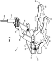
- the figures 2 and 3 show in more detail a first exoskeleton sub-assembly 30 comprising the first leg part 32, the first foot part 33 and the first ankle joint 36, according to one embodiment of the invention.
- the second exoskeleton 40 sub-assembly comprising the second leg part 42, the second foot part 43 and the second ankle joint 46 is symmetrical to the first exoskeleton sub-assembly 30.
- the second sub-assembly the exoskeleton assembly 40 is therefore formed of elements identical or similar to those of the first exoskeleton sub-assembly 30, and functions in the same way as the first exoskeleton sub-assembly 30.
- the first leg part 33 comprises an attachment part 331, an articulation 332 and an intermediate part 333.
- the attachment piece 331 is intended to be attached to the user's shoe 51. More precisely, the attachment part 331 is designed to be fixed to the sole 511 of the boot 51.
- the part attachment 331 comprises two arms 335 and 336 arranged to extend respectively on either side of the shoe 51, along the sole 511 of the shoe 51.
- Each arm 335, 336 has two fixing holes 337, 338 in which fasteners (for example screws) can be inserted to fasten the arm 335, 336 to the sole 511.
- the fastening holes 337 define first fastening points through which passes a first transverse fold line P1 of the sole 511 relative to the attachment piece 331.
- the orifices 338 define second attachment points through which a second transverse fold line P2 of the sole 511 relative to the attachment piece 331. Because of this from the arrangement of the fixing points, the arms 335 and 336 allow bending of the sole 511 of the boot 51 along two fold lines P1 and P2 which are not parallel to each other.
- the attachment points corresponding to the attachment holes 337 are arranged so that the first fold line P1 extends under the user's heel.
- the attachment points corresponding to the attachment holes 338 are arranged so that the second fold line P2 extends below the joints of the toes of the user.
- each arm 335, 336 has projecting portions 307 and 308, extending below the fixing holes 337 and 338, each portion 307, 308 being able to come into contact with the ground in order to limit crushing of the sole 511 at the location of the attachment points of the arms 335 and 336 to the sole 511.
- the intermediate part 333 is connected to the attachment part 331 by means of the articulation 332.
- the articulation 332 is disposed at the rear of the user's shoe 51, behind the heel.
- the articulation 332 allows rotation of the attachment piece 331 relative to the intermediate piece 332 caused by an eversion / inversion movement of the foot relative to the user's leg.
- the articulation 332 allows a rotation of the attachment part 331 relative to the intermediate part 333 about an axis of rotation X parallel to an axis of eversion / inversion of the foot of the user, when the tibial part 32 is fixed to the leg and the foot part 33 is fixed to the user's foot.
- the articulation 332 may consist of a connecting assembly such as that described in French patent application no. 1657295 filed July 28, 2016.
- the intermediate part 333 has the general shape of a U.
- the intermediate part 333 comprises in particular two intermediate arms 375, 376 extending respectively on either side of the user's shoe 51.
- the second part 326 of the tibial segment 32 also has a general U-shape.
- the second part 326 comprises in particular two connecting arms 385 and 386, each connecting arm 385, 386 being respectively connected to one of the intermediate arms 375, 376 of the intermediate piece 333 through an ankle joint 36.
- the ankle joints 36 allow rotation of the intermediate piece 333 relative to the second piece 326 of the tibial segment 32 caused by a flexion / extension movement of the foot relative to the leg.
- the ankle joints 36 allow rotation of the intermediate piece 333 relative to the second piece 326 about a Y axis of rotation parallel to a flexion / extension axis of the user's foot, when the tibial part 32 is attached to the leg and that the foot portion 33 is attached to the shoe 51 of the user.
- Each ankle joint 36 may consist of a connecting assembly such as the one described in French patent application no. 1657295 filed July 28, 2016.
- each arm 385, 386 of the second part 326 may itself be formed in two parts, one part of which is sliding relative to the other part so as to allow adjustment of the height and depth of the 'articulation 327 with respect to the ankle joint 36. This also makes it possible to quickly separate the part of the foot 33 attached to the shoe 51 from the rest of the exoskeleton structure 1. The user can thus keep his shoes 51 and 52 , after removing the rest of the exoskeleton structure.
- the second part 326 of the tibial segment 32 is connected to the first part 325 of the tibial segment 32 through the articulation 327.
- the articulation 327 is arranged in front of the user's leg when the tibial part 32 is fixed. to the leg and that the part of the foot 33 is fixed to the shoe 51 of the user.
- the articulation 327 allows rotation of the second part 326 relative to the first part 325 about an axis of rotation Z which is parallel to an axis of internal / external rotation of the user's foot (substantially vertical direction when the (user is in an upright position).
- the axis of rotation Z of the joint 327 is orthogonal to the axis of rotation Y of the ankle joints 36.
- the joint 327 can be oriented so that the axis of rotation Z is concurrent with the joint.
- the sub-assembly 30 illustrated on figures 2 and 3 thus allows rotation of the user's right foot relative to the right leg according to three degrees of freedom.
- the arrangement of the X, Y and Z axes of rotation allows the exoskeleton sub-assembly to adapt to the movements of the user's foot, thereby improving the comfort and mobility of the latter.
- sub-assembly 40 allows rotation of the user's left foot relative to the left leg according to three degrees of freedom.
- the arrangement of the pivots 36 on each side of the user's ankle makes it possible to balance the load which is applied to the pivot 332 located behind the user's heel.
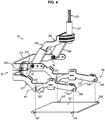
- the figure 4 schematically shows a variant of the attachment part 331.
- the sole 511 of the shoe 51 is provided with a fixing plate 541.
- the fixing plate 541 can be embedded in the sole of the shoe 51.
- the fixing plate 541 has fixing pins 547, 548. extending from the side edges of the plate 541 and projecting on either side of the sole.
- Each arm 335, 336 of the attachment piece 331 has two attachment slots 347, 348 in which attachment pins 547, 548 can be inserted vertically to secure the arm 335, 336 to the sole 511.
- Each fixing slot 347 and 348 can be provided with a latching device making it possible to lock the fixing pins 547, 548 in the fixing slots 347, 348.
- the figures 5A to 5C schematically illustrate an example of a snap-fastening device, with hook and spring, making it possible to lock a fixing pin 547 in a fixing slot 347.
- the fixing slots 347, 348 and the fixing pins 547, 548, as well as the possible snap-fastening devices, allow the part of the foot 33 to be quickly hooked and released from the shoe 51.
Landscapes
- Engineering & Computer Science (AREA)
- Robotics (AREA)
- Mechanical Engineering (AREA)
- Health & Medical Sciences (AREA)
- Epidemiology (AREA)
- Pain & Pain Management (AREA)
- Physical Education & Sports Medicine (AREA)
- Rehabilitation Therapy (AREA)
- Life Sciences & Earth Sciences (AREA)
- Animal Behavior & Ethology (AREA)
- General Health & Medical Sciences (AREA)
- Public Health (AREA)
- Veterinary Medicine (AREA)
- Rehabilitation Tools (AREA)
- Footwear And Its Accessory, Manufacturing Method And Apparatuses (AREA)
- Manipulator (AREA)
Description
- L'invention concerne un sous-ensemble d'exosquelette et une structure d'exosquelette incluant un tel sous-ensemble.
- Plus particulièrement, l'invention concerne un sous-ensemble d'exosquelette selon le préambule de la revendication 1.
- Les exosquelettes d'assistance à l'effort sont des structures mécaniques positionnées en parallèle du squelette humain et qui permettent d'améliorer les capacités physiques du corps humain.
- Il existe différents types d'exosquelettes, dont la forme et la structure dépendent des tâches à accomplir par l'utilisateur. Les deux principaux types d'exosquelettes sont ceux destinés à l'assistance aux mouvements de l'utilisateur d'une part, et ceux destinés à la démultiplication des capacités de force de l'utilisateur, d'autre part.
- Dans le cas des exosquelettes destinés à l'assistance aux mouvements de l'utilisateur, l'utilisateur doit généralement transporter la structure de l'exosquelette puisque celle-ci est disposée sur son corps, ce qui a pour conséquence de limiter la liberté de mouvement de l'utilisateur et de générer une charge supplémentaire et de la fatigue associée.
- Afin de soulager l'utilisateur, on connait des structures d'exosquelette dans lesquelles une partie de la masse de l'exosquelette est transférée au sol via des plaques disposées sous les pieds de l'utilisateur et reliées au reste de la structure.
- Dans ces structures, les pieds de l'utilisateur ne sont pas en contact avec le sol, ce qui rend la structure peu confortable.
- De plus, du fait de la présence des plaques, la mobilité de l'utilisateur est nécessairement réduite. Par ailleurs, afin d'assurer un transfert de la masse de l'exosquelette vers le sol, ces structures n'autorisent généralement pas pleinement une rotation du pied de l'utilisateur, et en particulier un mouvement de rotation interne/externe du pied de l'utilisateur par rapport à sa jambe.
- Cela a pour conséquence que ce type de structure ne permet pas de procurer un appui sur le sol dans toutes les phases de marche et/ou sur tous types de sols, notamment lorsque l'utilisateur marche sur un sol en pente ou irrégulier.
- Le document
EP2 942 044 A2 montre un sous-ensemble d'exosquelette selon le préambule de la revendication 1. - Un but de l'invention est de proposer une solution pour soulager l'utilisateur des charges qu'il porte, que ce soit la charge générée par la structure de l'exosquelette en elle-même, par des éléments externes pouvant être associés à la structure de l'exosquelette (par exemple un sac à dos) ou le poids même de l'utilisateur si celui-ci est porté par la structure, tout en présentant un meilleur confort et une meilleure mobilité.
- Ce but est atteint dans le cadre de la présente invention grâce à un sous-ensemble d'exosquelette selon la revendication 1.
- L'invention est basée sur le constat que, dans le corps humain, le mouvement de rotation interne/externe du pied n'est pas dû à la seule contribution de la cheville, mais également aux contributions d'autres articulations, notamment celles du genou et de la hanche.
- Ainsi, dans le sous-ensemble d'exosquelette proposé, le segment tibial qui s'étend le long du tibia de l'utilisateur est formé en deux pièces, la première articulation étant disposée entre ces deux pièces et autorisant le mouvement de rotation interne/externe du pied de l'utilisateur.
- Cette disposition de la première articulation entre le genou et la cheville de l'utilisateur permet au sous-ensemble d'exosquelette de s'adapter aux mouvements de rotation interne/externe du pied de l'utilisateur, améliorant de ce fait le confort et la mobilité de ce dernier.
- Par ailleurs, la troisième articulation permet au sous-ensemble d'exosquelette de s'adapter aux mouvements d'éversion/inversion du pied de l'utilisateur, augmentant ainsi les degrés de liberté autorisés et contribuant également à améliorer le confort et la mobilité de ce dernier.
- Le sous-ensemble peut en outre présenter les caractéristiques suivantes :
- le sous-ensemble comprend une deuxième articulation reliant la deuxième pièce à la partie de pied, la deuxième articulation autorisant une rotation de la partie de pied par rapport à la partie de jambe causée par un mouvement de flexion/extension du pied de l'utilisateur,
- la première articulation autorise une rotation de la deuxième pièce par rapport à la première pièce autour d'un premier axe de rotation, et la deuxième articulation autorise une rotation de la partie de pied par rapport à la deuxième pièce autour d'un deuxième axe de rotation, et le premier axe de rotation et le deuxième axe de rotation sont orthogonaux entre eux,
- la pièce d'attache comprend deux bras de fixation pour fixer la pièce d'attache sur la chaussure, les bras de fixation autorisant une flexion de la semelle de la chaussure selon deux lignes de pliures non parallèles,
- la pièce d'attache présente des fentes dans lesquelles peuvent être insérées des pions de fixation pour fixer la pièce d'attache sur la chaussure.
- L'invention se rapporte également à une structure d'exosquelette comprenant au moins un sous-ensemble d'exosquelette tel que défini précédemment.
- D'autres caractéristiques et avantages ressortiront encore de la description qui suit, laquelle est purement illustrative et non limitative et doit être lue en regard des figures annexées, parmi lesquelles :
- la
figure 1 représente de manière schématique, en vue de face, un utilisateur équipé d'une structure d'exosquelette conforme à un mode de réalisation de l'invention, - la
figure 2 représente de manière schématique, en perspective, un sous-ensemble de la structure d'exosquelette de lafigure 1 , - la
figure 3 représente de manière schématique, en vue de côté, un sous-ensemble de la structure d'exosquelette de lafigure 1 , - la
figure 4 représente de manière schématique, en perspective, une variante de la pièce d'attache du sous-ensemble de la structure d'exosquelette de lafigure 1 , - les
figures 5A à 5C représentent de manière schématique un dispositif d'encliquetage permettant de verrouiller la pièce d'attache sur une chaussure. - Sur la
figure 1 , la structure d'exosquelette 1 représentée comprend une ceinture ventrale 2, un premier ensemble mécanique 3 et un deuxième ensemble mécanique 4. - La ceinture ventrale 2 est propre à entourer le bas du tronc de l'utilisateur. Le premier ensemble mécanique 3 est propre à être relié à un premier membre inférieur de l'utilisateur (membre inférieur droit) pour assister le mouvement du premier membre inférieur lors de la marche ou de la course. Le deuxième ensemble mécanique 4 est propre à être relié à un deuxième membre inférieur de l'utilisateur (membre inférieur gauche) pour assister le mouvement du deuxième membre inférieur lors de la marche ou de la course. Le premier ensemble mécanique 3 et le deuxième ensemble mécanique 4 sont raccordés chacun à la ceinture ventrale 2.
- Le premier ensemble mécanique 3 comprend une première partie de cuisse 31, une première partie de jambe 32 et une première partie de pied 33.
- La première partie de cuisse 31 comprend un premier segment fémoral 311 prévu pour s'étendre le long d'une première cuisse (cuisse droite) de l'utilisateur et des sangles de fixation 312 propres à entourer la première cuisse de l'utilisateur pour fixer le segment fémoral 311 à la première cuisse.
- La première partie de jambe 32 comprend un premier segment tibial 321 prévu pour s'étendre le long d'une première jambe (jambe droite) de l'utilisateur et des sangles de fixation 322 propres à entourer la première jambe de l'utilisateur pour fixer le segment tibial 321 à la première jambe.
- La première partie de pied 33 est fixée à une première chaussure 51 de l'utilisateur, par exemple à une semelle 511 de la première chaussure 51. La première partie de pied 33 peut être fixée à la semelle 511 au moyen de vis ou par d'autres moyens de fixation appropriés.
- Le premier segment fémoral 311 comprend une première extrémité 313 raccordée à la ceinture ventrale 2 par le biais d'une première articulation de hanche 34 et une deuxième extrémité 314 raccordée au premier segment tibial 321 par le biais d'une première articulation de genou 35.
- Le premier segment tibial 321 comprend une première extrémité 323 raccordée au premier segment fémoral 311 par la première articulation de genou 35 et une deuxième extrémité 324 raccordée à la première partie de pied 33 par le biais d'une première articulation de cheville 36.
- Comme cela est visible sur la
figure 1 , le premier segment tibial 321 est formé en deux pièces. Le premier segment tibial 321 comprend une première pièce 325 (ou pièce supérieure), une deuxième pièce 326 (ou pièce inférieure) et une première articulation 327 reliant la deuxième pièce 326 à la première pièce 325. La première pièce 325 est reliée à la première partie de cuisse 31 via l'articulation de genou 35. La deuxième pièce 326 est reliée à la première partie de pied 33 via l'articulation de cheville 36. La première articulation 327 reliant la deuxième pièce 326 à la première pièce 325 est agencée pour autoriser une rotation de la deuxième pièce 326 par rapport à la première pièce 325 causée par un mouvement de rotation interne/externe du pied droit de l'utilisateur par rapport à la jambe droite. - Le deuxième ensemble mécanique 4 est symétrique du premier ensemble mécanique 3.
- Ainsi, le deuxième ensemble mécanique 4 comprend également une deuxième partie de cuisse 41, une deuxième partie de jambe 42 et une deuxième partie de pied 43.
- La deuxième partie de cuisse 41 comprend un deuxième segment fémoral 411 prévu pour s'étendre le long d'une deuxième cuisse (cuisse gauche) de l'utilisateur et des sangles de fixation 412 propres à entourer la deuxième cuisse de l'utilisateur pour fixer le segment fémoral 411 à la deuxième cuisse.
- La deuxième partie de jambe 42 comprend un deuxième segment tibial 421 prévu pour s'étendre le long d'une deuxième jambe (jambe gauche) de l'utilisateur et des sangles de fixation 422 propres à entourer la deuxième jambe de l'utilisateur pour fixer le segment tibial 421 à la deuxième jambe.
- La deuxième partie de pied 43 est fixée à une deuxième chaussure 52 de l'utilisateur, par exemple à une semelle 521 de la chaussure 52. La deuxième pièce de pied 43 peut être fixée à la semelle 521 au moyen de vis.
- Le deuxième segment fémoral 411 comprend une première extrémité 413 raccordée à la ceinture ventrale 2 par le biais d'une deuxième articulation de hanche 44 et une deuxième extrémité 414 raccordée au deuxième segment tibial 421 par le biais d'une deuxième articulation de genou 45.
- Le deuxième segment tibial 421 comprend une première extrémité 423 raccordée au deuxième segment fémoral 411 par la deuxième articulation de genou 45 et une deuxième extrémité 424 raccordée à la deuxième partie de pied 43 par le biais d'une deuxième articulation de cheville 46.
- Comme le premier segment tibial 321, le deuxième segment tibial 421 est également formé en deux pièces. Le deuxième segment tibial 421 comprend une première pièce 425 (ou pièce supérieure), une deuxième pièce 426 (ou pièce inférieure) et une première articulation 427 reliant la deuxième pièce 426 à la première pièce 425. La première pièce 425 est reliée à la deuxième partie de cuisse 41 via l'articulation de genou 45. La deuxième pièce 426 est reliée à la deuxième partie de pied 43 via l'articulation de cheville 46. La première articulation 427 reliant la deuxième pièce 426 à la première pièce 425 est agencée pour autoriser une rotation de la deuxième pièce 426 par rapport à la première pièce 425 causée par un mouvement de rotation interne/externe du pied gauche de l'utilisateur par rapport à la jambe gauche.
- Les articulations de hanche 34, 44 et les articulations de genou 35, 45 peuvent comprendre des actionneurs permettant d'assister l'utilisateur lors d'un mouvement de flexion ou d'extension de la hanche ou du genou.
- Les
figures 2 et3 représentent plus en détails un premier sous-ensemble d'exosquelette 30 comprenant la première partie de jambe 32, la première partie de pied 33 et la première articulation de cheville 36, conforme à un mode de réalisation de l'invention. - Il est à noter que le deuxième sous-ensemble d'exosquelette 40 comprenant la deuxième partie de jambe 42, la deuxième partie de pied 43 et la deuxième articulation de cheville 46 est symétrique du premier sous-ensemble d'exosquelette 30. Le deuxième sous-ensemble d'exosquelette 40 est donc formé d'éléments identiques ou similaires à ceux du premier sous-ensemble d'exosquelette 30, et fonctionne de la même manière que le premier sous-ensemble d'exosquelette 30.
- Sur les
figures 2 et3 , la première partie de pied 33 comprend une pièce d'attache 331, une articulation 332 et une pièce intermédiaire 333. - La pièce d'attache 331 est destinée à être fixée à la chaussure 51 de l'utilisateur. Plus précisément, la pièce d'attache 331 est prévue pour être fixée à la semelle 511 de la chaussure 51. A cet effet, la pièce d'attache 331 comprend deux bras 335 et 336 disposés pour s'étendre respectivement de part et d'autre de la chaussure 51, le long de la semelle 511 de la chaussure 51. Chaque bras 335, 336 présente deux orifices de fixation 337, 338 dans lesquels des organes de fixation (par exemple des vis) peuvent être insérés pour fixer le bras 335, 336 à la semelle 511. Les orifices de fixation 337 définissent des premiers points de fixation par lesquels passe une première ligne de pliure transversale P1 de la semelle 511 par rapport à la pièce d'attache 331. De même, les orifices 338 définissent des deuxièmes points de fixation par lesquels une deuxième ligne de pliure transversale P2 de la semelle 511 par rapport à la pièce d'attache 331. Du fait de la disposition des points de fixation, les bras 335 et 336 autorisent une flexion de la semelle 511 de la chaussure 51 selon deux lignes de pliures P1 et P2 non parallèles entre elles. En outre, les points de fixation correspondant aux orifices de fixation 337 sont agencés de sorte que la première ligne de pliure P1 s'étend sous le talon de l'utilisateur. Les points de fixation correspondant aux orifices de fixation 338 sont agencés de sorte que la deuxième ligne de pliure P2 s'étend sous les articulations des orteils de l'utilisateur. Ainsi, la semelle 511 de la chaussure se déforme en épousant les mouvements du pied de l'utilisateur pendant la marche de l'utilisateur. Cela permet d'éviter de gêner la marche de l'utilisateur.
- En outre, chaque bras 335, 336 présente des portions 307 et 308 en saillie, s'étendant en dessous des orifices de fixation 337 et 338, chaque portion 307, 308 étant propre à venir en contact avec le sol afin de limiter l'écrasement de la semelle 511 à l'endroit des points de fixation des bras 335 et 336 à la semelle 511.
- La pièce intermédiaire 333 est reliée à la pièce d'attache 331 par le biais de l'articulation 332. L'articulation 332 est disposée à l'arrière de la chaussure 51 de l'utilisateur, derrière le talon. L'articulation 332 autorise une rotation de la pièce d'attache 331 par rapport à la pièce intermédiaire 332 causée par un mouvement d'éversion/inversion du pied par rapport à la jambe de l'utilisateur. Autrement dit, l'articulation 332 autorise une rotation de la pièce d'attache 331 par rapport à la pièce intermédiaire 333 autour d'un axe de rotation X parallèle à un axe d'éversion/inversion du pied de l'utilisateur, lorsque la partie tibiale 32 est fixée à la jambe et que la partie de pied 33 est fixée au pied de l'utilisateur.
- L'articulation 332 peut être constituée d'un ensemble de liaison tel que celui qui est décrit dans la demande de brevet français n°
1657295 - Dans le mode de réalisation illustré sur les
figures 2 et3 , la pièce intermédiaire 333 présente une forme générale de U. La pièce intermédiaire 333 comprend en particulier deux bras intermédiaires 375, 376 s'étendant respectivement de part et d'autre de la chaussure 51 de l'utilisateur. - La deuxième pièce 326 du segment tibial 32 présente également une forme générale de U. La deuxième pièce 326 comprend en particulier deux bras de liaison 385 et 386, chaque bras de liaison 385, 386 étant relié respectivement à l'un des bras intermédiaires 375, 376 de la pièce intermédiaire 333 par le biais d'une articulation de cheville 36.
- Les articulations de cheville 36 autorisent une rotation de la pièce intermédiaire 333 par rapport à la deuxième pièce 326 du segment tibial 32 causée par un mouvement de flexion/extension du pied par rapport à la jambe. Autrement dit, les articulations de cheville 36 autorisent une rotation de la pièce intermédiaire 333 par rapport à la deuxième pièce 326 autour d'un axe de rotation Y parallèle à un axe de flexion/extension du pied de l'utilisateur, lorsque la partie tibiale 32 est fixée à la jambe et que la partie de pied 33 est fixée à la chaussure 51 de l'utilisateur.
- Chaque articulation de cheville 36 peut être constituée d'un ensemble de liaison tel que celui qui est décrit dans la demande de brevet français n°
1657295 - Il est à noter que chaque bras 385, 386 de la deuxième pièce 326 peut lui-même être formé en deux parties, dont une partie est coulissante par rapport à l'autre partie de manière à autoriser un réglage de la hauteur et profondeur de l'articulation 327 par rapport à l'articulation de cheville 36. Cela permet également de désolidariser rapidement la partie de pied 33 attachée à la chaussure 51 du reste de la structure d'exosquelette 1. L'utilisateur peut ainsi conserver ses chaussures 51 et 52, après avoir enlevé le reste de la structure d'exosquelette.
- Enfin, la deuxième pièce 326 du segment tibial 32 est reliée à la première pièce 325 du segment tibial 32 par le biais de l'articulation 327. L'articulation 327 est disposée devant la jambe de l'utilisateur lorsque la partie tibiale 32 est fixée à la jambe et que la partie de pied 33 est fixée à la chaussure 51 de l'utilisateur. L'articulation 327 autorise une rotation de la deuxième pièce 326 par rapport à la première pièce 325 autour d'un axe de rotation Z qui est parallèle à un axe de rotation interne/externe du pied de l'utilisateur (direction sensiblement verticale lorsque l'utilisateur se tient en position debout).
- Par ailleurs, l'axe de rotation Z de l'articulation 327 est orthogonal avec l'axe de rotation Y des articulations de cheville 36. L'articulation 327 peut être orientée de sorte que l'axe de rotation Z est concourant avec l'axe de rotation Y des articulations de cheville 36. Cela signifie que l'axe de rotation Z coupe l'axe de rotation Y.
- Le sous-ensemble 30 illustré sur les
figures 2 et3 autorise ainsi une rotation du pied droit de l'utilisateur par rapport à la jambe droite selon trois degrés de liberté. - La disposition des axes de rotation X, Y et Z permet au sous-ensemble d'exosquelette de s'adapter aux mouvements du pied de l'utilisateur, améliorant de ce fait le confort et la mobilité de ce dernier.
- De même, le sous-ensemble 40 autorise une rotation du pied gauche de l'utilisateur par rapport à la jambe gauche selon trois degrés de liberté.
- Par ailleurs, la disposition des pivots 36 de chaque côté de la cheville de l'utilisateur permet d'équilibrer la charge qui s'applique sur le pivot 332 situé derrière le talon de l'utilisateur.
- La
figure 4 représente de manière schématique une variante de la pièce d'attache 331. - Dans cette variante, la semelle 511 de la chaussure 51 est munie d'une plaque de fixation 541. La plaque de fixation 541 peut être noyée dans la semelle de la chaussure 51. La plaque de fixation 541 présente des pions de fixation 547, 548 s'étendant à partir des bords latéraux de la plaque 541 et faisant saillie de part et d'autre de la semelle.
- Chaque bras 335, 336 de la pièce d'attache 331 présente deux fentes de fixation 347, 348 dans lesquelles des pions de fixation 547, 548 peuvent être insérés verticalement pour fixer le bras 335, 336 à la semelle 511.
- Chaque fente de fixation 347 et 348 peut être munie d'un dispositif d'encliquetage permettant de verrouiller les pions de fixation 547, 548 dans les fentes de fixation 347, 348. Les
figures 5A à 5C illustrent de manière schématique un exemple de dispositif d'encliquetage, à crochet et ressort, permettant de verrouiller un pion de fixation 547 dans une fente de fixation 347. - Les fentes de fixation 347, 348 et les pions de fixation 547, 548, ainsi que les éventuels dispositifs d'encliquetage, permettent un accrochage et un décrochage rapide de la partie de pied 33 à la chaussure 51.
Claims (6)
- Sous-ensemble d'exosquelette (30) comprenant :- une partie de jambe (32) propre à être attachée à une jambe d'un utilisateur, et- une partie de pied (33) comprenant une pièce d'attache (331) propre à être attachée à une chaussure de l'utilisateur,dans lequel la partie de jambe (32) comprend un segment tibial (321) s'étendant sous le genou, le long du tibia de l'utilisateur, lorsque la partie de jambe (32) est attachée à la jambe, le segment tibial (321) comprenant une première pièce (325), une deuxième pièce (326) reliée à la partie de pied (33), et une première articulation (327) reliant la deuxième pièce (326) à la première pièce (325), la première articulation (327) autorisant une rotation de la deuxième pièce (326) par rapport à la première pièce (325) causée par un mouvement de rotation interne/externe du pied de l'utilisateur par rapport à la jambe,
caractérisé en ce que
la partie de pied (33) comprend une pièce intermédiaire (333) reliée à la deuxième pièce (326) de la partie de jambe (32), et une troisième articulation (332) reliant la pièce intermédiaire (333) à la pièce d'attache (331), la troisième articulation (332) autorisant une rotation de la pièce d'attache (331) par rapport à la pièce intermédiaire (333) causée par un mouvement d'éversion/inversion du pied de l'utilisateur par rapport à la jambe. - Sous-ensemble selon la revendication 1, comprenant une deuxième articulation (36) reliant la deuxième pièce (326) à la partie de pied (33), la deuxième articulation (36) autorisant une rotation de la partie de pied (33) par rapport à la partie de jambe (32) causée par un mouvement de flexion/extension du pied de l'utilisateur par rapport à la jambe.
- Sous-ensemble selon la revendication 2, dans lequel la première articulation (327) autorise une rotation de la deuxième pièce (326) par rapport à la première pièce (325) autour d'un premier axe de rotation (Z), et la deuxième articulation (36) autorise une rotation de la partie de pied (33) par rapport à la deuxième pièce (326) autour d'un deuxième axe de rotation (Y), et le premier axe de rotation (Z) et le deuxième axe de rotation (Y) sont orthogonaux entre eux.
- Sous-ensemble selon l'une des revendications 1 à 3, dans lequel la pièce d'attache (331) comprend deux bras de fixation (335, 336) pour fixer la pièce d'attache (331) sur la chaussure (51), les bras de fixation (335, 336) autorisant une flexion de la semelle (511) de la chaussure (51) selon deux lignes de pliures (P1, P2) non parallèles.
- Sous-ensemble selon l'une des revendications 1 à 4, dans lequel a pièce d'attache (331) présente des fentes (347, 348) dans lesquelles peuvent être insérées des pions de fixation (547, 548) pour fixer la pièce d'attache (331) sur la chaussure (51).
- Structure d'exosquelette (1) comprenant au moins un sous-ensemble d'exosquelette (30, 40) conforme à l'une des revendications 1 à 5.
Applications Claiming Priority (2)
| Application Number | Priority Date | Filing Date | Title |
|---|---|---|---|
| FR1663510A FR3061427B1 (fr) | 2016-12-29 | 2016-12-29 | Sous-ensemble d'exosquelette et structure d'exosquelette incluant un tel sous-ensemble |
| PCT/EP2017/084743 WO2018122331A1 (fr) | 2016-12-29 | 2017-12-28 | Sous-ensemble d'exosquelette et structure d'exosquelette incluant un tel sous-ensemble |
Publications (2)
| Publication Number | Publication Date |
|---|---|
| EP3562626A1 EP3562626A1 (fr) | 2019-11-06 |
| EP3562626B1 true EP3562626B1 (fr) | 2021-02-03 |
Family
ID=59031020
Family Applications (1)
| Application Number | Title | Priority Date | Filing Date |
|---|---|---|---|
| EP17822714.6A Active EP3562626B1 (fr) | 2016-12-29 | 2017-12-28 | Sous-ensemble d'exosquelette et structure d'exosquelette incluant un tel sous-ensemble |
Country Status (11)
| Country | Link |
|---|---|
| US (1) | US10850388B2 (fr) |
| EP (1) | EP3562626B1 (fr) |
| JP (2) | JP2020506077A (fr) |
| KR (1) | KR102097620B1 (fr) |
| CN (1) | CN110300643B (fr) |
| AU (1) | AU2017387838B2 (fr) |
| CA (1) | CA3049222C (fr) |
| ES (1) | ES2870976T3 (fr) |
| FR (1) | FR3061427B1 (fr) |
| IL (1) | IL267730B (fr) |
| WO (1) | WO2018122331A1 (fr) |
Families Citing this family (2)
| Publication number | Priority date | Publication date | Assignee | Title |
|---|---|---|---|---|
| JP1620634S (fr) * | 2018-04-09 | 2018-12-17 | ||
| FR3098142B1 (fr) * | 2019-07-02 | 2021-07-30 | Safran Electronics & Defense | Dispositif compact destiné à être positionné à proximité d’une articulation et système général comportant un tel dispositif compact |
Family Cites Families (10)
| Publication number | Priority date | Publication date | Assignee | Title |
|---|---|---|---|---|
| CA2598091C (fr) * | 2005-05-27 | 2011-04-12 | Honda Motor Co., Ltd. | Dispositif d'assistance a la marche |
| CN101589983B (zh) * | 2009-06-26 | 2011-05-18 | 北京工业大学 | 穿戴式下肢外骨骼装置 |
| JP5714874B2 (ja) * | 2010-11-24 | 2015-05-07 | 川崎重工業株式会社 | 装着型動作支援装置 |
| JP5937935B2 (ja) * | 2012-09-21 | 2016-06-22 | 川崎重工業株式会社 | 装着型動作補助装置 |
| CN203646534U (zh) * | 2013-09-10 | 2014-06-18 | 张啸天 | 一种高灵活度外骨骼系统 |
| JP6357627B2 (ja) * | 2014-01-30 | 2018-07-18 | 国立大学法人 筑波大学 | 装着式動作補助装置 |
| US10512583B2 (en) * | 2014-05-06 | 2019-12-24 | Sarcos Lc | Forward or rearward oriented exoskeleton |
| JP6284878B2 (ja) * | 2014-12-26 | 2018-02-28 | 本田技研工業株式会社 | 関節動力操作装置 |
| EP3310538A4 (fr) * | 2015-06-22 | 2018-11-21 | University of Maryland, Baltimore | Procédé et appareil pour fournir une aide adaptative ajustée au déficit portative et économique lors de phases de déplacement d'une cheville diminuée |
| KR101855002B1 (ko) * | 2016-11-10 | 2018-06-14 | 연세대학교 산학협력단 | 외골격 로봇용 관절 보조장치 |
-
2016
- 2016-12-29 FR FR1663510A patent/FR3061427B1/fr not_active Expired - Fee Related
-
2017
- 2017-12-28 KR KR1020197022109A patent/KR102097620B1/ko not_active Expired - Fee Related
- 2017-12-28 US US16/474,839 patent/US10850388B2/en active Active
- 2017-12-28 EP EP17822714.6A patent/EP3562626B1/fr active Active
- 2017-12-28 WO PCT/EP2017/084743 patent/WO2018122331A1/fr not_active Ceased
- 2017-12-28 CN CN201780086760.0A patent/CN110300643B/zh not_active Expired - Fee Related
- 2017-12-28 AU AU2017387838A patent/AU2017387838B2/en not_active Ceased
- 2017-12-28 CA CA3049222A patent/CA3049222C/fr active Active
- 2017-12-28 JP JP2019545261A patent/JP2020506077A/ja active Pending
- 2017-12-28 ES ES17822714T patent/ES2870976T3/es active Active
-
2019
- 2019-06-30 IL IL267730A patent/IL267730B/en active IP Right Grant
-
2020
- 2020-09-18 JP JP2020157028A patent/JP6932831B2/ja not_active Expired - Fee Related
Non-Patent Citations (1)
| Title |
|---|
| None * |
Also Published As
| Publication number | Publication date |
|---|---|
| CA3049222A1 (fr) | 2018-07-05 |
| US10850388B2 (en) | 2020-12-01 |
| KR20190127673A (ko) | 2019-11-13 |
| CN110300643A (zh) | 2019-10-01 |
| KR102097620B1 (ko) | 2020-04-06 |
| JP2020506077A (ja) | 2020-02-27 |
| IL267730B (en) | 2020-04-30 |
| CN110300643B (zh) | 2020-08-21 |
| JP6932831B2 (ja) | 2021-09-08 |
| EP3562626A1 (fr) | 2019-11-06 |
| JP2021020072A (ja) | 2021-02-18 |
| WO2018122331A1 (fr) | 2018-07-05 |
| IL267730A (en) | 2019-08-29 |
| FR3061427B1 (fr) | 2020-05-15 |
| FR3061427A1 (fr) | 2018-07-06 |
| US20190344435A1 (en) | 2019-11-14 |
| CA3049222C (fr) | 2023-10-17 |
| AU2017387838A1 (en) | 2019-08-08 |
| AU2017387838B2 (en) | 2019-08-29 |
| ES2870976T3 (es) | 2021-10-28 |
Similar Documents
| Publication | Publication Date | Title |
|---|---|---|
| EP3393728B1 (fr) | Module de pied pour une structure d'exosquelette | |
| CA3009548C (fr) | Module d'epaule pour une structure d'exosquelette | |
| CA3010299C (fr) | Structure d'exosquelette pour l'assistance a l'effort d'un utilisateur | |
| EP3393726B1 (fr) | Structure modulaire d'exosquelette avec module de support de sac a dos | |
| CA3009897A1 (fr) | Structure modulaire d'exosquelette pour l'assistance a l'effort d'un utilisateur | |
| WO2017109202A1 (fr) | Module de dos pour une structure d'exosquelette | |
| FR3046100B1 (fr) | Structure modulaire d'exosquelette pour l'assistance a l'effort d'un utilisateur | |
| WO2005013744A1 (fr) | Article chaussant a mouvement de rotation limite et amorti en fin de course | |
| CA3049222C (fr) | Sous-ensemble d'exosquelette a trois articulations pour assistance aux mouvements des jambes et des pieds | |
| EP3732001B1 (fr) | Structure d'exosquelette | |
| EP3490517B1 (fr) | Structure d'exosquelette pour l'assistance a l'effort d'un utilisateur | |
| FR2802801A1 (fr) | Orthese facilitant la station debout et la marche, en particulier prolongee | |
| FR3110078A1 (fr) | Bequille mains-libres comportant des moyens de limitation du debattement angulaire d’un plateau jambier par rapport a une jambe de force |
Legal Events
| Date | Code | Title | Description |
|---|---|---|---|
| STAA | Information on the status of an ep patent application or granted ep patent |
Free format text: STATUS: UNKNOWN |
|
| STAA | Information on the status of an ep patent application or granted ep patent |
Free format text: STATUS: THE INTERNATIONAL PUBLICATION HAS BEEN MADE |
|
| PUAI | Public reference made under article 153(3) epc to a published international application that has entered the european phase |
Free format text: ORIGINAL CODE: 0009012 |
|
| STAA | Information on the status of an ep patent application or granted ep patent |
Free format text: STATUS: REQUEST FOR EXAMINATION WAS MADE |
|
| 17P | Request for examination filed |
Effective date: 20190726 |
|
| AK | Designated contracting states |
Kind code of ref document: A1 Designated state(s): AL AT BE BG CH CY CZ DE DK EE ES FI FR GB GR HR HU IE IS IT LI LT LU LV MC MK MT NL NO PL PT RO RS SE SI SK SM TR |
|
| AX | Request for extension of the european patent |
Extension state: BA ME |
|
| DAV | Request for validation of the european patent (deleted) | ||
| DAX | Request for extension of the european patent (deleted) | ||
| GRAP | Despatch of communication of intention to grant a patent |
Free format text: ORIGINAL CODE: EPIDOSNIGR1 |
|
| STAA | Information on the status of an ep patent application or granted ep patent |
Free format text: STATUS: GRANT OF PATENT IS INTENDED |
|
| INTG | Intention to grant announced |
Effective date: 20200908 |
|
| GRAS | Grant fee paid |
Free format text: ORIGINAL CODE: EPIDOSNIGR3 |
|
| GRAA | (expected) grant |
Free format text: ORIGINAL CODE: 0009210 |
|
| STAA | Information on the status of an ep patent application or granted ep patent |
Free format text: STATUS: THE PATENT HAS BEEN GRANTED |
|
| AK | Designated contracting states |
Kind code of ref document: B1 Designated state(s): AL AT BE BG CH CY CZ DE DK EE ES FI FR GB GR HR HU IE IS IT LI LT LU LV MC MK MT NL NO PL PT RO RS SE SI SK SM TR |
|
| REG | Reference to a national code |
Ref country code: GB Ref legal event code: FG4D Free format text: NOT ENGLISH |
|
| REG | Reference to a national code |
Ref country code: AT Ref legal event code: REF Ref document number: 1359595 Country of ref document: AT Kind code of ref document: T Effective date: 20210215 Ref country code: CH Ref legal event code: EP |
|
| REG | Reference to a national code |
Ref country code: DE Ref legal event code: R096 Ref document number: 602017032380 Country of ref document: DE |
|
| REG | Reference to a national code |
Ref country code: IE Ref legal event code: FG4D Free format text: LANGUAGE OF EP DOCUMENT: FRENCH |
|
| REG | Reference to a national code |
Ref country code: FI Ref legal event code: FGE |
|
| REG | Reference to a national code |
Ref country code: NL Ref legal event code: FP |
|
| REG | Reference to a national code |
Ref country code: SE Ref legal event code: TRGR |
|
| REG | Reference to a national code |
Ref country code: NO Ref legal event code: T2 Effective date: 20210203 |
|
| REG | Reference to a national code |
Ref country code: LT Ref legal event code: MG9D |
|
| REG | Reference to a national code |
Ref country code: AT Ref legal event code: MK05 Ref document number: 1359595 Country of ref document: AT Kind code of ref document: T Effective date: 20210203 |
|
| PG25 | Lapsed in a contracting state [announced via postgrant information from national office to epo] |
Ref country code: PT Free format text: LAPSE BECAUSE OF FAILURE TO SUBMIT A TRANSLATION OF THE DESCRIPTION OR TO PAY THE FEE WITHIN THE PRESCRIBED TIME-LIMIT Effective date: 20210604 Ref country code: GR Free format text: LAPSE BECAUSE OF FAILURE TO SUBMIT A TRANSLATION OF THE DESCRIPTION OR TO PAY THE FEE WITHIN THE PRESCRIBED TIME-LIMIT Effective date: 20210504 Ref country code: HR Free format text: LAPSE BECAUSE OF FAILURE TO SUBMIT A TRANSLATION OF THE DESCRIPTION OR TO PAY THE FEE WITHIN THE PRESCRIBED TIME-LIMIT Effective date: 20210203 Ref country code: BG Free format text: LAPSE BECAUSE OF FAILURE TO SUBMIT A TRANSLATION OF THE DESCRIPTION OR TO PAY THE FEE WITHIN THE PRESCRIBED TIME-LIMIT Effective date: 20210503 Ref country code: LT Free format text: LAPSE BECAUSE OF FAILURE TO SUBMIT A TRANSLATION OF THE DESCRIPTION OR TO PAY THE FEE WITHIN THE PRESCRIBED TIME-LIMIT Effective date: 20210203 |
|
| PG25 | Lapsed in a contracting state [announced via postgrant information from national office to epo] |
Ref country code: AT Free format text: LAPSE BECAUSE OF FAILURE TO SUBMIT A TRANSLATION OF THE DESCRIPTION OR TO PAY THE FEE WITHIN THE PRESCRIBED TIME-LIMIT Effective date: 20210203 Ref country code: LV Free format text: LAPSE BECAUSE OF FAILURE TO SUBMIT A TRANSLATION OF THE DESCRIPTION OR TO PAY THE FEE WITHIN THE PRESCRIBED TIME-LIMIT Effective date: 20210203 Ref country code: PL Free format text: LAPSE BECAUSE OF FAILURE TO SUBMIT A TRANSLATION OF THE DESCRIPTION OR TO PAY THE FEE WITHIN THE PRESCRIBED TIME-LIMIT Effective date: 20210203 Ref country code: RS Free format text: LAPSE BECAUSE OF FAILURE TO SUBMIT A TRANSLATION OF THE DESCRIPTION OR TO PAY THE FEE WITHIN THE PRESCRIBED TIME-LIMIT Effective date: 20210203 |
|
| REG | Reference to a national code |
Ref country code: NO Ref legal event code: CREP Representative=s name: ZACCO NORWAY AS, POSTBOKS 488, 0213 OSLO, NORGE |
|
| PG25 | Lapsed in a contracting state [announced via postgrant information from national office to epo] |
Ref country code: IS Free format text: LAPSE BECAUSE OF FAILURE TO SUBMIT A TRANSLATION OF THE DESCRIPTION OR TO PAY THE FEE WITHIN THE PRESCRIBED TIME-LIMIT Effective date: 20210603 |
|
| REG | Reference to a national code |
Ref country code: ES Ref legal event code: FG2A Ref document number: 2870976 Country of ref document: ES Kind code of ref document: T3 Effective date: 20211028 |
|
| PG25 | Lapsed in a contracting state [announced via postgrant information from national office to epo] |
Ref country code: EE Free format text: LAPSE BECAUSE OF FAILURE TO SUBMIT A TRANSLATION OF THE DESCRIPTION OR TO PAY THE FEE WITHIN THE PRESCRIBED TIME-LIMIT Effective date: 20210203 Ref country code: CZ Free format text: LAPSE BECAUSE OF FAILURE TO SUBMIT A TRANSLATION OF THE DESCRIPTION OR TO PAY THE FEE WITHIN THE PRESCRIBED TIME-LIMIT Effective date: 20210203 Ref country code: SM Free format text: LAPSE BECAUSE OF FAILURE TO SUBMIT A TRANSLATION OF THE DESCRIPTION OR TO PAY THE FEE WITHIN THE PRESCRIBED TIME-LIMIT Effective date: 20210203 |
|
| REG | Reference to a national code |
Ref country code: DE Ref legal event code: R097 Ref document number: 602017032380 Country of ref document: DE |
|
| PG25 | Lapsed in a contracting state [announced via postgrant information from national office to epo] |
Ref country code: SK Free format text: LAPSE BECAUSE OF FAILURE TO SUBMIT A TRANSLATION OF THE DESCRIPTION OR TO PAY THE FEE WITHIN THE PRESCRIBED TIME-LIMIT Effective date: 20210203 Ref country code: DK Free format text: LAPSE BECAUSE OF FAILURE TO SUBMIT A TRANSLATION OF THE DESCRIPTION OR TO PAY THE FEE WITHIN THE PRESCRIBED TIME-LIMIT Effective date: 20210203 Ref country code: RO Free format text: LAPSE BECAUSE OF FAILURE TO SUBMIT A TRANSLATION OF THE DESCRIPTION OR TO PAY THE FEE WITHIN THE PRESCRIBED TIME-LIMIT Effective date: 20210203 |
|
| PLBE | No opposition filed within time limit |
Free format text: ORIGINAL CODE: 0009261 |
|
| STAA | Information on the status of an ep patent application or granted ep patent |
Free format text: STATUS: NO OPPOSITION FILED WITHIN TIME LIMIT |
|
| 26N | No opposition filed |
Effective date: 20211104 |
|
| PG25 | Lapsed in a contracting state [announced via postgrant information from national office to epo] |
Ref country code: AL Free format text: LAPSE BECAUSE OF FAILURE TO SUBMIT A TRANSLATION OF THE DESCRIPTION OR TO PAY THE FEE WITHIN THE PRESCRIBED TIME-LIMIT Effective date: 20210203 |
|
| PG25 | Lapsed in a contracting state [announced via postgrant information from national office to epo] |
Ref country code: SI Free format text: LAPSE BECAUSE OF FAILURE TO SUBMIT A TRANSLATION OF THE DESCRIPTION OR TO PAY THE FEE WITHIN THE PRESCRIBED TIME-LIMIT Effective date: 20210203 |
|
| PG25 | Lapsed in a contracting state [announced via postgrant information from national office to epo] |
Ref country code: IS Free format text: LAPSE BECAUSE OF FAILURE TO SUBMIT A TRANSLATION OF THE DESCRIPTION OR TO PAY THE FEE WITHIN THE PRESCRIBED TIME-LIMIT Effective date: 20210603 |
|
| PG25 | Lapsed in a contracting state [announced via postgrant information from national office to epo] |
Ref country code: MC Free format text: LAPSE BECAUSE OF FAILURE TO SUBMIT A TRANSLATION OF THE DESCRIPTION OR TO PAY THE FEE WITHIN THE PRESCRIBED TIME-LIMIT Effective date: 20210203 |
|
| REG | Reference to a national code |
Ref country code: BE Ref legal event code: MM Effective date: 20211231 |
|
| PG25 | Lapsed in a contracting state [announced via postgrant information from national office to epo] |
Ref country code: LU Free format text: LAPSE BECAUSE OF NON-PAYMENT OF DUE FEES Effective date: 20211228 Ref country code: IE Free format text: LAPSE BECAUSE OF NON-PAYMENT OF DUE FEES Effective date: 20211228 |
|
| PG25 | Lapsed in a contracting state [announced via postgrant information from national office to epo] |
Ref country code: BE Free format text: LAPSE BECAUSE OF NON-PAYMENT OF DUE FEES Effective date: 20211231 |
|
| PGFP | Annual fee paid to national office [announced via postgrant information from national office to epo] |
Ref country code: SE Payment date: 20221216 Year of fee payment: 6 Ref country code: NO Payment date: 20221125 Year of fee payment: 6 Ref country code: NL Payment date: 20221124 Year of fee payment: 6 Ref country code: FI Payment date: 20221121 Year of fee payment: 6 |
|
| PG25 | Lapsed in a contracting state [announced via postgrant information from national office to epo] |
Ref country code: CY Free format text: LAPSE BECAUSE OF FAILURE TO SUBMIT A TRANSLATION OF THE DESCRIPTION OR TO PAY THE FEE WITHIN THE PRESCRIBED TIME-LIMIT Effective date: 20210203 |
|
| PG25 | Lapsed in a contracting state [announced via postgrant information from national office to epo] |
Ref country code: HU Free format text: LAPSE BECAUSE OF FAILURE TO SUBMIT A TRANSLATION OF THE DESCRIPTION OR TO PAY THE FEE WITHIN THE PRESCRIBED TIME-LIMIT; INVALID AB INITIO Effective date: 20171228 |
|
| PG25 | Lapsed in a contracting state [announced via postgrant information from national office to epo] |
Ref country code: MK Free format text: LAPSE BECAUSE OF FAILURE TO SUBMIT A TRANSLATION OF THE DESCRIPTION OR TO PAY THE FEE WITHIN THE PRESCRIBED TIME-LIMIT Effective date: 20210203 |
|
| PG25 | Lapsed in a contracting state [announced via postgrant information from national office to epo] |
Ref country code: TR Free format text: LAPSE BECAUSE OF FAILURE TO SUBMIT A TRANSLATION OF THE DESCRIPTION OR TO PAY THE FEE WITHIN THE PRESCRIBED TIME-LIMIT Effective date: 20210203 |
|
| REG | Reference to a national code |
Ref country code: SE Ref legal event code: EUG |
|
| PG25 | Lapsed in a contracting state [announced via postgrant information from national office to epo] |
Ref country code: FI Free format text: LAPSE BECAUSE OF NON-PAYMENT OF DUE FEES Effective date: 20231228 |
|
| REG | Reference to a national code |
Ref country code: NL Ref legal event code: MM Effective date: 20240101 |
|
| PG25 | Lapsed in a contracting state [announced via postgrant information from national office to epo] |
Ref country code: NL Free format text: LAPSE BECAUSE OF NON-PAYMENT OF DUE FEES Effective date: 20240101 |
|
| PG25 | Lapsed in a contracting state [announced via postgrant information from national office to epo] |
Ref country code: NL Free format text: LAPSE BECAUSE OF NON-PAYMENT OF DUE FEES Effective date: 20240101 Ref country code: MT Free format text: LAPSE BECAUSE OF FAILURE TO SUBMIT A TRANSLATION OF THE DESCRIPTION OR TO PAY THE FEE WITHIN THE PRESCRIBED TIME-LIMIT Effective date: 20210203 |
|
| PG25 | Lapsed in a contracting state [announced via postgrant information from national office to epo] |
Ref country code: NO Free format text: LAPSE BECAUSE OF NON-PAYMENT OF DUE FEES Effective date: 20231231 |
|
| PGFP | Annual fee paid to national office [announced via postgrant information from national office to epo] |
Ref country code: DE Payment date: 20241211 Year of fee payment: 8 |
|
| PGFP | Annual fee paid to national office [announced via postgrant information from national office to epo] |
Ref country code: IT Payment date: 20241211 Year of fee payment: 8 |
|
| PGFP | Annual fee paid to national office [announced via postgrant information from national office to epo] |
Ref country code: ES Payment date: 20250107 Year of fee payment: 8 |
|
| PGFP | Annual fee paid to national office [announced via postgrant information from national office to epo] |
Ref country code: CH Payment date: 20250101 Year of fee payment: 8 |
|
| PG25 | Lapsed in a contracting state [announced via postgrant information from national office to epo] |
Ref country code: SE Free format text: LAPSE BECAUSE OF NON-PAYMENT OF DUE FEES Effective date: 20231229 |
|
| PGFP | Annual fee paid to national office [announced via postgrant information from national office to epo] |
Ref country code: FR Payment date: 20251224 Year of fee payment: 9 |
|
| PGFP | Annual fee paid to national office [announced via postgrant information from national office to epo] |
Ref country code: GB Payment date: 20260318 Year of fee payment: 9 |