EP3562545B1 - Delivery devices and methods for leadless cardiac devices - Google Patents
Delivery devices and methods for leadless cardiac devices Download PDFInfo
- Publication number
- EP3562545B1 EP3562545B1 EP17870643.8A EP17870643A EP3562545B1 EP 3562545 B1 EP3562545 B1 EP 3562545B1 EP 17870643 A EP17870643 A EP 17870643A EP 3562545 B1 EP3562545 B1 EP 3562545B1
- Authority
- EP
- European Patent Office
- Prior art keywords
- tubular member
- lumen
- tether
- delivery device
- inner tubular
- Prior art date
- Legal status (The legal status is an assumption and is not a legal conclusion. Google has not performed a legal analysis and makes no representation as to the accuracy of the status listed.)
- Active
Links
- 238000000034 method Methods 0.000 title claims description 25
- 230000000747 cardiac effect Effects 0.000 title description 9
- 239000000463 material Substances 0.000 description 27
- 230000007246 mechanism Effects 0.000 description 23
- -1 polytetrafluoroethylene Polymers 0.000 description 11
- 210000005241 right ventricle Anatomy 0.000 description 10
- 210000003484 anatomy Anatomy 0.000 description 9
- 210000005003 heart tissue Anatomy 0.000 description 9
- 210000001519 tissue Anatomy 0.000 description 7
- 230000006835 compression Effects 0.000 description 6
- 238000007906 compression Methods 0.000 description 6
- 229910052751 metal Inorganic materials 0.000 description 6
- 239000002184 metal Substances 0.000 description 6
- 238000003032 molecular docking Methods 0.000 description 6
- 229910001182 Mo alloy Inorganic materials 0.000 description 5
- 230000006870 function Effects 0.000 description 5
- 230000014759 maintenance of location Effects 0.000 description 5
- 229920000642 polymer Polymers 0.000 description 5
- 238000004891 communication Methods 0.000 description 4
- 238000001125 extrusion Methods 0.000 description 4
- 229910000856 hastalloy Inorganic materials 0.000 description 4
- 239000007943 implant Substances 0.000 description 4
- 238000004519 manufacturing process Methods 0.000 description 4
- 229910001092 metal group alloy Inorganic materials 0.000 description 4
- 238000000465 moulding Methods 0.000 description 4
- BASFCYQUMIYNBI-UHFFFAOYSA-N platinum Chemical compound [Pt] BASFCYQUMIYNBI-UHFFFAOYSA-N 0.000 description 4
- 229920001343 polytetrafluoroethylene Polymers 0.000 description 4
- 239000004810 polytetrafluoroethylene Substances 0.000 description 4
- RTZKZFJDLAIYFH-UHFFFAOYSA-N Diethyl ether Chemical compound CCOCC RTZKZFJDLAIYFH-UHFFFAOYSA-N 0.000 description 3
- 229920000106 Liquid crystal polymer Polymers 0.000 description 3
- 239000004977 Liquid-crystal polymers (LCPs) Substances 0.000 description 3
- 239000004952 Polyamide Substances 0.000 description 3
- 229920002614 Polyether block amide Polymers 0.000 description 3
- 239000004721 Polyphenylene oxide Substances 0.000 description 3
- 238000005452 bending Methods 0.000 description 3
- 239000002775 capsule Substances 0.000 description 3
- 239000012530 fluid Substances 0.000 description 3
- 229920002647 polyamide Polymers 0.000 description 3
- 210000005245 right atrium Anatomy 0.000 description 3
- 239000010935 stainless steel Substances 0.000 description 3
- 229910001220 stainless steel Inorganic materials 0.000 description 3
- 230000000638 stimulation Effects 0.000 description 3
- 229910000881 Cu alloy Inorganic materials 0.000 description 2
- 239000004812 Fluorinated ethylene propylene Substances 0.000 description 2
- 229920000339 Marlex Polymers 0.000 description 2
- KDLHZDBZIXYQEI-UHFFFAOYSA-N Palladium Chemical compound [Pd] KDLHZDBZIXYQEI-UHFFFAOYSA-N 0.000 description 2
- 239000004696 Poly ether ether ketone Substances 0.000 description 2
- 239000004697 Polyetherimide Substances 0.000 description 2
- 239000004698 Polyethylene Substances 0.000 description 2
- 239000004642 Polyimide Substances 0.000 description 2
- 239000004734 Polyphenylene sulfide Substances 0.000 description 2
- 239000004743 Polypropylene Substances 0.000 description 2
- 229910001080 W alloy Inorganic materials 0.000 description 2
- 229910045601 alloy Inorganic materials 0.000 description 2
- 239000000956 alloy Substances 0.000 description 2
- 210000005242 cardiac chamber Anatomy 0.000 description 2
- 230000008859 change Effects 0.000 description 2
- 239000000788 chromium alloy Substances 0.000 description 2
- 229920001577 copolymer Polymers 0.000 description 2
- YOCUPQPZWBBYIX-UHFFFAOYSA-N copper nickel Chemical compound [Ni].[Cu] YOCUPQPZWBBYIX-UHFFFAOYSA-N 0.000 description 2
- 238000005520 cutting process Methods 0.000 description 2
- 238000013461 design Methods 0.000 description 2
- 150000002148 esters Chemical class 0.000 description 2
- 229920000840 ethylene tetrafluoroethylene copolymer Polymers 0.000 description 2
- 210000003191 femoral vein Anatomy 0.000 description 2
- 239000000203 mixture Substances 0.000 description 2
- DDTIGTPWGISMKL-UHFFFAOYSA-N molybdenum nickel Chemical compound [Ni].[Mo] DDTIGTPWGISMKL-UHFFFAOYSA-N 0.000 description 2
- 229910001000 nickel titanium Inorganic materials 0.000 description 2
- 229920009441 perflouroethylene propylene Polymers 0.000 description 2
- 230000004962 physiological condition Effects 0.000 description 2
- 229910052697 platinum Inorganic materials 0.000 description 2
- 229920001200 poly(ethylene-vinyl acetate) Polymers 0.000 description 2
- 229920001707 polybutylene terephthalate Polymers 0.000 description 2
- 229920000728 polyester Polymers 0.000 description 2
- 229920002530 polyetherether ketone Polymers 0.000 description 2
- 229920001601 polyetherimide Polymers 0.000 description 2
- 229920000573 polyethylene Polymers 0.000 description 2
- 229920000139 polyethylene terephthalate Polymers 0.000 description 2
- 239000005020 polyethylene terephthalate Substances 0.000 description 2
- 229920001721 polyimide Polymers 0.000 description 2
- 229920006324 polyoxymethylene Polymers 0.000 description 2
- 229920006380 polyphenylene oxide Polymers 0.000 description 2
- 229920000069 polyphenylene sulfide Polymers 0.000 description 2
- 229920001155 polypropylene Polymers 0.000 description 2
- 229920002635 polyurethane Polymers 0.000 description 2
- 239000004814 polyurethane Substances 0.000 description 2
- 210000000591 tricuspid valve Anatomy 0.000 description 2
- 210000005166 vasculature Anatomy 0.000 description 2
- 210000001631 vena cava inferior Anatomy 0.000 description 2
- KHXKESCWFMPTFT-UHFFFAOYSA-N 1,1,1,2,2,3,3-heptafluoro-3-(1,2,2-trifluoroethenoxy)propane Chemical compound FC(F)=C(F)OC(F)(F)C(F)(F)C(F)(F)F KHXKESCWFMPTFT-UHFFFAOYSA-N 0.000 description 1
- 229910000531 Co alloy Inorganic materials 0.000 description 1
- 229920004943 Delrin® Polymers 0.000 description 1
- 229920006055 Durethan® Polymers 0.000 description 1
- 239000004593 Epoxy Substances 0.000 description 1
- 229920000219 Ethylene vinyl alcohol Polymers 0.000 description 1
- 229910000640 Fe alloy Inorganic materials 0.000 description 1
- 229920003620 Grilon® Polymers 0.000 description 1
- 229920000271 Kevlar® Polymers 0.000 description 1
- JHWNWJKBPDFINM-UHFFFAOYSA-N Laurolactam Chemical compound O=C1CCCCCCCCCCCN1 JHWNWJKBPDFINM-UHFFFAOYSA-N 0.000 description 1
- 229910001209 Low-carbon steel Inorganic materials 0.000 description 1
- 229910000792 Monel Inorganic materials 0.000 description 1
- 229910000990 Ni alloy Inorganic materials 0.000 description 1
- 239000004677 Nylon Substances 0.000 description 1
- 229920000299 Nylon 12 Polymers 0.000 description 1
- 229930040373 Paraformaldehyde Natural products 0.000 description 1
- 229920000265 Polyparaphenylene Polymers 0.000 description 1
- 239000004793 Polystyrene Substances 0.000 description 1
- RTAQQCXQSZGOHL-UHFFFAOYSA-N Titanium Chemical compound [Ti] RTAQQCXQSZGOHL-UHFFFAOYSA-N 0.000 description 1
- QXZUUHYBWMWJHK-UHFFFAOYSA-N [Co].[Ni] Chemical compound [Co].[Ni] QXZUUHYBWMWJHK-UHFFFAOYSA-N 0.000 description 1
- MTHLBYMFGWSRME-UHFFFAOYSA-N [Cr].[Co].[Mo] Chemical compound [Cr].[Co].[Mo] MTHLBYMFGWSRME-UHFFFAOYSA-N 0.000 description 1
- 238000004873 anchoring Methods 0.000 description 1
- 229920000249 biocompatible polymer Polymers 0.000 description 1
- 239000008280 blood Substances 0.000 description 1
- 210000004369 blood Anatomy 0.000 description 1
- 210000004204 blood vessel Anatomy 0.000 description 1
- 239000000919 ceramic Substances 0.000 description 1
- PRQRQKBNBXPISG-UHFFFAOYSA-N chromium cobalt molybdenum nickel Chemical compound [Cr].[Co].[Ni].[Mo] PRQRQKBNBXPISG-UHFFFAOYSA-N 0.000 description 1
- OGSYQYXYGXIQFH-UHFFFAOYSA-N chromium molybdenum nickel Chemical compound [Cr].[Ni].[Mo] OGSYQYXYGXIQFH-UHFFFAOYSA-N 0.000 description 1
- 239000011248 coating agent Substances 0.000 description 1
- 238000000576 coating method Methods 0.000 description 1
- 239000002131 composite material Substances 0.000 description 1
- 239000004020 conductor Substances 0.000 description 1
- 230000008878 coupling Effects 0.000 description 1
- 238000010168 coupling process Methods 0.000 description 1
- 238000005859 coupling reaction Methods 0.000 description 1
- 230000001419 dependent effect Effects 0.000 description 1
- 229920001971 elastomer Polymers 0.000 description 1
- 239000000806 elastomer Substances 0.000 description 1
- 238000001827 electrotherapy Methods 0.000 description 1
- 229910000701 elgiloys (Co-Cr-Ni Alloy) Inorganic materials 0.000 description 1
- 229920006351 engineering plastic Polymers 0.000 description 1
- JBKVHLHDHHXQEQ-UHFFFAOYSA-N epsilon-caprolactam Chemical compound O=C1CCCCCN1 JBKVHLHDHHXQEQ-UHFFFAOYSA-N 0.000 description 1
- QHSJIZLJUFMIFP-UHFFFAOYSA-N ethene;1,1,2,2-tetrafluoroethene Chemical group C=C.FC(F)=C(F)F QHSJIZLJUFMIFP-UHFFFAOYSA-N 0.000 description 1
- HQQADJVZYDDRJT-UHFFFAOYSA-N ethene;prop-1-ene Chemical group C=C.CC=C HQQADJVZYDDRJT-UHFFFAOYSA-N 0.000 description 1
- 150000002170 ethers Chemical class 0.000 description 1
- 239000005038 ethylene vinyl acetate Substances 0.000 description 1
- 239000004715 ethylene vinyl alcohol Substances 0.000 description 1
- 238000000605 extraction Methods 0.000 description 1
- 239000000945 filler Substances 0.000 description 1
- 238000002594 fluoroscopy Methods 0.000 description 1
- 238000011010 flushing procedure Methods 0.000 description 1
- PCHJSUWPFVWCPO-UHFFFAOYSA-N gold Chemical compound [Au] PCHJSUWPFVWCPO-UHFFFAOYSA-N 0.000 description 1
- 229910052737 gold Inorganic materials 0.000 description 1
- 239000010931 gold Substances 0.000 description 1
- RZXDTJIXPSCHCI-UHFFFAOYSA-N hexa-1,5-diene-2,5-diol Chemical compound OC(=C)CCC(O)=C RZXDTJIXPSCHCI-UHFFFAOYSA-N 0.000 description 1
- 229920001903 high density polyethylene Polymers 0.000 description 1
- 239000004700 high-density polyethylene Substances 0.000 description 1
- 238000003384 imaging method Methods 0.000 description 1
- 229910001026 inconel Inorganic materials 0.000 description 1
- 208000014674 injury Diseases 0.000 description 1
- 238000003780 insertion Methods 0.000 description 1
- 230000037431 insertion Effects 0.000 description 1
- 238000009413 insulation Methods 0.000 description 1
- 229920000554 ionomer Polymers 0.000 description 1
- UGKDIUIOSMUOAW-UHFFFAOYSA-N iron nickel Chemical compound [Fe].[Ni] UGKDIUIOSMUOAW-UHFFFAOYSA-N 0.000 description 1
- 239000004761 kevlar Substances 0.000 description 1
- 210000005246 left atrium Anatomy 0.000 description 1
- 210000005240 left ventricle Anatomy 0.000 description 1
- 229920000092 linear low density polyethylene Polymers 0.000 description 1
- 239000004707 linear low-density polyethylene Substances 0.000 description 1
- 229920001684 low density polyethylene Polymers 0.000 description 1
- 239000004702 low-density polyethylene Substances 0.000 description 1
- 239000003550 marker Substances 0.000 description 1
- 239000002905 metal composite material Substances 0.000 description 1
- 150000002739 metals Chemical class 0.000 description 1
- 230000005012 migration Effects 0.000 description 1
- 238000013508 migration Methods 0.000 description 1
- 238000012986 modification Methods 0.000 description 1
- 230000004048 modification Effects 0.000 description 1
- HLXZNVUGXRDIFK-UHFFFAOYSA-N nickel titanium Chemical compound [Ti].[Ti].[Ti].[Ti].[Ti].[Ti].[Ti].[Ti].[Ti].[Ti].[Ti].[Ni].[Ni].[Ni].[Ni].[Ni].[Ni].[Ni].[Ni].[Ni].[Ni].[Ni].[Ni].[Ni].[Ni] HLXZNVUGXRDIFK-UHFFFAOYSA-N 0.000 description 1
- MOWMLACGTDMJRV-UHFFFAOYSA-N nickel tungsten Chemical compound [Ni].[W] MOWMLACGTDMJRV-UHFFFAOYSA-N 0.000 description 1
- 229910000623 nickel–chromium alloy Inorganic materials 0.000 description 1
- 229920001778 nylon Polymers 0.000 description 1
- 229910052763 palladium Inorganic materials 0.000 description 1
- VPRUMANMDWQMNF-UHFFFAOYSA-N phenylethane boronic acid Chemical compound OB(O)CCC1=CC=CC=C1 VPRUMANMDWQMNF-UHFFFAOYSA-N 0.000 description 1
- XNGIFLGASWRNHJ-UHFFFAOYSA-L phthalate(2-) Chemical compound [O-]C(=O)C1=CC=CC=C1C([O-])=O XNGIFLGASWRNHJ-UHFFFAOYSA-L 0.000 description 1
- 229920002492 poly(sulfone) Polymers 0.000 description 1
- 239000004417 polycarbonate Substances 0.000 description 1
- 229920000515 polycarbonate Polymers 0.000 description 1
- 229920000570 polyether Polymers 0.000 description 1
- 239000011112 polyethylene naphthalate Substances 0.000 description 1
- 239000002861 polymer material Substances 0.000 description 1
- 229920000098 polyolefin Polymers 0.000 description 1
- 229920001296 polysiloxane Polymers 0.000 description 1
- 229920002223 polystyrene Polymers 0.000 description 1
- 229920002215 polytrimethylene terephthalate Polymers 0.000 description 1
- 239000004800 polyvinyl chloride Substances 0.000 description 1
- 239000005033 polyvinylidene chloride Substances 0.000 description 1
- 238000002360 preparation method Methods 0.000 description 1
- 239000012781 shape memory material Substances 0.000 description 1
- 229920000431 shape-memory polymer Polymers 0.000 description 1
- 229910052715 tantalum Inorganic materials 0.000 description 1
- GUVRBAGPIYLISA-UHFFFAOYSA-N tantalum atom Chemical compound [Ta] GUVRBAGPIYLISA-UHFFFAOYSA-N 0.000 description 1
- MHSKRLJMQQNJNC-UHFFFAOYSA-N terephthalamide Chemical compound NC(=O)C1=CC=C(C(N)=O)C=C1 MHSKRLJMQQNJNC-UHFFFAOYSA-N 0.000 description 1
- 238000012360 testing method Methods 0.000 description 1
- 125000000383 tetramethylene group Chemical group [H]C([H])([*:1])C([H])([H])C([H])([H])C([H])([H])[*:2] 0.000 description 1
- 239000010936 titanium Substances 0.000 description 1
- 229910052719 titanium Inorganic materials 0.000 description 1
- 230000008733 trauma Effects 0.000 description 1
- 230000000472 traumatic effect Effects 0.000 description 1
- 230000002792 vascular Effects 0.000 description 1
- 238000012795 verification Methods 0.000 description 1
Images


Classifications
-
- A—HUMAN NECESSITIES
- A61—MEDICAL OR VETERINARY SCIENCE; HYGIENE
- A61N—ELECTROTHERAPY; MAGNETOTHERAPY; RADIATION THERAPY; ULTRASOUND THERAPY
- A61N1/00—Electrotherapy; Circuits therefor
- A61N1/18—Applying electric currents by contact electrodes
- A61N1/32—Applying electric currents by contact electrodes alternating or intermittent currents
- A61N1/36—Applying electric currents by contact electrodes alternating or intermittent currents for stimulation
- A61N1/362—Heart stimulators
-
- A—HUMAN NECESSITIES
- A61—MEDICAL OR VETERINARY SCIENCE; HYGIENE
- A61N—ELECTROTHERAPY; MAGNETOTHERAPY; RADIATION THERAPY; ULTRASOUND THERAPY
- A61N1/00—Electrotherapy; Circuits therefor
- A61N1/18—Applying electric currents by contact electrodes
- A61N1/32—Applying electric currents by contact electrodes alternating or intermittent currents
- A61N1/36—Applying electric currents by contact electrodes alternating or intermittent currents for stimulation
- A61N1/372—Arrangements in connection with the implantation of stimulators
- A61N1/375—Constructional arrangements, e.g. casings
- A61N1/3756—Casings with electrodes thereon, e.g. leadless stimulators
-
- A—HUMAN NECESSITIES
- A61—MEDICAL OR VETERINARY SCIENCE; HYGIENE
- A61N—ELECTROTHERAPY; MAGNETOTHERAPY; RADIATION THERAPY; ULTRASOUND THERAPY
- A61N1/00—Electrotherapy; Circuits therefor
- A61N1/02—Details
- A61N1/04—Electrodes
- A61N1/05—Electrodes for implantation or insertion into the body, e.g. heart electrode
- A61N1/0587—Epicardial electrode systems; Endocardial electrodes piercing the pericardium
- A61N1/059—Anchoring means
-
- A—HUMAN NECESSITIES
- A61—MEDICAL OR VETERINARY SCIENCE; HYGIENE
- A61N—ELECTROTHERAPY; MAGNETOTHERAPY; RADIATION THERAPY; ULTRASOUND THERAPY
- A61N1/00—Electrotherapy; Circuits therefor
- A61N1/18—Applying electric currents by contact electrodes
- A61N1/32—Applying electric currents by contact electrodes alternating or intermittent currents
- A61N1/36—Applying electric currents by contact electrodes alternating or intermittent currents for stimulation
- A61N1/372—Arrangements in connection with the implantation of stimulators
-
- A—HUMAN NECESSITIES
- A61—MEDICAL OR VETERINARY SCIENCE; HYGIENE
- A61M—DEVICES FOR INTRODUCING MEDIA INTO, OR ONTO, THE BODY; DEVICES FOR TRANSDUCING BODY MEDIA OR FOR TAKING MEDIA FROM THE BODY; DEVICES FOR PRODUCING OR ENDING SLEEP OR STUPOR
- A61M25/00—Catheters; Hollow probes
- A61M2025/0004—Catheters; Hollow probes having two or more concentrically arranged tubes for forming a concentric catheter system
-
- A—HUMAN NECESSITIES
- A61—MEDICAL OR VETERINARY SCIENCE; HYGIENE
- A61M—DEVICES FOR INTRODUCING MEDIA INTO, OR ONTO, THE BODY; DEVICES FOR TRANSDUCING BODY MEDIA OR FOR TAKING MEDIA FROM THE BODY; DEVICES FOR PRODUCING OR ENDING SLEEP OR STUPOR
- A61M25/00—Catheters; Hollow probes
- A61M25/0021—Catheters; Hollow probes characterised by the form of the tubing
- A61M25/0023—Catheters; Hollow probes characterised by the form of the tubing by the form of the lumen, e.g. cross-section, variable diameter
- A61M25/0026—Multi-lumen catheters with stationary elements
- A61M25/003—Multi-lumen catheters with stationary elements characterized by features relating to least one lumen located at the distal part of the catheter, e.g. filters, plugs or valves
-
- A—HUMAN NECESSITIES
- A61—MEDICAL OR VETERINARY SCIENCE; HYGIENE
- A61M—DEVICES FOR INTRODUCING MEDIA INTO, OR ONTO, THE BODY; DEVICES FOR TRANSDUCING BODY MEDIA OR FOR TAKING MEDIA FROM THE BODY; DEVICES FOR PRODUCING OR ENDING SLEEP OR STUPOR
- A61M25/00—Catheters; Hollow probes
- A61M25/0067—Catheters; Hollow probes characterised by the distal end, e.g. tips
- A61M25/0082—Catheter tip comprising a tool
-
- A—HUMAN NECESSITIES
- A61—MEDICAL OR VETERINARY SCIENCE; HYGIENE
- A61M—DEVICES FOR INTRODUCING MEDIA INTO, OR ONTO, THE BODY; DEVICES FOR TRANSDUCING BODY MEDIA OR FOR TAKING MEDIA FROM THE BODY; DEVICES FOR PRODUCING OR ENDING SLEEP OR STUPOR
- A61M25/00—Catheters; Hollow probes
- A61M25/0097—Catheters; Hollow probes characterised by the hub
-
- A—HUMAN NECESSITIES
- A61—MEDICAL OR VETERINARY SCIENCE; HYGIENE
- A61M—DEVICES FOR INTRODUCING MEDIA INTO, OR ONTO, THE BODY; DEVICES FOR TRANSDUCING BODY MEDIA OR FOR TAKING MEDIA FROM THE BODY; DEVICES FOR PRODUCING OR ENDING SLEEP OR STUPOR
- A61M25/00—Catheters; Hollow probes
- A61M25/01—Introducing, guiding, advancing, emplacing or holding catheters
- A61M25/0102—Insertion or introduction using an inner stiffening member, e.g. stylet or push-rod
-
- A—HUMAN NECESSITIES
- A61—MEDICAL OR VETERINARY SCIENCE; HYGIENE
- A61M—DEVICES FOR INTRODUCING MEDIA INTO, OR ONTO, THE BODY; DEVICES FOR TRANSDUCING BODY MEDIA OR FOR TAKING MEDIA FROM THE BODY; DEVICES FOR PRODUCING OR ENDING SLEEP OR STUPOR
- A61M25/00—Catheters; Hollow probes
- A61M25/01—Introducing, guiding, advancing, emplacing or holding catheters
- A61M25/0105—Steering means as part of the catheter or advancing means; Markers for positioning
- A61M25/0133—Tip steering devices
- A61M25/0136—Handles therefor
-
- A—HUMAN NECESSITIES
- A61—MEDICAL OR VETERINARY SCIENCE; HYGIENE
- A61M—DEVICES FOR INTRODUCING MEDIA INTO, OR ONTO, THE BODY; DEVICES FOR TRANSDUCING BODY MEDIA OR FOR TAKING MEDIA FROM THE BODY; DEVICES FOR PRODUCING OR ENDING SLEEP OR STUPOR
- A61M25/00—Catheters; Hollow probes
- A61M25/01—Introducing, guiding, advancing, emplacing or holding catheters
- A61M25/0105—Steering means as part of the catheter or advancing means; Markers for positioning
- A61M25/0133—Tip steering devices
- A61M25/0147—Tip steering devices with movable mechanical means, e.g. pull wires
-
- A—HUMAN NECESSITIES
- A61—MEDICAL OR VETERINARY SCIENCE; HYGIENE
- A61N—ELECTROTHERAPY; MAGNETOTHERAPY; RADIATION THERAPY; ULTRASOUND THERAPY
- A61N1/00—Electrotherapy; Circuits therefor
- A61N1/18—Applying electric currents by contact electrodes
- A61N1/32—Applying electric currents by contact electrodes alternating or intermittent currents
- A61N1/36—Applying electric currents by contact electrodes alternating or intermittent currents for stimulation
- A61N1/372—Arrangements in connection with the implantation of stimulators
- A61N1/37205—Microstimulators, e.g. implantable through a cannula
-
- A—HUMAN NECESSITIES
- A61—MEDICAL OR VETERINARY SCIENCE; HYGIENE
- A61N—ELECTROTHERAPY; MAGNETOTHERAPY; RADIATION THERAPY; ULTRASOUND THERAPY
- A61N1/00—Electrotherapy; Circuits therefor
- A61N1/18—Applying electric currents by contact electrodes
- A61N1/32—Applying electric currents by contact electrodes alternating or intermittent currents
- A61N1/36—Applying electric currents by contact electrodes alternating or intermittent currents for stimulation
- A61N1/372—Arrangements in connection with the implantation of stimulators
- A61N1/375—Constructional arrangements, e.g. casings
- A61N1/37518—Anchoring of the implants, e.g. fixation
Definitions
- the present disclosure pertains to medical devices, and methods for manufacturing medical devices. More particularly, the present disclosure pertains to delivery devices for delivering implantable leadless pacing devices and methods for assembling a tether with such implantable leadless pacing devices and such delivery devices.
- a wide variety of medical devices have been developed for medical use, for example, cardiac use. Some of these devices include catheters, leads, pacemakers, and the like, and delivery devices and/or systems used for delivering such devices. These devices are manufactured by any one of a variety of different manufacturing methods and may be used according to any one of a variety of methods. Of the known medical devices, delivery systems, and methods, each has certain advantages and disadvantages. There is an ongoing need to provide alternative medical devices and delivery devices as well as alternative methods for manufacturing and using medical devices and delivery devices.
- US 2015/0273207 A1 discusses a tether subassembly, which may be employed by a tool that deploys an implantable medical device, including a test segment for verification of adequate fixation of the device at an implant site.
- US 2016/0220829 A1 discusses an implantable medical device including an improved tether catch formed by a relatively rigid structure that has a hook surface extending between first and second ends thereof.
- US 2015/0094735 A1 discusses a tool having an outer assembly, which includes a deployment tube, extending around, and moveable with respect to an inner assembly of the tool; the inner assembly includes a single pull wire and a distal member configured to engage an end of an implantable medical device.
- the present invention provides a delivery device according to claim 1 and a method of assembling according to claim 6. Preferred embodiments are defined in the dependent claims.
- a delivery device for delivering an implantable leadless pacing device may comprise an outer tubular member including a lumen extending from a proximal end to a distal end thereof, an intermediate tubular member including a lumen extending from a proximal end to a distal end thereof, the intermediate tubular member slidably disposed within the lumen of the outer tubular member and the intermediate tubular member including a distal holding section defining a cavity therein for receiving an implantable leadless pacing device, and an inner tubular member including a lumen extending from a proximal end to a distal end thereof, the inner tubular member slidably disposed within the lumen of the intermediate tubular member At least a portion of the lumen of the inner tubular member may be bifurcated to form a first lumen and a second lumen, the first lumen configured to receive a first portion of a tether and the second lumen configured to receive a second portion of the tether.
- first and second lumen may be separated by a wall extending across the lumen of the inner tubular member.
- the delivery device may further comprise a funnel coupled to the distal end of the inner tubular member, the lumen of the inner tubular member extending through the funnel.
- first and second lumens may extend along less than an entire length of the lumen of the inner tubular member and may be positioned within the funnel.
- first and second lumens may extend along less than an entire length of the lumen of the inner tubular member and may be positioned within a distal end region of the inner tubular member.
- first and second lumens may extend along less than an entire length of the lumen of the inner tubular member and may be positioned within an intermediate end region of the inner tubular member between the proximal end and the distal end thereof.
- first and second lumens may extend along less than an entire length of the lumen of the inner tubular member and may be positioned within a proximal end region of the inner tubular member.
- first and second lumens may extend from the proximal end of the inner tubular member to the distal end of the inner tubular member.
- first and second lumens may extend from the proximal end of the inner tubular member and into the funnel.
- a method for assembling a tether with an implantable leadless pacing device and a delivery device may comprise advancing a free end of a tether through a first lumen of a bifurcated lumen of a tubular member of a delivery device for delivering an implantable leadless pacing device, advancing the free end of the tether through an opening of the implantable leadless pacing device, and advancing the free end of the tether through a second lumen of the bifurcated lumen of the tubular member of the delivery device.
- a vacuum may be used to pull the free end of the tether from a distal end of the delivery device to a proximal end of the delivery device.
- a stylet may be used to guide the free end of the tether during the steps of advancing the free end of the tether through the first lumen of the bifurcated lumen, the opening of the implantable leadless pacing device, and the second lumen of the bifurcated lumen.
- the bifurcated lumen may be positioned adjacent to a distal end of the tubular member.
- the bifurcated lumen may be positioned adjacent to a proximal end of the tubular member.
- the bifurcated lumen may extend from a proximal end to a distal end of the tubular member.
- a delivery device for delivering an implantable leadless pacing device may comprise an outer tubular member including a lumen extending from a proximal end to a distal end thereof, an intermediate tubular member including a lumen extending from a proximal end to a distal end thereof, the intermediate tubular member slidably disposed within the lumen of the outer tubular member and the intermediate tubular member including a distal holding section defining a cavity therein for receiving an implantable leadless pacing device, and an inner tubular member including a lumen extending from a proximal end to a distal end thereof, the inner tubular member slidably disposed within the lumen of the intermediate tubular member.
- At least a portion of the lumen of the inner tubular member may be bifurcated to form a first lumen and a second lumen, the first lumen configured to receive a first portion of a tether and the second lumen configured to receive a second portion of the tether.
- first and second lumen may be separated by a wall extending across the lumen of the inner tubular member.
- the delivery device may further comprise a funnel coupled to the distal end of the inner tubular member, the lumen of the inner tubular member extending through the funnel.
- first and second lumens may extend along less than an entire length of the lumen of the inner tubular member and may be positioned within the funnel.
- first and second lumens may extend along less than an entire length of the lumen of the inner tubular member and may be positioned within a distal end region of the inner tubular member.
- first and second lumens may extend along less than an entire length of the lumen of the inner tubular member and may be positioned within an intermediate end region of the inner tubular member between the proximal end and the distal end thereof.
- first and second lumens may extend along less than an entire length of the lumen of the inner tubular member and may be positioned within a proximal end region of the inner tubular member.
- first and second lumens may extend from the proximal end of the inner tubular member to the distal end of the inner tubular member.
- first and second lumens may extend from the proximal end of the inner tubular member and into the funnel.
- a delivery device for delivering an implantable leadless pacing device may comprise an outer tubular member including a lumen extending from a proximal end to a distal end thereof, an intermediate tubular member including a lumen extending from a proximal end to a distal end thereof, the intermediate tubular member slidably disposed within the lumen of the outer tubular member and the intermediate tubular member including a distal holding section defining a cavity therein for receiving an implantable leadless pacing device, an inner tubular member including a lumen extending from a proximal end to a distal end thereof, the inner tubular member slidably disposed within the lumen of the intermediate tubular member, a funnel coupled to the distal end of the inner tubular member, the lumen of the inner tubular member extending through the funnel, and a handle assembly coupled to the proximal end of the outer tubular member, the proximal end of the intermediate tubular member, and the proximal end of the inner tub
- the wall may extend along less than an entire length of the lumen of the inner tubular member and may be positioned within the funnel.
- first and second lumens may extend along less than an entire length of the lumen of the inner tubular member and may be positioned within a distal end region of the inner tubular member.
- first and second lumens may extend along less than an entire length of the lumen of the inner tubular member and may be positioned within a proximal end region of the inner tubular member.
- first and second lumens may extend from the proximal end of the inner tubular member to the distal end of the inner tubular member.
- a method for assembling a tether with an implantable leadless pacing device and a delivery device may comprise advancing a free end of a tether through a first lumen of a bifurcated lumen of a tubular member of a delivery device for delivering an implantable leadless pacing device, advancing the free end of the tether through an opening of the implantable leadless pacing device, and advancing the free end of the tether through a second lumen of the bifurcated lumen of the tubular member of the delivery device.
- a vacuum may be used to pull the free end of the tether from a distal end of the delivery device to a proximal end of the delivery device.
- a stylet may be used to guide the free end of the tether during the steps of advancing the free end of the tether through the first lumen of the bifurcated lumen, the opening of the implantable leadless pacing device, and the second lumen of the bifurcated lumen.
- the bifurcated lumen may be positioned adjacent a distal end of the tubular member.
- the bifurcated lumen may be positioned adjacent to a proximal end of the tubular member.
- the bifurcated lumen may extend from a proximal end to a distal end of the tubular member.
- references in the specification to "an embodiment”, “some embodiments”, “other embodiments”, etc. indicate that the embodiment described may include one or more particular features, structures, and/or characteristics. However, such recitations do not necessarily mean that all embodiments include the particular features, structures, and/or characteristics. Additionally, when particular features, structures, and/or characteristics are described in connection with one embodiment, it should be understood that such features, structures, and/or characteristics may also be used connection with other embodiments whether or not explicitly described unless clearly stated to the contrary.
- Cardiac pacemakers provide electrical stimulation to heart tissue to cause the heart to contract and thus pump blood through the vascular system.
- Conventional pacemakers typically include an electrical lead that extends from a pulse generator implanted subcutaneously or sub-muscularly to an electrode positioned adjacent the inside or outside wall of the cardiac chamber.
- leadless cardiac pacemakers are small capsules typically fixed to an intracardiac implant site in a cardiac chamber.
- the small capsule typically includes bipolar pacing/sensing electrodes, a power source (e.g., a battery), and associated electrical circuitry for controlling the pacing/sensing electrodes, and thus provide electrical stimulation to heart tissue and/or sense a physiological condition.
- the capsule may be delivered to the heart using a delivery device which may be advanced through a femoral vein, into the inferior vena cava, into the right atrium, through the tricuspid valve, and into the right ventricle. Accordingly, it may be desirable to provide delivery devices which facilitate advancement through the vasculature.
- FIG. 1 illustrates an example implantable leadless cardiac pacing device 10 (e.g., a leadless pacemaker) implanted in a chamber of a heart H, such as the right ventricle RV.
- a side view of the illustrative implantable device 10 is shown in FIG. 2 and a cross-sectional view of the illustrative implantable device 10, taken at line 3-3 in FIG. 2 , is illustrated in FIG. 3 .
- the implantable device 10 may include a shell or housing 12 having a proximal end 14 and a distal end 16.
- the implantable device 10 may include a first electrode 20 positioned adjacent to the distal end 16 of the housing 12 and a second electrode 22 positioned adjacent to the proximal end 14 of the housing 12.
- housing 12 may include a conductive material and may be insulated along a portion of its length. A section along the proximal end 14 may be free of insulation so as to define the second electrode 22.
- the electrodes 20, 22 may be sensing and/or pacing electrodes to provide electro-therapy and/or sensing capabilities.
- the first electrode 20 may be capable of being positioned against or may otherwise contact the cardiac tissue of the heart H while the second electrode 22 may be spaced away from the first electrode 20, and thus spaced away from the cardiac tissue.
- the implantable device 10 may include a pulse generator (e.g., electrical circuitry) and a power source (e.g., a battery) within the housing 12 to provide electrical signals to die electrodes 20, 22 and thus control the pacing/sensing electrodes 20, 22. Electrical communication between the pulse generator and the electrodes 20, 22 may provide electrical stimulation to heart tissue and/or sense a physiological condition.
- a pulse generator e.g., electrical circuitry
- a power source e.g., a battery
- the implantable device 10 may include a fixation mechanism 24 proximate the distal end 16 of the housing 12 configured to attach the implantable device 10 to a tissue wall of the heart H, or otherwise anchor the implantable device 10 to the anatomy of the patient.
- the fixation mechanism 24 may include one or more, or a plurality of hooks or tines 26 anchored into the cardiac tissue of the heart H to attach the implantable device 10 to a tissue wall.
- the fixation mechanism 24 may include one or more, or a plurality of passive tines, configured to entangle with trabeculae within the chamber of the heart H and/or a helical fixation anchor configured to be screwed into a tissue wall to anchor the implantable device 10 to the heart H.
- the implantable device 10 may include a docking member 30 proximate the proximal end 14 of the housing 12 configured to facilitate delivery and/or retrieval of the implantable device 10.
- the docking member 30 may extend from the proximal end 14 of the housing 12 along a longitudinal axis of the housing 12.
- the docking member 30 may include a head portion 32 and a neck portion 34 extending between the housing 12 and the head portion 32.
- the head portion 32 may be an enlarged portion relative to the neck portion 34.
- the head portion 32 may have a radial dimension from the longitudinal axis of the implantable device 10 which is greater than a radial dimension of the neck portion 34 from the longitudinal axis of the implantable device 10.
- the docking member 30 may further include a tether retention structure 36 extending from the head portion 32.
- the tether retention structure 36 may define an opening 38 configured to receive a tether or other anchoring mechanism therethrough. While the retention structure 36 is shown as having a generally "U-shaped" configuration, the retention structure 36 may take any shape which provides an enclosed perimeter surrounding the opening 38 such that a tether may be securably and releasably passed (e.g., looped) through the opening 38.
- the retention structure 36 may extend through the head portion 32, along the neck portion 34, and to or into the proximal end 14 of the housing 12, as is shown more clearly in FIG. 3 .
- the docking member 30 may be configured to facilitate delivery of the implantable device 10 to the intracardiac site and/or retrieval of the implantable device 10 from the intracardiac site. Other docking members 30 are contemplated.
- the delivery device may need to be navigated through relatively tortuous anatomy to deliver the device 10 to a suitable location.
- the delivery device may be advanced through the vasculature to a target region.
- the device may be advanced through a femoral vein, into the inferior vena cava, into the right atrium, through the tricuspid valve, and into the right ventricle.
- the target region for the delivery of the device 10 may be a portion of the right ventricle, for example, a portion of the right ventricle near the apex of the heart.
- the target region may also include other regions of the heart (e.g., right atrium, left atrium, or left ventricle), blood vessels, or other suitable targets. It may be desirable to provide the delivery system with certain features that may allow for easier or better control for navigation or delivery purposes.
- Maintaining control of the device 10 during delivery thereof is critical for the safety of the patient. For example, maintaining control may help ensure the device 10 does not dislodge from the delivery device and embolize the patient.
- a tether or other retaining feature may be used to releasably secure the device 10 to the delivery device.
- the tether may form a loop that extends distally through a lumen of the delivery device to the device 10 and proximally back to a proximal end of the delivery device. Cutting one strand of the loop and proximally pulling the tether to release it from the device 10 may enable the final delivery of the device 10.
- FIG. 4 is a plan view of an illustrative delivery device 100, such as a catheter, that may be used to deliver the implantable device 10.
- the delivery device 100 may include an outer tubular member 102 having a proximal section 104 and a distal section 106.
- An intermediate tubular member 110 may be longitudinally slidably disposed within a lumen 150 of the outer tubular member 102 (see e.g., FIG. 5 ).
- An inner tubular member 116 may be longitudinally slidably disposed within a lumen 152 of the intermediate tubular member 110 (see e.g., FIG. 5 ).
- a distal holding section 108 may be attached to a distal end portion 114 of the intermediate tubular member 110.
- the delivery device 100 may also include a handle assembly 120 positioned adjacent to the proximal section 104 of the outer tubular member 102.
- the outer tubular member 102 may include at least a section thereof that has an outer diameter D2 that is less than the outer diameter D1 of at least a portion of the holding section 108 (see e.g., FIG. 5 ).
- the handle assembly 120 may include a first or distal hub portion 126 attached to, such as fixedly attached to, the proximal end section 104 of the outer tubular member 102, a second or intermediate hub portion 128 attached to, such as fixedly attached to, a proximal end section of the intermediate tubular member 110, and a third or proximal hub portion 130 attached to, such as fixedly attached to, a proximal end section of die inner tubular member 116 (see e.g., FIG. 5 ).
- the first hub portion 126, second hub portion 128, and third hub portion 130 may be positioned in a generally telescoping arrangement and longitudinally slidable relative to each other.
- Each of the first hub portion 126, the second hub portion 128, and the third hub portion 130 may be longitudinally slidable and rotatable relative to each other such that the outer tubular member 102, intermediate tubular member 110, and inner tubular member 116 may be individually actuated. In some instances, it may be desirable to move the outer tubular member 102, intermediate tubular member 110 and inner tubular member 116 simultaneously.
- the handle assembly 120 may include a multi-stage deployment mechanism or a first locking mechanism 134 to releasably couple the second hub portion 128 to the third hub portion 130 to prevent relative longitudinal movement therebetween, and thus prevent relative longitudinal movement between the intermediate tubular member 110 and the inner tubular member 116.
- the handle assembly 120 may also include a second locking mechanism 132 to releasably couple the first hub portion 126 to the second hub portion 128 to prevent relative longitudinal movement therebetween, and thus prevent relative longitudinal movement between the outer tubular member 102 and the intermediate tubular member 110,
- the distal holding section 108 may be configured to receive the implantable device 10 therein.
- the holding section 108 may define a cavity 142 for slidably receiving the implantable device 10, and may include a distal opening 144 for slidable insertion and/or extraction of the implantable device 10 into and/or out of the cavity 142.
- the distal holding section 108 may include a body portion 138 and a distal tip portion 140 that may be, for example, configured to be atraumatic to anatomy, such as a bumper tip.
- atraumatic to anatomy such as a bumper tip.
- the distal tip 140 may come into contact with anatomy.
- tissue adjacent the target site e.g., cardiac tissue of the heart.
- a hard distal tip formed of the material of the outer tubular member 102 and/or intermediate tubular member 110 may injure a vessel wall or cardiac tissue.
- the distal tip 140 may be made of a material that is softer than the body portion 138 of the distal holding section.
- the distal tip 140 may include a material that has a durometer that is less than the durometer of the material of the body portion 138.
- the durometer of the material used in the distal tip 140 may be in the range of about 5 D to about 70 D, or for example, in the range of about 25 D to about 65 D.
- the distal tip 140 may include a shape or structure that may make it less traumatic to tissue.
- the distal tip 140 may have a distal surface, such as a tissue contacting surface, that is that is rounded or includes a curvature configured to be more atraumatic to tissue.
- the distal holding section 108 may include an inner surface that may be configured to resist getting caught on the fixation mechanism 24, such as the one or more, or a plurality of hooks or tines 26 on the device 10.
- the distal holding section 108 may include an inner layer or coating of harder or more lubricious material that resists force applied by the fixation mechanism 24 onto the inner surface of the distal holding section 108.
- the distal holding section 108 may include a multi-layered structure, and an inner layer may be made of a material that is harder than an outer layer.
- the inner tubular member 116 may be disposed (e.g., slidably disposed) within a lumen 152 of the intermediate tubular member 110.
- the inner tubular member 116 may be engaged by a user near or at the third hub portion 130, and extend through a lumen 152 of the intermediate tubular member 110 and into the distal holding section 108.
- a distal portion 118 of the inner tubular member 116 may be capable of engaging the device 10, and the inner tubular member 1 16 may be used to "push" the device 10 out from distal holding section 108 so as to deploy and anchor device 10 within a target region (e.g., a region of the heart such as die right ventricle).
- a target region e.g., a region of the heart such as die right ventricle
- the inner tubular member 116 may have a lumen 154 extending from the proximal end 117 to a distal portion 118 thereof.
- a tether 112 or other retaining feature may be used to releasably secure the device 10 to the delivery device 100.
- the tether 112 may be a single or unitary length of material that may extend from a proximal end 117 of the lumen 154, out through the distal portion 118, through the opening 38 of the device 10 and return to the proximal end 117 of the inner tubular member 116 through the lumen 154 such that both ends of the tether 112 are positioned adjacent to the third hub portion 130.
- the ends of the tether 112 may be secured within a locking feature in the third hub portion 130.
- the delivery device 100 may be configured to be deflectable or articulable or steerable.
- the outer tubular member 102 and/or intermediate tubular member 110 may include one or more articulation or deflection mechanism(s) that may allow for the delivery device 100, or portions thereof, to be deflected, articulated, steered and/or controlled in a desired manner.
- the outer tubular member 102 may include at least a portion thereof that can be selectively bent and/or deflected in a desired or predetermined direction.
- This may, for example, allow a user to orient the delivery device 100 such that the holding section 108 is in a desirable position or orientation for navigation or delivery of the device 10 to a target location.
- the outer tubular member 102 may be deflected, for example, along a deflection region.
- deflection may be effected by one or more actuation members, such as pull wire(s) extending between a distal portion of the outer tubular member 102 and an actuation mechanism 122 near the proximal end of the outer tubular member 102.
- the one or more pull wires may extend both proximally and distally of the desired deflection or bending region or point. This allows a user to actuate (e.g., "pull") one or more of the pull wires to apply a compression and/or deflection force to at least a portion of die outer tubular member 102 and thereby deflect or bend the outer tubular member 102 in a desired manner.
- the one or more wires may be stiff enough so that they can also be used to provide a pushing and/or tensioning force on the outer tubular member 102, for example, to "push” or “straighten” the shaft into a desired position or orientation.
- the actuation member takes the form of a continuous wire that is looped through or otherwise coupled to a distal end region of the outer tubular member 102 so as to define a pair of wire sections.
- the actuation member includes one or a plurality of individual wires that are attached, for example, to a metal or metal alloy ring adjacent the distal end region of the outer tubular member 102.
- the actuation mechanism 122 may include a mechanism that may allow for applying tension (i.e. pulling force), or compression (i.e. pushing force), or both, on the actuation member(s).
- the actuation mechanism 122 may include an external rotatable member 124 connected to and rotatable about the longitudinal axis of the handle assembly 120.
- the rotatable member 124 may threadingly engage an internal member that is attached to the proximal end of the actuation meniber(s) or pull wires.
- the internal member When the external rotatable member 124 is rotated in a first rotational direction, the internal member translates in a first longitudinal direction, thereby applying tension to the pull wire(s), which applies compression force to the shaft, so as to deflect the outer tubular member 102 from an initial position to a deflected position.
- the external rotatable member 124 When the external rotatable member 124 is rotated in a second rotational direction, the internal member translates in a second longitudinal direction, thereby reducing and/or releasing the tension on the pull wire(s), and allowing the outer tubular member 102 to relax back toward the initial position.
- rotation of the rotatable member 124 in the second rotational direction such that the internal member translates in a second longitudinal direction may apply compression to the wire(s), such that the wire(s) may apply tension to the outer tubular member 102 and "push" the outer tubular member 102 back toward an initial position, and possibly into additional positions beyond the initial position.
- the one or more articulation and/or deflection mechanism(s) may also entail the outer tubular member 102 including structure and/or material that may provide for the desired degree and/or location of the deflection when the compressive or tensile forces are applied.
- the outer tubular member 102 may include one or more sections that include structure and/or material configured to allow the shaft to bend and/or deflect in a certain way when a certain predetermined compressive and/or tensile force is applied.
- the shaft may include one or more sections that are more flexible than other sections, thereby defining a bending or articulating region or location. Some such regions may include a number of varying or changing flexibility characteristics that may define certain bending shapes when predetermined forces are applied. Such characteristics may be achieved through the selection of materials or structure for different sections of the outer tubular member 102.
- all or a portion of the delivery device 100 such as the outer tubular member 102, may be made of a shape memory material, such as a shape memory polymer and/or a shape memory metal.
- a shape memory material such as a shape memory polymer and/or a shape memory metal.
- Such materials when stimulated by an actuation mechanism, such as a change in temperature or the application of an electrical current, may change or move from a first shape to a second shape.
- these material and mechanism may be used to deflect or bend the outer tubular member 102 in a desired manner.
- Other suitable deflection mechanism(s) that are able to deflect the delivery device 100 may also be used.
- Such alternative mechanisms may be applied to all other embodiments shown and/or discussed herein, and others, as appropriate.
- the outer tubular member 102 may include one or more predefined or fixed curved portion(s) along the length thereof.
- such curved sections may be configured to fit with particular anatomies or be configured for better navigation or delivery of the device 10. Additionally, or alternatively, some such curved sections may be configured to allow the outer tubular member 102 to be predisposed to be bent and/or deflected in a certain direction or configuration when compression and/or tension forces are applied thereto.
- the outer tubular member 102 may be a laser cut metallic tubing, a braid reinforced polymeric tubing, or other flexible tubular structure as desired.
- the distal holding section 108 may be affixed to a distal end portion 114 of the intermediate tubular member 110.
- the distal holding section 108 may include a hub portion 136 and a tubular body portion 138.
- the hub portion 136 may be formed from a metal or metal alloy while the body portion 138 may be formed from a polymeric material, although this is not required.
- a proximal region 143 of the body portion 138 may be heat bonded to a distal end portion 137 of the hub portion 136, or otherwise affixed.
- the hub portion 136 may include a tapered intermediate region 145 disposed between a proximal end portion 139 and the distal end portion 137.
- the outer tubular member 102 may include a metal ring or tip adjacent the distal end 103 thereof for attaching one or more pull wires thereto. It is contemplated that the outer tubular member 102 may further include a lubricious liner, such as, but not limited to a polytetrafluoroethylene (PTFE) liner.
- PTFE polytetrafluoroethylene
- the proximal end portion 139 of the hub portion 136 may extend proximally into the lumen 150 of the outer tubular member 102. In some instances, an outer surface of the proximal end portion 139 may form an interference fit with an inner surface of the outer tubular member 102.
- the outer surface of die proximal end portion 139 and the inner surface of the outer tubular member 102 may be coupled in a tapered engagement.
- the distal end 103 of the outer tubular member 102 may flare radially outwards in the distal direction and/or the proximal end portion 139 may taper radially inward in the proximal direction.
- the two angled surface may engage as the proximal end portion 139 is proximally retracted within the outer tubular member 102.
- Other coupling arrangements may be used as desired.
- the proximal end portion 139 may advance distally and disengage from the inner surface of the outer tubular member 102 creating a kink point or weakened region adjacent to the bonding region 146. Proximally retracting the intermediate tubular member 110 to bring the intermediate region 145 into contact with the outer tubular member 102 at contact point 148 and/or bringing the proximal end portion 139 into the outer tubular member 102 and fixing the intermediate tubular member 110 in this configuration may help prevent migration of the distal holding section 108 during navigation of the delivery device 100 to the desired location.
- Such a configuration may also place die intermediate tubular member 110 in tension while the distal holding section 108 applies a compression force on the outer tubular member 102, as will be discussed in more detail below.
- a locking mechanism 132 in the handle assembly 120 may be utilized to releasably maintain the outer tubular member 102 and the intermediate tubular member 110 in a desired orientation.
- FIG. 6A is a partial cross-section of a distal portion of an alternative delivery device 200.
- the delivery device 200 may be similar in form and function to the delivery device 100 described above. However, for clarity some portions of the delivery device 200 are not illustrated including, but not limited to the outer tubular member, the intermediate tubular member, the distal holding section, and the handle assembly. It should be understood that while not shown these components may be present in the delivery device 200 and substantially the same as those described with respect to FIGS. 4 and 5 .
- the delivery device 200 may include an inner tubular member 202 configured to be disposed within a lumen of an intermediate tubular member.
- the inner tubular member 202 may extend from a proximal end disposed within a handle assembly to a distal end region 204.
- a flared distal portion or funnel 206 may be formed as a separate component and coupled to the distal end region 204 of the inner tubular member 202.
- the funnel 206 may be formed as an integral structure with the inner tubular member 202. While not explicitly shown the distal end region 204 and the funnel 206 may extend into the distal holding section.
- the funnel 206 may be capable of engaging the device 10 and the inner tubular member 202 may be used to "push" the device 10 out from distal holding section so as to deploy and anchor device 10 within a target region (e.g., a region of the heart such as the right ventricle).
- a target region e.g., a region of the heart such as the right ventricle.
- the inner tubular member 202 may have a lumen 208 extending from the proximal end to the distal end region 204 and through the funnel 206.
- the funnel 206 may include a wall 212 extending between outer walls of the funnel 206 and configured to bifurcate the lumen 208 into a bilumen having a first lumen 210a and a second lumen 210b, which can be seen more clearly in FIG. 6B which illustrates a perspective view of the funnel 206.
- the wall 212 may extend distally into the flared portion of the funnel 206 and/or proximally into the distal end region 204 of the inner tubular member 202, as desired.
- the wall 212 may extend along any length of the lumen 208 desired. However, in some cases, increasing the length of the wall 212 may hinder flushing of the lumen 208 as the cross-sectional area of the lumen 208 becomes smaller. As shown in FIG. 6A , the wall 212, providing the bilumens 210a, 210b through the funnel 206, may only extend within the funnel 206, such that the inner tubular member 202 may have a single lumen 208. Thus, the lumen 208 through the inner tubular member 202 may be in fluid communication with both of the lumens 210a, 210b of the funnel 206.
- the funnel 206, the wall 212, and/or the inner tubular member 202 may be formed using any number of techniques, including, but not limited to, molding or extrusion. While the lumen 208 is described as being bifurcated into a bilumen, it is contemplated that the lumen 208 may be divided with any number of walls in a number of different configurations to divide the lumen 208 into as many lumens as desired, including, but not limited to, three, four, five, or more.
- a tether 214 or other retaining feature may be used to releasably secure the device 10 to the delivery device 200.
- the tether 214 may be a single or unitary length of material that may extend from a proximal end of the lumen 208, through the funnel 206, through the opening 38 of the device 10 and return to the proximal end of the inner tubular member 202 through the lumen 208 such that both ends of the tether 214 are positioned adjacent to the third hub portion of the handle assembly.
- the ends of the tether 214 may be secured within a locking feature in the third hub portion.
- the tether 214 may be assembled with the implantable device 10 and the delivery device 200 such that a portion of the tether 214a passes through the first lumen 210a of the bifurcated portion of the lumen 208 and a second portion of the tether 214b passes through the second lumen 210b of the bifurcated portion of the lumen 208.
- the wall 212 may extend across the width of the lumen 208 such that the first and second lumens 210a, 210b are isolated from one another along a length of the wall 212 (see, for example, FIG. 6B ).
- the wall 212 (and the first and second lumens 210a, 210b) may hold the tether 214 in a spaced relationship adjacent the distal end region 204 of the inner tubular member 202 which may reduce and/or minimize twisting and/or tangling of the tether 214.
- the tether 214 may be assembled with the implantable device 10 and the delivery device 200 using a number of different techniques.
- a free end of the tether 214 may be passed through the opening 38 of the device 10.
- a vacuum may then be used to pull one or both free ends of the tether 214 through die lumen 208 of the inner tubular member 202 to die proximal end of the inner tubular member 202 where the free ends of the tether 214 can be secured within the handle assembly.
- a free end may be positioned in each of the lumens 210a, 210b of the bifurcated portion of the lumen 208 such a portion of the tether 214 is disposed within each lumen 210a, 210b after assembly.
- a stylet or a pull wire may be used to assemble the tether with the implantable device 10 and the delivery device 200.
- a stylet or pull wire may be used to guide a free end of the tether 214 through a first lumen 210a of the bifurcated portion of the lumen 208, then through the opening 38 in the device 10, and then back through the second lumen 210b of the bifurcated portion of the lumen 208.
- the free end may then be pulled proximally through the lumen 208 to the handle assembly.
- the second free end e.g., the end not being advanced through the distal portion of the delivery device 200
- both free ends can be secured within the handle assembly.
- the tether 214 may be assembled with the implantable device 10 and the delivery device 200 in any manner desired.
- FIG. 7 is a partial cross-section of a distal portion of another alternative delivery device 300.
- the delivery device 300 may be similar in form and function to the delivery device 100 described above. However, for clarity some portions of the delivery device 300 are not illustrated including, but not limited to the outer tubular member, the intermediate tubular member, the distal holding section, and the handle assembly. It should be understood that while not shown these components may be present in the delivery device 300 and substantially the same as those described with respect to FIGS. 4 and 5 .
- the delivery device 300 may include an inner tubular member 302 configured to be disposed within a lumen of an intermediate tubular member.
- the inner tubular member 302 may extend from a proximal end disposed within a handle assembly to a distal end region 304.
- a flared distal portion or funnel 306 may be formed as a separate component and coupled to the distal end region 304 of the inner tubular member 302.
- the funnel 306 may be formed as an integral structure with the inner tubular member 302. While not explicitly shown the distal end region 304 and the funnel 306 may extend into distal holding section.
- the funnel 306 may be capable of engaging the device 10, and the inner tubular member 302 may be used to "push" the device 10 out from distal holding section so as to deploy and anchor device 10 within a target region (e.g., a region of the heart such as the right ventricle).
- a target region e.g., a region of the heart such as the right ventricle.
- the inner tubular member 302 may have a lumen 308 extending from the proximal end to the distal end region 304 and through the funnel 306.
- the distal end region 304 of the inner tubular member 302 may include a wall 312 configured to bifurcate the lumen 308 into a bilumen having a first lumen 310a and a second lumen 310b along a portion thereof.
- the wall 312 may extend across the width of lumen 308 In some embodiments, the wall 312 may extend distally into the funnel 306 and/or further proximally within the inner tubular member, although this is not required. It is contemplated that the wall 312 may extend along any length of the lumen 308 desired. As shown in FIG.
- the wall 312, providing the bilumens 310a, 310b may only extend within a distal end region of the inner tubular member 302, such that a proximal portion of the inner tubular member 302 extending proximally therefrom may have a single lumen 308.
- die lumen 308 through the proximal portion of the inner tubular member 302 may be in fluid communication with both of the lumens 310a, 310b of the distal end region.
- the inner tubular member 302, the wall 312, and/or the funnel 306 may be formed using tiny number of techniques, including, but not limited to molding or extrusion.
- lumen 308 is described as being bifurcated into a bilumen, it is contemplated that the lumen 308 may be divided with any number of walls in a number of different configurations to divide the lumen 308 into as many lumens as desired, including, but not limited to three, four, five, or more.
- a tether 314 or other retaining feature may be used to releasably secure the device 10 to the delivery device 300.
- the tether 314 may be a single or unitary length of material that may extend from a proximal end of the lumen 308, through the funnel 306, through the opening 38 of the device 10 and return to die proximal end of the inner tubular member 302 through the lumen 308 such that both ends of the tether 314 are positioned adjacent to the third hub portion of the handle assembly.
- the ends of the tether 314 may be secured within a locking feature in the third hub portion.
- the tether 314 may be assembled with the implantable device 10 and the delivery device 300 such that a portion of the tether 314a passes through the first lumen 310a of the bifurcated portion of the lumen 308 and a second portion of the tether 314b passes through the second lumen 3 10b of the bifurcated portion of the lumen 308.
- the wall 312 may extend across the width of the lumen 308 such that the first and second lumens 310a, 310b are isolated from one another along a length of the wall 312.
- the wall 312 (and the first and second lumens 310a, 310b) may hold the tether 314 in a spaced relationship adjacent the distal end region 304 of the inner tubular member 302 which may reduce and/or minimize twisting and/or tangling of the tether 314.
- the tether 314 may be assembled with the implantable device 10 and the delivery device 300 using a number of different techniques.
- a free end of the tether 314 may be passed through the opening 38 of the device 10.
- a vacuum may then be used to pull both free ends of the tether 314 through the lumen 308 of the inner tubular member 302 to the proximal end of the inner tubular member 302 where the free ends of the tether 314 can be secured within the handle assembly.
- a free end may be positioned in each of the lumens 310a, 310b of the bifurcated portion of the lumen 308 such a portion of the tether 314 is disposed within each lumen 310a, 310b after assembly.
- a stylet or a pull wire may be used to assemble the tether with the implantable device 10 and the delivery device 300.
- a stylet or pull wire may be used to guide a free end of the tether 314 through a first lumen 310a of the bifurcated portion of the lumen 308, then through the opening 38 in the device 10, and then back through the second lumen 310b of the bifurcated portion of the lumen 308.
- the free end may then be pulled proximally through the lumen 308 to the handle assembly. It is contemplated that the second free end (e.g., the end not being advanced through the distal portion of the delivery device 300) may remain near the proximal end of the delivery device 300.
- both free ends can be secured within the handle assembly.
- the tether 314 may be assembled with the implantable device 10 and the delivery device 300 in any manner desired.
- FIG. 8 is a partial cross-section of a distal portion of another alternative delivery device 400.
- the delivery device 400 may be similar in form and function to the delivery device 100 described above. However, for clarity some portions of the delivery device 400 are not illustrated including, but not limited to the outer tubular member, the intermediate tubular member, the distal holding section, and the handle assembly. It should be understood that while not shown these components may be present in the delivery device 400 and substantially the same as those described with respect to FIGS. 4 and 5 .
- the delivery device 400 may include an inner tubular member 402 configured to be disposed within a lumen of an intermediate tubular member.
- the inner tubular member 402 may extend from a proximal end disposed within a handle assembly to a distal end region 404.
- a flared distal portion or funnel 406 may be formed as a separate component and coupled to the distal end region 404 of the inner tubular member 402.
- the funnel 406 may be formed as an integral structure with the inner tubular member 402. While not explicitly shown, the distal end region 104 and the funnel 406 may extend into distal holding section.
- the funnel 406 may be capable of engaging the device 10, and the inner tubular member 402 may be used to "push" the device 10 out from distal holding section so as to deploy and anchor device 10 within a target region (e.g., a region of the heart such as the right ventricle).
- a target region e.g., a region of the heart such as the right ventricle.
- the inner tubular member 402 may have a lumen 408 extending from the proximal end to the distal end region 404 and through the funnel 406.
- the inner tubular member 402 may include a wall 412 configured to bifurcate the lumen 408 into a bilumen having a first lumen 410a and a second lumen 410b along substantially an entire length thereof (e.g., from a proximal end to a distal end).
- the wall 412 may extend across the width of lumen 408. In some embodiments, the wall 412 may extend distally into the funnel 406, although this is not required. In other embodiments, the wall 412 may end proximal to the funnel 406.
- the wall 412 may extend along any length of the lumen 408 desired.
- the inner tubular member 402, the wall 412, and/or the funnel 406 may be formed using any number of techniques, including, but not limited to molding or extrusion. While the lumen 408 is described as being bifurcated into a bilumen, it is contemplated that the lumen 408 may be divided with any number of walls in a number of different configurations to divide the lumen 408 into as many lumens as desired, including, but not limited to three, four, five, or more.
- a tether 414 or other retaining feature may be used to releasably secure the device 10 to the delivery device 400.
- the tether 414 may be a single or unitary length of material that may extend from a proximal end of the lumen 408, through the funnel 406, through the opening 38 of the device 10 and return to the proximal end of the inner tubular member 402 through the lumen 408 such that both ends of die tether 414 are positioned adjacent to the third hub portion of the handle assembly.
- the ends of the tether 414 may be secured within a locking feature in the third hub portion.
- the tether 414 may be assembled with the implantable device 10 and the delivery device 400 such that a portion of the tether 414a passes through the first lumen 410a of the bifurcated portion of the lumen 408 and a second portion of the tether 414b passes through the second lumen 410b of the bifurcated portion of the lumen 408.
- the wall 412 may extend across the width of the lumen 408 such that the first and second lumens 410a, 410b are isolated from one another along a length of the wall 412
- the wall 412 (and the first and second lumens 410a, 410b) may hold the tether 414 in a spaced relationship along a length of the wall 412 which may reduce and/or minimize twisting and/or tangling of the tether 414.
- the tether 414 may be assembled with the implantable device 10 and the delivery device 400 using a number of different techniques.
- a free end of the tether 414 may be passed through the opening 38 of the device 10.
- a vacuum may then be used to pull both free ends of the tether 414 through the lumen 408 of the inner tubular member 402 to the proximal end of the inner tubular member 402 where the free ends of the tether 414 can be secured within the handle assembly.
- a free end may be positioned in each of the lumens 410a, 410b of the bifurcated portion of the lumen 408 such a portion of the tether 414 is disposed within each lumen 410a, 410b after assembly.
- a stylet or a pull wire may be used to assemble the tether with die implantable device 10 and the delivery device 400.
- a stylet or pull wire may be used to guide a free end of the tether 414 through a first lumen 410a of the bifurcated portion of the lumen 408, then through the opening 38 in the device 10, and then back through the second lumen 410b of the bifurcated portion of the lumen 408.
- the free end may then be pulled proximally through the lumen 408 to the handle assembly. It is contemplated that the second free end (e.g., the end not being advanced through the distal portion of the delivery device 400) may remain near the proximal end of the delivery device 400.
- both free ends can be secured within the handle assembly.
- the tether 414 may be assembled with the implantable device 10 and the delivery device 400 in any manner desired.
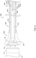
- FIG. 9 is a partial cross-section of a distal portion and proximal portion of another alternative delivery device 500.
- the delivery device 500 may be similar in form and function to the delivery device 100 described above. However, for clarity some portions of the delivery device 500 are not illustrated including, but not limited to the outer tubular member, the intermediate tubular member, the distal holding section, and the handle assembly. It should be understood that while not shown these components may be present in the delivery device 500 and substantially the same as those described with respect to FIGS. 4 and 5 .
- the delivery device 500 may include an inner tubular member 502 configured to be disposed within a lumen of an intermediate tubular member.
- the inner tubular member 502 may extend from a proximal end portion 503 disposed within a handle assembly to a distal end region 504.
- a flared distal portion or funnel 506 may be formed as a separate component and coupled to the distal end region 504 of the inner tubular member 502.
- the funnel 506 may be formed as an integral structure with the inner tubular member 502. While not explicitly shown, the distal end region 504 and the funnel 506 may extend into distal holding section.
- the funnel 506 may be capable of engaging the device 10, and the inner tubular member 502 may be used to "push" the device 10 out from distal holding section so as to deploy and anchor device 10 within a target region (e.g., a region of the heart such as die right ventricle).
- a target region e.g., a region of the heart such as die right ventricle.
- the inner tubular member 502 may have a lumen 508 extending from the proximal end portion 503 to the distal end region 504 and through the funnel 506.
- the inner tubular member 502 may include a wall 512 configured to bifurcate the lumen 508 into a bilumen having a first lumen 510a and a second lumen 510b along a length adjacent the proximal portion 503 thereof.
- the wall 512 may extend across the width of lumen 508. It is contemplated that the wall 512 may extend along any length of the inner tubular member 502, desired.
- the wall 512 may extend from the proximal end, or adjacent to the proximal end of the inner tubular member 502 distally to any point along the length of the lumen 508 desired. It is further completed that the wall 512 may be positioned at a location intermediate to the proximal end portion 503 and the distal end portion 504 and extend for any length of the lumen 508, as desired. As shown in FIG. 9 , the wall 512, providing the bilumens 510a, 510b, may only extend within a proximal end region of the inner tubular member 502, such that a distal portion of the inner tubular member 502 extending distally therefrom may have a single lumen 508.
- the lumen 508 through the distal portion of the inner tubular member 502 may be in fluid communication with both of the lumens 510a, 510b of the proximal end region.
- the inner tubular member 502, the wall 512, and/or the funnel 506 may be formed using any number of techniques, including, but not limited to molding or extrusion. While the lumen 508 is described as being bifurcated into a bilumen, it is contemplated that the lumen 508 may be divided with any number of walls in a number of different configurations to divide the lumen 508 into as many lumens as desired, including, but not limited to three, four, five, or more.
- a tether 514 or other retaining feature may be used to releasably secure the device 10 to the delivery device 500.
- the tether 514 may be a single or unitary length of material that may extend from a proximal end of the lumen 508, through the funnel 506, through the opening 38 of the device 10 and return to the proximal end of the inner tubular member 502 through the lumen 508 such that both ends of the tether 514 are positioned adjacent to the third hub portion of the handle assembly.
- the ends of the tether 514 may be secured within a locking feature in the third hub portion.
- the tether 514 may be assembled with the implantable device 10 and the delivery device 500 such that a portion of the tether 514a passes through the first lumen 510a of the bifurcated portion of the lumen 508 and a second portion of the tether 514b passes through the second lumen 510b of the bifurcated portion of the lumen 508.
- the wall 512 may extend across the width of the lumen 508 such that the first and second lumens 510a, 510b are isolated from one another along a length of the wall 512.
- the wall 512 (and the first and second lumens 510a, 510b) may hold the tether 514 in a spaced relationship along a length of the wall 512 which may reduce and/or minimize twisting and/or tangling of the tether 514.
- the tether 514 may be assembled with the implantable device 10 and the delivery device 500 using a number of different techniques.
- a free end of the tether 514 may be passed through the opening 38 of the device 10.
- a vacuum may then be used to pull both free ends of the tether 514 through the lumen 508 of the inner tubular member 502 to the proximal end of the inner tubular member 502 where the free ends of the tether 514 can be secured within the handle assembly.
- a free end may be positioned in each of the lumens 510a, 510b of the bifurcated portion of the lumen 508 such a portion of the tether 514 is disposed within each lumen 510a, 510b after assembly.
- a stylet or a pull wire may be used to assemble the tether with die implantable device 10 and the delivery device 500.
- a stylet or pull wire may be used to guide a free end of the tether 514 through a first lumen 510a of the bifurcated portion of the lumen 508, then through the opening 38 in the device 10, and then back through the second lumen 510b of the bifurcated portion of the lumen 508.
- the free end may then be pulled proximally through the lumen 508 to the handle assembly. It is contemplated that the second free end (e.g., the end not being advanced through the distal portion of the delivery device 500) may remain near the proximal end of the delivery device 500.
- both free ends can be secured within the handle assembly.
- the tether 514 may be assembled with the implantable device 10 and the delivery device 500 in any manner desired.
- the device 10 may still be affixed to the delivery device 100, 200, 300, 400, 500 through the tether 112, 212, 312, 412, 512.
- the fixation of the device 10 and/or the electrical performance of the device 10 may be removed. It is contemplated that the fixation of the device 10 (e.g., how well the hooks 26 are secured to the heart tissue) may be tested by gently tugging on the ends of the tether 112, 212, 312, 412, 512.
- the tether 112, 212, 312, 412, 512 may be removed by unlocking the tether lock 164 (see, for example, FIG. 4 ), removing the tether cap 166 (see, for example, FIG. 4 ), cutting the tether 112, 212, 312, 412, 512 at some location along its length, and pulling on one of the ends until the opposite end has passed through the opening 38 of the device 10 such that the device 10 is free from the tether 112, 212, 312, 412, 512.
- the tether cap 166 may include a means to separate the tether strands, including but not limited to, bifurcated lumens, clamping mechanisms, etc.
- the bifurcation of the lumen 208, 308, 408, 508 of the inner tubular member 208, 308, 408, 508 may facilitate removal of the tether 212, 312, 412, 512 by reducing or minimizing twisting or tangling of the tether 212, 312, 412, 512.
- reducing the twisting or tangling of the tether 212, 312, 412, 512 may reduce the force required to disengage the tether 212, 312, 412, 512 from the implantable device 10.
- the tether 112 may be affixed to a portion of the tether cap 166 (e.g., creating a loop) such that the tether 112 must be cut to allow the device 10 to be freed from the tether 112.
- the materials that can be used for the various components of the delivery devices such as delivery device 100, 200, 300, 400, 500 (and/or other delivery structures disclosed herein) and the various members disclosed herein may include those commonly associated with medical devices.
- delivery device 100, 200, 300, 400, 500 and components of thereof are commonly associated with medical devices.
- this is not intended to limit the devices and methods described herein, as the discussion may be applied to other similar delivery systems and/or components of delivery systems or devices disclosed herein.
- the delivery device 100, 200, 300, 400, 500 and/or other components of delivery system may be made from a metal, metal alloy, polymer (some examples of which are disclosed below), a metal-polymer composite, ceramics, combinations thereof, and the like, or other suitable material.
- suitable polymers may include polytetrafluoroethylene (PTFE), ethylene tetrafluoroethylene (ETFE), fluorinated ethylene propylene (FEP), polyoxymethylene (POM, for example, DELRIN ® available from DuPont), polyether block ester, polyurethane (for example, Polyurethane 85A), polypropylene (PP), polyvinylchloride (PVC), polyether-ester (for example, ARNITEL ® available from DSM Engineering Plastics), ether or ester based copolymers (for example, butylene/poly(alkylene ether) phthalate and/or other polyester elastomers such as HYTREL ® available from DuPont), polyamide (for example, DURETHAN ® available from Bayer or CRISTAMID ® available from Elf Atochem), elastomeric polyamides, block polyamide/ethers, polyether block amide (PEBA, for example available under the trade name PEBAX ®
- suitable metals and metal alloys include stainless steel, such as 304V, 304L, and 316LV stainless steel; mild steel, nickel-titanium alloy such as linear-elastic and/or super-elastic nitinol; other nickel alloys such as nickel-chromium-molybdenum alloys (e.g., UNS: N06625 such as INCONEL ® 625, UNS: N06022 such as HASTELLOY ® C-22 ® , UNS: N10276 such as HASTELLOY ® C276 ® , other HASTELLOY ® alloys, and the like), nickel-copper alloys (e.g., UNS: N04400 such as MONEL ® 400, NICKELVAC ® 400, NICORROS ® 400, and the like), nickel-cobalt-chromium-molybdenum alloys (e.g., UNS: R30035 such as MP35-N ® and the like), nickel-co
- portions or all of the delivery device 100, 200, 300, 400, 500 and/or other components of delivery system may be doped with, made of, or otherwise include a radiopaque material.
- Radiopaque materials are understood to be materials capable of producing a relatively bright image on a fluoroscopy screen or another imaging technique during a medical procedure. This relatively bright image aids the user of the delivery device 100 in determining its location.
- Some examples of radiopaque materials can include, but are not limited to, gold, platinum, palladium, tantalum, tungsten alloy, polymer material loaded with a radiopaque filler, and the like. Additionally, other radiopaque marker bands and/or coils may also be incorporated into the design of the delivery device 100 to achieve the same result.
Landscapes
- Health & Medical Sciences (AREA)
- Animal Behavior & Ethology (AREA)
- Biomedical Technology (AREA)
- Nuclear Medicine, Radiotherapy & Molecular Imaging (AREA)
- Radiology & Medical Imaging (AREA)
- Life Sciences & Earth Sciences (AREA)
- Engineering & Computer Science (AREA)
- General Health & Medical Sciences (AREA)
- Public Health (AREA)
- Veterinary Medicine (AREA)
- Heart & Thoracic Surgery (AREA)
- Cardiology (AREA)
- Electrotherapy Devices (AREA)
Applications Claiming Priority (2)
| Application Number | Priority Date | Filing Date | Title |
|---|---|---|---|
| US201662439261P | 2016-12-27 | 2016-12-27 | |
| PCT/US2017/068157 WO2018136203A1 (en) | 2016-12-27 | 2017-12-22 | Delivery devices and methods for leadless cardiac devices |
Publications (2)
| Publication Number | Publication Date |
|---|---|
| EP3562545A1 EP3562545A1 (en) | 2019-11-06 |
| EP3562545B1 true EP3562545B1 (en) | 2023-11-08 |
Family
ID=62148447
Family Applications (1)
| Application Number | Title | Priority Date | Filing Date |
|---|---|---|---|
| EP17870643.8A Active EP3562545B1 (en) | 2016-12-27 | 2017-12-22 | Delivery devices and methods for leadless cardiac devices |
Country Status (4)
| Country | Link |
|---|---|
| US (1) | US10894162B2 (zh) |
| EP (1) | EP3562545B1 (zh) |
| CN (1) | CN110114114B (zh) |
| WO (1) | WO2018136203A1 (zh) |
Families Citing this family (5)
| Publication number | Priority date | Publication date | Assignee | Title |
|---|---|---|---|---|
| US10926093B2 (en) | 2016-05-05 | 2021-02-23 | Pacesetter, Inc. | System and method for loading a leadless pacemaker onto a catheter-based delivery system |
| US10398876B2 (en) | 2017-04-26 | 2019-09-03 | Pacesetter, Inc. | System and methods for leadless pacing using negative pressure |
| US11524139B2 (en) | 2019-07-15 | 2022-12-13 | Medtronic, Inc. | Catheter with active return curve |
| US11524143B2 (en) * | 2019-07-15 | 2022-12-13 | Medtronic, Inc. | Catheter with distal and proximal fixation members |
| US20240001112A1 (en) * | 2022-07-01 | 2024-01-04 | Pacesetter, Inc. | Biostimulator transport system having flexible tether |
Family Cites Families (164)
| Publication number | Priority date | Publication date | Assignee | Title |
|---|---|---|---|---|
| US4301815A (en) | 1980-01-23 | 1981-11-24 | Telectronics Pty. Limited | Trailing tine electrode lead |
| US5814029A (en) | 1994-11-03 | 1998-09-29 | Daig Corporation | Guiding introducer system for use in ablation and mapping procedures in the left ventricle |
| US5807399A (en) | 1996-10-23 | 1998-09-15 | Medtronic, Inc. | Method for removal of chronically implanted leads and leads optimized for use therewith |
| US6395017B1 (en) | 1996-11-15 | 2002-05-28 | C. R. Bard, Inc. | Endoprosthesis delivery catheter with sequential stage control |
| US5908381A (en) | 1997-04-30 | 1999-06-01 | C. R. Bard Inc. | Directional surgical device for use with endoscope, gastroscope, colonoscope or the like |
| US6409674B1 (en) | 1998-09-24 | 2002-06-25 | Data Sciences International, Inc. | Implantable sensor with wireless communication |
| US6224725B1 (en) | 1999-02-09 | 2001-05-01 | Isoflux, Inc. | Unbalanced magnetron sputtering with auxiliary cathode |
| ES2230826T3 (es) | 1999-04-02 | 2005-05-01 | Sorin Biomedica Crm S.R.L. | Estructura de anclaje para electrodos implantables. |
| US6582441B1 (en) | 2000-02-24 | 2003-06-24 | Advanced Bionics Corporation | Surgical insertion tool |
| US6638268B2 (en) | 2000-04-07 | 2003-10-28 | Imran K. Niazi | Catheter to cannulate the coronary sinus |
| US6497803B2 (en) | 2000-05-31 | 2002-12-24 | Isoflux, Inc. | Unbalanced plasma generating apparatus having cylindrical symmetry |
| US6551477B2 (en) | 2000-09-25 | 2003-04-22 | Isoflux, Inc. | Interlocking cylindrical magnetron cathodes and targets |
| US6786918B1 (en) | 2000-10-17 | 2004-09-07 | Medtronic Vascular, Inc. | Stent delivery system |
| US6866669B2 (en) | 2001-10-12 | 2005-03-15 | Cordis Corporation | Locking handle deployment mechanism for medical device and method |
| US20030078618A1 (en) | 2001-10-19 | 2003-04-24 | Fey Kate E. | System and method for removing implanted devices |
| US7993351B2 (en) | 2002-07-24 | 2011-08-09 | Pressure Products Medical Supplies, Inc. | Telescopic introducer with a compound curvature for inducing alignment and method of using the same |
| US8303511B2 (en) | 2002-09-26 | 2012-11-06 | Pacesetter, Inc. | Implantable pressure transducer system optimized for reduced thrombosis effect |
| US20040093056A1 (en) | 2002-10-26 | 2004-05-13 | Johnson Lianw M. | Medical appliance delivery apparatus and method of use |
| US7499758B2 (en) | 2003-04-11 | 2009-03-03 | Cardiac Pacemakers, Inc. | Helical fixation elements for subcutaneous electrodes |
| ATE364348T1 (de) | 2003-06-17 | 2007-07-15 | Raymond Moser | Implantierbare und wiederherausziehbare sensorvorrichtung |
| JP4496223B2 (ja) | 2003-11-06 | 2010-07-07 | エヌエムティー メディカル, インコーポレイティッド | 中隔貫通穿刺装置 |
| US8002822B2 (en) | 2004-01-22 | 2011-08-23 | Isoflux, Inc. | Radiopaque coating for biomedical devices |
| US20050165472A1 (en) | 2004-01-22 | 2005-07-28 | Glocker David A. | Radiopaque coating for biomedical devices |
| US20050209653A1 (en) | 2004-03-16 | 2005-09-22 | Medtronic, Inc. | Intra-luminal device for gastrointestinal electrical stimulation |
| US20050267555A1 (en) | 2004-05-28 | 2005-12-01 | Marnfeldt Goran N | Engagement tool for implantable medical devices |
| WO2006004645A2 (en) | 2004-06-28 | 2006-01-12 | Isoflux, Inc. | Porous coatings for biomedical implants |
| US7678081B2 (en) | 2004-07-12 | 2010-03-16 | Pacesetter, Inc. | Methods and devices for transseptal access |
| US7321798B2 (en) | 2005-03-31 | 2008-01-22 | Medtronic, Inc. | Trans-septal/trans-myocardial ventricular pacing lead |
| EP1981432B1 (en) | 2005-06-30 | 2012-10-03 | Abbott Laboratories | Delivery system for a medical device |
| EP2471452B1 (en) | 2005-10-14 | 2014-12-10 | Pacesetter, Inc. | Cardiac pacing system and method of conveying information therein |
| WO2007068284A1 (en) | 2005-12-12 | 2007-06-21 | Synergio Ag | Intra cardiac device, system and methods |
| DE102006014698A1 (de) | 2006-03-30 | 2007-10-04 | Biotronik Crm Patent Ag | Medizinische, implantierbare Elektrodenvorrichtung |
| US7937161B2 (en) | 2006-03-31 | 2011-05-03 | Boston Scientific Scimed, Inc. | Cardiac stimulation electrodes, delivery devices, and implantation configurations |
| US7840281B2 (en) | 2006-07-21 | 2010-11-23 | Boston Scientific Scimed, Inc. | Delivery of cardiac stimulation devices |
| US20090082828A1 (en) | 2007-09-20 | 2009-03-26 | Alan Ostroff | Leadless Cardiac Pacemaker with Secondary Fixation Capability |
| WO2009120636A1 (en) | 2008-03-25 | 2009-10-01 | Ebr Systems, Inc. | Temporary electrode connection for wireless pacing systems |
| US8527068B2 (en) | 2009-02-02 | 2013-09-03 | Nanostim, Inc. | Leadless cardiac pacemaker with secondary fixation capability |
| US20100274227A1 (en) | 2009-02-13 | 2010-10-28 | Alexander Khairkhahan | Delivery catheter handle cover |
| US20110112548A1 (en) | 2009-11-06 | 2011-05-12 | Daniel Fifer | Methods and systems for removal of implantable intravascular devices |
| US8352028B2 (en) | 2010-03-26 | 2013-01-08 | Medtronic, Inc. | Intravascular medical device |
| US8532790B2 (en) | 2010-04-13 | 2013-09-10 | Medtronic, Inc. | Slidable fixation device for securing a medical implant |
| US8478431B2 (en) | 2010-04-13 | 2013-07-02 | Medtronic, Inc. | Slidable fixation device for securing a medical implant |
| US20110270340A1 (en) | 2010-04-30 | 2011-11-03 | Medtronic Vascular,Inc. | Two-Stage Delivery Systems and Methods for Fixing a Leadless Implant to Tissue |
| US20110270339A1 (en) | 2010-04-30 | 2011-11-03 | Medtronic Vascular, Inc. | Two-Stage Delivery Systems and Methods for Fixing a Leadless Implant to Tissue |
| EP2394695B1 (fr) | 2010-06-14 | 2012-09-26 | Sorin CRM SAS | Capsule intracardiaque autonome et son accessoire d'implantation |
| US20120095539A1 (en) | 2010-10-13 | 2012-04-19 | Alexander Khairkhahan | Delivery Catheter Systems and Methods |
| US9020611B2 (en) | 2010-10-13 | 2015-04-28 | Pacesetter, Inc. | Leadless cardiac pacemaker with anti-unscrewing feature |
| US9504820B2 (en) | 2010-10-29 | 2016-11-29 | Medtronic, Inc. | System and method for implantation of an implantable medical device |
| US9204842B2 (en) | 2010-10-29 | 2015-12-08 | Medtronic, Inc. | Medical device fixation attachment mechanism |
| US9072872B2 (en) | 2010-10-29 | 2015-07-07 | Medtronic, Inc. | Telescoping catheter delivery system for left heart endocardial device placement |
| US20120109148A1 (en) | 2010-10-29 | 2012-05-03 | Medtronic, Inc. | System and method for retrieval of an implantable medical device |
| US9126032B2 (en) | 2010-12-13 | 2015-09-08 | Pacesetter, Inc. | Pacemaker retrieval systems and methods |
| WO2012082735A1 (en) | 2010-12-13 | 2012-06-21 | Nanostim, Inc. | Delivery catheter systems and methods |
| EP2654889B1 (en) | 2010-12-20 | 2017-03-01 | Pacesetter, Inc. | Leadless pacemaker with radial fixation mechanism |
| US20160228715A9 (en) | 2010-12-29 | 2016-08-11 | Medtronic, Inc. | Implantable medical device fixation |
| US10112045B2 (en) * | 2010-12-29 | 2018-10-30 | Medtronic, Inc. | Implantable medical device fixation |
| US9775982B2 (en) | 2010-12-29 | 2017-10-03 | Medtronic, Inc. | Implantable medical device fixation |
| US20120172891A1 (en) | 2010-12-29 | 2012-07-05 | Medtronic, Inc. | Implantable medical device fixation testing |
| US8727996B2 (en) | 2011-04-20 | 2014-05-20 | Medtronic Vascular, Inc. | Delivery system for implantable medical device |
| US8926588B2 (en) | 2011-07-05 | 2015-01-06 | Medtronic Vascular, Inc. | Steerable delivery catheter |
| US8758365B2 (en) | 2011-08-03 | 2014-06-24 | Medtronic, Inc. | Implant system including guiding accessory and methods of use |
| US20130035636A1 (en) | 2011-08-03 | 2013-02-07 | Medtronic Vascular, Inc. | Delivery and Deployment Catheter for an Implantable Medical Device |
| US8504156B2 (en) | 2011-08-26 | 2013-08-06 | Medtronic, Inc. | Holding members for implantable cardiac stimulation devices |
| US8945145B2 (en) | 2011-09-22 | 2015-02-03 | Medtronic, Inc. | Delivery system assemblies for implantable medical devices |
| US9101281B2 (en) | 2011-09-27 | 2015-08-11 | Medtronic, Inc. | IMD stability monitor |
| US8945146B2 (en) | 2011-10-24 | 2015-02-03 | Medtronic, Inc. | Delivery system assemblies and associated methods for implantable medical devices |
| US8634912B2 (en) | 2011-11-04 | 2014-01-21 | Pacesetter, Inc. | Dual-chamber leadless intra-cardiac medical device with intra-cardiac extension |
| US8781605B2 (en) | 2011-10-31 | 2014-07-15 | Pacesetter, Inc. | Unitary dual-chamber leadless intra-cardiac medical device and method of implanting same |
| WO2013067496A2 (en) | 2011-11-04 | 2013-05-10 | Nanostim, Inc. | Leadless cardiac pacemaker with integral battery and redundant welds |
| US8721587B2 (en) | 2011-11-17 | 2014-05-13 | Medtronic, Inc. | Delivery system assemblies and associated methods for implantable medical devices |
| US9216293B2 (en) | 2011-11-17 | 2015-12-22 | Medtronic, Inc. | Delivery system assemblies for implantable medical devices |
| US10485435B2 (en) | 2012-03-26 | 2019-11-26 | Medtronic, Inc. | Pass-through implantable medical device delivery catheter with removeable distal tip |
| US9220906B2 (en) | 2012-03-26 | 2015-12-29 | Medtronic, Inc. | Tethered implantable medical device deployment |
| US9339197B2 (en) | 2012-03-26 | 2016-05-17 | Medtronic, Inc. | Intravascular implantable medical device introduction |
| US9833625B2 (en) | 2012-03-26 | 2017-12-05 | Medtronic, Inc. | Implantable medical device delivery with inner and outer sheaths |
| US20130253342A1 (en) | 2012-03-26 | 2013-09-26 | Medtronic, Inc. | Pass-through implantable medical device delivery catheter |
| US9717421B2 (en) | 2012-03-26 | 2017-08-01 | Medtronic, Inc. | Implantable medical device delivery catheter with tether |
| US20140018818A1 (en) | 2012-07-12 | 2014-01-16 | Pacesetter, Inc. | System and method of implanting a medical device |
| US9808617B2 (en) | 2012-08-21 | 2017-11-07 | Pacesetter, Inc. | X-ray identification for active implantable medical device |
| US9351648B2 (en) | 2012-08-24 | 2016-05-31 | Medtronic, Inc. | Implantable medical device electrode assembly |
| US9308365B2 (en) | 2012-11-27 | 2016-04-12 | Biotronik Se & Co. Kg | Detachable electrode and anchor |
| US9238145B2 (en) | 2012-11-27 | 2016-01-19 | Biotronik Se & Co. Kg | Leadless implantable device delivery apparatus |
| US9168372B2 (en) | 2013-03-07 | 2015-10-27 | Pacesetter, Inc. | Temporary leadless implantable medical device with indwelling retrieval mechanism |
| US9358387B2 (en) | 2013-04-09 | 2016-06-07 | Biotronik Se & Co Kg | Leadless pacemaker |
| US9421384B2 (en) | 2013-04-18 | 2016-08-23 | Biotronik Se & Co. Kg | Implantable medical device |
| US8948883B2 (en) | 2013-04-24 | 2015-02-03 | Medtronic, Inc. | Electrode assemblies and associated fixation members for implantable medical devices |
| EP2818201B1 (fr) | 2013-06-24 | 2016-07-20 | Sorin CRM SAS | Capsule intracardiaque et accessoire d'implantation in situ par voie fémorale |
| US9155882B2 (en) | 2013-07-31 | 2015-10-13 | Medtronic, Inc. | Implantable medical devices including tine fixation component having hook segment |
| US9119959B2 (en) | 2013-07-31 | 2015-09-01 | Medtronic, Inc. | Tine fixation components for implantable medical devices |
| US10071243B2 (en) | 2013-07-31 | 2018-09-11 | Medtronic, Inc. | Fixation for implantable medical devices |
| US10722723B2 (en) | 2013-08-16 | 2020-07-28 | Cardiac Pacemakers, Inc. | Delivery devices and methods for leadless cardiac devices |
| US9393427B2 (en) | 2013-08-16 | 2016-07-19 | Cardiac Pacemakers, Inc. | Leadless cardiac pacemaker with delivery and/or retrieval features |
| ES2666373T3 (es) | 2013-08-16 | 2018-05-04 | Cardiac Pacemakers, Inc. | Dispositivos de administración para dispositivos cardiacos sin cables |
| US10842993B2 (en) | 2013-08-16 | 2020-11-24 | Cardiac Pacemakers, Inc. | Leadless cardiac pacing devices |
| JP6182675B2 (ja) | 2013-08-16 | 2017-08-16 | カーディアック ペースメイカーズ, インコーポレイテッド | リードレス心臓ペースメーカおよび回収デバイス |
| US9480850B2 (en) | 2013-08-16 | 2016-11-01 | Cardiac Pacemakers, Inc. | Leadless cardiac pacemaker and retrieval device |
| EP3033141B1 (en) | 2013-08-16 | 2017-10-11 | Cardiac Pacemakers, Inc. | Leadless cardiac pacing devices |
| US9492674B2 (en) | 2013-08-16 | 2016-11-15 | Cardiac Pacemakers, Inc. | Leadless cardiac pacemaker with delivery and/or retrieval features |
| US10300286B2 (en) * | 2013-09-27 | 2019-05-28 | Medtronic, Inc. | Tools and assemblies thereof for implantable medical devices |
| US9526522B2 (en) | 2013-09-27 | 2016-12-27 | Medtronic, Inc. | Interventional medical systems, tools, and assemblies |
| EP2881141B1 (fr) | 2013-12-04 | 2016-06-01 | Sorin CRM SAS | Capsule intracardiaque implantable sur une paroi mince, notamment la paroi septale |
| US9764139B2 (en) | 2014-01-24 | 2017-09-19 | Medtronic, Inc. | Pre-implant detection |
| US9283382B2 (en) * | 2014-04-01 | 2016-03-15 | Medtronic, Inc. | Interventional medical systems, tools, and associated methods |
| US9861815B2 (en) * | 2014-04-01 | 2018-01-09 | Medtronic, Inc. | Interventional medical systems, tools, and subassemblies |
| EP2929910B1 (fr) | 2014-04-08 | 2016-11-16 | Sorin CRM SAS | Capsule intracardiaque et son accessoire d'explantation |
| WO2015168155A1 (en) | 2014-04-29 | 2015-11-05 | Cardiac Pacemakers, Inc. | Leadless cardiac pacemaker with retrieval features |
| US10080887B2 (en) | 2014-04-29 | 2018-09-25 | Cardiac Pacemakers, Inc. | Leadless cardiac pacing devices including tissue engagement verification |
| EP2954930B1 (en) | 2014-06-10 | 2019-04-10 | BIOTRONIK SE & Co. KG | Delivery system for an implantable medical device |
| EP2959936B1 (fr) | 2014-06-25 | 2021-03-31 | Sorin CRM SAS | Capsule inplantable à fixation par vissage, notamment capsule autonome de stimulation cardiaque |
| FR3022790A1 (fr) | 2014-06-25 | 2016-01-01 | Sorin Crm Sas | Capsule implantable a fixation par vissage, notamment capsule autonome de stimulation cardiaque |
| US9539423B2 (en) | 2014-07-17 | 2017-01-10 | Medtronic, Inc. | Interventional medical systems, tools, and methods of use |
| US10390720B2 (en) | 2014-07-17 | 2019-08-27 | Medtronic, Inc. | Leadless pacing system including sensing extension |
| US9446248B2 (en) | 2014-07-17 | 2016-09-20 | Medtronic, Inc. | Interventional medical systems, tools, and methods of use |
| US10478620B2 (en) | 2014-08-26 | 2019-11-19 | Medtronic, Inc. | Interventional medical systems, devices, and methods of use |
| US9675798B2 (en) | 2014-08-26 | 2017-06-13 | Medtronic, Inc. | Interventional medical systems, devices, and components thereof |
| US10441777B2 (en) | 2014-09-09 | 2019-10-15 | Pacesetter, Inc. | Implantable medical device having restrained tether device |
| US10716931B2 (en) | 2014-09-09 | 2020-07-21 | Pacesetter, Inc. | Systems and methods for implanting a medical device |
| US10653859B2 (en) | 2014-10-07 | 2020-05-19 | Pacesetter, Inc. | Delivery catheter systems and methods |
| EP3485939B1 (en) | 2014-10-22 | 2020-07-15 | Cardiac Pacemakers, Inc. | Delivery devices for leadless cardiac devices |
| US9623234B2 (en) | 2014-11-11 | 2017-04-18 | Medtronic, Inc. | Leadless pacing device implantation |
| US9414857B2 (en) | 2014-11-20 | 2016-08-16 | Medtronic, Inc. | Delivery system assemblies for implantable medical devices |
| US20160206872A1 (en) | 2015-01-16 | 2016-07-21 | Medtronic, Inc. | Interventional medical tools and assemblies |
| EP3056157B1 (en) | 2015-01-23 | 2018-03-14 | BIOTRONIK SE & Co. KG | A medical implant with a proximal rigid fastener for interaction with a coupling element of a catheter |
| US11207530B2 (en) * | 2015-02-03 | 2021-12-28 | Medtronic, Inc. | Relatively compact implantable medical devices and associated methods for loading the devices into a delivery catheter |
| US9750931B2 (en) | 2015-02-12 | 2017-09-05 | Medtronic, Inc. | Interventional medical systems, assemblies and methods |
| US10052127B2 (en) | 2015-02-25 | 2018-08-21 | Medtronic, Inc. | Catheters for deploying implantable medical devices, and associated tethering assemblies and methods |
| US9533163B2 (en) | 2015-02-27 | 2017-01-03 | Pacesetter, Inc. | Systems and methods for implantable medical device communication |
| US9724507B2 (en) | 2015-03-13 | 2017-08-08 | Medtronic, Inc. | Interventional medical systems and associated tethering assemblies and methods |
| EP3069754B1 (fr) | 2015-03-16 | 2017-10-25 | Sorin CRM SAS | Accessoire d'implantation in situ pour capsule intracardiaque autonome |
| US9993648B2 (en) | 2015-03-27 | 2018-06-12 | Medtronic, Inc. | Medical device delivery system |
| US9610454B2 (en) | 2015-04-13 | 2017-04-04 | Pacesetter, Inc. | Over torque limiter for leadless implantable medical devices |
| US9867964B2 (en) | 2015-04-23 | 2018-01-16 | Medtronic, Inc. | Interventional medical systems, assemblies, and construction methods |
| US10449354B2 (en) | 2015-04-23 | 2019-10-22 | Medtronics, Inc. | Intracardiac medical device |
| US10130821B2 (en) | 2015-04-24 | 2018-11-20 | Medtronic, Inc. | Interventional medical systems and associated tethering assemblies and methods |
| US9526891B2 (en) | 2015-04-24 | 2016-12-27 | Medtronic, Inc. | Intracardiac medical device |
| US9468773B1 (en) | 2015-05-07 | 2016-10-18 | Medtronic, Inc. | Interventional medical systems and implantable medical devices including tethering features, and associated methods |
| US10143838B2 (en) | 2015-05-13 | 2018-12-04 | Medtronic, Inc. | Securing an implantable medical device in position while reducing perforations |
| US10350416B2 (en) | 2015-07-28 | 2019-07-16 | Medtronic, Inc. | Intracardiac pacemaker with sensing extension in pulmonary artery |
| US10525256B2 (en) | 2015-07-29 | 2020-01-07 | Medtronic, Inc. | Interventional medical systems, catheters, and methods |
| US20170043158A1 (en) | 2015-08-12 | 2017-02-16 | Medtronic, Inc. | Interventional medical systems and catheters |
| US10292621B2 (en) | 2015-09-08 | 2019-05-21 | Pacesetter, Inc. | Systems and methods for retrieving an implantable device |
| US10391306B2 (en) | 2015-09-11 | 2019-08-27 | Pacesetter, Inc. | Tube-cut helical fixation anchor for electrotherapy device |
| US10758729B2 (en) | 2015-10-01 | 2020-09-01 | Medtronic, Inc. | Interventional medical systems, catheters, and methods |
| US9844664B2 (en) | 2015-10-12 | 2017-12-19 | Medtronic, Inc. | Interventional medical systems, catheters, and subassemblies |
| US9907953B2 (en) | 2015-10-15 | 2018-03-06 | Pacesetter, Inc. | Fixation sleeve equipped leadless pulse generator |
| US10434283B2 (en) | 2015-10-29 | 2019-10-08 | Medtronic, Inc. | Interventional medical systems, associated assemblies and methods |
| US10080888B2 (en) | 2015-11-16 | 2018-09-25 | Medtronic, Inc. | Interventional medical systems and associated methods |
| WO2017087661A1 (en) | 2015-11-20 | 2017-05-26 | Cardiac Pacemakers, Inc. | Delivery devices and methods for leadless cardiac devices |
| EP3377174B1 (en) | 2015-11-20 | 2019-08-28 | Cardiac Pacemakers, Inc. | Delivery systems for leadless cardiac devices |
| EP3173126B1 (fr) | 2015-11-27 | 2020-03-25 | Sorin CRM SAS | Capsule implantable, notamment capsule autonome de stimulation cardiaque, et son procede d'assemblage |
| US10099050B2 (en) | 2016-01-21 | 2018-10-16 | Medtronic, Inc. | Interventional medical devices, device systems, and fixation components thereof |
| US10463853B2 (en) | 2016-01-21 | 2019-11-05 | Medtronic, Inc. | Interventional medical systems |
| EP3884994B1 (en) | 2016-01-26 | 2024-02-28 | Medtronic, Inc. | Delivery device |
| WO2017136548A1 (en) | 2016-02-04 | 2017-08-10 | Cardiac Pacemakers, Inc. | Delivery system with force sensor for leadless cardiac device |
| US10780280B2 (en) | 2016-04-26 | 2020-09-22 | Mayo Foundation For Medical Education And Research | Devices and methods for cardiac pacing and resynchronization |
| US10350408B2 (en) | 2016-04-28 | 2019-07-16 | Medtronic, Inc. | Interventional medical systems, associated assemblies and methods |
| US10143823B2 (en) | 2016-04-29 | 2018-12-04 | Medtronic, Inc. | Interventional medical systems and improved assemblies thereof and associated methods of use |
| US10926093B2 (en) | 2016-05-05 | 2021-02-23 | Pacesetter, Inc. | System and method for loading a leadless pacemaker onto a catheter-based delivery system |
| US20170326369A1 (en) | 2016-05-10 | 2017-11-16 | Cardiac Pacemakers, Inc. | Trans septal implantable medical device |
| US10328272B2 (en) | 2016-05-10 | 2019-06-25 | Cardiac Pacemakers, Inc. | Retrievability for implantable medical devices |
| US10668294B2 (en) | 2016-05-10 | 2020-06-02 | Cardiac Pacemakers, Inc. | Leadless cardiac pacemaker configured for over the wire delivery |
| US10881868B2 (en) | 2016-05-24 | 2021-01-05 | Sorin Crm Sas | Torque limiting mechanism between a medical device and its implantation accessory |
| US10542964B2 (en) | 2016-05-25 | 2020-01-28 | Medtronic, Inc. | Interventional medical device retrieval |
| US10300287B2 (en) | 2016-06-27 | 2019-05-28 | Medtronic, Inc. | Delivery systems for implantable medical devices, and associated tethering assemblies and methods |
-
2017
- 2017-12-22 CN CN201780080994.4A patent/CN110114114B/zh active Active
- 2017-12-22 US US15/852,384 patent/US10894162B2/en active Active
- 2017-12-22 WO PCT/US2017/068157 patent/WO2018136203A1/en unknown
- 2017-12-22 EP EP17870643.8A patent/EP3562545B1/en active Active
Also Published As
| Publication number | Publication date |
|---|---|
| CN110114114A (zh) | 2019-08-09 |
| US20180178006A1 (en) | 2018-06-28 |
| CN110114114B (zh) | 2023-05-02 |
| WO2018136203A1 (en) | 2018-07-26 |
| US10894162B2 (en) | 2021-01-19 |
| EP3562545A1 (en) | 2019-11-06 |
Similar Documents
| Publication | Publication Date | Title |
|---|---|---|
| US10981008B2 (en) | Delivery devices and methods for leadless cardiac devices | |
| US10258802B2 (en) | Delivery devices and methods for leadless cardiac devices | |
| US11389649B2 (en) | Delivery devices and methods for leadless cardiac devices | |
| US10737092B2 (en) | Delivery devices and methods for leadless cardiac devices | |
| US11577085B2 (en) | Delivery devices and methods for leadless cardiac devices | |
| US20180178007A1 (en) | Delivery devices and methods for leadless cardiac devices | |
| US20220176110A1 (en) | Delivery devices and methods for leadless cardiac devices | |
| EP3562545B1 (en) | Delivery devices and methods for leadless cardiac devices | |
| US20220054847A1 (en) | Catheter and leadless cardiac devices including electrical pathway barrier | |
| US11541245B2 (en) | Delivery devices and methods for leadless cardiac devices | |
| EP3562547B1 (en) | Leadless delivery catheter with conductive pathway |
Legal Events
| Date | Code | Title | Description |
|---|---|---|---|
| STAA | Information on the status of an ep patent application or granted ep patent |
Free format text: STATUS: UNKNOWN |
|
| STAA | Information on the status of an ep patent application or granted ep patent |
Free format text: STATUS: THE INTERNATIONAL PUBLICATION HAS BEEN MADE |
|
| PUAI | Public reference made under article 153(3) epc to a published international application that has entered the european phase |
Free format text: ORIGINAL CODE: 0009012 |
|
| STAA | Information on the status of an ep patent application or granted ep patent |
Free format text: STATUS: REQUEST FOR EXAMINATION WAS MADE |
|
| 17P | Request for examination filed |
Effective date: 20190722 |
|
| AK | Designated contracting states |
Kind code of ref document: A1 Designated state(s): AL AT BE BG CH CY CZ DE DK EE ES FI FR GB GR HR HU IE IS IT LI LT LU LV MC MK MT NL NO PL PT RO RS SE SI SK SM TR |
|
| AX | Request for extension of the european patent |
Extension state: BA ME |
|
| DAV | Request for validation of the european patent (deleted) | ||
| DAX | Request for extension of the european patent (deleted) | ||
| STAA | Information on the status of an ep patent application or granted ep patent |
Free format text: STATUS: EXAMINATION IS IN PROGRESS |
|
| 17Q | First examination report despatched |
Effective date: 20220829 |
|
| GRAP | Despatch of communication of intention to grant a patent |
Free format text: ORIGINAL CODE: EPIDOSNIGR1 |
|
| STAA | Information on the status of an ep patent application or granted ep patent |
Free format text: STATUS: GRANT OF PATENT IS INTENDED |
|
| RIC1 | Information provided on ipc code assigned before grant |
Ipc: A61N 1/375 20060101ALI20230502BHEP Ipc: A61N 1/372 20060101AFI20230502BHEP |
|
| INTG | Intention to grant announced |
Effective date: 20230522 |
|
| GRAS | Grant fee paid |
Free format text: ORIGINAL CODE: EPIDOSNIGR3 |
|
| GRAA | (expected) grant |
Free format text: ORIGINAL CODE: 0009210 |
|
| STAA | Information on the status of an ep patent application or granted ep patent |
Free format text: STATUS: THE PATENT HAS BEEN GRANTED |
|
| AK | Designated contracting states |
Kind code of ref document: B1 Designated state(s): AL AT BE BG CH CY CZ DE DK EE ES FI FR GB GR HR HU IE IS IT LI LT LU LV MC MK MT NL NO PL PT RO RS SE SI SK SM TR |
|
| REG | Reference to a national code |
Ref country code: GB Ref legal event code: FG4D |
|
| REG | Reference to a national code |
Ref country code: CH Ref legal event code: EP |
|
| REG | Reference to a national code |
Ref country code: DE Ref legal event code: R096 Ref document number: 602017076400 Country of ref document: DE |
|
| REG | Reference to a national code |
Ref country code: IE Ref legal event code: FG4D |
|
| PGFP | Annual fee paid to national office [announced via postgrant information from national office to epo] |
Ref country code: GB Payment date: 20231219 Year of fee payment: 7 |
|
| PGFP | Annual fee paid to national office [announced via postgrant information from national office to epo] |
Ref country code: FR Payment date: 20231219 Year of fee payment: 7 Ref country code: DE Payment date: 20231219 Year of fee payment: 7 |
|
| REG | Reference to a national code |
Ref country code: LT Ref legal event code: MG9D |
|
| REG | Reference to a national code |
Ref country code: NL Ref legal event code: MP Effective date: 20231108 |
|
| PG25 | Lapsed in a contracting state [announced via postgrant information from national office to epo] |
Ref country code: GR Free format text: LAPSE BECAUSE OF FAILURE TO SUBMIT A TRANSLATION OF THE DESCRIPTION OR TO PAY THE FEE WITHIN THE PRESCRIBED TIME-LIMIT Effective date: 20240209 |
|
| PG25 | Lapsed in a contracting state [announced via postgrant information from national office to epo] |
Ref country code: IS Free format text: LAPSE BECAUSE OF FAILURE TO SUBMIT A TRANSLATION OF THE DESCRIPTION OR TO PAY THE FEE WITHIN THE PRESCRIBED TIME-LIMIT Effective date: 20240308 |
|
| PG25 | Lapsed in a contracting state [announced via postgrant information from national office to epo] |
Ref country code: LT Free format text: LAPSE BECAUSE OF FAILURE TO SUBMIT A TRANSLATION OF THE DESCRIPTION OR TO PAY THE FEE WITHIN THE PRESCRIBED TIME-LIMIT Effective date: 20231108 |
|
| REG | Reference to a national code |
Ref country code: AT Ref legal event code: MK05 Ref document number: 1629090 Country of ref document: AT Kind code of ref document: T Effective date: 20231108 |
|
| PG25 | Lapsed in a contracting state [announced via postgrant information from national office to epo] |
Ref country code: NL Free format text: LAPSE BECAUSE OF FAILURE TO SUBMIT A TRANSLATION OF THE DESCRIPTION OR TO PAY THE FEE WITHIN THE PRESCRIBED TIME-LIMIT Effective date: 20231108 |
|
| PG25 | Lapsed in a contracting state [announced via postgrant information from national office to epo] |
Ref country code: AT Free format text: LAPSE BECAUSE OF FAILURE TO SUBMIT A TRANSLATION OF THE DESCRIPTION OR TO PAY THE FEE WITHIN THE PRESCRIBED TIME-LIMIT Effective date: 20231108 |
|
| PG25 | Lapsed in a contracting state [announced via postgrant information from national office to epo] |
Ref country code: ES Free format text: LAPSE BECAUSE OF FAILURE TO SUBMIT A TRANSLATION OF THE DESCRIPTION OR TO PAY THE FEE WITHIN THE PRESCRIBED TIME-LIMIT Effective date: 20231108 |
|
| PG25 | Lapsed in a contracting state [announced via postgrant information from national office to epo] |
Ref country code: NL Free format text: LAPSE BECAUSE OF FAILURE TO SUBMIT A TRANSLATION OF THE DESCRIPTION OR TO PAY THE FEE WITHIN THE PRESCRIBED TIME-LIMIT Effective date: 20231108 Ref country code: LT Free format text: LAPSE BECAUSE OF FAILURE TO SUBMIT A TRANSLATION OF THE DESCRIPTION OR TO PAY THE FEE WITHIN THE PRESCRIBED TIME-LIMIT Effective date: 20231108 Ref country code: IS Free format text: LAPSE BECAUSE OF FAILURE TO SUBMIT A TRANSLATION OF THE DESCRIPTION OR TO PAY THE FEE WITHIN THE PRESCRIBED TIME-LIMIT Effective date: 20240308 Ref country code: GR Free format text: LAPSE BECAUSE OF FAILURE TO SUBMIT A TRANSLATION OF THE DESCRIPTION OR TO PAY THE FEE WITHIN THE PRESCRIBED TIME-LIMIT Effective date: 20240209 Ref country code: ES Free format text: LAPSE BECAUSE OF FAILURE TO SUBMIT A TRANSLATION OF THE DESCRIPTION OR TO PAY THE FEE WITHIN THE PRESCRIBED TIME-LIMIT Effective date: 20231108 Ref country code: BG Free format text: LAPSE BECAUSE OF FAILURE TO SUBMIT A TRANSLATION OF THE DESCRIPTION OR TO PAY THE FEE WITHIN THE PRESCRIBED TIME-LIMIT Effective date: 20240208 Ref country code: AT Free format text: LAPSE BECAUSE OF FAILURE TO SUBMIT A TRANSLATION OF THE DESCRIPTION OR TO PAY THE FEE WITHIN THE PRESCRIBED TIME-LIMIT Effective date: 20231108 Ref country code: PT Free format text: LAPSE BECAUSE OF FAILURE TO SUBMIT A TRANSLATION OF THE DESCRIPTION OR TO PAY THE FEE WITHIN THE PRESCRIBED TIME-LIMIT Effective date: 20240308 |