EP3562287B1 - Vorspanneinheit für einen t-bolzen - Google Patents
Vorspanneinheit für einen t-bolzen Download PDFInfo
- Publication number
- EP3562287B1 EP3562287B1 EP18169635.2A EP18169635A EP3562287B1 EP 3562287 B1 EP3562287 B1 EP 3562287B1 EP 18169635 A EP18169635 A EP 18169635A EP 3562287 B1 EP3562287 B1 EP 3562287B1
- Authority
- EP
- European Patent Office
- Prior art keywords
- bolt
- rack
- frame
- slider
- main frame
- Prior art date
- Legal status (The legal status is an assumption and is not a legal conclusion. Google has not performed a legal analysis and makes no representation as to the accuracy of the status listed.)
- Active
Links
Images



Classifications
-
- H—ELECTRICITY
- H05—ELECTRIC TECHNIQUES NOT OTHERWISE PROVIDED FOR
- H05K—PRINTED CIRCUITS; CASINGS OR CONSTRUCTIONAL DETAILS OF ELECTRIC APPARATUS; MANUFACTURE OF ASSEMBLAGES OF ELECTRICAL COMPONENTS
- H05K7/00—Constructional details common to different types of electric apparatus
- H05K7/18—Construction of rack or frame
-
- H—ELECTRICITY
- H05—ELECTRIC TECHNIQUES NOT OTHERWISE PROVIDED FOR
- H05K—PRINTED CIRCUITS; CASINGS OR CONSTRUCTIONAL DETAILS OF ELECTRIC APPARATUS; MANUFACTURE OF ASSEMBLAGES OF ELECTRICAL COMPONENTS
- H05K7/00—Constructional details common to different types of electric apparatus
- H05K7/14—Mounting supporting structure in casing or on frame or rack
- H05K7/1401—Mounting supporting structure in casing or on frame or rack comprising clamping or extracting means
- H05K7/1415—Mounting supporting structure in casing or on frame or rack comprising clamping or extracting means manual gripping tools
-
- B—PERFORMING OPERATIONS; TRANSPORTING
- B23—MACHINE TOOLS; METAL-WORKING NOT OTHERWISE PROVIDED FOR
- B23P—METAL-WORKING NOT OTHERWISE PROVIDED FOR; COMBINED OPERATIONS; UNIVERSAL MACHINE TOOLS
- B23P19/00—Machines for simply fitting together or separating metal parts or objects, or metal and non-metal parts, whether or not involving some deformation; Tools or devices therefor so far as not provided for in other classes
- B23P19/04—Machines for simply fitting together or separating metal parts or objects, or metal and non-metal parts, whether or not involving some deformation; Tools or devices therefor so far as not provided for in other classes for assembling or disassembling parts
Definitions
- the present invention relates to a pre-strain unit for a T-bolt during a release/assembling process of two components (or a T-bolt release unit).
- racks e.g. in a shelter.
- the rack itself is integrated into a slot of a main frame, e.g. the shelter's vibration absorber main frame (VAMF), wherein the rack may be fixed into the main frame via hammer-head screws (T-bolt) and corresponding nuts.
- VAMF vibration absorber main frame
- a network cabinet for cable connections wherein the network cabinet includes a retractable hinge portion for a back door which can be easily released by retracting a hinge pin.
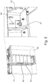
- Fig. 5 shows an exemplary rack 60 with all modules 80 that is attached to a main frame 70.
- the hammer-head screws 50 with nuts 51 are located on the left and right top of the main frame 70.
- the right-hand side of Fig. 5 depicts an enlarged view on this screw connection.
- the panels of the modules 80 may close the front side of the rack 60 preventing the access to the hammer-head screw 50 through the front side.
- the installation of a rack becomes impossible when the slots 90 to the left and right side are also filled up with equipped racks 60 in which case no access is possible from either side.
- a pre-strain unit for a T-bolt according to claim 1 or methods for releasing/assembling a rack of modules from/to a main frame.
- the dependent claims refer to further advantageous realizations of the pre-strain unit.
- the present invention relates a pre-strain unit for a T-bolt during a release process of two components connected by the T-bolt.
- the unit comprises: a slider, a frame for providing a linear guiding for the slider during the release process and means for pre-straining the slider the frame against a head of the T-bolt to keep, during the release process, at least a part of the T-bolt protruding from the two components (that were connected prior the release process).
- the T-bolt may comprise a threaded portion opposite to the head which is engageable with a nut to establish the connection between the two components.
- the slider comprise optionally a contact surface adapted to a shape or size of the head of the T-bolt to provide sufficient support.
- the frame further comprises two opposite guiding parts adapted to receive the head of the T-bolt there between to provide a guidance for the head of the T-bolt when straining the means for pre-straining.
- the means for pre-straining comprises at least one spring extending between the frame and the slider.
- the frame further comprises a mounting structure to mount the frame to at least one of the two components (e.g. the rack).
- the frame and/or the slider comprises a metal (or plastic; dependent on the expected load or stress and the desired lifetime) material.
- the present invention relates also to a rack for receiving multiple modules, which is configured to be mounted to a main frame.
- the rack comprises: a frame structure with at least one opening and a pre-strain unit as described before.
- the pre-strain unit is mounted or mountable to the frame structure at a position of the opening to get into contact with a T-bolt through the opening and to provide a pre-strain force on the T-bolt.
- the T-bolt is configured to provide the connection between the rack and the main frame.
- the present invention relates also to a method for releasing a rack, optionally filled with modules, from a main frame that are connected by a T-bolt.
- the rack includes a pre-strain unit as defined before to pre-strain the T-bolt.
- the method comprises:
- the present invention relates also to a method for assembling a rack of modules to a main frame which are to be connected by a T-bolt through an opening of the rack that includes a pre-strain unit as defined before to pre-strain the T-bolt.
- the method comprises:
- embodiments solve at least some of the above-mentioned problems by a T-bolt release unit which keeps a loosened T-bolt in place and provides mechanics that keeps the T-bolt in the screw hole while the rack is pulled out of a main frame compartment.
- the desired effect is achieved by the pre-straining mechanism that pre-strains the slider which in turn holds the T-bolt after loosening in a particular position.
- the T-bolt can be pushed into the mounting hole so that the rack can be pulled out or, vice-versa, can be inserted into a slot of the main frame. Therefore, the T-bolt protrudes out of the hole when the fully equipped rack has reached the end position after being pushed into the slot again. Since the T-bolt protrudes out of the hole, also a washer can be mounted easily, and the nut can grip correctly.
- Fig. 1 depicts an embodiment of the pre-strain unit for a T-bolt 50 during a release process of two components (not shown) connected by the T-bolt 50.
- the unit comprises: a slider 110, a frame 120 for providing a linear guiding for the slider 110 during the release process and means 130 for pre-straining the slider 110 in the frame 120 against a head 52 of the T-bolt 50 to keep, during the release process, at least a portion of the T-bolt 50 protruding from the two connected components.
- Fig. 1 further depicts the T-bolt 50 placed with its head 52 onto the slider 110 that pushes the T-bolt 50 in the vertical direction upward.
- the frame 120 comprises a mounting structure 125 with further screws extending through openings of the mounting structure 125 so that the frame 120 can be secured to the rack at a desired location.
- the means 130 for pre-straining are strong enough to keep the T-bolt 50 at an upper position as depicted in Fig. 1 .
- Fig. 2 shows the pre-strain unit from different sides, wherein the slider 110 is inserted into the frame 120 and exposes a contact surface 112 for contacting the head 52 of the T-bolt 50 after mounting the pre-strain unit to one of the two components.
- a corresponding a mounting structure 125 is provided.
- the means 130 for prestraining include two exemplary springs which, when pushing down the slider 110 via the T-bolt 50, are strained due to the linear movement of the slider 110 into the frame 120.
- the frame 120 comprises in the upper part two tongue-like extensions 122, 124 which - at least in one direction - are smaller than the body part of the frame 120 and provide a guiding for the slider 110.
- the mounting structure 125 can be adapted to the particular form of the rack and may comprise, for example, holes 126 to receive corresponding screws for mounting the pre-strain unit to an exemplary rack.
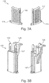
- Figs. 3A, 3B show enlarged pictures of the slider 110 and the frame 120.
- the slider 110 may comprise openings or lugs 114 for receiving the pre-strain means 130 (e.g., hooks of the springs).
- the slider 110 may be formed to minimize its weight while providing sufficient stability when pushing the T-bolt 50 together with the slider 110 in a vertical upward position.
- the slider 110 may comprise a plurality of holes or recesses 117 to lower the weight of the slider 110.
- the slider 110 may also be formed as a frame or as any kind of structure which is able to transfer the pre-strain force to the head 52 of the T-bolt 50.
- guiding parts 122, 124 protrude from the body portion to provide a guiding for the slider 110 when it is inserted into the frame 120.
- the guiding parts 122, 124 may comprise longitudinal grooves 127 which receive protruding parts 115 of the slider 110 (see Fig. 3A ).
- Fig. 4 shows an exemplary rack 60 with a frame structure 62 which is mounted onto a main frame 70 by using a plurality of T-bolts 50 which are pre-strained by the installed pre-strain unit according to embodiments of the present invention.
- the rack 60 and the main frame 70 may be formed as in Fig. 5 and represent examples of the two components that are connected by the T-bolts 50.
- the right-hand side in Fig. 4 depicts an enlarged view on an area where the T-bolt 50 connects the rack 60 with the main frame 70.
- the T-bolts 50 extend through openings 63 of the frame structure 62 and are secured with nuts 51 and optional washers to mount the frame structure 62 to the main frame 70.
- the depicted rack 60 is shown from a rear side which is typically not accessible when the main frame 70 is installed at a wall resulting in the initially mentioned problem that, during a release process, the T-bolt 50 may fall down if no pre-strain unit is installed. This may not only cause damage to installed modules 80 but may make it impossible to re-install a new T-bolt, e.g. when inserting the rack 60 into a free slot.
- Fig. 4 likewise illustrates the process of releasing/assembling a rack 60 from/to the main frame 70, which is significantly simplified when the pre-strain unit is installed in or at the rack 60. Firstly, if the nut 51 loosens the T-bolt 50 it can be pushed into the hole of the main frame 70. Simultaneously, the slider 110 will be pushed down and the spring(s) 130 of the pre-strain unit will be loaded. If the upper tip of the T-bolt 50 has reached an upper level 61 of the rack 60, the rack 60 can be pulled out of the main frame 70.
- the frame 120 of the pre-strain unit holds the T-bolt 50 (it may be closed, e.g.), the T-bolt 50 cannot be lost while moving the rack 60 out of the main frame 70. Therefore, any damages caused by a falling the T-bolt 50 is prevented when using embodiments of the present invention.
- the process can be performed in the opposite direction.
- the T-bolt 50 is pushed down until the upper tip is equal to the top 61 of the rack 60.
- the rack 50 is inserted or slip into a shelter of the main frame 70 and pushed to the end position.
- the T-bolt 50 will be pushed upward because of the loaded spring(s) 130 of the pre-strain unit. Therefore, it will pop out over the main frame hole so that washers and the nut 51 can be installed easily.
Landscapes
- Engineering & Computer Science (AREA)
- Microelectronics & Electronic Packaging (AREA)
- Mechanical Engineering (AREA)
- Connection Of Plates (AREA)
Claims (8)
- Vorspanneinheit für eine T-Nutenschraube (50) während eines Freigabevorgangs von zwei Komponenten (60, 70), die durch die T-Nutenschraube (50) verbunden sind, wobei die Einheit umfasst:einen Schieber (110);einen Rahmen (120) zum Bereitstellen einer linearen Führung für den Schieber (110) während des Freigabevorgangs; undMittel (130) zum Vorspannen des Schiebers (110) in dem Rahmen (120) gegen einen Kopf (52) der T-Nutenschraube (50), um während des Freigabevorgangs wenigstens einen Teil der T-Nutenschraube (50) aus den beiden Komponenten (60, 70) herausragend zu halten,dadurch gekennzeichnet, dassder Rahmen (120) ferner zwei gegenüberliegende Führungsteile (122, 124) umfasst, die angepasst sind, um den Kopf (52) der T-Nutenschraube (50) dazwischen aufzunehmen, um eine Führung für den Kopf (52) der T-Nutenschraube (50) bereitzustellen, wenn die Mittel (130) zum Vorspannen gespannt werden.
- Einheit nach Anspruch 1, wobei der Schieber (110) eine Berührungsoberfläche (112) umfasst, die an eine Form oder Größe des Kopfs (52) der T-Nutenschraube angepasst ist.
- Einheit nach einem der vorhergehenden Ansprüche, wobei die Mittel (130) zum Vorspannen wenigstens eine Feder umfassen, die sich zwischen dem Rahmen (120) und dem Schieber (110) erstreckt.
- Einheit nach einem der vorhergehenden Ansprüche, wobei der Rahmen (120) ferner eine Montagestruktur (125) umfasst, um den Rahmen (120) an wenigstens eine der zwei Komponenten (60, 70) zu montieren.
- Einheit nach einem der vorhergehenden Ansprüche, wobei der Rahmen (120) und/oder der Schieber (110) ein Metallmaterial umfassen.
- Gestell (60) zum Aufnehmen mehrerer Module (80), und das konfiguriert ist, um an einen Hauptrahmen (70) montiert zu sein, wobei das Gestell (60) umfasst:eine Rahmenstruktur (62) mit wenigstens einer Öffnung (63); undeine Vorspanneinheit nach einem der vorhergehenden Ansprüche, die an die Rahmenstruktur (62) an einer Position der Öffnung (63) montierbar ist, um eine T-Nutenschraube (50) durch die Öffnung (63) aufzunehmen und eine Vorspannkraft an die T-Nutenschraube (50) bereitzustellen, wobei die T-Nutenschraube (50) konfiguriert ist, um die Verbindung zwischen dem Gestell (60) und dem Hauptrahmen (70) bereitzustellen.
- Verfahren zum Freigeben eines Gestells (60) von Modulen (80) von einem Hauptrahmen (70), die durch eine T-Nutenschraube (50) durch eine Öffnung (63) des Gestells (60) verbunden sind, das eine Vorspanneinheit nach einem der Ansprüche 1-5 beinhaltet, um die T-Nutenschraube (50) vorzuspannen, wobei das Verfahren umfasst:Freigeben einer Mutter (51) von der T-Nutenschraube (50);Herunterdrücken der T-Nutenschraube (50) in die Öffnung (63) des Gestells (60) während eines Bewegens des Schiebers (110) in eine gespannte Position; undHerausziehen des Gestells (60) aus dem Hauptrahmen (70) während eines wenigstens vorübergehenden Haltens der T-Nutenschraube (50) in der gespannten Position.
- Verfahren zum Zusammensetzen eines Gestells (60) von Modulen (80) an einen Hauptrahmen (70), die durch eine T-Nutenschraube (50) durch eine Öffnung (63) des Gestells (60) verbunden werden sollen, das eine Vorspanneinheit nach einem der Ansprüche 1 bis 5 beinhaltet, um die T-Nutenschraube (50) vorzuspannen, wobei das Verfahren umfasst:Herunterdrücken der T-Nutenschraube (50) in die Öffnung (63) des Gestells (60) während des Bewegens des Schiebers (110) in eine gespannte Position;Bewegen des Gestells (60) zu dem Hauptrahmen (70) während des wenigstens vorübergehenden Haltens der T-Nutenschraube (50) in der gespannten Position; und Befestigen der T-Nutenschraube (50) durch eine Mutter (51).
Priority Applications (3)
| Application Number | Priority Date | Filing Date | Title |
|---|---|---|---|
| EP18169635.2A EP3562287B1 (de) | 2018-04-26 | 2018-04-26 | Vorspanneinheit für einen t-bolzen |
| CA3039996A CA3039996C (en) | 2018-04-26 | 2019-04-10 | Pre-strain unit for a t-bolt |
| US16/395,040 US11147178B2 (en) | 2018-04-26 | 2019-04-25 | Pre-strain unit for a T-bolt |
Applications Claiming Priority (1)
| Application Number | Priority Date | Filing Date | Title |
|---|---|---|---|
| EP18169635.2A EP3562287B1 (de) | 2018-04-26 | 2018-04-26 | Vorspanneinheit für einen t-bolzen |
Publications (2)
| Publication Number | Publication Date |
|---|---|
| EP3562287A1 EP3562287A1 (de) | 2019-10-30 |
| EP3562287B1 true EP3562287B1 (de) | 2021-02-24 |
Family
ID=62110869
Family Applications (1)
| Application Number | Title | Priority Date | Filing Date |
|---|---|---|---|
| EP18169635.2A Active EP3562287B1 (de) | 2018-04-26 | 2018-04-26 | Vorspanneinheit für einen t-bolzen |
Country Status (3)
| Country | Link |
|---|---|
| US (1) | US11147178B2 (de) |
| EP (1) | EP3562287B1 (de) |
| CA (1) | CA3039996C (de) |
Family Cites Families (5)
| Publication number | Priority date | Publication date | Assignee | Title |
|---|---|---|---|---|
| US1428138A (en) * | 1920-01-20 | 1922-09-05 | Silent Drama Syndicate | Magazine and magazine attachment for kinetographs |
| JPS59118027U (ja) * | 1983-01-26 | 1984-08-09 | 松下電器産業株式会社 | 結合装置 |
| US7795532B2 (en) * | 2006-03-13 | 2010-09-14 | Panduit Corp. | Network Cabinet |
| US7796377B2 (en) * | 2008-12-08 | 2010-09-14 | Oracle America, Inc. | Computer component ejector mechanism |
| US10097133B2 (en) * | 2016-04-14 | 2018-10-09 | Shahriar Shamloo Aliabadi | Racking system for installing solar panels |
-
2018
- 2018-04-26 EP EP18169635.2A patent/EP3562287B1/de active Active
-
2019
- 2019-04-10 CA CA3039996A patent/CA3039996C/en active Active
- 2019-04-25 US US16/395,040 patent/US11147178B2/en active Active
Non-Patent Citations (1)
| Title |
|---|
| None * |
Also Published As
| Publication number | Publication date |
|---|---|
| EP3562287A1 (de) | 2019-10-30 |
| US20190335602A1 (en) | 2019-10-31 |
| US11147178B2 (en) | 2021-10-12 |
| CA3039996C (en) | 2024-02-20 |
| CA3039996A1 (en) | 2019-10-26 |
Similar Documents
| Publication | Publication Date | Title |
|---|---|---|
| US6891727B2 (en) | Apparatus and system to mount a device to a rack | |
| US7992950B2 (en) | Method for installing a slide assembly for a computer server using dual flat springs | |
| US6629614B2 (en) | Mounting for telecommunications equipment | |
| EP2526746B1 (de) | Keilbasierter leiterplattenrückhalter | |
| US6622873B2 (en) | Self-aligning, single person installable rack rail/alignment plate assembly | |
| US6435354B1 (en) | Cable management arm assembly | |
| US6138839A (en) | Pivoted latching bar for retaining expansion cards | |
| EP3157315B1 (de) | Serverracksystem für montageausrüstung | |
| EP2395826A1 (de) | Fixierglied, verbindeplatte und gehäuse und verfahren zum fixieren einer verbindeplatte | |
| US20190021183A1 (en) | Equipment clamping assembly having horizontal and vertical clamps for use in rugged and other environments | |
| US6626300B2 (en) | Rack assembly that does not require tools for coupling chassis to slide | |
| EP0971572A1 (de) | Befestigungmechanismus für eine Zweikomponentige Vorrichtung | |
| US11147178B2 (en) | Pre-strain unit for a T-bolt | |
| US9538682B1 (en) | Strengthening electronic equipment | |
| WO2009105068A1 (en) | Mounting assembly for rack equipment | |
| US9240626B2 (en) | Snap attachment for reflector mounting | |
| US11577586B2 (en) | Collapsible side door latch module | |
| EP3329570A1 (de) | Kabelverwaltungsanordnung für gestellmontierte ausrüstung | |
| US20080049385A1 (en) | Apparatus and method for automatically securing a chassis to a rackmount rail | |
| JP6881849B2 (ja) | 電子機器支持フレーム及び電子機器におけるケーブル支持方法 | |
| CN221202911U (zh) | 一种电气机箱 | |
| CN218971732U (zh) | 一种便于安装的电子元件 | |
| CN217656263U (zh) | 一种配电箱用便于调整的安装架 | |
| CN118867923B (zh) | 一种组合式母线槽及其组装方法 | |
| CN224215010U (zh) | 一种治安监控安装用固定架 |
Legal Events
| Date | Code | Title | Description |
|---|---|---|---|
| PUAI | Public reference made under article 153(3) epc to a published international application that has entered the european phase |
Free format text: ORIGINAL CODE: 0009012 |
|
| STAA | Information on the status of an ep patent application or granted ep patent |
Free format text: STATUS: REQUEST FOR EXAMINATION WAS MADE |
|
| 17P | Request for examination filed |
Effective date: 20190430 |
|
| AK | Designated contracting states |
Kind code of ref document: A1 Designated state(s): AL AT BE BG CH CY CZ DE DK EE ES FI FR GB GR HR HU IE IS IT LI LT LU LV MC MK MT NL NO PL PT RO RS SE SI SK SM TR |
|
| AX | Request for extension of the european patent |
Extension state: BA ME |
|
| REG | Reference to a national code |
Ref country code: DE Ref legal event code: R079 Ref document number: 602018012874 Country of ref document: DE Free format text: PREVIOUS MAIN CLASS: H05K0007140000 Ipc: H05K0007180000 |
|
| GRAP | Despatch of communication of intention to grant a patent |
Free format text: ORIGINAL CODE: EPIDOSNIGR1 |
|
| STAA | Information on the status of an ep patent application or granted ep patent |
Free format text: STATUS: GRANT OF PATENT IS INTENDED |
|
| RIC1 | Information provided on ipc code assigned before grant |
Ipc: H02B 1/36 20060101ALI20200825BHEP Ipc: H05K 7/18 20060101AFI20200825BHEP |
|
| RIC1 | Information provided on ipc code assigned before grant |
Ipc: H05K 7/18 20060101AFI20200828BHEP |
|
| INTG | Intention to grant announced |
Effective date: 20200922 |
|
| GRAS | Grant fee paid |
Free format text: ORIGINAL CODE: EPIDOSNIGR3 |
|
| GRAA | (expected) grant |
Free format text: ORIGINAL CODE: 0009210 |
|
| STAA | Information on the status of an ep patent application or granted ep patent |
Free format text: STATUS: THE PATENT HAS BEEN GRANTED |
|
| AK | Designated contracting states |
Kind code of ref document: B1 Designated state(s): AL AT BE BG CH CY CZ DE DK EE ES FI FR GB GR HR HU IE IS IT LI LT LU LV MC MK MT NL NO PL PT RO RS SE SI SK SM TR |
|
| REG | Reference to a national code |
Ref country code: CH Ref legal event code: EP |
|
| REG | Reference to a national code |
Ref country code: AT Ref legal event code: REF Ref document number: 1366137 Country of ref document: AT Kind code of ref document: T Effective date: 20210315 |
|
| REG | Reference to a national code |
Ref country code: IE Ref legal event code: FG4D |
|
| REG | Reference to a national code |
Ref country code: DE Ref legal event code: R096 Ref document number: 602018012874 Country of ref document: DE |
|
| REG | Reference to a national code |
Ref country code: LT Ref legal event code: MG9D |
|
| REG | Reference to a national code |
Ref country code: NL Ref legal event code: MP Effective date: 20210224 |
|
| PG25 | Lapsed in a contracting state [announced via postgrant information from national office to epo] |
Ref country code: BG Free format text: LAPSE BECAUSE OF FAILURE TO SUBMIT A TRANSLATION OF THE DESCRIPTION OR TO PAY THE FEE WITHIN THE PRESCRIBED TIME-LIMIT Effective date: 20210524 Ref country code: GR Free format text: LAPSE BECAUSE OF FAILURE TO SUBMIT A TRANSLATION OF THE DESCRIPTION OR TO PAY THE FEE WITHIN THE PRESCRIBED TIME-LIMIT Effective date: 20210525 Ref country code: HR Free format text: LAPSE BECAUSE OF FAILURE TO SUBMIT A TRANSLATION OF THE DESCRIPTION OR TO PAY THE FEE WITHIN THE PRESCRIBED TIME-LIMIT Effective date: 20210224 Ref country code: FI Free format text: LAPSE BECAUSE OF FAILURE TO SUBMIT A TRANSLATION OF THE DESCRIPTION OR TO PAY THE FEE WITHIN THE PRESCRIBED TIME-LIMIT Effective date: 20210224 Ref country code: NO Free format text: LAPSE BECAUSE OF FAILURE TO SUBMIT A TRANSLATION OF THE DESCRIPTION OR TO PAY THE FEE WITHIN THE PRESCRIBED TIME-LIMIT Effective date: 20210524 Ref country code: PT Free format text: LAPSE BECAUSE OF FAILURE TO SUBMIT A TRANSLATION OF THE DESCRIPTION OR TO PAY THE FEE WITHIN THE PRESCRIBED TIME-LIMIT Effective date: 20210624 Ref country code: LT Free format text: LAPSE BECAUSE OF FAILURE TO SUBMIT A TRANSLATION OF THE DESCRIPTION OR TO PAY THE FEE WITHIN THE PRESCRIBED TIME-LIMIT Effective date: 20210224 |
|
| REG | Reference to a national code |
Ref country code: AT Ref legal event code: MK05 Ref document number: 1366137 Country of ref document: AT Kind code of ref document: T Effective date: 20210224 |
|
| PG25 | Lapsed in a contracting state [announced via postgrant information from national office to epo] |
Ref country code: SE Free format text: LAPSE BECAUSE OF FAILURE TO SUBMIT A TRANSLATION OF THE DESCRIPTION OR TO PAY THE FEE WITHIN THE PRESCRIBED TIME-LIMIT Effective date: 20210224 Ref country code: PL Free format text: LAPSE BECAUSE OF FAILURE TO SUBMIT A TRANSLATION OF THE DESCRIPTION OR TO PAY THE FEE WITHIN THE PRESCRIBED TIME-LIMIT Effective date: 20210224 Ref country code: NL Free format text: LAPSE BECAUSE OF FAILURE TO SUBMIT A TRANSLATION OF THE DESCRIPTION OR TO PAY THE FEE WITHIN THE PRESCRIBED TIME-LIMIT Effective date: 20210224 Ref country code: RS Free format text: LAPSE BECAUSE OF FAILURE TO SUBMIT A TRANSLATION OF THE DESCRIPTION OR TO PAY THE FEE WITHIN THE PRESCRIBED TIME-LIMIT Effective date: 20210224 Ref country code: LV Free format text: LAPSE BECAUSE OF FAILURE TO SUBMIT A TRANSLATION OF THE DESCRIPTION OR TO PAY THE FEE WITHIN THE PRESCRIBED TIME-LIMIT Effective date: 20210224 |
|
| PG25 | Lapsed in a contracting state [announced via postgrant information from national office to epo] |
Ref country code: IS Free format text: LAPSE BECAUSE OF FAILURE TO SUBMIT A TRANSLATION OF THE DESCRIPTION OR TO PAY THE FEE WITHIN THE PRESCRIBED TIME-LIMIT Effective date: 20210624 |
|
| PG25 | Lapsed in a contracting state [announced via postgrant information from national office to epo] |
Ref country code: AT Free format text: LAPSE BECAUSE OF FAILURE TO SUBMIT A TRANSLATION OF THE DESCRIPTION OR TO PAY THE FEE WITHIN THE PRESCRIBED TIME-LIMIT Effective date: 20210224 Ref country code: SM Free format text: LAPSE BECAUSE OF FAILURE TO SUBMIT A TRANSLATION OF THE DESCRIPTION OR TO PAY THE FEE WITHIN THE PRESCRIBED TIME-LIMIT Effective date: 20210224 Ref country code: CZ Free format text: LAPSE BECAUSE OF FAILURE TO SUBMIT A TRANSLATION OF THE DESCRIPTION OR TO PAY THE FEE WITHIN THE PRESCRIBED TIME-LIMIT Effective date: 20210224 Ref country code: EE Free format text: LAPSE BECAUSE OF FAILURE TO SUBMIT A TRANSLATION OF THE DESCRIPTION OR TO PAY THE FEE WITHIN THE PRESCRIBED TIME-LIMIT Effective date: 20210224 |
|
| REG | Reference to a national code |
Ref country code: DE Ref legal event code: R097 Ref document number: 602018012874 Country of ref document: DE |
|
| PG25 | Lapsed in a contracting state [announced via postgrant information from national office to epo] |
Ref country code: MC Free format text: LAPSE BECAUSE OF FAILURE TO SUBMIT A TRANSLATION OF THE DESCRIPTION OR TO PAY THE FEE WITHIN THE PRESCRIBED TIME-LIMIT Effective date: 20210224 Ref country code: DK Free format text: LAPSE BECAUSE OF FAILURE TO SUBMIT A TRANSLATION OF THE DESCRIPTION OR TO PAY THE FEE WITHIN THE PRESCRIBED TIME-LIMIT Effective date: 20210224 Ref country code: SK Free format text: LAPSE BECAUSE OF FAILURE TO SUBMIT A TRANSLATION OF THE DESCRIPTION OR TO PAY THE FEE WITHIN THE PRESCRIBED TIME-LIMIT Effective date: 20210224 Ref country code: RO Free format text: LAPSE BECAUSE OF FAILURE TO SUBMIT A TRANSLATION OF THE DESCRIPTION OR TO PAY THE FEE WITHIN THE PRESCRIBED TIME-LIMIT Effective date: 20210224 |
|
| PG25 | Lapsed in a contracting state [announced via postgrant information from national office to epo] |
Ref country code: LU Free format text: LAPSE BECAUSE OF NON-PAYMENT OF DUE FEES Effective date: 20210426 |
|
| PLBE | No opposition filed within time limit |
Free format text: ORIGINAL CODE: 0009261 |
|
| STAA | Information on the status of an ep patent application or granted ep patent |
Free format text: STATUS: NO OPPOSITION FILED WITHIN TIME LIMIT |
|
| REG | Reference to a national code |
Ref country code: BE Ref legal event code: MM Effective date: 20210430 |
|
| PG25 | Lapsed in a contracting state [announced via postgrant information from national office to epo] |
Ref country code: ES Free format text: LAPSE BECAUSE OF FAILURE TO SUBMIT A TRANSLATION OF THE DESCRIPTION OR TO PAY THE FEE WITHIN THE PRESCRIBED TIME-LIMIT Effective date: 20210224 Ref country code: CH Free format text: LAPSE BECAUSE OF NON-PAYMENT OF DUE FEES Effective date: 20210430 Ref country code: AL Free format text: LAPSE BECAUSE OF FAILURE TO SUBMIT A TRANSLATION OF THE DESCRIPTION OR TO PAY THE FEE WITHIN THE PRESCRIBED TIME-LIMIT Effective date: 20210224 Ref country code: LI Free format text: LAPSE BECAUSE OF NON-PAYMENT OF DUE FEES Effective date: 20210430 |
|
| 26N | No opposition filed |
Effective date: 20211125 |
|
| PG25 | Lapsed in a contracting state [announced via postgrant information from national office to epo] |
Ref country code: SI Free format text: LAPSE BECAUSE OF FAILURE TO SUBMIT A TRANSLATION OF THE DESCRIPTION OR TO PAY THE FEE WITHIN THE PRESCRIBED TIME-LIMIT Effective date: 20210224 |
|
| PG25 | Lapsed in a contracting state [announced via postgrant information from national office to epo] |
Ref country code: IT Free format text: LAPSE BECAUSE OF FAILURE TO SUBMIT A TRANSLATION OF THE DESCRIPTION OR TO PAY THE FEE WITHIN THE PRESCRIBED TIME-LIMIT Effective date: 20210224 Ref country code: IE Free format text: LAPSE BECAUSE OF NON-PAYMENT OF DUE FEES Effective date: 20210426 |
|
| PG25 | Lapsed in a contracting state [announced via postgrant information from national office to epo] |
Ref country code: IS Free format text: LAPSE BECAUSE OF FAILURE TO SUBMIT A TRANSLATION OF THE DESCRIPTION OR TO PAY THE FEE WITHIN THE PRESCRIBED TIME-LIMIT Effective date: 20210624 |
|
| PG25 | Lapsed in a contracting state [announced via postgrant information from national office to epo] |
Ref country code: BE Free format text: LAPSE BECAUSE OF NON-PAYMENT OF DUE FEES Effective date: 20210430 |
|
| PG25 | Lapsed in a contracting state [announced via postgrant information from national office to epo] |
Ref country code: CY Free format text: LAPSE BECAUSE OF FAILURE TO SUBMIT A TRANSLATION OF THE DESCRIPTION OR TO PAY THE FEE WITHIN THE PRESCRIBED TIME-LIMIT Effective date: 20210224 |
|
| PG25 | Lapsed in a contracting state [announced via postgrant information from national office to epo] |
Ref country code: HU Free format text: LAPSE BECAUSE OF FAILURE TO SUBMIT A TRANSLATION OF THE DESCRIPTION OR TO PAY THE FEE WITHIN THE PRESCRIBED TIME-LIMIT; INVALID AB INITIO Effective date: 20180426 |
|
| PG25 | Lapsed in a contracting state [announced via postgrant information from national office to epo] |
Ref country code: MK Free format text: LAPSE BECAUSE OF FAILURE TO SUBMIT A TRANSLATION OF THE DESCRIPTION OR TO PAY THE FEE WITHIN THE PRESCRIBED TIME-LIMIT Effective date: 20210224 |
|
| PG25 | Lapsed in a contracting state [announced via postgrant information from national office to epo] |
Ref country code: MT Free format text: LAPSE BECAUSE OF FAILURE TO SUBMIT A TRANSLATION OF THE DESCRIPTION OR TO PAY THE FEE WITHIN THE PRESCRIBED TIME-LIMIT Effective date: 20210224 |
|
| PGFP | Annual fee paid to national office [announced via postgrant information from national office to epo] |
Ref country code: DE Payment date: 20250417 Year of fee payment: 8 |
|
| PGFP | Annual fee paid to national office [announced via postgrant information from national office to epo] |
Ref country code: FR Payment date: 20250422 Year of fee payment: 8 |
|
| PG25 | Lapsed in a contracting state [announced via postgrant information from national office to epo] |
Ref country code: TR Free format text: LAPSE BECAUSE OF FAILURE TO SUBMIT A TRANSLATION OF THE DESCRIPTION OR TO PAY THE FEE WITHIN THE PRESCRIBED TIME-LIMIT Effective date: 20210224 |
|
| PGFP | Annual fee paid to national office [announced via postgrant information from national office to epo] |
Ref country code: GB Payment date: 20260324 Year of fee payment: 9 |