EP3561942A1 - Method for regenerating battery cell - Google Patents
Method for regenerating battery cell Download PDFInfo
- Publication number
- EP3561942A1 EP3561942A1 EP18870993.5A EP18870993A EP3561942A1 EP 3561942 A1 EP3561942 A1 EP 3561942A1 EP 18870993 A EP18870993 A EP 18870993A EP 3561942 A1 EP3561942 A1 EP 3561942A1
- Authority
- EP
- European Patent Office
- Prior art keywords
- battery cell
- rays
- product
- negative electrode
- radiant rays
- Prior art date
- Legal status (The legal status is an assumption and is not a legal conclusion. Google has not performed a legal analysis and makes no representation as to the accuracy of the status listed.)
- Granted
Links
Images


Classifications
-
- H—ELECTRICITY
- H01—ELECTRIC ELEMENTS
- H01M—PROCESSES OR MEANS, e.g. BATTERIES, FOR THE DIRECT CONVERSION OF CHEMICAL ENERGY INTO ELECTRICAL ENERGY
- H01M10/00—Secondary cells; Manufacture thereof
- H01M10/42—Methods or arrangements for servicing or maintenance of secondary cells or secondary half-cells
- H01M10/4242—Regeneration of electrolyte or reactants
-
- B—PERFORMING OPERATIONS; TRANSPORTING
- B08—CLEANING
- B08B—CLEANING IN GENERAL; PREVENTION OF FOULING IN GENERAL
- B08B7/00—Cleaning by methods not provided for in a single other subclass or a single group in this subclass
-
- B—PERFORMING OPERATIONS; TRANSPORTING
- B08—CLEANING
- B08B—CLEANING IN GENERAL; PREVENTION OF FOULING IN GENERAL
- B08B7/00—Cleaning by methods not provided for in a single other subclass or a single group in this subclass
- B08B7/0035—Cleaning by methods not provided for in a single other subclass or a single group in this subclass by radiant energy, e.g. UV, laser, light beam or the like
-
- H—ELECTRICITY
- H01—ELECTRIC ELEMENTS
- H01M—PROCESSES OR MEANS, e.g. BATTERIES, FOR THE DIRECT CONVERSION OF CHEMICAL ENERGY INTO ELECTRICAL ENERGY
- H01M10/00—Secondary cells; Manufacture thereof
- H01M10/42—Methods or arrangements for servicing or maintenance of secondary cells or secondary half-cells
-
- Y—GENERAL TAGGING OF NEW TECHNOLOGICAL DEVELOPMENTS; GENERAL TAGGING OF CROSS-SECTIONAL TECHNOLOGIES SPANNING OVER SEVERAL SECTIONS OF THE IPC; TECHNICAL SUBJECTS COVERED BY FORMER USPC CROSS-REFERENCE ART COLLECTIONS [XRACs] AND DIGESTS
- Y02—TECHNOLOGIES OR APPLICATIONS FOR MITIGATION OR ADAPTATION AGAINST CLIMATE CHANGE
- Y02E—REDUCTION OF GREENHOUSE GAS [GHG] EMISSIONS, RELATED TO ENERGY GENERATION, TRANSMISSION OR DISTRIBUTION
- Y02E60/00—Enabling technologies; Technologies with a potential or indirect contribution to GHG emissions mitigation
- Y02E60/10—Energy storage using batteries
-
- Y—GENERAL TAGGING OF NEW TECHNOLOGICAL DEVELOPMENTS; GENERAL TAGGING OF CROSS-SECTIONAL TECHNOLOGIES SPANNING OVER SEVERAL SECTIONS OF THE IPC; TECHNICAL SUBJECTS COVERED BY FORMER USPC CROSS-REFERENCE ART COLLECTIONS [XRACs] AND DIGESTS
- Y02—TECHNOLOGIES OR APPLICATIONS FOR MITIGATION OR ADAPTATION AGAINST CLIMATE CHANGE
- Y02W—CLIMATE CHANGE MITIGATION TECHNOLOGIES RELATED TO WASTEWATER TREATMENT OR WASTE MANAGEMENT
- Y02W30/00—Technologies for solid waste management
- Y02W30/50—Reuse, recycling or recovery technologies
- Y02W30/84—Recycling of batteries or fuel cells
Definitions
- the present invention relates to a battery cell regeneration method, and more particularly, to a lithium ion non-destructive regeneration method using a high capacity radiation ray.
- a secondary battery refers to a battery that can be used semi-permanently by charging electric current generated by a process in which an electric current supplied from an external power source causes an oxidation or reduction reaction of a substance between a positive electrode and a negative electrode.
- a primary battery has many disadvantages that it cannot be reused, and the cost of disposing of or recycling the battery is large, but the secondary battery has an advantage that it can be charged multiple times.
- the secondary battery can be classified into a nickel battery, a lithium ion battery, a polymer battery, and a lithium polymer battery depending on what is used as a filling material.
- the lithium ion battery has been widely used in the rechargeable battery market due to the recent miniaturization and weight reduction of electronic equipment and the generalization of use of portable electronic devices.
- the lithium ion battery is manufactured by using a material capable of inserting and desorbing lithium ions as a negative electrode portion and a positive electrode portion and filling an organic electrolyte or a polymer electrolyte between the positive electrode portion and the negative electrode portion, and electric energy is generated by an oxidation and reduction reaction when the lithium ions are inserted and desorbed from the positive electrode portion and the negative electrode portion.
- Lithium rechargeable batteries are being used in a wide variety of products ranging from small-capacity mobile phone batteries to large-capacity electric vehicle batteries because they are light-weight and advantageous in making high capacity batteries.
- Embodiments relate to a method of simply regenerating a battery cell without disassembling the battery cell.
- a method of regenerating a battery cell includes: inserting the battery cell into a magnetic resonance imaging device; measuring a location of a by-product formed in the battery cell using the magnetic resonance imaging device; and ionizing a material contained in the by-product by irradiating radiant rays by targeting the by-product at the measured location.
- the radiant rays may be irradiated until a value of energy that passes through a battery cell having reached an end of life reaches a value of energy that passes through an initial battery cell.
- a linear particle accelerator may be used to irradiate the radiant rays.
- a robotic arm connected to the linear particle accelerator may be used to target the by-product.
- the radiant rays may be irradiated using a collimator included in the linear particle accelerator.
- the collimator may be formed of tungsten or lead.
- the radiant rays may be one selected from X-rays, gamma rays, beta rays, visible rays, and infrared rays.
- the by-product may be a lithium metal material formed between a negative electrode and a separator.
- the ionizing of the material contained in the by-product may include irradiating the radiant rays in a direction parallel to a surface of the negative electrode.
- high dose radiation may be used to ionize the plated lithium metal on the negative electrode surface to convert it to available lithium.
- the by-product may be removed without changing the internal structure of the battery by specifying the location of the by-product to be irradiated using a magnetic resonance imaging device before irradiation of radiant rays.
- FIGS. 1 to 5 are schematic views showing a method of regenerating a battery cell according to an embodiment of the present invention.
- a portion such as a layer, a film, an area, a plate, etc.
- a part when a part is “directly over” another part, it means that there is no other part in the middle.
- a reference portion means to be disposed above or below the reference portion and does not necessarily mean to be “on” toward the opposite direction of gravity.
- FIGS. 1 to 5 are schematic views showing a method of regenerating a battery cell according to an embodiment of the present invention.
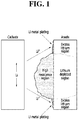
- FIG. 1 is a schematic view showing a by-product formed on an electrode surface.
- by-products such as lithium metal are formed around the negative electrode during charging of the lithium ion battery.
- the by-product refers to lithium ions that are precipitated as lithium plating without being inserted into the layered structure of the negative electrode during the charging of the battery.
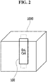
- FIG. 2 is a schematic view illustrating a battery cell inserted into a magnetic resonance imaging device according to an embodiment of the present invention.
- the battery cell 100 may be disposed in a magnetic resonance imaging device 1000 to accurately measure the location of a by-product formed in the battery.
- the location of the lithium metal formed between the separator and the negative electrode is imaged to allow the position setting to be performed at the time of the subsequent irradiation of radiant rays.
- the battery cell 1 00 disposed in the magnetic resonance imaging device 1000 uses a battery cell in which rapid capacity degradation occurs as the lifespan thereof approaches the end of life (EoL).
- FIG. 3 is a view showing an electrode assembly 101 included in the battery cell described with reference to FIG. 2 .
- an electrode assembly includes a positive electrode 110, a negative electrode 120, and a separator 130 disposed therebetween.
- the separator 130 electrically isolates the positive electrode 110 and the negative electrode 120.
- the positive electrode 110 includes a positive electrode current collector 111 and a positive electrode active material layer 113 disposed between the positive electrode current collector 111 and the separator 130.
- the electrode assembly 101 is impregnated with the electrolyte 200 and may be enclosed by a case (not shown).
- the positive electrode current collector 111 can generally be made to have a thickness of 3 to 500 micrometers.
- the positive electrode current collector 111 is not particularly limited as long as it has high conductivity without causing chemical change in the battery including the electrode assembly according to the present embodiment.
- stainless steel, aluminum, nickel, titanium, fired carbon or aluminum or stainless steel with a surface treated with carbon, nickel, titanium, silver, or the like may be used.
- the positive electrode current collector 111 may include fine irregularities on the surface thereof to enhance the adhesion of the positive electrode active material and may have various forms such as a film, a sheet, a foil, a net, a porous body, a foam, and a nonwoven fabric.
- the positive electrode active material layer 113 is formed by applying a positive electrode material mixture that contains the positive electrode active material, a conductive material and a binder to the positive electrode current collector 111 except for a portion where a tab is to be formed, and drying and pressing. A filler may be further added to the mixture as necessary.
- the conductive material is usually added in an amount of 1 to 50% by weight based on the total weight of the mixture including the positive electrode active material.
- a conductive material is not particularly limited as long as it has electrical conductivity without causing a chemical change in the battery, and examples thereof include graphite such as natural graphite and artificial graphite; carbon black such as carbon black, acetylene black, Ketjen black, channel black, furnace black, lamp black, and summer black; conductive fibers such as carbon fiber and metal fiber; metal powders such as carbon fluoride, aluminum and nickel powder; conductive whisker such as zinc oxide and potassium titanate; conductive metal oxides such as titanium oxide; and conductive materials such as polyphenylene derivatives and the like.
- the binder is added in an amount of 1 to 50% by weight, with respect to the total weight of the mixture that contains the positive electrode active material, as a component that assists in bonding between the active material and the conductive material and bonding to the current collector.
- binders include polyvinylidene fluoride, polyvinyl alcohol, carboxymethylcellulose, starch, hydroxypropylcellulose, regenerated cellulose, polyvinylpyrrolidone, tetrafluoroethylene, polyethylene, polypropylene, ethylene-propylene-diene terpolymer, sulfonated ethyl-propylene-diene terpolymer, styrene butadiene rubber, fluorine rubber, and various copolymers.
- the filler is optionally used as a component for suppressing expansion of a positive electrode, and is not particularly limited as long as it is a fibrous material without causing chemical change in the battery using the electrode assembly according to the present embodiment.
- a fibrous material such as glass fiber and carbon fiber may be used.
- the negative electrode 120 includes a negative electrode current collector 121 and a negative electrode active material layer 123 positioned between the negative electrode current collector 121 and the separator 130.
- the negative electrode current collector 121 may be generally made to have a thickness of 3 to 500 micrometers.
- the negative electrode current collector 121 is not particularly limited as long as it has high conductivity without causing chemical change in the battery including the electrode assembly according to the present embodiment.
- copper, stainless steel, aluminum-cadmium alloys and the like may be used.
- fine unevenness can be formed on the surface to enhance the bonding force of the negative electrode active material.
- Various forms such as films, sheets, foils, nets, porous bodies, and foams are possible.
- the negative electrode active material layer 123 includes a negative electrode active material, and the negative electrode active material includes, for example, non-graphitizable carbon, carbon such as graphite carbon, metal complex oxides such as Li x FeO 3 (0 ⁇ x ⁇ 1), Li x WO 2 (0 ⁇ x ⁇ 1), Sn x Me 1-x Me' y O z (Me: Mn, Fe, Pb, Ge; Me': Al, B, P, Si, Group 1, Group 2 and Group 3 elements of the periodic table, halogen; 0 ⁇ x ⁇ 1; 1 ⁇ y ⁇ 3; 1 ⁇ z ⁇ 8), lithium metal, lithium alloys, silicon-based alloys, tin-based alloys, metal oxides such as SnO, SnO 2 , PbO, PbO 2 , Pb 2 O 3 , Sb 2 O 4 , Sb 2 O 5 , GeO, GeO 2 , Bi 2 O 3 , Bi 2 O 4 and Bi 2 O 5 , conductive polymers such as polyacetylene, and
- the negative electrode active material layer 123 is formed by applying a negative electrode material mixture that contains the negative electrode active material, a conductive material and a binder to the negative electrode current collector 121 except for a portion where a tab is to be formed, and drying and pressing. A filler may be further added to the mixture as necessary.
- the separator 130 may be formed of an insulating thin film having high ion permeability and mechanical strength.
- Examples of the separator 130 include olefin-based polymers such as polypropylene which is chemically resistant and hydrophobic; a sheet or a nonwoven fabric made of glass fiber, polyethylene or the like.
- the lithium-plated by-product 500 is formed on the surface of the negative electrode 120, and the accurate location of the by-product 500 is determined by referring to the image record and the like measured by the magnetic resonance imaging device described in FIG. 2 , and radiant rays 400 are irradiated through the location targeting.
- the radiant rays 400 may be selected from X-ray, gamma ray, beta ray, visible ray and infrared ray, and the radiant rays 400 are irradiated along a first direction which is parallel to the surface of the negative electrode 120.
- the lithium metal contained in the by-product 500 is ionized and converted into lithium ions that may be used for charging.
- FIG. 4 is a view for explaining energy of radiant rays irradiated to a by-product according to this embodiment.
- the capacity retention rate of the initial battery cell may be 100%, and the capacity retention rate of the battery cell having reached the end of life (EoL) may be 70% or less.
- the capacity retention rate may be a value obtained by dividing the discharge capacity by the initial discharge capacity.
- the capacity retention rate decreases as the number of charge and discharge cycles increases, and the definition of the initial battery cell and the battery cell whose life has ended is not necessarily limited to this, and it is merely an example for explaining the level of irradiating the radiant rays 400, and thus it is possible to modify the capacity retention rate for defining a battery cell whose lifetime has expired.
- FIG. 5 is a view showing a method of irradiating radiant rays in a battery cell regeneration method according to an embodiment of the present invention.
- a linear particle accelerator 600 may be used to generate radiant rays to irradiate radiant rays according to this embodiment.
- the linear particle accelerator 600 may be connected to a robotic arm 700 to accurately target the by-product.
- the collimator 800 may be mounted on the linear particle accelerator 600 to emit radiant rays while changing the opening of the radiant rays to match the shape of the by-product.
- the positive electrode is composed of a lithium metal oxide, but the negative electrode material of the battery may be a graphite having a stacked structure.
- the negative electrode material of the battery may be a graphite having a stacked structure.
- lithium ions are stored in this layer.
- lithium ions cannot be inserted into the negative electrode and can form lithium metal in the battery cell that has reached the end of life (EoL) condition.
- EoL end of life
- the secondary battery can be recovered to the original charging capacity of the newly released condition.
Landscapes
- Engineering & Computer Science (AREA)
- Manufacturing & Machinery (AREA)
- Chemical & Material Sciences (AREA)
- Chemical Kinetics & Catalysis (AREA)
- Electrochemistry (AREA)
- General Chemical & Material Sciences (AREA)
- Physics & Mathematics (AREA)
- Optics & Photonics (AREA)
- Secondary Cells (AREA)
- Battery Electrode And Active Subsutance (AREA)
Abstract
Description
- This application claims the benefit of priority based on Korean Patent Application No.
10-2017-0138672, filed on October 24, 2017 - The present invention relates to a battery cell regeneration method, and more particularly, to a lithium ion non-destructive regeneration method using a high capacity radiation ray.
- Generally, a secondary battery refers to a battery that can be used semi-permanently by charging electric current generated by a process in which an electric current supplied from an external power source causes an oxidation or reduction reaction of a substance between a positive electrode and a negative electrode.
- A primary battery has many disadvantages that it cannot be reused, and the cost of disposing of or recycling the battery is large, but the secondary battery has an advantage that it can be charged multiple times. The secondary battery can be classified into a nickel battery, a lithium ion battery, a polymer battery, and a lithium polymer battery depending on what is used as a filling material. In particular, the lithium ion battery has been widely used in the rechargeable battery market due to the recent miniaturization and weight reduction of electronic equipment and the generalization of use of portable electronic devices.
- The lithium ion battery is manufactured by using a material capable of inserting and desorbing lithium ions as a negative electrode portion and a positive electrode portion and filling an organic electrolyte or a polymer electrolyte between the positive electrode portion and the negative electrode portion, and electric energy is generated by an oxidation and reduction reaction when the lithium ions are inserted and desorbed from the positive electrode portion and the negative electrode portion. Lithium rechargeable batteries are being used in a wide variety of products ranging from small-capacity mobile phone batteries to large-capacity electric vehicle batteries because they are light-weight and advantageous in making high capacity batteries.
- However, a battery cell having reached the end of life (EoL) is exposed to rapid capacity degradation, which is largely caused by internal resistance increase due to gas generation by side reaction. Degraded battery cells are either disposed of or recycled, both of which cause economic losses. In order to solve this problem, reuse has been actively studied.
- As a reuse method, there exists a method of replenishing a lithium source by injecting a certain amount of electrolyte to modify it to be suitable for reuse, but the existing methods are largely injected using expensive equipment in a well-controlled environment and methods of making a hole in the battery cell body or cutting the terrace portion of the battery cell and injecting it are used, and thus it is difficult to actually apply the reuse method.
- Embodiments relate to a method of simply regenerating a battery cell without disassembling the battery cell.
- However, the problems to be solved by the embodiments of the present invention are not limited to the above-mentioned problems, but can be variously extended within the scope of the technical idea included in the present invention.
- A method of regenerating a battery cell according to an embodiment of the present invention includes: inserting the battery cell into a magnetic resonance imaging device; measuring a location of a by-product formed in the battery cell using the magnetic resonance imaging device; and ionizing a material contained in the by-product by irradiating radiant rays by targeting the by-product at the measured location.
- The radiant rays may be irradiated until a value of energy that passes through a battery cell having reached an end of life reaches a value of energy that passes through an initial battery cell.
- A linear particle accelerator may be used to irradiate the radiant rays.
- A robotic arm connected to the linear particle accelerator may be used to target the by-product.
- The radiant rays may be irradiated using a collimator included in the linear particle accelerator.
- The collimator may be formed of tungsten or lead.
- The radiant rays may be one selected from X-rays, gamma rays, beta rays, visible rays, and infrared rays.
- The by-product may be a lithium metal material formed between a negative electrode and a separator.
- The ionizing of the material contained in the by-product may include irradiating the radiant rays in a direction parallel to a surface of the negative electrode.
- According to embodiments, high dose radiation may be used to ionize the plated lithium metal on the negative electrode surface to convert it to available lithium.
- The by-product may be removed without changing the internal structure of the battery by specifying the location of the by-product to be irradiated using a magnetic resonance imaging device before irradiation of radiant rays.
-
FIGS. 1 to 5 are schematic views showing a method of regenerating a battery cell according to an embodiment of the present invention. - Hereinafter, embodiments of the present invention will be described in detail with reference to the accompanying drawings. The present invention may, however, be embodied in many different forms and should not be construed as limited to the embodiments set forth herein.
- In order to clearly illustrate the present invention, parts not related to the description are omitted, and the same or similar components are denoted by the same reference numerals throughout the specification.
- In addition, since the sizes and thicknesses of the respective components shown in the drawings are arbitrarily shown for convenience of explanation, the present invention is not necessarily limited to those shown in the drawings. In the drawings, the thicknesses are enlarged to clearly indicate layers and regions. In the drawings, for the convenience of explanation, the thicknesses of some layers and regions are exaggerated.
- In addition, when a portion such as a layer, a film, an area, a plate, etc. is referred to as being "on" another portion, this includes not only the case where the portion is "directly on" the another portion but also the case where further another portion is interposed therebetween. Conversely, when a part is "directly over" another part, it means that there is no other part in the middle. Further, to be "on" a reference portion means to be disposed above or below the reference portion and does not necessarily mean to be "on" toward the opposite direction of gravity.
- Throughout the specification, when an element is referred to as "including" an element, it is understood that the element may include other elements as well unless specifically stated otherwise.
-
FIGS. 1 to 5 are schematic views showing a method of regenerating a battery cell according to an embodiment of the present invention.FIG. 1 is a schematic view showing a by-product formed on an electrode surface. - Referring to
FIG. 1 , by-products such as lithium metal are formed around the negative electrode during charging of the lithium ion battery. In particular, the by-product refers to lithium ions that are precipitated as lithium plating without being inserted into the layered structure of the negative electrode during the charging of the battery. -
FIG. 2 is a schematic view illustrating a battery cell inserted into a magnetic resonance imaging device according to an embodiment of the present invention. - Referring to
FIG. 2 , thebattery cell 100 may be disposed in a magneticresonance imaging device 1000 to accurately measure the location of a by-product formed in the battery. In other words, the location of the lithium metal formed between the separator and the negative electrode is imaged to allow the position setting to be performed at the time of the subsequent irradiation of radiant rays. The battery cell 1 00 disposed in the magneticresonance imaging device 1000 uses a battery cell in which rapid capacity degradation occurs as the lifespan thereof approaches the end of life (EoL). -
FIG. 3 is a view showing anelectrode assembly 101 included in the battery cell described with reference toFIG. 2 . - Referring to
FIG. 3 , an electrode assembly according to an embodiment of the present invention includes apositive electrode 110, anegative electrode 120, and aseparator 130 disposed therebetween. Theseparator 130 electrically isolates thepositive electrode 110 and thenegative electrode 120. Thepositive electrode 110 includes a positive electrodecurrent collector 111 and a positive electrodeactive material layer 113 disposed between the positive electrodecurrent collector 111 and theseparator 130. Theelectrode assembly 101 is impregnated with theelectrolyte 200 and may be enclosed by a case (not shown). - The positive electrode
current collector 111 can generally be made to have a thickness of 3 to 500 micrometers. The positive electrodecurrent collector 111 is not particularly limited as long as it has high conductivity without causing chemical change in the battery including the electrode assembly according to the present embodiment. For example, stainless steel, aluminum, nickel, titanium, fired carbon or aluminum or stainless steel with a surface treated with carbon, nickel, titanium, silver, or the like may be used. The positive electrodecurrent collector 111 may include fine irregularities on the surface thereof to enhance the adhesion of the positive electrode active material and may have various forms such as a film, a sheet, a foil, a net, a porous body, a foam, and a nonwoven fabric. - The positive electrode
active material layer 113 includes a positive electrode active material, and the positive electrode active material is a layered compound such as lithium cobalt oxide (LiCoO2), lithium nickel oxide (LiNiO2), a compound substituted with one or more transition metals, lithium manganese oxides such as Li1+yMn2-yO4 (where y is 0 to 0.33), LiMnO3, LiMn2O3, and LiMnO2, lithium copper oxide (Li2CuO2), vanadium oxides such as LiV3O8, LiV3O4, V2O5, and Cu2V2O7, Ni site type lithium nickel oxides expressed as LiNi1-yMyO2 (where M is Co, Mn, Al, Cu, Fe, Mg, B or Ga and y is 0.01 to 0.3), lithium manganese composite oxides expressed as LiMn2-yMyO2 (where M = Co, Ni, Fe, Cr, Zn, or Ta; y = 0.01 to 0.1) or Li2Mn3MO8 (where M = Fe, Co, Ni, Cu, or Zn), LiMn2O4 in which part of Li has been substituted with alkaline earth metal ions, a disulfide compound, and Fe2(MnO4)3, but not limited thereto. - The positive electrode
active material layer 113 is formed by applying a positive electrode material mixture that contains the positive electrode active material, a conductive material and a binder to the positive electrodecurrent collector 111 except for a portion where a tab is to be formed, and drying and pressing. A filler may be further added to the mixture as necessary. - The conductive material is usually added in an amount of 1 to 50% by weight based on the total weight of the mixture including the positive electrode active material. Such a conductive material is not particularly limited as long as it has electrical conductivity without causing a chemical change in the battery, and examples thereof include graphite such as natural graphite and artificial graphite; carbon black such as carbon black, acetylene black, Ketjen black, channel black, furnace black, lamp black, and summer black; conductive fibers such as carbon fiber and metal fiber; metal powders such as carbon fluoride, aluminum and nickel powder; conductive whisker such as zinc oxide and potassium titanate; conductive metal oxides such as titanium oxide; and conductive materials such as polyphenylene derivatives and the like.
- The binder is added in an amount of 1 to 50% by weight, with respect to the total weight of the mixture that contains the positive electrode active material, as a component that assists in bonding between the active material and the conductive material and bonding to the current collector. Examples of such binders include polyvinylidene fluoride, polyvinyl alcohol, carboxymethylcellulose, starch, hydroxypropylcellulose, regenerated cellulose, polyvinylpyrrolidone, tetrafluoroethylene, polyethylene, polypropylene, ethylene-propylene-diene terpolymer, sulfonated ethyl-propylene-diene terpolymer, styrene butadiene rubber, fluorine rubber, and various copolymers.
- The filler is optionally used as a component for suppressing expansion of a positive electrode, and is not particularly limited as long as it is a fibrous material without causing chemical change in the battery using the electrode assembly according to the present embodiment. For example, an olefin polymer such as polyethylene and polypropylene, and a fibrous material such as glass fiber and carbon fiber may be used.
- The
negative electrode 120 includes a negative electrodecurrent collector 121 and a negative electrodeactive material layer 123 positioned between the negative electrodecurrent collector 121 and theseparator 130. - The negative electrode
current collector 121 may be generally made to have a thickness of 3 to 500 micrometers. The negative electrodecurrent collector 121 is not particularly limited as long as it has high conductivity without causing chemical change in the battery including the electrode assembly according to the present embodiment. For example, copper, stainless steel, aluminum-cadmium alloys and the like may be used. In addition, as in the case of the positive electrodecurrent collector 111, fine unevenness can be formed on the surface to enhance the bonding force of the negative electrode active material. Various forms such as films, sheets, foils, nets, porous bodies, and foams are possible. - The negative electrode
active material layer 123 includes a negative electrode active material, and the negative electrode active material includes, for example, non-graphitizable carbon, carbon such as graphite carbon, metal complex oxides such as LixFeO3(0≤x≤1), LixWO2(0≤x≤1), SnxMe1-xMe'yOz (Me: Mn, Fe, Pb, Ge; Me': Al, B, P, Si, Group 1, Group 2 and Group 3 elements of the periodic table, halogen; 0≤x≤1; 1≤y≤3; 1≤z≤8), lithium metal, lithium alloys, silicon-based alloys, tin-based alloys, metal oxides such as SnO, SnO2, PbO, PbO2, Pb2O3, Sb2O4, Sb2O5, GeO, GeO2, Bi2O3, Bi2O4 and Bi2O5, conductive polymers such as polyacetylene, and a Li-Co-Ni-based material. - The negative electrode
active material layer 123 is formed by applying a negative electrode material mixture that contains the negative electrode active material, a conductive material and a binder to the negative electrodecurrent collector 121 except for a portion where a tab is to be formed, and drying and pressing. A filler may be further added to the mixture as necessary. - The
separator 130 may be formed of an insulating thin film having high ion permeability and mechanical strength. Examples of theseparator 130 include olefin-based polymers such as polypropylene which is chemically resistant and hydrophobic; a sheet or a nonwoven fabric made of glass fiber, polyethylene or the like. - In this embodiment, the lithium-plated by-
product 500 is formed on the surface of thenegative electrode 120, and the accurate location of the by-product 500 is determined by referring to the image record and the like measured by the magnetic resonance imaging device described inFIG. 2 , andradiant rays 400 are irradiated through the location targeting. In particular, theradiant rays 400 may be selected from X-ray, gamma ray, beta ray, visible ray and infrared ray, and theradiant rays 400 are irradiated along a first direction which is parallel to the surface of thenegative electrode 120. By irradiating theradiant rays 400, the lithium metal contained in the by-product 500 is ionized and converted into lithium ions that may be used for charging. -
FIG. 4 is a view for explaining energy of radiant rays irradiated to a by-product according to this embodiment. - As shown in
FIG. 4(a) , when an energy value obtained by passingradiant rays 400 having an energy of X kilovolts (kV) through an initial battery cell (Beginning of Life cell: BoL cell) is Y, theradiant rays 400 may be irradiated until the energy value passed through the battery cell having reached the end of life (EoL) reaches Y as shown inFIG. 4(b) . - Herein, it can be defined that the capacity retention rate of the initial battery cell may be 100%, and the capacity retention rate of the battery cell having reached the end of life (EoL) may be 70% or less. The capacity retention rate may be a value obtained by dividing the discharge capacity by the initial discharge capacity. However, the capacity retention rate decreases as the number of charge and discharge cycles increases, and the definition of the initial battery cell and the battery cell whose life has ended is not necessarily limited to this, and it is merely an example for explaining the level of irradiating the
radiant rays 400, and thus it is possible to modify the capacity retention rate for defining a battery cell whose lifetime has expired. -
FIG. 5 is a view showing a method of irradiating radiant rays in a battery cell regeneration method according to an embodiment of the present invention. - Referring to
FIG. 5 , alinear particle accelerator 600 may be used to generate radiant rays to irradiate radiant rays according to this embodiment. Thelinear particle accelerator 600 may be connected to arobotic arm 700 to accurately target the by-product. - In addition, the
collimator 800 may be mounted on thelinear particle accelerator 600 to emit radiant rays while changing the opening of the radiant rays to match the shape of the by-product. - In a lithium ion battery, the positive electrode is composed of a lithium metal oxide, but the negative electrode material of the battery may be a graphite having a stacked structure. During the charging process, lithium ions are stored in this layer. However, lithium ions cannot be inserted into the negative electrode and can form lithium metal in the battery cell that has reached the end of life (EoL) condition. In other words, lithium is deposited on the negative electrode and cannot fully perform the charging process. This may further degrade the performance of the battery.
- According to an embodiment of the present invention, since the location of the by-product to be irradiated using the magnetic resonance imaging device is specified, it is possible to remove the by-product without changing the internal structure of the battery. Thus, the secondary battery can be recovered to the original charging capacity of the newly released condition.
- While the present invention has been particularly shown and described with reference to exemplary embodiments thereof, it is to be understood that the invention is not limited to the disclosed embodiments, but, on the contrary, is intended to cover various modifications and equivalents included within the spirit and scope of the appended claims.
-
- 110:
- positive electrode
- 120:
- negative electrode
- 111:
- positive electrode current collector
- 121:
- negative electrode current collector
- 113:
- positive electrode active material layer
- 123:
- negative electrode active material layer
- 130:
- separator
Claims (9)
- A method of regenerating a battery cell in a non-destructive manner, the method comprising:inserting the battery cell into a magnetic resonance imaging device;measuring a location of a by-product formed in the battery cell using the magnetic resonance imaging device; andionizing a material contained in the by-product by irradiating radiant rays by targeting the by-product at the measured location.
- The method of claim 1, wherein the radiant rays are irradiated until a value of energy that passes through a battery cell having reached an end of life reaches a value of energy that passes through an initial battery cell.
- The method of claim 1, wherein the method uses a linear particle accelerator to irradiate the radiant rays.
- The method of claim 3, wherein the method uses a robotic arm connected to the linear particle accelerator to target the by-product.
- The method of claim 3, wherein the radiant rays are irradiated using a collimator included in the linear particle accelerator.
- The method of claim 5, wherein the collimator is formed of tungsten or lead.
- The method of claim 1, wherein the radiant rays are one selected from X-rays, gamma rays, beta rays, visible rays, and infrared rays.
- The method of claim 1, wherein the by-product is a lithium metal material formed between a negative electrode and a separator.
- The method of claim 8, wherein the ionizing of the material contained in the by-product includes irradiating the radiant rays in a direction parallel to a surface of the negative electrode.
Applications Claiming Priority (2)
| Application Number | Priority Date | Filing Date | Title |
|---|---|---|---|
| KR1020170138672A KR102232538B1 (en) | 2017-10-24 | 2017-10-24 | Method of regenerating battery cell |
| PCT/KR2018/011678 WO2019083183A1 (en) | 2017-10-24 | 2018-10-02 | Method for regenerating battery cell |
Publications (3)
| Publication Number | Publication Date |
|---|---|
| EP3561942A1 true EP3561942A1 (en) | 2019-10-30 |
| EP3561942A4 EP3561942A4 (en) | 2020-06-10 |
| EP3561942B1 EP3561942B1 (en) | 2023-02-15 |
Family
ID=66246539
Family Applications (1)
| Application Number | Title | Priority Date | Filing Date |
|---|---|---|---|
| EP18870993.5A Active EP3561942B1 (en) | 2017-10-24 | 2018-10-02 | Method for regenerating battery cell |
Country Status (5)
| Country | Link |
|---|---|
| US (1) | US11145911B2 (en) |
| EP (1) | EP3561942B1 (en) |
| KR (1) | KR102232538B1 (en) |
| CN (1) | CN110178262B (en) |
| WO (1) | WO2019083183A1 (en) |
Families Citing this family (3)
| Publication number | Priority date | Publication date | Assignee | Title |
|---|---|---|---|---|
| CN114388909B (en) * | 2022-01-17 | 2024-05-14 | 东莞东阳光科研发有限公司 | Method for removing lithium dendrites on positive and negative electrode surfaces of lithium ion battery in situ |
| WO2025175170A1 (en) * | 2024-02-14 | 2025-08-21 | The Board Of Trustees Of The Leland Stanford Junior University | A non-invasive strategy to recover the capacity of used battery by induction heating and pressure |
| CN119525217A (en) * | 2024-11-27 | 2025-02-28 | 中国科学院电工研究所 | Electrode pair chamber self-cleaning system and method for low conductivity fluid communication domain |
Family Cites Families (24)
| Publication number | Priority date | Publication date | Assignee | Title |
|---|---|---|---|---|
| CH623961A5 (en) | 1976-05-14 | 1981-06-30 | Foerderung Forschung Gmbh | |
| JP3125120B2 (en) * | 1993-05-21 | 2001-01-15 | 株式会社日立製作所 | Battery characteristic evaluation device and evaluation method |
| JP4642952B2 (en) | 1999-06-21 | 2011-03-02 | 株式会社東芝 | Method for regenerating positive electrode active material for secondary battery |
| DE19958864A1 (en) | 1999-12-07 | 2001-06-13 | Philips Corp Intellectual Pty | X-ray device |
| US8067107B2 (en) | 2002-01-09 | 2011-11-29 | Eco-Bat Indiana, Llc | System and method for processing an end-of-life or reduced performance energy storage and/or conversion device using a supercritical fluid |
| AU2003230671A1 (en) * | 2002-03-11 | 2003-09-29 | Berkshire Laboratories, Inc. | Improvements in electrochemistry |
| KR20030080757A (en) | 2002-04-10 | 2003-10-17 | 나노앤기가 주식회사 | anti-inferiority sheet strengthening electromagnetic wave shield function for attaching to battery of notebook PC and manufacturing method of the same |
| KR20030080756A (en) * | 2002-04-10 | 2003-10-17 | 나노앤기가 주식회사 | anti-inferiority sheet strengthening electromagnetic wave shield function for attaching to battery of cellular phone |
| KR200282817Y1 (en) | 2002-04-12 | 2002-07-23 | 나노앤기가 주식회사 | anti-inferiority sheet strengthening electromagnetic wave shield function for attaching to battery of notebook PC and manufacturing method of the same |
| CN1248354C (en) * | 2003-12-10 | 2006-03-29 | 北京理工大学 | A novel method used for non destructive battery regeneration |
| CN2870192Y (en) * | 2006-02-16 | 2007-02-14 | 杨银生 | Lead-acid cell repairing accelerator |
| CN101267119A (en) * | 2007-03-14 | 2008-09-17 | 叶义章 | Electric quantity recovery device for alkaline battery |
| US8535818B2 (en) | 2008-11-19 | 2013-09-17 | GM Global Technology Operations LLC | Method and apparatus for rejuvenation of degraded pouch-type lithium ion battery cells |
| JP2010230355A (en) | 2009-03-26 | 2010-10-14 | Tokyo Institute Of Technology | Analysis system, electrochemical cell for analysis, and analysis method |
| CN102755966B (en) * | 2012-07-31 | 2014-04-09 | 河南省电力公司电力科学研究院 | Cascade utilization sorting evaluation method of power cell |
| KR20140018552A (en) | 2012-08-02 | 2014-02-13 | 이명순 | Patch for upgrading lithium-ion battery performance and method of producting the same |
| JP2015201417A (en) * | 2014-04-09 | 2015-11-12 | 株式会社エム・アール・オー | Storage battery and device for elongating service life |
| JP6306456B2 (en) * | 2014-07-10 | 2018-04-04 | 国立大学法人北海道大学 | Diagnostic device and diagnostic method |
| KR20160115433A (en) * | 2015-03-27 | 2016-10-06 | 주홍점 | Apparatus for extending life cycle of lead storage battery |
| KR101663026B1 (en) | 2015-06-04 | 2016-10-06 | 서울시립대학교 산학협력단 | Capacity restoration method of lithium secondary battery |
| JP2017033692A (en) | 2015-07-30 | 2017-02-09 | 株式会社エコアドバンスジャパン | Secondary battery regenerant, catalyst for secondary battery regeneration, and regeneration method of secondary battery |
| KR102003299B1 (en) | 2015-09-25 | 2019-07-24 | 주식회사 엘지화학 | Photoregenerable battery |
| KR102171993B1 (en) | 2016-01-27 | 2020-10-30 | 주식회사 엘지화학 | Process of Treating Conductive Material for Secondary Battery and Conductive Material Obtained from the Same |
| KR20170138672A (en) | 2016-06-08 | 2017-12-18 | (주)알비케이이엠디 | Ois camera module with improved assemblabillity |
-
2017
- 2017-10-24 KR KR1020170138672A patent/KR102232538B1/en active Active
-
2018
- 2018-10-02 CN CN201880006775.6A patent/CN110178262B/en active Active
- 2018-10-02 WO PCT/KR2018/011678 patent/WO2019083183A1/en not_active Ceased
- 2018-10-02 US US16/481,636 patent/US11145911B2/en active Active
- 2018-10-02 EP EP18870993.5A patent/EP3561942B1/en active Active
Also Published As
| Publication number | Publication date |
|---|---|
| EP3561942A4 (en) | 2020-06-10 |
| CN110178262A (en) | 2019-08-27 |
| US11145911B2 (en) | 2021-10-12 |
| WO2019083183A1 (en) | 2019-05-02 |
| CN110178262B (en) | 2022-05-24 |
| US20200287249A1 (en) | 2020-09-10 |
| EP3561942B1 (en) | 2023-02-15 |
| KR102232538B1 (en) | 2021-03-26 |
| KR20190045742A (en) | 2019-05-03 |
Similar Documents
| Publication | Publication Date | Title |
|---|---|---|
| JP5923178B2 (en) | Negative electrode for cable type secondary battery and cable type secondary battery including the same | |
| KR102722956B1 (en) | Anode for secondary battery and Secondary battery including the same | |
| US11990616B2 (en) | Positive electrode active material for lithium secondary battery and lithium secondary battery including the same | |
| CN114616739B (en) | Clamps for charging and discharging individual battery cells | |
| KR20130045219A (en) | Cable-type secondary battery | |
| KR102039909B1 (en) | Preparation Method of Electrode Using Current Collector Having Penetration-typed Pores or Perforation | |
| CN114846656B (en) | Electrodes and electrode assemblies | |
| WO2004047214A1 (en) | Lithium-ion secondary battery system and method for operating lithium-ion secondary battery | |
| KR20130042551A (en) | Lithium ion secondary battery, device for recovering battery capacity and method for recovering battery capacity | |
| EP3561942B1 (en) | Method for regenerating battery cell | |
| KR20140036437A (en) | Fabricating method of secondary battery and electrochemical cell having the secondary battery | |
| CN118872120A (en) | Lithium secondary battery | |
| KR20140022531A (en) | Electrode assembly and fabricating method of electrochemical cell containing the electrode assembly, electrochemical cell | |
| JP7378607B2 (en) | Battery cell for evaluating lithium precipitation behavior and its manufacturing method | |
| US11387483B2 (en) | Nonaqueous electrolyte energy storage device and method for producing same | |
| US12283653B2 (en) | Secondary battery and method for manufacturing the same | |
| KR20200130563A (en) | The Electrode And The Method For Manufacturing Thereof | |
| KR102014458B1 (en) | Electrode assembly with directional thickness and Lithium secondary battery comprising the same | |
| KR20240033576A (en) | Jelly roll type battery cell | |
| KR102302258B1 (en) | Electrode for all solid battery including solid electrolyte | |
| US12002970B2 (en) | Pouch-type secondary battery | |
| KR20140029677A (en) | Electrode assembly and secondary battery including the electrode assembly | |
| KR20260046733A (en) | Positive electrode for secondary battery, electrode assembly for secondary battery comprising the same, and secondary battery comprising the same | |
| CN121076210A (en) | solid-state batteries | |
| JP2015519710A (en) | Negative electrode for lithium secondary battery and lithium ion secondary battery including the same |
Legal Events
| Date | Code | Title | Description |
|---|---|---|---|
| STAA | Information on the status of an ep patent application or granted ep patent |
Free format text: STATUS: THE INTERNATIONAL PUBLICATION HAS BEEN MADE |
|
| PUAI | Public reference made under article 153(3) epc to a published international application that has entered the european phase |
Free format text: ORIGINAL CODE: 0009012 |
|
| STAA | Information on the status of an ep patent application or granted ep patent |
Free format text: STATUS: REQUEST FOR EXAMINATION WAS MADE |
|
| 17P | Request for examination filed |
Effective date: 20190726 |
|
| AK | Designated contracting states |
Kind code of ref document: A1 Designated state(s): AL AT BE BG CH CY CZ DE DK EE ES FI FR GB GR HR HU IE IS IT LI LT LU LV MC MK MT NL NO PL PT RO RS SE SI SK SM TR |
|
| AX | Request for extension of the european patent |
Extension state: BA ME |
|
| A4 | Supplementary search report drawn up and despatched |
Effective date: 20200512 |
|
| RIC1 | Information provided on ipc code assigned before grant |
Ipc: H01M 10/42 20060101AFI20200506BHEP Ipc: B08B 7/00 20060101ALI20200506BHEP |
|
| DAV | Request for validation of the european patent (deleted) | ||
| DAX | Request for extension of the european patent (deleted) | ||
| RAP1 | Party data changed (applicant data changed or rights of an application transferred) |
Owner name: LG ENERGY SOLUTION LTD. |
|
| RAP3 | Party data changed (applicant data changed or rights of an application transferred) |
Owner name: LG ENERGY SOLUTION, LTD. |
|
| GRAP | Despatch of communication of intention to grant a patent |
Free format text: ORIGINAL CODE: EPIDOSNIGR1 |
|
| STAA | Information on the status of an ep patent application or granted ep patent |
Free format text: STATUS: GRANT OF PATENT IS INTENDED |
|
| INTG | Intention to grant announced |
Effective date: 20221110 |
|
| GRAS | Grant fee paid |
Free format text: ORIGINAL CODE: EPIDOSNIGR3 |
|
| GRAA | (expected) grant |
Free format text: ORIGINAL CODE: 0009210 |
|
| STAA | Information on the status of an ep patent application or granted ep patent |
Free format text: STATUS: THE PATENT HAS BEEN GRANTED |
|
| AK | Designated contracting states |
Kind code of ref document: B1 Designated state(s): AL AT BE BG CH CY CZ DE DK EE ES FI FR GB GR HR HU IE IS IT LI LT LU LV MC MK MT NL NO PL PT RO RS SE SI SK SM TR |
|
| REG | Reference to a national code |
Ref country code: CH Ref legal event code: EP Ref country code: GB Ref legal event code: FG4D |
|
| REG | Reference to a national code |
Ref country code: DE Ref legal event code: R096 Ref document number: 602018046258 Country of ref document: DE |
|
| REG | Reference to a national code |
Ref country code: AT Ref legal event code: REF Ref document number: 1548712 Country of ref document: AT Kind code of ref document: T Effective date: 20230315 Ref country code: IE Ref legal event code: FG4D |
|
| REG | Reference to a national code |
Ref country code: LT Ref legal event code: MG9D |
|
| REG | Reference to a national code |
Ref country code: NL Ref legal event code: MP Effective date: 20230215 |
|
| P01 | Opt-out of the competence of the unified patent court (upc) registered |
Effective date: 20230525 |
|
| REG | Reference to a national code |
Ref country code: AT Ref legal event code: MK05 Ref document number: 1548712 Country of ref document: AT Kind code of ref document: T Effective date: 20230215 |
|
| PG25 | Lapsed in a contracting state [announced via postgrant information from national office to epo] |
Ref country code: RS Free format text: LAPSE BECAUSE OF FAILURE TO SUBMIT A TRANSLATION OF THE DESCRIPTION OR TO PAY THE FEE WITHIN THE PRESCRIBED TIME-LIMIT Effective date: 20230215 Ref country code: PT Free format text: LAPSE BECAUSE OF FAILURE TO SUBMIT A TRANSLATION OF THE DESCRIPTION OR TO PAY THE FEE WITHIN THE PRESCRIBED TIME-LIMIT Effective date: 20230615 Ref country code: NO Free format text: LAPSE BECAUSE OF FAILURE TO SUBMIT A TRANSLATION OF THE DESCRIPTION OR TO PAY THE FEE WITHIN THE PRESCRIBED TIME-LIMIT Effective date: 20230515 Ref country code: NL Free format text: LAPSE BECAUSE OF FAILURE TO SUBMIT A TRANSLATION OF THE DESCRIPTION OR TO PAY THE FEE WITHIN THE PRESCRIBED TIME-LIMIT Effective date: 20230215 Ref country code: LV Free format text: LAPSE BECAUSE OF FAILURE TO SUBMIT A TRANSLATION OF THE DESCRIPTION OR TO PAY THE FEE WITHIN THE PRESCRIBED TIME-LIMIT Effective date: 20230215 Ref country code: LT Free format text: LAPSE BECAUSE OF FAILURE TO SUBMIT A TRANSLATION OF THE DESCRIPTION OR TO PAY THE FEE WITHIN THE PRESCRIBED TIME-LIMIT Effective date: 20230215 Ref country code: HR Free format text: LAPSE BECAUSE OF FAILURE TO SUBMIT A TRANSLATION OF THE DESCRIPTION OR TO PAY THE FEE WITHIN THE PRESCRIBED TIME-LIMIT Effective date: 20230215 Ref country code: ES Free format text: LAPSE BECAUSE OF FAILURE TO SUBMIT A TRANSLATION OF THE DESCRIPTION OR TO PAY THE FEE WITHIN THE PRESCRIBED TIME-LIMIT Effective date: 20230215 Ref country code: AT Free format text: LAPSE BECAUSE OF FAILURE TO SUBMIT A TRANSLATION OF THE DESCRIPTION OR TO PAY THE FEE WITHIN THE PRESCRIBED TIME-LIMIT Effective date: 20230215 |
|
| PG25 | Lapsed in a contracting state [announced via postgrant information from national office to epo] |
Ref country code: SE Free format text: LAPSE BECAUSE OF FAILURE TO SUBMIT A TRANSLATION OF THE DESCRIPTION OR TO PAY THE FEE WITHIN THE PRESCRIBED TIME-LIMIT Effective date: 20230215 Ref country code: PL Free format text: LAPSE BECAUSE OF FAILURE TO SUBMIT A TRANSLATION OF THE DESCRIPTION OR TO PAY THE FEE WITHIN THE PRESCRIBED TIME-LIMIT Effective date: 20230215 Ref country code: IS Free format text: LAPSE BECAUSE OF FAILURE TO SUBMIT A TRANSLATION OF THE DESCRIPTION OR TO PAY THE FEE WITHIN THE PRESCRIBED TIME-LIMIT Effective date: 20230615 Ref country code: GR Free format text: LAPSE BECAUSE OF FAILURE TO SUBMIT A TRANSLATION OF THE DESCRIPTION OR TO PAY THE FEE WITHIN THE PRESCRIBED TIME-LIMIT Effective date: 20230516 Ref country code: FI Free format text: LAPSE BECAUSE OF FAILURE TO SUBMIT A TRANSLATION OF THE DESCRIPTION OR TO PAY THE FEE WITHIN THE PRESCRIBED TIME-LIMIT Effective date: 20230215 |
|
| PG25 | Lapsed in a contracting state [announced via postgrant information from national office to epo] |
Ref country code: SM Free format text: LAPSE BECAUSE OF FAILURE TO SUBMIT A TRANSLATION OF THE DESCRIPTION OR TO PAY THE FEE WITHIN THE PRESCRIBED TIME-LIMIT Effective date: 20230215 Ref country code: RO Free format text: LAPSE BECAUSE OF FAILURE TO SUBMIT A TRANSLATION OF THE DESCRIPTION OR TO PAY THE FEE WITHIN THE PRESCRIBED TIME-LIMIT Effective date: 20230215 Ref country code: EE Free format text: LAPSE BECAUSE OF FAILURE TO SUBMIT A TRANSLATION OF THE DESCRIPTION OR TO PAY THE FEE WITHIN THE PRESCRIBED TIME-LIMIT Effective date: 20230215 Ref country code: DK Free format text: LAPSE BECAUSE OF FAILURE TO SUBMIT A TRANSLATION OF THE DESCRIPTION OR TO PAY THE FEE WITHIN THE PRESCRIBED TIME-LIMIT Effective date: 20230215 Ref country code: CZ Free format text: LAPSE BECAUSE OF FAILURE TO SUBMIT A TRANSLATION OF THE DESCRIPTION OR TO PAY THE FEE WITHIN THE PRESCRIBED TIME-LIMIT Effective date: 20230215 |
|
| REG | Reference to a national code |
Ref country code: DE Ref legal event code: R097 Ref document number: 602018046258 Country of ref document: DE |
|
| PG25 | Lapsed in a contracting state [announced via postgrant information from national office to epo] |
Ref country code: SK Free format text: LAPSE BECAUSE OF FAILURE TO SUBMIT A TRANSLATION OF THE DESCRIPTION OR TO PAY THE FEE WITHIN THE PRESCRIBED TIME-LIMIT Effective date: 20230215 |
|
| PLBE | No opposition filed within time limit |
Free format text: ORIGINAL CODE: 0009261 |
|
| STAA | Information on the status of an ep patent application or granted ep patent |
Free format text: STATUS: NO OPPOSITION FILED WITHIN TIME LIMIT |
|
| 26N | No opposition filed |
Effective date: 20231116 |
|
| PG25 | Lapsed in a contracting state [announced via postgrant information from national office to epo] |
Ref country code: SI Free format text: LAPSE BECAUSE OF FAILURE TO SUBMIT A TRANSLATION OF THE DESCRIPTION OR TO PAY THE FEE WITHIN THE PRESCRIBED TIME-LIMIT Effective date: 20230215 |
|
| PG25 | Lapsed in a contracting state [announced via postgrant information from national office to epo] |
Ref country code: IT Free format text: LAPSE BECAUSE OF FAILURE TO SUBMIT A TRANSLATION OF THE DESCRIPTION OR TO PAY THE FEE WITHIN THE PRESCRIBED TIME-LIMIT Effective date: 20230215 Ref country code: MC Free format text: LAPSE BECAUSE OF FAILURE TO SUBMIT A TRANSLATION OF THE DESCRIPTION OR TO PAY THE FEE WITHIN THE PRESCRIBED TIME-LIMIT Effective date: 20230215 |
|
| REG | Reference to a national code |
Ref country code: CH Ref legal event code: PL |
|
| REG | Reference to a national code |
Ref country code: BE Ref legal event code: MM Effective date: 20231031 |
|
| PG25 | Lapsed in a contracting state [announced via postgrant information from national office to epo] |
Ref country code: LU Free format text: LAPSE BECAUSE OF NON-PAYMENT OF DUE FEES Effective date: 20231002 |
|
| PG25 | Lapsed in a contracting state [announced via postgrant information from national office to epo] |
Ref country code: LU Free format text: LAPSE BECAUSE OF NON-PAYMENT OF DUE FEES Effective date: 20231002 |
|
| PG25 | Lapsed in a contracting state [announced via postgrant information from national office to epo] |
Ref country code: CH Free format text: LAPSE BECAUSE OF NON-PAYMENT OF DUE FEES Effective date: 20231031 |
|
| PG25 | Lapsed in a contracting state [announced via postgrant information from national office to epo] |
Ref country code: CH Free format text: LAPSE BECAUSE OF NON-PAYMENT OF DUE FEES Effective date: 20231031 |
|
| PG25 | Lapsed in a contracting state [announced via postgrant information from national office to epo] |
Ref country code: BE Free format text: LAPSE BECAUSE OF NON-PAYMENT OF DUE FEES Effective date: 20231031 |
|
| PG25 | Lapsed in a contracting state [announced via postgrant information from national office to epo] |
Ref country code: IE Free format text: LAPSE BECAUSE OF NON-PAYMENT OF DUE FEES Effective date: 20231002 |
|
| PG25 | Lapsed in a contracting state [announced via postgrant information from national office to epo] |
Ref country code: IE Free format text: LAPSE BECAUSE OF NON-PAYMENT OF DUE FEES Effective date: 20231002 |
|
| PG25 | Lapsed in a contracting state [announced via postgrant information from national office to epo] |
Ref country code: BG Free format text: LAPSE BECAUSE OF FAILURE TO SUBMIT A TRANSLATION OF THE DESCRIPTION OR TO PAY THE FEE WITHIN THE PRESCRIBED TIME-LIMIT Effective date: 20230215 |
|
| PG25 | Lapsed in a contracting state [announced via postgrant information from national office to epo] |
Ref country code: BG Free format text: LAPSE BECAUSE OF FAILURE TO SUBMIT A TRANSLATION OF THE DESCRIPTION OR TO PAY THE FEE WITHIN THE PRESCRIBED TIME-LIMIT Effective date: 20230215 |
|
| PG25 | Lapsed in a contracting state [announced via postgrant information from national office to epo] |
Ref country code: CY Free format text: LAPSE BECAUSE OF FAILURE TO SUBMIT A TRANSLATION OF THE DESCRIPTION OR TO PAY THE FEE WITHIN THE PRESCRIBED TIME-LIMIT; INVALID AB INITIO Effective date: 20181002 |
|
| PG25 | Lapsed in a contracting state [announced via postgrant information from national office to epo] |
Ref country code: HU Free format text: LAPSE BECAUSE OF FAILURE TO SUBMIT A TRANSLATION OF THE DESCRIPTION OR TO PAY THE FEE WITHIN THE PRESCRIBED TIME-LIMIT; INVALID AB INITIO Effective date: 20181002 |
|
| PGFP | Annual fee paid to national office [announced via postgrant information from national office to epo] |
Ref country code: GB Payment date: 20250922 Year of fee payment: 8 |
|
| PGFP | Annual fee paid to national office [announced via postgrant information from national office to epo] |
Ref country code: FR Payment date: 20250925 Year of fee payment: 8 |
|
| PG25 | Lapsed in a contracting state [announced via postgrant information from national office to epo] |
Ref country code: TR Free format text: LAPSE BECAUSE OF FAILURE TO SUBMIT A TRANSLATION OF THE DESCRIPTION OR TO PAY THE FEE WITHIN THE PRESCRIBED TIME-LIMIT Effective date: 20230215 |
|
| PGFP | Annual fee paid to national office [announced via postgrant information from national office to epo] |
Ref country code: DE Payment date: 20250922 Year of fee payment: 8 |