EP3561898A1 - Pouch-type secondary battery and manufacturing method therefor - Google Patents
Pouch-type secondary battery and manufacturing method therefor Download PDFInfo
- Publication number
- EP3561898A1 EP3561898A1 EP17885243.0A EP17885243A EP3561898A1 EP 3561898 A1 EP3561898 A1 EP 3561898A1 EP 17885243 A EP17885243 A EP 17885243A EP 3561898 A1 EP3561898 A1 EP 3561898A1
- Authority
- EP
- European Patent Office
- Prior art keywords
- electrode assembly
- casing material
- close contact
- secondary battery
- type secondary
- Prior art date
- Legal status (The legal status is an assumption and is not a legal conclusion. Google has not performed a legal analysis and makes no representation as to the accuracy of the status listed.)
- Pending
Links
Images


Classifications
-
- H—ELECTRICITY
- H01—ELECTRIC ELEMENTS
- H01M—PROCESSES OR MEANS, e.g. BATTERIES, FOR THE DIRECT CONVERSION OF CHEMICAL ENERGY INTO ELECTRICAL ENERGY
- H01M50/00—Constructional details or processes of manufacture of the non-active parts of electrochemical cells other than fuel cells, e.g. hybrid cells
- H01M50/10—Primary casings, jackets or wrappings of a single cell or a single battery
- H01M50/116—Primary casings, jackets or wrappings of a single cell or a single battery characterised by the material
- H01M50/124—Primary casings, jackets or wrappings of a single cell or a single battery characterised by the material having a layered structure
-
- H—ELECTRICITY
- H01—ELECTRIC ELEMENTS
- H01M—PROCESSES OR MEANS, e.g. BATTERIES, FOR THE DIRECT CONVERSION OF CHEMICAL ENERGY INTO ELECTRICAL ENERGY
- H01M10/00—Secondary cells; Manufacture thereof
- H01M10/04—Construction or manufacture in general
-
- H—ELECTRICITY
- H01—ELECTRIC ELEMENTS
- H01M—PROCESSES OR MEANS, e.g. BATTERIES, FOR THE DIRECT CONVERSION OF CHEMICAL ENERGY INTO ELECTRICAL ENERGY
- H01M10/00—Secondary cells; Manufacture thereof
- H01M10/04—Construction or manufacture in general
- H01M10/049—Processes for forming or storing electrodes in the battery container
-
- H—ELECTRICITY
- H01—ELECTRIC ELEMENTS
- H01M—PROCESSES OR MEANS, e.g. BATTERIES, FOR THE DIRECT CONVERSION OF CHEMICAL ENERGY INTO ELECTRICAL ENERGY
- H01M50/00—Constructional details or processes of manufacture of the non-active parts of electrochemical cells other than fuel cells, e.g. hybrid cells
- H01M50/10—Primary casings, jackets or wrappings of a single cell or a single battery
- H01M50/102—Primary casings, jackets or wrappings of a single cell or a single battery characterised by their shape or physical structure
- H01M50/105—Pouches or flexible bags
-
- H—ELECTRICITY
- H01—ELECTRIC ELEMENTS
- H01M—PROCESSES OR MEANS, e.g. BATTERIES, FOR THE DIRECT CONVERSION OF CHEMICAL ENERGY INTO ELECTRICAL ENERGY
- H01M50/00—Constructional details or processes of manufacture of the non-active parts of electrochemical cells other than fuel cells, e.g. hybrid cells
- H01M50/10—Primary casings, jackets or wrappings of a single cell or a single battery
- H01M50/116—Primary casings, jackets or wrappings of a single cell or a single battery characterised by the material
- H01M50/117—Inorganic material
- H01M50/119—Metals
-
- H—ELECTRICITY
- H01—ELECTRIC ELEMENTS
- H01M—PROCESSES OR MEANS, e.g. BATTERIES, FOR THE DIRECT CONVERSION OF CHEMICAL ENERGY INTO ELECTRICAL ENERGY
- H01M50/00—Constructional details or processes of manufacture of the non-active parts of electrochemical cells other than fuel cells, e.g. hybrid cells
- H01M50/10—Primary casings, jackets or wrappings of a single cell or a single battery
- H01M50/183—Sealing members
- H01M50/184—Sealing members characterised by their shape or structure
-
- H—ELECTRICITY
- H01—ELECTRIC ELEMENTS
- H01M—PROCESSES OR MEANS, e.g. BATTERIES, FOR THE DIRECT CONVERSION OF CHEMICAL ENERGY INTO ELECTRICAL ENERGY
- H01M50/00—Constructional details or processes of manufacture of the non-active parts of electrochemical cells other than fuel cells, e.g. hybrid cells
- H01M50/10—Primary casings, jackets or wrappings of a single cell or a single battery
- H01M50/183—Sealing members
- H01M50/186—Sealing members characterised by the disposition of the sealing members
-
- H—ELECTRICITY
- H01—ELECTRIC ELEMENTS
- H01M—PROCESSES OR MEANS, e.g. BATTERIES, FOR THE DIRECT CONVERSION OF CHEMICAL ENERGY INTO ELECTRICAL ENERGY
- H01M50/00—Constructional details or processes of manufacture of the non-active parts of electrochemical cells other than fuel cells, e.g. hybrid cells
- H01M50/20—Mountings; Secondary casings or frames; Racks, modules or packs; Suspension devices; Shock absorbers; Transport or carrying devices; Holders
-
- H—ELECTRICITY
- H01—ELECTRIC ELEMENTS
- H01M—PROCESSES OR MEANS, e.g. BATTERIES, FOR THE DIRECT CONVERSION OF CHEMICAL ENERGY INTO ELECTRICAL ENERGY
- H01M2220/00—Batteries for particular applications
- H01M2220/20—Batteries in motive systems, e.g. vehicle, ship, plane
-
- H—ELECTRICITY
- H01—ELECTRIC ELEMENTS
- H01M—PROCESSES OR MEANS, e.g. BATTERIES, FOR THE DIRECT CONVERSION OF CHEMICAL ENERGY INTO ELECTRICAL ENERGY
- H01M50/00—Constructional details or processes of manufacture of the non-active parts of electrochemical cells other than fuel cells, e.g. hybrid cells
- H01M50/10—Primary casings, jackets or wrappings of a single cell or a single battery
- H01M50/102—Primary casings, jackets or wrappings of a single cell or a single battery characterised by their shape or physical structure
-
- H—ELECTRICITY
- H01—ELECTRIC ELEMENTS
- H01M—PROCESSES OR MEANS, e.g. BATTERIES, FOR THE DIRECT CONVERSION OF CHEMICAL ENERGY INTO ELECTRICAL ENERGY
- H01M50/00—Constructional details or processes of manufacture of the non-active parts of electrochemical cells other than fuel cells, e.g. hybrid cells
- H01M50/10—Primary casings, jackets or wrappings of a single cell or a single battery
- H01M50/172—Arrangements of electric connectors penetrating the casing
- H01M50/174—Arrangements of electric connectors penetrating the casing adapted for the shape of the cells
- H01M50/178—Arrangements of electric connectors penetrating the casing adapted for the shape of the cells for pouch or flexible bag cells
-
- H—ELECTRICITY
- H01—ELECTRIC ELEMENTS
- H01M—PROCESSES OR MEANS, e.g. BATTERIES, FOR THE DIRECT CONVERSION OF CHEMICAL ENERGY INTO ELECTRICAL ENERGY
- H01M50/00—Constructional details or processes of manufacture of the non-active parts of electrochemical cells other than fuel cells, e.g. hybrid cells
- H01M50/50—Current conducting connections for cells or batteries
- H01M50/543—Terminals
- H01M50/547—Terminals characterised by the disposition of the terminals on the cells
- H01M50/548—Terminals characterised by the disposition of the terminals on the cells on opposite sides of the cell
-
- H—ELECTRICITY
- H01—ELECTRIC ELEMENTS
- H01M—PROCESSES OR MEANS, e.g. BATTERIES, FOR THE DIRECT CONVERSION OF CHEMICAL ENERGY INTO ELECTRICAL ENERGY
- H01M50/00—Constructional details or processes of manufacture of the non-active parts of electrochemical cells other than fuel cells, e.g. hybrid cells
- H01M50/50—Current conducting connections for cells or batteries
- H01M50/543—Terminals
- H01M50/552—Terminals characterised by their shape
- H01M50/553—Terminals adapted for prismatic, pouch or rectangular cells
- H01M50/557—Plate-shaped terminals
-
- Y—GENERAL TAGGING OF NEW TECHNOLOGICAL DEVELOPMENTS; GENERAL TAGGING OF CROSS-SECTIONAL TECHNOLOGIES SPANNING OVER SEVERAL SECTIONS OF THE IPC; TECHNICAL SUBJECTS COVERED BY FORMER USPC CROSS-REFERENCE ART COLLECTIONS [XRACs] AND DIGESTS
- Y02—TECHNOLOGIES OR APPLICATIONS FOR MITIGATION OR ADAPTATION AGAINST CLIMATE CHANGE
- Y02E—REDUCTION OF GREENHOUSE GAS [GHG] EMISSIONS, RELATED TO ENERGY GENERATION, TRANSMISSION OR DISTRIBUTION
- Y02E60/00—Enabling technologies; Technologies with a potential or indirect contribution to GHG emissions mitigation
- Y02E60/10—Energy storage using batteries
-
- Y—GENERAL TAGGING OF NEW TECHNOLOGICAL DEVELOPMENTS; GENERAL TAGGING OF CROSS-SECTIONAL TECHNOLOGIES SPANNING OVER SEVERAL SECTIONS OF THE IPC; TECHNICAL SUBJECTS COVERED BY FORMER USPC CROSS-REFERENCE ART COLLECTIONS [XRACs] AND DIGESTS
- Y02—TECHNOLOGIES OR APPLICATIONS FOR MITIGATION OR ADAPTATION AGAINST CLIMATE CHANGE
- Y02P—CLIMATE CHANGE MITIGATION TECHNOLOGIES IN THE PRODUCTION OR PROCESSING OF GOODS
- Y02P70/00—Climate change mitigation technologies in the production process for final industrial or consumer products
- Y02P70/50—Manufacturing or production processes characterised by the final manufactured product
Definitions
- the present invention relates to a pouch type secondary battery and a method of fabricating the same.
- a typical pouch type secondary battery may be formed by wrapping an electrode assembly with a casing material.
- a sealing portion is formed by sealing an outermost portion of the casing material in which an electrode assembly is accommodated.
- a total volume of the secondary battery module is increased due to the sealing portion, such that energy density of the secondary battery module may be lowered.
- Embodiments of the present invention provide a pouch type secondary battery module capable of improving density of a secondary battery module by forming a sealing portion of the pouch type secondary battery module to be smaller and a method of fabricating the same.
- Embodiments of the present invention provide a pouch type secondary battery module which reduces an increase in volume of a sealing portion formed by attaching a casing material to a secondary battery module and a method of fabricating the same.
- Embodiments of the present invention provide a pouch type secondary battery module which improves cooling efficiency and a method of fabricating the same.
- a pouch type secondary battery including a casing material configured to accommodate an electrode assembly from which electrode tabs are led; and the casing material includes a sealing portion formed on three of four sides of the pouch type secondary battery and includes an close contact portion formed on the one remaining side; and an extending portion protruding perpendicularly with respect to the close contact portion is formed in the sealing portion in a portion adjacent to the close contact portion.
- a concave portion may be formed in a longitudinal direction of the close contact portion.
- a plurality of accommodation spaces configured to accommodate the electrode assembly and a rounded portion having an upwardly convex shape located at a gap between the plurality of accommodation spaces may be formed in the casing material before the electrode assembly is accommodated in the casing material, and the concave portion may be at least a part of the rounded portion.
- the casing material may include aluminum or an aluminum alloy.
- Another aspect of the present invention provides a method of fabricating a pouch type secondary battery, the method including: providing an electrode assembly at which electrode tabs are connected; forming a casing material on which a rounded portion of an upwardly convex shape is formed at a gap between a plurality of accommodation spaces configured to accommodate an electrode assembly; accommodating the electrode assembly in one of the plurality of accommodation spaces of the casing material so that the electrode tab is led to an outside; forming an close contact portion, which is brought into close contact with at least one side surface of side surfaces of the electrode assembly, on the casing material in a state in which the electrode assembly is accommodated in the accommodation space; forming a sealing portion by bonding the casing material at portions other than the close contact portion; and forming an extending portion protruding perpendicularly with respect to the close contact portion by a predetermined length in the sealing portion at a portion adjacent to the close contact portion.
- a press in which a plurality of accommodation spaces and a rounded part of an upwardly convex shape formed at a gap between the accommodation spaces are formed may be used to form a shape of the casing material, and the casing material may be provided in a sheet form and may be pressed to the side in which the press is located.
- the rounded portion may be spread along at least one side surface of the side surfaces of the electrode assembly when the one remaining accommodation space of the plurality of accommodation spaces covers the electrode assembly.
- the rounded portion is spread and an close contact portion which is brought into close contact with the electrode assembly may be formed.
- the casing material may include aluminum or an aluminum alloy.
- Embodiments of the present invention provide a pouch type secondary battery module capable of improving density of a secondary battery module by forming a sealing portion of the pouch type secondary battery module to be reduced and a fabricating method.
- Embodiments of the present invention provide a pouch type secondary battery module which reduces an increase in volume of a sealing portion which is formed by closely attaching a casing material to a secondary battery module and a fabricating method.
- Embodiments of the present invention provide a pouch type secondary battery module in which a cooling plate configured to cool a secondary battery module can be arranged not only in an arrangement direction side in which the secondary battery module is arranged but also in a direction perpendicular to the arrangement direction, thereby improving cooling efficiency, and a fabricating method.
- a secondary battery used in various electric devices such as an electric vehicle may be, for example, a pouch type battery of a lithium ion battery or of a lithium polymer battery, and hereinafter, they will all be referred to as secondary batteries.
- FIG. 1 is a perspective view of a pouch type secondary battery 10 according to an embodiment of the present invention.
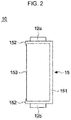
- FIG. 2 is a plan view of the pouch type secondary battery 10 according to an embodiment of the present invention.
- the pouch type secondary battery 10 may include a casing material 15 configured to accommodate an electrode assembly (11 in FIG. 4 ) from which electrode tabs 12a and 12b are led, and the casing material 15 may include a close contact portion 153 which is brought into close contact with the electrode assembly 11 at at least one side surface of side surfaces of the electrode assembly 11 and a sealing portion 151 which is formed by bonding the casing material 15 at portions other than the close contact portion 153.
- the sealing portion 151 may include extending portions 152 protruding perpendicularly with respect to the close contact portion 153 by a predetermined length L at a portion adjacent to the close contact portion 153 in the sealing portion 151.
- the secondary battery 10 may include the electrode assembly 11, and a positive electrode tab 12a and a negative electrode tab 12b which protrude from the electrode assembly 11 to the outside of the casing material 15.
- the electrode assembly 11 may be of a jelly-roll form wounded in a spiral form with a roll-shaped separator interposed between a positive electrode plate and a negative electrode plate.
- the electrode assembly 11 is not limited thereto, and may have a stacked shape in which a positive electrode plate, a separator, and a negative electrode plate are sequentially stacked.
- the positive electrode tab 12a and the negative electrode tab 12b may be electrically connected to a positive electrode plate and a negative electrode plate, respectively, and may protrude from both ends of the electrode assembly 11.
- the present invention is not limited thereto, and the positive electrode tab 12a and the negative electrode tab 12b may protrude from one end of the electrode assembly 11 and be spaced apart from each other. In an embodiment of the present invention, a case in which electrode tabs 12 protrude from both ends of the electrode assembly 11 will be described.
- the casing material 15 may accommodate the electrode assembly 11 from which the electrode tabs 12a and 12b are led.
- the casing material 15 may include aluminum.
- the use of aluminum for the casing material 15 may be for miniaturization, weight reduction, thinning, and resistance to severe thermal environments and mechanical impacts.
- a plurality of accommodation spaces 155a may be formed in the casing material 15 in a recessed shape, and the electrode assembly 11 may be disposed in the accommodation space 155a.
- the casing material 15 may be bonded along an outer periphery of the electrode assembly 11 after the electrode assembly 11 is disposed.
- the sealing portion 151 may be formed by bonding the casing material 15 along the outer periphery of the electrode assembly 11.
- the sealing portion 151 is formed by bonding the casing material 15 and may be formed along four sides around the side surface of the casing material 15.
- the electrode tabs 12a and 12b may be led to the outside of the sealing portion 151 at both ends of the electrode assembly 11.
- the electrode tabs 12a and 12b may be led from both ends of the electrode assembly 11 in a longitudinal direction (i.e., the vertical direction in FIG. 2 ) of the electrode assembly 11.
- the present invention is not limited thereto, and when the electrode tabs 12a and 12b are led from one end of the electrode assembly 11 and are spaced apart from each other, the electrode tabs 12a and 12b may be led from one end of the electrode assembly 11 to the outside of the sealing portion 151.
- a volume of the secondary battery module may be increased by as much as a length by which the sealing portion 151 is formed. Accordingly, in the pouch type secondary battery 10 according to an embodiment of the present invention, the casing material 15 is not formed along four sides forming the side surface of the electrode assembly 11 but is formed to be in close contact with the electrode assembly 11 on at least one of four sides forming the side surface of the electrode assembly 11, thereby reducing the volume of the secondary battery module.
- the casing material 15 may be brought into close contact with at least one side surface of the side surfaces of the electrode assembly 11.
- the close contact portion 153 may be formed in close contact with the electrode assembly 11. Accordingly, an excess portion of the sealing portion 151 is reduced when a secondary battery module is assembled, such that a space that may be formed between adjacent secondary batteries may be reduced. That is, adjacent secondary batteries may be in close contact with each other without creating a space therebetween because the casing material 15 is formed to be in close contact with one surface of the side surfaces of the electrode assembly 11, and the one surface is the surface in which the electrode tabs 12a and 12b are not formed. Accordingly, when assembling the secondary battery 10, the volumetric efficiency thereof may be increased.
- the sealing portion 151 may include at least one extending portion 152 protruding by a predetermined length at a position adjacent to the electrode tabs 12a and 12b.
- the extending portion 152 may protrude perpendicularly with respect to the close contact portion 153 by a predetermined length L at a portion adjacent to the close contact portion 153.
- the extending portion 152 may have a length of less than a few millimeters (mm).
- Two extending portions 152 may protrude in the same direction, or may protrude in a perpendicular direction with respect to a direction in which the electrode tab 12 protrudes.
- a position at which the extending portion 152 protrudes may be at least one side of the electrode assembly 11 in which the electrode tabs 12a and 12b are not formed.
- cooling efficiency of the secondary battery 10 may be improved by forming the close contact portion 153 on one surface of the secondary battery 10. That is, the close contact portion 153 may be in contact with a cooling plate (not shown) or the like capable of cooling the secondary battery 10.
- the plurality of secondary batteries 10 may be stacked in parallel so that the close contact portion 153 of each of the plurality of secondary batteries 10 is positioned downward, and a cooling plate capable of cooling the secondary battery 10 may be disposed on lower sides of the plurality of the secondary batteries 10 to be in contact with the close contact portion 153 of each of the plurality of secondary batteries 10.
- the cooling plate which has a flat shape, is brought into close contact with the close contact portion 153 and the extending portions 152 located at both ends of the close contact portion 153 extend in a vertical direction from the close contact portion 153, the extending portions 152 can serve to maintain arrangement of the secondary battery 10 with respect to the cooling plate.
- grooves capable of accommodating the extending portions 152 are formed in the cooling plate at predetermined intervals (intervals in which the secondary battery 10 are arranged), and the extending portions 152 are accommodated in the grooves, and thus the plurality of secondary batteries 10 may be maintained on the cooling plate.
- a concave portion (154 in FIG. 4 ) may be formed in a longitudinal direction at an intermediate position of the close contact portion 153.
- the electrode assembly 11 and the casing material 15 are in close contact with each other at the concave portion 154 more than at other portions of the close contact portion 153, and thus, heat transfer between the electrode assembly 11 and the casing material 15 may be more efficient. Accordingly, formation of the concave portion 154 may be more effective for cooling the pouch type secondary battery 10.
- FIG. 3 is a view showing a casing material 15 and a press frame 200 according to an embodiment of the present invention.
- the casing material 15 may be pressed by the press frame 200 to form a shape thereof.
- the press frame 200 may include a plurality of accommodation spaces 260 including a first accommodation space 260a and a second accommodation space 260b and a rounded part 240 formed at a gap between the first accommodation space 260a and the second accommodation space 260b. Further, the press frame 200 may include sealing parts 220 to form a sealing portion 151 of the casing material 15.
- the accommodation space 260 is a space configured to accommodate an electrode assembly 11, and may have a recessed shape.
- the press frame 200 according to an embodiment of the present invention is formed with two accommodation spaces 260a and 260b in accordance with a shape of the casing material 15, the present invention is not limited thereto. That is, in various embodiments of the present invention, the accommodation space may be formed in an appropriate number corresponding to the shape of the casing material 15.
- the rounded part 240 may be formed at an interval between the respective accommodation spaces 260a and 260b.
- the rounded part 240 may be formed to protrude convexly in a direction opposite to a recessed direction of the accommodation space 260.
- the rounded part 240 may have a convex curved shape.
- a cross section of the rounded part 240 may be semicircular.
- a circumference of the cross section of the rounded part 240 may be a semicircular circumference d from side A to B shown in FIG. 5 when the cross section of the rounded part 240 is semicircular.
- side A means an adjacent side of a first accommodation space 260a
- side B means an adjacent side of a second accommodation space 260b.
- An uppermost portion of the rounded part 240 may be located at the same height as the sealing parts 220 or at a height at which it is adjacent to the sealing parts 220.
- the rounded part 240 may prevent the casing material 15 from being broken during a process of pressing the casing material 15. This is because the rounded part 240 has an upwardly convex shape such that a concentration of stress received by the rounded part 240 may be minimized by the shape of the rounded part 240. Accordingly, it is possible to prevent the casing material 15 from being broken.
- the casing material 15 may be provided in a form of a sheet including aluminum or an aluminum alloy and may be pressed to a side in which the press frame 200 is located. Accordingly, the casing material 15 may be pressed into a shape of the press frame 200.
- FIG. 4A is a view showing a state in which the electrode assembly 11 is arranged in accommodation spaces 155 of the casing material 15 according to an embodiment of the present invention.
- FIG. 4B is a view showing a state in which the casing material 15 according to an embodiment of the present invention is bonded along an outer periphery of the electrode assembly 11.
- the electrode assembly 11 may be accommodated in the accommodation space 155 of the casing material 15 when the casing material 15 is pressed by the press frame 200,
- a space in which the electrode assembly 11 is disposed is defined as a first accommodation space 155a and a space in which the electrode assembly 11 is not disposed is referred to as a second accommodation space 155b.
- a shape of the casing material 15 is formed and the electrode assembly 11 may be disposed in the first accommodation space 155a of the casing material 15.
- a rounded portion 15a may be spread along at least one side surface of the side surfaces of the electrode assembly 11.
- the rounded portion 15a may have an upwardly convex curved shape.
- a cross section of the rounded portion 15a may be semicircular. Accordingly, the rounded portion 15a, which has a convex shape, may be spread along one side surface of the electrode assembly 11.
- a surface with which the rounded portion 15a is closely contacted may be a surface on which electrode tabs 12a and 12b are not formed. That is, an close contact portion 153 that is brought into close contact with the electrode assembly 11 may be formed as the rounded portion 15a is spread.
- a concave portion 154 corresponding to a center of the rounded portion 15a may be formed in the close contact portion 153 while the rounded portion 15a having the convex shape is brought into close contact with one side surface of the electrode assembly 11.
- a length of the circumference of the rounded portion 15a in a vertical cross section with respect to the rounded portion 15a may be a circumference d of a semicircle when the cross section of the rounded portion 15a is semicircular. That is, a circumference of the rounded portion 15a may be a semicircular circumference d from side A to B shown in FIG. 6A.
- the rounded portion 15a may be a portion formed by a curved surface from A to B. Portions other than a portion to be the close contact portion 153 may be a part of the extending portion 152 in the rounded portion 15a of the casing material 15. Since the shape of the rounded portion 15a corresponds to the curved surface, a portion (a portion adjacent to the close contact portion 153 in the extending portion 152) that is not in close contact with the electrode assembly 11 may slightly protrude when the casing material 15 is folded as shown in FIG. 6B.
- the second accommodation space 155b may cover the upper side of the electrode assembly 11 when the rounded portion 15a is brought into close contact with the electrode assembly 11.
- the electrode assembly 11 is accommodated and sealed in the casing material 20 so that the pouch type secondary battery 10 may be formed.
Abstract
Description
- The present invention relates to a pouch type secondary battery and a method of fabricating the same.
- As low-carbon green growth is emerging as a global issue around the world, the green energy industry is receiving great attention. Recently, development of electric vehicles or energy storage devices for storing renewable energy have been attracting great attention in dealing with the depletion of fossil fuels and reducing carbon dioxide.
- Since an electric vehicle is driven by using electric energy as a main power source from a battery, without an engine, an electric vehicle does not generate exhaust gas. Further, since the vehicle is driven by using only electric energy from a battery, energy density of the battery should be high compared to a volume occupied by the battery and a weight of the battery. Accordingly, it has been necessary to develop a technique for generating high energy density in secondary batteries of an electric vehicle. Lately, there is a strong demand for extending the lifespan of such secondary batteries, and there is an increasing need for a technique for maintaining performance of secondary batteries even when the secondary batteries are exposed to high temperatures for a long time.
- A typical pouch type secondary battery may be formed by wrapping an electrode assembly with a casing material. Here, a sealing portion is formed by sealing an outermost portion of the casing material in which an electrode assembly is accommodated. However, when a secondary battery module is assembled in a state in which the sealing portion protrudes, a total volume of the secondary battery module is increased due to the sealing portion, such that energy density of the secondary battery module may be lowered.
- Korean Patent Publication No.
10-1520153 (May 07, 2015 - Embodiments of the present invention provide a pouch type secondary battery module capable of improving density of a secondary battery module by forming a sealing portion of the pouch type secondary battery module to be smaller and a method of fabricating the same.
- Embodiments of the present invention provide a pouch type secondary battery module which reduces an increase in volume of a sealing portion formed by attaching a casing material to a secondary battery module and a method of fabricating the same.
- Embodiments of the present invention provide a pouch type secondary battery module which improves cooling efficiency and a method of fabricating the same.
- One aspect of the present invention provides a pouch type secondary battery including a casing material configured to accommodate an electrode assembly from which electrode tabs are led; and the casing material includes a sealing portion formed on three of four sides of the pouch type secondary battery and includes an close contact portion formed on the one remaining side; and an extending portion protruding perpendicularly with respect to the close contact portion is formed in the sealing portion in a portion adjacent to the close contact portion.
- A concave portion may be formed in a longitudinal direction of the close contact portion.
- A plurality of accommodation spaces configured to accommodate the electrode assembly and a rounded portion having an upwardly convex shape located at a gap between the plurality of accommodation spaces may be formed in the casing material before the electrode assembly is accommodated in the casing material, and the concave portion may be at least a part of the rounded portion.
- The casing material may include aluminum or an aluminum alloy.
- Another aspect of the present invention provides a method of fabricating a pouch type secondary battery, the method including: providing an electrode assembly at which electrode tabs are connected; forming a casing material on which a rounded portion of an upwardly convex shape is formed at a gap between a plurality of accommodation spaces configured to accommodate an electrode assembly; accommodating the electrode assembly in one of the plurality of accommodation spaces of the casing material so that the electrode tab is led to an outside; forming an close contact portion, which is brought into close contact with at least one side surface of side surfaces of the electrode assembly, on the casing material in a state in which the electrode assembly is accommodated in the accommodation space; forming a sealing portion by bonding the casing material at portions other than the close contact portion; and forming an extending portion protruding perpendicularly with respect to the close contact portion by a predetermined length in the sealing portion at a portion adjacent to the close contact portion.
- A press in which a plurality of accommodation spaces and a rounded part of an upwardly convex shape formed at a gap between the accommodation spaces are formed may be used to form a shape of the casing material, and the casing material may be provided in a sheet form and may be pressed to the side in which the press is located.
- The rounded portion may be spread along at least one side surface of the side surfaces of the electrode assembly when the one remaining accommodation space of the plurality of accommodation spaces covers the electrode assembly.
- The rounded portion is spread and an close contact portion which is brought into close contact with the electrode assembly may be formed.
- The casing material may include aluminum or an aluminum alloy.
- Embodiments of the present invention provide a pouch type secondary battery module capable of improving density of a secondary battery module by forming a sealing portion of the pouch type secondary battery module to be reduced and a fabricating method.
- Embodiments of the present invention provide a pouch type secondary battery module which reduces an increase in volume of a sealing portion which is formed by closely attaching a casing material to a secondary battery module and a fabricating method.
- Embodiments of the present invention provide a pouch type secondary battery module in which a cooling plate configured to cool a secondary battery module can be arranged not only in an arrangement direction side in which the secondary battery module is arranged but also in a direction perpendicular to the arrangement direction, thereby improving cooling efficiency, and a fabricating method.
-
-
FIG. 1 is a perspective view of a pouch type secondary battery module according to an embodiment of the present invention. -
FIG. 2 is a plan view of the pouch type secondary battery module according to an embodiment of the present invention. -
FIG. 3 is a view showing a casing material and a press according to an embodiment of the present invention. -
FIG. 4A is a view showing a state in which an electrode assembly is arranged in an accommodation space of a casing material according to an embodiment of the present invention. -
FIG. 4B is a view showing a state in which the casing material according to an embodiment of the present invention is bonded along an outer periphery of the electrode assembly. - Hereinafter, specific embodiments of the present invention will be described with reference to the drawings. However, this is an exemplary embodiment only and the present invention is not limited thereto.
- In descriptions of the invention, when it is determined that detailed descriptions of related well-known functions unnecessarily obscure the gist of the invention, detailed descriptions thereof will be omitted. Some terms described below are defined by considering functions in the invention and meanings may vary depending on, for example, a user or operator's intentions or customs. Therefore, the meanings of terms should be interpreted based on the scope throughout this specification.
- The spirit of the invention is defined by the appended claims. The following embodiments are only made to efficiently describe the progressive technological scope of the invention to those skilled in the art.
- A secondary battery used in various electric devices such as an electric vehicle may be, for example, a pouch type battery of a lithium ion battery or of a lithium polymer battery, and hereinafter, they will all be referred to as secondary batteries.
-
FIG. 1 is a perspective view of a pouch typesecondary battery 10 according to an embodiment of the present invention.FIG. 2 is a plan view of the pouch typesecondary battery 10 according to an embodiment of the present invention. - Referring to
FIGS. 1 and2 , the pouch typesecondary battery 10 may include acasing material 15 configured to accommodate an electrode assembly (11 inFIG. 4 ) from whichelectrode tabs casing material 15 may include aclose contact portion 153 which is brought into close contact with theelectrode assembly 11 at at least one side surface of side surfaces of theelectrode assembly 11 and asealing portion 151 which is formed by bonding thecasing material 15 at portions other than theclose contact portion 153. The sealingportion 151 may include extendingportions 152 protruding perpendicularly with respect to theclose contact portion 153 by a predetermined length L at a portion adjacent to theclose contact portion 153 in thesealing portion 151. - The
secondary battery 10 may include theelectrode assembly 11, and apositive electrode tab 12a and anegative electrode tab 12b which protrude from theelectrode assembly 11 to the outside of thecasing material 15. Theelectrode assembly 11 may be of a jelly-roll form wounded in a spiral form with a roll-shaped separator interposed between a positive electrode plate and a negative electrode plate. However, theelectrode assembly 11 is not limited thereto, and may have a stacked shape in which a positive electrode plate, a separator, and a negative electrode plate are sequentially stacked. Thepositive electrode tab 12a and thenegative electrode tab 12b may be electrically connected to a positive electrode plate and a negative electrode plate, respectively, and may protrude from both ends of theelectrode assembly 11. However, the present invention is not limited thereto, and thepositive electrode tab 12a and thenegative electrode tab 12b may protrude from one end of theelectrode assembly 11 and be spaced apart from each other. In an embodiment of the present invention, a case in which electrode tabs 12 protrude from both ends of theelectrode assembly 11 will be described. - The
casing material 15 may accommodate theelectrode assembly 11 from which theelectrode tabs casing material 15 may include aluminum. The use of aluminum for thecasing material 15 may be for miniaturization, weight reduction, thinning, and resistance to severe thermal environments and mechanical impacts. A plurality ofaccommodation spaces 155a (seeFIG. 4A ) may be formed in thecasing material 15 in a recessed shape, and theelectrode assembly 11 may be disposed in theaccommodation space 155a. Thecasing material 15 may be bonded along an outer periphery of theelectrode assembly 11 after theelectrode assembly 11 is disposed. - The sealing
portion 151 may be formed by bonding thecasing material 15 along the outer periphery of theelectrode assembly 11. The sealingportion 151 is formed by bonding thecasing material 15 and may be formed along four sides around the side surface of thecasing material 15. Here, theelectrode tabs portion 151 at both ends of theelectrode assembly 11. For example, theelectrode tabs electrode assembly 11 in a longitudinal direction (i.e., the vertical direction inFIG. 2 ) of theelectrode assembly 11. However, the present invention is not limited thereto, and when theelectrode tabs electrode assembly 11 and are spaced apart from each other, theelectrode tabs electrode assembly 11 to the outside of the sealingportion 151. - Here, a volume of the secondary battery module may be increased by as much as a length by which the sealing
portion 151 is formed. Accordingly, in the pouch typesecondary battery 10 according to an embodiment of the present invention, thecasing material 15 is not formed along four sides forming the side surface of theelectrode assembly 11 but is formed to be in close contact with theelectrode assembly 11 on at least one of four sides forming the side surface of theelectrode assembly 11, thereby reducing the volume of the secondary battery module. - The
casing material 15 may be brought into close contact with at least one side surface of the side surfaces of theelectrode assembly 11. Here, a portion of thecasing material 15 which is brought into close contact with theelectrode assembly 11 will be described as theclose contact portion 153. Theclose contact portion 153 may be formed in close contact with theelectrode assembly 11. Accordingly, an excess portion of the sealingportion 151 is reduced when a secondary battery module is assembled, such that a space that may be formed between adjacent secondary batteries may be reduced. That is, adjacent secondary batteries may be in close contact with each other without creating a space therebetween because thecasing material 15 is formed to be in close contact with one surface of the side surfaces of theelectrode assembly 11, and the one surface is the surface in which theelectrode tabs secondary battery 10, the volumetric efficiency thereof may be increased. - The sealing
portion 151 according to an embodiment of the present invention may include at least one extendingportion 152 protruding by a predetermined length at a position adjacent to theelectrode tabs - Here, the extending
portion 152 may protrude perpendicularly with respect to theclose contact portion 153 by a predetermined length L at a portion adjacent to theclose contact portion 153. Here, the extendingportion 152 may have a length of less than a few millimeters (mm). Two extendingportions 152 may protrude in the same direction, or may protrude in a perpendicular direction with respect to a direction in which the electrode tab 12 protrudes. Further, a position at which the extendingportion 152 protrudes may be at least one side of theelectrode assembly 11 in which theelectrode tabs - Furthermore, cooling efficiency of the
secondary battery 10 may be improved by forming theclose contact portion 153 on one surface of thesecondary battery 10. That is, theclose contact portion 153 may be in contact with a cooling plate (not shown) or the like capable of cooling thesecondary battery 10. For example, the plurality ofsecondary batteries 10 may be stacked in parallel so that theclose contact portion 153 of each of the plurality ofsecondary batteries 10 is positioned downward, and a cooling plate capable of cooling thesecondary battery 10 may be disposed on lower sides of the plurality of thesecondary batteries 10 to be in contact with theclose contact portion 153 of each of the plurality ofsecondary batteries 10. - Further, since the cooling plate, which has a flat shape, is brought into close contact with the
close contact portion 153 and the extendingportions 152 located at both ends of theclose contact portion 153 extend in a vertical direction from theclose contact portion 153, the extendingportions 152 can serve to maintain arrangement of thesecondary battery 10 with respect to the cooling plate. For example, grooves capable of accommodating the extendingportions 152 are formed in the cooling plate at predetermined intervals (intervals in which thesecondary battery 10 are arranged), and the extendingportions 152 are accommodated in the grooves, and thus the plurality ofsecondary batteries 10 may be maintained on the cooling plate. - Further, a concave portion (154 in
FIG. 4 ) may be formed in a longitudinal direction at an intermediate position of theclose contact portion 153. Theelectrode assembly 11 and thecasing material 15 are in close contact with each other at theconcave portion 154 more than at other portions of theclose contact portion 153, and thus, heat transfer between theelectrode assembly 11 and thecasing material 15 may be more efficient. Accordingly, formation of theconcave portion 154 may be more effective for cooling the pouch typesecondary battery 10. - Further, a method of fabricating the pouch type
secondary battery 10 according to an embodiment of the present invention will be described. -
FIG. 3 is a view showing acasing material 15 and apress frame 200 according to an embodiment of the present invention. - As shown in
FIG. 3 , thecasing material 15 may be pressed by thepress frame 200 to form a shape thereof. - The
press frame 200 may include a plurality ofaccommodation spaces 260 including afirst accommodation space 260a and asecond accommodation space 260b and arounded part 240 formed at a gap between thefirst accommodation space 260a and thesecond accommodation space 260b. Further, thepress frame 200 may include sealingparts 220 to form a sealingportion 151 of thecasing material 15. - The
accommodation space 260 is a space configured to accommodate anelectrode assembly 11, and may have a recessed shape. Although thepress frame 200 according to an embodiment of the present invention is formed with twoaccommodation spaces casing material 15, the present invention is not limited thereto. That is, in various embodiments of the present invention, the accommodation space may be formed in an appropriate number corresponding to the shape of thecasing material 15. - The
rounded part 240 may be formed at an interval between therespective accommodation spaces rounded part 240 may be formed to protrude convexly in a direction opposite to a recessed direction of theaccommodation space 260. Therounded part 240 may have a convex curved shape. For example, a cross section of therounded part 240 may be semicircular. - As described above, although the shape of the
rounded part 240 is not limited, a circumference of the cross section of therounded part 240 may be a semicircular circumference d from side A to B shown in FIG. 5 when the cross section of therounded part 240 is semicircular. Here, side A means an adjacent side of afirst accommodation space 260a, and side B means an adjacent side of asecond accommodation space 260b. An uppermost portion of therounded part 240 may be located at the same height as the sealingparts 220 or at a height at which it is adjacent to the sealingparts 220. - In addition, the
rounded part 240 may prevent thecasing material 15 from being broken during a process of pressing thecasing material 15. This is because therounded part 240 has an upwardly convex shape such that a concentration of stress received by therounded part 240 may be minimized by the shape of therounded part 240. Accordingly, it is possible to prevent thecasing material 15 from being broken. - The
casing material 15 may be provided in a form of a sheet including aluminum or an aluminum alloy and may be pressed to a side in which thepress frame 200 is located. Accordingly, thecasing material 15 may be pressed into a shape of thepress frame 200. -
FIG. 4A is a view showing a state in which theelectrode assembly 11 is arranged inaccommodation spaces 155 of thecasing material 15 according to an embodiment of the present invention.FIG. 4B is a view showing a state in which thecasing material 15 according to an embodiment of the present invention is bonded along an outer periphery of theelectrode assembly 11. - Referring to
FIGS. 4A and 4B , theelectrode assembly 11 may be accommodated in theaccommodation space 155 of thecasing material 15 when thecasing material 15 is pressed by thepress frame 200, - In the following description, in the
accommodation spaces 155 of thecasing material 15, a space in which theelectrode assembly 11 is disposed is defined as afirst accommodation space 155a and a space in which theelectrode assembly 11 is not disposed is referred to as asecond accommodation space 155b. - A shape of the
casing material 15 is formed and theelectrode assembly 11 may be disposed in thefirst accommodation space 155a of thecasing material 15. - When the
electrode assembly 11 is disposed, arounded portion 15a may be spread along at least one side surface of the side surfaces of theelectrode assembly 11. - The
rounded portion 15a may have an upwardly convex curved shape. For example, a cross section of therounded portion 15a may be semicircular. Accordingly, therounded portion 15a, which has a convex shape, may be spread along one side surface of theelectrode assembly 11. - Here, a surface with which the rounded
portion 15a is closely contacted may be a surface on whichelectrode tabs close contact portion 153 that is brought into close contact with theelectrode assembly 11 may be formed as therounded portion 15a is spread. - As described above, a
concave portion 154 corresponding to a center of therounded portion 15a may be formed in theclose contact portion 153 while therounded portion 15a having the convex shape is brought into close contact with one side surface of theelectrode assembly 11. Further, although the shape of therounded portion 15a is not limited, a length of the circumference of therounded portion 15a in a vertical cross section with respect to therounded portion 15a may be a circumference d of a semicircle when the cross section of therounded portion 15a is semicircular. That is, a circumference of therounded portion 15a may be a semicircular circumference d from side A to B shown in FIG. 6A. Here, side A means an adjacent side of thefirst accommodation space 155a, and side B means an adjacent side of the second accommodation space 255b. Accordingly, therounded portion 15a may be a portion formed by a curved surface from A to B. Portions other than a portion to be theclose contact portion 153 may be a part of the extendingportion 152 in therounded portion 15a of thecasing material 15. Since the shape of therounded portion 15a corresponds to the curved surface, a portion (a portion adjacent to theclose contact portion 153 in the extending portion 152) that is not in close contact with theelectrode assembly 11 may slightly protrude when thecasing material 15 is folded as shown in FIG. 6B. - The
second accommodation space 155b may cover the upper side of theelectrode assembly 11 when therounded portion 15a is brought into close contact with theelectrode assembly 11. - Accordingly, the
electrode assembly 11 is accommodated and sealed in the casing material 20 so that the pouch typesecondary battery 10 may be formed. - While the present invention has been described above in detail with reference to representative embodiments, it may be understood by those skilled in the art that the embodiment may be variously modified without departing from the scope of the present invention. Therefore, the scope of the present invention is defined not by the described embodiment but by the appended claims, and encompasses equivalents that fall within the scope of the appended claims.
-
- 10:
- POUCH TYPE SECONDARY BATTERY
- 11:
- ELECTRODE ASSEMBLY
- 12:
- ELECTRODE TAB
- 15:
- CASING MATERIAL
- 15A:
- ROUNDED PORTION
- 151:
- SEALING PORTION
- 152:
- EXTENDING PORTION
- 153:
- CLOSE CONTACT PORTION
- 154:
- CONCAVE PORTION
- 155:
- ACCOMMODATION SPACE
Claims (9)
- A pouch type secondary battery comprising:a casing material configured to accommodate an electrode assembly from which an electrode tab is led,wherein a sealing portion formed on three of four sides of the pouch type secondary battery and an close contact portion formed on one remaining side are formed by the casing material, andan extending portion protruding perpendicularly with respect to the close contact portion is formed in the sealing portion in a portion adjacent to the close contact portion.
- The pouch type secondary battery of claim 1, wherein a concave portion is formed in a longitudinal direction of the close contact portion.
- The pouch type secondary battery of claim 2, wherein a plurality of accommodation spaces configured to accommodate the electrode assembly and a rounded portion having an upwardly convex shape located at a gap between the plurality of accommodation spaces are formed in the casing material before the electrode assembly is accommodated in the casing material, and the concave portion is at least a part of the rounded portion.
- The pouch type secondary battery of claim 1, wherein the casing material includes aluminum or an aluminum alloy.
- A method of fabricating a pouch type secondary battery, the method comprising:providing an electrode assembly connected to an electrode tab;forming a casing material on which a rounded portion of an upwardly convex shape is formed at a gap between a plurality of accommodation spaces configured to accommodate the electrode assembly;accommodating the electrode assembly in one of the plurality of accommodation spaces of the casing material so that the electrode tab is led to an outside;forming an close contact portion, which is brought into close contact with at least one side surface of side surfaces of the electrode assembly, on the casing material in a state in which the electrode assembly is accommodated in the accommodation space;forming a sealing portion by bonding the casing material at portions other than the close contact portion; andforming an extending portion protruding perpendicular to the close contact portion by a predetermined length in the sealing portion at a portion adjacent to the close contact portion.
- The method of claim 5, wherein a press in which a plurality of accommodation spaces and a rounded part of an upwardly convex shape formed at a gap between the accommodation spaces are formed is used to form a shape of the casing material, and the casing material is provided in a sheet form and pressed to the side in which the press is located.
- The method of claim 5, wherein the rounded portion is spread along at least one side surface of the side surfaces of the electrode assembly when one remaining accommodation space of the plurality of accommodation spaces covers the electrode assembly.
- The method of claim 7, wherein the rounded portion is spread and an close contact portion which is brought into close contact with the electrode assembly is formed.
- The method of claim 9, wherein the casing material includes aluminum or an aluminum alloy.
Applications Claiming Priority (2)
| Application Number | Priority Date | Filing Date | Title |
|---|---|---|---|
| KR20160174846 | 2016-12-20 | ||
| PCT/KR2017/015154 WO2018117654A1 (en) | 2016-12-20 | 2017-12-20 | Pouch-type secondary battery and manufacturing method therefor |
Publications (2)
| Publication Number | Publication Date |
|---|---|
| EP3561898A1 true EP3561898A1 (en) | 2019-10-30 |
| EP3561898A4 EP3561898A4 (en) | 2020-08-26 |
Family
ID=62780078
Family Applications (1)
| Application Number | Title | Priority Date | Filing Date |
|---|---|---|---|
| EP17885243.0A Pending EP3561898A4 (en) | 2016-12-20 | 2017-12-20 | Pouch-type secondary battery and manufacturing method therefor |
Country Status (3)
| Country | Link |
|---|---|
| EP (1) | EP3561898A4 (en) |
| KR (1) | KR102654935B1 (en) |
| CN (3) | CN110114898B (en) |
Cited By (1)
| Publication number | Priority date | Publication date | Assignee | Title |
|---|---|---|---|---|
| EP4050704A4 (en) * | 2019-12-17 | 2023-05-03 | LG Energy Solution, Ltd. | Case for secondary battery, and secondary battery |
Families Citing this family (4)
| Publication number | Priority date | Publication date | Assignee | Title |
|---|---|---|---|---|
| KR101927262B1 (en) * | 2015-11-03 | 2018-12-10 | 주식회사 엘지화학 | A pouch case for a secondary battery |
| JP7360820B2 (en) * | 2019-05-30 | 2023-10-13 | 日立造船株式会社 | Secondary battery and its manufacturing method |
| KR20210069594A (en) * | 2019-12-03 | 2021-06-11 | 주식회사 엘지화학 | Pouch type secondary battery, battery pack and method of manufacturing the pouch type secondary battery |
| KR102566013B1 (en) * | 2021-03-30 | 2023-08-10 | 주식회사 엘지에너지솔루션 | Pouch type secondary battery and battery module having the same |
Family Cites Families (36)
| Publication number | Priority date | Publication date | Assignee | Title |
|---|---|---|---|---|
| JPH11213964A (en) * | 1998-01-21 | 1999-08-06 | Sanyo Electric Co Ltd | Thin battery and its manufacture |
| JP2001060452A (en) * | 1999-08-20 | 2001-03-06 | Toshiba Battery Co Ltd | Manufacture of film-jacketed battery |
| JP4140311B2 (en) * | 2002-08-05 | 2008-08-27 | トヨタ自動車株式会社 | Method for manufacturing case for power storage element |
| KR100496305B1 (en) * | 2003-05-22 | 2005-06-17 | 삼성에스디아이 주식회사 | Pouched-type lithium secondary battery and the fabrication method thereof |
| CN2701078Y (en) * | 2004-04-30 | 2005-05-18 | 比亚迪股份有限公司 | A soft packaging lithium ion battery |
| KR100624959B1 (en) * | 2004-10-28 | 2006-09-15 | 삼성에스디아이 주식회사 | Li Secondary Battery and Method of fabricating the same |
| JP4968423B2 (en) * | 2005-05-30 | 2012-07-04 | 大日本印刷株式会社 | Lithium battery exterior |
| KR100895202B1 (en) * | 2006-04-17 | 2009-05-06 | 주식회사 엘지화학 | Pouch-type Battery |
| JP2008159440A (en) * | 2006-12-25 | 2008-07-10 | Calsonic Kansei Corp | Vehicular battery cooling system |
| KR100891383B1 (en) * | 2007-05-21 | 2009-04-02 | 삼성에스디아이 주식회사 | Pouch type secondary battery |
| KR100876254B1 (en) * | 2007-07-20 | 2008-12-26 | 삼성에스디아이 주식회사 | Pouth type lithium secondary battery |
| KR100917736B1 (en) * | 2007-09-14 | 2009-09-15 | 삼성에스디아이 주식회사 | Pouch for battery and pouch type secondary battery |
| KR100998845B1 (en) * | 2007-11-09 | 2010-12-08 | 주식회사 엘지화학 | Battery Module of Heat Dissipation Property, Heat Exchange Member, and Large or Middle-sized Battery Pack Employed with the Same |
| WO2011099793A2 (en) * | 2010-02-10 | 2011-08-18 | 주식회사 엘지화학 | Rechargeable lithium battery in pouch form |
| US9638475B2 (en) * | 2010-10-29 | 2017-05-02 | Dana Canada Corporation | Heat exchanger and battery unit structure for cooling thermally conductive batteries |
| KR101765769B1 (en) * | 2010-12-29 | 2017-08-07 | 에스케이이노베이션 주식회사 | Battery module and tab ultrasonic wave welding method |
| KR101816813B1 (en) * | 2010-12-30 | 2018-01-11 | 에스케이이노베이션 주식회사 | Case of pouched type cell |
| JP2013546136A (en) * | 2011-06-22 | 2013-12-26 | エルジー・ケム・リミテッド | Pouch and pouch-type secondary battery |
| KR101369325B1 (en) * | 2011-06-30 | 2014-03-04 | 주식회사 엘지화학 | Secondary electric cell with enhanced contact resistance |
| US9324981B2 (en) * | 2012-01-20 | 2016-04-26 | GM Global Technology Operations LLC | Cell frame for extended range electric vehicle battery module |
| KR20140004305A (en) * | 2012-07-02 | 2014-01-13 | 에스케이이노베이션 주식회사 | Pouch type secondary battery and sealing method of pouch type secondary battery |
| KR101520153B1 (en) | 2012-09-11 | 2015-05-13 | 주식회사 엘지화학 | Pouch cell for secondary battery and method for manufacturing the same |
| KR20140123007A (en) * | 2013-04-11 | 2014-10-21 | 주식회사 엘지화학 | Battery Cell Having Round Corner |
| KR102052588B1 (en) * | 2013-08-13 | 2019-12-05 | 삼성에스디아이 주식회사 | Rechargeable battery pack |
| KR101707192B1 (en) * | 2013-11-28 | 2017-02-15 | 주식회사 엘지화학 | Secondary battery sealed with sealant and method thereof |
| KR20160017759A (en) * | 2014-08-04 | 2016-02-17 | 삼성에스디아이 주식회사 | Rechargeable battery having edge bonding part |
| CN204289626U (en) * | 2014-09-12 | 2015-04-22 | 深圳瑞隆新能源科技有限公司 | A kind of mould improving poly-lithium battery capacity per unit area |
| KR20160041402A (en) * | 2014-10-07 | 2016-04-18 | 주식회사 엘지화학 | Pouch type secondary battery and a method of making the same |
| KR20160045468A (en) * | 2014-10-17 | 2016-04-27 | 주식회사 엘지화학 | Pouch type secondary battery and a method of making the same |
| KR101863703B1 (en) * | 2014-10-20 | 2018-06-01 | 주식회사 엘지화학 | Pouch-type secondary battery and method for manufacturing the same |
| KR101795705B1 (en) * | 2015-02-26 | 2017-11-08 | 주식회사 엘지화학 | Cartridge for pouch typed secondary battery |
| KR101865995B1 (en) * | 2015-03-27 | 2018-06-08 | 주식회사 엘지화학 | Battery module |
| KR102318043B1 (en) * | 2015-04-22 | 2021-10-28 | 에스케이이노베이션 주식회사 | Secondary battery and battery module having the same |
| KR101792751B1 (en) * | 2015-05-13 | 2017-10-31 | 주식회사 엘지화학 | Battery module |
| KR102064460B1 (en) * | 2016-09-12 | 2020-01-10 | 주식회사 엘지화학 | Pouch case for secondary battery, pouch type secondary battery and manufacturing method thereof using the same |
| KR102348298B1 (en) * | 2016-12-06 | 2022-01-07 | 에스케이온 주식회사 | Secondary battery module |
-
2017
- 2017-12-20 EP EP17885243.0A patent/EP3561898A4/en active Pending
- 2017-12-20 CN CN201780078039.7A patent/CN110114898B/en active Active
- 2017-12-20 KR KR1020170175973A patent/KR102654935B1/en active IP Right Grant
- 2017-12-20 CN CN202211048815.8A patent/CN115425339B/en active Active
- 2017-12-20 CN CN202211048714.0A patent/CN115425338A/en active Pending
Cited By (1)
| Publication number | Priority date | Publication date | Assignee | Title |
|---|---|---|---|---|
| EP4050704A4 (en) * | 2019-12-17 | 2023-05-03 | LG Energy Solution, Ltd. | Case for secondary battery, and secondary battery |
Also Published As
| Publication number | Publication date |
|---|---|
| CN110114898B (en) | 2022-09-16 |
| CN110114898A (en) | 2019-08-09 |
| KR102654935B1 (en) | 2024-04-04 |
| KR20180071983A (en) | 2018-06-28 |
| EP3561898A4 (en) | 2020-08-26 |
| CN115425339A (en) | 2022-12-02 |
| CN115425338A (en) | 2022-12-02 |
| CN115425339B (en) | 2024-03-22 |
Similar Documents
| Publication | Publication Date | Title |
|---|---|---|
| CN109643768B (en) | Secondary battery module | |
| EP3561898A1 (en) | Pouch-type secondary battery and manufacturing method therefor | |
| CN108431986B (en) | Pouch exterior for secondary battery, pouch type secondary battery using the same, and method of manufacturing the pouch type secondary battery | |
| US11276893B2 (en) | Pouch secondary battery and method of fabricating the same | |
| EP4338934A2 (en) | Method for manufacturing secondary battery and pouch for secondary battery | |
| JP2005285773A (en) | Electrode assembly and secondary battery with the same | |
| US20120040226A1 (en) | Battery Module | |
| EP3567669B1 (en) | Battery module, battery pack comprising battery module, and automobile comprising battery pack | |
| EP2744015A1 (en) | Battery block and battery module comprising same | |
| EP3107142B1 (en) | Battery cell having asymmetric and indented structure | |
| JP2006093154A (en) | Secondary battery | |
| US20150171404A1 (en) | Battery module | |
| KR20190114645A (en) | Pouch case, and secondary battery and secondary battery pack using the same | |
| CN106207070B (en) | Secondary battery | |
| KR20140004835A (en) | Battery pack | |
| KR20140039349A (en) | Secondary battery of improved cooling efficiency | |
| JP6247486B2 (en) | Assembled battery | |
| CN110635069A (en) | Pouch type case and secondary battery using the same | |
| US9065082B2 (en) | Electric storage device | |
| KR101884410B1 (en) | Battery pack | |
| KR20240049241A (en) | Pouch type secondary battery and method of fabricating same | |
| KR102466867B1 (en) | Pouch type battery module | |
| KR102238177B1 (en) | Battery cell and method of preparing electrode lead |
Legal Events
| Date | Code | Title | Description |
|---|---|---|---|
| STAA | Information on the status of an ep patent application or granted ep patent |
Free format text: STATUS: THE INTERNATIONAL PUBLICATION HAS BEEN MADE |
|
| PUAI | Public reference made under article 153(3) epc to a published international application that has entered the european phase |
Free format text: ORIGINAL CODE: 0009012 |
|
| STAA | Information on the status of an ep patent application or granted ep patent |
Free format text: STATUS: REQUEST FOR EXAMINATION WAS MADE |
|
| 17P | Request for examination filed |
Effective date: 20190719 |
|
| AK | Designated contracting states |
Kind code of ref document: A1 Designated state(s): AL AT BE BG CH CY CZ DE DK EE ES FI FR GB GR HR HU IE IS IT LI LT LU LV MC MK MT NL NO PL PT RO RS SE SI SK SM TR |
|
| AX | Request for extension of the european patent |
Extension state: BA ME |
|
| DAV | Request for validation of the european patent (deleted) | ||
| DAX | Request for extension of the european patent (deleted) | ||
| A4 | Supplementary search report drawn up and despatched |
Effective date: 20200728 |
|
| RIC1 | Information provided on ipc code assigned before grant |
Ipc: H01M 10/04 20060101ALI20200722BHEP Ipc: H01M 2/10 20060101ALI20200722BHEP Ipc: H01M 2/02 20060101AFI20200722BHEP |
|
| STAA | Information on the status of an ep patent application or granted ep patent |
Free format text: STATUS: EXAMINATION IS IN PROGRESS |
|
| 17Q | First examination report despatched |
Effective date: 20210407 |
|
| STAA | Information on the status of an ep patent application or granted ep patent |
Free format text: STATUS: EXAMINATION IS IN PROGRESS |
|
| RAP1 | Party data changed (applicant data changed or rights of an application transferred) |
Owner name: SK ON CO., LTD. |
|
| P01 | Opt-out of the competence of the unified patent court (upc) registered |
Effective date: 20230602 |