EP3561840A1 - Gas-insulation switch device - Google Patents
Gas-insulation switch device Download PDFInfo
- Publication number
- EP3561840A1 EP3561840A1 EP16923924.1A EP16923924A EP3561840A1 EP 3561840 A1 EP3561840 A1 EP 3561840A1 EP 16923924 A EP16923924 A EP 16923924A EP 3561840 A1 EP3561840 A1 EP 3561840A1
- Authority
- EP
- European Patent Office
- Prior art keywords
- contact
- gas
- fixed
- movable
- movable contact
- Prior art date
- Legal status (The legal status is an assumption and is not a legal conclusion. Google has not performed a legal analysis and makes no representation as to the accuracy of the status listed.)
- Granted
Links
Images




Classifications
-
- H—ELECTRICITY
- H01—ELECTRIC ELEMENTS
- H01H—ELECTRIC SWITCHES; RELAYS; SELECTORS; EMERGENCY PROTECTIVE DEVICES
- H01H33/00—High-tension or heavy-current switches with arc-extinguishing or arc-preventing means
- H01H33/70—Switches with separate means for directing, obtaining, or increasing flow of arc-extinguishing fluid
- H01H33/88—Switches with separate means for directing, obtaining, or increasing flow of arc-extinguishing fluid the flow of arc-extinguishing fluid being produced or increased by movement of pistons or other pressure-producing parts
-
- H—ELECTRICITY
- H01—ELECTRIC ELEMENTS
- H01H—ELECTRIC SWITCHES; RELAYS; SELECTORS; EMERGENCY PROTECTIVE DEVICES
- H01H33/00—High-tension or heavy-current switches with arc-extinguishing or arc-preventing means
- H01H33/70—Switches with separate means for directing, obtaining, or increasing flow of arc-extinguishing fluid
- H01H33/88—Switches with separate means for directing, obtaining, or increasing flow of arc-extinguishing fluid the flow of arc-extinguishing fluid being produced or increased by movement of pistons or other pressure-producing parts
- H01H33/90—Switches with separate means for directing, obtaining, or increasing flow of arc-extinguishing fluid the flow of arc-extinguishing fluid being produced or increased by movement of pistons or other pressure-producing parts this movement being effected by or in conjunction with the contact-operating mechanism
-
- H—ELECTRICITY
- H01—ELECTRIC ELEMENTS
- H01H—ELECTRIC SWITCHES; RELAYS; SELECTORS; EMERGENCY PROTECTIVE DEVICES
- H01H33/00—High-tension or heavy-current switches with arc-extinguishing or arc-preventing means
- H01H33/70—Switches with separate means for directing, obtaining, or increasing flow of arc-extinguishing fluid
- H01H33/88—Switches with separate means for directing, obtaining, or increasing flow of arc-extinguishing fluid the flow of arc-extinguishing fluid being produced or increased by movement of pistons or other pressure-producing parts
- H01H33/90—Switches with separate means for directing, obtaining, or increasing flow of arc-extinguishing fluid the flow of arc-extinguishing fluid being produced or increased by movement of pistons or other pressure-producing parts this movement being effected by or in conjunction with the contact-operating mechanism
- H01H33/904—Switches with separate means for directing, obtaining, or increasing flow of arc-extinguishing fluid the flow of arc-extinguishing fluid being produced or increased by movement of pistons or other pressure-producing parts this movement being effected by or in conjunction with the contact-operating mechanism characterised by the transmission between operating mechanism and piston or movable contact
-
- H—ELECTRICITY
- H01—ELECTRIC ELEMENTS
- H01H—ELECTRIC SWITCHES; RELAYS; SELECTORS; EMERGENCY PROTECTIVE DEVICES
- H01H33/00—High-tension or heavy-current switches with arc-extinguishing or arc-preventing means
- H01H33/70—Switches with separate means for directing, obtaining, or increasing flow of arc-extinguishing fluid
- H01H33/88—Switches with separate means for directing, obtaining, or increasing flow of arc-extinguishing fluid the flow of arc-extinguishing fluid being produced or increased by movement of pistons or other pressure-producing parts
- H01H33/90—Switches with separate means for directing, obtaining, or increasing flow of arc-extinguishing fluid the flow of arc-extinguishing fluid being produced or increased by movement of pistons or other pressure-producing parts this movement being effected by or in conjunction with the contact-operating mechanism
- H01H33/91—Switches with separate means for directing, obtaining, or increasing flow of arc-extinguishing fluid the flow of arc-extinguishing fluid being produced or increased by movement of pistons or other pressure-producing parts this movement being effected by or in conjunction with the contact-operating mechanism the arc-extinguishing fluid being air or gas
Definitions
- Embodiments of the present disclosure relate to a gas-insulated switchgear that has improved insulation characteristics.
- a switchgear for a high voltage that has a duty of breaking an accident current in a power system is required to surely break currents from a small current to a large current.
- the following two current breaking duties must be satisfied.
- One is a duty of breaking a short-distance line fault (SLF) current
- the other is a duty of breaking a breaker terminal short-circuit fault (BTF) current.
- SLF current is a current having a voltage in a triangular waveform which has a low absolute value but has a keen change rate at the initial stage of rising of a transient recovery voltage produced immediately after a current zero point.
- the BTF current is a current to which a voltage having a gentle rise at the initial stage of the transient recovery voltage but has a high absolute value at the final stage.
- a multipoint current breaking switchgear that includes a plurality of contact units specialized for respective current breaking duties to separately accomplish the above-described two current breaking duties is proposed.
- different types of contact units are electrically connected in series, enabling accomplishment of multiple kinds of current breaking duties.
- An example known contact unit specialized for a current breaking duty is a vacuum current breaking unit, a gas contact unit, etc.
- a vacuum current breaking unit is a contact unit with excellent current breaking characteristics for a keen voltage change, and breaks an accident current.
- the gas contact unit is a contact unit with high insulation characteristics, and executes insulation after a current breaking.
- multipoint current breaking switchgear that has such two contact units, since the respective contact units share different current breaking duties, the weight of the movable member per each contact unit can be reduced. Hence, a load on the operation mechanism can be reduced, and the current breaking time can be efficiently reduced. Accordingly, the multipoint current breaking switchgear is suitable for an application where a quite-short current breaking time is required.
- the multipoint current breaking switchgear when a vacuum current breaking unit that breaks an accident current, and a gas contact unit that executes insulation after the current breaking are provided as the contact units that share the current breaking duties, there are the following technical problems. That is, when the vacuum current breaking unit extinguishes the accident current, an arc is produced in the vacuum current breaking unit until the accident current is fully dissipated, and not only that, an arc is also produced in the gas contact unit.
- an insulating gas in the gas contact unit becomes a thermal gas with a high temperature because of the production of arc.
- This thermal gas remains in the gas contact unit for a long time, even after the arc is extinguished. Consequently, there is a possibility that an insulation performance of the gas contact unit decreases.
- ignition of an arc may occur again in the gas contact unit, which may result in a failure of the current breaking itself.
- Embodiments has been proposed in order to address the above-described technical problems, and an objective is to provide a gas-insulated switchgear which efficiently removes a remaining thermal gas to improve an insulation performance, and which can easily accomplish a current breaking duty required in a switchgear for a high voltage.
- an embodiment of the present disclosure provides a gas-insulated switchgear that includes a pressure chamber in which an insulating gas is gas-tightly filled, a fixed contact base and a movable contact base placed in the pressure chamber so as to face with each other, a fixed arcing contact fixed to the fixed contact base, a fixed shield fixed to the fixed contact base so as to surround the fixed arcing contact, a fixed conductive contact placed at the fixed shield, a movable contact placed so as to face the fixed conductive contact and to be freely movable, a movable shield fixed to the movable contact base so as to surround the movable contact, an operation rod which is connected to the movable contact and to which a piston is fixed, and an operation mechanism that reciprocates the operation rod so as to move the movable contact to be apart or in contact relative to the fixed arcing contact and the fixed conductive contact, in which the following features (1) to (6) are included.
- Gas-insulated switchgears to be described in below embodiments all have a plurality of contactors which can share a current breaking duty and which are electrically connected in series, and are applied to a gas contact unit that is a contact unit.
- FIG. 1 is a cross-sectional view illustrating a close-circuit state according to the first embodiment
- FIG. 2 is a cross-sectional views illustrating an open-circuit state according to the first embodiment.
- a gas-insulated switchgear 1 is provided with a pressure chamber 2 in which an insulating gas is gas-tightly filled.
- a fixed contact unit 10 and a movable contact unit 20 are placed in the pressure chamber 2 so as to face with each other.
- the movable contact unit 20 includes a movable shaft 3 that extends out to the exterior of the pressure chamber 2, and the movable shaft 3 is connected to an operation mechanism 5.
- the operation mechanism 5 is attached to the pressure chamber 2.
- the operation mechanism 5 linearly reciprocates the movable contact unit 20 via the movable shaft 3, and moves the movable contact unit 20 to be apart or in contact relative to the fixed contact unit 10.
- end portions of the fixed contact unit 10 and the movable contact unit 20 that relatively come close to each other are defined as respective tip end portions of the contactor units 10 and 20, and the opposite sides thereto are defined as respective basal end portions.
- the right side in FIG. 1 is a basal-end portion side
- the opposite side is a tip-end portion side.
- the tip end portion is an end surface, this will be also referred to as a tip end surface.
- the fixed contact unit 10 includes a fixed arcing contact 11, a fixed conductive contacts 12, a fixed contact base 13, and a fixed shield 14, all arranged concentrically to one another.
- a spring 16 is placed inside the fixed shield 14.
- the fixed contact base 13 is fixed to the pressure chamber 2.
- the fixed arcing contact 11 in a bar shape is attached to the center part of the fixed contact base 13.
- a cylindrical portion 13a that is thinner than the outer diameter of the base 13 protrudes and is formed on the tip end surface of the fixed contact base 13, and the fixed conductive contact 12 is placed so as to surround the cylindrical portion 13a.
- the plurality of fixed conductive contacts 12 is placed in the circumferential direction, and the tip end portions are bent toward the internal side.
- the fixed conductive contacts 12 are pushed by the spring 16 in the internal direction, and at the same time abuts the outer circumference of the cylindrical portion 13a of the fixed contact base 13, and thus the movement toward the internal side by the spring 16 is restricted.
- the fixed shield 14 is fixed to the outer circumference of the fixed contact base 13 so as to surround the fixed conductive contact 12.
- the tip end portion of the fixed shield 14 is bent toward the internal side so as to cover the tip end portion of the fixed conductive contact 12.
- a circular opening 14a is formed in the tip end portion of the fixed shield 14.
- An arc-resistant metal 15 that has arc-resistant characteristics is firmly attached to the tip end portion of the fixed arcing contact 11.
- the arc-resistant metal 15 is formed in a spindle shape that expands outwardly.
- the fixed arcing contact 11 is provided with slit 17 that has tip end portion sides split in the lengthwise direction.
- the plurality of slits 17 is provided in parallel with each other. By these slits 17, the fixed arcing contact 11 has spring characteristics that deforms the tip end portion in the radial direction.
- the movable contact unit 20 includes a movable contact 21, a movable contact base 22, a movable shield 23, and an operation rod 25, all arranged concentrically to one another.
- the operation rod 25 has the tip end portion connected to the movable contact 21, and the basal end portion connected to the movable shaft 3.
- the operation rod 25 moves the movable contact 21 to be apart or in contact relative to the fixed arcing contact 11 and the fixed conductive contact 12 due to the movable shaft 3 performing reciprocation movement by the operation mechanism 5.
- Apiston 25a in a disk shape is fixed to the operation rod 25.
- a hollow portion 25b that extends in the lengthwise direction is provided in the center part of the operation rod 25.
- a communication hole 25c which is orthogonal to the hollow portion 25b and which reaches the outer circumference of the actuation rod 25 from the hollow portion 25b is provided in the operation rod 25.
- the communication hole 25c is a hole that communicates the hollow portion 25b and a compression chamber 30 to be described later.
- the movable contact 21 is attached to the tip end portion of the operation rod 25, and is placed so as to be freely movable and face the fixed current-carrying contactor 12 in the lengthwise direction.
- the outer diameter of the movable contact 21 is formed so as to be smaller than the internal diameter of the opening 14a of the fixed shield 14, so that the movable contact 21 can be inserted in the opening 14a of the fixed shield 14.
- the movable contact 21 is provided so that the outer circumference is in contact with the inner circumference of the fixed conductive contact 12.
- An arc-resistant metal 24 that has arc-resistant characteristics is firmly attached to the tip end portion of the movable contact 21.
- the arc-resistant metal 24 is formed in a ring shape so that the arc-resistant metal 15 of the fixed arcing contact 11 is in contact or moves apart relative to the inner circumference. That is, in the movable contact unit 20, the operation rod 25 and movable contact 21 are members that move in an circuit opening operation and circuit closing operation.
- the movable contact base 22 is a component that is fixed to the pressure chamber 2
- the movable shield 23 is a component that is fixed to the movable contact base 22 even in the movable contact unit 20.
- a plurality of ventilation holes 21a each extending in the lengthwise direction of the movable contact 21 is provided.
- the ventilation hole 21a is a hole that passes completely through from the end surface of the movable contact 21 to the hollow portion 25b of the operation rod 25.
- An opening of the ventilation hole 21a at the tip end portion side is arranged so as to face the end portion of the arc-resistant metal 15 of the fixed arcing contact 11.
- the movable contact base 22 is fixed to the pressure chamber 2.
- the movable contact base 22 is a hollow cylindrical component, and the interior is in communication with an internal space 22a of the pressure chamber 2.
- a thick flange 22d is formed at the tip end portion of the movable contact base 22.
- a corner portion that faces the communication hole 25c of the operation rod 25 at the end of the circuit opening operation is defined as a gas flow volume limiting portion 22e.
- the gas flow volume limiting portion 22e is provided so as to cover at least a part of the communication hole 25c with a predetermined clearance at the end of the circuit opening operation.
- a holder hole 22c is opened at the center of the flange 22d of the movable contact base 22.
- the operation rod 25 is inserted in the holder hole 22c.
- a clearance 33 is formed between the inner circumference of the holder hole 22c of the movable contact base 22 and the outer circumference of the operation rod 25. This clearance 33 becomes a gap when the gas flow volume limiting portion 22e of the movable contact base 22 covers the communication hole 25c.
- a collecting contactor 26 and a slide packing 27 Placed in the clearance 33 are a collecting contactor 26 and a slide packing 27 so as to contact the inner circumference of the movable contact base 22 and the outer circumference of the operation rod 25.
- the collecting contactor 26 is attached to the basal end portion side
- the slide packing 27 is attached to tip end portion side, respectively. Since the slide packing 27 is installed in the clearance 33, the insulating gas compressed in the compression chamber 30 does not flow toward the internal space 22a of the movable contact base 22 through the clearance 33.
- the slide packing 27 is configured to block a part of the communication hole 25c of the operation rod 25 at the end of a circuit opening operation.
- the movable shield 23 is fixed to the outer circumference of the flange 22d of the movable contact base 22, and a circular opening 23a is formed in the tip end surface so as to surround the outer circumference of the movable contact 21.
- the outer diameter of the movable contact 21 is formed to be smaller than the internal diameter of the opening 23a. Hence, a clearance 31a is formed between the outer circumference of the movable contact 21 and the inner circumference of the opening 23a of the movable shield 23.
- Two spaces are formed in the internal space of the movable shield 23 with the piston 25a of the operation rod 25 being a partition wall.
- One is the compression chamber 30 formed in the movable contact base 22 side, and the other is a suction chamber 31 formed in the movable contact 21 side.
- the internal diameter of the compression chamber 30 is designed to be larger than the internal diameter of the suction chamber 31.
- a clearance 34 is formed between the inner circumference of the movable shield 23 and the outer circumference of the piston 25a.
- a slide packing 28 is placed in the clearance 34 so as to contact the inner circumference of the movable shield 23 and the outer circumference of the piston 25a.
- the compression chamber 30 is a space surrounded by the piston 25a of the operation rod 25, the outer circumference of the operation rod 25, the flange 22d of the movable contact base 22, and the inner circumference of the movable shield 23.
- the compression chamber 30 compresses the insulating gas therein by a movement of the piston 25a associated with the movement of the operation rod 25 at the time of the circuit opening operation.
- the compression chamber 30 sprays the compressed insulating gas to an arc 40 (illustrated in FIG. 2 ) produced between the arc-resistant metal 15 of the fixed arcing contact 11 side and the arc-resistant metal 24 of the movable contact 21 side through the communication hole 25c, the hollow portion 25b, and the plurality of ventilation holes 21a.
- the insulating gas in the compression chamber 30 has a low temperature in comparison with a thermal gas, the insulating gas in the compression chamber 30 will be referred to as a low-temperature gas.
- the suction chamber 31 is a space surrounded by the piston 25a of the operation rod 25, the outer circumference of the operation rod 25, the outer circumference of the movable contact 21, and the inner circumference of the movable shield 23.
- the suction chamber 31 decreases the pressure in the chamber by an expansion of the internal space due to the movement of the piston 25a associated with the movement of the operation rod 25 at the time of the circuit opening operation, and suctions a high-temperature insulating gas (will be referred to as a thermal gas below) heated by the arc 40 in the chamber through the clearance 31a, .
- the circuit opening operation according to the first embodiment that employs the above-described structure will be described through a transition from a close-circuit state illustrated in FIG. 1 to an open-circuit state illustrated in FIG. 2 .
- the movable contact 21 is in contact with the fixed arcing contact 11 and with the fixed conductive contact 12, and is in a conduction state.
- the fixed conductive contact 12 is pushed against the outer circumference of the movable contact 21 by the elastic force of the spring 16. Moreover, in the close-circuit state, since the fixed arcing contact 11 deforms to shrink in the radial direction by the plurality of slits 17, the arc-resistant metal 15 firmly attached to the tip end portion of the fixed arcing contact 11 is pushed in the outer circumference direction, and is pressed against the inner circumference of the movable contact 21.
- the arc 40 (illustrated in FIG. 2 ) is produced between the arc-resistant metal 24 of the movable contact 21 side and the arc-resistant metal 15 of the fixed arcing contact 11 side. Since the arc 40 is in extremely high temperature, the insulating gas therearound becomes the high-temperature thermal gas, and remains between the fixed arcing contact 11 and the movable contact 21.
- the following operation is executed. That is, in the circuit opening operation, the piston 25a that is driven to the right side associated with the movement of the operation rod 25 compresses the low-temperature gas in the compression chamber 30.
- the low-temperature gas compressed in the compression chamber 30 passes through the communication hole 25c, the hollow portion 25b, and the plurality of ventilation holes 21a in sequence, and is sprayed between the fixed arcing contact 11 and the movable contact 21.
- the internal space of the suction chamber 31 expands because the piston 25a has moved to the right side, and the pressure of the insulating gas in the chamber becomes lower than the surroundings.
- the internal space of the suction chamber 31 and the space where the arc 40 is produced are in communication with each other by the clearance 31a provided between the outer circumference of the movable contact 21 and the inner circumference of the opening 23a of the movable shield 23.
- the thermal gas present around the arc-resistant metal 24 and the movable contact 21 can be taken into the suction chamber 31 via the clearance 31a.
- the gas flow volume limiting portion 22e provided in the end surface of the flange 22d of the movable contact base 22 covers at least a part of the communication hole 25c of the operation rod 25, and the slide packing 27 blocks a part of the communication hole 25c (a state illustrated in FIG. 2 ).
- the circuit opening operation ends when the state transitions to the state in FIG. 2 from the state in FIG. 1 .
- the movable contact 21 is completely retained in the movable shield 23.
- the circuit closing operation ends when the state transitions to the state in FIG. 1 from the state in FIG. 2 , and the movable contact 21 is closed and in contact with the fixed arcing contact 11 and the fixed conductive contact 12, and is in the conductive state.
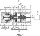
- FIG. 3 is a cross-sectional view illustrating a close-circuit state according to the second embodiment
- FIG. 4 is a cross-sectional view illustrating an open-circuit state according to the second embodiment. Note that the same or similar component as that of the first embodiment will be denoted by the same reference numeral, and the duplicated description will be omitted.
- a plurality of first suction holes 22b is formed in the flange 22d of the movable contact base 22.
- the first suction hole 22b is a hole that communicates the internal space 22a of the movable contact base 22 and the compression chamber 30, and suctions the insulating gas in the internal space 22a into the compression chamber 30 at the time of the circuit closing operation.
- a valve 32 in a ring-plate shape is placed inside the compression chamber 30.
- the valve 32 is fitted in a groove 32a formed in the inner circumference of the movable shield 23, has the restricted movable range by abutting the end portion of the groove 32a.
- the groove 32a is a positioning portion for the valve 32 at the end of the circuit closing operation.
- the valve 32 has a structure to block the first suction holes 22b by pressure difference when the pressure in the compression chamber 30 becomes higher than the pressure in the internal space 22a.
- a circuit opening operation according to the second embodiment that employs the above structure will be described through a transition from a close-circuit state illustrated in FIG. 3 to the open-circuit state illustrated in FIG. 4 .
- the detailed description will be omitted.
- the pressure in the compression chamber 30 becomes higher than the pressure in the internal space 22a because the piston 25a is driven to the right side in FIG. 3 , and the valve 32 blocks the first suction hole 22b (a state in FIG. 4 ). Accordingly, no insulating gas flows in the compression chamber 30 from the internal space 22a through the first suction holes 22b.
- the low-temperature gas in the compression chamber 30 can be efficiently compressed by the driven piston 25a, and the low-temperature gas in the compression chamber 30 can be intensively sprayed toward the fixed arcing contact 11 side via the communication hole 25c, the hollow portion 25b, and the ventilation hole 21a.
- the second embodiment like the first embodiment, since the internal space of the suction chamber 31 expands and the pressure of the insulating gas becomes lower than the surroundings, the insulting gas around the arc-resistant metal 24 is taken in the interior of the suction chamber 31 through the clearance 31a.
- a circuit closing operation according to the second embodiment will be described through a transition from the open-circuit state illustrated in FIG. 4 to the close-circuit state illustrated in FIG. 3 .
- the detailed description will be omitted.
- the pressure in the compression chamber 30 becomes lower than the pressure in the internal space 22a because the piston 25a is driven to the left side in FIG. 4 , and the valve 32 opens the first suction holes 22b.
- the insulating gas in the internal space 22a flows into the compression chamber 30 via the first suction hole 22b, and a pressure reduction by the expansion of the internal space of the compression chamber 30 is suppressed.
- the piston 25a does not become a condition that is difficult to move in the circuit opening direction (the leftward direction in FIG. 4 ) associated with the pressure reduction of the compression chamber 30.
- the valve 32 abuts the end portion of the groove 32a at the end of the circuit closing operation, and the valve 32 is positioned.
- the action and effect similar to the first embodiment can be achieved, and there are the following further unique action and effect. That is, at the time of circuit closing operation, since the valve 32 opens the first suction holes 22b, the insulating gas flows into the compression chamber 30 from the internal space 22a of the movable contact base 22 via the first suction holes 22b. Accordingly, suppression force to the circuit closing operation produced relative to the piston 25a decreases without a pressure reduction of the compression chamber 30.
- the internal space 22a of the movable contact base 22 is adopted as a space for supplying the insulating gas into the compression chamber 30, it is easy to ensure the flow volume of the insulating gas into the compression chamber 30. Moreover, adjustment of the flow volume of the insulating gas is facilitated by changing the size of the first suction holes 22b. Consequently, the circuit closing operation can be executed with the minimum energy, a further reduction of a load on the operation mechanism 5 is advanced, and the current breaking time is further reduced.
- FIG. 5 is a cross-sectional view illustrating a close-circuit state according to the third embodiment
- FIG. 6 is a cross-sectional view illustrating an open-circuit state according to the third embodiment. Note that the same or similar component as that of the first embodiment will be denoted by the same reference numeral, and the duplicated description will be omitted.
- a plurality of second suction holes 25d is formed in the piston 25a.
- the second suction holes 25d communicates the compression chamber 30 and the suction chamber 31, and suctions the insulating gas into the compression chamber 30 at the time of circuit closing operation like the first suction holes 22b.
- the valve 32 in a ring-plate shape is placed inside the compression chamber 30.
- the valve 32 has the movable range restricted by a retainer ring 32b that is fixed to the outer circumference of the operation rod 25.
- the retainer ring 32b is a positioning portion of the valve 32 at the end of the circuit closing operation.
- the valve 32 has a structure that blocks the second suction holes 25d by pressure difference when the pressure in the compression chamber 30 becomes higher than the pressure in the suction chamber 31.
- a circuit opening operation according to the third embodiment that employs the above structure will be described through a transition from the close-circuit state illustrated in FIG. 5 to the open-circuit state illustrated in FIG. 6 .
- the detailed description will be omitted.
- the pressure in the compression chamber 30 becomes higher than the pressure in the suction chamber 31 because the piston 25a is driven to the right side in FIG. 5 , and the valve 32 blocks the second suction holes 25d. Accordingly, no insulating gas flows into the compression chamber 30 from the suction chamber 31 through the second suction holes 25d, and the insulating gas can be efficiently compressed in the compression chamber 30.
- the low-temperature gas in the compression chamber 30 can be intensively sprayed toward the fixed arcing contact 11 from the compression chamber 30 via the communication hole 25c, the hollow portion 25b, and the ventilation hole 21a.
- the internal space of the suction chamber 31 expands, the pressure of the insulating gas becomes lower than the surroundings, and the insulating gas around the arc-resistant metal 24 is taken in the interior of the suction chamber 31 through the clearance 31a.
- a circuit closing operation according to the third embodiment will be described through a transition from the open-circuit state illustrated in FIG. 6 to the close-circuit state illustrated in FIG. 5 .
- the detailed description will be omitted.
- the pressure in the compression chamber 30 becomes lower than the pressure in the suction chamber 31 because the piston 25a is driven to the left side in FIG. 6 , and the valve 32 opens the second suction holes 25d.
- the insulating gas in the suction chamber 31 flows in the compression chamber 30 via the second suction holes 25d, and the insulating gas in the suction chamber 31 decreases and the insulating gas in the compression chamber 30 increases.
- the pressure in the compression chamber 30 and in the suction chamber 31 can be equalized, and a pressure reduction of the compression chamber 30 and a pressure increase of the suction chamber 31 can be simultaneously suppressed. Consequently, the piston 25a does not become a condition that is difficult to move in the circuit closing operation direction (the leftward direction in FIG. 6 ).
- the valve 32 abuts the retainer ring 32b at the end of the circuit closing operation, and the valve 32 is positioned.
- the action and effect similar to those of the first and second embodiments can be achieved, and furthermore, not only the pressure reduction of the compression chamber 30 but also the pressure increase of the suction chamber 31 can be suppressed at the time of circuit closing operation.
- the suppression force to the circuit closing operation produced at the piston 25a can be surely reduced, and the circuit closing operation can be executed by a further smaller energy. Accordingly, a reduction of load on the operation mechanism 5 can be further advanced, and the current breaking time can be efficiently reduced.
- FIG. 7 is a cross-sectional view illustrating a close-circuit state according to the fourth embodiment
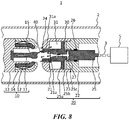
- FIG. 8 is a cross-sectional view illustrating an open-circuit state according to the fourth embodiment. Note that the same or similar component as that of the first embodiment will be denoted by the same reference numeral, and the duplicated description will be omitted.
- the fourth embodiment is a modified example relating to the ventilation hole 21a of the movable contact 21 illustrated in FIGS. 1 and 2 .
- a ventilation hole 21b is formed to increase the flow-channel cross-sectional area for the insulating gas from a portion connected to the hollow portion 25b of the actuation rod 25 toward the end surface of the movable contact 21. That is, the ventilation hole 21b increases the flow-channel cross-sectional area from the portion in communication with the hollow portion 25b toward the portion where the low-temperature gas is sprayed.
- the number of ventilation holes 21b is one.
- the following unique action and effect are achieved. That is, also in the fourth embodiment, the low-temperature gas compressed in the compression chamber 30 at the time of circuit opening operation is sprayed from the ventilation hole 21a via the communication hole 25c and the hollow portion 25b.
- the ventilation hole 21b has the flow-channel cross-sectional area that increases from the portion in communication with the hollow portion 25b toward the spray portion to the fixed arcing contact 11.
- the low-temperature gas that passes through the ventilation hole 21b increases the flow velocity when sprayed to the thermal gas. Accordingly, the thermal gas can be more efficiently cooled, and diffused. Consequently, a further better insulation performance relative to the transient recovery voltage after current breaking can be obtained.
- the shape and dimension of the clearance 31a that is formed along the outer circumference of the movable contact 21, the shape and dimension of the movable contact 21, the number, shape, and dimension of the ventilation hole 21a formed in the movable contact 21, and the number, shape, and dimension of the hollow portion 25b and the communication hole 25c formed in the operation rod 25, etc. can be selected as appropriate, and by simply adjusting the flow volume of the low-temperature gas to be sprayed toward the space where the arc 40 is produced, diffusion and cooling of the thermal gas due to the arc 40 can be efficiently executed.
- the size of the area that covers the communication hole 25c at the end of the circuit opening operation can be changed as appropriate as long as braking of the operation rod 25 and the movable contact 21 is achievable.
Landscapes
- Circuit Breakers (AREA)
- Arc-Extinguishing Devices That Are Switches (AREA)
Abstract
Description
- Embodiments of the present disclosure relate to a gas-insulated switchgear that has improved insulation characteristics.
- A switchgear for a high voltage that has a duty of breaking an accident current in a power system is required to surely break currents from a small current to a large current. In particular, as for a large-current breaking, the following two current breaking duties must be satisfied. One is a duty of breaking a short-distance line fault (SLF) current, and the other is a duty of breaking a breaker terminal short-circuit fault (BTF) current. The SLF current is a current having a voltage in a triangular waveform which has a low absolute value but has a keen change rate at the initial stage of rising of a transient recovery voltage produced immediately after a current zero point. The BTF current is a current to which a voltage having a gentle rise at the initial stage of the transient recovery voltage but has a high absolute value at the final stage.
- Conventionally, a switchgear that accomplishes the above-described two current breaking duties by a single contact unit has been broadly adopted. However, when it is attempted to accomplish the two current breaking duties by a single contact unit, the weight of a movable member in the contact unit becomes heavy, and a load on an operation mechanism that actuates a movable member increases. Hence, a scheme of accomplishment by a single contact unit may be inadequate for an application where a quite-short current breaking time is required.
- In recent years, a reduction of a current breaking time is desired, and there is a request to reduce the weight of the movable member of the contact unit and reduce a load on the operation mechanism. Accordingly, a multipoint current breaking switchgear that includes a plurality of contact units specialized for respective current breaking duties to separately accomplish the above-described two current breaking duties is proposed. In the multipoint current breaking scheme, different types of contact units are electrically connected in series, enabling accomplishment of multiple kinds of current breaking duties. An example known contact unit specialized for a current breaking duty is a vacuum current breaking unit, a gas contact unit, etc.
- A vacuum current breaking unit is a contact unit with excellent current breaking characteristics for a keen voltage change, and breaks an accident current. The gas contact unit is a contact unit with high insulation characteristics, and executes insulation after a current breaking. In multipoint current breaking switchgear that has such two contact units, since the respective contact units share different current breaking duties, the weight of the movable member per each contact unit can be reduced. Hence, a load on the operation mechanism can be reduced, and the current breaking time can be efficiently reduced. Accordingly, the multipoint current breaking switchgear is suitable for an application where a quite-short current breaking time is required.
-
- Patent Document 1:
JP 2015-43656 A - Patent Document 2:
WO 2015/185095 A1 - Patent Document 3:
JP S55-053824 A - Patent Document 4:
JP H8-321233 A - Patent Document 5:
JP 2002-075148 A - Patent Document 6:
JP 2008-112633 A - Patent Document 7:
JP S61-14444 A - Patent Document 8:
JP 2014-72032 A - Patent Document 9:
JP 2015-79635 A - Patent Document 10:
JP 2015-185381 A - Patent Document 11:
JP 2015-185467 A - Patent Document 12:
US Patent No. 5,258,590 - Patent Document 13: US Patent NO.
5,258,590 - According to the multipoint current breaking switchgear, when a vacuum current breaking unit that breaks an accident current, and a gas contact unit that executes insulation after the current breaking are provided as the contact units that share the current breaking duties, there are the following technical problems. That is, when the vacuum current breaking unit extinguishes the accident current, an arc is produced in the vacuum current breaking unit until the accident current is fully dissipated, and not only that, an arc is also produced in the gas contact unit.
- Hence, an insulating gas in the gas contact unit becomes a thermal gas with a high temperature because of the production of arc. This thermal gas remains in the gas contact unit for a long time, even after the arc is extinguished. Consequently, there is a possibility that an insulation performance of the gas contact unit decreases. In particular, when the amount of remaining thermal gas is large, ignition of an arc may occur again in the gas contact unit, which may result in a failure of the current breaking itself.
- Embodiments has been proposed in order to address the above-described technical problems, and an objective is to provide a gas-insulated switchgear which efficiently removes a remaining thermal gas to improve an insulation performance, and which can easily accomplish a current breaking duty required in a switchgear for a high voltage.
- In order to accomplish the above objective, an embodiment of the present disclosure provides a gas-insulated switchgear that includes a pressure chamber in which an insulating gas is gas-tightly filled, a fixed contact base and a movable contact base placed in the pressure chamber so as to face with each other, a fixed arcing contact fixed to the fixed contact base, a fixed shield fixed to the fixed contact base so as to surround the fixed arcing contact, a fixed conductive contact placed at the fixed shield, a movable contact placed so as to face the fixed conductive contact and to be freely movable, a movable shield fixed to the movable contact base so as to surround the movable contact, an operation rod which is connected to the movable contact and to which a piston is fixed, and an operation mechanism that reciprocates the operation rod so as to move the movable contact to be apart or in contact relative to the fixed arcing contact and the fixed conductive contact, in which the following features (1) to (6) are included.
-
- (1) Inside the movable shield, with the piston of the operation rod acting as a partition wall, a compression chamber and a suction chamber are formed at a movable-contact-base side and at the movable-contact side, respectively.
- (2) The operation rod is provided with a hollow portion, and a communication hole that communicates the hollow portion and the compression chamber.
- (3) The movable contact is provided with a ventilation hole that passes completely through from an end surface of the movable contact to the hollow portion of the operation rod.
- (4) The compression chamber compresses the insulating gas therein by a movement of the piston associated with a movement of the operation rod at a time of circuit opening operation, and sprays the insulating gas to an arc produced between the fixed arcing contact and the movable contact via the communication hole, the hollow portion, and the ventilation hole.
- (5) A clearance is provided between an outer circumference of the movable contact and an inner circumference of the movable shield.
- (6) The suction chamber reduces an internal pressure by expanding an internal space by a movement of the piston associated with a movement of the operation rod at a time of circuit opening operation, and sucks the high-temperature insulating gas heated by the arc into the internal space through the clearance.
-
-
FIG. 1 is a cross-sectional view illustrating a close-circuit state of a gas-insulated switchgear according to a first embodiment; -
FIG. 2 is a cross-sectional view illustrating an open-circuit state of the gas-insulated switchgear according to the first embodiment; -
FIG. 3 is a cross-sectional view illustrating a close-circuit state of a gas-insulated switchgear according to a second embodiment; -
FIG. 4 is a cross-sectional view illustrating an open-circuit state of the gas-insulated switchgear according to the second embodiment; -
FIG. 5 is a cross-sectional view illustrating a close-circuit state of a gas-insulated switchgear according to a third embodiment; -
FIG. 6 is a cross-sectional view illustrating an open-circuit state of the gas-insulated switchgear according to the third embodiment; -
FIG. 7 is a cross-sectional view illustrating a close-circuit state of a gas-insulated switchgear according to a fourth embodiment; and -
FIG. 8 is a cross-sectional view illustrating an open-circuit state of the gas-insulated switchgear according to the fourth embodiment. - Embodiments of a gas-insulated switchgear according to the present disclosure will be described below with reference to the drawings. Gas-insulated switchgears to be described in below embodiments all have a plurality of contactors which can share a current breaking duty and which are electrically connected in series, and are applied to a gas contact unit that is a contact unit.
- With reference to
FIGS. 1 and2 , a structure according to a first embodiment will be described.FIG. 1 is a cross-sectional view illustrating a close-circuit state according to the first embodiment, andFIG. 2 is a cross-sectional views illustrating an open-circuit state according to the first embodiment. As illustrated inFIGS. 1 and2 , a gas-insulatedswitchgear 1 is provided with apressure chamber 2 in which an insulating gas is gas-tightly filled. A fixedcontact unit 10 and amovable contact unit 20 are placed in thepressure chamber 2 so as to face with each other. - The
movable contact unit 20 includes amovable shaft 3 that extends out to the exterior of thepressure chamber 2, and themovable shaft 3 is connected to anoperation mechanism 5. Theoperation mechanism 5 is attached to thepressure chamber 2. Theoperation mechanism 5 linearly reciprocates themovable contact unit 20 via themovable shaft 3, and moves themovable contact unit 20 to be apart or in contact relative to the fixedcontact unit 10. - In the following description, end portions of the fixed
contact unit 10 and themovable contact unit 20 that relatively come close to each other are defined as respective tip end portions of thecontactor units FIGS. 1 and2 , in themovable contact unit 20, the right side inFIG. 1 is a basal-end portion side, and the opposite side is a tip-end portion side. In contrast, in the fixedcontact unit 10, the right side inFIG. 1 is a tip-end portion side, and the opposite side is a basal-end portion side. Note that when the tip end portion is an end surface, this will be also referred to as a tip end surface. - The fixed
contact unit 10 includes a fixedarcing contact 11, a fixedconductive contacts 12, a fixedcontact base 13, and a fixedshield 14, all arranged concentrically to one another. Aspring 16 is placed inside the fixedshield 14. - The fixed
contact base 13 is fixed to thepressure chamber 2. The fixedarcing contact 11 in a bar shape is attached to the center part of the fixedcontact base 13. Acylindrical portion 13a that is thinner than the outer diameter of the base 13 protrudes and is formed on the tip end surface of the fixedcontact base 13, and the fixedconductive contact 12 is placed so as to surround thecylindrical portion 13a. - The plurality of fixed
conductive contacts 12 is placed in the circumferential direction, and the tip end portions are bent toward the internal side. The fixedconductive contacts 12 are pushed by thespring 16 in the internal direction, and at the same time abuts the outer circumference of thecylindrical portion 13a of the fixedcontact base 13, and thus the movement toward the internal side by thespring 16 is restricted. - The fixed
shield 14 is fixed to the outer circumference of the fixedcontact base 13 so as to surround the fixedconductive contact 12. The tip end portion of the fixedshield 14 is bent toward the internal side so as to cover the tip end portion of the fixedconductive contact 12. Acircular opening 14a is formed in the tip end portion of the fixedshield 14. - An arc-
resistant metal 15 that has arc-resistant characteristics is firmly attached to the tip end portion of the fixedarcing contact 11. The arc-resistant metal 15 is formed in a spindle shape that expands outwardly. The fixedarcing contact 11 is provided withslit 17 that has tip end portion sides split in the lengthwise direction. The plurality ofslits 17 is provided in parallel with each other. By theseslits 17, the fixedarcing contact 11 has spring characteristics that deforms the tip end portion in the radial direction. - The
movable contact unit 20 includes amovable contact 21, amovable contact base 22, amovable shield 23, and anoperation rod 25, all arranged concentrically to one another. Among these components, theoperation rod 25 has the tip end portion connected to themovable contact 21, and the basal end portion connected to themovable shaft 3. Theoperation rod 25 moves themovable contact 21 to be apart or in contact relative to the fixedarcing contact 11 and the fixedconductive contact 12 due to themovable shaft 3 performing reciprocation movement by theoperation mechanism 5. -
Apiston 25a in a disk shape is fixed to theoperation rod 25. Moreover, ahollow portion 25b that extends in the lengthwise direction is provided in the center part of theoperation rod 25. Furthermore, acommunication hole 25c which is orthogonal to thehollow portion 25b and which reaches the outer circumference of theactuation rod 25 from thehollow portion 25b is provided in theoperation rod 25. Thecommunication hole 25c is a hole that communicates thehollow portion 25b and acompression chamber 30 to be described later. - The
movable contact 21 is attached to the tip end portion of theoperation rod 25, and is placed so as to be freely movable and face the fixed current-carryingcontactor 12 in the lengthwise direction. The outer diameter of themovable contact 21 is formed so as to be smaller than the internal diameter of theopening 14a of the fixedshield 14, so that themovable contact 21 can be inserted in theopening 14a of the fixedshield 14. When themovable contact 21 is inserted in theopening 14a of the fixedshield 14, themovable contact 21 is provided so that the outer circumference is in contact with the inner circumference of the fixedconductive contact 12. - An arc-
resistant metal 24 that has arc-resistant characteristics is firmly attached to the tip end portion of themovable contact 21. The arc-resistant metal 24 is formed in a ring shape so that the arc-resistant metal 15 of the fixedarcing contact 11 is in contact or moves apart relative to the inner circumference. That is, in themovable contact unit 20, theoperation rod 25 andmovable contact 21 are members that move in an circuit opening operation and circuit closing operation. In contrast, themovable contact base 22 is a component that is fixed to thepressure chamber 2, and themovable shield 23 is a component that is fixed to themovable contact base 22 even in themovable contact unit 20. - In the
movable contact 21, at the basal end portion side when viewed from a portion where the arc-resistant metal 15 is inserted, a plurality ofventilation holes 21a each extending in the lengthwise direction of themovable contact 21 is provided. Theventilation hole 21a is a hole that passes completely through from the end surface of themovable contact 21 to thehollow portion 25b of theoperation rod 25. An opening of theventilation hole 21a at the tip end portion side is arranged so as to face the end portion of the arc-resistant metal 15 of the fixedarcing contact 11. - The
movable contact base 22 is fixed to thepressure chamber 2. Themovable contact base 22 is a hollow cylindrical component, and the interior is in communication with aninternal space 22a of thepressure chamber 2. Athick flange 22d is formed at the tip end portion of themovable contact base 22. In the end surface of theflange 22d of themovable contact base 22, a corner portion that faces thecommunication hole 25c of theoperation rod 25 at the end of the circuit opening operation is defined as a gas flowvolume limiting portion 22e. The gas flowvolume limiting portion 22e is provided so as to cover at least a part of thecommunication hole 25c with a predetermined clearance at the end of the circuit opening operation. - A
holder hole 22c is opened at the center of theflange 22d of themovable contact base 22. Theoperation rod 25 is inserted in theholder hole 22c. Aclearance 33 is formed between the inner circumference of theholder hole 22c of themovable contact base 22 and the outer circumference of theoperation rod 25. Thisclearance 33 becomes a gap when the gas flowvolume limiting portion 22e of themovable contact base 22 covers thecommunication hole 25c. - Placed in the
clearance 33 are a collectingcontactor 26 and a slide packing 27 so as to contact the inner circumference of themovable contact base 22 and the outer circumference of theoperation rod 25. In theflange 22d of themovable contact base 22, the collectingcontactor 26 is attached to the basal end portion side, and the slide packing 27 is attached to tip end portion side, respectively. Since the slide packing 27 is installed in theclearance 33, the insulating gas compressed in thecompression chamber 30 does not flow toward theinternal space 22a of themovable contact base 22 through theclearance 33. Moreover, the slide packing 27 is configured to block a part of thecommunication hole 25c of theoperation rod 25 at the end of a circuit opening operation. - The
movable shield 23 is fixed to the outer circumference of theflange 22d of themovable contact base 22, and acircular opening 23a is formed in the tip end surface so as to surround the outer circumference of themovable contact 21. The outer diameter of themovable contact 21 is formed to be smaller than the internal diameter of theopening 23a. Hence, aclearance 31a is formed between the outer circumference of themovable contact 21 and the inner circumference of theopening 23a of themovable shield 23. - Two spaces are formed in the internal space of the
movable shield 23 with thepiston 25a of theoperation rod 25 being a partition wall. One is thecompression chamber 30 formed in themovable contact base 22 side, and the other is asuction chamber 31 formed in themovable contact 21 side. The internal diameter of thecompression chamber 30 is designed to be larger than the internal diameter of thesuction chamber 31. Aclearance 34 is formed between the inner circumference of themovable shield 23 and the outer circumference of thepiston 25a. A slide packing 28 is placed in theclearance 34 so as to contact the inner circumference of themovable shield 23 and the outer circumference of thepiston 25a. - The
compression chamber 30 is a space surrounded by thepiston 25a of theoperation rod 25, the outer circumference of theoperation rod 25, theflange 22d of themovable contact base 22, and the inner circumference of themovable shield 23. Thecompression chamber 30 compresses the insulating gas therein by a movement of thepiston 25a associated with the movement of theoperation rod 25 at the time of the circuit opening operation. Moreover, thecompression chamber 30 sprays the compressed insulating gas to an arc 40 (illustrated inFIG. 2 ) produced between the arc-resistant metal 15 of the fixedarcing contact 11 side and the arc-resistant metal 24 of themovable contact 21 side through thecommunication hole 25c, thehollow portion 25b, and the plurality ofventilation holes 21a. Note that since the insulating gas in thecompression chamber 30 has a low temperature in comparison with a thermal gas, the insulating gas in thecompression chamber 30 will be referred to as a low-temperature gas. - The
suction chamber 31 is a space surrounded by thepiston 25a of theoperation rod 25, the outer circumference of theoperation rod 25, the outer circumference of themovable contact 21, and the inner circumference of themovable shield 23. Thesuction chamber 31 decreases the pressure in the chamber by an expansion of the internal space due to the movement of thepiston 25a associated with the movement of theoperation rod 25 at the time of the circuit opening operation, and suctions a high-temperature insulating gas (will be referred to as a thermal gas below) heated by thearc 40 in the chamber through theclearance 31a, . - The circuit opening operation according to the first embodiment that employs the above-described structure will be described through a transition from a close-circuit state illustrated in
FIG. 1 to an open-circuit state illustrated inFIG. 2 . First, in the close-circuit state illustrated inFIG. 1 , themovable contact 21 is in contact with the fixedarcing contact 11 and with the fixedconductive contact 12, and is in a conduction state. - In the close-circuit state, the fixed
conductive contact 12 is pushed against the outer circumference of themovable contact 21 by the elastic force of thespring 16. Moreover, in the close-circuit state, since the fixedarcing contact 11 deforms to shrink in the radial direction by the plurality ofslits 17, the arc-resistant metal 15 firmly attached to the tip end portion of the fixedarcing contact 11 is pushed in the outer circumference direction, and is pressed against the inner circumference of themovable contact 21. - With the above-described close-circuit state being an initial state, when the
operation mechanism 5 is activated by a circuit opening command transmitted from the exterior and themovable shaft 3 is driven to the right side inFIG. 1 , theoperation rod 25 and themovable contact 21 are also driven to the right side. Hence, themovable contact 21 becomes apart first from the fixedconductive contact 12. At this time, since the fixedarcing contact 11 is in contact with themovable contact 21, noarc 40 is produced between themovable contact 21 and the fixedconductive contact 12. - Subsequently, when circuit opening operation advances and the
movable contact 21 becomes apart from the fixedarcing contact 11, the arc 40 (illustrated inFIG. 2 ) is produced between the arc-resistant metal 24 of themovable contact 21 side and the arc-resistant metal 15 of the fixedarcing contact 11 side. Since thearc 40 is in extremely high temperature, the insulating gas therearound becomes the high-temperature thermal gas, and remains between the fixedarcing contact 11 and themovable contact 21. - When the circuit opening operation further advances, an accident current is broken by the other switchgear (unillustrated) that is connected in series with the gas-insulated
switchgear 1. Hence, thearc 40 produced between the fixedarcing contact 11 and themovable contact 21 extinguishes. However, even when thearc 40 is extinguished, the thermal gas due to thearc 40 still remains between the fixedarcing contact 11 and themovable contact 21. Hence, it is in a state in which the insulation performance relative to the transient recovery voltage after the current breaking is decreased. - Hence, according to the first embodiment, in order to suppress the reduction of the insulation performance, the following operation is executed. That is, in the circuit opening operation, the
piston 25a that is driven to the right side associated with the movement of theoperation rod 25 compresses the low-temperature gas in thecompression chamber 30. The low-temperature gas compressed in thecompression chamber 30 passes through thecommunication hole 25c, thehollow portion 25b, and the plurality ofventilation holes 21a in sequence, and is sprayed between the fixedarcing contact 11 and themovable contact 21. - Moreover, in the circuit opening operation, the internal space of the
suction chamber 31 expands because thepiston 25a has moved to the right side, and the pressure of the insulating gas in the chamber becomes lower than the surroundings. At this time, the internal space of thesuction chamber 31 and the space where thearc 40 is produced are in communication with each other by theclearance 31a provided between the outer circumference of themovable contact 21 and the inner circumference of theopening 23a of themovable shield 23. Hence, the thermal gas present around the arc-resistant metal 24 and themovable contact 21 can be taken into thesuction chamber 31 via theclearance 31a. - At the end of the circuit opening operation, the gas flow
volume limiting portion 22e provided in the end surface of theflange 22d of themovable contact base 22 covers at least a part of thecommunication hole 25c of theoperation rod 25, and the slide packing 27 blocks a part of thecommunication hole 25c (a state illustrated inFIG. 2 ). The circuit opening operation ends when the state transitions to the state inFIG. 2 from the state inFIG. 1 . At the end of the circuit opening operation, themovable contact 21 is completely retained in themovable shield 23. - Next, a circuit closing operation of the gas-insulated
switchgear 1 illustrated inFIG. 2 where a transition to the close-circuit state illustrated inFIG. 1 from the open-circuit state occurs will be described. First, in the open-circuit state illustrated inFIG. 2 , themovable contact 21 moves apart from the fixedarcing contact 11 and the fixedconductive contact 12, and is in non-conductive state. - With the above-described open-circuit state being an initial state, when the
operation mechanism 5 is activated by a circuit closing command transmitted from the exterior and themovable shaft 3 is driven to the left side inFIG. 2 , theoperation rod 25 and themovable contact 21 are driven to the left side, and themovable contact 21 is closed and in contact with the fixedarcing contact 11, and then is closed and in contact with the fixed conductive contact 12fixed arcing contact. - Since the
piston 25a is driven to the left side inFIG. 2 as the circuit closing operation advances, the internal space of thecompression chamber 30 expands, and the pressure of the insulating gas becomes lower than the surroundings. Hence, the insulating gas around the fixedarcing contact 11 is taken into thecompression chamber 30 through thecommunication hole 25c, thehollow portion 25b, and theventilation hole 21a. - Moreover, by driving the
piston 25a to the left side inFIG. 2 , the insulating gas in thesuction chamber 31 is compressed, and the insulating gas is sprayed toward the arc-resistant metal 24 side of themovable contact 21 via theclearance 31a. The circuit closing operation ends when the state transitions to the state inFIG. 1 from the state inFIG. 2 , and themovable contact 21 is closed and in contact with the fixedarcing contact 11 and the fixedconductive contact 12, and is in the conductive state. -
- (1) According to the first embodiment, in the
compression chamber 30, the insulating gas in the chamber is compressed by the movement of thepiston 25a assocaited with the movement of theoperation rod 25 at the time of the circuit opening operation, and the low-temperature gas is sprayed to thearc 40 via thecommunication hole 25c, thehollow portion 25b, and the plurality ofventilation holes 21a. At this time, the plurality ofventilation holes 21a faces a portion where the arc-resistant metal 15 of the fixedarcing contact 11 is inserted.
Hence, theventilation hole 21a can intensively spray a large amount of low-temperature gas from thecompression chamber 30 to the thermal gas due to thearc 40. Accordingly, the thermal gas due to thearc 40 can be cooled efficiently, and the remaining thermal gas can be diffused all around from the space where thearc 40 is produced, and can be blown away from between the fixedarcing contact 11 and themovable contact 21.
In addition, according to the first embodiment, since thepiston 25a that starts moving compresses the insulating gas in thecompression chamber 30, the low-temperature gas can be sprayed toward the space where thearc 40 is produced from the initial stage of the circuit opening operation. Therefore, the thermal gas can be promptly diffused, contributing to an improvement in insulation performance.
According to the first embodiment, simultaneously with the above-described diffusion of the thermal gas, the thermal gas due to thearc 40 can be suctioned by thesuction chamber 31. Hence, the thermal gas can be efficiently removed from between the fixedarcing contact 11 and themovable contact 21. At this time, theclearance 31a that becomes a flow channel for the thermal gas to thesuction chamber 31 is located at the outer circumference of themovable contact 21.
Accordingly, the thermal gas diffused along the outer circumference of themovable contact 21 by the sprayed low-temperature gas can smoothly flow toward theclearance 31a. Moreover, according to the first embodiment, since the pressure in thesuction chamber 31 decreases by thepiston 25a that starts moving, thesuction chamber 31 can quickly suction the thermal gas through theclearance 31a from the initial stage of the circuit opening operation.
As described above, according to the gas-insulatedswitchgear 1 of the first embodiment, since the thermal gas is removed from between the fixedarcing contact 11 and themovable contact 21, re-ignition of the fixedarcing contact 11 and themovable contact 21 hardly occurs. Accordingly, an excellent insulation performance relative to the transient recovery voltage after the current breaking can be obtained. Hence, the gas-insulatedswitchgear 1 can easily achieve the current breaking duty required for a switchgear for a high voltage, and reduces a load on theoperation mechanism 5, contributing to a reduction of a current breaking time. - (2) According to the first embodiment, since the gas flow
volume limiting portion 22e of theflange 22d of themovable contact base 22 covers at least a part of thecommunication hole 25c of theoperation rod 25 at the end of the circuit opening operation, the cross-sectional area of thecommunication hole 25c in communication with thecompression chamber 30 decreases. Accordingly, immediately before the end of the circuit opening operation, the flow volume of the low-temperature gas that flows toward theventilation hole 21a from thecompression chamber 30 can be reduced, and the internal pressure of thecompression chamber 30 increases.
Consequently, puffer reaction force that acts in the direction opposite to the driving direction in the circuit opening operation, that is, the leftward direction inFIG. 2 to thepiston 25a increases, and theoperation rod 25 and to themovable contact 21 can be braked immediately before the end of the circuit opening operation. This can ease a shock produced when the circuit opening operation ends, and the operational reliability can be improved. - (3) According to the first embodiment, at the end of the circuit opening operation, the slide packing 27 blocks only a part of the
communication hole 25c of theoperation rod 25. That is, thecommunication hole 25c is not completely blocked by the slide packing 27. Accordingly, as described in the previous paragraph, although the flow volume of the low-temperature gas from thecompression chamber 30 is reduced immediately before the end of the circuit opening operation, the flow volume does not become completely zero, and the low-temperature gas is degassed from thecompression chamber 30 to theventilation hole 21a through thecommunication hole 25c.
Consequently, immediately before the end of the circuit opening operation, even if the internal pressure of thecompression chamber 30 increases by the reduction of the flow volume of the low-temperature gas, the pressure in thecompression chamber 30 does not excessively increase. Hence, at the end of the circuit opening operation, thepiston 25a is prevented from moving in the opposite side to the left side inFIG. 2 because of the puffer reaction force. - (4) According to the first embodiment, immediately before the end of the circuit closing operation, the internal space of the
compression chamber 30 expands and the pressure of the insulating gas becomes lower than the surroundings. Conversely, in thesuction chamber 31, the pressure becomes higher than the surroundings, and the puffer reaction force that is in the direction opposite to the driving direction in the circuit closing operation, that is, the rightward direction inFIG. 1 acts on thepiston 25a. Accordingly, the braking force can be surely applied to theoperation rod 25 and themovable contact 21 can be surely braked immediately before the end of the circuit closing operation, and a shock produced when the circuit closing operation ends can be eased. - (5) According to the first embodiment, the
spring 16 pushes the fixedconductive contact 12 against the outer circumference of themovable contact 21. Hence, an electrical resistance decreases, and heat generation by conduction can be suppressed. Moreover, the fixedarcing contact 11 deforms so as to shrink in the radial direction by the plurality ofslits 17 to have elastic force in the outer circumference direction, and thus the fixedarcing contact 11 is pushed against the inner circumference of themovable contact 21. Hence, like the fixedconductive contact 12, the electrical resistance decreases, and there is an advantage that heat generation by conduction is suppressed. - A structure according to a second embodiment will be described with reference to
FIGS. 3 and4 .FIG. 3 is a cross-sectional view illustrating a close-circuit state according to the second embodiment, andFIG. 4 is a cross-sectional view illustrating an open-circuit state according to the second embodiment. Note that the same or similar component as that of the first embodiment will be denoted by the same reference numeral, and the duplicated description will be omitted. - According to the second embodiment, a plurality of
first suction holes 22b is formed in theflange 22d of themovable contact base 22. Thefirst suction hole 22b is a hole that communicates theinternal space 22a of themovable contact base 22 and thecompression chamber 30, and suctions the insulating gas in theinternal space 22a into thecompression chamber 30 at the time of the circuit closing operation. - A
valve 32 in a ring-plate shape is placed inside thecompression chamber 30. Thevalve 32 is fitted in agroove 32a formed in the inner circumference of themovable shield 23, has the restricted movable range by abutting the end portion of thegroove 32a. Thegroove 32a is a positioning portion for thevalve 32 at the end of the circuit closing operation. Thevalve 32 has a structure to block the first suction holes 22b by pressure difference when the pressure in thecompression chamber 30 becomes higher than the pressure in theinternal space 22a. - A circuit opening operation according to the second embodiment that employs the above structure will be described through a transition from a close-circuit state illustrated in
FIG. 3 to the open-circuit state illustrated inFIG. 4 . However, as for the same feature as that of the circuit opening operation in the first embodiment, the detailed description will be omitted. - At the time of the circuit opening operation, the pressure in the
compression chamber 30 becomes higher than the pressure in theinternal space 22a because thepiston 25a is driven to the right side inFIG. 3 , and thevalve 32 blocks thefirst suction hole 22b (a state inFIG. 4 ). Accordingly, no insulating gas flows in thecompression chamber 30 from theinternal space 22a through thefirst suction holes 22b. - Accordingly, the low-temperature gas in the
compression chamber 30 can be efficiently compressed by the drivenpiston 25a, and the low-temperature gas in thecompression chamber 30 can be intensively sprayed toward the fixedarcing contact 11 side via thecommunication hole 25c, thehollow portion 25b, and theventilation hole 21a. Moreover, according to the second embodiment, like the first embodiment, since the internal space of thesuction chamber 31 expands and the pressure of the insulating gas becomes lower than the surroundings, the insulting gas around the arc-resistant metal 24 is taken in the interior of thesuction chamber 31 through theclearance 31a. - A circuit closing operation according to the second embodiment will be described through a transition from the open-circuit state illustrated in
FIG. 4 to the close-circuit state illustrated inFIG. 3 . However, as for the same feature as that of the circuit closing operation according to the first embodiment, the detailed description will be omitted. - In the circuit closing operation, the pressure in the
compression chamber 30 becomes lower than the pressure in theinternal space 22a because thepiston 25a is driven to the left side inFIG. 4 , and thevalve 32 opens thefirst suction holes 22b. Hence, the insulating gas in theinternal space 22a flows into thecompression chamber 30 via thefirst suction hole 22b, and a pressure reduction by the expansion of the internal space of thecompression chamber 30 is suppressed. Accordingly, thepiston 25a does not become a condition that is difficult to move in the circuit opening direction (the leftward direction inFIG. 4 ) associated with the pressure reduction of thecompression chamber 30. Thevalve 32 abuts the end portion of thegroove 32a at the end of the circuit closing operation, and thevalve 32 is positioned. - According to the second embodiment, the action and effect similar to the first embodiment can be achieved, and there are the following further unique action and effect. That is, at the time of circuit closing operation, since the
valve 32 opens thefirst suction holes 22b, the insulating gas flows into thecompression chamber 30 from theinternal space 22a of themovable contact base 22 via thefirst suction holes 22b. Accordingly, suppression force to the circuit closing operation produced relative to thepiston 25a decreases without a pressure reduction of thecompression chamber 30. - In addition, according to the second embodiment, since the
internal space 22a of themovable contact base 22 is adopted as a space for supplying the insulating gas into thecompression chamber 30, it is easy to ensure the flow volume of the insulating gas into thecompression chamber 30. Moreover, adjustment of the flow volume of the insulating gas is facilitated by changing the size of thefirst suction holes 22b. Consequently, the circuit closing operation can be executed with the minimum energy, a further reduction of a load on theoperation mechanism 5 is advanced, and the current breaking time is further reduced. - A structure according to a third embodiment will be described with reference to
FIGS. 5 and6 .FIG. 5 is a cross-sectional view illustrating a close-circuit state according to the third embodiment, andFIG. 6 is a cross-sectional view illustrating an open-circuit state according to the third embodiment. Note that the same or similar component as that of the first embodiment will be denoted by the same reference numeral, and the duplicated description will be omitted. - According to the third embodiment, a plurality of
second suction holes 25d is formed in thepiston 25a. Thesecond suction holes 25d communicates thecompression chamber 30 and thesuction chamber 31, and suctions the insulating gas into thecompression chamber 30 at the time of circuit closing operation like thefirst suction holes 22b. - The
valve 32 in a ring-plate shape is placed inside thecompression chamber 30. Thevalve 32 has the movable range restricted by aretainer ring 32b that is fixed to the outer circumference of theoperation rod 25. Theretainer ring 32b is a positioning portion of thevalve 32 at the end of the circuit closing operation. Furthermore, thevalve 32 has a structure that blocks thesecond suction holes 25d by pressure difference when the pressure in thecompression chamber 30 becomes higher than the pressure in thesuction chamber 31. - A circuit opening operation according to the third embodiment that employs the above structure will be described through a transition from the close-circuit state illustrated in
FIG. 5 to the open-circuit state illustrated inFIG. 6 . However, as for the same feature as that of the circuit opening operation in the first embodiment, the detailed description will be omitted. - At the time of the circuit opening operation, the pressure in the
compression chamber 30 becomes higher than the pressure in thesuction chamber 31 because thepiston 25a is driven to the right side inFIG. 5 , and thevalve 32 blocks thesecond suction holes 25d. Accordingly, no insulating gas flows into thecompression chamber 30 from thesuction chamber 31 through thesecond suction holes 25d, and the insulating gas can be efficiently compressed in thecompression chamber 30. - Accordingly, the low-temperature gas in the
compression chamber 30 can be intensively sprayed toward the fixedarcing contact 11 from thecompression chamber 30 via thecommunication hole 25c, thehollow portion 25b, and theventilation hole 21a. Furthermore, according to the third embodiment, like the first and second embodiments, the internal space of thesuction chamber 31 expands, the pressure of the insulating gas becomes lower than the surroundings, and the insulating gas around the arc-resistant metal 24 is taken in the interior of thesuction chamber 31 through theclearance 31a. - A circuit closing operation according to the third embodiment will be described through a transition from the open-circuit state illustrated in
FIG. 6 to the close-circuit state illustrated inFIG. 5 . However, as for the same feature as that of the circuit closing operation according to the first embodiment, the detailed description will be omitted. - At the time of the circuit closing operation, the pressure in the
compression chamber 30 becomes lower than the pressure in thesuction chamber 31 because thepiston 25a is driven to the left side inFIG. 6 , and thevalve 32 opens thesecond suction holes 25d. Hence, the insulating gas in thesuction chamber 31 flows in thecompression chamber 30 via thesecond suction holes 25d, and the insulating gas in thesuction chamber 31 decreases and the insulating gas in thecompression chamber 30 increases. - Accordingly, the pressure in the
compression chamber 30 and in thesuction chamber 31 can be equalized, and a pressure reduction of thecompression chamber 30 and a pressure increase of thesuction chamber 31 can be simultaneously suppressed. Consequently, thepiston 25a does not become a condition that is difficult to move in the circuit closing operation direction (the leftward direction inFIG. 6 ). Thevalve 32 abuts theretainer ring 32b at the end of the circuit closing operation, and thevalve 32 is positioned. - According to the third embodiment, the action and effect similar to those of the first and second embodiments can be achieved, and furthermore, not only the pressure reduction of the
compression chamber 30 but also the pressure increase of thesuction chamber 31 can be suppressed at the time of circuit closing operation. Hence, in the circuit closing operation, the suppression force to the circuit closing operation produced at thepiston 25a can be surely reduced, and the circuit closing operation can be executed by a further smaller energy. Accordingly, a reduction of load on theoperation mechanism 5 can be further advanced, and the current breaking time can be efficiently reduced. - A structure according to a fourth embodiment will be described with reference to
FIGS. 7 and8 .FIG. 7 is a cross-sectional view illustrating a close-circuit state according to the fourth embodiment, andFIG. 8 is a cross-sectional view illustrating an open-circuit state according to the fourth embodiment. Note that the same or similar component as that of the first embodiment will be denoted by the same reference numeral, and the duplicated description will be omitted. - The fourth embodiment is a modified example relating to the
ventilation hole 21a of themovable contact 21 illustrated inFIGS. 1 and2 . A ventilation hole 21b is formed to increase the flow-channel cross-sectional area for the insulating gas from a portion connected to thehollow portion 25b of theactuation rod 25 toward the end surface of themovable contact 21. That is, the ventilation hole 21b increases the flow-channel cross-sectional area from the portion in communication with thehollow portion 25b toward the portion where the low-temperature gas is sprayed. In to the fourth embodiment, the number of ventilation holes 21b is one. - According to the above fourth embodiment, in addition to the action and effect similar to those of the first embodiment, the following unique action and effect are achieved. That is, also in the fourth embodiment, the low-temperature gas compressed in the
compression chamber 30 at the time of circuit opening operation is sprayed from theventilation hole 21a via thecommunication hole 25c and thehollow portion 25b. - At this time, the ventilation hole 21b has the flow-channel cross-sectional area that increases from the portion in communication with the
hollow portion 25b toward the spray portion to the fixedarcing contact 11. Hence, the low-temperature gas that passes through the ventilation hole 21b increases the flow velocity when sprayed to the thermal gas. Accordingly, the thermal gas can be more efficiently cooled, and diffused. Consequently, a further better insulation performance relative to the transient recovery voltage after current breaking can be obtained. - Several embodiments of the present disclosure have been described, but those embodiments are merely presented as examples, and are not intended to limit the scope of the present disclosure. Those embodiments can be carried out in other various forms, and various omissions, replacements, and modifications can be made without departing from the scope of the present disclosure. Such embodiments and modified forms thereof are within the scope of the present disclosure, and also within the scope of the invention as recited in appended claims and equivalent range thereto.
- For example, the shape and dimension of the
clearance 31a that is formed along the outer circumference of themovable contact 21, the shape and dimension of themovable contact 21, the number, shape, and dimension of theventilation hole 21a formed in themovable contact 21, and the number, shape, and dimension of thehollow portion 25b and thecommunication hole 25c formed in theoperation rod 25, etc., can be selected as appropriate, and by simply adjusting the flow volume of the low-temperature gas to be sprayed toward the space where thearc 40 is produced, diffusion and cooling of the thermal gas due to thearc 40 can be efficiently executed. Moreover, in the end surface of themovable contact base 22 and the slide packing 27, the size of the area that covers thecommunication hole 25c at the end of the circuit opening operation can be changed as appropriate as long as braking of theoperation rod 25 and themovable contact 21 is achievable. -
- 1
- Gas-insulated switchgear
- 2
- Pressure chamber
- 3
- Movable shaft
- 5
- Operation mechanism
- 10
- Fixed contact unit
- 11
- Fixed arcing contact
- 12
- Fixed conductive contact
- 13
- Fixed contact base
- 13a
- Cylindrical portion
- 14
- Fixed shield
- 14a, 23a
- Opening
- 15, 24
- Arc-resistant metal
- 17
- Slit
- 20
- Movable contact unit
- 21
- Movable contact
- 21a, 21b
- Ventilation hole
- 22
- Movable contact base
- 22a
- Internal space
- 22b
- First suction hole
- 22c
- Holder hole
- 22d
- Flange
- 22e
- Gas flow volume limiting portion
- 23
- Movable shield
- 25
- operation rod
- 25a
- Piston
- 25b
- Hollow portion
- 25c
- Communication hole
- 25d
- Second suction hole
- 26
- Collecting contactor
- 27, 28
- Slide packing
- 30
- Compression chamber
- 31
- Suction chamber
- 31a, 33, 34
- Clearance
- 32
- Valve
- 32a
- Groove
- 32b
- Retainer ring
- 40
- Arc
Claims (10)
- A gas-insulated switchgear comprising:a pressure chamber in which an insulating gas is gas-tightly filled;a fixed contact base and a movable contact base placed in the pressure chamber so as to face with each other;a fixed arcing contact fixed to the fixed contact base;a fixed shield fixed to the fixed contact base so as to surround the fixed arcing contact;a fixed conductive contact placed at the fixed shield;a movable contact placed so as to face the fixed conductive contact and to be freely movable;a movable shield fixed to the movable contact base so as to surround the movable contact;an operation rod which is connected to the movable contact and to which a piston is fixed; andan operation mechanism that reciprocates the operation rod so as to move the movable contact to be apart or in contact relative to the fixed arcing contact and the fixed conductive contact, wherein:inside the movable shield, with the piston of the operation rod being a partition wall, a compression chamber and a suction chamber are formed at a movable-contact-base side and at the movable-contact side, respectively;the operation rod is provided with a hollow portion, and a communication hole that communicates the hollow portion and the compression chamber;the movable contact is provided with a ventilation hole that passes completely through from an end surface of the movable contact to the hollow portion of the operation rod;the compression chamber compresses the insulating gas therein by a movement of the piston associated with a movement of the operation rod at a time of circuit opening operation, and sprays the insulating gas to an arc produced between the fixed arcing contact and the movable contact via the communication hole, the hollow portion, and the ventilation hole;a clearance is provided between an outer circumference of the movable contact and an inner circumference of the movable shield; andthe suction chamber reduces an internal pressure by expanding an internal space by a movement of the piston associated with a movement of the operation rod at a time of circuit opening operation, and suctions the high-temperature insulating gas heated by the arc into the internal space through the clearance.
- The gas-insulated switchgear according to claim 1, wherein:a first suction hole to suction the insulating gas into the compression chamber at the time of circuit closing operation is formed in an end surface of the movable contact base facing with the compression chamber; anda valve which blocks the first suction hole at the time of circuit opening operation and which opens the first suction hole at the time of circuit closing operation is attached to the first suction hole.
- The gas-insulated switchgear according to claim 1 or 2, wherein:a second suction hole which communicates the suction chamber and the compression chamber, and which is to suction the insulating gas in the suction chamber into the compression chamber at the time of circuit closing operation is formed in the piston; anda valve which block the second suction hole at the time of circuit opening operation and which opens the second suction hole at the time of circuit closing operation is attached to the second suction hole.
- The gas-insulated switchgear according to claim 2 or 3, wherein the valve is placed in the compression chamber.
- The gas-insulated switchgear according to any one of claims 2 to 4, further comprising a valve positioning portion that positions the valve at an end of the circuit closing operation.
- The gas-insulated switchgear according to any one of claims 1 to 5, wherein the ventilation hole is formed so as to increase a flow-channel cross-sectional area for the insulating gas from a portion connected to the hollow portion of the operation rod toward an end surface of the movable contact.
- The gas-insulated switchgear according to any one of claims 1 to 6, wherein a plurality of the ventilation holes is formed.
- The gas-insulated switchgear according to any one of claims 1 to 7, wherein at least either the fixed arcing contact or the fixed conductor contactor is pushed toward the movable contact.
- The gas-insulated switchgear according to any one of claims 1 to 7, wherein a gas flow volume limiting portion which covers at least a part of the communication hole at an end of the circuit opening operation is provided at an end surface of the movable contact base.
- The gas-insulated switchgear according to any one of claims 1 to 9, further comprising a slide packing placed so as to contact an inner circumference of the movable contact base and an outer circumference of the operation rod,
wherein the slide packing is configured to block a part of the communication hole of the operation rod at an end of the circuit opening operation.
Applications Claiming Priority (1)
| Application Number | Priority Date | Filing Date | Title |
|---|---|---|---|
| PCT/JP2016/087587 WO2018109931A1 (en) | 2016-12-16 | 2016-12-16 | Gas-insulation switch device |
Publications (3)
| Publication Number | Publication Date |
|---|---|
| EP3561840A1 true EP3561840A1 (en) | 2019-10-30 |
| EP3561840A4 EP3561840A4 (en) | 2020-08-19 |
| EP3561840B1 EP3561840B1 (en) | 2024-07-10 |
Family
ID=62558270
Family Applications (1)
| Application Number | Title | Priority Date | Filing Date |
|---|---|---|---|
| EP16923924.1A Active EP3561840B1 (en) | 2016-12-16 | 2016-12-16 | Gas-insulation switch device |
Country Status (4)
| Country | Link |
|---|---|
| EP (1) | EP3561840B1 (en) |
| JP (1) | JP6823082B2 (en) |
| CN (1) | CN110088866B (en) |
| WO (1) | WO2018109931A1 (en) |
Families Citing this family (2)
| Publication number | Priority date | Publication date | Assignee | Title |
|---|---|---|---|---|
| US11380501B2 (en) * | 2019-12-31 | 2022-07-05 | Southern States Llc | High voltage electric power switch with carbon arcing electrodes and carbon dioxide dielectric gas |
| KR102877948B1 (en) * | 2021-12-27 | 2025-10-28 | 엘에스일렉트릭(주) | Gas Insulated Switchgear |
Family Cites Families (23)
| Publication number | Priority date | Publication date | Assignee | Title |
|---|---|---|---|---|
| JPS5553824A (en) | 1978-10-17 | 1980-04-19 | Mitsubishi Electric Corp | Gas switch |
| JPS58100326A (en) * | 1981-12-10 | 1983-06-15 | 株式会社東芝 | Buffer type gas breaker |
| JPS6114444A (en) | 1984-06-30 | 1986-01-22 | Nec Home Electronics Ltd | Air-fuel ratio control system |
| JPH0214741U (en) * | 1988-07-15 | 1990-01-30 | ||
| JP2512502Y2 (en) * | 1988-12-02 | 1996-10-02 | 株式会社高岳製作所 | Gas insulated disconnector |
| JPH03116638U (en) * | 1990-03-14 | 1991-12-03 | ||
| FR2680044B1 (en) | 1991-08-02 | 1995-01-20 | Alsthom Gec | MEDIUM OR HIGH VOLTAGE CIRCUIT BREAKER WITH ARC-END CONTACTORS. |
| JPH0553094U (en) * | 1991-12-24 | 1993-07-13 | 株式会社東芝 | Gas insulated ground switch |
| DE19517615A1 (en) | 1995-05-13 | 1996-11-14 | Abb Research Ltd | Circuit breaker |
| JP2002075148A (en) | 2000-08-31 | 2002-03-15 | Hitachi Ltd | Puffer type gas circuit breaker |
| JP2008112633A (en) | 2006-10-30 | 2008-05-15 | Mitsubishi Electric Corp | Gas circuit breaker |
| ATE549731T1 (en) * | 2009-07-21 | 2012-03-15 | Abb Technology Ag | HIGH VOLTAGE SWITCH |
| JP5389279B2 (en) * | 2011-01-07 | 2014-01-15 | 三菱電機株式会社 | Switchgear |
| JP5516568B2 (en) * | 2011-12-28 | 2014-06-11 | 株式会社日立製作所 | Puffer type gas circuit breaker |
| JP6157824B2 (en) | 2012-09-28 | 2017-07-05 | 株式会社東芝 | Gas circuit breaker |
| TW201442051A (en) * | 2013-03-08 | 2014-11-01 | Hitachi Ltd | Gas blast circuit breaker |
| JP2015043656A (en) | 2013-08-26 | 2015-03-05 | 株式会社東芝 | Circuit breaker |
| JP6289856B2 (en) | 2013-10-16 | 2018-03-07 | 株式会社東芝 | Gas circuit breaker |
| JP6382543B2 (en) | 2014-03-24 | 2018-08-29 | 株式会社東芝 | Gas circuit breaker |
| JP6320106B2 (en) | 2014-03-25 | 2018-05-09 | 株式会社東芝 | Gas circuit breaker |
| EP3149757B1 (en) | 2014-06-02 | 2018-08-08 | ABB Schweiz AG | High voltage puffer breaker and a circuit breaker unit comprising such a puffer breaker |
| KR101632978B1 (en) * | 2014-06-26 | 2016-06-24 | 현대중공업 주식회사 | Gas insulated circuit breaker |
| CN105023800B (en) * | 2015-07-08 | 2018-01-26 | 平高集团有限公司 | Double acting arc-chutes, breaker and Cubicle Gas-Insulated Switchgear |
-
2016
- 2016-12-16 CN CN201680091563.3A patent/CN110088866B/en active Active
- 2016-12-16 JP JP2018556149A patent/JP6823082B2/en active Active
- 2016-12-16 EP EP16923924.1A patent/EP3561840B1/en active Active
- 2016-12-16 WO PCT/JP2016/087587 patent/WO2018109931A1/en not_active Ceased
Also Published As
| Publication number | Publication date |
|---|---|
| JP6823082B2 (en) | 2021-02-03 |
| CN110088866B (en) | 2021-11-19 |
| WO2018109931A1 (en) | 2018-06-21 |
| EP3561840A4 (en) | 2020-08-19 |
| EP3561840B1 (en) | 2024-07-10 |
| CN110088866A (en) | 2019-08-02 |
| JPWO2018109931A1 (en) | 2019-10-24 |
Similar Documents
| Publication | Publication Date | Title |
|---|---|---|
| CN112074923B (en) | Gas-insulated medium-voltage switchgear with shielding device | |
| US10354821B2 (en) | Gas circuit breaker | |
| EP3561840B1 (en) | Gas-insulation switch device | |
| US8766131B2 (en) | Gas-insulated high-voltage switch | |
| JP2018098128A (en) | Gas insulated switchgear | |
| CN102034640A (en) | Circuit breaker with parallel rated current paths | |
| US11062862B2 (en) | Gas-insulated high or medium voltage circuit breaker | |
| EP4141901B1 (en) | Metal enclosed circuit breaker | |
| EP4476753B1 (en) | Fast earthing switch for interrupting non-short-circuit currents | |
| EP4117006B1 (en) | Gas-insulated high or medium voltage circuit breaker | |
| JP2015082368A (en) | Gas circuit breaker | |
| EP4125108B1 (en) | Gas-insulated high or medium voltage circuit breaker | |
| EP4345858A1 (en) | A switch, a load break switch and a switchgear | |
| JP6084506B2 (en) | Sliding member for gas circuit breaker and gas circuit breaker using the same | |
| JP2010061858A (en) | Gas-blast circuit breaker | |
| JP2017034921A (en) | Switchgear | |
| JP6736345B2 (en) | Gas circuit breaker | |
| JP2020155302A (en) | Gas circuit breaker | |
| JP2014002868A (en) | Gas-blast circuit breaker | |
| JP2013171803A (en) | Gas circuit breaker | |
| CN112673445A (en) | Gas insulated switch | |
| JP2017068997A (en) | Gas circuit breaker |
Legal Events
| Date | Code | Title | Description |
|---|---|---|---|
| STAA | Information on the status of an ep patent application or granted ep patent |
Free format text: STATUS: THE INTERNATIONAL PUBLICATION HAS BEEN MADE |
|
| PUAI | Public reference made under article 153(3) epc to a published international application that has entered the european phase |
Free format text: ORIGINAL CODE: 0009012 |
|
| STAA | Information on the status of an ep patent application or granted ep patent |
Free format text: STATUS: REQUEST FOR EXAMINATION WAS MADE |
|
| 17P | Request for examination filed |
Effective date: 20190715 |
|
| AK | Designated contracting states |
Kind code of ref document: A1 Designated state(s): AL AT BE BG CH CY CZ DE DK EE ES FI FR GB GR HR HU IE IS IT LI LT LU LV MC MK MT NL NO PL PT RO RS SE SI SK SM TR |
|
| AX | Request for extension of the european patent |
Extension state: BA ME |
|
| DAV | Request for validation of the european patent (deleted) | ||
| DAX | Request for extension of the european patent (deleted) | ||
| A4 | Supplementary search report drawn up and despatched |
Effective date: 20200722 |
|
| RIC1 | Information provided on ipc code assigned before grant |
Ipc: H01H 33/91 20060101ALI20200716BHEP Ipc: H01H 33/90 20060101ALI20200716BHEP Ipc: H01H 33/88 20060101ALI20200716BHEP Ipc: H01H 33/04 20060101AFI20200716BHEP |
|
| STAA | Information on the status of an ep patent application or granted ep patent |
Free format text: STATUS: EXAMINATION IS IN PROGRESS |
|
| 17Q | First examination report despatched |
Effective date: 20221025 |
|
| GRAP | Despatch of communication of intention to grant a patent |
Free format text: ORIGINAL CODE: EPIDOSNIGR1 |
|
| STAA | Information on the status of an ep patent application or granted ep patent |
Free format text: STATUS: GRANT OF PATENT IS INTENDED |
|
| INTG | Intention to grant announced |
Effective date: 20240318 |
|
| GRAS | Grant fee paid |
Free format text: ORIGINAL CODE: EPIDOSNIGR3 |
|
| GRAA | (expected) grant |
Free format text: ORIGINAL CODE: 0009210 |
|
| STAA | Information on the status of an ep patent application or granted ep patent |
Free format text: STATUS: THE PATENT HAS BEEN GRANTED |
|
| AK | Designated contracting states |
Kind code of ref document: B1 Designated state(s): AL AT BE BG CH CY CZ DE DK EE ES FI FR GB GR HR HU IE IS IT LI LT LU LV MC MK MT NL NO PL PT RO RS SE SI SK SM TR |
|
| REG | Reference to a national code |
Ref country code: CH Ref legal event code: EP |
|
| REG | Reference to a national code |
Ref country code: DE Ref legal event code: R096 Ref document number: 602016088392 Country of ref document: DE |
|
| REG | Reference to a national code |
Ref country code: SE Ref legal event code: TRGR |
|
| REG | Reference to a national code |
Ref country code: LT Ref legal event code: MG9D |
|
| REG | Reference to a national code |
Ref country code: NL Ref legal event code: MP Effective date: 20240710 |
|
| PG25 | Lapsed in a contracting state [announced via postgrant information from national office to epo] |
Ref country code: PT Free format text: LAPSE BECAUSE OF FAILURE TO SUBMIT A TRANSLATION OF THE DESCRIPTION OR TO PAY THE FEE WITHIN THE PRESCRIBED TIME-LIMIT Effective date: 20241111 |
|
| REG | Reference to a national code |
Ref country code: AT Ref legal event code: MK05 Ref document number: 1702804 Country of ref document: AT Kind code of ref document: T Effective date: 20240710 |
|
| PG25 | Lapsed in a contracting state [announced via postgrant information from national office to epo] |
Ref country code: NL Free format text: LAPSE BECAUSE OF FAILURE TO SUBMIT A TRANSLATION OF THE DESCRIPTION OR TO PAY THE FEE WITHIN THE PRESCRIBED TIME-LIMIT Effective date: 20240710 |
|
| PG25 | Lapsed in a contracting state [announced via postgrant information from national office to epo] |
Ref country code: PT Free format text: LAPSE BECAUSE OF FAILURE TO SUBMIT A TRANSLATION OF THE DESCRIPTION OR TO PAY THE FEE WITHIN THE PRESCRIBED TIME-LIMIT Effective date: 20241111 Ref country code: NL Free format text: LAPSE BECAUSE OF FAILURE TO SUBMIT A TRANSLATION OF THE DESCRIPTION OR TO PAY THE FEE WITHIN THE PRESCRIBED TIME-LIMIT Effective date: 20240710 |
|
| PG25 | Lapsed in a contracting state [announced via postgrant information from national office to epo] |
Ref country code: NO Free format text: LAPSE BECAUSE OF FAILURE TO SUBMIT A TRANSLATION OF THE DESCRIPTION OR TO PAY THE FEE WITHIN THE PRESCRIBED TIME-LIMIT Effective date: 20241010 |
|
| PG25 | Lapsed in a contracting state [announced via postgrant information from national office to epo] |
Ref country code: PL Free format text: LAPSE BECAUSE OF FAILURE TO SUBMIT A TRANSLATION OF THE DESCRIPTION OR TO PAY THE FEE WITHIN THE PRESCRIBED TIME-LIMIT Effective date: 20240710 Ref country code: GR Free format text: LAPSE BECAUSE OF FAILURE TO SUBMIT A TRANSLATION OF THE DESCRIPTION OR TO PAY THE FEE WITHIN THE PRESCRIBED TIME-LIMIT Effective date: 20241011 Ref country code: FI Free format text: LAPSE BECAUSE OF FAILURE TO SUBMIT A TRANSLATION OF THE DESCRIPTION OR TO PAY THE FEE WITHIN THE PRESCRIBED TIME-LIMIT Effective date: 20240710 |
|
| PG25 | Lapsed in a contracting state [announced via postgrant information from national office to epo] |
Ref country code: BG Free format text: LAPSE BECAUSE OF FAILURE TO SUBMIT A TRANSLATION OF THE DESCRIPTION OR TO PAY THE FEE WITHIN THE PRESCRIBED TIME-LIMIT Effective date: 20240710 |
|
| PG25 | Lapsed in a contracting state [announced via postgrant information from national office to epo] |
Ref country code: LV Free format text: LAPSE BECAUSE OF FAILURE TO SUBMIT A TRANSLATION OF THE DESCRIPTION OR TO PAY THE FEE WITHIN THE PRESCRIBED TIME-LIMIT Effective date: 20240710 |
|
| PG25 | Lapsed in a contracting state [announced via postgrant information from national office to epo] |
Ref country code: IS Free format text: LAPSE BECAUSE OF FAILURE TO SUBMIT A TRANSLATION OF THE DESCRIPTION OR TO PAY THE FEE WITHIN THE PRESCRIBED TIME-LIMIT Effective date: 20241110 Ref country code: AT Free format text: LAPSE BECAUSE OF FAILURE TO SUBMIT A TRANSLATION OF THE DESCRIPTION OR TO PAY THE FEE WITHIN THE PRESCRIBED TIME-LIMIT Effective date: 20240710 |
|
| PG25 | Lapsed in a contracting state [announced via postgrant information from national office to epo] |
Ref country code: HR Free format text: LAPSE BECAUSE OF FAILURE TO SUBMIT A TRANSLATION OF THE DESCRIPTION OR TO PAY THE FEE WITHIN THE PRESCRIBED TIME-LIMIT Effective date: 20240710 |
|
| PG25 | Lapsed in a contracting state [announced via postgrant information from national office to epo] |
Ref country code: ES Free format text: LAPSE BECAUSE OF FAILURE TO SUBMIT A TRANSLATION OF THE DESCRIPTION OR TO PAY THE FEE WITHIN THE PRESCRIBED TIME-LIMIT Effective date: 20240710 Ref country code: RS Free format text: LAPSE BECAUSE OF FAILURE TO SUBMIT A TRANSLATION OF THE DESCRIPTION OR TO PAY THE FEE WITHIN THE PRESCRIBED TIME-LIMIT Effective date: 20241010 |
|
| PG25 | Lapsed in a contracting state [announced via postgrant information from national office to epo] |
Ref country code: RS Free format text: LAPSE BECAUSE OF FAILURE TO SUBMIT A TRANSLATION OF THE DESCRIPTION OR TO PAY THE FEE WITHIN THE PRESCRIBED TIME-LIMIT Effective date: 20241010 Ref country code: PL Free format text: LAPSE BECAUSE OF FAILURE TO SUBMIT A TRANSLATION OF THE DESCRIPTION OR TO PAY THE FEE WITHIN THE PRESCRIBED TIME-LIMIT Effective date: 20240710 Ref country code: NO Free format text: LAPSE BECAUSE OF FAILURE TO SUBMIT A TRANSLATION OF THE DESCRIPTION OR TO PAY THE FEE WITHIN THE PRESCRIBED TIME-LIMIT Effective date: 20241010 Ref country code: LV Free format text: LAPSE BECAUSE OF FAILURE TO SUBMIT A TRANSLATION OF THE DESCRIPTION OR TO PAY THE FEE WITHIN THE PRESCRIBED TIME-LIMIT Effective date: 20240710 Ref country code: IS Free format text: LAPSE BECAUSE OF FAILURE TO SUBMIT A TRANSLATION OF THE DESCRIPTION OR TO PAY THE FEE WITHIN THE PRESCRIBED TIME-LIMIT Effective date: 20241110 Ref country code: HR Free format text: LAPSE BECAUSE OF FAILURE TO SUBMIT A TRANSLATION OF THE DESCRIPTION OR TO PAY THE FEE WITHIN THE PRESCRIBED TIME-LIMIT Effective date: 20240710 Ref country code: GR Free format text: LAPSE BECAUSE OF FAILURE TO SUBMIT A TRANSLATION OF THE DESCRIPTION OR TO PAY THE FEE WITHIN THE PRESCRIBED TIME-LIMIT Effective date: 20241011 Ref country code: FI Free format text: LAPSE BECAUSE OF FAILURE TO SUBMIT A TRANSLATION OF THE DESCRIPTION OR TO PAY THE FEE WITHIN THE PRESCRIBED TIME-LIMIT Effective date: 20240710 Ref country code: ES Free format text: LAPSE BECAUSE OF FAILURE TO SUBMIT A TRANSLATION OF THE DESCRIPTION OR TO PAY THE FEE WITHIN THE PRESCRIBED TIME-LIMIT Effective date: 20240710 Ref country code: BG Free format text: LAPSE BECAUSE OF FAILURE TO SUBMIT A TRANSLATION OF THE DESCRIPTION OR TO PAY THE FEE WITHIN THE PRESCRIBED TIME-LIMIT Effective date: 20240710 Ref country code: AT Free format text: LAPSE BECAUSE OF FAILURE TO SUBMIT A TRANSLATION OF THE DESCRIPTION OR TO PAY THE FEE WITHIN THE PRESCRIBED TIME-LIMIT Effective date: 20240710 |
|
| REG | Reference to a national code |
Ref country code: DE Ref legal event code: R097 Ref document number: 602016088392 Country of ref document: DE |
|
| PG25 | Lapsed in a contracting state [announced via postgrant information from national office to epo] |
Ref country code: SM Free format text: LAPSE BECAUSE OF FAILURE TO SUBMIT A TRANSLATION OF THE DESCRIPTION OR TO PAY THE FEE WITHIN THE PRESCRIBED TIME-LIMIT Effective date: 20240710 Ref country code: RO Free format text: LAPSE BECAUSE OF FAILURE TO SUBMIT A TRANSLATION OF THE DESCRIPTION OR TO PAY THE FEE WITHIN THE PRESCRIBED TIME-LIMIT Effective date: 20240710 Ref country code: DK Free format text: LAPSE BECAUSE OF FAILURE TO SUBMIT A TRANSLATION OF THE DESCRIPTION OR TO PAY THE FEE WITHIN THE PRESCRIBED TIME-LIMIT Effective date: 20240710 |
|
| PG25 | Lapsed in a contracting state [announced via postgrant information from national office to epo] |
Ref country code: EE Free format text: LAPSE BECAUSE OF FAILURE TO SUBMIT A TRANSLATION OF THE DESCRIPTION OR TO PAY THE FEE WITHIN THE PRESCRIBED TIME-LIMIT Effective date: 20240710 |
|
| PG25 | Lapsed in a contracting state [announced via postgrant information from national office to epo] |
Ref country code: CZ Free format text: LAPSE BECAUSE OF FAILURE TO SUBMIT A TRANSLATION OF THE DESCRIPTION OR TO PAY THE FEE WITHIN THE PRESCRIBED TIME-LIMIT Effective date: 20240710 |
|
| PG25 | Lapsed in a contracting state [announced via postgrant information from national office to epo] |
Ref country code: IT Free format text: LAPSE BECAUSE OF FAILURE TO SUBMIT A TRANSLATION OF THE DESCRIPTION OR TO PAY THE FEE WITHIN THE PRESCRIBED TIME-LIMIT Effective date: 20240710 Ref country code: SK Free format text: LAPSE BECAUSE OF FAILURE TO SUBMIT A TRANSLATION OF THE DESCRIPTION OR TO PAY THE FEE WITHIN THE PRESCRIBED TIME-LIMIT Effective date: 20240710 |
|
| PLBE | No opposition filed within time limit |
Free format text: ORIGINAL CODE: 0009261 |
|
| STAA | Information on the status of an ep patent application or granted ep patent |
Free format text: STATUS: NO OPPOSITION FILED WITHIN TIME LIMIT |
|
| 26N | No opposition filed |
Effective date: 20250411 |
|
| PG25 | Lapsed in a contracting state [announced via postgrant information from national office to epo] |
Ref country code: MC Free format text: LAPSE BECAUSE OF FAILURE TO SUBMIT A TRANSLATION OF THE DESCRIPTION OR TO PAY THE FEE WITHIN THE PRESCRIBED TIME-LIMIT Effective date: 20240710 |
|
| REG | Reference to a national code |
Ref country code: CH Ref legal event code: PL |
|
| PG25 | Lapsed in a contracting state [announced via postgrant information from national office to epo] |
Ref country code: LU Free format text: LAPSE BECAUSE OF NON-PAYMENT OF DUE FEES Effective date: 20241216 |
|
| REG | Reference to a national code |
Ref country code: BE Ref legal event code: MM Effective date: 20241231 |
|
| PG25 | Lapsed in a contracting state [announced via postgrant information from national office to epo] |
Ref country code: BE Free format text: LAPSE BECAUSE OF NON-PAYMENT OF DUE FEES Effective date: 20241231 |
|
| PG25 | Lapsed in a contracting state [announced via postgrant information from national office to epo] |
Ref country code: FR Free format text: LAPSE BECAUSE OF NON-PAYMENT OF DUE FEES Effective date: 20241231 |
|
| PG25 | Lapsed in a contracting state [announced via postgrant information from national office to epo] |
Ref country code: CH Free format text: LAPSE BECAUSE OF NON-PAYMENT OF DUE FEES Effective date: 20241231 |
|
| PG25 | Lapsed in a contracting state [announced via postgrant information from national office to epo] |
Ref country code: IE Free format text: LAPSE BECAUSE OF NON-PAYMENT OF DUE FEES Effective date: 20241216 |
|
| PGFP | Annual fee paid to national office [announced via postgrant information from national office to epo] |
Ref country code: DE Payment date: 20250930 Year of fee payment: 10 |
|
| PGFP | Annual fee paid to national office [announced via postgrant information from national office to epo] |
Ref country code: GB Payment date: 20251001 Year of fee payment: 10 |
|
| PGFP | Annual fee paid to national office [announced via postgrant information from national office to epo] |
Ref country code: SE Payment date: 20251001 Year of fee payment: 10 |
|
| PG25 | Lapsed in a contracting state [announced via postgrant information from national office to epo] |
Ref country code: CY Free format text: LAPSE BECAUSE OF FAILURE TO SUBMIT A TRANSLATION OF THE DESCRIPTION OR TO PAY THE FEE WITHIN THE PRESCRIBED TIME-LIMIT Effective date: 20240710 |