EP3561839A1 - Switching device - Google Patents
Switching device Download PDFInfo
- Publication number
- EP3561839A1 EP3561839A1 EP18168981.1A EP18168981A EP3561839A1 EP 3561839 A1 EP3561839 A1 EP 3561839A1 EP 18168981 A EP18168981 A EP 18168981A EP 3561839 A1 EP3561839 A1 EP 3561839A1
- Authority
- EP
- European Patent Office
- Prior art keywords
- roll
- actuator
- control shaft
- roll element
- switching device
- Prior art date
- Legal status (The legal status is an assumption and is not a legal conclusion. Google has not performed a legal analysis and makes no representation as to the accuracy of the status listed.)
- Granted
Links
- 230000001419 dependent effect Effects 0.000 description 2
- 238000010891 electric arc Methods 0.000 description 1
Images


Classifications
-
- H—ELECTRICITY
- H01—ELECTRIC ELEMENTS
- H01H—ELECTRIC SWITCHES; RELAYS; SELECTORS; EMERGENCY PROTECTIVE DEVICES
- H01H19/00—Switches operated by an operating part which is rotatable about a longitudinal axis thereof and which is acted upon directly by a solid body external to the switch, e.g. by a hand
- H01H19/02—Details
- H01H19/10—Movable parts; Contacts mounted thereon
- H01H19/20—Driving mechanisms allowing angular displacement of the operating part to be effective in either direction
- H01H19/24—Driving mechanisms allowing angular displacement of the operating part to be effective in either direction acting with snap action
-
- H—ELECTRICITY
- H01—ELECTRIC ELEMENTS
- H01H—ELECTRIC SWITCHES; RELAYS; SELECTORS; EMERGENCY PROTECTIVE DEVICES
- H01H19/00—Switches operated by an operating part which is rotatable about a longitudinal axis thereof and which is acted upon directly by a solid body external to the switch, e.g. by a hand
- H01H19/02—Details
- H01H19/08—Bases; Stationary contacts mounted thereon
-
- H—ELECTRICITY
- H01—ELECTRIC ELEMENTS
- H01H—ELECTRIC SWITCHES; RELAYS; SELECTORS; EMERGENCY PROTECTIVE DEVICES
- H01H19/00—Switches operated by an operating part which is rotatable about a longitudinal axis thereof and which is acted upon directly by a solid body external to the switch, e.g. by a hand
- H01H19/02—Details
- H01H19/10—Movable parts; Contacts mounted thereon
- H01H19/14—Operating parts, e.g. turn knob
-
- H—ELECTRICITY
- H01—ELECTRIC ELEMENTS
- H01H—ELECTRIC SWITCHES; RELAYS; SELECTORS; EMERGENCY PROTECTIVE DEVICES
- H01H3/00—Mechanisms for operating contacts
- H01H3/32—Driving mechanisms, i.e. for transmitting driving force to the contacts
- H01H3/40—Driving mechanisms, i.e. for transmitting driving force to the contacts using friction, toothed, or screw-and-nut gearing
-
- H—ELECTRICITY
- H01—ELECTRIC ELEMENTS
- H01H—ELECTRIC SWITCHES; RELAYS; SELECTORS; EMERGENCY PROTECTIVE DEVICES
- H01H3/00—Mechanisms for operating contacts
- H01H3/32—Driving mechanisms, i.e. for transmitting driving force to the contacts
- H01H3/42—Driving mechanisms, i.e. for transmitting driving force to the contacts using cam or eccentric
-
- H—ELECTRICITY
- H01—ELECTRIC ELEMENTS
- H01H—ELECTRIC SWITCHES; RELAYS; SELECTORS; EMERGENCY PROTECTIVE DEVICES
- H01H2235/00—Springs
- H01H2235/01—Spiral spring
Definitions
- the present invention relates to a switching device according to the preamble of the independent claim 1.
- An object of the present invention is to provide a switching device so as to solve the above problem.
- the objects of the invention are achieved by a switching device which is characterized by what is stated in the independent claim.
- the preferred embodiments of the invention are disclosed in the dependent claims.
- the invention is based on the idea of providing a switching device with at least one roll spring connected between a frame of the switching device and a roll element of the switching device, the at least one roll spring being adapted to rotate the roll element further from the position corresponding to the ON-state during an opening event.
- the roll element of the switching device according to the present invention is adapted to be rotated during an opening event first with at least one actuator spring operationally connected to the roll element through an actuator, and subsequently with the at least one roll spring connected between the frame and the roll element.
- An advantage of the switching device of the invention is that there is a large clearance angle between positions of the roll element corresponding to an ON-state and an OFF-state of switch contacts. Due to the large clearance angle, the present invention enables reducing size of a switching device assembly. The large clearance angle provides adequate clearance between open switch contacts with smaller physical dimensions than a small clearance angle.
- Figure 1 shows a switching device comprising a frame 2, a roll element 4 rotatable between a first position and a second position relative to the frame 2, a control shaft 6 rotatable between an ON-position and an OFF-position relative to the frame 2, and a drive system.
- the roll element 4 is adapted to transfer from the first position to the second position in an opening event for transferring a switch contact system from an ON-state to an OFF-state.
- the control shaft 6 is adapted to control rotation of the roll element 4 such that rotating the control shaft 6 from the ON-position to the OFF-position carries out the opening event.
- the drive system operationally connects the control shaft 6 to the roll element 4 for rotating the roll element 4.
- the control shaft 6 extends through an upper part 21 of the frame 2, and is adapted to be rotated by a user.
- the control shaft 6 is adapted to be connected to an operating handle (not shown) which is adapted to be operated by the user.
- FIG 2 shows a switching device assembly comprising the switching device of Figure 1 and two pole modules 70.
- a switch contact system of the switching device assembly is located in the pole modules 70.
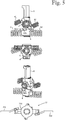
- Figure 3 shows an exploded view of the switching device of Figure 1 from one direction
- Figure 4 shows the exploded view from another direction.
- the exploded views show that the drive system comprises an actuator 8, two actuator springs 81 and 82, two roll springs 41 and 42, a shaft cam 65, a roll cam 45 and a free motion spring 10.
- Each of the actuator springs 81 and 82 is a coils spring. Each of the actuator springs 81 and 82 is connected between the frame 2 and the actuator 8, and has a first low energy position, a second low energy position, and a dead-centre position located between the low energy positions. A spring constant of each of the actuator springs 81 and 82 is high. Each of the actuator springs 81 and 82 is adapted to be transferred both from the first low energy position to the dead-centre position and from the second low energy position to the dead-centre position by means of rotation of the control shaft 6 such that energy required for transferring the actuator springs 81 and 82 to the dead-centre position originates from the rotation of the control shaft 6.
- Each of the actuator springs 81 and 82 is adapted to transfer from the dead-centre position to the first low energy position in a first actuator trip event.
- the drive system is adapted to rotate the roll element 4 towards the second position during the opening event by means of energy delivered by the first actuator trip event.
- the actuator 8 is adapted to be rotated around an axis of rotation relative to the frame 2, and to co-operate with the roll element 4 for rotating the roll element 4 towards the second position during the opening event.
- the actuator 8 and the actuator springs 81 and 82 are located in a lower part 22 of the frame 2.
- the actuator 8 comprises a first actuator protrusion 851 and a second actuator protrusion 852 which are adapted to co-operate with a roll protrusion 405 provided on the roll element 4 for transferring torque from the actuator 8 to the roll element 4.
- the drive system is adapted to rotate the roll element 4 during the opening event to an intermediate position located between the first position and the second position by means of a mechanical contact between the first actuator protrusion 851 and the roll protrusion 405.
- the roll element 4 is provided with a connection system comprising a first connection member 401 on one axial end of the roll element 4, and a second connection member 402 on the other axial end of the roll element 4.
- Each of the connection members 401 and 402 is adapted to connect the roll element 4 to a roll element of a corresponding pole module 70.
- the roll element 4 is adapted to be connected to a switch contact system by means of the connection system for transferring the switch contact system between an ON-state and an OFF-state.
- a rotation axis of the control shaft 6 is perpendicular to a rotation axis of the roll element 4.
- a rotation axis of the actuator 8 coincides with the rotation axis of the control shaft 6.
- the control shaft 6 extends through the roll element 4.
- Each of the roll springs 41 and 42 is a coil spring.
- Each of the roll springs 41 and 42 has a first low energy position, a second low energy position, and a dead-centre position located between the low energy positions.
- Each of the roll springs 41 and 42 is adapted to transfer from the dead-centre position to the first low energy position in a first roll trip event.
- the roll springs 41 and 42 are adapted to rotate the roll element 4 to the second position during the opening event by means of energy delivered by the first roll trip event.
- a spring constant of each of the roll springs 41 and 42 is selected such that a torque adapted to be provided by the roll springs 41 and 42 to the roll element 4 is smaller than a torque adapted to be provided by the actuator springs 81 and 82 to the roll element 4 through the actuator 8.
- the shaft cam 65 protrudes from the control shaft 6.
- the roll cam 45 protrudes from the roll element 4.
- the roll element 4 is adapted to transfer from the second position to the first position in a closing event for transferring a switch contact system from the OFF-state to the ON-state.
- the shaft cam 65 is adapted to co-operate with the roll cam 45 during the closing event for rotating the roll element 4 from the second position towards the first position.
- the drive system is adapted such that during the closing event rotation of the control shaft 6 towards the ON-position first starts to rotate the roll element 4 towards the first position by means of cooperation between the shaft cam 65 and the roll cam 45, and later starts to rotate the actuator 8 by means of a mechanical contact between the control shaft 6 and the actuator 8.
- Each of the actuator springs 81 and 82 is adapted to transfer from the dead-centre position to the second low energy position in a second actuator trip event.
- the drive system is adapted to rotate the roll element 4 towards the first position during the closing event by means of energy delivered by the second actuator trip event.
- the control shaft 6 is connected to the actuator 8 through the free motion spring 10 such that the control shaft 6 is rotatable relative to the actuator 8 between a rest position in which the free motion spring 10 is in a low energy position, and an engagement position in which the free motion spring 10 is in a tensioned position.
- the free motion spring 10 is adapted to attempt to transfer the control shaft 6 to the rest position if the control shaft 6 is deflected therefrom.
- a spring constant of the free motion spring 10 is low.
- a torque adapted to be provided by the actuator springs 81 and 82 to the actuator 8 is multiple compared to a torque adapted to be provided by the free motion spring 10 between the control shaft and the actuator 8.
- Figures 5 to 9 show a mechanism of the switching device of Figure 1 in different stages of an opening event.
- Figure 5 shows the mechanism in a starting position of the opening event.
- Figures 6 to 8 show the mechanism in different positions between the starting position and an end position of the opening event.
- Figure 9 shows the mechanism in the end position of the opening event.
- Figures 5 to 9 show positions of a switch contact system 77 connected to the roll element 4 of the mechanism.
- control shaft 6 is in the ON-position located 90° clockwise relative to the OFF-position which is considered as a reference position herein.
- the roll element 4 is held in the first position by the roll springs 41 and 42.
- the roll springs 41 and 42 are in the second low energy position.
- the actuator springs 81 and 82 are in the second low energy position.
- the free motion spring 10 is in the low energy position.
- the switch contact system 77 is in the ON-state in which a rotatable contact member 703 electrically conductively connects a first stationary contact member 701 to a second stationary contact member 702.
- control shaft 6 has been rotated counterclockwise to a 45° position relative to the OFF-position.
- the control shaft 6 has rotated the actuator 8 to a position in which the actuator springs 81 and 82 are in their dead-centre position in which they store more energy than in the second low energy position.
- the first actuator protrusion 851 has reached a contact with the roll protrusion 405.
- the roll element 4 and the switch contact system 77 are in the same position as in Figure 5 .
- the second position of the roll element 4 is located at a 100° angle relative to the first position of the roll element 4.
- a clearance angle between the first position and the second position is greater than or equal to 65°.
- the intermediate position of the roll element 4 is located at a 50° angle relative to the second position of the roll element 4. In an alternative embodiment an intermediate angle between the intermediate position and the second position is greater than or equal to 20°.
- Figures 10 and 11 show the mechanism in different positions between the starting position and an end position of the closing event. In addition to the mechanism itself, Figures 10 and 11 show positions of the switch contact system 77 connected to the roll element 4 of the mechanism. In the end position of the closing event the mechanism is in the position shown in Figure 5 and described above.
- control shaft 6 is in an 80° position.
- the actuator 8 has rotated 45° by means of a mechanical contact between the control shaft 6 and the actuator 8.
- the actuator springs 81 and 82 are in their dead-centre position.
- the roll springs 41 and 42 are close to their dead-centre position.
- the free motion spring 10 is in the tensioned position, and the control shaft 6 is in the engagement position relative to the actuator 8.
- the second actuator protrusion 852 is almost in a contact with the roll protrusion 405.
- the roll element 4 is in a 50° angle relative to the second position, and therefore the switch contact system 77 is halfway between the OFF-state and the ON-state.
- the shaft cam 65 is still in contact with the roll cam 45.
- an angle velocity of the roll element 4 has been user dependent. In other words the user has been able to decide the angle velocity of the roll element 4 from the second position towards the first position.
- the control shaft 6 has rotated from the 80° position to the 90° position.
- the second actuator trip event begins, and the roll element 4 is started to be rotated towards the first position by means of energy delivered by the second actuator trip event.
- the roll element 4 is rotated by the contact between the second actuator protrusion 852 and the roll protrusion 405.
- rotation of the roll element 4 is completely independent from the user.
- This user independent movement comprises the last 50° of the rotation of the roll element 4 towards the first position.
- An angle velocity of the roll element 4 during the last 50° of the rotation towards the first position is high and depends on the actuator springs 81 and 82 and the roll springs 41 and 42.
Landscapes
- Rotary Switch, Piano Key Switch, And Lever Switch (AREA)
- Mechanisms For Operating Contacts (AREA)
- Closing And Opening Devices For Wings, And Checks For Wings (AREA)
- Vehicle Body Suspensions (AREA)
Abstract
Description
- The present invention relates to a switching device according to the preamble of the independent claim 1.
- An example of a known switching device is described in publication
EP1719142 . - One of the problems associated with the above mentioned known switching device is that a clearance angle between positions of a roll element corresponding to an ON-state and an OFF-state of switch contacts is relatively small, approximately 45°.
- An object of the present invention is to provide a switching device so as to solve the above problem. The objects of the invention are achieved by a switching device which is characterized by what is stated in the independent claim. The preferred embodiments of the invention are disclosed in the dependent claims.
- The invention is based on the idea of providing a switching device with at least one roll spring connected between a frame of the switching device and a roll element of the switching device, the at least one roll spring being adapted to rotate the roll element further from the position corresponding to the ON-state during an opening event. The roll element of the switching device according to the present invention is adapted to be rotated during an opening event first with at least one actuator spring operationally connected to the roll element through an actuator, and subsequently with the at least one roll spring connected between the frame and the roll element.
- An advantage of the switching device of the invention is that there is a large clearance angle between positions of the roll element corresponding to an ON-state and an OFF-state of switch contacts. Due to the large clearance angle, the present invention enables reducing size of a switching device assembly. The large clearance angle provides adequate clearance between open switch contacts with smaller physical dimensions than a small clearance angle.
- In the following the invention will be described in greater detail by means of preferred embodiments with reference to the attached drawings, in which
-
Figure 1 shows a switching device according to an embodiment of the invention; -
Figure 2 shows a switching device assembly comprising the switching device ofFigure 1 and two pole modules; -
Figure 3 shows an exploded view of the switching device ofFigure 1 from one direction; -
Figure 4 shows an exploded view of the switching device ofFigure 1 from another direction; -
Figure 5 shows a mechanism of the switching device ofFigure 1 in a starting position of an opening event which is also an end position of a closing event; -
Figures 6 to 8 show the mechanism of the switching device ofFigure 1 during the opening event, in different positions between the starting position and an end position of the opening event; -
Figure 9 shows the mechanism of the switching device ofFigure 1 in the end position of an opening event which is also a starting position of the closing event; and -
Figures 10 and11 show the mechanism of the switching device ofFigure 1 during the closing event, in different positions between the starting position and the end position of the closing event. -
Figure 1 shows a switching device comprising aframe 2, a roll element 4 rotatable between a first position and a second position relative to theframe 2, acontrol shaft 6 rotatable between an ON-position and an OFF-position relative to theframe 2, and a drive system. The roll element 4 is adapted to transfer from the first position to the second position in an opening event for transferring a switch contact system from an ON-state to an OFF-state. Thecontrol shaft 6 is adapted to control rotation of the roll element 4 such that rotating thecontrol shaft 6 from the ON-position to the OFF-position carries out the opening event. The drive system operationally connects thecontrol shaft 6 to the roll element 4 for rotating the roll element 4. Thecontrol shaft 6 extends through anupper part 21 of theframe 2, and is adapted to be rotated by a user. Thecontrol shaft 6 is adapted to be connected to an operating handle (not shown) which is adapted to be operated by the user. -
Figure 2 shows a switching device assembly comprising the switching device ofFigure 1 and twopole modules 70. A switch contact system of the switching device assembly is located in thepole modules 70. -
Figure 3 shows an exploded view of the switching device ofFigure 1 from one direction, andFigure 4 shows the exploded view from another direction. The exploded views show that the drive system comprises anactuator 8, twoactuator springs roll springs shaft cam 65, aroll cam 45 and afree motion spring 10. - Each of the
actuator springs actuator springs frame 2 and theactuator 8, and has a first low energy position, a second low energy position, and a dead-centre position located between the low energy positions. A spring constant of each of theactuator springs actuator springs control shaft 6 such that energy required for transferring theactuator springs control shaft 6. - Each of the
actuator springs - The
actuator 8 is adapted to be rotated around an axis of rotation relative to theframe 2, and to co-operate with the roll element 4 for rotating the roll element 4 towards the second position during the opening event. Theactuator 8 and theactuator springs lower part 22 of theframe 2. Theactuator 8 comprises afirst actuator protrusion 851 and asecond actuator protrusion 852 which are adapted to co-operate with aroll protrusion 405 provided on the roll element 4 for transferring torque from theactuator 8 to the roll element 4. The drive system is adapted to rotate the roll element 4 during the opening event to an intermediate position located between the first position and the second position by means of a mechanical contact between thefirst actuator protrusion 851 and theroll protrusion 405. - The roll element 4 is provided with a connection system comprising a
first connection member 401 on one axial end of the roll element 4, and asecond connection member 402 on the other axial end of the roll element 4. Each of theconnection members corresponding pole module 70. In other words the roll element 4 is adapted to be connected to a switch contact system by means of the connection system for transferring the switch contact system between an ON-state and an OFF-state. - A rotation axis of the
control shaft 6 is perpendicular to a rotation axis of the roll element 4. A rotation axis of theactuator 8 coincides with the rotation axis of thecontrol shaft 6. Thecontrol shaft 6 extends through the roll element 4. - Each of the
roll springs roll springs roll springs roll springs roll springs roll springs actuator springs actuator 8. - The
shaft cam 65 protrudes from thecontrol shaft 6. Theroll cam 45 protrudes from the roll element 4. - The roll element 4 is adapted to transfer from the second position to the first position in a closing event for transferring a switch contact system from the OFF-state to the ON-state. The
shaft cam 65 is adapted to co-operate with theroll cam 45 during the closing event for rotating the roll element 4 from the second position towards the first position. The drive system is adapted such that during the closing event rotation of thecontrol shaft 6 towards the ON-position first starts to rotate the roll element 4 towards the first position by means of cooperation between theshaft cam 65 and theroll cam 45, and later starts to rotate theactuator 8 by means of a mechanical contact between thecontrol shaft 6 and theactuator 8. - Each of the
actuator springs - The
control shaft 6 is connected to theactuator 8 through thefree motion spring 10 such that thecontrol shaft 6 is rotatable relative to theactuator 8 between a rest position in which thefree motion spring 10 is in a low energy position, and an engagement position in which thefree motion spring 10 is in a tensioned position. Thefree motion spring 10 is adapted to attempt to transfer thecontrol shaft 6 to the rest position if thecontrol shaft 6 is deflected therefrom. - A spring constant of the
free motion spring 10 is low. A torque adapted to be provided by the actuator springs 81 and 82 to theactuator 8 is multiple compared to a torque adapted to be provided by thefree motion spring 10 between the control shaft and theactuator 8. -
Figures 5 to 9 show a mechanism of the switching device ofFigure 1 in different stages of an opening event.Figure 5 shows the mechanism in a starting position of the opening event.Figures 6 to 8 show the mechanism in different positions between the starting position and an end position of the opening event.Figure 9 shows the mechanism in the end position of the opening event. In addition to the mechanism itself,Figures 5 to 9 show positions of aswitch contact system 77 connected to the roll element 4 of the mechanism. - In
Figure 5 thecontrol shaft 6 is in the ON-position located 90° clockwise relative to the OFF-position which is considered as a reference position herein. The roll element 4 is held in the first position by the roll springs 41 and 42. The roll springs 41 and 42 are in the second low energy position. The actuator springs 81 and 82 are in the second low energy position. Thefree motion spring 10 is in the low energy position. Theswitch contact system 77 is in the ON-state in which arotatable contact member 703 electrically conductively connects a firststationary contact member 701 to a secondstationary contact member 702. - In
Figure 6 thecontrol shaft 6 has been rotated counterclockwise to a 45° position relative to the OFF-position. Thecontrol shaft 6 has rotated theactuator 8 to a position in which the actuator springs 81 and 82 are in their dead-centre position in which they store more energy than in the second low energy position. Thefirst actuator protrusion 851 has reached a contact with theroll protrusion 405. The roll element 4 and theswitch contact system 77 are in the same position as inFigure 5 . - In
Figure 7 thecontrol shaft 6 has been rotated counterclockwise to a 30° position relative to the OFF-position. After thecontrol shaft 6 has passed the 45° position, the actuator springs 81 and 82 have transferred from the dead-centre position to the first low energy position in the first actuator trip event, and theactuator 8 has rotated the roll element 4 towards the second position to the intermediate position by means of contact between thefirst actuator protrusion 851 and theroll protrusion 405. Theactuator 8 has stopped rotating. The roll springs 41 and 42 have reached their dead-centre position. Thefree motion spring 10 is in a position close to the tensioned position, and thecontrol shaft 6 is in a position close to the engagement position relative to theactuator 8. - There is friction in the
switch contact system 77 between the firststationary contact member 701 and therotatable contact member 703, and between the secondstationary contact member 702 and therotatable contact member 703. High spring constants of the actuator springs 81 and 82 ensure that the friction is overcome and the first actuator trip event is capable of rotating the roll element 4 away from the first position. Further, the high spring constants of the actuator springs 81 and 82 ensure that an angular velocity of the roll element 4 is sufficiently high during the opening event in order to keep duration of an electric arc in theswitch contact system 77 adequately short. - In
Figure 8 thecontrol shaft 6 is still in the 30° position. The roll element 4 has passed the intermediate position thereof by means of its inertia, and the roll springs 41 and 42 have transferred from the dead-centre position to the first low energy position in the first roll trip event, thereby rotating the roll element 4 to the second position by means of energy delivered by the first roll trip event. Theswitch contact system 77 is in the OFF-state in which there is a first clearance between the firststationary contact member 701 and therotatable contact member 703, and a second clearance between the secondstationary contact member 702 and therotatable contact member 703. Thefree motion spring 10 is still in the position close to the tensioned position, and thecontrol shaft 6 is still in the position close to the engagement position. - In
Figure 9 thefree motion spring 10 has transferred to the low energy position thereby rotating thecontrol shaft 6 to the OFF-position relative to theframe 2, wherein thecontrol shaft 6 is in the rest position relative to theactuator 8. Except for thefree motion spring 10 and thecontrol shaft 6, components are in the same position as inFigure 8 . - In the mechanism shown in
Figures 5 to 9 , the second position of the roll element 4 is located at a 100° angle relative to the first position of the roll element 4. In an alternative embodiment a clearance angle between the first position and the second position is greater than or equal to 65°. - The intermediate position of the roll element 4 is located at a 50° angle relative to the second position of the roll element 4. In an alternative embodiment an intermediate angle between the intermediate position and the second position is greater than or equal to 20°.
- In the starting position of the closing event the mechanism is in the position shown in
Figure 9 and described above.Figures 10 and11 show the mechanism in different positions between the starting position and an end position of the closing event. In addition to the mechanism itself,Figures 10 and11 show positions of theswitch contact system 77 connected to the roll element 4 of the mechanism. In the end position of the closing event the mechanism is in the position shown inFigure 5 and described above. - In
Figure 10 thecontrol shaft 6 has been rotated clockwise to a 35° position relative to the OFF-position. Thefree motion spring 10 is in the tensioned position, and thecontrol shaft 6 is in the engagement position relative to theactuator 8. At the 35° position theshaft cam 65 has contacted theroll cam 45, and begun to rotate the roll element 4 through theroll cam 45. Therefore the roll element is in a position close to the second position, and theswitch contact system 77 is close to the OFF-state. The roll springs 41 and 42 are close to the first low energy position. Theactuator 8 has not moved and therefore the actuator springs 81 and 82 are in the first low energy position. - In
Figure 11 thecontrol shaft 6 is in an 80° position. Theactuator 8 has rotated 45° by means of a mechanical contact between thecontrol shaft 6 and theactuator 8. The actuator springs 81 and 82 are in their dead-centre position. The roll springs 41 and 42 are close to their dead-centre position. Thefree motion spring 10 is in the tensioned position, and thecontrol shaft 6 is in the engagement position relative to theactuator 8. Thesecond actuator protrusion 852 is almost in a contact with theroll protrusion 405. The roll element 4 is in a 50° angle relative to the second position, and therefore theswitch contact system 77 is halfway between the OFF-state and the ON-state. Theshaft cam 65 is still in contact with theroll cam 45. - From the starting position of the closing event to the position of
Figure 11 , an angle velocity of the roll element 4 has been user dependent. In other words the user has been able to decide the angle velocity of the roll element 4 from the second position towards the first position. - If the user releases the
control shaft 6 in the position ofFigure 11 , the mechanism returns to the position ofFigure 9 . This return is initiated with energy supplied by the roll springs 41 and 42. - Between positions shown in
Figures 11 and5 , thecontrol shaft 6 has rotated from the 80° position to the 90° position. When thecontrol shaft 6 is rotated over the 80° position clockwise, the second actuator trip event begins, and the roll element 4 is started to be rotated towards the first position by means of energy delivered by the second actuator trip event. During the second actuator trip event the roll element 4 is rotated by the contact between thesecond actuator protrusion 852 and theroll protrusion 405. - After the second actuator trip event has begun, rotation of the roll element 4 is completely independent from the user. This user independent movement comprises the last 50° of the rotation of the roll element 4 towards the first position. An angle velocity of the roll element 4 during the last 50° of the rotation towards the first position is high and depends on the actuator springs 81 and 82 and the roll springs 41 and 42.
- It will be obvious to a person skilled in the art that the inventive concept can be implemented in various ways. The invention and its embodiments are not limited to the examples described above but may vary within the scope of the claims.
Claims (12)
- A switching device comprising:a frame (2);a roll element (4) rotatable between a first position and a second position relative to the frame (2), the roll element (4) being adapted to transfer from the first position to the second position in an opening event for transferring a switch contact system from an ON-state to an OFF-state;a control shaft (6) rotatable between an ON-position and an OFF-position relative to the frame (2), the control shaft (6) being adapted to control rotation of the roll element (4) such that rotating the control shaft (6) from the ON-position to the OFF-position carries out the opening event;a drive system operationally connecting the control shaft (6) to the roll element (4) for rotating the roll element (4), the drive system comprising an actuator (8) and at least one actuator spring (81, 82) connected between the frame (2) and the actuator (8), the actuator (8) being adapted to be rotated around an axis of rotation, and to co-operate with the roll element (4) for rotating the roll element (4) towards the second position during the opening event, the at least one actuator spring (81, 82) has a dead-centre position and a first low energy position, the at least one actuator spring (81, 82) being adapted to transfer from the dead-centre position to the first low energy position in a first actuator trip event, the drive system being adapted to rotate the roll element (4) towards the second position during the opening event by means of energy delivered by the first actuator trip event,characterized in that the drive system is adapted to rotate the roll element (4) during the opening event to an intermediate position located between the first position and the second position, and the switching device further comprises at least one roll spring (41, 42) connected between the frame (2) and the roll element (4), the at least one roll spring (41, 42) being adapted to rotate the roll element (4) to the second position during the opening event.
- A switching device according to claim 1, characterized in that the drive system is adapted to rotate the roll element (4) during the opening event to the intermediate position by means of a mechanical contact between the actuator (8) and the roll element (4).
- A switching device according to claim 1 or 2, characterized in that there is a clearance angle between the first position and the second position of the roll element (4), the clearance angle being greater than or equal to 65°.
- A switching device according to claim 2 or 3, characterized in that there is an intermediate angle between the intermediate position and the second position, the intermediate angle being greater than or equal to 20°.
- A switching device according to any one of preceding claims, characterized in that the at least one roll spring (41, 42) has a dead-centre position and a first low energy position, the at least one roll spring (41, 42) being adapted to transfer from the dead-centre position to the first low energy position in a first roll trip event, the at least one roll spring (41, 42) being adapted to rotate the roll element (4) to the second position during the opening event by means of energy delivered by the first roll trip event.
- A switching device according to any one of preceding claims, characterized in that a rotation axis of the control shaft (6) is substantially perpendicular to a rotation axis of the roll element (4), and a rotation axis of the actuator (8) substantially coincides with the rotation axis of the control shaft (6).
- A switching device according to claim 6, characterized in that the control shaft (6) extends through the roll element (4).
- A switching device according to claim 6 or 7, characterized in that the roll element (4) is adapted to transfer from the second position to the first position in a closing event for transferring the switch contact system from the OFF-state to the ON-state, and the drive system comprises a shaft cam (65) protruding from the control shaft (6), and a roll cam (45) protruding from the roll element (4), the shaft cam (65) being adapted to co-operate with the roll cam (45) during the closing event for rotating the roll element (4) from the second position towards the intermediate position.
- A switching device according to claim 8, characterized in that the at least one actuator spring (81, 82) has a second low energy position, and the at least one actuator spring (81, 82) is adapted to transfer from the dead-centre position to the second low energy position in a second actuator trip event, the drive system being adapted to rotate the roll element (4) towards the first position during the closing event by means of energy delivered by the second actuator trip event.
- A switching device according to claim 9, characterized in that the drive system is adapted such that during the closing event rotation of the control shaft (6) towards the ON-position first starts to rotate the roll element (4) towards the intermediate position, and later starts to rotate the actuator (8) by means of mechanical contact between the control shaft (6) and the actuator (8).
- A switching device according to any one of claims 9 to 10, characterized in that the at least one actuator spring (81, 82) is adapted to be transferred both from the first low energy position to the dead-centre position and from the second low energy position to the dead-centre position by means of rotation of the control shaft (6) such that energy required for transferring the at least one actuator spring (81, 82) to the dead-centre position originates from the rotation of the control shaft (6).
- A switching device according to any one of preceding claims, characterized in that the control shaft (6) is connected to the actuator (8) by means of a free motion spring (10) such that the control shaft (6) is rotatable relative to the actuator (8) between a rest position in which the free motion spring (10) is in a low energy position, and an engagement position in which the free motion spring (10) is in a tensioned position, the free motion spring (10) being adapted to attempt to transfer the control shaft (6) to the rest position if the control shaft (6) is deflected therefrom.
Priority Applications (3)
| Application Number | Priority Date | Filing Date | Title |
|---|---|---|---|
| EP18168981.1A EP3561839B1 (en) | 2018-04-24 | 2018-04-24 | Switching device |
| US16/386,674 US10950395B2 (en) | 2018-04-24 | 2019-04-17 | Switching device |
| CN201910324165.7A CN110400717B (en) | 2018-04-24 | 2019-04-22 | Switching device |
Applications Claiming Priority (1)
| Application Number | Priority Date | Filing Date | Title |
|---|---|---|---|
| EP18168981.1A EP3561839B1 (en) | 2018-04-24 | 2018-04-24 | Switching device |
Publications (2)
| Publication Number | Publication Date |
|---|---|
| EP3561839A1 true EP3561839A1 (en) | 2019-10-30 |
| EP3561839B1 EP3561839B1 (en) | 2020-09-23 |
Family
ID=62062903
Family Applications (1)
| Application Number | Title | Priority Date | Filing Date |
|---|---|---|---|
| EP18168981.1A Active EP3561839B1 (en) | 2018-04-24 | 2018-04-24 | Switching device |
Country Status (3)
| Country | Link |
|---|---|
| US (1) | US10950395B2 (en) |
| EP (1) | EP3561839B1 (en) |
| CN (1) | CN110400717B (en) |
Cited By (2)
| Publication number | Priority date | Publication date | Assignee | Title |
|---|---|---|---|---|
| DE202021103333U1 (en) | 2020-06-23 | 2021-11-12 | Abb Schweiz Ag | Switching device |
| EP4050636A1 (en) | 2021-02-24 | 2022-08-31 | ABB Schweiz AG | Control module, control module assembly, and electric switch comprising the control module assembly |
Citations (5)
| Publication number | Priority date | Publication date | Assignee | Title |
|---|---|---|---|---|
| EP1719142A1 (en) | 2004-02-03 | 2006-11-08 | ABB Oy | Switching device |
| EP2099044A2 (en) * | 2008-03-06 | 2009-09-09 | K & N Schalterentwicklungsgesellschaft m.b.H. | Switching mechanism |
| WO2009153395A1 (en) * | 2008-06-19 | 2009-12-23 | Abb Oy | Controller unit for switching device |
| CN103594258A (en) * | 2012-08-15 | 2014-02-19 | 西门子公司 | Switch device |
| WO2018024531A1 (en) * | 2016-08-02 | 2018-02-08 | Socomec | Control module for modular electrical switching device and obtained modular electrical switching device |
Family Cites Families (1)
| Publication number | Priority date | Publication date | Assignee | Title |
|---|---|---|---|---|
| FI121154B (en) * | 2008-06-19 | 2010-07-30 | Abb Oy | Control unit for switching device |
-
2018
- 2018-04-24 EP EP18168981.1A patent/EP3561839B1/en active Active
-
2019
- 2019-04-17 US US16/386,674 patent/US10950395B2/en active Active
- 2019-04-22 CN CN201910324165.7A patent/CN110400717B/en active Active
Patent Citations (6)
| Publication number | Priority date | Publication date | Assignee | Title |
|---|---|---|---|---|
| EP1719142A1 (en) | 2004-02-03 | 2006-11-08 | ABB Oy | Switching device |
| EP1719142B1 (en) * | 2004-02-03 | 2012-08-22 | ABB Oy | Switching device |
| EP2099044A2 (en) * | 2008-03-06 | 2009-09-09 | K & N Schalterentwicklungsgesellschaft m.b.H. | Switching mechanism |
| WO2009153395A1 (en) * | 2008-06-19 | 2009-12-23 | Abb Oy | Controller unit for switching device |
| CN103594258A (en) * | 2012-08-15 | 2014-02-19 | 西门子公司 | Switch device |
| WO2018024531A1 (en) * | 2016-08-02 | 2018-02-08 | Socomec | Control module for modular electrical switching device and obtained modular electrical switching device |
Cited By (3)
| Publication number | Priority date | Publication date | Assignee | Title |
|---|---|---|---|---|
| DE202021103333U1 (en) | 2020-06-23 | 2021-11-12 | Abb Schweiz Ag | Switching device |
| EP4050636A1 (en) | 2021-02-24 | 2022-08-31 | ABB Schweiz AG | Control module, control module assembly, and electric switch comprising the control module assembly |
| US11705290B2 (en) | 2021-02-24 | 2023-07-18 | Abb Schweiz Ag | Control module, control module assembly, and electric switch comprising the control module assembly |
Also Published As
| Publication number | Publication date |
|---|---|
| CN110400717B (en) | 2021-07-27 |
| US20190326082A1 (en) | 2019-10-24 |
| US10950395B2 (en) | 2021-03-16 |
| CN110400717A (en) | 2019-11-01 |
| EP3561839B1 (en) | 2020-09-23 |
Similar Documents
| Publication | Publication Date | Title |
|---|---|---|
| US10950395B2 (en) | Switching device | |
| EP2015340B1 (en) | Time delay output apparatus for circuit breaker | |
| EP3284096B1 (en) | Electric switch | |
| US6051948A (en) | Bidirectional positioning actuator with limited positioning range | |
| RU2470400C1 (en) | Emergency disconnection device | |
| EP2270823A1 (en) | Multi-phase medium voltage contactor | |
| US9373455B2 (en) | Spring-operated mechanism having delay circuit | |
| JP2004527083A (en) | Latch mechanism for locking spring energy accumulator | |
| US11631564B2 (en) | Switching system, and electrical switching apparatus and switching assembly therefor | |
| KR102518006B1 (en) | medium voltage switching device | |
| JP4173006B2 (en) | Switching contact device | |
| CN107833803B (en) | Switching device comprising a reset device | |
| JP7362914B2 (en) | Energy storage mechanism of on-load tap changer and on-load tap changer | |
| US4334747A (en) | Device for preventing spring-back of shutter blade | |
| CN216487813U (en) | Switch device | |
| CN220491821U (en) | Circuit breaker and electric control structure thereof | |
| KR102680846B1 (en) | Multi-switching driving assembly | |
| CN221508003U (en) | Electrical switch | |
| CN110600341B (en) | Circuit breaker | |
| JP5645555B2 (en) | Motor actuator | |
| CN116759272A (en) | Circuit breaker and electric control structure thereof | |
| CN106469622B (en) | Device for actuating a switch and drive motor having such a device | |
| CN102187420B (en) | Low voltage circuit breaker | |
| JP2004063140A (en) | Motor operated device of breaker | |
| CN117711887A (en) | Circuit breaker |
Legal Events
| Date | Code | Title | Description |
|---|---|---|---|
| PUAI | Public reference made under article 153(3) epc to a published international application that has entered the european phase |
Free format text: ORIGINAL CODE: 0009012 |
|
| STAA | Information on the status of an ep patent application or granted ep patent |
Free format text: STATUS: THE APPLICATION HAS BEEN PUBLISHED |
|
| AK | Designated contracting states |
Kind code of ref document: A1 Designated state(s): AL AT BE BG CH CY CZ DE DK EE ES FI FR GB GR HR HU IE IS IT LI LT LU LV MC MK MT NL NO PL PT RO RS SE SI SK SM TR |
|
| AX | Request for extension of the european patent |
Extension state: BA ME |
|
| STAA | Information on the status of an ep patent application or granted ep patent |
Free format text: STATUS: REQUEST FOR EXAMINATION WAS MADE |
|
| 17P | Request for examination filed |
Effective date: 20200203 |
|
| RBV | Designated contracting states (corrected) |
Designated state(s): AL AT BE BG CH CY CZ DE DK EE ES FI FR GB GR HR HU IE IS IT LI LT LU LV MC MK MT NL NO PL PT RO RS SE SI SK SM TR |
|
| GRAP | Despatch of communication of intention to grant a patent |
Free format text: ORIGINAL CODE: EPIDOSNIGR1 |
|
| STAA | Information on the status of an ep patent application or granted ep patent |
Free format text: STATUS: GRANT OF PATENT IS INTENDED |
|
| INTG | Intention to grant announced |
Effective date: 20200424 |
|
| GRAS | Grant fee paid |
Free format text: ORIGINAL CODE: EPIDOSNIGR3 |
|
| GRAA | (expected) grant |
Free format text: ORIGINAL CODE: 0009210 |
|
| STAA | Information on the status of an ep patent application or granted ep patent |
Free format text: STATUS: THE PATENT HAS BEEN GRANTED |
|
| RAP1 | Party data changed (applicant data changed or rights of an application transferred) |
Owner name: ABB SCHWEIZ AG |
|
| AK | Designated contracting states |
Kind code of ref document: B1 Designated state(s): AL AT BE BG CH CY CZ DE DK EE ES FI FR GB GR HR HU IE IS IT LI LT LU LV MC MK MT NL NO PL PT RO RS SE SI SK SM TR |
|
| REG | Reference to a national code |
Ref country code: GB Ref legal event code: FG4D |
|
| REG | Reference to a national code |
Ref country code: CH Ref legal event code: EP |
|
| REG | Reference to a national code |
Ref country code: IE Ref legal event code: FG4D |
|
| REG | Reference to a national code |
Ref country code: DE Ref legal event code: R096 Ref document number: 602018007990 Country of ref document: DE Ref country code: AT Ref legal event code: REF Ref document number: 1317225 Country of ref document: AT Kind code of ref document: T Effective date: 20201015 |
|
| PG25 | Lapsed in a contracting state [announced via postgrant information from national office to epo] |
Ref country code: NO Free format text: LAPSE BECAUSE OF FAILURE TO SUBMIT A TRANSLATION OF THE DESCRIPTION OR TO PAY THE FEE WITHIN THE PRESCRIBED TIME-LIMIT Effective date: 20201223 Ref country code: SE Free format text: LAPSE BECAUSE OF FAILURE TO SUBMIT A TRANSLATION OF THE DESCRIPTION OR TO PAY THE FEE WITHIN THE PRESCRIBED TIME-LIMIT Effective date: 20200923 Ref country code: GR Free format text: LAPSE BECAUSE OF FAILURE TO SUBMIT A TRANSLATION OF THE DESCRIPTION OR TO PAY THE FEE WITHIN THE PRESCRIBED TIME-LIMIT Effective date: 20201224 Ref country code: FI Free format text: LAPSE BECAUSE OF FAILURE TO SUBMIT A TRANSLATION OF THE DESCRIPTION OR TO PAY THE FEE WITHIN THE PRESCRIBED TIME-LIMIT Effective date: 20200923 Ref country code: HR Free format text: LAPSE BECAUSE OF FAILURE TO SUBMIT A TRANSLATION OF THE DESCRIPTION OR TO PAY THE FEE WITHIN THE PRESCRIBED TIME-LIMIT Effective date: 20200923 Ref country code: BG Free format text: LAPSE BECAUSE OF FAILURE TO SUBMIT A TRANSLATION OF THE DESCRIPTION OR TO PAY THE FEE WITHIN THE PRESCRIBED TIME-LIMIT Effective date: 20201223 |
|
| REG | Reference to a national code |
Ref country code: AT Ref legal event code: MK05 Ref document number: 1317225 Country of ref document: AT Kind code of ref document: T Effective date: 20200923 |
|
| PG25 | Lapsed in a contracting state [announced via postgrant information from national office to epo] |
Ref country code: LV Free format text: LAPSE BECAUSE OF FAILURE TO SUBMIT A TRANSLATION OF THE DESCRIPTION OR TO PAY THE FEE WITHIN THE PRESCRIBED TIME-LIMIT Effective date: 20200923 Ref country code: RS Free format text: LAPSE BECAUSE OF FAILURE TO SUBMIT A TRANSLATION OF THE DESCRIPTION OR TO PAY THE FEE WITHIN THE PRESCRIBED TIME-LIMIT Effective date: 20200923 |
|
| REG | Reference to a national code |
Ref country code: NL Ref legal event code: MP Effective date: 20200923 |
|
| REG | Reference to a national code |
Ref country code: LT Ref legal event code: MG4D |
|
| PG25 | Lapsed in a contracting state [announced via postgrant information from national office to epo] |
Ref country code: RO Free format text: LAPSE BECAUSE OF FAILURE TO SUBMIT A TRANSLATION OF THE DESCRIPTION OR TO PAY THE FEE WITHIN THE PRESCRIBED TIME-LIMIT Effective date: 20200923 Ref country code: PT Free format text: LAPSE BECAUSE OF FAILURE TO SUBMIT A TRANSLATION OF THE DESCRIPTION OR TO PAY THE FEE WITHIN THE PRESCRIBED TIME-LIMIT Effective date: 20210125 Ref country code: CZ Free format text: LAPSE BECAUSE OF FAILURE TO SUBMIT A TRANSLATION OF THE DESCRIPTION OR TO PAY THE FEE WITHIN THE PRESCRIBED TIME-LIMIT Effective date: 20200923 Ref country code: EE Free format text: LAPSE BECAUSE OF FAILURE TO SUBMIT A TRANSLATION OF THE DESCRIPTION OR TO PAY THE FEE WITHIN THE PRESCRIBED TIME-LIMIT Effective date: 20200923 Ref country code: SM Free format text: LAPSE BECAUSE OF FAILURE TO SUBMIT A TRANSLATION OF THE DESCRIPTION OR TO PAY THE FEE WITHIN THE PRESCRIBED TIME-LIMIT Effective date: 20200923 Ref country code: LT Free format text: LAPSE BECAUSE OF FAILURE TO SUBMIT A TRANSLATION OF THE DESCRIPTION OR TO PAY THE FEE WITHIN THE PRESCRIBED TIME-LIMIT Effective date: 20200923 |
|
| PG25 | Lapsed in a contracting state [announced via postgrant information from national office to epo] |
Ref country code: AT Free format text: LAPSE BECAUSE OF FAILURE TO SUBMIT A TRANSLATION OF THE DESCRIPTION OR TO PAY THE FEE WITHIN THE PRESCRIBED TIME-LIMIT Effective date: 20200923 Ref country code: AL Free format text: LAPSE BECAUSE OF FAILURE TO SUBMIT A TRANSLATION OF THE DESCRIPTION OR TO PAY THE FEE WITHIN THE PRESCRIBED TIME-LIMIT Effective date: 20200923 Ref country code: ES Free format text: LAPSE BECAUSE OF FAILURE TO SUBMIT A TRANSLATION OF THE DESCRIPTION OR TO PAY THE FEE WITHIN THE PRESCRIBED TIME-LIMIT Effective date: 20200923 Ref country code: IS Free format text: LAPSE BECAUSE OF FAILURE TO SUBMIT A TRANSLATION OF THE DESCRIPTION OR TO PAY THE FEE WITHIN THE PRESCRIBED TIME-LIMIT Effective date: 20210123 Ref country code: PL Free format text: LAPSE BECAUSE OF FAILURE TO SUBMIT A TRANSLATION OF THE DESCRIPTION OR TO PAY THE FEE WITHIN THE PRESCRIBED TIME-LIMIT Effective date: 20200923 |
|
| REG | Reference to a national code |
Ref country code: DE Ref legal event code: R097 Ref document number: 602018007990 Country of ref document: DE |
|
| PG25 | Lapsed in a contracting state [announced via postgrant information from national office to epo] |
Ref country code: SK Free format text: LAPSE BECAUSE OF FAILURE TO SUBMIT A TRANSLATION OF THE DESCRIPTION OR TO PAY THE FEE WITHIN THE PRESCRIBED TIME-LIMIT Effective date: 20200923 |
|
| PLBE | No opposition filed within time limit |
Free format text: ORIGINAL CODE: 0009261 |
|
| STAA | Information on the status of an ep patent application or granted ep patent |
Free format text: STATUS: NO OPPOSITION FILED WITHIN TIME LIMIT |
|
| PG25 | Lapsed in a contracting state [announced via postgrant information from national office to epo] |
Ref country code: DK Free format text: LAPSE BECAUSE OF FAILURE TO SUBMIT A TRANSLATION OF THE DESCRIPTION OR TO PAY THE FEE WITHIN THE PRESCRIBED TIME-LIMIT Effective date: 20200923 |
|
| 26N | No opposition filed |
Effective date: 20210624 |
|
| PG25 | Lapsed in a contracting state [announced via postgrant information from national office to epo] |
Ref country code: MC Free format text: LAPSE BECAUSE OF FAILURE TO SUBMIT A TRANSLATION OF THE DESCRIPTION OR TO PAY THE FEE WITHIN THE PRESCRIBED TIME-LIMIT Effective date: 20200923 |
|
| PG25 | Lapsed in a contracting state [announced via postgrant information from national office to epo] |
Ref country code: LU Free format text: LAPSE BECAUSE OF NON-PAYMENT OF DUE FEES Effective date: 20210424 |
|
| REG | Reference to a national code |
Ref country code: BE Ref legal event code: MM Effective date: 20210430 |
|
| PG25 | Lapsed in a contracting state [announced via postgrant information from national office to epo] |
Ref country code: CH Free format text: LAPSE BECAUSE OF NON-PAYMENT OF DUE FEES Effective date: 20210430 Ref country code: LI Free format text: LAPSE BECAUSE OF NON-PAYMENT OF DUE FEES Effective date: 20210430 |
|
| PG25 | Lapsed in a contracting state [announced via postgrant information from national office to epo] |
Ref country code: IE Free format text: LAPSE BECAUSE OF NON-PAYMENT OF DUE FEES Effective date: 20210424 |
|
| PG25 | Lapsed in a contracting state [announced via postgrant information from national office to epo] |
Ref country code: IS Free format text: LAPSE BECAUSE OF FAILURE TO SUBMIT A TRANSLATION OF THE DESCRIPTION OR TO PAY THE FEE WITHIN THE PRESCRIBED TIME-LIMIT Effective date: 20210123 |
|
| PG25 | Lapsed in a contracting state [announced via postgrant information from national office to epo] |
Ref country code: BE Free format text: LAPSE BECAUSE OF NON-PAYMENT OF DUE FEES Effective date: 20210430 |
|
| PG25 | Lapsed in a contracting state [announced via postgrant information from national office to epo] |
Ref country code: NL Free format text: LAPSE BECAUSE OF NON-PAYMENT OF DUE FEES Effective date: 20200923 Ref country code: CY Free format text: LAPSE BECAUSE OF FAILURE TO SUBMIT A TRANSLATION OF THE DESCRIPTION OR TO PAY THE FEE WITHIN THE PRESCRIBED TIME-LIMIT Effective date: 20200923 |
|
| PG25 | Lapsed in a contracting state [announced via postgrant information from national office to epo] |
Ref country code: HU Free format text: LAPSE BECAUSE OF FAILURE TO SUBMIT A TRANSLATION OF THE DESCRIPTION OR TO PAY THE FEE WITHIN THE PRESCRIBED TIME-LIMIT; INVALID AB INITIO Effective date: 20180424 |
|
| PG25 | Lapsed in a contracting state [announced via postgrant information from national office to epo] |
Ref country code: SI Free format text: LAPSE BECAUSE OF FAILURE TO SUBMIT A TRANSLATION OF THE DESCRIPTION OR TO PAY THE FEE WITHIN THE PRESCRIBED TIME-LIMIT Effective date: 20200923 |
|
| PG25 | Lapsed in a contracting state [announced via postgrant information from national office to epo] |
Ref country code: MK Free format text: LAPSE BECAUSE OF FAILURE TO SUBMIT A TRANSLATION OF THE DESCRIPTION OR TO PAY THE FEE WITHIN THE PRESCRIBED TIME-LIMIT Effective date: 20200923 |
|
| PGFP | Annual fee paid to national office [announced via postgrant information from national office to epo] |
Ref country code: GB Payment date: 20240419 Year of fee payment: 7 |
|
| PGFP | Annual fee paid to national office [announced via postgrant information from national office to epo] |
Ref country code: DE Payment date: 20240418 Year of fee payment: 7 |
|
| PGFP | Annual fee paid to national office [announced via postgrant information from national office to epo] |
Ref country code: IT Payment date: 20240424 Year of fee payment: 7 Ref country code: FR Payment date: 20240425 Year of fee payment: 7 |