EP3561835B1 - Vehicle gear shift module - Google Patents
Vehicle gear shift module Download PDFInfo
- Publication number
- EP3561835B1 EP3561835B1 EP19170679.5A EP19170679A EP3561835B1 EP 3561835 B1 EP3561835 B1 EP 3561835B1 EP 19170679 A EP19170679 A EP 19170679A EP 3561835 B1 EP3561835 B1 EP 3561835B1
- Authority
- EP
- European Patent Office
- Prior art keywords
- gear shift
- shift module
- set forth
- circuit board
- switch
- Prior art date
- Legal status (The legal status is an assumption and is not a legal conclusion. Google has not performed a legal analysis and makes no representation as to the accuracy of the status listed.)
- Active
Links
Images



Classifications
-
- H—ELECTRICITY
- H01—ELECTRIC ELEMENTS
- H01H—ELECTRIC SWITCHES; RELAYS; SELECTORS; EMERGENCY PROTECTIVE DEVICES
- H01H9/00—Details of switching devices, not covered by groups H01H1/00 - H01H7/00
- H01H9/02—Bases, casings, or covers
- H01H9/06—Casing of switch constituted by a handle serving a purpose other than the actuation of the switch, e.g. by the handle of a vacuum cleaner
-
- F—MECHANICAL ENGINEERING; LIGHTING; HEATING; WEAPONS; BLASTING
- F16—ENGINEERING ELEMENTS AND UNITS; GENERAL MEASURES FOR PRODUCING AND MAINTAINING EFFECTIVE FUNCTIONING OF MACHINES OR INSTALLATIONS; THERMAL INSULATION IN GENERAL
- F16H—GEARING
- F16H59/00—Control inputs to control units of change-speed- or reversing-gearings for conveying rotary motion
- F16H59/02—Selector apparatus
- F16H59/0204—Selector apparatus for automatic transmissions with means for range selection and manual shifting, e.g. range selector with tiptronic
-
- F—MECHANICAL ENGINEERING; LIGHTING; HEATING; WEAPONS; BLASTING
- F16—ENGINEERING ELEMENTS AND UNITS; GENERAL MEASURES FOR PRODUCING AND MAINTAINING EFFECTIVE FUNCTIONING OF MACHINES OR INSTALLATIONS; THERMAL INSULATION IN GENERAL
- F16H—GEARING
- F16H59/00—Control inputs to control units of change-speed- or reversing-gearings for conveying rotary motion
- F16H59/02—Selector apparatus
- F16H59/0278—Constructional features of the selector lever, e.g. grip parts, mounting or manufacturing
-
- F—MECHANICAL ENGINEERING; LIGHTING; HEATING; WEAPONS; BLASTING
- F16—ENGINEERING ELEMENTS AND UNITS; GENERAL MEASURES FOR PRODUCING AND MAINTAINING EFFECTIVE FUNCTIONING OF MACHINES OR INSTALLATIONS; THERMAL INSULATION IN GENERAL
- F16H—GEARING
- F16H59/00—Control inputs to control units of change-speed- or reversing-gearings for conveying rotary motion
- F16H59/02—Selector apparatus
- F16H59/04—Ratio selector apparatus
- F16H59/044—Ratio selector apparatus consisting of electrical switches or sensors
-
- F—MECHANICAL ENGINEERING; LIGHTING; HEATING; WEAPONS; BLASTING
- F16—ENGINEERING ELEMENTS AND UNITS; GENERAL MEASURES FOR PRODUCING AND MAINTAINING EFFECTIVE FUNCTIONING OF MACHINES OR INSTALLATIONS; THERMAL INSULATION IN GENERAL
- F16H—GEARING
- F16H59/00—Control inputs to control units of change-speed- or reversing-gearings for conveying rotary motion
- F16H59/02—Selector apparatus
- F16H59/08—Range selector apparatus
- F16H59/10—Range selector apparatus comprising levers
- F16H59/105—Range selector apparatus comprising levers consisting of electrical switches or sensors
-
- F—MECHANICAL ENGINEERING; LIGHTING; HEATING; WEAPONS; BLASTING
- F16—ENGINEERING ELEMENTS AND UNITS; GENERAL MEASURES FOR PRODUCING AND MAINTAINING EFFECTIVE FUNCTIONING OF MACHINES OR INSTALLATIONS; THERMAL INSULATION IN GENERAL
- F16H—GEARING
- F16H59/00—Control inputs to control units of change-speed- or reversing-gearings for conveying rotary motion
- F16H59/02—Selector apparatus
- F16H59/08—Range selector apparatus
- F16H59/12—Range selector apparatus comprising push button devices
-
- F—MECHANICAL ENGINEERING; LIGHTING; HEATING; WEAPONS; BLASTING
- F16—ENGINEERING ELEMENTS AND UNITS; GENERAL MEASURES FOR PRODUCING AND MAINTAINING EFFECTIVE FUNCTIONING OF MACHINES OR INSTALLATIONS; THERMAL INSULATION IN GENERAL
- F16H—GEARING
- F16H61/00—Control functions within control units of change-speed- or reversing-gearings for conveying rotary motion ; Control of exclusively fluid gearing, friction gearing, gearings with endless flexible members or other particular types of gearing
- F16H61/26—Generation or transmission of movements for final actuating mechanisms
- F16H61/28—Generation or transmission of movements for final actuating mechanisms with at least one movement of the final actuating mechanism being caused by a non-mechanical force, e.g. power-assisted
- F16H61/30—Hydraulic or pneumatic motors or related fluid control means therefor
-
- F—MECHANICAL ENGINEERING; LIGHTING; HEATING; WEAPONS; BLASTING
- F16—ENGINEERING ELEMENTS AND UNITS; GENERAL MEASURES FOR PRODUCING AND MAINTAINING EFFECTIVE FUNCTIONING OF MACHINES OR INSTALLATIONS; THERMAL INSULATION IN GENERAL
- F16H—GEARING
- F16H59/00—Control inputs to control units of change-speed- or reversing-gearings for conveying rotary motion
- F16H59/02—Selector apparatus
- F16H2059/0239—Up- and down-shift or range or mode selection by repeated movement
-
- H—ELECTRICITY
- H01—ELECTRIC ELEMENTS
- H01H—ELECTRIC SWITCHES; RELAYS; SELECTORS; EMERGENCY PROTECTIVE DEVICES
- H01H9/00—Details of switching devices, not covered by groups H01H1/00 - H01H7/00
- H01H9/02—Bases, casings, or covers
- H01H9/06—Casing of switch constituted by a handle serving a purpose other than the actuation of the switch, e.g. by the handle of a vacuum cleaner
- H01H2009/066—Casing of switch constituted by a handle serving a purpose other than the actuation of the switch, e.g. by the handle of a vacuum cleaner having switches mounted on a control handle, e.g. gear shift lever
-
- H—ELECTRICITY
- H01—ELECTRIC ELEMENTS
- H01H—ELECTRIC SWITCHES; RELAYS; SELECTORS; EMERGENCY PROTECTIVE DEVICES
- H01H2231/00—Applications
- H01H2231/026—Car
-
- H—ELECTRICITY
- H01—ELECTRIC ELEMENTS
- H01H—ELECTRIC SWITCHES; RELAYS; SELECTORS; EMERGENCY PROTECTIVE DEVICES
- H01H2300/00—Orthogonal indexing scheme relating to electric switches, relays, selectors or emergency protective devices covered by H01H
- H01H2300/02—Application transmission, e.g. for sensing the position of a gear selector or automatic transmission
Definitions
- the present disclosure relates to a vehicle gear shift system, and more particularly, to a modular vehicle gear shift.
- gear shifts often function to at least place a vehicle drive train in park, reverse, neutral, and drive.
- a button or lever carried by a shift lever, and/or knob of the shift lever must first be actuated before moving the shift lever into a different position (i.e., park, reverse, neutral, and drive), or also changing the gear position to another position, or even to a predetermined position such as a park position.
- Traditional gear shifts may further carry many other design features such as illumination features and some form of position indication in, for example, the gear shift lever or the knob.
- Such gear shifts may include a multitude of separate components with many moving in relationship to one-another.
- WO 2010/039845 A2 discloses a preassembled gear shift module according to the preamble of claim 1.
- Improvements in such complex gear shifts is desirable to, for example, reduce the number of components, reduce manufacturing costs, optimize assembly, reduce tolerance concerns and/or undesirable free-play, and improve robustness and reliability.
- a preassembled gear shift module according to claim 1 is provided.
- the gear shift control system 20 may include a gear shift module 24, a lever or substructure 26 (i.e., armature), and a control device 28.
- the gear shift module 24 may be a preassembled, modular, component of the gear shift control system 20.
- the gear shift module 24 is supported by, and fixed to, the lever 26, or a knob of the lever.
- the lever 26 may extend from the control device 28, through an interior console 30 of a vehicle, and to the gear shift module 24.
- the lever 26 may be supported by, and/or generally pivotally connected to, the control device 28.
- the control device 28 is adapted to associate a position of the lever 26 to a desired transmission position and/or function (i.e., park, neutral, reverse, forward, etc.). In one embodiment, the control device 28 may be adapted to mechanically place the transmission 22 in the desired shift position. In another embodiment, the control device 28 may be part of a shift-by-wire system. It is further contemplated and understood that the gear shift module 24 may be fixed to the knob of the lever, and/or may be a portion of the knob attachable or integrated to the lever 26.
- the gear shift module 24 functions as a user interface between a vehicle operator and the transmission 22.
- the gear shift module 24 includes a cover assembly 32, an actuator assembly 34, a circuit board 36 (e.g., printed circuit board, PCB), and a light guide 38.
- the cover assembly 32 includes an undercover 40 (also see FIG. 5 ), and a cover 42 (also see FIG. 7 ).
- the undercover 40 generally functions as a substructure and may be substantially hidden from the view of the vehicle operator.
- the cover 42 covers, is connected to, and is supported by, the undercover 40. As best shown in FIGS. 4 and 7 , the cover 42 may include various visual features (44, 46, 48) that may be continuously or selectively illuminated.
- Feature 44 may be an "R” signifying the transmission in reverse
- feature 46 may be an "N” signifying the transmission in neutral
- feature 48 may be a “D” signifying the transmission in drive.
- another visual feature 49 may include the figure “M” signifying the ability to shift transmission gears one-by-one. It is contemplated and understood that the undercover 40 and the cover 42 may be manufactured as two separate, attachable, pieces, or may be manufactured as a single piece in, for example, a plastic single injection or bi-injection manufacturing process (i.e., molded).
- the undercover 40 of the cover assembly 32 may include a first side 50 (e.g., external or top side) and an opposite side 52 (e.g., under side).
- First side 50 substantially faces, and may be in contact with, the cover 42.
- the undercover 40 may further include a plurality of openings (i.e., three identified as 53, 54, 56) defined by a plurality of respective conduits 58, 60, 62 each projecting outward from the side 52.
- Each conduit 58, 60, 62 may be constructed to channel light rays to the respective features 44, 46, 48 of the cover 42.
- the conduits 58, 60, 62 function to prevent light rays intended to illuminate one feature from also, at least partially, illuminating an adjacent feature.
- the circuit board 36 may be attached (e.g., snap fitted, adhered, or otherwise fastened) to the undercover 40 of the cover assembly 32.
- the circuit board 36 includes a face 64, an opposite face 66 (i.e., faces in an opposite direction from face 64), at least one electrical switch (i.e., two illustrated as 68, 70 for operational redundancy), and a multitude of light sources (i.e., four illustrated as 72, 74, 76, 78) that may, for example, be Light Emitting Diodes (LEDs).
- the light sources 72, 74, 76 are mounted to face 64, and the light source 78 and the switches 68, 70 are mounted to the opposite face 66.
- all light sources 72, 74, 76, 78 may be mounted to the face 64, but the light sources 72, 74, 76 may substantially emit light in a common, first, direction, and the light source 78 may emit light in a different direction.
- the light sources 72, 74, 76 may be located in the respective openings 53, 54, 56, and generally shrouded by the respective conduits 58, 60, 62 of the undercover 40.
- distal ends of the conduits 58, 60, 62 are in contact with, or proximate to, the face 64 of the circuit board 36.
- the switches 68, 70 are in operational contact with the actuator assembly 34, and the light source 78 is positioned to output light rays into the light guide 38.
- the actuator assembly 34 is adapted to be actuated by the operator of the vehicle. Once actuated, the operator may then change transmission positions by, for example, grasping the gear shift module 24 and moving or pivoting the lever 26 of the gear shift control system 20, or may directly change transmission positions from one to another position, or to a specific position (e.g., drive "D" to park “P".
- the actuator assembly 34 may include a button 80 (e.g., push button, also see FIG. 6 )), and a linkage 82 (also see FIG. 8 ).
- the button 80 may include a pad 84, at least one elongated guide 86 (i.e., three illustrated), and at least one stanchion 88 (i.e., two illustrated).
- the pad 84 may be located in an opening 90 (see FIG. 7 ) defined by boundaries of the cover 42, and may include an external surface 92 exposed through the cover 42, and an internal surface 94 orientated opposite to the external surface 92.
- the button 80 may be any button configured to perform any variety of functions (i.e., a function button).
- the button 80 is a shift button.
- the button 80 may be a single piece, and may be made of plastic (e.g., injection molded plastic).
- the linkage 82 may be a single, unitary, piece, and may be made of plastic (e.g., injection molded plastic).
- the function button 80 may function to place the vehicle in park (i.e., "P" position), or may function to release or enable shifting of the transmission.
- the gear shift module 24 may include both a park button and a shift button that may generally operate off of a single circuit board 36.
- the function button 80 is adapted to be depress by the operator of the vehicle to perform the function.
- the function button 80 may be a park button and is depressed to enable placing the vehicle from drive "D" to park "P".
- Actuation of the button 80 moves along a substantially linear centerline C (see FIGS. 4 , 6 and 11 ), and between an un-pressed position and a pressed position.
- the stanchions 88 of the button 80 project longitudinally outward from the internal surface 94, through the undercover 40, and are substantially parallel to the centerline C.
- the guides 86 project longitudinally outward from the internal surface 94, through the undercover 40, and are substantially parallel to the centerline C.
- the guides 86 of the button 80 are received in respective channels 96 that may be defined by boundaries carried by respective legs 98 of the undercover 40, which project outward from the side 52 (i.e., underside) of the undercover 40 (see FIG. 5 ). In this way, the undercover 40 provides smooth, linear, actuation of the button 80 between the pressed and depressed positions.
- the linkage 82 of the actuator assembly 34 is generally constructed to link the button 80 with the electrical switches 68, 70, such that when the button 80 is moved along the centerline C, the button bears upon the linkage 82, causing the linkage 82 to actuate the switches 68, 70.
- the linkage 82 may be a pivotal linkage, and may include an end portion 100, an end portion 102 orientated opposite end portion 100, and a mid-portion 104 generally located between the end portions 100, 102.
- the mid-portion 104 may be pivotally engaged to the undercover 40 and about an axis A.
- the end portion 100 is in contact with a distal end portion 106 of the stanchions 88 of the button 80, and the end portion 102 is in contact with the switches 68, 70.
- Axis A may be spaced radially outward from, and may be substantially normal to, centerline C.
- Distal end portion 106 of the each stanchion 88 may include a resiliently flexible member 110 for taking-up slack in the actuator assembly 34 (alleviating any lost motion), and an index 108 that is generally less resilient than the flexible member 110 and is opposed to end portion 100. At least a portion of the resiliently flexible member 110 is spaced axially in front of the index 108 and with respect to the centerline C, and is in direct, biased, contact with the end portion 100 of the linkage 82.
- a biasing member 112 e.g., coiled spring, see FIG. 13
- each electrical switch 68, 70 may create a force (see arrow 114 in FIG. 13 ) that is transmitted through the linkage 82 and against the resiliently flexible member 110 of the push button 80, thereby biasing the push button 80 in, or toward, the un-pressed position.
- a force see arrow 116 in FIG. 12
- a force is applied to the pad 84 of the button 80 that exceeds the reactive force of the biasing member 112 of the switches 68, 70.
- the resiliently flexible member 110 may be displaced axially by a pre-determined distance that may be less than, or equal to, the axial spacing between the index 108 and the member 110. That is, in order to remove free-play, this flexible geometry is interference fitted against the linkage 82 during assembly.
- the compression effort is low enough to reduce the free play without modifying the initial peak effort of the switches 68, 70.
- the force needed to fully flex the resiliently flexible member 110 is lower than the force exerted by the switches 68, 70 generally when the button 80 is being pressed.
- a graph depicts the dynamics of the actuator assembly 34 having an X-axis depicting axial displacement along centerline C, and a Y-axis depicting the applied force 116.
- Point 130 is associated with the maximum effort to generally activate the button 80 at about 3.2 N as one example.
- Point 132 is associated with the return effort (i.e., force 114 from the switch) at about greater than 0.3 N as one example.
- Point 134 is associated with the swallowing effort at about 1.8 N as one example.
- Point 136 is associated with the axial stroke along centerline C to activate the button 80 at about 1.4 mm as one example.
- Point 138 is the stroke of the button 80 under about 10 N and about 2mm as one example.
- Point 140 is the maximum stroke under 2 N and about 0.4 mm as one example.
- the light guide 38 is adapted to receive light rays from the light source 78 at an inlet face 118, transmit the light internally, and expel the light rays at an outlet face 120 that generally opposes the pad 84 of the button 80.
- the light guide 38 may be supported by, or fixed to, the undercover 40.
- At least a portion of the pad 84 may be at least partially translucent to permit the illumination of the pad via the light rays outputted by the light guide 38.
- An imaginary plane of the inlet face 118 may traverse an imaginary plane of the outlet face 120.
- At least one side of the light guide 38 may include a reflector 122 (i.e., reflective surface, coating, etc.) to optimize the transmission of the light rays between the faces.
- the pad 84 of the button 80 may be continuously illuminated.
- the light source 78 may energize upon, or in relation with, the actuation of the switches 68, 70, or vice versa.
- Benefits and advantages of the present disclosure include an integrated cover and undercover with an actuator assembly, PCB, and light guide all as one modular assembly. Other advantages include improvements in illumination alignment, transmission efficiency, and a reduction in actuator assembly free play. Further advantage includes cost reductions attributable, in-part, via the use of a single PCB and a reduction in wiring, tolerance stack up simplification establishing better constant gap between the button and the cover, and simplification in assembly.
- the present disclosure is thus not limited to the particular examples disclosed herein, but includes all embodiments falling within the scope of the appended claims.
Landscapes
- Engineering & Computer Science (AREA)
- General Engineering & Computer Science (AREA)
- Mechanical Engineering (AREA)
- Arrangement Or Mounting Of Control Devices For Change-Speed Gearing (AREA)
Description
- The present disclosure relates to a vehicle gear shift system, and more particularly, to a modular vehicle gear shift.
- Traditional gear shifts often function to at least place a vehicle drive train in park, reverse, neutral, and drive. For some gear shifts, a button or lever carried by a shift lever, and/or knob of the shift lever, must first be actuated before moving the shift lever into a different position (i.e., park, reverse, neutral, and drive), or also changing the gear position to another position, or even to a predetermined position such as a park position. Traditional gear shifts may further carry many other design features such as illumination features and some form of position indication in, for example, the gear shift lever or the knob. Such gear shifts may include a multitude of separate components with many moving in relationship to one-another.
- The document "
WO 2010/039845 A2 " discloses a preassembled gear shift module according to the preamble ofclaim 1. - Improvements in such complex gear shifts is desirable to, for example, reduce the number of components, reduce manufacturing costs, optimize assembly, reduce tolerance concerns and/or undesirable free-play, and improve robustness and reliability.
- In one exemplary, non-limiting, embodiment of the present disclosure, a preassembled gear shift module according to
claim 1 is provided. - Various features will become apparent to those skilled in the art from the following detailed description of the disclosed non-limiting embodiments. The drawings that accompany the detailed description can be briefly described as follows:
-
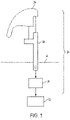
FIG. 1 is a schematic of a gear shift control system as one, non-limiting, exemplary embodiment of the present disclosure; -
FIG. 2 is a cross section of a gear shift module of the gear shift control system; -
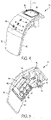
FIG. 3 is an under perspective view of the gear shift module; -
FIG. 4 is an outer perspective view of the gear shift module; -
FIG. 5 is an under perspective view of an undercover of the gear shift module; -
FIG. 6 is an under perspective view of a push button of the gear shift module; -
FIG. 7 is an outer perspective view of a cover of the gear shift module; -
FIG. 8 is a perspective view of a lever of the gear shift module; -
FIG. 9 is a perspective view of a light guide of the gear shift module; -
FIG. 10 is an under perspective view of a printed circuit board of the gear shift module; -
FIG. 11 is a partial cross section of the gear shift module illustrating the push button of the actuator assembly; -
FIG. 12 is an enlarged cross section of the actuator assembly illustrating a distal end portion of the push button; -
FIG. 13 is a cross section of an electric switch of the printed circuit board; and -
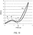
FIG. 14 is a graph illustrating force verse axial displacement of the button. - Referring to
FIG. 1 , a gearshift control system 20 as one, non-limiting, embodiment of the present disclosure is illustrated and connected to atransmission 22 of a vehicle powertrain. The gearshift control system 20 may include agear shift module 24, a lever or substructure 26 (i.e., armature), and acontrol device 28. In one embodiment, thegear shift module 24 may be a preassembled, modular, component of the gearshift control system 20. Thegear shift module 24 is supported by, and fixed to, thelever 26, or a knob of the lever. Thelever 26 may extend from thecontrol device 28, through aninterior console 30 of a vehicle, and to thegear shift module 24. In one embodiment, thelever 26 may be supported by, and/or generally pivotally connected to, thecontrol device 28. Thecontrol device 28 is adapted to associate a position of thelever 26 to a desired transmission position and/or function (i.e., park, neutral, reverse, forward, etc.). In one embodiment, thecontrol device 28 may be adapted to mechanically place thetransmission 22 in the desired shift position. In another embodiment, thecontrol device 28 may be part of a shift-by-wire system. It is further contemplated and understood that thegear shift module 24 may be fixed to the knob of the lever, and/or may be a portion of the knob attachable or integrated to thelever 26. - Referring to
FIGS. 2-4 , thegear shift module 24 functions as a user interface between a vehicle operator and thetransmission 22. Thegear shift module 24 includes acover assembly 32, anactuator assembly 34, a circuit board 36 (e.g., printed circuit board, PCB), and alight guide 38. Thecover assembly 32 includes an undercover 40 (also seeFIG. 5 ), and a cover 42 (also seeFIG. 7 ). The undercover 40 generally functions as a substructure and may be substantially hidden from the view of the vehicle operator. Thecover 42 covers, is connected to, and is supported by, the undercover 40. As best shown inFIGS. 4 and7 , thecover 42 may include various visual features (44, 46, 48) that may be continuously or selectively illuminated.Feature 44 may be an "R" signifying the transmission in reverse,feature 46 may be an "N" signifying the transmission in neutral, andfeature 48 may be a "D" signifying the transmission in drive. Yet further, anothervisual feature 49 may include the figure "M" signifying the ability to shift transmission gears one-by-one. It is contemplated and understood that the undercover 40 and thecover 42 may be manufactured as two separate, attachable, pieces, or may be manufactured as a single piece in, for example, a plastic single injection or bi-injection manufacturing process (i.e., molded). - Referring to
FIG. 5 , the undercover 40 of thecover assembly 32 may include a first side 50 (e.g., external or top side) and an opposite side 52 (e.g., under side).First side 50 substantially faces, and may be in contact with, thecover 42. The undercover 40 may further include a plurality of openings (i.e., three identified as 53, 54, 56) defined by a plurality ofrespective conduits side 52. Eachconduit respective features cover 42. In one embodiment, theconduits - Referring to
FIGS. 2, 3 , and10 , thecircuit board 36 may be attached (e.g., snap fitted, adhered, or otherwise fastened) to the undercover 40 of thecover assembly 32. Thecircuit board 36 includes aface 64, an opposite face 66 (i.e., faces in an opposite direction from face 64), at least one electrical switch (i.e., two illustrated as 68, 70 for operational redundancy), and a multitude of light sources (i.e., four illustrated as 72, 74, 76, 78) that may, for example, be Light Emitting Diodes (LEDs). Thelight sources face 64, and thelight source 78 and theswitches opposite face 66. In another example, alllight sources face 64, but thelight sources light source 78 may emit light in a different direction. - When the
gear shift module 24 is fully assembled, thelight sources respective openings respective conduits conduits face 64 of thecircuit board 36. Theswitches actuator assembly 34, and thelight source 78 is positioned to output light rays into thelight guide 38. - Referring to
FIGS. 2 and4 , theactuator assembly 34 is adapted to be actuated by the operator of the vehicle. Once actuated, the operator may then change transmission positions by, for example, grasping thegear shift module 24 and moving or pivoting thelever 26 of the gearshift control system 20, or may directly change transmission positions from one to another position, or to a specific position (e.g., drive "D" to park "P". Theactuator assembly 34 may include a button 80 (e.g., push button, also seeFIG. 6 )), and a linkage 82 (also seeFIG. 8 ). Thebutton 80 may include apad 84, at least one elongated guide 86 (i.e., three illustrated), and at least one stanchion 88 (i.e., two illustrated). Thepad 84 may be located in an opening 90 (seeFIG. 7 ) defined by boundaries of thecover 42, and may include anexternal surface 92 exposed through thecover 42, and aninternal surface 94 orientated opposite to theexternal surface 92. It is contemplated and understood that thebutton 80 may be any button configured to perform any variety of functions (i.e., a function button). In the embodiment illustrated, thebutton 80 is a shift button. Thebutton 80 may be a single piece, and may be made of plastic (e.g., injection molded plastic). Similarly, thelinkage 82 may be a single, unitary, piece, and may be made of plastic (e.g., injection molded plastic). - The
function button 80 may function to place the vehicle in park (i.e., "P" position), or may function to release or enable shifting of the transmission. In yet another embodiment, thegear shift module 24 may include both a park button and a shift button that may generally operate off of asingle circuit board 36. - In operation, the
function button 80 is adapted to be depress by the operator of the vehicle to perform the function. For example, thefunction button 80 may be a park button and is depressed to enable placing the vehicle from drive "D" to park "P". Actuation of thebutton 80 moves along a substantially linear centerline C (seeFIGS. 4 ,6 and11 ), and between an un-pressed position and a pressed position. Thestanchions 88 of thebutton 80 project longitudinally outward from theinternal surface 94, through the undercover 40, and are substantially parallel to the centerline C. Similarly, theguides 86 project longitudinally outward from theinternal surface 94, through the undercover 40, and are substantially parallel to the centerline C. - The
guides 86 of thebutton 80 are received inrespective channels 96 that may be defined by boundaries carried byrespective legs 98 of the undercover 40, which project outward from the side 52 (i.e., underside) of the undercover 40 (seeFIG. 5 ). In this way, the undercover 40 provides smooth, linear, actuation of thebutton 80 between the pressed and depressed positions. - Referring to
FIGS. 8 ,11 and 12 , thelinkage 82 of theactuator assembly 34 is generally constructed to link thebutton 80 with theelectrical switches button 80 is moved along the centerline C, the button bears upon thelinkage 82, causing thelinkage 82 to actuate theswitches linkage 82 may be a pivotal linkage, and may include anend portion 100, anend portion 102 orientatedopposite end portion 100, and a mid-portion 104 generally located between theend portions end portion 100 is in contact with adistal end portion 106 of thestanchions 88 of thebutton 80, and theend portion 102 is in contact with theswitches -
Distal end portion 106 of the eachstanchion 88 may include a resilientlyflexible member 110 for taking-up slack in the actuator assembly 34 (alleviating any lost motion), and anindex 108 that is generally less resilient than theflexible member 110 and is opposed to endportion 100. At least a portion of the resilientlyflexible member 110 is spaced axially in front of theindex 108 and with respect to the centerline C, and is in direct, biased, contact with theend portion 100 of thelinkage 82. - In operation of the
actuator assembly 34, and when thebutton 80 is in the un-pressed position, a biasing member 112 (e.g., coiled spring, seeFIG. 13 ) of eachelectrical switch arrow 114 inFIG. 13 ) that is transmitted through thelinkage 82 and against the resilientlyflexible member 110 of thepush button 80, thereby biasing thepush button 80 in, or toward, the un-pressed position. When the operator of the vehicle depresses thebutton 80, a force (seearrow 116 inFIG. 12 ) is applied to thepad 84 of thebutton 80 that exceeds the reactive force of the biasingmember 112 of theswitches flexible member 110 may be displaced axially by a pre-determined distance that may be less than, or equal to, the axial spacing between theindex 108 and themember 110. That is, in order to remove free-play, this flexible geometry is interference fitted against thelinkage 82 during assembly. The compression effort is low enough to reduce the free play without modifying the initial peak effort of theswitches flexible member 110 is lower than the force exerted by theswitches button 80 is being pressed. - Referring to
FIG. 14 a graph depicts the dynamics of theactuator assembly 34 having an X-axis depicting axial displacement along centerline C, and a Y-axis depicting the appliedforce 116.Point 130 is associated with the maximum effort to generally activate thebutton 80 at about 3.2 N as one example.Point 132 is associated with the return effort (i.e., force 114 from the switch) at about greater than 0.3 N as one example.Point 134 is associated with the swallowing effort at about 1.8 N as one example.Point 136 is associated with the axial stroke along centerline C to activate thebutton 80 at about 1.4 mm as one example.Point 138 is the stroke of thebutton 80 under about 10 N and about 2mm as one example.Point 140 is the maximum stroke under 2 N and about 0.4 mm as one example. - Referring to
FIGS. 2 and9 , thelight guide 38 is adapted to receive light rays from thelight source 78 at aninlet face 118, transmit the light internally, and expel the light rays at anoutlet face 120 that generally opposes thepad 84 of thebutton 80. In one embodiment, thelight guide 38 may be supported by, or fixed to, the undercover 40. At least a portion of thepad 84 may be at least partially translucent to permit the illumination of the pad via the light rays outputted by thelight guide 38. An imaginary plane of theinlet face 118 may traverse an imaginary plane of theoutlet face 120. At least one side of thelight guide 38 may include a reflector 122 (i.e., reflective surface, coating, etc.) to optimize the transmission of the light rays between the faces. - In one embodiment, the
pad 84 of thebutton 80 may be continuously illuminated. In another embodiment, thelight source 78 may energize upon, or in relation with, the actuation of theswitches - Benefits and advantages of the present disclosure include an integrated cover and undercover with an actuator assembly, PCB, and light guide all as one modular assembly. Other advantages include improvements in illumination alignment, transmission efficiency, and a reduction in actuator assembly free play. Further advantage includes cost reductions attributable, in-part, via the use of a single PCB and a reduction in wiring, tolerance stack up simplification establishing better constant gap between the button and the cover, and simplification in assembly. The present disclosure is thus not limited to the particular examples disclosed herein, but includes all embodiments falling within the scope of the appended claims.
Claims (11)
- A preassembled gear shift module (24) adapted to connect to a substructure (26), the preassembled gear shift module (24) comprising:- a cover assembly (32) including a cover (42) and an undercover (40) attachable to the cover (32);- a circuit board (36) attached to the undercover (40) of the cover assembly (32), the circuit board (36) including a first face (64) and an opposite second face (66), and further including:- a switch (68,70);- a first light source (78) and a second light source (72, 74, 76) adapted to project light through the cover assembly (32) to illuminate an external visual feature (44, 46, 48) on the cover assembly (32);- a function button (80) exposed through the cover assembly (32), the function button (80) being operably connected to the switch (68, 70); and- a light guide (38) supported by the undercover (40) and adapted to channel light from the first light source (78) of the circuit board (36) and through the function button (80); characterized in that the switch (68, 70) is mounted on the first face (64) of the circuit board (36), and the second light source (72, 74, 76) is mounted on the second face (66) of the circuit board (36).
- The preassembled gear shift module (24) set forth in claim 1, wherein the first light source (78) and the switch (68, 70) are mounted on the first face (64) of the circuit board (36), and the second light source (72, 74, 76) is mounted on the second face (66) of the circuit board (36).
- The preassembled gear shift module (24) set forth in claim 1 or 2, further comprising: a linkage (82) pivotally connected to the cover assembly (32), and extending between and in contact with the function button (80) and the switch (68, 70).
- The preassembled gear shift module (24) set forth in any of the preceding claims, wherein the function button (80) is adapted to move linearly between an un-pressed position and a pressed position.
- The preassembled gear shift module (24) set forth in claim 3 or 4, wherein the switch (68, 70) includes a biasing member (112) adapted to transmit a force through the linkage (82) and upon the function button (80) to bias the function button (80) toward the un-pressed position.
- The preassembled gear shift module (24) set forth in any of the preceding claims, wherein the cover assembly (32) defines an opening (90) for receipt and exposure of the function button (80).
- The preassembled gear shift module (24) set forth in any of the preceding claims, wherein the button (80) includes a pad (84), at least one elongated guide (86) and at least one stanchion (88), the stanchion (88) including a resiliently flexible member (110) for taking-up slack in the actuator assembly (34).
- The preassembled gear shift module (24) set forth in any of the preceding claims, wherein the light guide (38) includes a reflector (122) to optimize transmission of light rays between the faces (64, 66) of the circuit board (36).
- A shift lever comprising the preassembled gear shift module (24) set forth in any of the preceding claims.
- The shift lever set forth in claim 9, wherein a force needed to fully flex the resiliently flexible member (110) is lower than the force exerted by the switch (68, 70).
- The shift lever set forth in claim 9 or 10, further comprising:a second stanchion in contact with the linkage; anda second switch in contact with the linkage.
Applications Claiming Priority (1)
| Application Number | Priority Date | Filing Date | Title |
|---|---|---|---|
| US15/959,784 US10982754B2 (en) | 2018-04-23 | 2018-04-23 | Vehicle gear shift module |
Publications (2)
| Publication Number | Publication Date |
|---|---|
| EP3561835A1 EP3561835A1 (en) | 2019-10-30 |
| EP3561835B1 true EP3561835B1 (en) | 2022-06-08 |
Family
ID=66251591
Family Applications (1)
| Application Number | Title | Priority Date | Filing Date |
|---|---|---|---|
| EP19170679.5A Active EP3561835B1 (en) | 2018-04-23 | 2019-04-23 | Vehicle gear shift module |
Country Status (3)
| Country | Link |
|---|---|
| US (1) | US10982754B2 (en) |
| EP (1) | EP3561835B1 (en) |
| CN (1) | CN110388457B (en) |
Families Citing this family (6)
| Publication number | Priority date | Publication date | Assignee | Title |
|---|---|---|---|---|
| US10982754B2 (en) * | 2018-04-23 | 2021-04-20 | Ficosa International (Taicang) Co. Ltd. | Vehicle gear shift module |
| KR102598959B1 (en) * | 2018-11-14 | 2023-11-06 | 현대자동차주식회사 | Shift by wire type shifting control apparatus for a vehicle |
| CN110953332B (en) * | 2019-12-10 | 2022-08-02 | 宁波吉利汽车研究开发有限公司 | Electronic gear shifter, gear shifting control method and vehicle |
| CN110905999A (en) * | 2019-12-20 | 2020-03-24 | 张永祥 | Bulb and gearshift connection structure |
| KR102214410B1 (en) * | 2020-12-04 | 2021-02-08 | 방재용 | Gear knob for vehicles |
| CN113090745B (en) * | 2021-04-02 | 2022-09-06 | 宁波高发汽车控制系统股份有限公司 | Multifunctional rotary gear shifter |
Family Cites Families (31)
| Publication number | Priority date | Publication date | Assignee | Title |
|---|---|---|---|---|
| IT1179630B (en) * | 1984-05-02 | 1987-09-16 | Fiat Auto Spa | CONTROL LEVER FOR A COMMAND DEVICE FOR SIGNALING DEVICES AND VEHICLE OPERATORS |
| FR2607316A1 (en) * | 1986-11-25 | 1988-05-27 | Telemecanique Electrique | CONTROL BOX, IN PARTICULAR THE TYPE SUSPENDED ON A CABLE FOR THE CONTROL OF ELECTRIC MOTORS WITH TWO SENSES OF MARKET |
| US5854458A (en) * | 1997-03-03 | 1998-12-29 | Methode Electronics, Inc. | Stalk mounted three function switch assembly having a single multiplexed output |
| JP3765550B2 (en) * | 1997-03-21 | 2006-04-12 | アルプス電気株式会社 | In-vehicle knob switch device |
| US6145401A (en) * | 1997-11-21 | 2000-11-14 | Caterpillar Inc. | Modular control handle |
| DE19936265B4 (en) * | 1999-07-31 | 2005-10-06 | Deere & Company, Moline | Sensor with control device and control handle for vehicle control |
| DE10025357B4 (en) | 2000-05-23 | 2006-02-16 | Lisa Dräxlmaier GmbH | Gear shift lever of modular design with shift module |
| DE10131219C1 (en) * | 2001-06-28 | 2003-03-06 | Itt Mfg Enterprises Inc | Switch grip for earthworking or agricultural machine has soft elastic mat covering each switch unit incorporated in hard plastics housing of grip part |
| US6834987B2 (en) * | 2002-11-15 | 2004-12-28 | Dennis R. Zynda | Illuminated medallion for transmission shifter knobs |
| KR20050017889A (en) * | 2003-08-11 | 2005-02-23 | 현대자동차주식회사 | Multi function transmission gear shift lever of vehicle |
| US20050262819A1 (en) * | 2004-06-01 | 2005-12-01 | Weber Steve J | Lawnmower control assembly |
| US7250578B2 (en) * | 2004-12-29 | 2007-07-31 | Dura Global Technologies, Inc. | Multifunction switching arrangement for controlling transmission overdrive and autostick functions |
| JP2007084033A (en) | 2005-08-25 | 2007-04-05 | Tsuda Industries Co Ltd | Shift lever device |
| JP2007080788A (en) * | 2005-09-16 | 2007-03-29 | Alps Electric Co Ltd | On-board knob switching device |
| KR100628626B1 (en) * | 2005-09-22 | 2006-09-26 | 쌍용자동차 주식회사 | Knob linkage structure of manual shift lever |
| CH698138B1 (en) * | 2005-11-09 | 2009-05-29 | Abatek Internat Ag | Integrated switch respectively integrated button. |
| US7913583B2 (en) * | 2006-06-28 | 2011-03-29 | Nexteer (Beijing) Technology Co., Ltd. | Transmission shift control mechanism and method of installation |
| KR100780845B1 (en) * | 2006-09-05 | 2007-11-30 | 주식회사제로하이텍 | Knob switch for automatic vehicle and shift lever equipped with it |
| JP2008192559A (en) * | 2007-02-07 | 2008-08-21 | Alps Electric Co Ltd | On-vehicle knob switch |
| WO2010039845A2 (en) * | 2008-09-30 | 2010-04-08 | Dura Global Technologies, Inc. | Shifter assembly including display and actuation for driver control |
| JP5385866B2 (en) * | 2010-06-30 | 2014-01-08 | 富士機工株式会社 | Shift knob mounting structure for vehicle shift lever device |
| CN103619632B (en) * | 2011-06-28 | 2016-05-11 | 本田技研工业株式会社 | Speed change gear and manufacture method thereof |
| JP5789539B2 (en) * | 2012-02-15 | 2015-10-07 | バイエリッシェ モートーレン ウエルケ アクチエンゲゼルシャフトBayerische Motoren Werke Aktiengesellschaft | In-vehicle lever switch device |
| CN104271992B (en) | 2012-05-03 | 2016-03-23 | 康斯博格汽车股份公司 | There is shifter assembly and the correlation method of the device for guard shield being couple to gear level |
| KR20140031022A (en) * | 2012-09-04 | 2014-03-12 | 현대모비스 주식회사 | Shift lever for vehicle |
| CN203325771U (en) * | 2013-07-08 | 2013-12-04 | 浙江泰康电子有限公司 | Steering wheel switch |
| CN203401968U (en) * | 2013-07-30 | 2014-01-22 | 马夸特开关(上海)有限公司 | Electronic gear lever with side-direction unlocking button |
| CN203617186U (en) * | 2013-12-20 | 2014-05-28 | 黄山奥特斯电气有限公司 | Electronic parking brake switch for automobiles |
| US9726275B2 (en) * | 2014-12-18 | 2017-08-08 | Sl Corporation | Shift lever of automotive transmission |
| KR102711731B1 (en) * | 2016-10-06 | 2024-09-27 | 엘에스오토모티브테크놀로지스 주식회사 | Gear shift paddle switch |
| US10982754B2 (en) * | 2018-04-23 | 2021-04-20 | Ficosa International (Taicang) Co. Ltd. | Vehicle gear shift module |
-
2018
- 2018-04-23 US US15/959,784 patent/US10982754B2/en active Active
- 2018-12-26 CN CN201811600057.XA patent/CN110388457B/en active Active
-
2019
- 2019-04-23 EP EP19170679.5A patent/EP3561835B1/en active Active
Also Published As
| Publication number | Publication date |
|---|---|
| CN110388457A (en) | 2019-10-29 |
| US10982754B2 (en) | 2021-04-20 |
| CN110388457B (en) | 2022-06-03 |
| EP3561835A1 (en) | 2019-10-30 |
| US20190323599A1 (en) | 2019-10-24 |
Similar Documents
| Publication | Publication Date | Title |
|---|---|---|
| US10982754B2 (en) | Vehicle gear shift module | |
| US6768067B2 (en) | Switch device in steering wheel and steering wheel | |
| US8485061B2 (en) | Operating device with selector lever return | |
| DE69806680D1 (en) | Gear lever knob for a manual transmission with a user interface | |
| CN112793506B (en) | Knob formula gear shifting equipment's ambient light device | |
| US4986399A (en) | Shifter brake interlock system | |
| KR101542640B1 (en) | Operating device having a bundle of light guides | |
| CN112797149B (en) | Knob type gear shifting control equipment of electronic gear shifting system | |
| KR101704253B1 (en) | Button type electronic shift lever system | |
| KR101937030B1 (en) | Electronic shifting apparatus | |
| KR20090115068A (en) | Manipulators on the vehicle steering wheel | |
| US6569058B2 (en) | Linear motion shifter | |
| JPH1016594A (en) | Automatic shifting operation device | |
| EP0718527A3 (en) | Shift control device for a vehicle with an automatic transmission | |
| EP1846264A2 (en) | Led molded light guide | |
| KR20170074238A (en) | Switching apparatus for a control system for a vehicle, and control system for a vehicle | |
| US20080264193A1 (en) | Shifting Device for a Transmission of a Motor Vehicle and Shifting Method | |
| JP2008540239A (en) | Shift device and shift method for automobile transmission | |
| US7004059B2 (en) | Hydraulic master cylinder switch | |
| KR20100070781A (en) | Lighting device for controller symbol of air conditioning system in automotive vehicles | |
| KR20050098518A (en) | Shifting apparatus of manual transmission | |
| JP3163444U (en) | Manual switch | |
| KR970000860B1 (en) | Reverse operating error prevention device for motor car manual transmission | |
| KR19980061197A (en) | Selecting Structure of Automotive Transmission | |
| JPS61246819A (en) | Structure of change gear operating lever for vehicle |
Legal Events
| Date | Code | Title | Description |
|---|---|---|---|
| PUAI | Public reference made under article 153(3) epc to a published international application that has entered the european phase |
Free format text: ORIGINAL CODE: 0009012 |
|
| STAA | Information on the status of an ep patent application or granted ep patent |
Free format text: STATUS: THE APPLICATION HAS BEEN PUBLISHED |
|
| AK | Designated contracting states |
Kind code of ref document: A1 Designated state(s): AL AT BE BG CH CY CZ DE DK EE ES FI FR GB GR HR HU IE IS IT LI LT LU LV MC MK MT NL NO PL PT RO RS SE SI SK SM TR |
|
| AX | Request for extension of the european patent |
Extension state: BA ME |
|
| STAA | Information on the status of an ep patent application or granted ep patent |
Free format text: STATUS: REQUEST FOR EXAMINATION WAS MADE |
|
| 17P | Request for examination filed |
Effective date: 20200430 |
|
| RBV | Designated contracting states (corrected) |
Designated state(s): AL AT BE BG CH CY CZ DE DK EE ES FI FR GB GR HR HU IE IS IT LI LT LU LV MC MK MT NL NO PL PT RO RS SE SI SK SM TR |
|
| GRAP | Despatch of communication of intention to grant a patent |
Free format text: ORIGINAL CODE: EPIDOSNIGR1 |
|
| STAA | Information on the status of an ep patent application or granted ep patent |
Free format text: STATUS: GRANT OF PATENT IS INTENDED |
|
| INTG | Intention to grant announced |
Effective date: 20211214 |
|
| GRAS | Grant fee paid |
Free format text: ORIGINAL CODE: EPIDOSNIGR3 |
|
| GRAA | (expected) grant |
Free format text: ORIGINAL CODE: 0009210 |
|
| STAA | Information on the status of an ep patent application or granted ep patent |
Free format text: STATUS: THE PATENT HAS BEEN GRANTED |
|
| AK | Designated contracting states |
Kind code of ref document: B1 Designated state(s): AL AT BE BG CH CY CZ DE DK EE ES FI FR GB GR HR HU IE IS IT LI LT LU LV MC MK MT NL NO PL PT RO RS SE SI SK SM TR |
|
| REG | Reference to a national code |
Ref country code: AT Ref legal event code: REF Ref document number: 1497502 Country of ref document: AT Kind code of ref document: T Effective date: 20220615 Ref country code: CH Ref legal event code: EP |
|
| REG | Reference to a national code |
Ref country code: DE Ref legal event code: R096 Ref document number: 602019015581 Country of ref document: DE |
|
| REG | Reference to a national code |
Ref country code: IE Ref legal event code: FG4D |
|
| REG | Reference to a national code |
Ref country code: LT Ref legal event code: MG9D |
|
| REG | Reference to a national code |
Ref country code: NL Ref legal event code: MP Effective date: 20220608 |
|
| PG25 | Lapsed in a contracting state [announced via postgrant information from national office to epo] |
Ref country code: SE Free format text: LAPSE BECAUSE OF FAILURE TO SUBMIT A TRANSLATION OF THE DESCRIPTION OR TO PAY THE FEE WITHIN THE PRESCRIBED TIME-LIMIT Effective date: 20220608 Ref country code: NO Free format text: LAPSE BECAUSE OF FAILURE TO SUBMIT A TRANSLATION OF THE DESCRIPTION OR TO PAY THE FEE WITHIN THE PRESCRIBED TIME-LIMIT Effective date: 20220908 Ref country code: LT Free format text: LAPSE BECAUSE OF FAILURE TO SUBMIT A TRANSLATION OF THE DESCRIPTION OR TO PAY THE FEE WITHIN THE PRESCRIBED TIME-LIMIT Effective date: 20220608 Ref country code: HR Free format text: LAPSE BECAUSE OF FAILURE TO SUBMIT A TRANSLATION OF THE DESCRIPTION OR TO PAY THE FEE WITHIN THE PRESCRIBED TIME-LIMIT Effective date: 20220608 Ref country code: GR Free format text: LAPSE BECAUSE OF FAILURE TO SUBMIT A TRANSLATION OF THE DESCRIPTION OR TO PAY THE FEE WITHIN THE PRESCRIBED TIME-LIMIT Effective date: 20220909 Ref country code: FI Free format text: LAPSE BECAUSE OF FAILURE TO SUBMIT A TRANSLATION OF THE DESCRIPTION OR TO PAY THE FEE WITHIN THE PRESCRIBED TIME-LIMIT Effective date: 20220608 Ref country code: ES Free format text: LAPSE BECAUSE OF FAILURE TO SUBMIT A TRANSLATION OF THE DESCRIPTION OR TO PAY THE FEE WITHIN THE PRESCRIBED TIME-LIMIT Effective date: 20220608 Ref country code: BG Free format text: LAPSE BECAUSE OF FAILURE TO SUBMIT A TRANSLATION OF THE DESCRIPTION OR TO PAY THE FEE WITHIN THE PRESCRIBED TIME-LIMIT Effective date: 20220908 |
|
| REG | Reference to a national code |
Ref country code: AT Ref legal event code: MK05 Ref document number: 1497502 Country of ref document: AT Kind code of ref document: T Effective date: 20220608 |
|
| PG25 | Lapsed in a contracting state [announced via postgrant information from national office to epo] |
Ref country code: RS Free format text: LAPSE BECAUSE OF FAILURE TO SUBMIT A TRANSLATION OF THE DESCRIPTION OR TO PAY THE FEE WITHIN THE PRESCRIBED TIME-LIMIT Effective date: 20220608 Ref country code: LV Free format text: LAPSE BECAUSE OF FAILURE TO SUBMIT A TRANSLATION OF THE DESCRIPTION OR TO PAY THE FEE WITHIN THE PRESCRIBED TIME-LIMIT Effective date: 20220608 |
|
| PG25 | Lapsed in a contracting state [announced via postgrant information from national office to epo] |
Ref country code: NL Free format text: LAPSE BECAUSE OF FAILURE TO SUBMIT A TRANSLATION OF THE DESCRIPTION OR TO PAY THE FEE WITHIN THE PRESCRIBED TIME-LIMIT Effective date: 20220608 |
|
| PG25 | Lapsed in a contracting state [announced via postgrant information from national office to epo] |
Ref country code: SM Free format text: LAPSE BECAUSE OF FAILURE TO SUBMIT A TRANSLATION OF THE DESCRIPTION OR TO PAY THE FEE WITHIN THE PRESCRIBED TIME-LIMIT Effective date: 20220608 Ref country code: SK Free format text: LAPSE BECAUSE OF FAILURE TO SUBMIT A TRANSLATION OF THE DESCRIPTION OR TO PAY THE FEE WITHIN THE PRESCRIBED TIME-LIMIT Effective date: 20220608 Ref country code: RO Free format text: LAPSE BECAUSE OF FAILURE TO SUBMIT A TRANSLATION OF THE DESCRIPTION OR TO PAY THE FEE WITHIN THE PRESCRIBED TIME-LIMIT Effective date: 20220608 Ref country code: PT Free format text: LAPSE BECAUSE OF FAILURE TO SUBMIT A TRANSLATION OF THE DESCRIPTION OR TO PAY THE FEE WITHIN THE PRESCRIBED TIME-LIMIT Effective date: 20221010 Ref country code: EE Free format text: LAPSE BECAUSE OF FAILURE TO SUBMIT A TRANSLATION OF THE DESCRIPTION OR TO PAY THE FEE WITHIN THE PRESCRIBED TIME-LIMIT Effective date: 20220608 Ref country code: CZ Free format text: LAPSE BECAUSE OF FAILURE TO SUBMIT A TRANSLATION OF THE DESCRIPTION OR TO PAY THE FEE WITHIN THE PRESCRIBED TIME-LIMIT Effective date: 20220608 Ref country code: AT Free format text: LAPSE BECAUSE OF FAILURE TO SUBMIT A TRANSLATION OF THE DESCRIPTION OR TO PAY THE FEE WITHIN THE PRESCRIBED TIME-LIMIT Effective date: 20220608 |
|
| PG25 | Lapsed in a contracting state [announced via postgrant information from national office to epo] |
Ref country code: PL Free format text: LAPSE BECAUSE OF FAILURE TO SUBMIT A TRANSLATION OF THE DESCRIPTION OR TO PAY THE FEE WITHIN THE PRESCRIBED TIME-LIMIT Effective date: 20220608 Ref country code: IS Free format text: LAPSE BECAUSE OF FAILURE TO SUBMIT A TRANSLATION OF THE DESCRIPTION OR TO PAY THE FEE WITHIN THE PRESCRIBED TIME-LIMIT Effective date: 20221008 |
|
| REG | Reference to a national code |
Ref country code: DE Ref legal event code: R097 Ref document number: 602019015581 Country of ref document: DE |
|
| PG25 | Lapsed in a contracting state [announced via postgrant information from national office to epo] |
Ref country code: AL Free format text: LAPSE BECAUSE OF FAILURE TO SUBMIT A TRANSLATION OF THE DESCRIPTION OR TO PAY THE FEE WITHIN THE PRESCRIBED TIME-LIMIT Effective date: 20220608 |
|
| PLBE | No opposition filed within time limit |
Free format text: ORIGINAL CODE: 0009261 |
|
| STAA | Information on the status of an ep patent application or granted ep patent |
Free format text: STATUS: NO OPPOSITION FILED WITHIN TIME LIMIT |
|
| PG25 | Lapsed in a contracting state [announced via postgrant information from national office to epo] |
Ref country code: DK Free format text: LAPSE BECAUSE OF FAILURE TO SUBMIT A TRANSLATION OF THE DESCRIPTION OR TO PAY THE FEE WITHIN THE PRESCRIBED TIME-LIMIT Effective date: 20220608 |
|
| 26N | No opposition filed |
Effective date: 20230310 |
|
| PG25 | Lapsed in a contracting state [announced via postgrant information from national office to epo] |
Ref country code: SI Free format text: LAPSE BECAUSE OF FAILURE TO SUBMIT A TRANSLATION OF THE DESCRIPTION OR TO PAY THE FEE WITHIN THE PRESCRIBED TIME-LIMIT Effective date: 20220608 |
|
| REG | Reference to a national code |
Ref country code: CH Ref legal event code: PL |
|
| GBPC | Gb: european patent ceased through non-payment of renewal fee |
Effective date: 20230423 |
|
| PG25 | Lapsed in a contracting state [announced via postgrant information from national office to epo] |
Ref country code: LU Free format text: LAPSE BECAUSE OF NON-PAYMENT OF DUE FEES Effective date: 20230423 |
|
| REG | Reference to a national code |
Ref country code: BE Ref legal event code: MM Effective date: 20230430 |
|
| PG25 | Lapsed in a contracting state [announced via postgrant information from national office to epo] |
Ref country code: MC Free format text: LAPSE BECAUSE OF FAILURE TO SUBMIT A TRANSLATION OF THE DESCRIPTION OR TO PAY THE FEE WITHIN THE PRESCRIBED TIME-LIMIT Effective date: 20220608 |
|
| PG25 | Lapsed in a contracting state [announced via postgrant information from national office to epo] |
Ref country code: GB Free format text: LAPSE BECAUSE OF NON-PAYMENT OF DUE FEES Effective date: 20230423 |
|
| PG25 | Lapsed in a contracting state [announced via postgrant information from national office to epo] |
Ref country code: MC Free format text: LAPSE BECAUSE OF FAILURE TO SUBMIT A TRANSLATION OF THE DESCRIPTION OR TO PAY THE FEE WITHIN THE PRESCRIBED TIME-LIMIT Effective date: 20220608 Ref country code: LI Free format text: LAPSE BECAUSE OF NON-PAYMENT OF DUE FEES Effective date: 20230430 Ref country code: IT Free format text: LAPSE BECAUSE OF FAILURE TO SUBMIT A TRANSLATION OF THE DESCRIPTION OR TO PAY THE FEE WITHIN THE PRESCRIBED TIME-LIMIT Effective date: 20220608 Ref country code: GB Free format text: LAPSE BECAUSE OF NON-PAYMENT OF DUE FEES Effective date: 20230423 Ref country code: FR Free format text: LAPSE BECAUSE OF NON-PAYMENT OF DUE FEES Effective date: 20230430 Ref country code: CH Free format text: LAPSE BECAUSE OF NON-PAYMENT OF DUE FEES Effective date: 20230430 |
|
| REG | Reference to a national code |
Ref country code: IE Ref legal event code: MM4A |
|
| PG25 | Lapsed in a contracting state [announced via postgrant information from national office to epo] |
Ref country code: BE Free format text: LAPSE BECAUSE OF NON-PAYMENT OF DUE FEES Effective date: 20230430 |
|
| PG25 | Lapsed in a contracting state [announced via postgrant information from national office to epo] |
Ref country code: IE Free format text: LAPSE BECAUSE OF NON-PAYMENT OF DUE FEES Effective date: 20230423 |
|
| PG25 | Lapsed in a contracting state [announced via postgrant information from national office to epo] |
Ref country code: IE Free format text: LAPSE BECAUSE OF NON-PAYMENT OF DUE FEES Effective date: 20230423 |
|
| PG25 | Lapsed in a contracting state [announced via postgrant information from national office to epo] |
Ref country code: BG Free format text: LAPSE BECAUSE OF FAILURE TO SUBMIT A TRANSLATION OF THE DESCRIPTION OR TO PAY THE FEE WITHIN THE PRESCRIBED TIME-LIMIT Effective date: 20220608 |
|
| PG25 | Lapsed in a contracting state [announced via postgrant information from national office to epo] |
Ref country code: BG Free format text: LAPSE BECAUSE OF FAILURE TO SUBMIT A TRANSLATION OF THE DESCRIPTION OR TO PAY THE FEE WITHIN THE PRESCRIBED TIME-LIMIT Effective date: 20220608 |
|
| PGFP | Annual fee paid to national office [announced via postgrant information from national office to epo] |
Ref country code: DE Payment date: 20250429 Year of fee payment: 7 |
|
| PG25 | Lapsed in a contracting state [announced via postgrant information from national office to epo] |
Ref country code: CY Free format text: LAPSE BECAUSE OF FAILURE TO SUBMIT A TRANSLATION OF THE DESCRIPTION OR TO PAY THE FEE WITHIN THE PRESCRIBED TIME-LIMIT; INVALID AB INITIO Effective date: 20190423 |
|
| PG25 | Lapsed in a contracting state [announced via postgrant information from national office to epo] |
Ref country code: HU Free format text: LAPSE BECAUSE OF FAILURE TO SUBMIT A TRANSLATION OF THE DESCRIPTION OR TO PAY THE FEE WITHIN THE PRESCRIBED TIME-LIMIT; INVALID AB INITIO Effective date: 20190423 |
|
| PG25 | Lapsed in a contracting state [announced via postgrant information from national office to epo] |
Ref country code: TR Free format text: LAPSE BECAUSE OF FAILURE TO SUBMIT A TRANSLATION OF THE DESCRIPTION OR TO PAY THE FEE WITHIN THE PRESCRIBED TIME-LIMIT Effective date: 20220608 |