EP3561594B1 - Illumination system, projection device and operating method thereof - Google Patents
Illumination system, projection device and operating method thereof Download PDFInfo
- Publication number
- EP3561594B1 EP3561594B1 EP19171345.2A EP19171345A EP3561594B1 EP 3561594 B1 EP3561594 B1 EP 3561594B1 EP 19171345 A EP19171345 A EP 19171345A EP 3561594 B1 EP3561594 B1 EP 3561594B1
- Authority
- EP
- European Patent Office
- Prior art keywords
- light source
- blue light
- excitation
- excited
- dichroic element
- Prior art date
- Legal status (The legal status is an assumption and is not a legal conclusion. Google has not performed a legal analysis and makes no representation as to the accuracy of the status listed.)
- Active
Links
- 238000005286 illumination Methods 0.000 title claims description 156
- 238000011017 operating method Methods 0.000 title claims description 16
- 230000005284 excitation Effects 0.000 claims description 199
- 230000003287 optical effect Effects 0.000 claims description 66
- 239000000463 material Substances 0.000 claims description 41
- 238000009792 diffusion process Methods 0.000 claims description 23
- 238000000034 method Methods 0.000 description 17
- OAICVXFJPJFONN-UHFFFAOYSA-N Phosphorus Chemical compound [P] OAICVXFJPJFONN-UHFFFAOYSA-N 0.000 description 10
- 230000003213 activating effect Effects 0.000 description 10
- 230000001427 coherent effect Effects 0.000 description 6
- 238000010586 diagram Methods 0.000 description 6
- 230000002708 enhancing effect Effects 0.000 description 5
- 230000001678 irradiating effect Effects 0.000 description 4
- 230000015572 biosynthetic process Effects 0.000 description 3
- 239000011248 coating agent Substances 0.000 description 3
- 238000000576 coating method Methods 0.000 description 3
- 229920006395 saturated elastomer Polymers 0.000 description 3
- 230000005540 biological transmission Effects 0.000 description 2
- 230000000694 effects Effects 0.000 description 2
- 238000005516 engineering process Methods 0.000 description 2
- 210000000887 face Anatomy 0.000 description 2
- 239000004973 liquid crystal related substance Substances 0.000 description 2
- 230000008774 maternal effect Effects 0.000 description 2
- 238000012986 modification Methods 0.000 description 2
- 230000004048 modification Effects 0.000 description 2
- 239000000843 powder Substances 0.000 description 2
- XUIMIQQOPSSXEZ-UHFFFAOYSA-N Silicon Chemical compound [Si] XUIMIQQOPSSXEZ-UHFFFAOYSA-N 0.000 description 1
- 239000003086 colorant Substances 0.000 description 1
- 230000008878 coupling Effects 0.000 description 1
- 238000010168 coupling process Methods 0.000 description 1
- 238000005859 coupling reaction Methods 0.000 description 1
- 230000001419 dependent effect Effects 0.000 description 1
- 230000007613 environmental effect Effects 0.000 description 1
- 238000004519 manufacturing process Methods 0.000 description 1
- QSHDDOUJBYECFT-UHFFFAOYSA-N mercury Chemical compound [Hg] QSHDDOUJBYECFT-UHFFFAOYSA-N 0.000 description 1
- 229910052753 mercury Inorganic materials 0.000 description 1
- 231100000614 poison Toxicity 0.000 description 1
- 230000007096 poisonous effect Effects 0.000 description 1
- 229910052710 silicon Inorganic materials 0.000 description 1
- 239000010703 silicon Substances 0.000 description 1
- 230000000007 visual effect Effects 0.000 description 1
Images


Classifications
-
- G—PHYSICS
- G03—PHOTOGRAPHY; CINEMATOGRAPHY; ANALOGOUS TECHNIQUES USING WAVES OTHER THAN OPTICAL WAVES; ELECTROGRAPHY; HOLOGRAPHY
- G03B—APPARATUS OR ARRANGEMENTS FOR TAKING PHOTOGRAPHS OR FOR PROJECTING OR VIEWING THEM; APPARATUS OR ARRANGEMENTS EMPLOYING ANALOGOUS TECHNIQUES USING WAVES OTHER THAN OPTICAL WAVES; ACCESSORIES THEREFOR
- G03B21/00—Projectors or projection-type viewers; Accessories therefor
- G03B21/14—Details
- G03B21/20—Lamp housings
- G03B21/2053—Intensity control of illuminating light
-
- G—PHYSICS
- G03—PHOTOGRAPHY; CINEMATOGRAPHY; ANALOGOUS TECHNIQUES USING WAVES OTHER THAN OPTICAL WAVES; ELECTROGRAPHY; HOLOGRAPHY
- G03B—APPARATUS OR ARRANGEMENTS FOR TAKING PHOTOGRAPHS OR FOR PROJECTING OR VIEWING THEM; APPARATUS OR ARRANGEMENTS EMPLOYING ANALOGOUS TECHNIQUES USING WAVES OTHER THAN OPTICAL WAVES; ACCESSORIES THEREFOR
- G03B21/00—Projectors or projection-type viewers; Accessories therefor
-
- G—PHYSICS
- G02—OPTICS
- G02B—OPTICAL ELEMENTS, SYSTEMS OR APPARATUS
- G02B26/00—Optical devices or arrangements for the control of light using movable or deformable optical elements
- G02B26/007—Optical devices or arrangements for the control of light using movable or deformable optical elements the movable or deformable optical element controlling the colour, i.e. a spectral characteristic, of the light
- G02B26/008—Optical devices or arrangements for the control of light using movable or deformable optical elements the movable or deformable optical element controlling the colour, i.e. a spectral characteristic, of the light in the form of devices for effecting sequential colour changes, e.g. colour wheels
-
- G—PHYSICS
- G02—OPTICS
- G02B—OPTICAL ELEMENTS, SYSTEMS OR APPARATUS
- G02B27/00—Optical systems or apparatus not provided for by any of the groups G02B1/00 - G02B26/00, G02B30/00
- G02B27/10—Beam splitting or combining systems
-
- G—PHYSICS
- G02—OPTICS
- G02B—OPTICAL ELEMENTS, SYSTEMS OR APPARATUS
- G02B27/00—Optical systems or apparatus not provided for by any of the groups G02B1/00 - G02B26/00, G02B30/00
- G02B27/10—Beam splitting or combining systems
- G02B27/14—Beam splitting or combining systems operating by reflection only
- G02B27/141—Beam splitting or combining systems operating by reflection only using dichroic mirrors
-
- G—PHYSICS
- G03—PHOTOGRAPHY; CINEMATOGRAPHY; ANALOGOUS TECHNIQUES USING WAVES OTHER THAN OPTICAL WAVES; ELECTROGRAPHY; HOLOGRAPHY
- G03B—APPARATUS OR ARRANGEMENTS FOR TAKING PHOTOGRAPHS OR FOR PROJECTING OR VIEWING THEM; APPARATUS OR ARRANGEMENTS EMPLOYING ANALOGOUS TECHNIQUES USING WAVES OTHER THAN OPTICAL WAVES; ACCESSORIES THEREFOR
- G03B21/00—Projectors or projection-type viewers; Accessories therefor
- G03B21/005—Projectors using an electronic spatial light modulator but not peculiar thereto
-
- G—PHYSICS
- G03—PHOTOGRAPHY; CINEMATOGRAPHY; ANALOGOUS TECHNIQUES USING WAVES OTHER THAN OPTICAL WAVES; ELECTROGRAPHY; HOLOGRAPHY
- G03B—APPARATUS OR ARRANGEMENTS FOR TAKING PHOTOGRAPHS OR FOR PROJECTING OR VIEWING THEM; APPARATUS OR ARRANGEMENTS EMPLOYING ANALOGOUS TECHNIQUES USING WAVES OTHER THAN OPTICAL WAVES; ACCESSORIES THEREFOR
- G03B21/00—Projectors or projection-type viewers; Accessories therefor
- G03B21/14—Details
- G03B21/20—Lamp housings
- G03B21/2006—Lamp housings characterised by the light source
- G03B21/2033—LED or laser light sources
- G03B21/204—LED or laser light sources using secondary light emission, e.g. luminescence or fluorescence
-
- G—PHYSICS
- G03—PHOTOGRAPHY; CINEMATOGRAPHY; ANALOGOUS TECHNIQUES USING WAVES OTHER THAN OPTICAL WAVES; ELECTROGRAPHY; HOLOGRAPHY
- G03B—APPARATUS OR ARRANGEMENTS FOR TAKING PHOTOGRAPHS OR FOR PROJECTING OR VIEWING THEM; APPARATUS OR ARRANGEMENTS EMPLOYING ANALOGOUS TECHNIQUES USING WAVES OTHER THAN OPTICAL WAVES; ACCESSORIES THEREFOR
- G03B21/00—Projectors or projection-type viewers; Accessories therefor
- G03B21/14—Details
- G03B21/20—Lamp housings
- G03B21/2066—Reflectors in illumination beam
-
- G—PHYSICS
- G03—PHOTOGRAPHY; CINEMATOGRAPHY; ANALOGOUS TECHNIQUES USING WAVES OTHER THAN OPTICAL WAVES; ELECTROGRAPHY; HOLOGRAPHY
- G03B—APPARATUS OR ARRANGEMENTS FOR TAKING PHOTOGRAPHS OR FOR PROJECTING OR VIEWING THEM; APPARATUS OR ARRANGEMENTS EMPLOYING ANALOGOUS TECHNIQUES USING WAVES OTHER THAN OPTICAL WAVES; ACCESSORIES THEREFOR
- G03B21/00—Projectors or projection-type viewers; Accessories therefor
- G03B21/14—Details
- G03B21/20—Lamp housings
- G03B21/208—Homogenising, shaping of the illumination light
-
- G—PHYSICS
- G03—PHOTOGRAPHY; CINEMATOGRAPHY; ANALOGOUS TECHNIQUES USING WAVES OTHER THAN OPTICAL WAVES; ELECTROGRAPHY; HOLOGRAPHY
- G03B—APPARATUS OR ARRANGEMENTS FOR TAKING PHOTOGRAPHS OR FOR PROJECTING OR VIEWING THEM; APPARATUS OR ARRANGEMENTS EMPLOYING ANALOGOUS TECHNIQUES USING WAVES OTHER THAN OPTICAL WAVES; ACCESSORIES THEREFOR
- G03B21/00—Projectors or projection-type viewers; Accessories therefor
- G03B21/005—Projectors using an electronic spatial light modulator but not peculiar thereto
- G03B21/008—Projectors using an electronic spatial light modulator but not peculiar thereto using micromirror devices
Definitions
- the disclosure is related to an optical system, an optical device and an operating method thereof, and particularly to an illumination system, a projection device and operating method thereof.
- a projection device is a display device used for generating large-size frame, and has been continuously evolved and developed along with new technologies.
- the principle for projection device to form image is to convert an illumination beam generated by illumination system into an image beam through a light valve, and project the image beam onto a projection target (e.g., screen or wall surface) through a projection lens to form a projection frame.
- a projection target e.g., screen or wall surface
- illumination system has been evolved from original ultra-high-performance lamp (UHP lamp) which belongs to ultra-high-voltage mercury lamp to light-emitting diode (LED), and now the most advanced laser diode (LD) light source is developed.
- UHP lamp ultra-high-performance lamp
- LED light-emitting diode
- LD laser diode
- typical method for generating red and green light with reasonable cost utilizes blue LD to excite the phosphor powder of fluorescence wheel to generate yellow green light. Then, the required red light or green light is filtered by using optical element to be put in use.
- US 2015/029467 A1 presents a light source unit and projector.
- a small light source unit is provided which emits lights of the primary colors which are highly bright and which have a high color reproducibility and excitation light
- the light source unit includes a light source module and a light source control module and the light source module has a first light source which emits light having a first wavelength which is used as excitation light which excites a luminescent material, and a second light source which emits light having a second wavelength which is different from the first wavelength but which falls within a range of wavelengths of light of a similar color to that of the light of the first light source, and the light source control module controls individually the illumination of the first light source and the second light source.
- US 2018/080630 A1 presents a light-emitting device that includes a light source module comprising an excitation light source for emitting exciting light and a compensation light source for emitting compensation light; and a color wheel component comprising at least one segmented region distributed in a motion direction of the color wheel component.
- the color wheel component emits the compensation light and first light that comprises at least one beam of excited light under irradiation of the excitation light source and the compensation light source.
- the compensation light spectrally overlaps the at least one beam of excited light in the first light, and the compensation light and the excited light spectrally overlapping the compensation light are simultaneously emitted and are independently adjustable.
- a projection system comprising a light emitting device is further provided.
- WO 2016/158297 A1 presents a projector and image optical projection method.
- a field sequential projector comprising: a plurality of light sources which output primary color light having a peak wavelength in a primary color wavelength region, each light source having a different peak wavelength in the primary color wavelength region; an illumination optical system which has a video image formation element that spatially modulates the primary color light output from the plurality of light sources to form image light, the illumination optical system guiding the primary color light output from the plurality of light sources to the video image formation element; and a projection optical system that projects the image light formed by the video image formation element.
- US 2013/083294 A1 presents an illumination system, including a blue incoherent light source, a coherent light source, a phosphor module and a beam combining unit.
- the blue incoherent light source is capable of emitting a blue incoherent light beam.
- the coherent light source is capable of emitting a coherent light beam.
- the phosphor module has a first color phosphor zone and a second color phosphor zone. The first color phosphor zone and the second color phosphor zone move into a transmission path of the coherent light beam in turn, to convert the coherent light beam to a first color light beam and a second color light beam respectively.
- the beam combining unit is disposed on transmission paths of the blue incoherent light beam, the first color light beam and the second color light beam.
- a projection apparatus is also provided.
- An embodiment of the disclosure provides an illumination system, a projection device and an operating method thereof, capable of improving the problem of purple-like blue light beam.
- an embodiment of the disclosure provides an illumination system including a blue light source, an excitation light source, a first dichroic element and a wavelength converting element.
- the blue light source provides a blue light beam.
- the excitation light source provides an excitation beam.
- the first dichroic element is disposed on transmitting paths of the blue light beam and the excitation beam.
- the wavelength converting element is disposed on the transmitting path of the excitation beam and adapted to convert the excitation beam into an excited beam, wherein the excitation beam passes through the first dichroic element to the wavelength converting element and is converted into an excited beam.
- the excited beam is transmitted to the first dichroic element and reflected.
- the wavelength of the blue light beam is greater than the wavelength of the excitation beam, and the blue light source and the excitation light source are disposed on the same side of the first dichroic element.
- the illumination system may further comprise a filter element, disposed on the transmitting paths of the blue light beam and the excited beam.
- the filter element may comprise a first filter section, a second filter section and a diffusion section.
- the blue light source is in an off state or a power-saving state
- the excitation beam is transmitted to a first converting section of the wavelength converting element to be converted into a first exited beam, and the first excited beam passes through the first filter section to generate a first red light beam
- the blue light source is in the off state or the power-saving state
- the excitation beam is transmitted to a second converting section of the wavelength converting element to be converted into a second excited beam
- the second excited beam passes through the second filter section to generate a green light beam
- the excitation light source is in the off state or the power-saving state
- the blue light beam passes through the diffusion section, wherein the excited beam comprises the first excited beam and the second excited beam.
- the illumination system may further comprise a red light source, adapted to provide a second red light beam.
- the illumination system may further comprise a second dichroic element, disposed on transmitting paths of the blue light beam and the second red light beam.
- the red light source is activated at the first timing period.
- the second red light beam is transmitted to the second dichroic element and reflected to the first filter section of the filter element.
- the red light source and the second dichroic element are disposed between the blue light source and the first dichroic element.
- the first dichroic element and the second dichroic element are disposed in a non-parallel manner.
- an included angle is formed between an extending line of the first dichroic element and an extending line of the second dichroic element.
- the filter element further comprises a light-transmissible section.
- the excitation beam passes through the first dichroic element to the first converting section of the wavelength converting element and is converted into the excited beam, and the excited beam passes through the light-transmissible section.
- the wavelength converting element further comprises an optical section.
- the optical section does not receive the excitation beam.
- the optical section has a wavelength converting material.
- the illumination system may further comprise a filter element, disposed on the transmitting paths of the blue light beam and the excitation beam.
- the filter element comprising a first filter section, a second filter section and a diffusion section.
- the blue light source are in an off state or a power-saving state
- the excitation beam is transmitted to a first converting section of the wavelength converting element to be converted into a first excited beam, and the first excited beam passes through the first filter section to generate a first red light beam
- the blue light source is in the off state or the power-saving state
- the excitation beam is transmitted to a second converting section of the wavelength converting element to be converted into a second excited beam
- the second excited beam passes through the second filter section to generate a green light beam
- the excitation light source is in an on state
- the blue light source is activated
- the excitation beam passes through the first dichroic element to the optical section of the wavelength converting element to generate a third excited beam, and is simultaneously transmitted to the diffusion section along with the blue light beam and passes through the diffusion section.
- the illumination system may further comprise a diffusor, disposed on the transmitting path of the blue light beam, wherein at a first timing period, the blue light source is in an off state or a power-saving state, the excitation beam passes through the first dichroic element to a first converting section of the wavelength converting element and converted into the excited beam, and the excited beam is transmitted to the first dichroic element and reflected to the diffusor, at a second timing period, the excitation light source is in an off state or a power-saving state, the blue light beam passes through the first dichroic element and the diffusor, wherein the excited beam comprises a first red light beam and a green light beam.
- a diffusor disposed on the transmitting path of the blue light beam
- the wavelength converting element further comprises an optical section, the optical section does not receive the excitation beam.
- the illumination system may further comprise a diffusor, disposed on the transmitting path of the blue light beam, wherein at a first timing period, the blue light source is in an off state or a power-saving state, the excitation beam passes through the first dichroic element to a first converting section of the wavelength converting element and converted into the excited beam, and the excited beam is transmitted to the first dichroic element to be reflected to the diffusor, at a second timing period, the excitation light source is in an on state, and the blue light source is in an on state, the excitation beam passes through the first dichroic element to the optical section of the wavelength converting element and is converted into a third excited beam, and the third excited beam is transmitted to the first dichroic element and reflected to the diffusor, the blue light beam passes through the first dichroic element and transmitted to the diffusor.
- a diffusor disposed on the transmitting path of the blue light beam
- the illumination system may further a red light source, adapted to provide a second red light beam.
- the illumination system may further comprise a second dichroic element, disposed on the transmitting paths of the blue light beam and the second red light beam.
- the red light source is activated at the first timing period, and the second red light beam is transmitted to the second dichroic element to be reflected to the diffusor.
- the red light source and the second dichroic element are disposed between the diffusor and the first dichroic element.
- the red light source, the second dichroic element and the diffusor are disposed between the blue light source and the first dichroic element.
- the excited beam comprises a first red light beam and a green light beam.
- the illumination system may further comprise a red light source, adapted to provide a second red light beam; a diffusor, disposed on transmitting paths of the blue light beam and the second red light beam; and a second dichroic element, disposed on the transmitting paths of the blue light beam and the second red light beam, and disposed between the blue light source and the diffusor, wherein the blue light source, the excitation light source and the red light source are simultaneously in an on state, an off state or a power-saving state.
- a red light source adapted to provide a second red light beam
- a diffusor disposed on transmitting paths of the blue light beam and the second red light beam
- a second dichroic element disposed on the transmitting paths of the blue light beam and the second red light beam, and disposed between the blue light source and the diffusor, wherein the blue light source, the excitation light source and the red light source are simultaneously in an on state, an off state or a power-saving state.
- the blue light beam is a blue light beam having a wavelength of 460 nm
- the excitation light beam is a blue light beam having a wavelength of 445 nm.
- the blue light source and the wavelength converting element are disposed on opposite sides of the first dichroic element respectively.
- the projection device includes an illumination system, at least one light valve and one lens module.
- the illumination system provides an illumination beam.
- the illumination system includes a blue light source, an excitation light source, a first dichroic element and a wavelength converting element.
- the blue light source provides a blue light beam.
- the excitation light source provides an excitation beam.
- the first dichroic element is disposed on transmitting paths of the blue light beam and excitation beam.
- the wavelength converting element is disposed on the transmitting path of the excitation beam and adapted to convert the excitation beam into an excited beam, wherein the excitation beam passes through the first dichroic element to the wavelength converting element and is converted into an excited beam.
- the excited beam is transmitted to the first dichroic element and reflected.
- At least one light valve is disposed on the transmitting path of the illumination beam and adapted to convert the illumination beam into at least one image beam.
- the lens module is disposed on the transmitting path of at least one image beam and adapted to form the at least one image beam into a projection beam, wherein the wavelength of the blue light beam is greater than the wavelength of the excitation beam, and the blue light source and the excitation light source are disposed on the same side of the first dichroic element.
- the number of the at least one light valve is one, the illumination system further comprising a filter element, disposed on the transmitting paths of the blue light beam and the excited beam, the filter element comprising a first filter section, a second filter section and a diffusion section, wherein at a first timing period, the blue light source is in an off state or a power-saving state, the excitation beam is transmitted to a first converging section of the wavelength converting element to be converted into a first excited beam, and the first excited beam passes through the first filter section and generate a first red light beam, at a second timing period, the blue light source is in the off state or the power-saving state, the excitation beam is transmitted to a second converting section of the wavelength converting element and converted into a second excited beam, and the second excited beam passes through the second filter section and generate a green light beam, at a third timing period, the excitation light source is in the off state or the power-saving state, and the blue light beam passes through the diffusion section, wherein the excited beam comprises the
- the illumination system further comprises a red light source and a second dichroic element, the red light source is adapted to provide a second red light beam, the second dichroic element is disposed on transmitting paths of the blue light beam and the second red light beam, wherein the red light source is activated at the first timing period, and the second red light beam is transmitted to the second dichroic element and reflected to the first filter section of the filter element.
- the red light source and the second dichroic element are disposed between the blue light source and the first dichroic element.
- the filter element further comprises a light-transmissible section, at a fourth timing period, the excitation beam passes through the first dichroic element to the first converting section of the wavelength converting element and converted into the first excited beam, and the first excited beam passes through the light-transmissible section.
- the wavelength converting element further comprises an optical section, the optical section does not receive the excitation beam.
- the wavelength converting element further comprises an optical section, the optical section has a wavelength converting material.
- the number of the at least one light valve is one, the illumination system further comprising a filter element, disposed on transmitting paths of the blue light beam and the excited beam, the filter element comprising a first filter section, a second filter section and a diffusion section, wherein at a first timing period, the blue light source is in an off state or a power-saving state, the excitation beam is transmitted to a first converting section of the wavelength converting element and converted into a first excited beam, and the first excited beam passes through the first filter section and generate a first red light beam, at a second timing period, the blue light source is in the off state or the power-saving state, the excitation beam is transmitted to a second converting section of the wavelength converting element and converted into a second excited beam, and the second excited beam passes through the second filter section and generate a green light beam, at a third timing period, the excitation light source is in an on state, the blue light source is activated, the excitation beam passes through the first dichroic element to the optical section of the wavelength
- the at least one light valve comprises a first light valve and a second light valve.
- the illumination system further comprising a diffusor, disposed on a transmitting path of the blue light beam, wherein at a first timing period, the blue light source is in an off state or a power-saving state, and the excited beam is transmitted to the first dichroic element and reflected to the diffusor and passes through, at a second timing period, the excitation light source is in the off state or the power-saving state, and the blue light beam passes through the first dichroic element and the diffusor, the excited beam comprises a first red light beam and a green light beam.
- a diffusor disposed on a transmitting path of the blue light beam
- the wavelength converting element further comprises an optical section, the optical section does not receive the excitation beam.
- the illumination system further comprises a diffusor, disposed on a transmitting path of the blue light beam, wherein at a first timing period, the blue light source is in an off state or a power-saving state, the excitation beam passes through the first dichroic element to a first converting section of the wavelength converting element and converted into the excited beam, and the excited beam is transmitted to the first dichroic element to be reflected to the diffusor, at a second timing period, the excitation light source is in an on state, and the blue light source is in the on state, the excitation beam passes through the first dichroic element to the optical section of the wavelength converting element and converted into a third excited beam, and the third excited beam is transmitted to the first dichroic element and reflected to the diffusor, the blue light beam passes through the first dichroic element and transmitted to the diffusor.
- a diffusor disposed on a transmitting path of the blue light beam
- the illumination system further comprises a red light source and a second dichroic element, the red light source is adapted to provide a second red light beam, the second dichroic element is disposed on transmitted paths of the blue light beam and the second red light beam, wherein the red light source is activated at the first timing period, and the second red light beam is transmitted to the second dichroic element and reflected to the diffusor.
- the red light source, the second dichroic element and the diffusor are disposed between the blue light source and the first dichroic element.
- the projection device may further comprise at least one dichroic mirror, disposed on a transmitting path of the excited beam, adapted to allow one of the first red light beam and the green light beam to pass through and to be transmitted to the first light valve, and wherein the other one is reflected by the at least one dichroic mirror and transmitted to the second light valve.
- at least one dichroic mirror disposed on a transmitting path of the excited beam, adapted to allow one of the first red light beam and the green light beam to pass through and to be transmitted to the first light valve, and wherein the other one is reflected by the at least one dichroic mirror and transmitted to the second light valve.
- the excited light beam comprises a first red light beam and a green light beam, the at least one light valve comprising a first light valve, a second light valve and a third light valve, the illumination system further comprising a red light source, a diffusor and a second dichroic element, the red light source adapted to provide a second red light beam, the diffusor disposed on transmitting paths of the blue light beam and the second red light beam, the second dichroic element disposed on the transmitting paths of the blue light beam and the second red light beam, and disposed between the blue light source and the diffusor, wherein the blue light source, the excitation light source and the red light source are simultaneously in an on state, an off state or a power-saving state.
- the red light source, the second dichroic element and the diffusor are disposed between the blue light source and the first dichroic element.
- the projection device may further comprise a uniformizing element, disposed on transmitting paths of the blue light beam and the excited beam.
- the disclosure provides an operating method of a projection device, including the following steps: providing the projection device; changing the on, off or power-saving state of the blue light source and excitation light source respectively along with different timing periods, wherein at the first timing period, the on, off or power-saving states of the blue light source and the excitation light source are different.
- the number of the at least one light valve is one, and a method for changing the on, off or power-saving states of the blue light source and the excitation light source respectively according to different timing periods further comprising at a first timing period, activating the excitation light source and turning off the blue light source, providing the excitation beam irradiating on the wavelength converting element to generate the excited beam, generating a red light portion of the illumination beam by the filter element; at a second timing period, activating the excitation light source and turning off the blue light source, providing the excitation beam irradiating on the wavelength converting element to generate the excited beam, generating a green light portion of the illumination beam by the filter element; and at a third timing period, turning off the excitation light source and activating the blue light source, the blue light beam generating a blue light portion of the illumination beam by the filter element.
- the method further comprising at a fourth timing period, activating the excitation light source and turning off the blue light source, providing the excitation beam irradiating on the wavelength converting element to generate the excited beam, generating a yellow light portion of the illumination beam by the filter element.
- the operating method of the projection device may further comprise at a fourth timing period, activating the blue light source and the excitation light source simultaneously, providing the excitation beam irradiating on the wavelength converting element to generate the excited beam, thereby generating a white light portion of the illumination beam.
- the number of the at least one light valve is two, and a method for changing the on, off or power-saving states of the blue light source and the excitation light source respectively according to different timing periods further comprising: at a first timing period, turning off the blue light source and activating the excitation light source, thereby generating a red light portion and a green light portion of the illumination beam; and at a second timing period, activating the blue light source and turning off the excitation light source, thereby generating a blue light portion of the illumination beam.
- the number of the at least one light valve is two, and a method for changing the on, off or power-saving states of the blue light source and the excitation light source respectively according to different timing periods further comprising: at a first timing period, turning off the blue light source and activating the excitation light source, thereby generating a red light portion and a green light portion of the illumination beam; and at a second timing period, simultaneously activating the blue light source and the excitation light source, thereby generating a blue light portion of the illumination beam and a green light portion of the illumination beam or a cyan light portion of the illumination beam.
- the number of the at least one light valve is three, and a method for changing the on, off or power-saving states of the blue light source and the excitation light source respectively according to different timing periods further comprising: simultaneously activating the excitation light source and the blue light source, thereby generating a blue light portion, a red light portion and a green light portion of the illumination beam.
- the embodiments of the disclosure at least have one of the following advantages or effects.
- the illumination system uses blue light source to provide the blue light portion of the illumination beam and uses excitation light source to provide the red light portion and green light portion of the illumination beam. Accordingly, the blue light source having longer wavelength may improve the purple-like blue color in the projection frame, thereby enhancing the optical quality of the projection device.
- connection Unless limited otherwise, the terms “connected,” “coupled,” and “mounted” and variations thereof herein are used broadly and encompass direct and indirect connections, couplings, and mountings. Similarly, the terms “facing,” “faces” and variations thereof herein are used broadly and encompass direct and indirect facing, and “adjacent to” and variations thereof herein are used broadly and encompass directly and indirectly “adjacent to”. Therefore, the description of "A” component facing “B” component herein may contain the situations that "A” component directly faces “B” component or one or more additional components are between “A” component and "B” component.
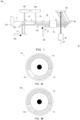
- FIG.1 is a schematic view of a projection device according to an embodiment of the disclosure.
- a projection device 10 provides a projection beam LP.
- the projection device 10 includes an illumination system 100, at least one light valve 50, a lens module 60 and a light uniformizing element 70, and the illumination system 100 provides an illumination beam LB.
- the light valve 50 is disposed on a transmitting path of the illumination beam LB and adapted to convert the illumination beam LB into at least one image beam LI.
- the lens module 60 is disposed on a transmitting path of the image beam LI and adapted to form the image beam LI into a projection beam LP, and the projection beam LP is projected onto a projection target (not shown) such as a screen or a wall surface.
- the light valve 50 is a reflective type light modulator such as a liquid crystal on silicon panel (LCoS panel), a digital micro-mirror device (DMD) or the like.
- the light valve 50 may be a transmissive type light modulator, such as a transparent liquid crystal panel, an electro-optical modulator, a magneto-optic modulator, an acousto-optic modulator (AOM) or the like.
- the disclosure provides no limitation to the form and type of the light valve 50. Details and implementation manners of the method for converting the illumination beam LB into the image beam LI by the light valve 50 will be omitted since sufficient teachings, suggestions and descriptions of implementation can be obtained from common knowledge in the art.
- the number of light valve 50 is one as in, for example, the projection device 10 using a single digital micro-mirror device, but the number of the light valve may be plural in other embodiments, the disclosure is not limited thereto.
- the projection lens 60 includes a combination of one or more optical lens having refractive powers, such as various combinations among non-planar lenses including a biconcave lens, a biconvex lens, a concave-convex lens, a convex-concave lens, a plano-convex lens and a plano-concave lens.
- the projection lens 60 may further include a planar optical lens to project the image beam LI from the light valve 50 to the projection target by the means of reflection.
- the disclosure provides no limitation to the form and type of the projection lens 60.
- the light uniformizing element 70 is disposed on the transmitting path of the illumination beam LB and adapted to adjust the speckle shape of the illumination beam LB, such that the speckle shape of the illumination beam LB coordinates the shape (e.g., rectangular shape) of an operation section of the light valve 50 and thus coherent or similar light intensity can be provided throughout the speckle, thereby uniformizing the light intensity of the illumination beam LB.
- the light uniformizing element 70 for example, is an integrator, but in other embodiments, the light uniformizing element 70 may be an optical element of other suitable type such as a fly eye lens array, which should not be construed as a limitation to the disclosure.
- the projection device 10 may further selectively include a reflecting element (mirror) 90.
- the reflecting element 90 guides the illumination beam LB emitted by the illumination system 100 to the light valve 50, but the disclosure is not limited thereto. In other embodiments, other optical elements may be used to guide the illumination beam LB to the light valve 50.
- the illumination system 100 includes a blue light source 110, an excitation light source 120, a first dichroic element 130, a wavelength converting element 140 and a filter element 150.
- the blue light source 110 provides a blue light beam L1
- the excitation light source 120 provides an excitation beam L2.
- the blue light source 110 and the excitation light source 120 are laser diode (LD), but in other embodiments, the blue light source 110 and the excitation light source 120 may be light emitting diode (LED) or organic light-emitting diode (OLED).
- the wavelength converting element 140 is, for example, a phosphor wheel
- the filter element 150 is, for example, a color wheel.
- the excitation light source 120 is a short-wavelength blue light source.
- the blue light beam L1 is a long-wavelength blue light beam and the excitation beam L2 is a short-wavelength blue light beam.
- the wavelength of the blue light beam L1 is greater than the wavelength of the excitation beam L2.
- the blue light beam L1 may have a wavelength of 460 nm
- the excitation beam L2 may have a wavelength of 445 nm.
- the embodiment uses the long-wavelength blue light beam (i.e., blue light beam L1) to provide the blue light portion of the projection beam LP, and uses the short-wavelength blue light beam (i.e., excitation beam L2) to excite the wavelength converting material of the wavelength converting element 140 to provide other color light such as yellow, green and red light portions of the projection beam LP.
- the problem of frame with purple-like blue color provided in known techniques can be avoided, thereby enhancing the optical property of the projection device 10.
- the first dichroic element 130 is disposed on the transmitting paths of the blue light beam L1 and the excitation beam L2, and the blue light source 110 and the excitation light source 120 are disposed on the same side of the first dichroic element 130.
- the blue light source 110 and the wavelength converting element 140 are disposed on two opposite sides of the first dichroic element 130.
- the first dichroic element 130 is a dichroic mirror which reflects yellow light, but the disclosure is not limited thereto. According to other embodiments, the first dichroic element 130 may be realized in other types or forms, further details are provided below along with other embodiments.
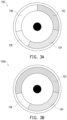
- FIG.2A is a schematic front view of a wavelength converting element of the projection device of FIG.1 .
- the wavelength converting element 140 is disposed on the transmitting path of the excitation beam L2
- the first dichroic element 130 is disposed between the excitation light source 120 and the wavelength converting element 140.
- the blue light source 110 and the wavelength converting element 140 are disposed on two opposite sides of the first dichroic element 130.
- the wavelength converting element 140 has a wavelength converting material (e.g., phosphor material) to convert the excitation beam L2 into an excited beam L3.
- a wavelength converting material e.g., phosphor material
- the wavelength converting element 140 includes a first converting section 142, a second converting section 144 and an optical section 146, wherein the first converting section 142 converts the excitation beam L2 into a first excited beam (yellow light), and the second converting section 144 converts the excitation beam L2 into a second excited beam (green light).
- the first converting section 142 is, for example, a yellow light converting material
- the second converting section 144 is, for example, a green light converting material, but the disclosure is not limited thereto.
- FIG.2B is a schematic front view of another wavelength converting element of the projection device of FIG.1.
- FIG.2B is different from FIG.2A in that, in the embodiment, an optical section 146A of a wavelength converting element 140A further includes a wavelength converting material, wherein the wavelength converting material of the optical section 146A is a green light converting material, but the disclosure is not limited thereto.
- the wavelength converting material in the optical section 146A may have the same concentration as the wavelength converting material in the second converting section 144; therefore, the wavelength converting material in the optical section 146A converts the excitation beam L2 into green light.
- the concentration of the wavelength converting materials may be different.
- the optical section 146A has a concentration of wavelength converting material less than the concentration of the wavelength converting material in the second converting section 144; therefore, the wavelength converting material in the optical section 146A converts the excitation beam L2 into cyan light.
- the wavelength converting maternal in the optical section 146A is a green light converting material, but the disclosure is not limited thereto.
- FIG.3A and FIG.3B are schematic front views of a filter element of the projection device of FIG.1 in different embodiments.
- the filter element 150 is disposed on the transmitting paths of the blue light beam L1 and the excited beam L3. Accordingly, when the excitation light source 120 is activated, the excitation beam L2 passes through the first dichroic element 130 to the wavelength converting element 140 and is converted into the excited beam L3, and the excited beam L3 is transmitted to the first dichroic element 130 and reflected to the filter element 150 to generate red light, green light or yellow light.
- the filter element 150 includes a first filter section 152, a second filter section 154, a diffusion section 156 and a light-transmissible section 158, wherein the excited beam L3 includes a first red light beam L4 and a green light beam L5, and the first filter section 152 allows the first red light beam L4 to pass through, the second filter section 154 allows the green light beam L5 to pass through.
- the diffusion section 156 of the filter element 150 may further include a filter coating.
- the filter coating allows blue light, green light or cyan light to pass through.
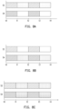
- FIG.4A to FIG.4C are timing period diagrams of the projection device in FIG.1 in different embodiments.
- the illumination system 100 has a first timing period, a second timing period, a third timing period and a fourth timing period when being operated, and the blue light source 110 and the excitation light source 120 are changed between on, off or power-saving state according to the timing periods, such that the light beam (i.e., illumination beam LB provided by illumination system) that is changed according to the timing period is received by the light valve 50 as shown in FIG.4A .
- the blue light source 110 is in the off state or power-saving state, and the excitation beam L2 emitted by the excitation light source 120 passes through the first dichroic element 130 to the first converting section 142 of the wavelength converting element 140 to generate a portion (i.e., first excited beam) of the excited beam L3.
- a portion of the excited beam L3 generated by the wavelength converting element 140 is transmitted to the first dichroic element 130 and reflected to pass through the first filter section 152 of the filter element 150 to generate a red light portion (i.e., first red light beam L4) of the illumination beam LB.
- the power-saving state is defined as that the light source is continuously in the on state but the intensity of emission of light becomes weak, or that the light beam is emitted after the light source is operated for a period of time, that is, the light source does not emit light beam although the light source has current or voltage.
- the blue light source 110 is in the off or power-saving state, and the excitation beam L2 emitted by the excitation light source 120 passes through the first dichroic element 130 to the second converting section 144 of the wavelength converting element 140 to generate another portion (i.e., second excited beam) of the excited beam L3.
- Another portion of the excited beam L3 generated by the wavelength converting element 140 is transmitted to the first dichroic element 130 and reflected to pass through the second filter section 154 of the filter element 150 to generate the green light portion (i.e., green light beam L5) of the illumination beam LB.
- the excitation light source 120 is in the off state or power-saving state, and the blue light beam L1 emitted by the blue light source 110 sequentially passes through the first dichroic element 130 and the diffusion section 156 of the filter element 150 to generate the blue light portion of the illumination beam LB.
- the blue light portion of the illumination beam LB may achieve diffusion uniforming by passing through the diffusion section 156.
- the diffusion section 156 eliminates the laser speckle on the projection target that is irradiated by the blue light portion of the illumination beam LB.
- the blue light source 110 is in the off state of the power-saving state, and the excitation beam L2 emitted by the excitation light source 120 passes through the first dichroic element 130 to the first converting section 142 of the light wavelength converting element 140 to generate a portion (i.e., first excited beam) of the excited beam L3.
- a portion of the excited beam L3 generated by the wavelength converting element 140 is transmitted to the first dichroic element 130 and reflected to pass through the light-transmissible section 158 of the filter element 150 to generate yellow light beam (not shown). Therefore, at the fourth timing period of the embodiment, the excitation light source 120 may further provide the yellow light beam to the light valve 50, such that the projection beam LP provided by the projection device 10 has better brightness and accurate color.
- the blue light source 110 and the excitation light source 120 may be in the on state simultaneously. Specifically, the blue light beam L1 emitted by the blue light source 110 sequentially passes through the first dichroic element 130 and the light-transmissible section 158 of the filter element 150 to generate the blue light portion of the illumination beam LB.
- the excitation beam L2 emitted by the excitation light source 120 passes through the first dichroic element 130 to the first converting section 142 of the wavelength converting element 140 to generate a portion of the excited beam L3, and a portion of the excited beam L3 generated by the wavelength converting element 140 is transmitted to the first dichroic element 130 and reflected to pass through the light-transmissible section 158 of the filter element 150 to generate the yellow light beam.
- the blue light portion provided by the blue light source 110 and the yellow light portion provided by the excitation light source 120 are mixed as white light. In this manner, the projection beam LP provided by the projection device 10 has better brightness and optical quality.
- the embodiment is different from the above embodiment in that, in the embodiment, the filter element 150 of the illumination system 100 may be changed into a filter element 150A, and the illumination system 100 only has the first timing period (t0-t1 or t3-t4), the second timing period (t1-t2 or t4-t5) and the third timing period (t3-t4 or t5-t6).
- the blue light source 110 and the excitation light source 120 are respectively changed between the on, off or power-saving state according to the timing periods, such that the light beam (i.e., illumination beam LB provided by the illumination system) that is changed according to timing periods is received by the light valve 50 as shown in FIG.4C .
- the illumination system in the embodiment at the first timing period, the second timing period and the third timing period is similarly operated as in the above embodiment at the first timing period, the second timing period and the third timing period; the difference between the two is that the filter element 150A in the embodiment only includes the first filter section 152, the second filter section 154 and the diffusion section 156. Accordingly, the illumination system 100 in the embodiment provides the red light portion, the green light portion and the blue light portion of the illumination beam LB at the first timing period, the second timing period and the third timing period respectively. Details and implementation manners of the above steps will be omitted since sufficient teachings, suggestions and descriptions of implementation can be obtained from common knowledge in the art.
- the illumination system 100 has a first timing period, a second timing period, a third timing period and a fourth timing period in operation, and the blue light source 110 and the excitation light source 120 are changed between the on, off or power-saving state respectively according to the timing periods, such that the light beam (i.e., illumination beam LB provided by the illumination system) that is changed according to the timing periods is received by the light valve 50 as shown in FIG.4A .
- the light beam i.e., illumination beam LB provided by the illumination system
- the blue light source 110 is in the off state or the power-saving state, and the excitation beam L2 emitted by the excitation light source 120 passes through the first dichroic element 130 to the first converting section 142 of the wavelength converting element 140 to generate a portion (i.e., first excited light beam) of the excited beam L3.
- a portion of the excited beam L3 generated by the wavelength converting element 140 is transmitted to the first dichroic element 130 and reflected to pass through the first filter section 152 of the filter element 150 to generate the red light portion (i.e., first red light beam L4) of the illumination beam LB.
- the blue light source 110 is in the off state of the power-saving state, and the excitation beam L2 emitted by the excitation light source 120 passes through the first dichroic element 130 to the second converting section 144 of the wavelength converting element 140 to generate another portion (i.e., second excited beam) of the excited beam L3.
- Another portion of the excited beam L3 generated by the wavelength converting element 140 is transmitted to the first dichroic element 130 and reflected to pass through the second filter section 154 of the filter element 150 to generate the green light portion (i.e., green light beam L5) of the illumination beam LB.
- the excitation light source 120 is in the on state, and the blue light source 110 is in the on state.
- the excitation beam L2 emitted by the excitation light source 120 passes through the first dichroic element 130 to the optical section 146A of the wavelength converting element 140 to generate another portion (i.e., third excited beam, e.g., green light or cyan light) of the excited beam L3, and simultaneously transmitted to the diffusion section 156 of the filter element 150 along with the blue light beam L1 emitted by the blue light source 110.
- the third excited beam and the blue light beam L1 are used to generate the blue light portion of the illumination beam LB.
- the color coordinate of the blue light can be adjusted such that the color of the projection beam LP is more saturated to exhibit the real color of image.
- the intensity of the excitation beam L2 emitted by the excitation light source 120 is the same as the intensity of the blue light beam L1 emitted by the blue light source 110, which coordinates that the wavelength converting material in the optical section 146A has the same concentration as the wavelength converting material in the second converting section 144.
- the intensity of the excitation beam L2 emitted by the excitation light source 120 is the same as the intensity of the blue light beam L1 emitted by the blue light source 110, which coordinates that the optical section 146A has a concentration of the wavelength converting material different from the wavelength converting material in the second converting section 144.
- the intensity of the excitation beam L2 emitted by the excitation light source 120 is different from the intensity of the blue light beam L1 emitted by the blue light source 110.
- the intensity of the excitation beam L2 emitted by the excitation light source 120 is weaker than the intensity of the blue light beam L1 emitted by the blue light source 110, which coordinates that the optical section 146A has the same concentration of the wavelength converting material as the wavelength converting maternal in the second converting section 144.
- the purpose of the above embedment is to adjust the color coordinate of blue light such that the color of the projection beam LP is more saturated to exhibit the real color of image.
- the blue light source 110 is in the off state or the power-saving state, and the excitation beam L2 emitted by the excitation light source 120 passes through the first dichroic element 130 to the first converting section 142 of the wavelength converting element 140 to generate a portion (i.e., first excited beam) of the excited beam L3.
- a portion of the excited beam L3 generated by the wavelength converting element 140 is transmitted to the first dichroic element 130 and reflected to pass through the light-transmissible section 158 of the filter element 150 to generate the yellow light beam (not shown).
- the excitation light source 120 may further provide the yellow light beam to the light valve 50 such that the projection beam LP provided by the projection device 10 has better brightness and accurate color. Details and implementation manners of the above steps will be omitted since sufficient teachings, suggestions and descriptions of implementation can be obtained from common knowledge in the art.
- the illumination system 100 further includes a red light source 160 and a second dichroic element 170.
- the red light source 160 is, for example, a red laser diode or a red light-emitting diode, which is used to provide a second red light beam L6.
- the second dichroic element 170 is a dichroic mirror that reflects red light and allows the blue light beam L1 to pass through.
- the second dichroic element 170 is disposed on transmitting paths of the blue light beam L1 and the second red light beam L6.
- the red light source 160 is activated at the first timing period in any one of the above embodiments to provide a second red light beam L6, and the second red light beam L6 is transmitted to the second dichroic element 170 and reflected to the first filter section 152, thereby providing additional red light portion of the illumination beam LB.
- the projection beam LP provided by the projection device 10 has better color saturation and optical quality.
- the red light source 160 and the second dichroic element 170 are disposed between the first dichroic element 130 and the filter element 150, which should not be construed as a limitation to the disclosure.
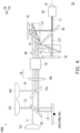
- FIG.5 is a schematic view of a projection device according to another embodiment of the disclosure.
- a projection device 10A in the embodiment is similar to the projection device 10 in FIG.1 , and the difference between the two is that, in the embodiment, the red light source 160 and the second dichroic element 170 of the illumination system 100A are disposed between the blue light source 110 and the first dichroic element 130.
- the second light beam L6 provided by the red light source 160 is transmitted to the second dichroic element 170 and reflected to pass through the first dichroic element 130 and the first filter section 152, thereby providing additional red light portion of the illumination beam LB.
- the first dichroic element 130 and the second dichroic element 170 are disposed in a non-parallel manner.
- An included angle is formed between an extending line of the first dichroic element 130 and an extending line of the second dichroic element 170, and the included angle is approximately 90 degrees.
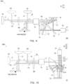
- FIG.6 is a schematic view of a projection device according to another embodiment of the disclosure.
- FIG.7A and FIG.7B are schematic front views of a wavelength converting element of the projection device in FIG.6 in different embodiments.
- FIG.8A and FIG.8B are timing period diagrams showing the projection device in FIG.6 in different embodiments.
- a projection device 20 in the embodiment is similar to the projection device 10 in FIG.1 . The difference between the two is that, in the embodiment, at least one light valve 50 of the protection device 20 includes a first light valve 52 and a second light valve 54, and is, for example, a projection device 20 using two digital micro-mirror devices.
- the projection device 20 further includes at least one dichroic mirror 80, which is disposed on the transmitting path of the excited beam L3 and adapted to allow one of the first red light beam L4 and the green light beam L5 to pass through and transmitted to the first light valve 52, and the other one is reflected through the dichroic mirror 80 and transmitted to the second light valve 54.
- An illumination system 100B further includes a diffuser 180 disposed on the transmitting path of the blue light beam L1 to uniformize diffusion of the blue light beam L1.
- the illumination system 100B has the first timing period (t0-t1 or t2-t3) and the second timing period (t1-t2 or t3-t4) in operation, and the blue light source 110 and the excitation light source 120 are changed between the on, off or power-saving state respectively according to the timing periods, such that the light beam (i.e., illumination beam LB provided by the illumination system) that is changed according to timing periods is received by first light valve 52 and the second light valve 54 as shown in FIG.8A .
- the blue light source 110 is in the on state or the power-saving state, and the excitation beam L2 emitted by the excitation light source 120 passes through the first dichroic element 130 to the first converting section 142 of the wavelength converting element 140A to generate the excited beam L3 as shown in FIG.7A .
- the excited beam L3 generated by the wavelength converting element 140A is transmitted to the first dichroic element 130 and reflected to pass through the diffusor 180 to generate the red light portion and the green light portion (i.e., first red light beam L4 and green light beam L5) of the illumination beam LB.
- the red light portion and the green light portion of the illumination beam LB are transmitted to the dichroic mirror 80, the red light portion of the illumination beam LB passes through the dichroic mirror 80 and transmitted to the first light valve 52, and the green light portion of the illumination beam LB is reflected by the dichroic mirror 80 and transmitted to the second light valve 54 as shown in FIG.8A .
- a first sub-image beam LI1 and a second sub-image beam LI2 generated by the first light valve 52 and the second light valve 54 are combined by a combining element 82 into a portion of the image beam LI and transmitted to the lens module 60, that is, the combining element 82 reflects the first sub-image beam LI1 and allows the second sub-image beam LI2 to pass through and transmitted to the lens module 60.
- the red light portion of the illumination beam LB may be reflected by the dichroic mirror 80 and transmitted to the second light valve 54, and the green light portion of the illumination beam LB may be transmitted to the first light valve 52 by the dichroic mirror 80, but the disclosure provides no limitation thereto.
- the excitation light source 120 is in the off state of the power-saving state, and the blue light beam L1 emitted by the blue light source 110 sequentially passes through the first dichroic element 130 and diffusor 180 to generate the blue light portion of the illumination beam LB and transmitted to the first light valve 52 through the dichroic mirror 80.
- the blue light portion of the illumination beam LB is reflected by the dichroic mirror 80 and transmitted to the second light valve 54 as shown in FIG.8B .
- the blue light portion of the illumination beam LB may achieve diffusion uniforming by passing through the diffusor 180.
- the blue light portion of the illumination beam LB passes through the dichroic mirror 80 and transmitted to the first light valve 52 to form a portion of the first sub-image beam LI1, the combining element 82 allows a portion of the first sub-image beam LI1 to be reflected and transmitted to the lens module 60.
- the blue light portion of the illumination beam LB may be reflected and transmitted to the second light valve 54 by the dichroic mirror 80, but the disclosure is not limited thereto.
- the wavelength converting element 140A includes the first converting section 142 and the optical section 146.
- the optical section 146A does not receive the excitation beam L2 from the excitation light source 12 and thus a portion of the wavelength converting material can be saved.
- the wavelength converting element 140A may be changed into a wavelength converting element 140B which is only be provided with the first converting section 142 having the wavelength converting material to simplify the manufacturing process of the wavelength converting element 140A as shown in FIG.7B , but the disclosure is not limited thereto.
- the illumination system 100B may further include the red light source 160 and the second dichroic element 170.
- the second dichroic element 170 is a dichroic mirror that reflects red light and disposed on the transmitting paths of the blue light beam L1 and the second red light beam L6.
- the red light source 160 is activated at the first timing period of the above embodiment to provide the second red light beam L6, and the second red light beam L6 is transmitted to the second dichroic element 170 and reflected to the diffusor 180, thereby providing additional red light portion of the illumination beam LB.
- the projection beam LP provided by the projection device 20 has better color saturation and optical quality.
- the red light source 160 and the second dichroic element 170 are disposed between the first dichroic element 130 and the diffusor 180, but the disclosure is not limited thereto.
- FIG.7C is a schematic front view of another wavelength converting element of the projection device in FIG.6 .
- FIG.7C is different from FIG.7A in that, in the embodiment, the optical section 146A of the wavelength converting element 140C further includes a wavelength converting material, wherein the wavelength converting material in the optical section 146A is a green light converting material, but the disclosure is not limited thereto.
- the wavelength converting material in the optical section 146A converts the excitation beam L2 into green light or cyan light, but the disclosure is not limited thereto.
- the illumination system 100B has a first timing period (t0-t1 or t2-t3) and the second timing period (t1-t2 or t3-t4) in operation, and the blue light source 110 and the excitation light source 120 are changed between the on, off or power-saving state according to the timing periods respectively, such that the light beam (i.e., illumination beam LB provided by illumination system) that is changed according to timing periods is received by the first light valve 52 and the second light valve 54 as shown in FIG.8C .
- the light beam i.e., illumination beam LB provided by illumination system
- the blue light source 110 is in the off state of the power-saving state, and the excitation beam L2 emitted by the excitation light source 120 passes through the first dichroic element 130 to the first converting section 142 of the wavelength converting element 140C to generate the excited beam L3 as shown in FIG.7C .
- the excited beam L3 generated by the wavelength converting element 140C is transmitted to the first dichroic element 130 and reflected to pass through the diffusor 180 to generate the red light portion and green light portion (i.e., first red light beam L4 and green light beam L5) of the illumination beam LB.
- the red light portion and the green light portion of the illumination beam LB are transmitted to the dichroic mirror 80, the red light portion of the illumination beam LB passes through the dichroic mirror 80 and transmitted to the first light valve 52, and the green light portion of the illumination beam LB is reflected by the dichroic mirror 80 and transmitted to the second light valve 54 as shown in FIG.8C .
- the excitation light source 120 is in the on state, and the blue light source 110 is in the on state.
- the excitation beam L2 emitted by the excitation light source 120 passes through the first dichroic element 130 to the optical section 146A of the wavelength converting element 140C to generate another portion (i.e., third excited beam such as green light or cyan light) of the excited beam L3, and simultaneously transmitted to the diffusor 180 along with the blue light beam L1 emitted by the blue light source 110 to generate the blue light portion of the illumination beam LB, wherein the blue light beam L1 passes through the dichroic mirror 80 and transmitted to the first light valve 52, and another portion (i.e., third excited beam such as green light or cyan light) of the excited beam L3 is reflected by the dichroic mirror 80 and transmitted to the second light valve 54.
- the purpose of the embodiment is to adjust the color coordinate of blue light such that the color of the projection beam LP is more saturated to exhibit the real color of image
- FIG.9 is a schematic view of a projection device according to another embodiment of the disclosure.
- a projection device 20A in the embodiment is similar to the projection device 20 in FIG.6 , and the difference between the two is that, in the embodiment, the red light source 160 and the second dichroic element 170 of an illumination system 100C are disposed between the blue light source 110 and the first dichroic element 130. Accordingly, the second red light beam L6 provided by the red light source 160 is transmitted to the second dichroic element 170 and reflected to pass through the diffusor 180 and the first dichroic element 130, thereby providing the additional red light portion of the illumination beam LB.
- the diffusor 180 may be disposed between the second dichroic element 170 and the first dichroic element 130.
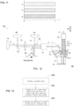
- FIG.10 is a schematic view of a projection device according to another embodiment of the disclosure.
- FIG.11 is a timing period diagram showing the projection device in FIG.10 .
- a projection device 30 in the embodiment is similar to the projection device 20 in FIG.6 , and the difference between the two is that, in the embodiment, at least one light valve 50 of the projection device 30 includes the first light valve 52, the second light valve 54 and a third light valve 56, and is, for example, a projection device 30 using three digital micro-mirror devices.
- the blue light source 110 and the excitation light source 120 are simultaneously in the on, off or power-saving state, such that the light beam (i.e., illumination beam LB provided by illumination system) is received by the first light valve 52, the second light valve 54 and the third light valve 56 as shown in FIG.1 1 .
- the light beam i.e., illumination beam LB provided by illumination system
- the illumination beam LB provided by the illumination system 100B generates a mixing beam L7 after passing through the uniformizing element 70.
- the mixing beam L7 (e.g., white light) can be formed respectively through the dichroic function of different optical elements (e.g., dichroic prism) in the projection device 30, and provide the blue light beam L1, the green light beam L5 and the first red light beam L4 to the first light valve 52, the second light valve 54 and the third light valve 56 to be formed into the first sub-image beam LI1, the second sub-image beam LI2 and the third sub-image light LI3 by the first light valve 52, the second light valve 54 and the third light valve 56 respectively and transmitted to the lens module 60.
- different optical elements e.g., dichroic prism
- the red light source 160 and the second dichroic element 170 as shown in FIG.6 may be adapted in order to provide the projection beam LP having better color saturation and optical quality in the circumstances where color performance is emphasized (e.g., home theater circumstances). Details and implementation manners of the method for configuring the red light source 160 and the second dichroic element 170 to provide the second red light beam L6 in order to replace the first red light beam L4 in the excited beam L3 will be omitted since sufficient teachings, suggestions and descriptions of implementation can be obtained from common knowledge in the art.
- FIG.12 is a schematic view of a projection device according to another embodiment of the disclosure.
- a projection device 30A in the embodiment is similar to the projection device 30 in FIG.10 , and the difference between the two is that, in the embodiment, the red light source 160 and the second dichroic element 170 of the illumination system 100C are disposed between the blue light source 110 and the first dichroic element 130. Therefore, the second red light beam L6 provided by the red light source 160 is transmitted to the second dichroic element 170 and reflected to pass through the diffusor 180 and the first dichroic element 130, thereby providing additional red light portion of the illumination beam LB.
- the diffusor 180 is disposed between the second dichroic element 170 and the first dichroic element 130.
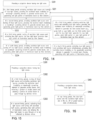
- FIG.13 is a flowchart of an operating method of a projection device according to an embodiment of the disclosure.
- the operating method in the embodiment is used for the projection device described in any one of the above embodiments, but the disclosure is not limited thereto.
- the projection device described in the above embodiment is provided, for example, a projection device having one light valve, two light valves and three light valves is provided.
- step S210 the on, off or power-saving state of the blue light source and excitation light source is changed respectively according to different timing periods. In other words, in the process of operating the projection device, the on, off or power-saving state of the blue light source and excitation light source is changed respectively according to a specific cycle.
- the blue light source having longer wavelength may be used to provide the blue light portion of the illumination beam, and the excitation light source is used to provide the red light and green light portions of the illumination beam, thereby improving the problem of purple-like blue color in projection frame and enhancing optical quality of the projection beam of the projection device and saturation of image color.
- the red light source may further be added to provide additional red light portion of the illumination beam. In this manner, in the circumstances where color performance is emphasized (e.g., home theater circumstances), the projection beam provided by the projection device has better color saturation and optical quality.
- FIG.14 is a flowchart of an operating method of a projection device according to another embodiment of the disclosure. More specifically, referring to FIG.1, FIG.2A , FIG.3B , FIG.13 and FIG.14 , in step S201, the number of light valve 50 in the projection device is one, which coordinates the wavelength converting element 140 and the filter element 150A, and a method of changing the blue light source and the excitation light source according to different timing periods may include: step S221, at the first timing period, the excitation light source 120 is activated and the blue light source 110 is turned off, the excitation beam L2 is irradiated on the wavelength converting element 140 to generate the excited beam L3, thereby generating the red light portion L4 of the illumination beam LB by the filter element 150; in step S222, at the second timing period, the excitation light source 120 is activated and the blue light source 110 is turned off, the excitation beam L2 is irradiated on the wavelength converting element 140 to generate the excited beam L3, thereby generating the green light
- the wavelength converting element 140 and the filter element 150 are used for coordination.
- the fourth timing period is added, in step S224, at the fourth timing period, the excitation light source 110 is activated and the blue light source 120 is turned off.
- the excitation beam L2 is irradiated on the wavelength converting element 140 to generate the excited beam L3.
- the yellow light portion of the illumination beam LB is generated by the filter element 150, thus exhibited according to the timing period as shown in FIG.4A .
- the blue light source and the excitation light source are activated simultaneously at the fourth timing period to generate the white light portion of the illumination beam LB, thus exhibited according to the timing period as shown in FIG.4B .
- the wavelength converting element 140A and the filter element 150 or filter element 150A are used for coordination.
- the optical section 146A of the wavelength converting element 140A further includes a wavelength converting material, and the diffusion section 156 of filter assembly (150, 150A) may further include a filter coating.
- the method for changing the blue light source and excitation light source according to different timing periods may include: step S226, at the third timing period, the excitation light source 110 is activated and the blue light source 120 is activated.
- the excitation beam L2 is irradiated on the wavelength converting element 140 to generate the third excited beam (e.g., green light or cyan light).
- the third excited beam and the blue light beam L1 generate the blue light, green light or cyan light portion of the illumination beam LB by the filter element (150, 150A), but the disclosure is not limited thereto.
- the method for changing the blue light source and excitation light source according to different timing periods further includes: step S227, at the third timing period, the intensity of the activated excitation light source 110 and the intensity of the activated blue light source 120 are the same, that is, the intensity of the excitation beam L2 and the intensity of the blue light beam L1 are the same, e.g., the intensity is the same as current or voltage.
- the wavelength converting element 140A having the optical section 146A with wavelength converting material is provided, wherein the wavelength converting material in the optical section 146A has the same concentration as the wavelength converting material in the second converting section 144.
- the intensity of the activated excitation light source 110 and the intensity of the activated blue light source 120 are the same.
- the wavelength converting element 140A having the optical section 146A with wavelength converting material is provided, wherein the concentration of wavelength converting material in the optical section 146A is different from the wavelength converting material in the second converting section 144.
- the method for changing the blue light source and the excitation light source according to different timing periods further includes: step S228, the intensity of the activated excitation light source 110 and the intensity of the activated blue light source 120 are different.
- the wavelength converting element 140A having the optical section 146A with the wavelength converting material is provided, wherein the wavelength converting material in the optical section 146A has the same concentration as the wavelength converting material in the second converting section 144.
- FIG.15 is a flowchart of an operating method of a projection device according to yet another embodiment of the disclosure.
- the method for changing the blue light source and the excitation light source according to different timing periods may include: step S302, at the first timing period, the excitation light source 120 is activated and the blue light source 110 is turned off.
- the excitation beam L2 is irradiated on the wavelength converting element (140A, 140B) to generate the excited beam L3, and the dichroic mirror 80 is used to reflect a portion of the excited beam L3 and allows a portion of the excited beam L3 to pass through.
- the dichroic mirror 80 is used to allow the red light beam L4 of the excited beam L3 to pass through and reflect the green light beam L5 of the excited beam L3, but the disclosure is not limited thereto.
- the dichroic mirror 80 reflects the red light beam L4 of the excited beam L3 and allows the green light beam L5 of the excited beam L3.
- step S303 at the second timing period, the blue light source 110 is activated and the excitation light source 120 is turned off, thereby generating the blue light portion of the illumination beam; the dichroic mirror 80 is used to allow the blue light beam L1 to pass through, but the disclosure is not limited thereto. In other embodiments, the dichroic mirror 80 is used to reflect the blue light beam L1.
- the timing period shown in FIG.8C additionally, referring to FIG.6 , FIG.7C , FIG.8C and FIG.13 , in one embodiment, it is also possible to activate the blue light source 110 and excitation light source 120 at the second timing period, and the wavelength converting element 140C in FIG.7C is used for coordination to simultaneously generate the blue light portion of the illumination beam and the green light or cyan light portion of the excited beam, but the disclosure is not limited thereto. In this manner, the problem of purple-like blue light in the projection frame may be improved, thereby enhancing optical quality of projection beam of projection device and saturation of image color.
- FIG.16 is a flowchart of an operating method of a projection device according to still another embodiment of the disclosure.
- the number of the light valve 50 in the projection device is three, and the wavelength converting assembly (140A, 140B, 140C) is used for coordination.
- the method for changing the blue light source and the excitation light source according to different timing periods may include: the on, off or power-saving state of the blue light source 110 and the excitation light source 120 does not need to be changed according to different timing periods; in step S402, the blue light source 110 and the excitation light source 120 are in the on, off or power-saving state simultaneously, such that the light beam (i.e., illumination beam LB provided by illumination system) is received by the first light valve 52, the second light valve 54 and the third light valve 56 as shown in FIG.11 .
- the light beam i.e., illumination beam LB provided by illumination system
- the embodiments of the disclosure at least have one of the following advantages or effects.
- the illumination system uses blue light source to provide the blue light portion of the illumination beam and uses excitation light source to provide the red light portion and green light portion of the illumination beam. Accordingly, the blue light source having longer wavelength may improve the purple-like blue color in the projection frame, thereby enhancing the optical quality of the projection device.
Description
- This application claims the priority of
China application serial no. 201810402606.6, filed on April 28, 2018 - The disclosure is related to an optical system, an optical device and an operating method thereof, and particularly to an illumination system, a projection device and operating method thereof.
- A projection device is a display device used for generating large-size frame, and has been continuously evolved and developed along with new technologies. The principle for projection device to form image is to convert an illumination beam generated by illumination system into an image beam through a light valve, and project the image beam onto a projection target (e.g., screen or wall surface) through a projection lens to form a projection frame.
- Additionally, in order to meet the market's expectations for the brightness, color saturation, lifespan, being non-poisonous and environmental and so on, illumination system has been evolved from original ultra-high-performance lamp (UHP lamp) which belongs to ultra-high-voltage mercury lamp to light-emitting diode (LED), and now the most advanced laser diode (LD) light source is developed. However, in illumination system, typical method for generating red and green light with reasonable cost utilizes blue LD to excite the phosphor powder of fluorescence wheel to generate yellow green light. Then, the required red light or green light is filtered by using optical element to be put in use.
- However, in typical illumination system configuration, considering that exciting phosphor powder requires the use of blue light source having shorter wavelength, the blue color exhibited in projection is shown as a purple-like color to human eyes, and the purple-like blue color affects visual effect.
-
US 2015/029467 A1 presents a light source unit and projector. A small light source unit is provided which emits lights of the primary colors which are highly bright and which have a high color reproducibility and excitation light, and the light source unit includes a light source module and a light source control module and the light source module has a first light source which emits light having a first wavelength which is used as excitation light which excites a luminescent material, and a second light source which emits light having a second wavelength which is different from the first wavelength but which falls within a range of wavelengths of light of a similar color to that of the light of the first light source, and the light source control module controls individually the illumination of the first light source and the second light source. -
US 2018/080630 A1 presents a light-emitting device that includes a light source module comprising an excitation light source for emitting exciting light and a compensation light source for emitting compensation light; and a color wheel component comprising at least one segmented region distributed in a motion direction of the color wheel component. The color wheel component emits the compensation light and first light that comprises at least one beam of excited light under irradiation of the excitation light source and the compensation light source. The compensation light spectrally overlaps the at least one beam of excited light in the first light, and the compensation light and the excited light spectrally overlapping the compensation light are simultaneously emitted and are independently adjustable. A projection system comprising a light emitting device is further provided. -
WO 2016/158297 A1 presents a projector and image optical projection method. Provided is a field sequential projector comprising: a plurality of light sources which output primary color light having a peak wavelength in a primary color wavelength region, each light source having a different peak wavelength in the primary color wavelength region; an illumination optical system which has a video image formation element that spatially modulates the primary color light output from the plurality of light sources to form image light, the illumination optical system guiding the primary color light output from the plurality of light sources to the video image formation element; and a projection optical system that projects the image light formed by the video image formation element. -
US 2013/083294 A1 presents an illumination system, including a blue incoherent light source, a coherent light source, a phosphor module and a beam combining unit. The blue incoherent light source is capable of emitting a blue incoherent light beam. The coherent light source is capable of emitting a coherent light beam. The phosphor module has a first color phosphor zone and a second color phosphor zone. The first color phosphor zone and the second color phosphor zone move into a transmission path of the coherent light beam in turn, to convert the coherent light beam to a first color light beam and a second color light beam respectively. The beam combining unit is disposed on transmission paths of the blue incoherent light beam, the first color light beam and the second color light beam. A projection apparatus is also provided. - The information disclosed in this "Description of Related Art" section is only for enhancement of understanding of the "Description of Related Art" section of the described technology and therefore it may contain information that does not form the prior art that is already known to a person of ordinary skill in the art. Further, the information disclosed in the "Description of Related Art" section does not mean that one or more problems to be resolved by one or more embodiments of the disclosure were acknowledged by a person of ordinary skill in the art.
- An embodiment of the disclosure provides an illumination system, a projection device and an operating method thereof, capable of improving the problem of purple-like blue light beam.
- The objectives and advantages of the disclosure may be further understood in the technical features disclosed in the disclosure.
- The object is solved by the features of the independent claims. Preferred embodiments are given in the dependent claims.
- To achieve one or a part or all the objectives or other objectives, an embodiment of the disclosure provides an illumination system including a blue light source, an excitation light source, a first dichroic element and a wavelength converting element. The blue light source provides a blue light beam. The excitation light source provides an excitation beam. The first dichroic element is disposed on transmitting paths of the blue light beam and the excitation beam. The wavelength converting element is disposed on the transmitting path of the excitation beam and adapted to convert the excitation beam into an excited beam, wherein the excitation beam passes through the first dichroic element to the wavelength converting element and is converted into an excited beam. The excited beam is transmitted to the first dichroic element and reflected. The wavelength of the blue light beam is greater than the wavelength of the excitation beam, and the blue light source and the excitation light source are disposed on the same side of the first dichroic element.
- In some embodiments, the illumination system may further comprise a filter element, disposed on the transmitting paths of the blue light beam and the excited beam.
- Preferably, the filter element may comprise a first filter section, a second filter section and a diffusion section.
- Preferably, at a first timing period, the blue light source is in an off state or a power-saving state, the excitation beam is transmitted to a first converting section of the wavelength converting element to be converted into a first exited beam, and the first excited beam passes through the first filter section to generate a first red light beam, at a second timing period, the blue light source is in the off state or the power-saving state, the excitation beam is transmitted to a second converting section of the wavelength converting element to be converted into a second excited beam, and the second excited beam passes through the second filter section to generate a green light beam, at a third timing period, the excitation light source is in the off state or the power-saving state, and the blue light beam passes through the diffusion section, wherein the excited beam comprises the first excited beam and the second excited beam.
- In some embodiments, the illumination system may further comprise a red light source, adapted to provide a second red light beam.
- Preferably, the illumination system may further comprise a second dichroic element, disposed on transmitting paths of the blue light beam and the second red light beam.
- Preferably, the red light source is activated at the first timing period.
- Preferably, the second red light beam is transmitted to the second dichroic element and reflected to the first filter section of the filter element.
- Preferably, the red light source and the second dichroic element are disposed between the blue light source and the first dichroic element.
- Preferably the first dichroic element and the second dichroic element are disposed in a non-parallel manner.
- Preferably, an included angle is formed between an extending line of the first dichroic element and an extending line of the second dichroic element.
- Preferably the filter element further comprises a light-transmissible section.
- Preferably, at a fourth timing period, the excitation beam passes through the first dichroic element to the first converting section of the wavelength converting element and is converted into the excited beam, and the excited beam passes through the light-transmissible section.
- Preferably, the wavelength converting element further comprises an optical section.
- Preferably, the optical section does not receive the excitation beam.
- Preferably, the optical section has a wavelength converting material.
- In some embodiments, the illumination system may further comprise a filter element, disposed on the transmitting paths of the blue light beam and the excitation beam.
- Preferably, the filter element comprising a first filter section, a second filter section and a diffusion section.
- Preferably, at a first timing period, the blue light source are in an off state or a power-saving state, the excitation beam is transmitted to a first converting section of the wavelength converting element to be converted into a first excited beam, and the first excited beam passes through the first filter section to generate a first red light beam, at a second timing period, the blue light source is in the off state or the power-saving state, the excitation beam is transmitted to a second converting section of the wavelength converting element to be converted into a second excited beam, and the second excited beam passes through the second filter section to generate a green light beam, at a third timing period, the excitation light source is in an on state, the blue light source is activated, the excitation beam passes through the first dichroic element to the optical section of the wavelength converting element to generate a third excited beam, and is simultaneously transmitted to the diffusion section along with the blue light beam and passes through the diffusion section.
- Preferably, the illumination system may further comprise a diffusor, disposed on the transmitting path of the blue light beam, wherein at a first timing period, the blue light source is in an off state or a power-saving state, the excitation beam passes through the first dichroic element to a first converting section of the wavelength converting element and converted into the excited beam, and the excited beam is transmitted to the first dichroic element and reflected to the diffusor, at a second timing period, the excitation light source is in an off state or a power-saving state, the blue light beam passes through the first dichroic element and the diffusor, wherein the excited beam comprises a first red light beam and a green light beam.
- Preferably, the wavelength converting element further comprises an optical section, the optical section does not receive the excitation beam.
- Preferably, the illumination system may further comprise a diffusor, disposed on the transmitting path of the blue light beam, wherein at a first timing period, the blue light source is in an off state or a power-saving state, the excitation beam passes through the first dichroic element to a first converting section of the wavelength converting element and converted into the excited beam, and the excited beam is transmitted to the first dichroic element to be reflected to the diffusor, at a second timing period, the excitation light source is in an on state, and the blue light source is in an on state, the excitation beam passes through the first dichroic element to the optical section of the wavelength converting element and is converted into a third excited beam, and the third excited beam is transmitted to the first dichroic element and reflected to the diffusor, the blue light beam passes through the first dichroic element and transmitted to the diffusor.
- Preferably, the illumination system may further a red light source, adapted to provide a second red light beam.
- Preferably, the illumination system may further comprise a second dichroic element, disposed on the transmitting paths of the blue light beam and the second red light beam.
- Preferably, the red light source is activated at the first timing period, and the second red light beam is transmitted to the second dichroic element to be reflected to the diffusor.
- Preferably, the red light source and the second dichroic element are disposed between the diffusor and the first dichroic element.
- Preferably the red light source, the second dichroic element and the diffusor are disposed between the blue light source and the first dichroic element.
- Preferably, the excited beam comprises a first red light beam and a green light beam.
- Preferably, the illumination system may further comprise a red light source, adapted to provide a second red light beam; a diffusor, disposed on transmitting paths of the blue light beam and the second red light beam; and a second dichroic element, disposed on the transmitting paths of the blue light beam and the second red light beam, and disposed between the blue light source and the diffusor, wherein the blue light source, the excitation light source and the red light source are simultaneously in an on state, an off state or a power-saving state.
- Preferably, the blue light beam is a blue light beam having a wavelength of 460 nm, and the excitation light beam is a blue light beam having a wavelength of 445 nm.
- Preferably, the blue light source and the wavelength converting element are disposed on opposite sides of the first dichroic element respectively.
- To achieve one or a part or all the objectives or other objectives, another embodiment of the disclosure provides a projection device for providing a projection beam. The projection device includes an illumination system, at least one light valve and one lens module. The illumination system provides an illumination beam. The illumination system includes a blue light source, an excitation light source, a first dichroic element and a wavelength converting element. The blue light source provides a blue light beam. The excitation light source provides an excitation beam. The first dichroic element is disposed on transmitting paths of the blue light beam and excitation beam. The wavelength converting element is disposed on the transmitting path of the excitation beam and adapted to convert the excitation beam into an excited beam, wherein the excitation beam passes through the first dichroic element to the wavelength converting element and is converted into an excited beam. The excited beam is transmitted to the first dichroic element and reflected. At least one light valve is disposed on the transmitting path of the illumination beam and adapted to convert the illumination beam into at least one image beam. The lens module is disposed on the transmitting path of at least one image beam and adapted to form the at least one image beam into a projection beam, wherein the wavelength of the blue light beam is greater than the wavelength of the excitation beam, and the blue light source and the excitation light source are disposed on the same side of the first dichroic element.
- In some embodiments, the number of the at least one light valve is one, the illumination system further comprising a filter element, disposed on the transmitting paths of the blue light beam and the excited beam, the filter element comprising a first filter section, a second filter section and a diffusion section, wherein at a first timing period, the blue light source is in an off state or a power-saving state, the excitation beam is transmitted to a first converging section of the wavelength converting element to be converted into a first excited beam, and the first excited beam passes through the first filter section and generate a first red light beam, at a second timing period, the blue light source is in the off state or the power-saving state, the excitation beam is transmitted to a second converting section of the wavelength converting element and converted into a second excited beam, and the second excited beam passes through the second filter section and generate a green light beam, at a third timing period, the excitation light source is in the off state or the power-saving state, and the blue light beam passes through the diffusion section, wherein the excited beam comprises the first excited beam and the second excited beam.
- In some embodiments, the illumination system further comprises a red light source and a second dichroic element, the red light source is adapted to provide a second red light beam, the second dichroic element is disposed on transmitting paths of the blue light beam and the second red light beam, wherein the red light source is activated at the first timing period, and the second red light beam is transmitted to the second dichroic element and reflected to the first filter section of the filter element.
- In some embodiments, the red light source and the second dichroic element are disposed between the blue light source and the first dichroic element.
- In some embodiments, the filter element further comprises a light-transmissible section, at a fourth timing period, the excitation beam passes through the first dichroic element to the first converting section of the wavelength converting element and converted into the first excited beam, and the first excited beam passes through the light-transmissible section.
- In some embodiments, the wavelength converting element further comprises an optical section, the optical section does not receive the excitation beam.
- In some embodiments, the wavelength converting element further comprises an optical section, the optical section has a wavelength converting material.
- In some embodiments, the number of the at least one light valve is one, the illumination system further comprising a filter element, disposed on transmitting paths of the blue light beam and the excited beam, the filter element comprising a first filter section, a second filter section and a diffusion section, wherein at a first timing period, the blue light source is in an off state or a power-saving state, the excitation beam is transmitted to a first converting section of the wavelength converting element and converted into a first excited beam, and the first excited beam passes through the first filter section and generate a first red light beam, at a second timing period, the blue light source is in the off state or the power-saving state, the excitation beam is transmitted to a second converting section of the wavelength converting element and converted into a second excited beam, and the second excited beam passes through the second filter section and generate a green light beam, at a third timing period, the excitation light source is in an on state, the blue light source is activated, the excitation beam passes through the first dichroic element to the optical section of the wavelength converting element, generates a third excited beam, and is simultaneously transmitted to the diffusion section along with the blue light beam and passes through the diffusion section.
- In some embodiments, the at least one light valve comprises a first light valve and a second light valve.
- Preferably, the illumination system further comprising a diffusor, disposed on a transmitting path of the blue light beam, wherein at a first timing period, the blue light source is in an off state or a power-saving state, and the excited beam is transmitted to the first dichroic element and reflected to the diffusor and passes through, at a second timing period, the excitation light source is in the off state or the power-saving state, and the blue light beam passes through the first dichroic element and the diffusor, the excited beam comprises a first red light beam and a green light beam.
- In some embodiments, the wavelength converting element further comprises an optical section, the optical section does not receive the excitation beam.
- In some embodiments, the illumination system further comprises a diffusor, disposed on a transmitting path of the blue light beam, wherein at a first timing period, the blue light source is in an off state or a power-saving state, the excitation beam passes through the first dichroic element to a first converting section of the wavelength converting element and converted into the excited beam, and the excited beam is transmitted to the first dichroic element to be reflected to the diffusor, at a second timing period, the excitation light source is in an on state, and the blue light source is in the on state, the excitation beam passes through the first dichroic element to the optical section of the wavelength converting element and converted into a third excited beam, and the third excited beam is transmitted to the first dichroic element and reflected to the diffusor, the blue light beam passes through the first dichroic element and transmitted to the diffusor.
- In some embodiments, the illumination system further comprises a red light source and a second dichroic element, the red light source is adapted to provide a second red light beam, the second dichroic element is disposed on transmitted paths of the blue light beam and the second red light beam, wherein the red light source is activated at the first timing period, and the second red light beam is transmitted to the second dichroic element and reflected to the diffusor.
- In some embodiments, the red light source, the second dichroic element and the diffusor are disposed between the blue light source and the first dichroic element.
- In some embodiments, the projection device may further comprise at least one dichroic mirror, disposed on a transmitting path of the excited beam, adapted to allow one of the first red light beam and the green light beam to pass through and to be transmitted to the first light valve, and wherein the other one is reflected by the at least one dichroic mirror and transmitted to the second light valve.
- In some embodiments, the excited light beam comprises a first red light beam and a green light beam, the at least one light valve comprising a first light valve, a second light valve and a third light valve, the illumination system further comprising a red light source, a diffusor and a second dichroic element, the red light source adapted to provide a second red light beam, the diffusor disposed on transmitting paths of the blue light beam and the second red light beam, the second dichroic element disposed on the transmitting paths of the blue light beam and the second red light beam, and disposed between the blue light source and the diffusor, wherein the blue light source, the excitation light source and the red light source are simultaneously in an on state, an off state or a power-saving state.
- In some embodiments, the red light source, the second dichroic element and the diffusor are disposed between the blue light source and the first dichroic element.
- In some embodiments, the projection device may further comprise a uniformizing element, disposed on transmitting paths of the blue light beam and the excited beam.
- To achieve one or a part or all the objectives or other objectives, the disclosure provides an operating method of a projection device, including the following steps: providing the projection device; changing the on, off or power-saving state of the blue light source and excitation light source respectively along with different timing periods, wherein at the first timing period, the on, off or power-saving states of the blue light source and the excitation light source are different.
- In some embodiments, the number of the at least one light valve is one, and a method for changing the on, off or power-saving states of the blue light source and the excitation light source respectively according to different timing periods further comprising at a first timing period, activating the excitation light source and turning off the blue light source, providing the excitation beam irradiating on the wavelength converting element to generate the excited beam, generating a red light portion of the illumination beam by the filter element; at a second timing period, activating the excitation light source and turning off the blue light source, providing the excitation beam irradiating on the wavelength converting element to generate the excited beam, generating a green light portion of the illumination beam by the filter element; and at a third timing period, turning off the excitation light source and activating the blue light source, the blue light beam generating a blue light portion of the illumination beam by the filter element.
- In some embodiments, the method further comprising at a fourth timing period, activating the excitation light source and turning off the blue light source, providing the excitation beam irradiating on the wavelength converting element to generate the excited beam, generating a yellow light portion of the illumination beam by the filter element.
- In some embodiments, the operating method of the projection device may further comprise at a fourth timing period, activating the blue light source and the excitation light source simultaneously, providing the excitation beam irradiating on the wavelength converting element to generate the excited beam, thereby generating a white light portion of the illumination beam.
- In some embodiments, the number of the at least one light valve is two, and a method for changing the on, off or power-saving states of the blue light source and the excitation light source respectively according to different timing periods further comprising: at a first timing period, turning off the blue light source and activating the excitation light source, thereby generating a red light portion and a green light portion of the illumination beam; and at a second timing period, activating the blue light source and turning off the excitation light source, thereby generating a blue light portion of the illumination beam.
- In some embodiments, the number of the at least one light valve is two, and a method for changing the on, off or power-saving states of the blue light source and the excitation light source respectively according to different timing periods further comprising: at a first timing period, turning off the blue light source and activating the excitation light source, thereby generating a red light portion and a green light portion of the illumination beam; and at a second timing period, simultaneously activating the blue light source and the excitation light source, thereby generating a blue light portion of the illumination beam and a green light portion of the illumination beam or a cyan light portion of the illumination beam.
- In some embodiments, the number of the at least one light valve is three, and a method for changing the on, off or power-saving states of the blue light source and the excitation light source respectively according to different timing periods further comprising: simultaneously activating the excitation light source and the blue light source, thereby generating a blue light portion, a red light portion and a green light portion of the illumination beam.
- Based on the above, the embodiments of the disclosure at least have one of the following advantages or effects. In the embodiments of the disclosure, the illumination system uses blue light source to provide the blue light portion of the illumination beam and uses excitation light source to provide the red light portion and green light portion of the illumination beam. Accordingly, the blue light source having longer wavelength may improve the purple-like blue color in the projection frame, thereby enhancing the optical quality of the projection device.
- Other objectives, features and advantages of the invention will be further understood from the further technological features disclosed by the embodiments of the invention wherein there are shown and described preferred embodiments of this invention, simply by way of illustration of modes best suited to carry out the invention.
- The accompanying drawings are included to provide a further understanding of the invention, and are incorporated in and constitute a part of this specification. The drawings illustrate embodiments of the invention and, together with the description, serve to explain the principles of the invention.
-
FIG.1 is a schematic view of a projection device according to an embodiment of the disclosure. -
FIG.2A is a schematic front view of a wavelength converting element of the projection device ofFIG.1 . -
FIG.2B is a schematic front view of another wavelength converting element of the projection device ofFIG.1 . -
FIG.3A and FIG.3B are schematic front views of filter element of the projection device ofFIG.1 in different embodiments. -
FIG.4A to FIG.4C are timing period diagrams showing the projection device inFIG. 1 in different embodiments. -
FIG.5 is a schematic view of a projection device acc. to another embodiment of the disclosure. -
FIG.6 is a schematic view of a projection device acc. to another embodiment of the disclosure. -
FIG.7A, FIG.7B and FIG.7C are schematic front views of a wavelength converting element of the projection device inFIG.6 in different embodiments. -
FIG.8A, FIG.8B and FIG.8C are timing period diagrams showing the projection device inFIG.6 in different embodiments. -
FIG.9 is a schematic view of a projection device acc. to another embodiment of the disclosure. -
FIG. 10 is a schematic view of a projection device acc. to another embodiment of the disclosure. -
FIG.1 1 is a timing period diagram showing the projection device inFIG. 10 . -
FIG.12 is a schematic view of a projection device acc. to another embodiment of the disclosure. -
FIG.13 is a flowchart of an operating method of a projection device acc. to an embodiment of the disclosure. -
FIG.14 is a flowchart of an operating method of a projection device acc. to another embodiment of the disclosure. -
FIG. 15 is a flowchart of an operating method of a projection device acc. to yet another embodiment of the disclosure. -
FIG.16 is a flowchart of an operating method of a projection device acc. to still another embodiment of the disclosure. - In the following detailed description of the preferred embodiments, reference is made to the accompanying drawings which form a part hereof, and in which are shown by way of illustration specific embodiments in which the invention may be practiced. In this regard, directional terminology, such as "top," "bottom," "front," "back," etc., is used with reference to the orientation of the Figure(s) being described. The components of the invention can be positioned in a number of different orientations. As such, the directional terminology is used for purposes of illustration and is in no way limiting. On the other hand, the drawings are only schematic and the sizes of components may be exaggerated for clarity. It is to be understood that other embodiments may be utilized and structural changes may be made without departing from the scope of the invention defined by the appended claims. Unless limited otherwise, the terms "connected," "coupled," and "mounted" and variations thereof herein are used broadly and encompass direct and indirect connections, couplings, and mountings. Similarly, the terms "facing," "faces" and variations thereof herein are used broadly and encompass direct and indirect facing, and "adjacent to" and variations thereof herein are used broadly and encompass directly and indirectly "adjacent to". Therefore, the description of "A" component facing "B" component herein may contain the situations that "A" component directly faces "B" component or one or more additional components are between "A" component and "B" component. Also, the description of "A" component "adjacent to" "B" component herein may contain the situations that "A" component is directly "adjacent to" "B" component or one or more additional components are between "A" component and "B" component. Accordingly, the drawings and descriptions will be regarded as illustrative in nature and not as restrictive.
-
FIG.1 is a schematic view of a projection device according to an embodiment of the disclosure. Referring toFIG.1 , in the embodiment, aprojection device 10 provides a projection beam LP. Specifically, theprojection device 10 includes anillumination system 100, at least onelight valve 50, alens module 60 and alight uniformizing element 70, and theillumination system 100 provides an illumination beam LB. Thelight valve 50 is disposed on a transmitting path of the illumination beam LB and adapted to convert the illumination beam LB into at least one image beam LI. Thelens module 60 is disposed on a transmitting path of the image beam LI and adapted to form the image beam LI into a projection beam LP, and the projection beam LP is projected onto a projection target (not shown) such as a screen or a wall surface. - In the embodiment, the
light valve 50 is a reflective type light modulator such as a liquid crystal on silicon panel (LCoS panel), a digital micro-mirror device (DMD) or the like. In some embodiments, thelight valve 50 may be a transmissive type light modulator, such as a transparent liquid crystal panel, an electro-optical modulator, a magneto-optic modulator, an acousto-optic modulator (AOM) or the like. The disclosure provides no limitation to the form and type of thelight valve 50. Details and implementation manners of the method for converting the illumination beam LB into the image beam LI by thelight valve 50 will be omitted since sufficient teachings, suggestions and descriptions of implementation can be obtained from common knowledge in the art. In the embodiment, the number oflight valve 50 is one as in, for example, theprojection device 10 using a single digital micro-mirror device, but the number of the light valve may be plural in other embodiments, the disclosure is not limited thereto. - The
projection lens 60, for example, includes a combination of one or more optical lens having refractive powers, such as various combinations among non-planar lenses including a biconcave lens, a biconvex lens, a concave-convex lens, a convex-concave lens, a plano-convex lens and a plano-concave lens. In one embodiment, theprojection lens 60 may further include a planar optical lens to project the image beam LI from thelight valve 50 to the projection target by the means of reflection. The disclosure provides no limitation to the form and type of theprojection lens 60. - The
light uniformizing element 70 is disposed on the transmitting path of the illumination beam LB and adapted to adjust the speckle shape of the illumination beam LB, such that the speckle shape of the illumination beam LB coordinates the shape (e.g., rectangular shape) of an operation section of thelight valve 50 and thus coherent or similar light intensity can be provided throughout the speckle, thereby uniformizing the light intensity of the illumination beam LB. In the embodiment, thelight uniformizing element 70, for example, is an integrator, but in other embodiments, thelight uniformizing element 70 may be an optical element of other suitable type such as a fly eye lens array, which should not be construed as a limitation to the disclosure. - Additionally, in some embodiments, the
projection device 10 may further selectively include a reflecting element (mirror) 90. The reflectingelement 90 guides the illumination beam LB emitted by theillumination system 100 to thelight valve 50, but the disclosure is not limited thereto. In other embodiments, other optical elements may be used to guide the illumination beam LB to thelight valve 50. - In the embodiment, the
illumination system 100 includes a bluelight source 110, anexcitation light source 120, a firstdichroic element 130, awavelength converting element 140 and afilter element 150. Specifically, the bluelight source 110 provides a blue light beam L1, and theexcitation light source 120 provides an excitation beam L2. In the embodiment, the bluelight source 110 and theexcitation light source 120 are laser diode (LD), but in other embodiments, the bluelight source 110 and theexcitation light source 120 may be light emitting diode (LED) or organic light-emitting diode (OLED). Specifically, the light sources that meet the need of actual design may be implemented, and the disclosure provides no limitation to the form and type of the bluelight source 110, theexcitation light source 120 and other light sources in the following descriptions. Thewavelength converting element 140 is, for example, a phosphor wheel, thefilter element 150 is, for example, a color wheel. - In the embodiment, the
excitation light source 120 is a short-wavelength blue light source. In other words, the blue light beam L1 is a long-wavelength blue light beam and the excitation beam L2 is a short-wavelength blue light beam. The wavelength of the blue light beam L1 is greater than the wavelength of the excitation beam L2. For example, the blue light beam L1 may have a wavelength of 460 nm, and the excitation beam L2 may have a wavelength of 445 nm. Accordingly, the embodiment uses the long-wavelength blue light beam (i.e., blue light beam L1) to provide the blue light portion of the projection beam LP, and uses the short-wavelength blue light beam (i.e., excitation beam L2) to excite the wavelength converting material of thewavelength converting element 140 to provide other color light such as yellow, green and red light portions of the projection beam LP. In this manner, the problem of frame with purple-like blue color provided in known techniques can be avoided, thereby enhancing the optical property of theprojection device 10. - The first
dichroic element 130 is disposed on the transmitting paths of the blue light beam L1 and the excitation beam L2, and the bluelight source 110 and theexcitation light source 120 are disposed on the same side of the firstdichroic element 130. The bluelight source 110 and thewavelength converting element 140 are disposed on two opposite sides of the firstdichroic element 130. In the embodiment, the firstdichroic element 130 is a dichroic mirror which reflects yellow light, but the disclosure is not limited thereto. According to other embodiments, the firstdichroic element 130 may be realized in other types or forms, further details are provided below along with other embodiments. -
FIG.2A is a schematic front view of a wavelength converting element of the projection device ofFIG.1 . Referring toFIG.1 and FIG.2A , in the embodiment, thewavelength converting element 140 is disposed on the transmitting path of the excitation beam L2, and the firstdichroic element 130 is disposed between theexcitation light source 120 and thewavelength converting element 140. The bluelight source 110 and thewavelength converting element 140 are disposed on two opposite sides of the firstdichroic element 130. Thewavelength converting element 140 has a wavelength converting material (e.g., phosphor material) to convert the excitation beam L2 into an excited beam L3. Specifically, thewavelength converting element 140 includes a first convertingsection 142, a second convertingsection 144 and anoptical section 146, wherein the first convertingsection 142 converts the excitation beam L2 into a first excited beam (yellow light), and the second convertingsection 144 converts the excitation beam L2 into a second excited beam (green light). In the embodiment, the first convertingsection 142 is, for example, a yellow light converting material, and the second convertingsection 144 is, for example, a green light converting material, but the disclosure is not limited thereto. -
FIG.2B is a schematic front view of another wavelength converting element of the projection device ofFIG.1. FIG.2B is different fromFIG.2A in that, in the embodiment, anoptical section 146A of awavelength converting element 140A further includes a wavelength converting material, wherein the wavelength converting material of theoptical section 146A is a green light converting material, but the disclosure is not limited thereto. In the embodiment, the wavelength converting material in theoptical section 146A may have the same concentration as the wavelength converting material in the second convertingsection 144; therefore, the wavelength converting material in theoptical section 146A converts the excitation beam L2 into green light. In other embodiments, the concentration of the wavelength converting materials may be different. For example, theoptical section 146A has a concentration of wavelength converting material less than the concentration of the wavelength converting material in the second convertingsection 144; therefore, the wavelength converting material in theoptical section 146A converts the excitation beam L2 into cyan light. - The wavelength converting maternal in the
optical section 146A is a green light converting material, but the disclosure is not limited thereto. -
FIG.3A and FIG.3B are schematic front views of a filter element of the projection device ofFIG.1 in different embodiments. Referring toFIG.1 andFIG.3A , in the embodiment, thefilter element 150 is disposed on the transmitting paths of the blue light beam L1 and the excited beam L3. Accordingly, when theexcitation light source 120 is activated, the excitation beam L2 passes through the firstdichroic element 130 to thewavelength converting element 140 and is converted into the excited beam L3, and the excited beam L3 is transmitted to the firstdichroic element 130 and reflected to thefilter element 150 to generate red light, green light or yellow light. Specifically, thefilter element 150 includes afirst filter section 152, asecond filter section 154, adiffusion section 156 and a light-transmissible section 158, wherein the excited beam L3 includes a first red light beam L4 and a green light beam L5, and thefirst filter section 152 allows the first red light beam L4 to pass through, thesecond filter section 154 allows the green light beam L5 to pass through. - Additionally, referring to
FIG.3A and FIG.3B , in other embodiments, thediffusion section 156 of thefilter element 150 may further include a filter coating. The filter coating allows blue light, green light or cyan light to pass through. -
FIG.4A to FIG.4C are timing period diagrams of the projection device inFIG.1 in different embodiments. Referring toFIG.1, FIG.2A ,FIG.3A andFIG.4A , in the embodiment, theillumination system 100 has a first timing period, a second timing period, a third timing period and a fourth timing period when being operated, and the bluelight source 110 and theexcitation light source 120 are changed between on, off or power-saving state according to the timing periods, such that the light beam (i.e., illumination beam LB provided by illumination system) that is changed according to the timing period is received by thelight valve 50 as shown inFIG.4A . - Specifically, at the first timing period (t0-t1 or t4-t5), the blue
light source 110 is in the off state or power-saving state, and the excitation beam L2 emitted by theexcitation light source 120 passes through the firstdichroic element 130 to the first convertingsection 142 of thewavelength converting element 140 to generate a portion (i.e., first excited beam) of the excited beam L3. A portion of the excited beam L3 generated by thewavelength converting element 140 is transmitted to the firstdichroic element 130 and reflected to pass through thefirst filter section 152 of thefilter element 150 to generate a red light portion (i.e., first red light beam L4) of the illumination beam LB. Additionally, it can be obtained by persons skilled in the art that the power-saving state is defined as that the light source is continuously in the on state but the intensity of emission of light becomes weak, or that the light beam is emitted after the light source is operated for a period of time, that is, the light source does not emit light beam although the light source has current or voltage. - At the second timing period (t1-t2 or t5-t6), the blue
light source 110 is in the off or power-saving state, and the excitation beam L2 emitted by theexcitation light source 120 passes through the firstdichroic element 130 to the second convertingsection 144 of thewavelength converting element 140 to generate another portion (i.e., second excited beam) of the excited beam L3. Another portion of the excited beam L3 generated by thewavelength converting element 140 is transmitted to the firstdichroic element 130 and reflected to pass through thesecond filter section 154 of thefilter element 150 to generate the green light portion (i.e., green light beam L5) of the illumination beam LB. - At the third timing period (t2-t3 or t6-t7), the
excitation light source 120 is in the off state or power-saving state, and the blue light beam L1 emitted by the bluelight source 110 sequentially passes through the firstdichroic element 130 and thediffusion section 156 of thefilter element 150 to generate the blue light portion of the illumination beam LB. In this manner, the blue light portion of the illumination beam LB may achieve diffusion uniforming by passing through thediffusion section 156. Thediffusion section 156 eliminates the laser speckle on the projection target that is irradiated by the blue light portion of the illumination beam LB. - At the fourth timing period (t3-t4 or t7-t8), the blue
light source 110 is in the off state of the power-saving state, and the excitation beam L2 emitted by theexcitation light source 120 passes through the firstdichroic element 130 to the first convertingsection 142 of the lightwavelength converting element 140 to generate a portion (i.e., first excited beam) of the excited beam L3. A portion of the excited beam L3 generated by thewavelength converting element 140 is transmitted to the firstdichroic element 130 and reflected to pass through the light-transmissible section 158 of thefilter element 150 to generate yellow light beam (not shown). Therefore, at the fourth timing period of the embodiment, theexcitation light source 120 may further provide the yellow light beam to thelight valve 50, such that the projection beam LP provided by theprojection device 10 has better brightness and accurate color. - Next, referring to
FIG.4B , at the fourth timing period of the above embodiment, the bluelight source 110 and theexcitation light source 120 may be in the on state simultaneously. Specifically, the blue light beam L1 emitted by the bluelight source 110 sequentially passes through the firstdichroic element 130 and the light-transmissible section 158 of thefilter element 150 to generate the blue light portion of the illumination beam LB. The excitation beam L2 emitted by theexcitation light source 120 passes through the firstdichroic element 130 to the first convertingsection 142 of thewavelength converting element 140 to generate a portion of the excited beam L3, and a portion of the excited beam L3 generated by thewavelength converting element 140 is transmitted to the firstdichroic element 130 and reflected to pass through the light-transmissible section 158 of thefilter element 150 to generate the yellow light beam. In other words, at the fourth timing period, the blue light portion provided by the bluelight source 110 and the yellow light portion provided by theexcitation light source 120 are mixed as white light. In this manner, the projection beam LP provided by theprojection device 10 has better brightness and optical quality. - Thereafter, referring to
FIG.1, FIG.2A ,FIG.3B andFIG.4C , the embodiment is different from the above embodiment in that, in the embodiment, thefilter element 150 of theillumination system 100 may be changed into afilter element 150A, and theillumination system 100 only has the first timing period (t0-t1 or t3-t4), the second timing period (t1-t2 or t4-t5) and the third timing period (t3-t4 or t5-t6). The bluelight source 110 and theexcitation light source 120 are respectively changed between the on, off or power-saving state according to the timing periods, such that the light beam (i.e., illumination beam LB provided by the illumination system) that is changed according to timing periods is received by thelight valve 50 as shown inFIG.4C . - Specifically, the illumination system in the embodiment at the first timing period, the second timing period and the third timing period is similarly operated as in the above embodiment at the first timing period, the second timing period and the third timing period; the difference between the two is that the
filter element 150A in the embodiment only includes thefirst filter section 152, thesecond filter section 154 and thediffusion section 156. Accordingly, theillumination system 100 in the embodiment provides the red light portion, the green light portion and the blue light portion of the illumination beam LB at the first timing period, the second timing period and the third timing period respectively. Details and implementation manners of the above steps will be omitted since sufficient teachings, suggestions and descriptions of implementation can be obtained from common knowledge in the art. - Referring to
FIG.1, FIG.2B ,FIG.3A andFIG.4A , in the embodiment, theillumination system 100 has a first timing period, a second timing period, a third timing period and a fourth timing period in operation, and the bluelight source 110 and theexcitation light source 120 are changed between the on, off or power-saving state respectively according to the timing periods, such that the light beam (i.e., illumination beam LB provided by the illumination system) that is changed according to the timing periods is received by thelight valve 50 as shown inFIG.4A . - Specifically, at the first time timing period (t0-t1 or t4-t5), the blue
light source 110 is in the off state or the power-saving state, and the excitation beam L2 emitted by theexcitation light source 120 passes through the firstdichroic element 130 to the first convertingsection 142 of thewavelength converting element 140 to generate a portion (i.e., first excited light beam) of the excited beam L3. A portion of the excited beam L3 generated by thewavelength converting element 140 is transmitted to the firstdichroic element 130 and reflected to pass through thefirst filter section 152 of thefilter element 150 to generate the red light portion (i.e., first red light beam L4) of the illumination beam LB. - At the second timing period (t1-t2 or t5-t6), the blue
light source 110 is in the off state of the power-saving state, and the excitation beam L2 emitted by theexcitation light source 120 passes through the firstdichroic element 130 to the second convertingsection 144 of thewavelength converting element 140 to generate another portion (i.e., second excited beam) of the excited beam L3. Another portion of the excited beam L3 generated by thewavelength converting element 140 is transmitted to the firstdichroic element 130 and reflected to pass through thesecond filter section 154 of thefilter element 150 to generate the green light portion (i.e., green light beam L5) of the illumination beam LB. - At the third timing period (t2-t3 or t6-t7), the
excitation light source 120 is in the on state, and the bluelight source 110 is in the on state. The excitation beam L2 emitted by theexcitation light source 120 passes through the firstdichroic element 130 to theoptical section 146A of thewavelength converting element 140 to generate another portion (i.e., third excited beam, e.g., green light or cyan light) of the excited beam L3, and simultaneously transmitted to thediffusion section 156 of thefilter element 150 along with the blue light beam L1 emitted by the bluelight source 110. Accordingly, the third excited beam and the blue light beam L1 are used to generate the blue light portion of the illumination beam LB. In this manner, the color coordinate of the blue light can be adjusted such that the color of the projection beam LP is more saturated to exhibit the real color of image. - It should be indicated that, in other embodiments, the intensity of the excitation beam L2 emitted by the
excitation light source 120 is the same as the intensity of the blue light beam L1 emitted by the bluelight source 110, which coordinates that the wavelength converting material in theoptical section 146A has the same concentration as the wavelength converting material in the second convertingsection 144. In other embodiments, the intensity of the excitation beam L2 emitted by theexcitation light source 120 is the same as the intensity of the blue light beam L1 emitted by the bluelight source 110, which coordinates that theoptical section 146A has a concentration of the wavelength converting material different from the wavelength converting material in the second convertingsection 144. In other embodiments, the intensity of the excitation beam L2 emitted by theexcitation light source 120 is different from the intensity of the blue light beam L1 emitted by the bluelight source 110. For example, the intensity of the excitation beam L2 emitted by theexcitation light source 120 is weaker than the intensity of the blue light beam L1 emitted by the bluelight source 110, which coordinates that theoptical section 146A has the same concentration of the wavelength converting material as the wavelength converting maternal in the second convertingsection 144. - The purpose of the above embedment is to adjust the color coordinate of blue light such that the color of the projection beam LP is more saturated to exhibit the real color of image.
- At the fourth timing period (t3-t4 or t7-t8), the blue
light source 110 is in the off state or the power-saving state, and the excitation beam L2 emitted by theexcitation light source 120 passes through the firstdichroic element 130 to the first convertingsection 142 of thewavelength converting element 140 to generate a portion (i.e., first excited beam) of the excited beam L3. A portion of the excited beam L3 generated by thewavelength converting element 140 is transmitted to the firstdichroic element 130 and reflected to pass through the light-transmissible section 158 of thefilter element 150 to generate the yellow light beam (not shown). Accordingly, at the fourth timing period in the embodiment, theexcitation light source 120 may further provide the yellow light beam to thelight valve 50 such that the projection beam LP provided by theprojection device 10 has better brightness and accurate color. Details and implementation manners of the above steps will be omitted since sufficient teachings, suggestions and descriptions of implementation can be obtained from common knowledge in the art. - Further referring to
FIG.1 ,FIG.3A ,FIG.3B andFIG.4A to FIG.4C , in the embodiment, theillumination system 100 further includes ared light source 160 and a seconddichroic element 170. Thered light source 160 is, for example, a red laser diode or a red light-emitting diode, which is used to provide a second red light beam L6. The seconddichroic element 170 is a dichroic mirror that reflects red light and allows the blue light beam L1 to pass through. The seconddichroic element 170 is disposed on transmitting paths of the blue light beam L1 and the second red light beam L6. Thered light source 160 is activated at the first timing period in any one of the above embodiments to provide a second red light beam L6, and the second red light beam L6 is transmitted to the seconddichroic element 170 and reflected to thefirst filter section 152, thereby providing additional red light portion of the illumination beam LB. In this manner, in the circumstances where color performance is emphasized (e.g., home theater circumstances), the projection beam LP provided by theprojection device 10 has better color saturation and optical quality. In the embodiment, thered light source 160 and the seconddichroic element 170 are disposed between the firstdichroic element 130 and thefilter element 150, which should not be construed as a limitation to the disclosure. -
FIG.5 is a schematic view of a projection device according to another embodiment of the disclosure. Referring toFIG.5 , aprojection device 10A in the embodiment is similar to theprojection device 10 inFIG.1 , and the difference between the two is that, in the embodiment, thered light source 160 and the seconddichroic element 170 of theillumination system 100A are disposed between the bluelight source 110 and the firstdichroic element 130. In this manner, the second light beam L6 provided by thered light source 160 is transmitted to the seconddichroic element 170 and reflected to pass through the firstdichroic element 130 and thefirst filter section 152, thereby providing additional red light portion of the illumination beam LB. - Additionally, in
FIG.1 orFIG.5 , the firstdichroic element 130 and the seconddichroic element 170 are disposed in a non-parallel manner. An included angle is formed between an extending line of the firstdichroic element 130 and an extending line of the seconddichroic element 170, and the included angle is approximately 90 degrees. -
FIG.6 is a schematic view of a projection device according to another embodiment of the disclosure.FIG.7A and FIG.7B are schematic front views of a wavelength converting element of the projection device inFIG.6 in different embodiments.FIG.8A and FIG.8B are timing period diagrams showing the projection device inFIG.6 in different embodiments. Referring toFIG.6 to FIG.8B , aprojection device 20 in the embodiment is similar to theprojection device 10 inFIG.1 . The difference between the two is that, in the embodiment, at least onelight valve 50 of theprotection device 20 includes afirst light valve 52 and a secondlight valve 54, and is, for example, aprojection device 20 using two digital micro-mirror devices. Theprojection device 20 further includes at least onedichroic mirror 80, which is disposed on the transmitting path of the excited beam L3 and adapted to allow one of the first red light beam L4 and the green light beam L5 to pass through and transmitted to thefirst light valve 52, and the other one is reflected through thedichroic mirror 80 and transmitted to the secondlight valve 54. Anillumination system 100B further includes adiffuser 180 disposed on the transmitting path of the blue light beam L1 to uniformize diffusion of the blue light beam L1. - The
illumination system 100B has the first timing period (t0-t1 or t2-t3) and the second timing period (t1-t2 or t3-t4) in operation, and the bluelight source 110 and theexcitation light source 120 are changed between the on, off or power-saving state respectively according to the timing periods, such that the light beam (i.e., illumination beam LB provided by the illumination system) that is changed according to timing periods is received byfirst light valve 52 and the secondlight valve 54 as shown inFIG.8A . - Specifically, at the first timing period (t0-t1 or t2-t3), the blue
light source 110 is in the on state or the power-saving state, and the excitation beam L2 emitted by theexcitation light source 120 passes through the firstdichroic element 130 to the first convertingsection 142 of thewavelength converting element 140A to generate the excited beam L3 as shown inFIG.7A . The excited beam L3 generated by thewavelength converting element 140A is transmitted to the firstdichroic element 130 and reflected to pass through thediffusor 180 to generate the red light portion and the green light portion (i.e., first red light beam L4 and green light beam L5) of the illumination beam LB. - Next, the red light portion and the green light portion of the illumination beam LB are transmitted to the
dichroic mirror 80, the red light portion of the illumination beam LB passes through thedichroic mirror 80 and transmitted to thefirst light valve 52, and the green light portion of the illumination beam LB is reflected by thedichroic mirror 80 and transmitted to the secondlight valve 54 as shown inFIG.8A . Thereafter, a first sub-image beam LI1 and a second sub-image beam LI2 generated by thefirst light valve 52 and the secondlight valve 54 are combined by a combiningelement 82 into a portion of the image beam LI and transmitted to thelens module 60, that is, the combiningelement 82 reflects the first sub-image beam LI1 and allows the second sub-image beam LI2 to pass through and transmitted to thelens module 60. However, in another embodiment, the red light portion of the illumination beam LB may be reflected by thedichroic mirror 80 and transmitted to the secondlight valve 54, and the green light portion of the illumination beam LB may be transmitted to thefirst light valve 52 by thedichroic mirror 80, but the disclosure provides no limitation thereto. - At the second timing period (t1-t2 or t3-t4), the
excitation light source 120 is in the off state of the power-saving state, and the blue light beam L1 emitted by the bluelight source 110 sequentially passes through the firstdichroic element 130 anddiffusor 180 to generate the blue light portion of the illumination beam LB and transmitted to thefirst light valve 52 through thedichroic mirror 80. As shown inFIG.8A , in another embodiment, the blue light portion of the illumination beam LB is reflected by thedichroic mirror 80 and transmitted to the secondlight valve 54 as shown inFIG.8B . Additionally, the blue light portion of the illumination beam LB may achieve diffusion uniforming by passing through thediffusor 180. Referring toFIG.6 ,FIG.8A and FIG.8B , in the embodiment, the blue light portion of the illumination beam LB passes through thedichroic mirror 80 and transmitted to thefirst light valve 52 to form a portion of the first sub-image beam LI1, the combiningelement 82 allows a portion of the first sub-image beam LI1 to be reflected and transmitted to thelens module 60. In other embodiments, the blue light portion of the illumination beam LB may be reflected and transmitted to the secondlight valve 54 by thedichroic mirror 80, but the disclosure is not limited thereto. - In the embodiment, the
wavelength converting element 140A includes the first convertingsection 142 and theoptical section 146. At the second timing period (t1-t2 or t3-t4), theoptical section 146A does not receive the excitation beam L2 from the excitation light source 12 and thus a portion of the wavelength converting material can be saved. However, in other embodiments, thewavelength converting element 140A may be changed into awavelength converting element 140B which is only be provided with the first convertingsection 142 having the wavelength converting material to simplify the manufacturing process of thewavelength converting element 140A as shown inFIG.7B , but the disclosure is not limited thereto. - Referring to
FIG.6 , in the embodiment, theillumination system 100B may further include thered light source 160 and the seconddichroic element 170. The seconddichroic element 170 is a dichroic mirror that reflects red light and disposed on the transmitting paths of the blue light beam L1 and the second red light beam L6. Thered light source 160 is activated at the first timing period of the above embodiment to provide the second red light beam L6, and the second red light beam L6 is transmitted to the seconddichroic element 170 and reflected to thediffusor 180, thereby providing additional red light portion of the illumination beam LB. In this manner, in the circumstances where the color performance is emphasized (e.g., home theater circumstances), the projection beam LP provided by theprojection device 20 has better color saturation and optical quality. In the embodiment, thered light source 160 and the seconddichroic element 170 are disposed between the firstdichroic element 130 and thediffusor 180, but the disclosure is not limited thereto. -
FIG.7C is a schematic front view of another wavelength converting element of the projection device inFIG.6 .FIG.7C is different fromFIG.7A in that, in the embodiment, theoptical section 146A of thewavelength converting element 140C further includes a wavelength converting material, wherein the wavelength converting material in theoptical section 146A is a green light converting material, but the disclosure is not limited thereto. In the embodiment, the wavelength converting material in theoptical section 146A converts the excitation beam L2 into green light or cyan light, but the disclosure is not limited thereto. - Referring to
FIG.6 ,FIG.7C andFIG.8C , aprojection device 20 in the embodiment is shown in the above drawings. In the embodiment, theillumination system 100B has a first timing period (t0-t1 or t2-t3) and the second timing period (t1-t2 or t3-t4) in operation, and the bluelight source 110 and theexcitation light source 120 are changed between the on, off or power-saving state according to the timing periods respectively, such that the light beam (i.e., illumination beam LB provided by illumination system) that is changed according to timing periods is received by thefirst light valve 52 and the secondlight valve 54 as shown inFIG.8C . - Specifically, at the first timing period (t0-t1 or t2-t3), the blue
light source 110 is in the off state of the power-saving state, and the excitation beam L2 emitted by theexcitation light source 120 passes through the firstdichroic element 130 to the first convertingsection 142 of thewavelength converting element 140C to generate the excited beam L3 as shown inFIG.7C . The excited beam L3 generated by thewavelength converting element 140C is transmitted to the firstdichroic element 130 and reflected to pass through thediffusor 180 to generate the red light portion and green light portion (i.e., first red light beam L4 and green light beam L5) of the illumination beam LB. Thereafter, the red light portion and the green light portion of the illumination beam LB are transmitted to thedichroic mirror 80, the red light portion of the illumination beam LB passes through thedichroic mirror 80 and transmitted to thefirst light valve 52, and the green light portion of the illumination beam LB is reflected by thedichroic mirror 80 and transmitted to the secondlight valve 54 as shown inFIG.8C . - At the second timing period (t1-t2 or t3-t4), the
excitation light source 120 is in the on state, and the bluelight source 110 is in the on state. The excitation beam L2 emitted by theexcitation light source 120 passes through the firstdichroic element 130 to theoptical section 146A of thewavelength converting element 140C to generate another portion (i.e., third excited beam such as green light or cyan light) of the excited beam L3, and simultaneously transmitted to thediffusor 180 along with the blue light beam L1 emitted by the bluelight source 110 to generate the blue light portion of the illumination beam LB, wherein the blue light beam L1 passes through thedichroic mirror 80 and transmitted to thefirst light valve 52, and another portion (i.e., third excited beam such as green light or cyan light) of the excited beam L3 is reflected by thedichroic mirror 80 and transmitted to the secondlight valve 54. The purpose of the embodiment is to adjust the color coordinate of blue light such that the color of the projection beam LP is more saturated to exhibit the real color of image. -
FIG.9 is a schematic view of a projection device according to another embodiment of the disclosure. Referring toFIG.9 , aprojection device 20A in the embodiment is similar to theprojection device 20 inFIG.6 , and the difference between the two is that, in the embodiment, thered light source 160 and the seconddichroic element 170 of anillumination system 100C are disposed between the bluelight source 110 and the firstdichroic element 130. Accordingly, the second red light beam L6 provided by thered light source 160 is transmitted to the seconddichroic element 170 and reflected to pass through thediffusor 180 and the firstdichroic element 130, thereby providing the additional red light portion of the illumination beam LB. Thediffusor 180 may be disposed between the seconddichroic element 170 and the firstdichroic element 130. -
FIG.10 is a schematic view of a projection device according to another embodiment of the disclosure.FIG.11 is a timing period diagram showing the projection device inFIG.10 . Please referring toFIG.10 andFIG.11 , aprojection device 30 in the embodiment is similar to theprojection device 20 inFIG.6 , and the difference between the two is that, in the embodiment, at least onelight valve 50 of theprojection device 30 includes thefirst light valve 52, the secondlight valve 54 and a thirdlight valve 56, and is, for example, aprojection device 30 using three digital micro-mirror devices. Additionally, in the embodiment, since the on, off or power-saving state of the bluelight source 110 and theexcitation light source 120 does not need to be changed according to different timing periods, that is, the bluelight source 110 and theexcitation light source 120 are simultaneously in the on, off or power-saving state, such that the light beam (i.e., illumination beam LB provided by illumination system) is received by thefirst light valve 52, the secondlight valve 54 and the thirdlight valve 56 as shown inFIG.1 1 . - Therefore, the illumination beam LB provided by the
illumination system 100B generates a mixing beam L7 after passing through theuniformizing element 70. The mixing beam L7 (e.g., white light) can be formed respectively through the dichroic function of different optical elements (e.g., dichroic prism) in theprojection device 30, and provide the blue light beam L1, the green light beam L5 and the first red light beam L4 to thefirst light valve 52, the secondlight valve 54 and the thirdlight valve 56 to be formed into the first sub-image beam LI1, the second sub-image beam LI2 and the third sub-image light LI3 by thefirst light valve 52, the secondlight valve 54 and the thirdlight valve 56 respectively and transmitted to thelens module 60. Additionally, referring toFIG.10 , in the embodiment, thered light source 160 and the seconddichroic element 170 as shown inFIG.6 may be adapted in order to provide the projection beam LP having better color saturation and optical quality in the circumstances where color performance is emphasized (e.g., home theater circumstances). Details and implementation manners of the method for configuring thered light source 160 and the seconddichroic element 170 to provide the second red light beam L6 in order to replace the first red light beam L4 in the excited beam L3 will be omitted since sufficient teachings, suggestions and descriptions of implementation can be obtained from common knowledge in the art. -
FIG.12 is a schematic view of a projection device according to another embodiment of the disclosure. Referring toFIG.12 , aprojection device 30A in the embodiment is similar to theprojection device 30 inFIG.10 , and the difference between the two is that, in the embodiment, thered light source 160 and the seconddichroic element 170 of theillumination system 100C are disposed between the bluelight source 110 and the firstdichroic element 130. Therefore, the second red light beam L6 provided by thered light source 160 is transmitted to the seconddichroic element 170 and reflected to pass through thediffusor 180 and the firstdichroic element 130, thereby providing additional red light portion of the illumination beam LB. Thediffusor 180 is disposed between the seconddichroic element 170 and the firstdichroic element 130.FIG.13 is a flowchart of an operating method of a projection device according to an embodiment of the disclosure. Referring toFIG.13 , the operating method in the embodiment is used for the projection device described in any one of the above embodiments, but the disclosure is not limited thereto. In the embodiment, in step S200, the projection device described in the above embodiment is provided, for example, a projection device having one light valve, two light valves and three light valves is provided. Next, in step S210, the on, off or power-saving state of the blue light source and excitation light source is changed respectively according to different timing periods. In other words, in the process of operating the projection device, the on, off or power-saving state of the blue light source and excitation light source is changed respectively according to a specific cycle. In this manner, the blue light source having longer wavelength may be used to provide the blue light portion of the illumination beam, and the excitation light source is used to provide the red light and green light portions of the illumination beam, thereby improving the problem of purple-like blue color in projection frame and enhancing optical quality of the projection beam of the projection device and saturation of image color. Additionally, in step S220, the red light source may further be added to provide additional red light portion of the illumination beam. In this manner, in the circumstances where color performance is emphasized (e.g., home theater circumstances), the projection beam provided by the projection device has better color saturation and optical quality. -
FIG.14 is a flowchart of an operating method of a projection device according to another embodiment of the disclosure. More specifically, referring toFIG.1, FIG.2A ,FIG.3B ,FIG.13 andFIG.14 , in step S201, the number of light valve 50 in the projection device is one, which coordinates the wavelength converting element 140 and the filter element 150A, and a method of changing the blue light source and the excitation light source according to different timing periods may include: step S221, at the first timing period, the excitation light source 120 is activated and the blue light source 110 is turned off, the excitation beam L2 is irradiated on the wavelength converting element 140 to generate the excited beam L3, thereby generating the red light portion L4 of the illumination beam LB by the filter element 150; in step S222, at the second timing period, the excitation light source 120 is activated and the blue light source 110 is turned off, the excitation beam L2 is irradiated on the wavelength converting element 140 to generate the excited beam L3, thereby generating the green light portion L5 of the illumination beam LB by the filter element 150; and step S223, at the third timing period, the excitation light source 110 is turned off and the blue light source 120 is turned on, the blue light beam L1 generates the blue light portion of the illumination beam LB by the filter element 150, thus exhibited according to the timing period as shown inFIG.4C . - In other embodiments, referring to
FIG.1, FIG.2A ,FIG.3A andFIG.13 , if the number of thelight valve 50 in the projection device is one, thewavelength converting element 140 and thefilter element 150 are used for coordination. The fourth timing period is added, in step S224, at the fourth timing period, theexcitation light source 110 is activated and the bluelight source 120 is turned off. The excitation beam L2 is irradiated on thewavelength converting element 140 to generate the excited beam L3. The yellow light portion of the illumination beam LB is generated by thefilter element 150, thus exhibited according to the timing period as shown inFIG.4A . Additionally, in one embodiment, in step S225, the blue light source and the excitation light source are activated simultaneously at the fourth timing period to generate the white light portion of the illumination beam LB, thus exhibited according to the timing period as shown inFIG.4B . - In other embodiments, referring to
FIG.1, FIG.2B ,FIG.3A, FIG.3B andFIG.13 , if the number of thelight valve 50 in the projection device is one, thewavelength converting element 140A and thefilter element 150 orfilter element 150A are used for coordination. Theoptical section 146A of thewavelength converting element 140A further includes a wavelength converting material, and thediffusion section 156 of filter assembly (150, 150A) may further include a filter coating. The method for changing the blue light source and excitation light source according to different timing periods may include: step S226, at the third timing period, theexcitation light source 110 is activated and the bluelight source 120 is activated. The excitation beam L2 is irradiated on thewavelength converting element 140 to generate the third excited beam (e.g., green light or cyan light). The third excited beam and the blue light beam L1 generate the blue light, green light or cyan light portion of the illumination beam LB by the filter element (150, 150A), but the disclosure is not limited thereto. - It should be indicated that, in the above embodiments, the method for changing the blue light source and excitation light source according to different timing periods further includes: step S227, at the third timing period, the intensity of the activated
excitation light source 110 and the intensity of the activated bluelight source 120 are the same, that is, the intensity of the excitation beam L2 and the intensity of the blue light beam L1 are the same, e.g., the intensity is the same as current or voltage. Thewavelength converting element 140A having theoptical section 146A with wavelength converting material is provided, wherein the wavelength converting material in theoptical section 146A has the same concentration as the wavelength converting material in the second convertingsection 144. In other embodiments, at the third timing period, the intensity of the activatedexcitation light source 110 and the intensity of the activated bluelight source 120 are the same. Thewavelength converting element 140A having theoptical section 146A with wavelength converting material is provided, wherein the concentration of wavelength converting material in theoptical section 146A is different from the wavelength converting material in the second convertingsection 144. Or, in other embodiments, the method for changing the blue light source and the excitation light source according to different timing periods further includes: step S228, the intensity of the activatedexcitation light source 110 and the intensity of the activated bluelight source 120 are different. Thewavelength converting element 140A having theoptical section 146A with the wavelength converting material is provided, wherein the wavelength converting material in theoptical section 146A has the same concentration as the wavelength converting material in the second convertingsection 144. -
FIG.15 is a flowchart of an operating method of a projection device according to yet another embodiment of the disclosure. For example, referring toFIG.6 ,FIG.7A ,FIG.7B ,FIG.8A ,FIG.8B ,FIG.13 andFIG.15 , in step S301, if the number of light valve (52, 54) in the projection device is two, the method for changing the blue light source and the excitation light source according to different timing periods may include: step S302, at the first timing period, theexcitation light source 120 is activated and the bluelight source 110 is turned off. The excitation beam L2 is irradiated on the wavelength converting element (140A, 140B) to generate the excited beam L3, and thedichroic mirror 80 is used to reflect a portion of the excited beam L3 and allows a portion of the excited beam L3 to pass through. In other words, thedichroic mirror 80 is used to allow the red light beam L4 of the excited beam L3 to pass through and reflect the green light beam L5 of the excited beam L3, but the disclosure is not limited thereto. In other embodiments, thedichroic mirror 80 reflects the red light beam L4 of the excited beam L3 and allows the green light beam L5 of the excited beam L3. In step S303, at the second timing period, the bluelight source 110 is activated and theexcitation light source 120 is turned off, thereby generating the blue light portion of the illumination beam; thedichroic mirror 80 is used to allow the blue light beam L1 to pass through, but the disclosure is not limited thereto. In other embodiments, thedichroic mirror 80 is used to reflect the blue light beam L1. - As the timing period shown in
FIG.8C , additionally, referring toFIG.6 ,FIG.7C ,FIG.8C andFIG.13 , in one embodiment, it is also possible to activate the bluelight source 110 andexcitation light source 120 at the second timing period, and thewavelength converting element 140C inFIG.7C is used for coordination to simultaneously generate the blue light portion of the illumination beam and the green light or cyan light portion of the excited beam, but the disclosure is not limited thereto. In this manner, the problem of purple-like blue light in the projection frame may be improved, thereby enhancing optical quality of projection beam of projection device and saturation of image color. -
FIG.16 is a flowchart of an operating method of a projection device according to still another embodiment of the disclosure. For example, referring toFIG.10 ,FIG.7A, FIG.7B, FIG.7C ,FIG.13 andFIG.16 , in step S401, the number of thelight valve 50 in the projection device is three, and the wavelength converting assembly (140A, 140B, 140C) is used for coordination. The method for changing the blue light source and the excitation light source according to different timing periods may include: the on, off or power-saving state of the bluelight source 110 and theexcitation light source 120 does not need to be changed according to different timing periods; in step S402, the bluelight source 110 and theexcitation light source 120 are in the on, off or power-saving state simultaneously, such that the light beam (i.e., illumination beam LB provided by illumination system) is received by thefirst light valve 52, the secondlight valve 54 and the thirdlight valve 56 as shown inFIG.11 . - In summary, the embodiments of the disclosure at least have one of the following advantages or effects. In the embodiments of the disclosure, the illumination system uses blue light source to provide the blue light portion of the illumination beam and uses excitation light source to provide the red light portion and green light portion of the illumination beam. Accordingly, the blue light source having longer wavelength may improve the purple-like blue color in the projection frame, thereby enhancing the optical quality of the projection device.
- The foregoing description of the preferred embodiments of the invention has been presented for purposes of illustration and description. It is not intended to be exhaustive or to limit the invention to the precise form or to exemplary embodiments disclosed. Accordingly, the foregoing description should be regarded as illustrative rather than restrictive. Obviously, many modifications and variations will be apparent to practitioners skilled in this art. The embodiments are chosen and described in order to best explain the principles of the invention and its best mode practical application, thereby to enable persons skilled in the art to understand the invention for various embodiments and with various modifications as are suited to the particular use or implementation contemplated. It is intended that the scope of the invention be defined by the claims appended hereto.
Claims (13)
- An illumination system, comprising:a blue light source (110), adapted to provide a blue light beam (L1);an excitation light source (120), adapted to provide an excitation beam (L2);a first dichroic element (130), disposed on transmitting paths of the blue light beam (L1) and the excitation beam (L2);a wavelength converting element (140), disposed on the transmitting path of the excitation beam (L2), and adapted to convert the excitation beam (L2) into an excited beam (L3), wherein the excitation beam (L2) passes through the first dichroic element (130) to the wavelength converting element (140) and is converted into the excited beam (L3), the excited beam (L3) is transmitted to the first dichroic element (130) and reflected, a wavelength of the blue light beam (L1) is greater than a wavelength of the excitation beam (L2), and the blue light source (110) and the excitation light source (120) are disposed on the same side of the first dichroic element (130); anda filter element (150), disposed on the transmitting paths of the blue light beam (L1) and the excited beam (L3), the filter element (150) comprising a first filter section (152), a second filter section (154) and a diffusion section (156), wherein at a first timing period, the blue light source (110) is in an off state or a power-saving state, the excitation beam (L2) is transmitted to a first converting section (142) of the wavelength converting element (140) to be converted into a first exited beam, and the first excited beam passes through the first filter section (152) to generate a first red light beam (L4), at a second timing period, the blue light source (110) is in the off state or the power-saving state, the excitation beam (L2) is transmitted to a second converting section (144) of the wavelength converting element (140) to be converted into a second excited beam, and the second excited beam passes through the second filter section (154) to generate a green light beam (L5), at a third timing period, the excitation light source (120) is in the off state or the power-saving state, and the blue light beam (L1) passes through the diffusion section (156), wherein the excited beam (L3) comprises the first excited beam and the second excited beam.
- The illumination system of claim 1, further comprising:a red light source (160), adapted to provide a second red light beam (L6); anda second dichroic element (170), disposed on transmitting paths of the blue light beam (L1) and the second red light beam (L6), wherein the red light source (160) is activated at the first timing period, and the second red light beam (L6) is transmitted to the second dichroic element (170) and reflected to the first filter section (152) of the filter element (150).
- The illumination system of claim 2, wherein the red light source (160) and the second dichroic element (170) are disposed between the blue light source (110) and the first dichroic element (170).
- The illumination system of claim 2 or 3, wherein the first dichroic element (130) and the second dichroic element (170) are disposed in a non-parallel manner, an included angle is formed between an extending line of the first dichroic element (130) and an extending line of the second dichroic element (170).
- The illumination system according to any one of the preceding claims, wherein the filter element (150) further comprises a light-transmissible section (158), at a fourth timing period, the excitation beam (L2) passes through the first dichroic element (130) to the first converting section (142) of the wavelength converting element (140) and is converted into the excited beam (L3), and the excited beam (L3) passes through the light-transmissible section (158).
- The illumination system of claim 1, further comprising:
a diffusor (180), disposed on the transmitting path of the blue light beam (L1), wherein at a first timing period, the blue light source (110) is in an off state or a power-saving state, the excitation beam passes through the first dichroic element (130) to a first converting section (142) of the wavelength converting element (140) and converted into the excited beam (L3), and the excited beam (L3) is transmitted to the first dichroic element (130) and reflected to the diffusor (180), at a second timing period, the excitation light source (120) is in an off state or a power-saving state, the blue light beam (L1) passes through the first dichroic element (130) and the diffusor (180), wherein the excited beam (L3) comprises a first red light beam (L4) and a green light beam (L5). - The illumination system according to any one of the preceding claims, wherein the wavelength converting element (140) further comprises an optical section (146A), the optical section (146A) does not receive the excitation beam (L2) and/or the optical section (146A) has a wavelength converting material.
- The illumination system of claim 7, further comprising a diffusor (180), disposed on the transmitting path of the blue light beam (L1), wherein at a first timing period, the blue light source (110) is in an off state or a power-saving state, the excitation beam (L2) passes through the first dichroic element (130) to a first converting section (142) of the wavelength converting element (140) and converted into the excited beam (L3), and the excited beam (L3) is transmitted to the first dichroic element (130) to be reflected to the diffusor (180), at a second timing period, the excitation light source (120) is in an on state, and the blue light source (110) is in an on state, the excitation beam (L3) passes through the first dichroic element (130) to the optical section (146A) of the wavelength converting element (140) and is converted into a third excited beam, and the third excited beam is transmitted to the first dichroic element (130) and reflected to the diffusor (180), the blue light beam (L1) passes through the first dichroic element (130) and transmitted to the diffusor (180).
- The illumination system of claim 6, 7 or 8, further comprising:a red light source (160), adapted to provide a second red light beam (L6); anda second dichroic element (170), disposed on the transmitting paths of the blue light beam (L1) and the second red light beam (L6), wherein the red light source (160) is activated at the first timing period, and the second red light beam (L6) is transmitted to the second dichroic element (170) to be reflected to the diffusor (180).
- The illumination system of claim 9, wherein the red light source (160) and the second dichroic element (170) are disposed between the diffusor (180) and the first dichroic element (130) and/or the red light source (160), the second dichroic element (170) and the diffusor (180) are disposed between the blue light source (110) and the first dichroic element (130).
- The illumination system of claim 1, wherein the excited beam comprises a first red light beam and a green light beam, the illumination system further comprising:a red light source (160), adapted to provide a second red light beam (L6);a diffusor (180), disposed on transmitting paths of the blue light beam (L1) and the second red light beam (L6); anda second dichroic element (170), disposed on the transmitting paths of the blue light beam (L1) and the second red light beam (L6), and disposed between the blue light source (110) and the diffusor (180), wherein the blue light source (110), the excitation light source (120) and the red light source (160) are simultaneously in an on state, an off state or a power-saving state.
- A projection device, adapted to provide a projection beam, the projection device comprising:
an illumination system according to any one of the preceding claims, the illumination system is adapted to provide an illumination beam (LB), further comprising:at least one light valve (50), disposed on a transmitting path of the illumination beam (LB), adapted to convert the illumination beam (LB) into at least one image beam (LI); anda lens module (60), disposed on a transmitting path of the at least one image beam (LI), adapted to form the at least one image beam (LI) into the projection beam, wherein a wavelength of the blue light beam (L1) is greater than a wavelength of the excitation beam (L2), and the blue light source (110) and the excitation light source (120) are disposed on the same side of the first dichroic element (130). - An operating method of a projection device, comprising:providing the projection device as claimed in claim 12; andchanging an on, off, or power-saving state of the blue light source (110) and the excitation light source (120) respectively according to different timing periods, wherein at a first timing period, the on, off or power-saving states of the blue light source (110) and the excitation light source (120) are different.
Applications Claiming Priority (1)
| Application Number | Priority Date | Filing Date | Title |
|---|---|---|---|
| CN201810402606.6A CN110412818A (en) | 2018-04-28 | 2018-04-28 | Lighting system, projection arrangement and its operating method |
Publications (2)
| Publication Number | Publication Date |
|---|---|
| EP3561594A1 EP3561594A1 (en) | 2019-10-30 |
| EP3561594B1 true EP3561594B1 (en) | 2024-03-13 |
Family
ID=66290294
Family Applications (1)
| Application Number | Title | Priority Date | Filing Date |
|---|---|---|---|
| EP19171345.2A Active EP3561594B1 (en) | 2018-04-28 | 2019-04-26 | Illumination system, projection device and operating method thereof |
Country Status (3)
| Country | Link |
|---|---|
| US (1) | US11199765B2 (en) |
| EP (1) | EP3561594B1 (en) |
| CN (1) | CN110412818A (en) |
Families Citing this family (13)
| Publication number | Priority date | Publication date | Assignee | Title |
|---|---|---|---|---|
| CN209265162U (en) * | 2018-05-10 | 2019-08-16 | 中强光电股份有限公司 | Lighting system and projection arrangement |
| CN210142255U (en) | 2019-08-16 | 2020-03-13 | 中强光电股份有限公司 | Illumination system and projection apparatus |
| CN113253554B (en) | 2020-02-13 | 2022-11-08 | 中强光电股份有限公司 | Illumination system, illumination control method, and projection apparatus |
| CN211786563U (en) | 2020-05-13 | 2020-10-27 | 中强光电股份有限公司 | Illumination system and projection device |
| CN212207949U (en) * | 2020-05-19 | 2020-12-22 | 中强光电股份有限公司 | Illumination system and projection device |
| CN113934091B (en) * | 2020-06-29 | 2023-12-01 | 中强光电股份有限公司 | Illumination system and projection device |
| CN114137788A (en) * | 2020-09-04 | 2022-03-04 | 中强光电股份有限公司 | Illumination system and projection device |
| CN213423690U (en) * | 2020-10-21 | 2021-06-11 | 中强光电股份有限公司 | Illumination system and projection device |
| CN114563904A (en) * | 2020-11-27 | 2022-05-31 | 中强光电股份有限公司 | Illumination system and projection apparatus |
| CN113467174B (en) * | 2021-07-23 | 2022-05-24 | 无锡视美乐激光显示科技有限公司 | Projection light source structure and control method thereof |
| CN113687570B (en) * | 2021-07-30 | 2023-09-08 | 深圳光峰科技股份有限公司 | Laser light source system and laser projection apparatus |
| CN113608403A (en) * | 2021-08-17 | 2021-11-05 | 四川长虹电器股份有限公司 | Laser light source module projection light path system |
| CN115343905B (en) * | 2022-10-18 | 2023-01-03 | 深圳市橙子数字科技有限公司 | Light source device |
Citations (1)
| Publication number | Priority date | Publication date | Assignee | Title |
|---|---|---|---|---|
| US20130083294A1 (en) * | 2011-09-30 | 2013-04-04 | Coretronic Corporation | Illumination system and projection apparatus |
Family Cites Families (29)
| Publication number | Priority date | Publication date | Assignee | Title |
|---|---|---|---|---|
| TWI359282B (en) | 2007-10-09 | 2012-03-01 | Coretronic Corp | Projector |
| US8201947B2 (en) | 2008-12-10 | 2012-06-19 | Hc Photonics Corp. | Wavelength converter and green light source and projection apparatus using the same |
| CN101923273B (en) | 2009-06-17 | 2012-06-06 | 亚洲光学股份有限公司 | Display device |
| US20110205502A1 (en) | 2010-02-23 | 2011-08-25 | Minebea Co., Ltd. | Projector |
| JP2011248272A (en) | 2010-05-31 | 2011-12-08 | Sanyo Electric Co Ltd | Light source device and projection type video display device |
| JP5770433B2 (en) | 2010-06-18 | 2015-08-26 | ソニー株式会社 | Light source device and image projection device |
| JP5429574B2 (en) * | 2011-03-07 | 2014-02-26 | カシオ計算機株式会社 | Light source device and projector |
| JP5842162B2 (en) | 2011-03-23 | 2016-01-13 | パナソニックIpマネジメント株式会社 | Light source device and image display device using the same |
| US9816683B2 (en) | 2011-10-20 | 2017-11-14 | Appotronics Corporation Limited | Light sources system and projection device using the same |
| CN102520571B (en) | 2011-11-04 | 2014-08-06 | 深圳市光峰光电技术有限公司 | Light-emitting device and projection system |
| CN102650813B (en) * | 2011-11-28 | 2015-02-04 | 深圳市光峰光电技术有限公司 | Light source system, projector and color balance adjusting method of projector |
| CN102645822B (en) | 2011-11-28 | 2014-12-10 | 深圳市光峰光电技术有限公司 | Projecting apparatus and control method thereof |
| CN102563410B (en) | 2011-12-04 | 2014-08-06 | 深圳市光峰光电技术有限公司 | Light emitting device, projection device and lighting device |
| WO2014041636A1 (en) * | 2012-09-12 | 2014-03-20 | Necディスプレイソリューションズ株式会社 | Illuminating optical device, projector, and method for controlling illuminating optical device |
| CN102890398B (en) | 2012-09-27 | 2016-01-20 | 深圳市绎立锐光科技开发有限公司 | Light-emitting device and relevant projecting system |
| CN104238248B (en) | 2013-06-08 | 2016-07-20 | 中强光电股份有限公司 | Light source module and projection arrangement |
| JP2015025832A (en) | 2013-07-24 | 2015-02-05 | カシオ計算機株式会社 | Light source device and projector |
| CN103809350B (en) * | 2013-09-03 | 2017-01-11 | 杨毅 | Display system and display device |
| CN104765240B (en) | 2014-01-03 | 2019-02-19 | 深圳市亿思达科技集团有限公司 | A kind of double laser light source system |
| JP2015138168A (en) * | 2014-01-23 | 2015-07-30 | セイコーエプソン株式会社 | Fluorescence emitting element and projector |
| CN109634041B (en) | 2014-04-02 | 2020-12-15 | 深圳光峰科技股份有限公司 | Light source system and projection system |
| TWI504832B (en) | 2014-05-02 | 2015-10-21 | Coretronic Corp | Illumination system and projection apparatus |
| TWI530749B (en) | 2014-06-06 | 2016-04-21 | 台達電子工業股份有限公司 | Illumination module and manufacturing method of color wheel |
| CN105223761B (en) | 2014-07-01 | 2017-05-24 | 中强光电股份有限公司 | Projection device and illumination system |
| CN105319819B (en) | 2014-07-28 | 2019-09-20 | 深圳光峰科技股份有限公司 | Light emitting device and optical projection system |
| WO2016157365A1 (en) | 2015-03-30 | 2016-10-06 | Necディスプレイソリューションズ株式会社 | Projector and image light projection method |
| EP3282317B1 (en) | 2015-04-09 | 2021-08-04 | Appotronics Corporation Limited | Light-emitting device and projection system |
| CN107329356B (en) | 2016-04-29 | 2020-08-21 | 中强光电股份有限公司 | Illumination system and projection apparatus |
| CN208283710U (en) * | 2018-04-28 | 2018-12-25 | 中强光电股份有限公司 | Lighting system and projection arrangement |
-
2018
- 2018-04-28 CN CN201810402606.6A patent/CN110412818A/en active Pending
-
2019
- 2019-04-25 US US16/395,169 patent/US11199765B2/en active Active
- 2019-04-26 EP EP19171345.2A patent/EP3561594B1/en active Active
Patent Citations (1)
| Publication number | Priority date | Publication date | Assignee | Title |
|---|---|---|---|---|
| US20130083294A1 (en) * | 2011-09-30 | 2013-04-04 | Coretronic Corporation | Illumination system and projection apparatus |
Also Published As
| Publication number | Publication date |
|---|---|
| US20190331997A1 (en) | 2019-10-31 |
| US11199765B2 (en) | 2021-12-14 |
| CN110412818A (en) | 2019-11-05 |
| EP3561594A1 (en) | 2019-10-30 |
Similar Documents
| Publication | Publication Date | Title |
|---|---|---|
| EP3561594B1 (en) | Illumination system, projection device and operating method thereof | |
| US10824067B2 (en) | Illumination system and projection apparatus | |
| US10831087B2 (en) | Illumination system and projection apparatus | |
| US9033518B2 (en) | Illumination system comprising a rotation wheel with transmissive and reflective regions and a phosphor used for converting a light beam of a first color from the reflective or transmissive region to a second color and projection apparatus | |
| KR100816971B1 (en) | Projection type video display device | |
| US9348204B2 (en) | Light source module with wavelength conversion module and projection apparatus | |
| EP3514622B1 (en) | Illumination system and projection apparatus | |
| US10558114B2 (en) | Illumination system and projection apparatus having a small volume | |
| EP3514623B1 (en) | Illumination system and projection apparatus | |
| US11022867B2 (en) | Illumination system having wavelength conversion device and projection device having the same | |
| US11163227B2 (en) | Illumination system, wavelength conversion module, projection apparatus and illumination control method | |
| US7258453B2 (en) | Projector | |
| US20130083294A1 (en) | Illumination system and projection apparatus | |
| US20050213345A1 (en) | Light source device for illumination | |
| US10845690B2 (en) | Illumination system and projection apparatus | |
| CN111176058A (en) | Polarization rotation device and projection device | |
| US11789353B2 (en) | Illumination system and projection device | |
| US11543741B2 (en) | Illumination system and projection device | |
| US11947251B2 (en) | Illumination system and projection apparatus | |
| US11841612B2 (en) | Illumination system and projection device | |
| CN110908227A (en) | Polarization rotation device and projection device | |
| CN114280880A (en) | Illumination system and projection device |
Legal Events
| Date | Code | Title | Description |
|---|---|---|---|
| PUAI | Public reference made under article 153(3) epc to a published international application that has entered the european phase |
Free format text: ORIGINAL CODE: 0009012 |
|
| STAA | Information on the status of an ep patent application or granted ep patent |
Free format text: STATUS: THE APPLICATION HAS BEEN PUBLISHED |
|
| AK | Designated contracting states |
Kind code of ref document: A1 Designated state(s): AL AT BE BG CH CY CZ DE DK EE ES FI FR GB GR HR HU IE IS IT LI LT LU LV MC MK MT NL NO PL PT RO RS SE SI SK SM TR |
|
| AX | Request for extension of the european patent |
Extension state: BA ME |
|
| STAA | Information on the status of an ep patent application or granted ep patent |
Free format text: STATUS: REQUEST FOR EXAMINATION WAS MADE |
|
| 17P | Request for examination filed |
Effective date: 20200427 |
|
| RBV | Designated contracting states (corrected) |
Designated state(s): AL AT BE BG CH CY CZ DE DK EE ES FI FR GB GR HR HU IE IS IT LI LT LU LV MC MK MT NL NO PL PT RO RS SE SI SK SM TR |
|
| STAA | Information on the status of an ep patent application or granted ep patent |
Free format text: STATUS: EXAMINATION IS IN PROGRESS |
|
| 17Q | First examination report despatched |
Effective date: 20210617 |
|
| GRAP | Despatch of communication of intention to grant a patent |
Free format text: ORIGINAL CODE: EPIDOSNIGR1 |
|
| STAA | Information on the status of an ep patent application or granted ep patent |
Free format text: STATUS: GRANT OF PATENT IS INTENDED |
|
| INTG | Intention to grant announced |
Effective date: 20231013 |
|
| GRAS | Grant fee paid |
Free format text: ORIGINAL CODE: EPIDOSNIGR3 |
|
| GRAA | (expected) grant |
Free format text: ORIGINAL CODE: 0009210 |
|
| STAA | Information on the status of an ep patent application or granted ep patent |
Free format text: STATUS: THE PATENT HAS BEEN GRANTED |
|
| AK | Designated contracting states |
Kind code of ref document: B1 Designated state(s): AL AT BE BG CH CY CZ DE DK EE ES FI FR GB GR HR HU IE IS IT LI LT LU LV MC MK MT NL NO PL PT RO RS SE SI SK SM TR |
|
| REG | Reference to a national code |
Ref country code: GB Ref legal event code: FG4D |
|
| REG | Reference to a national code |
Ref country code: CH Ref legal event code: EP |
|
| REG | Reference to a national code |
Ref country code: DE Ref legal event code: R096 Ref document number: 602019048095 Country of ref document: DE |