EP3561519A1 - Apparatus and method for automated analysis - Google Patents
Apparatus and method for automated analysis Download PDFInfo
- Publication number
- EP3561519A1 EP3561519A1 EP19169662.4A EP19169662A EP3561519A1 EP 3561519 A1 EP3561519 A1 EP 3561519A1 EP 19169662 A EP19169662 A EP 19169662A EP 3561519 A1 EP3561519 A1 EP 3561519A1
- Authority
- EP
- European Patent Office
- Prior art keywords
- liquid
- probe
- dispensing
- communication
- internal
- Prior art date
- Legal status (The legal status is an assumption and is not a legal conclusion. Google has not performed a legal analysis and makes no representation as to the accuracy of the status listed.)
- Granted
Links
Images



Classifications
-
- G—PHYSICS
- G01—MEASURING; TESTING
- G01N—INVESTIGATING OR ANALYSING MATERIALS BY DETERMINING THEIR CHEMICAL OR PHYSICAL PROPERTIES
- G01N35/00—Automatic analysis not limited to methods or materials provided for in any single one of groups G01N1/00 - G01N33/00; Handling materials therefor
- G01N35/10—Devices for transferring samples or any liquids to, in, or from, the analysis apparatus, e.g. suction devices, injection devices
- G01N35/1002—Reagent dispensers
-
- G—PHYSICS
- G01—MEASURING; TESTING
- G01N—INVESTIGATING OR ANALYSING MATERIALS BY DETERMINING THEIR CHEMICAL OR PHYSICAL PROPERTIES
- G01N35/00—Automatic analysis not limited to methods or materials provided for in any single one of groups G01N1/00 - G01N33/00; Handling materials therefor
- G01N35/10—Devices for transferring samples or any liquids to, in, or from, the analysis apparatus, e.g. suction devices, injection devices
- G01N35/1009—Characterised by arrangements for controlling the aspiration or dispense of liquids
-
- G—PHYSICS
- G01—MEASURING; TESTING
- G01N—INVESTIGATING OR ANALYSING MATERIALS BY DETERMINING THEIR CHEMICAL OR PHYSICAL PROPERTIES
- G01N35/00—Automatic analysis not limited to methods or materials provided for in any single one of groups G01N1/00 - G01N33/00; Handling materials therefor
- G01N35/00584—Control arrangements for automatic analysers
- G01N35/00722—Communications; Identification
-
- G—PHYSICS
- G01—MEASURING; TESTING
- G01N—INVESTIGATING OR ANALYSING MATERIALS BY DETERMINING THEIR CHEMICAL OR PHYSICAL PROPERTIES
- G01N35/00—Automatic analysis not limited to methods or materials provided for in any single one of groups G01N1/00 - G01N33/00; Handling materials therefor
- G01N35/02—Automatic analysis not limited to methods or materials provided for in any single one of groups G01N1/00 - G01N33/00; Handling materials therefor using a plurality of sample containers moved by a conveyor system past one or more treatment or analysis stations
-
- G—PHYSICS
- G01—MEASURING; TESTING
- G01N—INVESTIGATING OR ANALYSING MATERIALS BY DETERMINING THEIR CHEMICAL OR PHYSICAL PROPERTIES
- G01N35/00—Automatic analysis not limited to methods or materials provided for in any single one of groups G01N1/00 - G01N33/00; Handling materials therefor
- G01N35/02—Automatic analysis not limited to methods or materials provided for in any single one of groups G01N1/00 - G01N33/00; Handling materials therefor using a plurality of sample containers moved by a conveyor system past one or more treatment or analysis stations
- G01N35/04—Details of the conveyor system
-
- G—PHYSICS
- G01—MEASURING; TESTING
- G01N—INVESTIGATING OR ANALYSING MATERIALS BY DETERMINING THEIR CHEMICAL OR PHYSICAL PROPERTIES
- G01N35/00—Automatic analysis not limited to methods or materials provided for in any single one of groups G01N1/00 - G01N33/00; Handling materials therefor
- G01N35/10—Devices for transferring samples or any liquids to, in, or from, the analysis apparatus, e.g. suction devices, injection devices
- G01N35/1004—Cleaning sample transfer devices
-
- G—PHYSICS
- G01—MEASURING; TESTING
- G01N—INVESTIGATING OR ANALYSING MATERIALS BY DETERMINING THEIR CHEMICAL OR PHYSICAL PROPERTIES
- G01N35/00—Automatic analysis not limited to methods or materials provided for in any single one of groups G01N1/00 - G01N33/00; Handling materials therefor
- G01N35/10—Devices for transferring samples or any liquids to, in, or from, the analysis apparatus, e.g. suction devices, injection devices
- G01N35/1065—Multiple transfer devices
-
- G—PHYSICS
- G01—MEASURING; TESTING
- G01N—INVESTIGATING OR ANALYSING MATERIALS BY DETERMINING THEIR CHEMICAL OR PHYSICAL PROPERTIES
- G01N35/00—Automatic analysis not limited to methods or materials provided for in any single one of groups G01N1/00 - G01N33/00; Handling materials therefor
- G01N35/00584—Control arrangements for automatic analysers
- G01N35/00722—Communications; Identification
- G01N2035/00891—Displaying information to the operator
- G01N2035/009—Displaying information to the operator alarms, e.g. audible
-
- G—PHYSICS
- G01—MEASURING; TESTING
- G01N—INVESTIGATING OR ANALYSING MATERIALS BY DETERMINING THEIR CHEMICAL OR PHYSICAL PROPERTIES
- G01N35/00—Automatic analysis not limited to methods or materials provided for in any single one of groups G01N1/00 - G01N33/00; Handling materials therefor
- G01N35/00584—Control arrangements for automatic analysers
- G01N35/00722—Communications; Identification
- G01N2035/00891—Displaying information to the operator
- G01N2035/0091—GUI [graphical user interfaces]
-
- G—PHYSICS
- G01—MEASURING; TESTING
- G01N—INVESTIGATING OR ANALYSING MATERIALS BY DETERMINING THEIR CHEMICAL OR PHYSICAL PROPERTIES
- G01N35/00—Automatic analysis not limited to methods or materials provided for in any single one of groups G01N1/00 - G01N33/00; Handling materials therefor
- G01N35/02—Automatic analysis not limited to methods or materials provided for in any single one of groups G01N1/00 - G01N33/00; Handling materials therefor using a plurality of sample containers moved by a conveyor system past one or more treatment or analysis stations
- G01N35/04—Details of the conveyor system
- G01N2035/0401—Sample carriers, cuvettes or reaction vessels
- G01N2035/0406—Individual bottles or tubes
-
- G—PHYSICS
- G01—MEASURING; TESTING
- G01N—INVESTIGATING OR ANALYSING MATERIALS BY DETERMINING THEIR CHEMICAL OR PHYSICAL PROPERTIES
- G01N35/00—Automatic analysis not limited to methods or materials provided for in any single one of groups G01N1/00 - G01N33/00; Handling materials therefor
- G01N35/02—Automatic analysis not limited to methods or materials provided for in any single one of groups G01N1/00 - G01N33/00; Handling materials therefor using a plurality of sample containers moved by a conveyor system past one or more treatment or analysis stations
- G01N35/04—Details of the conveyor system
- G01N2035/0439—Rotary sample carriers, i.e. carousels
- G01N2035/0443—Rotary sample carriers, i.e. carousels for reagents
-
- G—PHYSICS
- G01—MEASURING; TESTING
- G01N—INVESTIGATING OR ANALYSING MATERIALS BY DETERMINING THEIR CHEMICAL OR PHYSICAL PROPERTIES
- G01N35/00—Automatic analysis not limited to methods or materials provided for in any single one of groups G01N1/00 - G01N33/00; Handling materials therefor
- G01N35/02—Automatic analysis not limited to methods or materials provided for in any single one of groups G01N1/00 - G01N33/00; Handling materials therefor using a plurality of sample containers moved by a conveyor system past one or more treatment or analysis stations
- G01N35/04—Details of the conveyor system
- G01N2035/0439—Rotary sample carriers, i.e. carousels
- G01N2035/0453—Multiple carousels working in parallel
-
- G—PHYSICS
- G01—MEASURING; TESTING
- G01N—INVESTIGATING OR ANALYSING MATERIALS BY DETERMINING THEIR CHEMICAL OR PHYSICAL PROPERTIES
- G01N35/00—Automatic analysis not limited to methods or materials provided for in any single one of groups G01N1/00 - G01N33/00; Handling materials therefor
- G01N35/02—Automatic analysis not limited to methods or materials provided for in any single one of groups G01N1/00 - G01N33/00; Handling materials therefor using a plurality of sample containers moved by a conveyor system past one or more treatment or analysis stations
- G01N35/04—Details of the conveyor system
- G01N2035/0474—Details of actuating means for conveyors or pipettes
- G01N2035/0475—Details of actuating means for conveyors or pipettes electric, e.g. stepper motor, solenoid
-
- G—PHYSICS
- G01—MEASURING; TESTING
- G01N—INVESTIGATING OR ANALYSING MATERIALS BY DETERMINING THEIR CHEMICAL OR PHYSICAL PROPERTIES
- G01N35/00—Automatic analysis not limited to methods or materials provided for in any single one of groups G01N1/00 - G01N33/00; Handling materials therefor
- G01N35/10—Devices for transferring samples or any liquids to, in, or from, the analysis apparatus, e.g. suction devices, injection devices
- G01N2035/1027—General features of the devices
- G01N2035/1032—Dilution or aliquotting
-
- G—PHYSICS
- G01—MEASURING; TESTING
- G01N—INVESTIGATING OR ANALYSING MATERIALS BY DETERMINING THEIR CHEMICAL OR PHYSICAL PROPERTIES
- G01N35/00—Automatic analysis not limited to methods or materials provided for in any single one of groups G01N1/00 - G01N33/00; Handling materials therefor
- G01N35/10—Devices for transferring samples or any liquids to, in, or from, the analysis apparatus, e.g. suction devices, injection devices
- G01N35/1095—Devices for transferring samples or any liquids to, in, or from, the analysis apparatus, e.g. suction devices, injection devices for supplying the samples to flow-through analysers
- G01N35/1097—Devices for transferring samples or any liquids to, in, or from, the analysis apparatus, e.g. suction devices, injection devices for supplying the samples to flow-through analysers characterised by the valves
Definitions
- the present invention relates to an apparatus and method for automated analysis.
- Biochemical analyzers for analyzing biochemical components contained in an analyte such as blood or urine are known as one type of automated analyzer.
- Such an automated analyzer is disclosed (see Patent document 1) and configured, when a given amount of a sample is aspirated by a sample dispensing probe and then dispensed into a reaction cell, to perform the function of dispensing a liquid, which performs a hemolytic action in the sample dispensing probe, into the reaction cell together with the sample.
- Patent document 1 JP-A-2012-108062
- the automated analyzer described so far can perform measurements about different items of measurement by replacing the liquid (such as a liquid having hemolytic action) present inside the sample dispensing probe by other liquids such as physiological salt solution.
- the liquid such as a liquid having hemolytic action
- other liquids such as physiological salt solution.
- an automated analyzer comprising:
- the automated analyzer performs measurements regarding different measurement items by switching the liquid tank in communication with the dispensing probe via the selector valve, which is an automatic valve, under control of the operation controller.
- the present invention can provide an apparatus and method for automated analysis capable of efficiently switching, according to measurement item, the liquid tank in fluid communication with the dispensing probe between the plurality of liquid tanks connected with the dispensing probe.
- FIG. 1 schematically shows the configuration of an automated analyzer associated with one embodiment of the present invention.
- This automated analyzer, 1, according to the present invention is a biochemical analyzer for analyzing biological components contained in each analyte such as blood or urine.
- the automated analyzer 1 has a measuring section 1a and a control section 1b.
- the measuring section 1a has a plurality of dispensers 20 and an internal liquid supply device 30.
- the dispensers 20 are four in number, i.e., an analyte dispenser 20a, a diluted analyte dispenser 20b, a first reagent dispenser 20c, and a second reagent dispenser 20d.
- Each dispenser 20 has a dispensing probe 21.
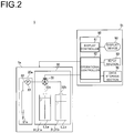
- FIG. 2 is a block diagram of the automated analyzer shown in FIG. 1 .
- the control section 1b includes a display device 50.
- the control section 1b has an input section 60, a data storage section 70, and an input/output controller 80 which will be described in further detail in relation to FIGS. 1 and 2 .
- the measuring section 1a and the control section 1b are described in turn.
- the analyte holding portion 2 is one of storage receptacle holding portions for holding a plurality of storage receptacles in which liquid aliquots are stored.
- This analyte holding portion 2 is shaped, for example, in the form of a turntable.
- Plural rows of analyte receptacles P2 i.e., storage receptacles
- the held analyte receptacles P2 are transported in both directions circumferentially.
- the analyte holding portion 2 is supported so as to be rotatable circumferentially by a drive mechanism (not shown).
- Analytes under measurement and control analytes used for accuracy management are stored as liquid aliquots in the analyte receptacles P2 which in turn are held on the analyte holding portion 2. These various analytes are held in position on the analyte holding portion 2.
- Diluent receptacles storing a diluent and cleaning solution receptacles storing a cleaning solution may be held as storage receptacles on the analyte holding portion 2, as well as the analyte receptacles P2.
- the analyte holding portion 2 described so far may have a function of cooling the held analyte receptacles P2 and other receptacles.
- the analyte disperser 20a is one of the dispensers 20 and has an analyte probe 21a that is a dispensing probe 21 in the form of a thin tube.
- the analyte disperser 20a is disposed close both to the outer peripheries of the analyte holding portion 2 and of the diluted analyte holding portion 3.
- the analyte probe 21a has an open end at one end thereof, and dispenses and aspirates liquid into and from the open end.
- the analyte probe 21a has the other end in communication with the liquid supply tube 22.
- a pump 23 for aspirating and delivering liquid from the open end (one end) of the analyte probe 21a is mounted in the liquid supply tube 22.
- the analyte dispenser 20a inserts the open end of the analyte probe 21a whose axial direction is kept vertical into the analyte in a selected one of the analyte receptacles P2 held on the analyte holding portion 2 by a drive mechanism (not shown) and draws a given amount of analyte into the analyte probe 21a in accordance with a preset measurement program.
- the analyte holding portion 2 transports the analyte receptacles P2 held in position on the analyte holding portion 2 into a given analyte collection position in accordance with the preset measurement program.
- the analyte dispenser 20a inserts the open end of the analyte probe 21a into a selected one of the dilution receptacles P3 on the dilution analyte holding portion 3 and dispenses the analyte aspirated in the analyte probe 21a and the probe internal liquid supplied from the liquid supply tube 22 into the dilution receptacle P3.
- the probe internal liquid is the liquid supplied from the internal liquid supply device 30, to be described hereinafter, and is physiological salt solution, pure water, or other liquid. These liquids are used as a diluent, pretreatment liquid having hemolytic action, or a detergent, as appropriate according to measurement item or details of processing.
- the analyte dispenser 20a carries out cleaning of the internal wall of the analyte probe 21a.
- the analyte dispenser 20a inserts the open end of the analyte probe 21a into the reaction receptacle P6 on the reaction receptacle holding portion 6. Then, the analyte dispenser 20a dispenses the analyte drawn in the analyte probe 21a and the probe internal liquid into the reaction receptacle P6.
- the diluted analyte dispenser 20b is one of the dispensers 20 and equipped with a diluted analyte probe 21b that is a dispensing probe 21 in the form of a thin tube.
- the diluted analyte dispenser 20b is disposed between the diluted analyte holding portion 3 and the reaction receptacle holding portion 6.
- the diluted analyte dispenser 20b causes a drive mechanism (not shown) to insert the open end of the diluted analyte probe 21b having its axial direction kept vertical into a selected one of the dilution receptacles P3 on the diluted analyte holding portion 3 and to draw in a given amount of diluted analyte from the open end of the diluted analyte probe 21b filled with a system water in accordance with a preset measurement program.
- the diluted analyte dispenser 20b inserts the open end of the diluted analyte probe 21b into a selected one of the reaction receptacles P6 on the reaction receptacle holding portion 6 and dispenses the aspirated diluted analyte drawn in the diluted analyte probe 21b into the reaction receptacle P6. Additionally, the diluted analyte dispenser 20b carries out cleaning of the inner wall of the diluted analyte probe 21b. Where the automated analyzer 1 is not equipped with the diluted analyte holding portion 3, the analyzer 1 does not need to have the diluted analyte dispenser 20b.
- the first reagent dispenser 20c is one of the dispensers 20 and equipped with a first reagent probe 21c that is a dispensing probe 21 in the form of a thin tube.
- the first reagent dispenser 20c is disposed between the reaction receptacle holding portion 6 and the first reagent holding portion 4.
- the first reagent dispenser 21c causes a drive mechanism (not shown) to insert the open end of the first reagent probe 21c having its axial direction kept vertical into a selected one of the first reagent receptacles P4 on the first reagent holding portion 4 such that a given amount of the first reagent is aspirated from the open end of the first reagent probe 21c filled with the system water in accordance with a preset measurement program.
- the first reagent dispenser 20c inserts the open end of the first reagent probe 21c into a selected one of the reaction receptacles P6 on the reaction receptacle holding portion 6 and dispenses the first reagent drawn in the first reagent probe 21c into the reaction receptacle P6. Additionally, the first reagent dispenser 20c carries out cleaning of the inner wall of the first reagent probe 21c.
- the second reagent dispenser 20d is one of the dispensers 20 and equipped with the second reagent probe 21d being a dispensing probe 21 in the form of a thin tube, and is disposed between the reaction receptacle holding portion 6 and the second reagent holding portion 5.
- the second reagent dispenser 20d causes a drive mechanism (not shown) to insert the open end of the second reagent probe 21d having its axial direction kept vertical into a selected one of the second reagent receptacles P5 on the second reagent holding portion 5 such that a given amount of the second reagent is aspirated from the open end of the second reagent probe 21d filled with the system water in accordance with a preset measurement program.
- the second reagent dispenser 20d inserts the open end of the second reagent probe 21d into a selected one of the reaction receptacles P6 on the reaction receptacle holding portion 6 and dispenses the second reagent drawn in the second reagent probe 21d into the reaction receptacle P6. Additionally, the second reagent dispenser 20d carries out cleaning of the inner wall of the second reagent probe 21d.
- the internal liquid supply device 30 is intended to supply the probe internal liquid into the analyte probe 21a.
- the internal liquid supply device 30 has a first tank 31a and a second tank 31b (which may be collectively referred to as liquid tanks 31) in which the probe internal liquid L is stored. It is assumed that different probe internal liquids La and Lb corresponding to measurement items are stored in the first tank 31a and the second tank 31b, respectively.
- the internal liquid supply device 30 has supply tubes 32a and 32b which are inserted in the first tank 31a and the second tank 31b, respectively.
- the supply tubes 32a and 32b are connected with the liquid supply tube 22 of the analyte probe 21a to place the liquid tanks 31 into communication with the other end of the analyte probe 21a.
- a selector valve 33 is mounted in front of the supply tubes 32a and 32b to selectively place these supply tubes 32a and 32b into fluid communication with the liquid supply tube 22.
- the selector valve 33 places one of the two supply tubes 32a and 32b into communication with the liquid supply tube 22 and blocks communication from the other to the liquid supply tube 22. Consequently, the analyte probe 21a in communication with the liquid supply tube 22 is connectable with the first tank 31a or the second tank 31b in which a respective one of the two supply tubes 32a and 32b is inserted.
- the internal states of the liquid tanks 31 are switched by the selector valve 33 in this way.
- the selector valve 33 is not restricted to a three-way valve as long as the valve can switch the supply tube 32a or 32b in flow communication with the liquid supply tube 22.
- the selector valve 33 may use plural two-way valves respectively mounted between the liquid supply tube 22 and one supply tube 32a and between the liquid supply tube 22 and the other supply tube 32b by combining the selector valve 33 with a pump added according to the need.
- FIGS. 1 and 2 One example of screen displayed on the display device 50 is next described with reference to FIGS. 1 and 2 and some of FIGS. 3-6
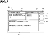
- FIG. 3 is a screen diagram illustrating one example of confirmation screen 51 displayed on the display device 50.
- the confirmation screen 51 for confirmation of the present status of the automated analyzer 1 is presented on the display device 50.
- the confirmation screen 51 contains instrument status 51a, unmeasurable items 51b, measurement progress status 51c, and other data.
- Measurement items that cannot be measured under the current instrument status are displayed as the unmeasurable items 51b.
- measurement items that cannot be measured using the current probe internal liquid of the analyte probe 21a are displayed.
- measurable items may be displayed.
- the status of measurement progress of a requested measurement item is displayed as the measurement progress status 51c.
- warnings are sequentially displayed along the progress of a normal measurement operation.
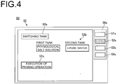
- FIG. 4 illustrates one example of a control screen 52 displayed on the display device 50.
- the control screen 52 for the automated analyzer 1 is displayed.
- This control screen 52 includes, for example, a tank switching button or icon 52a for switching the liquid tank 31 containing the probe internal liquid and connected with the analyte probe 21a, a tank display button or icon 52b, and a priming execution control button or icon 52c.
- this display device 50 is provided with a touch panel, an input is provided for switching the liquid tank 31 connected with the analyte probe 21a by touching the tank switching button 52a.
- Information indicating whether the liquid tank 31 currently connected with the analyte probe 21a is the first tank 31a or the second tank 31b is displayed on the tank display button 52b.
- the probe internal liquid L stored in the liquid tank 31 may also be displayed.
- an input is provided for execution of a priming operation consisting of replacing the probe internal liquid present both in the liquid supply tube 22 and in the analyte probe 21a. This input action may be performed by manipulating a cursor (not shown) by means of the input section 60.
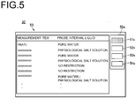
- FIG. 5 illustrates one example of the measurement item setting screen 53 displayed on the display device 50.
- the setting screen 53 for a measurement item or items is displayed on the display device 50.
- the measurement item setting screen 53 includes, for example, information about the measurement item(s) measured by the automated analyzer 1 and information about the probe internal liquid of the analyte probe 21a for carrying out the measurement of the measurement item. It is assumed that such setting is represented by information which is entered, for example, from the input section 60 and stored in the data storage section 70.
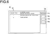
- FIG. 6 illustrates one example of the liquid tank setting screen 54 displayed on the display device 50.
- the liquid tank setting screen 54 is displayed on the display device 50.
- This setting screen 54 includes, for example, a display of the probe internal liquids L stored in the first tank 31a and second tank 31b, respectively, mounted in the automated analyzer 1.
- the settings are such that physiological salt solution is stored in the first tank 31a and that pure water is stored in the second tank 31b. It is assumed that such settings are represented, for example, by information which is entered from the input section 60 and stored in the data storage section 70.
- a choice screen 50s is kept displayed at all times on the display device 50.
- the choice screen 50s includes a plurality of choice buttons or icons 51s-54s. When these choice buttons 51s-54s are touched, the confirmation screen 51, a control screen 52, a measurement item setting screen 53, and a liquid tank setting screen 54 are respectively selected and displayed. Other screens can be displayed on the display device 50.
- the input section 60 accepts inputs regarding various settings made by the operator of the automated analyzer 1, inputs regarding settings of operation of various drive mechanisms, and other inputs, and provides input signals to the input/output controller 80.
- a mouse, a keyboard, a touch panel mounted on the display face of the display device 50, or the like is used as the input section 60.
- this automated analyzer 1 is connected with a personal computer or other external device, such external device may act as the input section 60.
- the data storage section 70 is made, for example, of a mass storage device such as a HDD (hard disk drive) or a semiconductor memory.
- Various programs executed by the input/output controller 80, to be described next, the current status of the aforementioned automated analyzer 1, various setting information, and various operational history information are stored in the data storage section 70.
- the setting information is, for example, related to measurement items, and is information concerning the probe internal liquid of the analyte probe 21a for carrying out measurements of measurement items.
- the setting information is established on the measurement item setting screen 53 shown in FIG. 5 .
- Another type of setting information is related to the liquid tank 31 placed, for example, in communication with the analyte probe 21a.
- a further type of setting information is related to the probe internal liquids L stored in the first tank 31a and in the second tank 32b and established on the liquid tank setting screen 54 shown in FIG. 6 .
- These types of setting information are stored in the data storage section 70 in response to inputs from the input section 60.
- the operational history information is related to measurement history and warning history and displayed, for example, in the measurement progress status 51c shown in FIG. 3 .
- These kinds of history information are stored in the data storage section 70 based on signals from the input/output controller 80.
- the input/output controller 80 is made of a computing device such as a microcomputer.
- the computing device has a CPU (central processing unit) and storage sections such as a ROM (read only memory) and a RAM (random access memory) and controls the operation of the various parts of the automated analyzer 1.
- This input/output controller 80 has a display controller 81 and an operational controller 82.
- the storage sections such as a ROM and a RAM may be the data storage section 70.
- the display controller 81 generates displayed screens based on an input signal from the input section 60, on information stored in the data storage section 70, and on signals from the operation controller 82 and from the measuring section 1a, and displays the generated screens on the display device 50.
- the manner in which the display device 50 is controlled by the display controller 81 is described in detail in relation to the method of automated analysis described next.
- the operation controller 82 controls the operational timings of the drive mechanisms of the measuring section 1a and the timing at which light intensity is measured at the multi-wavelength photometer 15. At this time, the operation controller 82 controls the drive mechanisms of the analyte dispenser 20a and of the internal liquid supply device 30 such that an analyte is aspirated from a given analyte receptacle P2 held on the analyte holding portion 2 and a given probe internal liquid is dispensed together with the analyte into a selected one of the dilution receptacles P3 held on the diluted analyte holding portion 3 by the analyte probe 21a.
- the operation controller 82 controls the drive mechanisms such that the diluted analyte in the dilution receptacle P3, the first reagent in the first reagent receptacle P4, and the second reagent in the second reagent receptacle P5 are mixed and reacted together in the reaction receptacle P6 and that the absorbance of the resulting reaction liquid is measured by the multi-wavelength photometer 15.
- the manner in which measurements are controlled by the operation controller 82 is described in detail next in relation to the method of automated analysis.
- the operation controller 82 switches the operative liquid tank 31 in connection with the liquid supply tube 22 based on an input signal from the input section 60. This switching operation performed by the operation controller 82 is described in detail next with reference to the method of automated analysis.
- step S2 determines whether the measurement is impossible to perform. If control goes to step S101, the operation controller 82 instructs the display controller 81 to produce a warning output to the display device 50.
- the display device 50 provides a warning of infeasibility of the measurement, for example, in the display of the measurement progress status 51c (see FIG. 3 ) of the confirmation screen 51.
- this automated analyzer 1 is equipped with a loudspeaker, a warning light, or the like as a warning output portion
- the operation controller 82 causes such a warning output portion to issue a warning.
- step S103 the operation controller 82 carries out the switching of the operative liquid tank 31. At this time, the operation controller 82 actuates the selector valve 33 of the internal liquid supply device 30 to switch the liquid tank 31 connected with the analyte probe 21a.
- the selector valve 33 for switching the operative liquid tank 31 in communication with the analyte probe 21a is made to operate as an automatic valve.
- an input from the input section 60 can cause the operation controller 82 to actuate the selector valve 33. Therefore, when the operative liquid tank 31 is switched according to requested measurement item, it is not necessary for the operator to manually switch the connection of the liquid tanks 31, thus saving labor.
- the connection of the operative liquid tank 31 were switched manually, human error might take place.
- FIG. 8 is a flowchart illustrating a second example of the method of automated analysis using the automated analyzer 1 of the above embodiment.
- the illustrated method of automated analysis consists of a series of procedures of preprocessing for causing the automated analyzer 1 to initiate measurement processing regarding a requested measurement item when a normal measurement operation is effected.
- the procedures of this second example are similar to the procedures of the first example illustrated in FIG. 7 except that the decision as to whether the operative liquid tank 31 should be switched is made automatically.
- Steps S1-S4 are performed in the same manner as in the first example. However, if the decision at step S2 is NO, indicating that the operation controller 82 has determined that measurement of the requested measurement item with the automated analyzer 1 is not feasible, control goes to step S2a.
- step S2a the operation controller 82 makes a decision as to whether any one of the probe internal liquids L of the first tank 31a and the second tank 31b is coincident with the probe internal liquid of the analyte probe 21a for execution of measurement of the requested measurement item, based on the requested measurement item, on the setting information (see FIG. 5 ) regarding measurement items stored in the data storage section 70, and on the information ( FIG. 6 ) about the liquid tank 31 connected with the analyte probe 21a.
- step S106a the operation controller 82 makes a decision as to whether an exchange of the liquid tank 31 has been performed. If an input indicating that an exchange of the liquid tank 31 has been done is made from the input section 60, the operation controller 82 determines that the exchange has been done (YES), and control goes back to step S2a. The subsequent steps are repeated. On the other hand, if any input indicating that an exchange of the liquid tank 31 has been done is not made from the input section 60 and, at the same time, if an input for canceling measurement of the requested measurement item has been made, for example, the operation controller 82 goes to step S4. The subsequent steps are carried out. Consequently, measurement of the requested measurement item is skipped.
Landscapes
- Physics & Mathematics (AREA)
- Health & Medical Sciences (AREA)
- Life Sciences & Earth Sciences (AREA)
- Chemical & Material Sciences (AREA)
- Analytical Chemistry (AREA)
- Biochemistry (AREA)
- General Health & Medical Sciences (AREA)
- General Physics & Mathematics (AREA)
- Immunology (AREA)
- Pathology (AREA)
- Automatic Analysis And Handling Materials Therefor (AREA)
Abstract
Description
- The present invention relates to an apparatus and method for automated analysis.
- Biochemical analyzers for analyzing biochemical components contained in an analyte such as blood or urine are known as one type of automated analyzer. Such an automated analyzer is disclosed (see Patent document 1) and configured, when a given amount of a sample is aspirated by a sample dispensing probe and then dispensed into a reaction cell, to perform the function of dispensing a liquid, which performs a hemolytic action in the sample dispensing probe, into the reaction cell together with the sample.
- Patent document 1:
JP-A-2012-108062 - The automated analyzer described so far can perform measurements about different items of measurement by replacing the liquid (such as a liquid having hemolytic action) present inside the sample dispensing probe by other liquids such as physiological salt solution. However, in order to replace the internal liquid of the sample dispensing probe, it is necessary to switch the liquid tank connected with the sample dispensing probe to a different liquid tank, thus taking labor.
- Accordingly, it is an object of the present invention to provide an apparatus and method for automated analysis in which plural liquid tanks are connected with a dispensing probe such that only one of the tanks (hereinafter may also be referred to as the operative tank) in fluid communication with the dispensing probe and functioning can be effectively switched according to measurement item.
- This object is achieved in accordance with the teachings of the present invention by an automated analyzer comprising:
- a liquid dispenser having a dispensing probe and a pump capable of aspirating and dispensing a liquid from and into an open end of the dispensing probe that is at one end thereof, the liquid dispenser being operative to cause the liquid aspirated in the dispensing probe from the open end and a probe internal liquid of the dispensing probe to be dispensed into aliquot receptacles;
- an internal liquid supply device having a plurality of liquid tanks in which probe internal liquids corresponding to measurement items are stored, supply tubes for placing the liquid tanks in communication with the other end of the dispensing probe, and a selector valve mounted in front of the supply tubes and operative to selectively placing the plurality of liquid tanks into communication with the dispensing probe, the internal liquid supply device being operative to supply a probe internal liquid into the dispensing probe from one of the liquid tanks;
- an input section for entering settings regarding operation of the dispenser; and
- an operation controller for controlling operation of the dispenser based on inputs from the input section.
- The automated analyzer performs measurements regarding different measurement items by switching the liquid tank in communication with the dispensing probe via the selector valve, which is an automatic valve, under control of the operation controller.
- The present invention can provide an apparatus and method for automated analysis capable of efficiently switching, according to measurement item, the liquid tank in fluid communication with the dispensing probe between the plurality of liquid tanks connected with the dispensing probe.
-
-
FIG. 1 is a schematic perspective view of an automated analyzer associated with one embodiment of the present invention. -
FIG. 2 is a block diagram of the automated analyzer ofFIG. 1 . -
FIG. 3 is a screen diagram illustrating one example of confirmation screen displayed on the display device. -
FIG. 4 is a screen diagram illustrating one example of control screen displayed on the display device. -
FIG. 5 is a screen diagram illustrating one example of setting screen for measurement items displayed on the display device. -
FIG. 6 is a screen diagram illustrating one example of liquid tank setting screen displayed on the display device. -
FIG. 7 is a flowchart illustrating a first example of the method of automated analysis using the automated analyzer ofFIG. 1 . -
FIG. 8 is a flowchart illustrating a second example of the method of automated analysis using the automated analyzer ofFIG. 1 . - Embodiments of the apparatus and method for automated analysis of the present invention are hereinafter described in detail with reference to the drawings.
-
FIG. 1 schematically shows the configuration of an automated analyzer associated with one embodiment of the present invention. This automated analyzer, 1, according to the present invention is a biochemical analyzer for analyzing biological components contained in each analyte such as blood or urine. As shown inFIG. 1 , theautomated analyzer 1 has ameasuring section 1a and acontrol section 1b. - The
measuring section 1a includes, for example, ananalyte holding portion 2, a diluted analyte holding portion 3, a first reagent holding portion 4, a secondreagent holding portion 5, and a reaction receptacle holding portion 6. Furthermore, themeasuring section 1a includes adiluent stirrer 11, adilution cleaning device 12, a first reaction stirrer 13, a second reaction stirrer 14, amulti-wavelength photometer 15, and reactionreceptacle cleaning devices 16. - In addition, the
measuring section 1a has a plurality of dispensers 20 and an internalliquid supply device 30. In this example, the dispensers 20 are four in number, i.e., ananalyte dispenser 20a, a diluted analyte dispenser 20b, a first reagent dispenser 20c, and a second reagent dispenser 20d. Each dispenser 20 has a dispensing probe 21. -
FIG. 2 is a block diagram of the automated analyzer shown inFIG. 1 . As shown, thecontrol section 1b includes adisplay device 50. Furthermore, thecontrol section 1b has aninput section 60, adata storage section 70, and an input/output controller 80 which will be described in further detail in relation toFIGS. 1 and2 . First, themeasuring section 1a and thecontrol section 1b are described in turn. - The
analyte holding portion 2 is one of storage receptacle holding portions for holding a plurality of storage receptacles in which liquid aliquots are stored. Thisanalyte holding portion 2 is shaped, for example, in the form of a turntable. Plural rows of analyte receptacles P2 (i.e., storage receptacles) are held along the fringes of theanalyte holding portion 2. The held analyte receptacles P2 are transported in both directions circumferentially. Theanalyte holding portion 2 is supported so as to be rotatable circumferentially by a drive mechanism (not shown). Analytes under measurement and control analytes used for accuracy management are stored as liquid aliquots in the analyte receptacles P2 which in turn are held on theanalyte holding portion 2. These various analytes are held in position on theanalyte holding portion 2. - Diluent receptacles storing a diluent and cleaning solution receptacles storing a cleaning solution may be held as storage receptacles on the
analyte holding portion 2, as well as the analyte receptacles P2. Theanalyte holding portion 2 described so far may have a function of cooling the held analyte receptacles P2 and other receptacles. - The diluted analyte holding portion 3 is one of aliquot receptacle holding portions for holding aliquot receptacles that are target receptacles for dispensed liquid aliquots, and is also one of the storage receptacle holding portions for holding a plurality of storage receptacles in which liquid aliquots are stored. This diluted analyte holding portion is in the form, for example, of a turntable and holds a plurality of dilution receptacles P3 (i.e., serving as aliquot receptacles and also as storage receptacles) along its fringes. The diluted analyte holding portion conveys the held dilution receptacles P3 in both directions circumferentially. The diluted analyte holding portion 3 is supported by a drive mechanism (not shown) so as to be rotatable circumferentially.
- Analytes aspirated from the analyte receptacles P2 arranged on the
analyte holding portion 2 are diluted and dispensed as liquid aliquots into the dilution receptacles P3 that are held on the diluted analyte holding portion 3. The diluted analytes are stored as liquid aliquots in the analyte receptacles P2. Theautomated analyzer 1 may not be provided with the diluted analyte holding portion 3. - Each of the first reagent holding portion 4 and the second
reagent holding portion 5 is one of the storage receptacle holding portions for holding a plurality of storage receptacles in which liquid aliquots are stored. The first reagent holding portion 4 is in the form, for example, of a turntable and holds along its fringes a plurality of first reagent receptacles P4 (i.e., storage receptacles). Similarly, the secondreagent holding portion 5 is in the form, for instance, of a turntable and holds along its fringes a plurality of second reagent receptacles P5 (i.e., storage receptacles). The first reagent holding portion 4 and the secondreagent holding portion 5 convey the held first reagent receptacles P4 and second reagent receptacles P5, respectively, in both directions circumferentially. These first and secondreagent holding portions 4 and 5 are supported by their respective drive mechanisms (not shown) so as to be rotatable circumferentially. - The reaction receptacle holding portion 6 is one of the aliquot receptacle holding portions for holding aliquot receptacles that will be aliquot targets for liquid aliquots. This reaction receptacle holding portion 6 is arranged among the diluted analyte holding portion 3, the first reagent holding portion 4, and the second
reagent holding portion 5. This reaction receptacle holding portion 6 is, for example, in the form of a turntable, holds along its fringes a plurality of reaction receptacles P6 (i.e., aliquot receptacles), and conveys the held reaction receptacles P6 in both directions circumferentially. The reaction receptacle holding portion 6 is supported by a drive mechanism (not shown) so as to be rotatable circumferentially. - A given amount of the diluted analyte collected from a selected one of the dilution receptacles P3 on the diluted analyte holding portion 3, a given amount of the first reagent collected from a selected one of the first reagent receptacles P4 on the first reagent holding portion 4, and a given amount of the second reagent collected from a selected one of the second reagent receptacles P5 on the second
reagent holding portion 5 are dispensed as aliquots into each reaction receptacle P6 held on the reaction receptacle holding portion 6. In the reaction receptacle P6, the diluted analyte, first reagent, and second reagent are stirred and reacted together. Alternatively, the diluted analyte and the first reagent may be stirred and reacted together. - The reaction receptacle holding portion 6 as described so far is configured to maintain the temperature of the reaction receptacles P6 constant at all times by a thermostat bath (not shown). Where the
automated analyzer 1 is not provided with the diluted analyte holding portion 3, analytes collected from the analyte receptacles P2 on theanalyte holding portion 2 are dispensed as aliquots into the reaction receptacles P6 held on the reaction receptacle holding portion 6. - The
diluent stirrer 11 is disposed near the outer periphery of the diluted analyte holding portion 3. Thediluent stirrer 11 has a stirring mechanism and a drive mechanism for driving the stirring mechanism. Thediluent stirrer 11 inserts a stirring element (not shown) into a selected one of the dilution receptacles P3 held on the dilution holding portion 3 and stirs together an analyte and a diluent. - The
dilution cleaning device 12 is disposed near the outer periphery of the diluted analyte holding portion 3. Thedilution cleaning device 12 is a device for cleaning the dilution receptacles P3 from which the diluted analyte has been aspirated by the diluted analyte dispenser 20b, to be described hereinafter. - The
first reaction stirrer 13 and thesecond reaction stirrer 14 are arranged around the reaction receptacle holding portion 6 and stir together the diluted analyte and the first reagent or the second reagent, respectively, in the reaction receptacles P6 held on the reaction receptacle holding portion 6. Each of thefirst reaction stirrer 13 and thesecond reaction stirrer 14 has a stirring mechanism and a drive mechanism for driving the stirring mechanism, inserts a stirring element (not shown) into the reaction receptacle P6 held in position on the reaction receptacle holding portion 6, and stirs together the diluted analyte (or analyte) and the first reagent or second reagent. Consequently, the reaction of the diluted analyte with the first reagent or the second reagent is promoted. - The
multi-wavelength photometer 15 is a measuring section and disposed opposite to the outer peripheral wall of the reaction receptacle holding portion 6. Themulti-wavelength photometer 15 performs optical measurements on diluted analytes which have reacted with the first or second reagent in the reaction receptacles P6, outputs signals indicative of the amounts of various components in the analytes as absorbances, and detects the state of reaction of the diluted analytes. - The reaction
receptacle cleaning devices 16 are arranged around the reaction receptacle holding portion 6. Thecleaning devices 16 are devices for cleaning the insides of the reaction receptacles P6 for which testing has been completed. - The
analyte disperser 20a is one of the dispensers 20 and has ananalyte probe 21a that is a dispensing probe 21 in the form of a thin tube. Theanalyte disperser 20a is disposed close both to the outer peripheries of theanalyte holding portion 2 and of the diluted analyte holding portion 3. Theanalyte probe 21a has an open end at one end thereof, and dispenses and aspirates liquid into and from the open end. Theanalyte probe 21a has the other end in communication with theliquid supply tube 22. Apump 23 for aspirating and delivering liquid from the open end (one end) of theanalyte probe 21a is mounted in theliquid supply tube 22. - The
analyte dispenser 20a inserts the open end of theanalyte probe 21a whose axial direction is kept vertical into the analyte in a selected one of the analyte receptacles P2 held on theanalyte holding portion 2 by a drive mechanism (not shown) and draws a given amount of analyte into theanalyte probe 21a in accordance with a preset measurement program. At this time, theanalyte holding portion 2 transports the analyte receptacles P2 held in position on theanalyte holding portion 2 into a given analyte collection position in accordance with the preset measurement program. - Furthermore, the
analyte dispenser 20a inserts the open end of theanalyte probe 21a into a selected one of the dilution receptacles P3 on the dilution analyte holding portion 3 and dispenses the analyte aspirated in theanalyte probe 21a and the probe internal liquid supplied from theliquid supply tube 22 into the dilution receptacle P3. The probe internal liquid is the liquid supplied from the internalliquid supply device 30, to be described hereinafter, and is physiological salt solution, pure water, or other liquid. These liquids are used as a diluent, pretreatment liquid having hemolytic action, or a detergent, as appropriate according to measurement item or details of processing. Furthermore, theanalyte dispenser 20a carries out cleaning of the internal wall of theanalyte probe 21a. - Where the
automated analyzer 1 is not provided with the diluted analyte holding portion 3, theanalyte dispenser 20a inserts the open end of theanalyte probe 21a into the reaction receptacle P6 on the reaction receptacle holding portion 6. Then, theanalyte dispenser 20a dispenses the analyte drawn in theanalyte probe 21a and the probe internal liquid into the reaction receptacle P6. - The diluted analyte dispenser 20b is one of the dispensers 20 and equipped with a diluted analyte probe 21b that is a dispensing probe 21 in the form of a thin tube. The diluted analyte dispenser 20b is disposed between the diluted analyte holding portion 3 and the reaction receptacle holding portion 6. The diluted analyte dispenser 20b causes a drive mechanism (not shown) to insert the open end of the diluted analyte probe 21b having its axial direction kept vertical into a selected one of the dilution receptacles P3 on the diluted analyte holding portion 3 and to draw in a given amount of diluted analyte from the open end of the diluted analyte probe 21b filled with a system water in accordance with a preset measurement program. Furthermore, the diluted analyte dispenser 20b inserts the open end of the diluted analyte probe 21b into a selected one of the reaction receptacles P6 on the reaction receptacle holding portion 6 and dispenses the aspirated diluted analyte drawn in the diluted analyte probe 21b into the reaction receptacle P6. Additionally, the diluted analyte dispenser 20b carries out cleaning of the inner wall of the diluted analyte probe 21b. Where the
automated analyzer 1 is not equipped with the diluted analyte holding portion 3, theanalyzer 1 does not need to have the diluted analyte dispenser 20b. - The first reagent dispenser 20c is one of the dispensers 20 and equipped with a first reagent probe 21c that is a dispensing probe 21 in the form of a thin tube. The first reagent dispenser 20c is disposed between the reaction receptacle holding portion 6 and the first reagent holding portion 4. The first reagent dispenser 21c causes a drive mechanism (not shown) to insert the open end of the first reagent probe 21c having its axial direction kept vertical into a selected one of the first reagent receptacles P4 on the first reagent holding portion 4 such that a given amount of the first reagent is aspirated from the open end of the first reagent probe 21c filled with the system water in accordance with a preset measurement program. Furthermore, the first reagent dispenser 20c inserts the open end of the first reagent probe 21c into a selected one of the reaction receptacles P6 on the reaction receptacle holding portion 6 and dispenses the first reagent drawn in the first reagent probe 21c into the reaction receptacle P6. Additionally, the first reagent dispenser 20c carries out cleaning of the inner wall of the first reagent probe 21c.
- The second reagent dispenser 20d is one of the dispensers 20 and equipped with the second reagent probe 21d being a dispensing probe 21 in the form of a thin tube, and is disposed between the reaction receptacle holding portion 6 and the second
reagent holding portion 5. The second reagent dispenser 20d causes a drive mechanism (not shown) to insert the open end of the second reagent probe 21d having its axial direction kept vertical into a selected one of the second reagent receptacles P5 on the secondreagent holding portion 5 such that a given amount of the second reagent is aspirated from the open end of the second reagent probe 21d filled with the system water in accordance with a preset measurement program. Furthermore, the second reagent dispenser 20d inserts the open end of the second reagent probe 21d into a selected one of the reaction receptacles P6 on the reaction receptacle holding portion 6 and dispenses the second reagent drawn in the second reagent probe 21d into the reaction receptacle P6. Additionally, the second reagent dispenser 20d carries out cleaning of the inner wall of the second reagent probe 21d. - The internal
liquid supply device 30 is intended to supply the probe internal liquid into theanalyte probe 21a. The internalliquid supply device 30 has a first tank 31a and a second tank 31b (which may be collectively referred to as liquid tanks 31) in which the probe internal liquid L is stored. It is assumed that different probe internal liquids La and Lb corresponding to measurement items are stored in the first tank 31a and the second tank 31b, respectively. Furthermore, the internalliquid supply device 30 hassupply tubes supply tubes liquid supply tube 22 of theanalyte probe 21a to place the liquid tanks 31 into communication with the other end of theanalyte probe 21a. - A
selector valve 33 is mounted in front of thesupply tubes supply tubes liquid supply tube 22. In particular, theselector valve 33 places one of the twosupply tubes liquid supply tube 22 and blocks communication from the other to theliquid supply tube 22. Consequently, theanalyte probe 21a in communication with theliquid supply tube 22 is connectable with the first tank 31a or the second tank 31b in which a respective one of the twosupply tubes selector valve 33 in this way. As a result, the probe internal liquids La and Lb stored in the first tank 31a and the second tank 31b, respectively, can selectively work as the probe internal liquid present both in theliquid supply tube 22 and in theanalyte probe 21a. As an example, a three-way valve is used as theselector valve 33. - Furthermore, this
selector valve 33 can be a motor-operated valve (such as an electromagnetic valve) that can selectively establish and break the aforementioned fluid communication under instructions from thecontrol section 1b, to be described next. - The
selector valve 33 is not restricted to a three-way valve as long as the valve can switch thesupply tube liquid supply tube 22. For example, theselector valve 33 may use plural two-way valves respectively mounted between theliquid supply tube 22 and onesupply tube 32a and between theliquid supply tube 22 and theother supply tube 32b by combining theselector valve 33 with a pump added according to the need. - The
control section 1b is connected with drive mechanisms for various components of the above-describedmeasuring section 1a and with themulti-wavelength photometer 15. Thiscontrol section 1b has thedisplay device 50, theinput section 60, thedata storage section 70, and the input/output controller 80, to be described in detail as follows. - The
display device 50 displays the results of measurements performed by themulti-wavelength photometer 15. In addition, thedisplay device 50 displays a control screen permitting an operator to control and manipulate theautomated analyzer 1, various setting information about measurements, and various operational history information. It is also assumed that thedisplay device 50 acts also as an alarm output portion which produces an alarm output when an abnormality occurs with a measurement operation performed by theautomated analyzer 1 or when a measurement item asked to be measured cannot be measured under the current state of operation of the automated analyzer. The warning output portion is not restricted to thedisplay device 50. The warning output portion may be a loudspeaker (not shown) or a combination of thedisplay device 50 and a loudspeaker. - One example of screen displayed on the
display device 50 is next described with reference toFIGS. 1 and2 and some ofFIGS. 3-6 -
FIG. 3 is a screen diagram illustrating one example ofconfirmation screen 51 displayed on thedisplay device 50. As shown inFIG. 3 , theconfirmation screen 51 for confirmation of the present status of theautomated analyzer 1 is presented on thedisplay device 50. Theconfirmation screen 51 containsinstrument status 51a,unmeasurable items 51b,measurement progress status 51c, and other data. - Among these data, the probe internal liquid of the
analyte probe 21a and reagents stored in the storage receptacles on the first reagent holding portion 4 and secondreagent holding portion 5, for example, are displayed as theinstrument status 51a. The probe internal liquid of theanalyte probe 21a is information associated with the information about the liquid tank 31 with which theanalyte probe 21a is currently connected, and indicates how the two liquid tanks 31 are in communication with theanalyte probe 21a. - Measurement items that cannot be measured under the current instrument status are displayed as the
unmeasurable items 51b. For example, measurement items that cannot be measured using the current probe internal liquid of theanalyte probe 21a are displayed. Instead of theunmeasurable items 51b, measurable items may be displayed. - The status of measurement progress of a requested measurement item is displayed as the
measurement progress status 51c. When the requested measurement item cannot be measured, warnings are sequentially displayed along the progress of a normal measurement operation. -
FIG. 4 illustrates one example of acontrol screen 52 displayed on thedisplay device 50. As shown in this figure, thecontrol screen 52 for theautomated analyzer 1 is displayed. Thiscontrol screen 52 includes, for example, a tank switching button oricon 52a for switching the liquid tank 31 containing the probe internal liquid and connected with theanalyte probe 21a, a tank display button oricon 52b, and a priming execution control button oricon 52c. - If this
display device 50 is provided with a touch panel, an input is provided for switching the liquid tank 31 connected with theanalyte probe 21a by touching thetank switching button 52a. Information indicating whether the liquid tank 31 currently connected with theanalyte probe 21a is the first tank 31a or the second tank 31b is displayed on thetank display button 52b. The probe internal liquid L stored in the liquid tank 31 may also be displayed. By touching the primingexecution control button 52c, an input is provided for execution of a priming operation consisting of replacing the probe internal liquid present both in theliquid supply tube 22 and in theanalyte probe 21a. This input action may be performed by manipulating a cursor (not shown) by means of theinput section 60. -
FIG. 5 illustrates one example of the measurementitem setting screen 53 displayed on thedisplay device 50. As shown in this figure, thesetting screen 53 for a measurement item or items is displayed on thedisplay device 50. The measurementitem setting screen 53 includes, for example, information about the measurement item(s) measured by theautomated analyzer 1 and information about the probe internal liquid of theanalyte probe 21a for carrying out the measurement of the measurement item. It is assumed that such setting is represented by information which is entered, for example, from theinput section 60 and stored in thedata storage section 70. -
FIG. 6 illustrates one example of the liquidtank setting screen 54 displayed on thedisplay device 50. As shown in this figure, the liquidtank setting screen 54 is displayed on thedisplay device 50. Thissetting screen 54 includes, for example, a display of the probe internal liquids L stored in the first tank 31a and second tank 31b, respectively, mounted in theautomated analyzer 1. In the illustrated example, the settings are such that physiological salt solution is stored in the first tank 31a and that pure water is stored in the second tank 31b. It is assumed that such settings are represented, for example, by information which is entered from theinput section 60 and stored in thedata storage section 70. - Furthermore, as shown in
FIGS. 3-6 , achoice screen 50s is kept displayed at all times on thedisplay device 50. Thechoice screen 50s includes a plurality of choice buttons oricons 51s-54s. When thesechoice buttons 51s-54s are touched, theconfirmation screen 51, acontrol screen 52, a measurementitem setting screen 53, and a liquidtank setting screen 54 are respectively selected and displayed. Other screens can be displayed on thedisplay device 50. - The
input section 60 accepts inputs regarding various settings made by the operator of theautomated analyzer 1, inputs regarding settings of operation of various drive mechanisms, and other inputs, and provides input signals to the input/output controller 80. For example, a mouse, a keyboard, a touch panel mounted on the display face of thedisplay device 50, or the like is used as theinput section 60. Where thisautomated analyzer 1 is connected with a personal computer or other external device, such external device may act as theinput section 60. - The
data storage section 70 is made, for example, of a mass storage device such as a HDD (hard disk drive) or a semiconductor memory. Various programs executed by the input/output controller 80, to be described next, the current status of the aforementionedautomated analyzer 1, various setting information, and various operational history information are stored in thedata storage section 70. - Among these kinds of information, the setting information is, for example, related to measurement items, and is information concerning the probe internal liquid of the
analyte probe 21a for carrying out measurements of measurement items. The setting information is established on the measurementitem setting screen 53 shown inFIG. 5 . Another type of setting information is related to the liquid tank 31 placed, for example, in communication with theanalyte probe 21a. A further type of setting information is related to the probe internal liquids L stored in the first tank 31a and in thesecond tank 32b and established on the liquidtank setting screen 54 shown inFIG. 6 . These types of setting information are stored in thedata storage section 70 in response to inputs from theinput section 60. - The operational history information is related to measurement history and warning history and displayed, for example, in the
measurement progress status 51c shown inFIG. 3 . These kinds of history information are stored in thedata storage section 70 based on signals from the input/output controller 80. - The input/
output controller 80 is made of a computing device such as a microcomputer. The computing device has a CPU (central processing unit) and storage sections such as a ROM (read only memory) and a RAM (random access memory) and controls the operation of the various parts of theautomated analyzer 1. This input/output controller 80 has adisplay controller 81 and anoperational controller 82. The storage sections such as a ROM and a RAM may be thedata storage section 70. - The
display controller 81 generates displayed screens based on an input signal from theinput section 60, on information stored in thedata storage section 70, and on signals from theoperation controller 82 and from the measuringsection 1a, and displays the generated screens on thedisplay device 50. The manner in which thedisplay device 50 is controlled by thedisplay controller 81 is described in detail in relation to the method of automated analysis described next. - The
operation controller 82 controls the operational timings of the drive mechanisms of the measuringsection 1a and the timing at which light intensity is measured at themulti-wavelength photometer 15. At this time, theoperation controller 82 controls the drive mechanisms of theanalyte dispenser 20a and of the internalliquid supply device 30 such that an analyte is aspirated from a given analyte receptacle P2 held on theanalyte holding portion 2 and a given probe internal liquid is dispensed together with the analyte into a selected one of the dilution receptacles P3 held on the diluted analyte holding portion 3 by theanalyte probe 21a. - Furthermore, the
operation controller 82 controls the drive mechanisms such that the diluted analyte in the dilution receptacle P3, the first reagent in the first reagent receptacle P4, and the second reagent in the second reagent receptacle P5 are mixed and reacted together in the reaction receptacle P6 and that the absorbance of the resulting reaction liquid is measured by themulti-wavelength photometer 15. The manner in which measurements are controlled by theoperation controller 82 is described in detail next in relation to the method of automated analysis. - The
operation controller 82 switches the operative liquid tank 31 in connection with theliquid supply tube 22 based on an input signal from theinput section 60. This switching operation performed by theoperation controller 82 is described in detail next with reference to the method of automated analysis. -
FIG. 7 is a flowchart illustrating a first example of the method of automated analysis using the automatedanalyzer 1 of the above-described embodiment. The illustrated method of automated analysis consists of a series of procedures of preprocessing for causing theautomated analyzer 1 to initiate measurement processing regarding a requested measurement item when a normal measurement operation is affected. - This series of procedures is accomplished by executing programs stored in the data storage section by the use of the CPU constituting the input/
output controller 80 already described in connection withFIG. 2 . The first example of the method of automated analysis performed by the input/output controller 80 of theautomated analyzer 1 is described below by referring to the flowchart ofFIG. 7 and also toFIGS. 1 and2 and further toFIGS. 3-6 as necessary. - First, at step S1, the
operation controller 82 makes a decision as to whether there is a request for measurement from theinput section 60. This decision is repeatedly carried out until a Yes decision (i.e., there is a request for measurement) occurs, in which case control goes to step S2. - In step S2, the
operation controller 82 makes a decision as to whether theautomated analyzer 1 can make a measurement regarding the requested measurement item, based on the setting information (seeFIG. 5 ) about the measurement item stored in thedata storage section 70 and on the current status of the automated analyzer 1 (seeFIG. 3 ). For example, where the requested measurement item is hemoglobin A1c (HbAlc), if the probe internal liquid L of the liquid tank L31 currently in communication with theanalyte probe 21a is pure water, the decision is YES, i.e., the measurement is feasible. Control proceeds to step S3. On the other hand, if the probe internal liquid L of the liquid tank L31 currently in communication with theanalyte probe 21a is not pure water, the decision is NO, i.e., the measurement is infeasible, and control goes to step S101. - If there is a request for measurement regarding plural measurement items, this decision is carried out for the measurement item to be measured first out of the requested measurement items.
- In step S3, the
operation controller 82 initiates a measurement of the requested measurement item. At this time, if there is a request for plural measurements about the same measurement item, theoperation controller 82 initiates the series of measurements. Then, control proceeds to step S4. - In step S4, the
operation controller 82 makes a decision as to whether or not the normal measurement operation is complete. At this time, if an input is made, for example, from theinput section 60 to terminate the measurement operation performed by theautomated analyzer 1 or if theautomated analyzer 1 is powered off, theoperation controller 82 determines that the measurement operation has ended (YES); otherwise, thecontroller 82 determines that the measurement operation has not ended (NO), and control returns to step S1. A decision is made as to whether or not there is a request for other measurement item, and subsequent steps are performed repeatedly. - On the other hand, if the decision at step S2 is NO, indicating that the measurement is impossible to perform, and if control goes to step S101, the
operation controller 82 instructs thedisplay controller 81 to produce a warning output to thedisplay device 50. In response, thedisplay device 50 provides a warning of infeasibility of the measurement, for example, in the display of themeasurement progress status 51c (seeFIG. 3 ) of theconfirmation screen 51. Where thisautomated analyzer 1 is equipped with a loudspeaker, a warning light, or the like as a warning output portion, theoperation controller 82 causes such a warning output portion to issue a warning. - In consequence, the operator of the
automated analyzer 1 can recognize that the requested measurement item is impossible to measure. Also, the operator confirms that the probe internal liquid of theanalyte probe 21a is not appropriate owing to the display provided on thedisplay device 50. Then, the operator can make an input to switch the operative liquid tank 31, for example, by manipulating the tank switching button oricon 52a (seeFIG. 4 ) in thecontrol screen 52 through theinput section 60. - In step S102, the
operation controller 82 makes a decision as to whether there is an input to switch the operative liquid tank 31. If the tank switching button oricon 52a (seeFIG. 4 ) in thecontrol screen 52 is touched or manipulated, theoperation controller 82 determines that there is an input to switch the operative liquid tank 31 (YES), and control goes to the next step S103. On the other hand, if the tank switching button oricon 52a in thecontrol screen 52 is not manipulated and, at the same time, if an input is made to cancel the measurement of the requested measurement item, for example, theoperation controller 82 goes to step S4. Consequently, the measurement of the requested measurement item is not carried out but skipped. - In step S103, the
operation controller 82 carries out the switching of the operative liquid tank 31. At this time, theoperation controller 82 actuates theselector valve 33 of the internalliquid supply device 30 to switch the liquid tank 31 connected with theanalyte probe 21a. - In step S104, the
operation controller 82 performs a priming process. At this time, theoperation controller 82 controls the operation of thepump 23 mounted in theliquid supply tube 22 of theanalyte probe 21a to replace the probe internal liquid present both in theliquid supply tube 22 and in theanalyte probe 21a with the probe internal liquid L in the liquid tank 31 connected with theanalyte probe 21a, so that the probe internal liquid L acts as a new probe internal liquid. Then, control goes to step S3. Theoperation controller 82 is made to initiate a measurement of the requested measurement item. - According to the first example of the embodiment described so far, the
selector valve 33 for switching the operative liquid tank 31 in communication with theanalyte probe 21a is made to operate as an automatic valve. Thus, an input from theinput section 60 can cause theoperation controller 82 to actuate theselector valve 33. Therefore, when the operative liquid tank 31 is switched according to requested measurement item, it is not necessary for the operator to manually switch the connection of the liquid tanks 31, thus saving labor. As a result, when plural measurement items are measured using different kinds of probe internal liquid of theanalyte probe 21a used for the measurements, if the connection of the operative liquid tank 31 were switched manually, human error might take place. Hence, erroneous connection of the operative tank 31 with theanalyte probe 21a can be prevented. Wasteful measurements using a probe internal liquid inappropriate for the measurement item can be prevented from being carried out. Consequently, measurements using the automatedanalyzer 1 can be enhanced in efficiency. -
FIG. 8 is a flowchart illustrating a second example of the method of automated analysis using the automatedanalyzer 1 of the above embodiment. The illustrated method of automated analysis consists of a series of procedures of preprocessing for causing theautomated analyzer 1 to initiate measurement processing regarding a requested measurement item when a normal measurement operation is effected. The procedures of this second example are similar to the procedures of the first example illustrated inFIG. 7 except that the decision as to whether the operative liquid tank 31 should be switched is made automatically. - These procedures are accomplished by executing programs stored in the data storage section using the CPU constituting the input/
output controller 80 described in relation toFIG. 2 . The second example of the method of automated analysis implemented by the input/output controller 80 of theautomated analyzer 1 is described hereinafter with reference to the flowchart ofFIG. 8 ,FIGS. 1 and2 , and alsoFIGS. 3-6 as necessary. - Steps S1-S4 are performed in the same manner as in the first example. However, if the decision at step S2 is NO, indicating that the
operation controller 82 has determined that measurement of the requested measurement item with theautomated analyzer 1 is not feasible, control goes to step S2a. - In step S2a, the
operation controller 82 makes a decision as to whether any one of the probe internal liquids L of the first tank 31a and the second tank 31b is coincident with the probe internal liquid of theanalyte probe 21a for execution of measurement of the requested measurement item, based on the requested measurement item, on the setting information (seeFIG. 5 ) regarding measurement items stored in thedata storage section 70, and on the information (FIG. 6 ) about the liquid tank 31 connected with theanalyte probe 21a. - If the decision is YES, indicating that there is a probe internal liquid coincident with that of the
analyte probe 21a, control goes to step S103. On the other hand, if the decision is NO, indicating that there is not any probe internal liquid coincident with that of theanalyte probe 21a, control proceeds to step S105a. - Steps S103-S104 are performed in the same way as in the first example. Then, control goes to step S3.
- On the other hand, in step S105a, the
operation controller 82 instructs thedisplay controller 81 to produce a warning output indicative of display to thedisplay device 50. In response, thedisplay device 50 provides a warning of infeasibility of measurement, for example, in the display of themeasurement progress status 51c (seeFIG. 3 ) of theconfirmation screen 51. If theautomated analyzer 1 is equipped with a loudspeaker, a warning light, or the like as a warning output portion, theoperation controller 82 causes the warning output portion to issue a warning. Then, control goes to step S106a. - By executing this step S105a, the operator of the
automated analyzer 1 can recognize that measurement of the requested measurement item is infeasible. Then, the operator confirms that a probe internal liquid permitting measurement of the requested measurement item is stored neither in the first tank 31a nor in the second tank 31b. The liquid tank 31 can be replaced with other tank compliant with the requested measurement item. The measurement item for which a decision has been made at step S2a may not be measured and kept intact. - In step S106a, the
operation controller 82 makes a decision as to whether an exchange of the liquid tank 31 has been performed. If an input indicating that an exchange of the liquid tank 31 has been done is made from theinput section 60, theoperation controller 82 determines that the exchange has been done (YES), and control goes back to step S2a. The subsequent steps are repeated. On the other hand, if any input indicating that an exchange of the liquid tank 31 has been done is not made from theinput section 60 and, at the same time, if an input for canceling measurement of the requested measurement item has been made, for example, theoperation controller 82 goes to step S4. The subsequent steps are carried out. Consequently, measurement of the requested measurement item is skipped. - According to the second example of the embodiment described so far, when measurement of a requested measurement item is made feasible by switching the operative liquid tank 31 in communication with the
analyte probe 21a, the state of theselector valve 33 is automatically switched by theoperation controller 82. As a consequence, it is not necessary to manually switch the liquid tank 31 in communication with theanalyte probe 21a, thus saving labor. Also, erroneous connection of the liquid tanks 31 with theanalyte probe 21a can be prevented. Wasteful measurements using a probe internal liquid unsuitable for the measurement item can be prevented from being carried out. As a result, measurements using the automatedanalyzer 1 can be enhanced in efficiency. - In the description of the embodiment including the first and second examples described so far, the internal
liquid supply device 30 is mounted to supply a probe internal liquid into theanalyte dispensing probe 21a. Note that the present invention can be applied with similar utility, without being restricted to the use of theanalyte dispensing probe 21a, to a configuration where a liquid aspirated into the dispensing probe 21 is dispensed into aliquot receptacles together with a probe internal liquid that is replaced according to details of processing.
Claims (14)
- An automated analyzer comprising:a liquid dispenser having a dispensing probe and a pump capable of aspirating and dispensing a liquid from and into an open end of the dispensing probe that is at one end thereof, the liquid dispenser being operative to cause the liquid aspirated in the dispensing probe from the open end and a probe internal liquid of the dispensing probe to be dispensed into aliquot receptacles;an internal liquid supply device having a plurality of liquid tanks in which probe internal liquids corresponding to measurement items are stored, supply tubes for placing the liquid tanks in communication with the other end of the dispensing probe, and a selector valve mounted in front of the supply tubes and operative to selectively placing the plurality of liquid tanks into communication with the dispensing probe, the internal liquid supply device being operative to supply a probe internal liquid into the dispensing probe from one of the liquid tanks;an input section for entering settings regarding operation of the liquid dispenser; andan operation controller for controlling operation of the liquid dispenser based on inputs from the input section;wherein the automated analyzer performs measurements of different measurement items by switching the liquid tank in communication with the dispensing probe via the selector valve being an automatic valve under control of the operation controller.
- An automated analyzer as set forth in claim 1, further comprising a display device for displaying how said liquid tanks are in communication with said dispensing probe.
- An automated analyzer as set forth in claim 2, further comprising:a data storage section for storing information about said probe internal liquids in their respective liquid tanks; anda display controller for displaying, on said display device, the probe internal liquids in their respective liquid tanks whose information is stored in the data storage section.
- An automated analyzer as set forth in claim 2, further comprising:a data storage section for storing information about said probe internal liquid dispensed from said dispensing probe into said aliquot receptacles for each measurement item; anda display controller for causing said probe internal liquids which correspond to said measurement items, respectively, and whose information is stored in said data storage section to be displayed on said display device.
- An automated analyzer as set forth in any of claims 1 to 4, further comprising:a warning output portion for issuing a warning under control of said operation controller; anda data storage section for storing information about said probe internal liquids of said liquid tanks and information about the probe internal liquids dispensed from said dispensing probe into said aliquot receptacles for each measurement item;wherein if a request for measurement is input from said input section, said operation controller makes a decision as to whether or not the probe internal liquid in the liquid tank in communication with said dispensing probe is coincident with the probe internal liquid whose information is stored in the data storage section for the requested measurement item based on the information stored in the data storage section and, if there is no coincidence, the operation controller determines the measurement of the requested measurement item to be infeasible and causes the warning output portion to issue a warning.
- An automated analyzer as set forth in claim 5, wherein, if the probe internal liquids of all of said plurality of liquid tanks are different from the probe internal liquid whose information is stored in said data storage section for said requested measurement item, said operation controller causes said warning output portion to issue a warning.
- An automated analyzer as set forth in any one of claims 5 to 6, wherein, if the probe internal liquid of the liquid tank in communication with said dispersing probe is not coincident with the probe internal liquid whose information is stored in the data storage section for said requested measurement item and, at the same time, if the probe internal liquid of any one of the plurality of liquid tanks is coincident with the probe internal liquid whose information is stored in the data storage section for the requested measurement item, said operation controller actuates said selector valve to bring the probe internal liquid inside the liquid tank in communication with said dispensing probe into coincidence with the probe internal liquid whose information is stored in said data storage section for the requested measurement item.
- An automated analyzer as set forth in any one of claims 1 to 7, wherein said operation controller actuates said selector valve to switch the liquid tank in communication with said dispensing probe and then operates said pump, thus supplying the probe internal liquid of the liquid tank in communication with the dispensing probe into the dispensing probe.
- An automated analyzer as set forth in any one of claims 1 to 8, wherein said liquid dispenser is an analyte dispenser for aspirating an analyte from the open end of said dispensing probe.
- A method of automated analysis implemented by an automated analyzer having:a liquid dispenser having a dispensing probe and a pump capable of aspirating and dispensing a liquid from and into an open end of the dispensing probe that is at one end thereof, the liquid dispenser being operative to cause the liquid aspirated in the dispensing probe from the open end and a probe internal liquid of the dispensing probe to be dispensed into aliquot receptacles;an internal liquid supply device having a plurality of liquid tanks in which probe internal liquids are respectively stored for measurement items, supply tubes for placing the liquid tanks into communication with the other end of said dispensing probe, and a selector valve mounted in front of the supply tubes and operative to selectively place the liquid tanks into communication with the dispensing probe, the internal liquid supply device being operative to supply a probe internal liquid into the dispensing probe from one of the liquid tanks;an input section for entering settings regarding operation of the liquid dispenser; andan operation controller for controlling operation of the liquid dispenser based on inputs from the input section;wherein said automated analyzer measures different measurement items by selectively placing the liquid tanks in communication with the dispensing probe, said method comprising the step of:
actuating said selector valve made of a motor-driven valve under control of said operation controller to switch the liquid tank in communication with the dispensing probe. - A method of automated analysis as set forth in claim 10,
wherein information about said probe internal liquids inside said liquid tanks and information about the probe internal liquids to be dispensed into said aliquot receptacles from said dispensing probe for each measurement item is stored in the data storage section, and
wherein if a request for a measurement is input from said input section, a decision is made as to whether the probe internal liquid in the liquid tank in communication with the dispensing probe is coincident with the probe internal liquid whose information is stored for the requested measurement item on the basis of the information stored in the data storage section and, if there is no coincidence, measurement of the requested measurement item is regarded as infeasible and a warning output is issued from a warning output portion. - A method of automated analysis as set forth in claim 11, wherein if the probe internal liquids of all the liquid tanks are different from the probe internal liquid whose information is stored in said data storage section for said requested measurement item, said warning output portion issues a warning.
- A method of automated analysis as set forth in any one of claims 11 and 12, wherein if the probe internal liquid in the liquid tank in communication with said dispensing probe is not coincident with the probe internal liquid whose information is stored in said data storage section for the requested measurement item and, at the same time, if the probe internal liquid of any one of the liquid tanks is coincident with the probe internal liquid whose information is stored in the data storage section for the requested measurement item, the selector valve is actuated to bring the probe internal liquid of the liquid tank in communication with the dispensing probe into coincidence with the probe internal liquid whose information is stored in the data storage section for the requested measurement item.
- A method of automated analysis as set forth in any one of claims 10-13, wherein the probe internal liquid of the liquid tank in communication with said dispensing probe is supplied into the dispensing probe by operating said pump after switching the communication of the plurality of liquid tanks with the dispensing probe by actuation of said selector valve.
Applications Claiming Priority (1)
| Application Number | Priority Date | Filing Date | Title |
|---|---|---|---|
| JP2018085380A JP6824219B2 (en) | 2018-04-26 | 2018-04-26 | Automatic analyzer and automatic analysis method |
Publications (2)
| Publication Number | Publication Date |
|---|---|
| EP3561519A1 true EP3561519A1 (en) | 2019-10-30 |
| EP3561519B1 EP3561519B1 (en) | 2025-03-05 |
Family
ID=66217843
Family Applications (1)
| Application Number | Title | Priority Date | Filing Date |
|---|---|---|---|
| EP19169662.4A Active EP3561519B1 (en) | 2018-04-26 | 2019-04-16 | Apparatus and method for automated analysis |
Country Status (4)
| Country | Link |
|---|---|
| US (1) | US11175302B2 (en) |
| EP (1) | EP3561519B1 (en) |
| JP (1) | JP6824219B2 (en) |
| CN (1) | CN110412305B (en) |
Families Citing this family (1)
| Publication number | Priority date | Publication date | Assignee | Title |
|---|---|---|---|---|
| JP7008744B2 (en) | 2020-04-14 | 2022-01-25 | 日本電子株式会社 | Automatic analyzer and control method of automated analyzer |
Citations (4)
| Publication number | Priority date | Publication date | Assignee | Title |
|---|---|---|---|---|
| EP0732591A2 (en) * | 1995-03-17 | 1996-09-18 | Hitachi, Ltd. | Automatic analyzer with abnormal condition display |
| EP1832879A2 (en) * | 2006-03-10 | 2007-09-12 | Sysmex Corporation | Centralized monitoring system, analyzing system and centralized monitoring method |
| EP2040083A2 (en) * | 2007-09-19 | 2009-03-25 | Sysmex Corporation | Specimen analyzer and liquid suction assembly |
| JP2012108062A (en) | 2010-11-19 | 2012-06-07 | Hitachi High-Technologies Corp | Autoanalyzer |
Family Cites Families (27)
| Publication number | Priority date | Publication date | Assignee | Title |
|---|---|---|---|---|
| JPS61230060A (en) * | 1985-04-05 | 1986-10-14 | Hitachi Ltd | automatic chemical analyzer |
| JPH0550361U (en) * | 1991-12-09 | 1993-07-02 | 株式会社日立製作所 | Automatic analyzer |
| JPH0593502U (en) * | 1992-05-22 | 1993-12-21 | 東京瓦斯株式会社 | Dissolved air separation and removal device |
| JP3261020B2 (en) * | 1995-09-04 | 2002-02-25 | 日本電子株式会社 | Chemical analyzer user interface |
| US6151041A (en) * | 1998-10-19 | 2000-11-21 | Lexmark International, Inc. | Less restrictive print head cartridge installation in an ink jet printer |
| JP3866446B2 (en) * | 1999-05-07 | 2007-01-10 | 株式会社東芝 | Automatic analyzer |
| JP3659164B2 (en) * | 2000-11-27 | 2005-06-15 | 株式会社日立製作所 | Automatic analyzer |
| JP2008002897A (en) * | 2006-06-21 | 2008-01-10 | Olympus Corp | Distributor and autoanalyzer |
| JP2008076342A (en) * | 2006-09-25 | 2008-04-03 | Toshiba Corp | Automatic analyzer |
| JP4843456B2 (en) * | 2006-10-31 | 2011-12-21 | 株式会社東芝 | Automatic analyzer and determination method thereof |
| JP2008202945A (en) * | 2007-02-16 | 2008-09-04 | Toshiba Corp | Automatic analyzer and cleaning method thereof |
| JP2008232632A (en) * | 2007-03-16 | 2008-10-02 | Yaskawa Electric Corp | Liquid sample dispensing apparatus and driving method |
| FI20075439A0 (en) * | 2007-06-12 | 2007-06-12 | Wallac Oy | Automated instrumentation and method for measuring samples |
| JP5121333B2 (en) * | 2007-07-03 | 2013-01-16 | 日立アロカメディカル株式会社 | Dispensing device |
| JP2009041961A (en) * | 2007-08-07 | 2009-02-26 | Olympus Corp | Washing method of probe for handling liquid and analyzer |
| JP2010071764A (en) * | 2008-09-17 | 2010-04-02 | Olympus Corp | Method for adjusting temperature of thermostatic tank, dispensing probe washing mechanism, and autoanalyzer |
| JP2010210596A (en) * | 2009-03-12 | 2010-09-24 | Beckman Coulter Inc | Autoanalyzer and probe cleaning method |
| US8905089B2 (en) * | 2009-05-20 | 2014-12-09 | Chs Inc. | Liquid transportation |
| JP2011033426A (en) * | 2009-07-31 | 2011-02-17 | Hitachi High-Technologies Corp | Automatic analyzer and method of controlling the same |
| JP5111476B2 (en) * | 2009-10-26 | 2013-01-09 | 株式会社日立ハイテクノロジーズ | Liquid sample analyzer and liquid sample introduction device |
| JP2011128075A (en) * | 2009-12-18 | 2011-06-30 | Beckman Coulter Inc | Automatic analyzer, and specimen stirring method and specimen dispensation method of the automatic analyzer |
| JP2014002099A (en) * | 2012-06-20 | 2014-01-09 | Shimadzu Corp | Auto-sampler of atomic absorption spectrophotometer |
| JP6018828B2 (en) * | 2012-07-27 | 2016-11-02 | 株式会社日立ハイテクノロジーズ | Automatic analyzer |
| JP6466846B2 (en) * | 2013-09-12 | 2019-02-06 | 株式会社日立ハイテクノロジーズ | Nozzle cleaning method and automatic analyzer |
| JP6276087B2 (en) * | 2014-03-28 | 2018-02-07 | シスメックス株式会社 | Sample analyzer and sample analysis method |
| JP2019211329A (en) * | 2018-06-05 | 2019-12-12 | 日本電子株式会社 | Automatic analyzer |
| CN211477694U (en) * | 2020-01-14 | 2020-09-11 | 云南国土资源职业学院 | A survey auxiliary device for in mineral exploration |
-
2018
- 2018-04-26 JP JP2018085380A patent/JP6824219B2/en active Active
-
2019
- 2019-04-16 EP EP19169662.4A patent/EP3561519B1/en active Active
- 2019-04-22 US US16/390,244 patent/US11175302B2/en active Active
- 2019-04-26 CN CN201910344802.7A patent/CN110412305B/en active Active
Patent Citations (4)
| Publication number | Priority date | Publication date | Assignee | Title |
|---|---|---|---|---|
| EP0732591A2 (en) * | 1995-03-17 | 1996-09-18 | Hitachi, Ltd. | Automatic analyzer with abnormal condition display |
| EP1832879A2 (en) * | 2006-03-10 | 2007-09-12 | Sysmex Corporation | Centralized monitoring system, analyzing system and centralized monitoring method |
| EP2040083A2 (en) * | 2007-09-19 | 2009-03-25 | Sysmex Corporation | Specimen analyzer and liquid suction assembly |
| JP2012108062A (en) | 2010-11-19 | 2012-06-07 | Hitachi High-Technologies Corp | Autoanalyzer |
Also Published As
| Publication number | Publication date |
|---|---|
| US20190331706A1 (en) | 2019-10-31 |
| CN110412305A (en) | 2019-11-05 |
| JP6824219B2 (en) | 2021-02-03 |
| US11175302B2 (en) | 2021-11-16 |
| EP3561519B1 (en) | 2025-03-05 |
| JP2019191046A (en) | 2019-10-31 |
| CN110412305B (en) | 2023-06-09 |
Similar Documents
| Publication | Publication Date | Title |
|---|---|---|
| JP7836369B2 (en) | Automated analyzer and automated analyzer | |
| EP2485054B1 (en) | Automatic analyzing device, information display method thereof, and information display system | |
| JP3597958B2 (en) | Automatic analyzer | |
| EP2333556B1 (en) | Automatic analyzer | |
| EP1887356B1 (en) | Automatic analyzer | |
| JP4448769B2 (en) | Automatic analyzer | |
| EP3779461B1 (en) | Automated analysis device | |
| JP6074365B2 (en) | Automatic analyzer | |
| EP2878956B1 (en) | Automated analyzer | |
| JP7254069B2 (en) | automatic analyzer | |
| US20210025911A1 (en) | Automatic analysis device | |
| JPWO2020217720A1 (en) | Maintenance guide method for automated analyzers and automated analyzers | |
| JP2006189282A (en) | Automatic analyzer | |
| EP3561519B1 (en) | Apparatus and method for automated analysis | |
| US11579159B2 (en) | Automatic analysis device | |
| JP7329625B2 (en) | Automatic analyzer, display system for automatic analyzer, and display method for automatic analyzer | |
| EP3892999B1 (en) | Automatic analysis device | |
| EP4170350A1 (en) | Automatic analysis device | |
| JP2005351777A (en) | Analysis system | |
| JP2022083293A (en) | Automatic analyzer | |
| EP4180818A1 (en) | Automated analyzer and automated analyzer maintenance method | |
| JPH0363025B2 (en) |
Legal Events
| Date | Code | Title | Description |
|---|---|---|---|
| PUAI | Public reference made under article 153(3) epc to a published international application that has entered the european phase |
Free format text: ORIGINAL CODE: 0009012 |
|
| STAA | Information on the status of an ep patent application or granted ep patent |
Free format text: STATUS: THE APPLICATION HAS BEEN PUBLISHED |
|
| AK | Designated contracting states |
Kind code of ref document: A1 Designated state(s): AL AT BE BG CH CY CZ DE DK EE ES FI FR GB GR HR HU IE IS IT LI LT LU LV MC MK MT NL NO PL PT RO RS SE SI SK SM TR |
|
| AX | Request for extension of the european patent |
Extension state: BA ME |
|
| STAA | Information on the status of an ep patent application or granted ep patent |
Free format text: STATUS: REQUEST FOR EXAMINATION WAS MADE |
|
| 17P | Request for examination filed |
Effective date: 20200416 |
|
| RBV | Designated contracting states (corrected) |
Designated state(s): AL AT BE BG CH CY CZ DE DK EE ES FI FR GB GR HR HU IE IS IT LI LT LU LV MC MK MT NL NO PL PT RO RS SE SI SK SM TR |
|
| STAA | Information on the status of an ep patent application or granted ep patent |
Free format text: STATUS: EXAMINATION IS IN PROGRESS |
|
| 17Q | First examination report despatched |
Effective date: 20220301 |
|
| REG | Reference to a national code |
Ref country code: DE Ref legal event code: R079 Free format text: PREVIOUS MAIN CLASS: G01N0035100000 Ipc: G01N0035000000 Ref document number: 602019066755 Country of ref document: DE |
|
| GRAP | Despatch of communication of intention to grant a patent |
Free format text: ORIGINAL CODE: EPIDOSNIGR1 |
|
| STAA | Information on the status of an ep patent application or granted ep patent |
Free format text: STATUS: GRANT OF PATENT IS INTENDED |
|
| RIC1 | Information provided on ipc code assigned before grant |
Ipc: G01N 35/10 20060101ALI20240910BHEP Ipc: G01N 35/00 20060101AFI20240910BHEP |
|
| INTG | Intention to grant announced |
Effective date: 20241009 |
|
| GRAS | Grant fee paid |
Free format text: ORIGINAL CODE: EPIDOSNIGR3 |
|
| GRAA | (expected) grant |
Free format text: ORIGINAL CODE: 0009210 |
|
| STAA | Information on the status of an ep patent application or granted ep patent |
Free format text: STATUS: THE PATENT HAS BEEN GRANTED |
|
| AK | Designated contracting states |
Kind code of ref document: B1 Designated state(s): AL AT BE BG CH CY CZ DE DK EE ES FI FR GB GR HR HU IE IS IT LI LT LU LV MC MK MT NL NO PL PT RO RS SE SI SK SM TR |
|
| RAP3 | Party data changed (applicant data changed or rights of an application transferred) |
Owner name: JEOL LTD. |
|
| REG | Reference to a national code |
Ref country code: GB Ref legal event code: FG4D |
|
| REG | Reference to a national code |
Ref country code: CH Ref legal event code: EP |
|
| REG | Reference to a national code |
Ref country code: DE Ref legal event code: R096 Ref document number: 602019066755 Country of ref document: DE |
|
| REG | Reference to a national code |
Ref country code: IE Ref legal event code: FG4D |
|
| PG25 | Lapsed in a contracting state [announced via postgrant information from national office to epo] |
Ref country code: RS Free format text: LAPSE BECAUSE OF FAILURE TO SUBMIT A TRANSLATION OF THE DESCRIPTION OR TO PAY THE FEE WITHIN THE PRESCRIBED TIME-LIMIT Effective date: 20250605 |
|
| PG25 | Lapsed in a contracting state [announced via postgrant information from national office to epo] |
Ref country code: FI Free format text: LAPSE BECAUSE OF FAILURE TO SUBMIT A TRANSLATION OF THE DESCRIPTION OR TO PAY THE FEE WITHIN THE PRESCRIBED TIME-LIMIT Effective date: 20250305 |
|
| PGFP | Annual fee paid to national office [announced via postgrant information from national office to epo] |
Ref country code: DE Payment date: 20250422 Year of fee payment: 7 |
|
| REG | Reference to a national code |
Ref country code: NL Ref legal event code: MP Effective date: 20250305 |
|
| PG25 | Lapsed in a contracting state [announced via postgrant information from national office to epo] |
Ref country code: ES Free format text: LAPSE BECAUSE OF FAILURE TO SUBMIT A TRANSLATION OF THE DESCRIPTION OR TO PAY THE FEE WITHIN THE PRESCRIBED TIME-LIMIT Effective date: 20250305 |
|
| PGFP | Annual fee paid to national office [announced via postgrant information from national office to epo] |
Ref country code: GB Payment date: 20250423 Year of fee payment: 7 |
|
| REG | Reference to a national code |
Ref country code: LT Ref legal event code: MG9D |
|
| PG25 | Lapsed in a contracting state [announced via postgrant information from national office to epo] |
Ref country code: NO Free format text: LAPSE BECAUSE OF FAILURE TO SUBMIT A TRANSLATION OF THE DESCRIPTION OR TO PAY THE FEE WITHIN THE PRESCRIBED TIME-LIMIT Effective date: 20250605 |
|
| PG25 | Lapsed in a contracting state [announced via postgrant information from national office to epo] |
Ref country code: HR Free format text: LAPSE BECAUSE OF FAILURE TO SUBMIT A TRANSLATION OF THE DESCRIPTION OR TO PAY THE FEE WITHIN THE PRESCRIBED TIME-LIMIT Effective date: 20250305 |
|
| PG25 | Lapsed in a contracting state [announced via postgrant information from national office to epo] |
Ref country code: LV Free format text: LAPSE BECAUSE OF FAILURE TO SUBMIT A TRANSLATION OF THE DESCRIPTION OR TO PAY THE FEE WITHIN THE PRESCRIBED TIME-LIMIT Effective date: 20250305 |
|
| PGFP | Annual fee paid to national office [announced via postgrant information from national office to epo] |
Ref country code: FR Payment date: 20250429 Year of fee payment: 7 |
|
| PG25 | Lapsed in a contracting state [announced via postgrant information from national office to epo] |
Ref country code: GR Free format text: LAPSE BECAUSE OF FAILURE TO SUBMIT A TRANSLATION OF THE DESCRIPTION OR TO PAY THE FEE WITHIN THE PRESCRIBED TIME-LIMIT Effective date: 20250606 Ref country code: BG Free format text: LAPSE BECAUSE OF FAILURE TO SUBMIT A TRANSLATION OF THE DESCRIPTION OR TO PAY THE FEE WITHIN THE PRESCRIBED TIME-LIMIT Effective date: 20250305 |
|
| REG | Reference to a national code |
Ref country code: AT Ref legal event code: MK05 Ref document number: 1773353 Country of ref document: AT Kind code of ref document: T Effective date: 20250305 |
|
| PG25 | Lapsed in a contracting state [announced via postgrant information from national office to epo] |
Ref country code: NL Free format text: LAPSE BECAUSE OF FAILURE TO SUBMIT A TRANSLATION OF THE DESCRIPTION OR TO PAY THE FEE WITHIN THE PRESCRIBED TIME-LIMIT Effective date: 20250305 |
|
| PG25 | Lapsed in a contracting state [announced via postgrant information from national office to epo] |
Ref country code: SE Free format text: LAPSE BECAUSE OF FAILURE TO SUBMIT A TRANSLATION OF THE DESCRIPTION OR TO PAY THE FEE WITHIN THE PRESCRIBED TIME-LIMIT Effective date: 20250305 |
|
| PG25 | Lapsed in a contracting state [announced via postgrant information from national office to epo] |
Ref country code: SM Free format text: LAPSE BECAUSE OF FAILURE TO SUBMIT A TRANSLATION OF THE DESCRIPTION OR TO PAY THE FEE WITHIN THE PRESCRIBED TIME-LIMIT Effective date: 20250305 |
|
| PG25 | Lapsed in a contracting state [announced via postgrant information from national office to epo] |
Ref country code: PT Free format text: LAPSE BECAUSE OF FAILURE TO SUBMIT A TRANSLATION OF THE DESCRIPTION OR TO PAY THE FEE WITHIN THE PRESCRIBED TIME-LIMIT Effective date: 20250707 |
|
| PG25 | Lapsed in a contracting state [announced via postgrant information from national office to epo] |
Ref country code: IT Free format text: LAPSE BECAUSE OF FAILURE TO SUBMIT A TRANSLATION OF THE DESCRIPTION OR TO PAY THE FEE WITHIN THE PRESCRIBED TIME-LIMIT Effective date: 20250305 Ref country code: PL Free format text: LAPSE BECAUSE OF FAILURE TO SUBMIT A TRANSLATION OF THE DESCRIPTION OR TO PAY THE FEE WITHIN THE PRESCRIBED TIME-LIMIT Effective date: 20250305 |
|
| PG25 | Lapsed in a contracting state [announced via postgrant information from national office to epo] |
Ref country code: AT Free format text: LAPSE BECAUSE OF FAILURE TO SUBMIT A TRANSLATION OF THE DESCRIPTION OR TO PAY THE FEE WITHIN THE PRESCRIBED TIME-LIMIT Effective date: 20250305 |
|
| PG25 | Lapsed in a contracting state [announced via postgrant information from national office to epo] |
Ref country code: EE Free format text: LAPSE BECAUSE OF FAILURE TO SUBMIT A TRANSLATION OF THE DESCRIPTION OR TO PAY THE FEE WITHIN THE PRESCRIBED TIME-LIMIT Effective date: 20250305 Ref country code: CZ Free format text: LAPSE BECAUSE OF FAILURE TO SUBMIT A TRANSLATION OF THE DESCRIPTION OR TO PAY THE FEE WITHIN THE PRESCRIBED TIME-LIMIT Effective date: 20250305 |
|
| PG25 | Lapsed in a contracting state [announced via postgrant information from national office to epo] |
Ref country code: RO Free format text: LAPSE BECAUSE OF FAILURE TO SUBMIT A TRANSLATION OF THE DESCRIPTION OR TO PAY THE FEE WITHIN THE PRESCRIBED TIME-LIMIT Effective date: 20250305 |
|
| PG25 | Lapsed in a contracting state [announced via postgrant information from national office to epo] |
Ref country code: SK Free format text: LAPSE BECAUSE OF FAILURE TO SUBMIT A TRANSLATION OF THE DESCRIPTION OR TO PAY THE FEE WITHIN THE PRESCRIBED TIME-LIMIT Effective date: 20250305 |
|
| PG25 | Lapsed in a contracting state [announced via postgrant information from national office to epo] |
Ref country code: IS Free format text: LAPSE BECAUSE OF FAILURE TO SUBMIT A TRANSLATION OF THE DESCRIPTION OR TO PAY THE FEE WITHIN THE PRESCRIBED TIME-LIMIT Effective date: 20250705 |
|
| REG | Reference to a national code |
Ref country code: CH Ref legal event code: H13 Free format text: ST27 STATUS EVENT CODE: U-0-0-H10-H13 (AS PROVIDED BY THE NATIONAL OFFICE) Effective date: 20251125 |
|
| REG | Reference to a national code |
Ref country code: DE Ref legal event code: R097 Ref document number: 602019066755 Country of ref document: DE |
|
| PG25 | Lapsed in a contracting state [announced via postgrant information from national office to epo] |
Ref country code: LU Free format text: LAPSE BECAUSE OF NON-PAYMENT OF DUE FEES Effective date: 20250416 |
|
| PG25 | Lapsed in a contracting state [announced via postgrant information from national office to epo] |
Ref country code: MC Free format text: LAPSE BECAUSE OF FAILURE TO SUBMIT A TRANSLATION OF THE DESCRIPTION OR TO PAY THE FEE WITHIN THE PRESCRIBED TIME-LIMIT Effective date: 20250305 |
|
| REG | Reference to a national code |
Ref country code: BE Ref legal event code: MM Effective date: 20250430 |
|
| PLBE | No opposition filed within time limit |
Free format text: ORIGINAL CODE: 0009261 |
|
| STAA | Information on the status of an ep patent application or granted ep patent |
Free format text: STATUS: NO OPPOSITION FILED WITHIN TIME LIMIT |
|
| PG25 | Lapsed in a contracting state [announced via postgrant information from national office to epo] |
Ref country code: DK Free format text: LAPSE BECAUSE OF FAILURE TO SUBMIT A TRANSLATION OF THE DESCRIPTION OR TO PAY THE FEE WITHIN THE PRESCRIBED TIME-LIMIT Effective date: 20250305 |
|
| REG | Reference to a national code |
Ref country code: CH Ref legal event code: L10 Free format text: ST27 STATUS EVENT CODE: U-0-0-L10-L00 (AS PROVIDED BY THE NATIONAL OFFICE) Effective date: 20260114 |
|
| PG25 | Lapsed in a contracting state [announced via postgrant information from national office to epo] |
Ref country code: BE Free format text: LAPSE BECAUSE OF NON-PAYMENT OF DUE FEES Effective date: 20250430 |
|
| PG25 | Lapsed in a contracting state [announced via postgrant information from national office to epo] |
Ref country code: CH Free format text: LAPSE BECAUSE OF NON-PAYMENT OF DUE FEES Effective date: 20250430 |
|
| 26N | No opposition filed |
Effective date: 20251208 |
|
| PG25 | Lapsed in a contracting state [announced via postgrant information from national office to epo] |
Ref country code: IE Free format text: LAPSE BECAUSE OF NON-PAYMENT OF DUE FEES Effective date: 20250416 |