EP3561409B1 - Solar energy heat absorption device, solar energy heat collection system and solar energy power generation system - Google Patents
Solar energy heat absorption device, solar energy heat collection system and solar energy power generation system Download PDFInfo
- Publication number
- EP3561409B1 EP3561409B1 EP16925632.8A EP16925632A EP3561409B1 EP 3561409 B1 EP3561409 B1 EP 3561409B1 EP 16925632 A EP16925632 A EP 16925632A EP 3561409 B1 EP3561409 B1 EP 3561409B1
- Authority
- EP
- European Patent Office
- Prior art keywords
- heat collecting
- collecting medium
- heat
- solar
- solar heat
- Prior art date
- Legal status (The legal status is an assumption and is not a legal conclusion. Google has not performed a legal analysis and makes no representation as to the accuracy of the status listed.)
- Active
Links
Images


Classifications
-
- F—MECHANICAL ENGINEERING; LIGHTING; HEATING; WEAPONS; BLASTING
- F24—HEATING; RANGES; VENTILATING
- F24S—SOLAR HEAT COLLECTORS; SOLAR HEAT SYSTEMS
- F24S70/00—Details of absorbing elements
- F24S70/10—Details of absorbing elements characterised by the absorbing material
- F24S70/16—Details of absorbing elements characterised by the absorbing material made of ceramic; made of concrete; made of natural stone
-
- F—MECHANICAL ENGINEERING; LIGHTING; HEATING; WEAPONS; BLASTING
- F03—MACHINES OR ENGINES FOR LIQUIDS; WIND, SPRING, OR WEIGHT MOTORS; PRODUCING MECHANICAL POWER OR A REACTIVE PROPULSIVE THRUST, NOT OTHERWISE PROVIDED FOR
- F03G—SPRING, WEIGHT, INERTIA OR LIKE MOTORS; MECHANICAL-POWER PRODUCING DEVICES OR MECHANISMS, NOT OTHERWISE PROVIDED FOR OR USING ENERGY SOURCES NOT OTHERWISE PROVIDED FOR
- F03G6/00—Devices for producing mechanical power from solar energy
- F03G6/06—Devices for producing mechanical power from solar energy with solar energy concentrating means
- F03G6/065—Devices for producing mechanical power from solar energy with solar energy concentrating means having a Rankine cycle
- F03G6/067—Binary cycle plants where the fluid from the solar collector heats the working fluid via a heat exchanger
-
- F—MECHANICAL ENGINEERING; LIGHTING; HEATING; WEAPONS; BLASTING
- F03—MACHINES OR ENGINES FOR LIQUIDS; WIND, SPRING, OR WEIGHT MOTORS; PRODUCING MECHANICAL POWER OR A REACTIVE PROPULSIVE THRUST, NOT OTHERWISE PROVIDED FOR
- F03G—SPRING, WEIGHT, INERTIA OR LIKE MOTORS; MECHANICAL-POWER PRODUCING DEVICES OR MECHANISMS, NOT OTHERWISE PROVIDED FOR OR USING ENERGY SOURCES NOT OTHERWISE PROVIDED FOR
- F03G6/00—Devices for producing mechanical power from solar energy
- F03G6/071—Devices for producing mechanical power from solar energy with energy storage devices
-
- F—MECHANICAL ENGINEERING; LIGHTING; HEATING; WEAPONS; BLASTING
- F24—HEATING; RANGES; VENTILATING
- F24S—SOLAR HEAT COLLECTORS; SOLAR HEAT SYSTEMS
- F24S10/00—Solar heat collectors using working fluids
- F24S10/40—Solar heat collectors using working fluids in absorbing elements surrounded by transparent enclosures, e.g. evacuated solar collectors
-
- F—MECHANICAL ENGINEERING; LIGHTING; HEATING; WEAPONS; BLASTING
- F24—HEATING; RANGES; VENTILATING
- F24S—SOLAR HEAT COLLECTORS; SOLAR HEAT SYSTEMS
- F24S10/00—Solar heat collectors using working fluids
- F24S10/70—Solar heat collectors using working fluids the working fluids being conveyed through tubular absorbing conduits
- F24S10/72—Solar heat collectors using working fluids the working fluids being conveyed through tubular absorbing conduits the tubular conduits being integrated in a block; the tubular conduits touching each other
-
- F—MECHANICAL ENGINEERING; LIGHTING; HEATING; WEAPONS; BLASTING
- F24—HEATING; RANGES; VENTILATING
- F24S—SOLAR HEAT COLLECTORS; SOLAR HEAT SYSTEMS
- F24S10/00—Solar heat collectors using working fluids
- F24S10/80—Solar heat collectors using working fluids comprising porous material or permeable masses directly contacting the working fluids
-
- F—MECHANICAL ENGINEERING; LIGHTING; HEATING; WEAPONS; BLASTING
- F24—HEATING; RANGES; VENTILATING
- F24S—SOLAR HEAT COLLECTORS; SOLAR HEAT SYSTEMS
- F24S20/00—Solar heat collectors specially adapted for particular uses or environments
- F24S20/20—Solar heat collectors for receiving concentrated solar energy, e.g. receivers for solar power plants
-
- F—MECHANICAL ENGINEERING; LIGHTING; HEATING; WEAPONS; BLASTING
- F24—HEATING; RANGES; VENTILATING
- F24S—SOLAR HEAT COLLECTORS; SOLAR HEAT SYSTEMS
- F24S23/00—Arrangements for concentrating solar-rays for solar heat collectors
- F24S23/70—Arrangements for concentrating solar-rays for solar heat collectors with reflectors
-
- F—MECHANICAL ENGINEERING; LIGHTING; HEATING; WEAPONS; BLASTING
- F24—HEATING; RANGES; VENTILATING
- F24S—SOLAR HEAT COLLECTORS; SOLAR HEAT SYSTEMS
- F24S60/00—Arrangements for storing heat collected by solar heat collectors
-
- F—MECHANICAL ENGINEERING; LIGHTING; HEATING; WEAPONS; BLASTING
- F24—HEATING; RANGES; VENTILATING
- F24S—SOLAR HEAT COLLECTORS; SOLAR HEAT SYSTEMS
- F24S80/00—Details, accessories or component parts of solar heat collectors not provided for in groups F24S10/00-F24S70/00
- F24S2080/01—Selection of particular materials
- F24S2080/011—Ceramics
-
- F—MECHANICAL ENGINEERING; LIGHTING; HEATING; WEAPONS; BLASTING
- F24—HEATING; RANGES; VENTILATING
- F24S—SOLAR HEAT COLLECTORS; SOLAR HEAT SYSTEMS
- F24S80/00—Details, accessories or component parts of solar heat collectors not provided for in groups F24S10/00-F24S70/00
- F24S80/20—Working fluids specially adapted for solar heat collectors
-
- Y—GENERAL TAGGING OF NEW TECHNOLOGICAL DEVELOPMENTS; GENERAL TAGGING OF CROSS-SECTIONAL TECHNOLOGIES SPANNING OVER SEVERAL SECTIONS OF THE IPC; TECHNICAL SUBJECTS COVERED BY FORMER USPC CROSS-REFERENCE ART COLLECTIONS [XRACs] AND DIGESTS
- Y02—TECHNOLOGIES OR APPLICATIONS FOR MITIGATION OR ADAPTATION AGAINST CLIMATE CHANGE
- Y02E—REDUCTION OF GREENHOUSE GAS [GHG] EMISSIONS, RELATED TO ENERGY GENERATION, TRANSMISSION OR DISTRIBUTION
- Y02E10/00—Energy generation through renewable energy sources
- Y02E10/40—Solar thermal energy, e.g. solar towers
- Y02E10/44—Heat exchange systems
-
- Y—GENERAL TAGGING OF NEW TECHNOLOGICAL DEVELOPMENTS; GENERAL TAGGING OF CROSS-SECTIONAL TECHNOLOGIES SPANNING OVER SEVERAL SECTIONS OF THE IPC; TECHNICAL SUBJECTS COVERED BY FORMER USPC CROSS-REFERENCE ART COLLECTIONS [XRACs] AND DIGESTS
- Y02—TECHNOLOGIES OR APPLICATIONS FOR MITIGATION OR ADAPTATION AGAINST CLIMATE CHANGE
- Y02E—REDUCTION OF GREENHOUSE GAS [GHG] EMISSIONS, RELATED TO ENERGY GENERATION, TRANSMISSION OR DISTRIBUTION
- Y02E10/00—Energy generation through renewable energy sources
- Y02E10/40—Solar thermal energy, e.g. solar towers
- Y02E10/46—Conversion of thermal power into mechanical power, e.g. Rankine, Stirling or solar thermal engines
-
- Y—GENERAL TAGGING OF NEW TECHNOLOGICAL DEVELOPMENTS; GENERAL TAGGING OF CROSS-SECTIONAL TECHNOLOGIES SPANNING OVER SEVERAL SECTIONS OF THE IPC; TECHNICAL SUBJECTS COVERED BY FORMER USPC CROSS-REFERENCE ART COLLECTIONS [XRACs] AND DIGESTS
- Y02—TECHNOLOGIES OR APPLICATIONS FOR MITIGATION OR ADAPTATION AGAINST CLIMATE CHANGE
- Y02E—REDUCTION OF GREENHOUSE GAS [GHG] EMISSIONS, RELATED TO ENERGY GENERATION, TRANSMISSION OR DISTRIBUTION
- Y02E60/00—Enabling technologies; Technologies with a potential or indirect contribution to GHG emissions mitigation
- Y02E60/14—Thermal energy storage
Definitions
- the present invention relates to a solar heat absorber, a solar heat collecting system and a solar power generation system.
- a solar heat absorber is a key component for converting light into heat in a solar power generation system, and its design has always been an important issue in the field of solar power generation.
- a heat absorbing medium in the solar heat absorber has an important influence on a heat collecting efficiency of the solar heat absorber.
- a heat absorber in which molten salt, air and saturated wet steam serve as the heat absorbing medium is often used, but the heat absorbing medium has disadvantages that it is easy to decompose at a high temperature, it cannot flow uniformly, it locally overheats, a device is easily corroded and failed, and the like.
- US 2013/228163 A1 discloses a solar heat absorber according to the preamble of claim 1.
- the object of the present invention is to provide a solar heat absorber, a solar heat collecting system and a solar power generation system, which can considerably raise a heat collecting efficiency to solve the problem in the prior art.
- a solar heat absorber including: an inlet through which a heat collecting medium enters the solar heat absorber; a passage member configured to be fluidly connected with the inlet such that the heat collecting medium enters the passage member through the inlet; and a collection member configured to be fluidly connected with the passage member such that the heat collecting medium enters the collection member through the passage member.
- the heat collecting medium is a flow of ceramic particles.
- the ceramic particles have a packing factor of 0.5-0.7.
- each of the ceramic particles has a diameter of 0.1 mm-6 mm.
- a material of the ceramic particles is selected from one of a carbide ceramic, a nitride ceramic or an oxide ceramic, or a mixture thereof.
- the flow of the ceramic particles is configured to have a flow speed of 0.1-2 m/s.
- the passage member includes: a plurality of passage units, each including: a hole in which the heat collecting medium flows; and a base body surrounding the hole; and an outer layer portion fixing the passage units to be integrated.
- the passage unit has a shape of a prism or a chute.
- the collection member has a funnel shape.
- a solar heat collecting system including the above solar heat absorber.
- the solar heat collecting system further includes: a heat collecting medium storage device which is disposed upstream of the solar heat absorber in a flow direction of the heat collecting medium, and which is in communication with the solar heat absorber through a pipe such that the heat collecting medium flows from the heat collecting medium storage device into the solar heat absorber; a heat exchanger which is disposed downstream of the solar heat absorber in the flow direction of the heat collecting medium, which is in communication with the solar heat absorber through a pipe, and which is configured to transfer a heat absorbed by the heat collecting medium from the heat collecting medium; a heat collecting medium dust remover which is disposed downstream of the heat exchanger in the flow direction of the heat collecting medium, which is in communication with the heat exchanger through a pipe, and which is configured to remove dusts from the heat collecting medium entering the heat collecting medium dust remover; and a heat collecting medium circulating device which is disposed downstream of the heat collecting medium dust remover in the flow direction of the heat collecting medium, which is in communication with the heat collecting medium dust remove
- a solar power generation system including: the above solar heat collecting system.
- the solar power generation system further includes: a condensing system configured to condense sunlight to the solar heat collecting system; and a power generation system which is configured such that a heat is transferred by the solar heat collecting system into the power generation system to generate a power.
- the ceramic particles are used as the heat collecting medium, and the heat absorber having a simplified structure is provided.
- the improvements provide a heat collecting efficiency and a heat exchange efficiency. Further, both a power generation efficiency and an operational stability of the power generation system including the above heat absorber are remarkably improved.
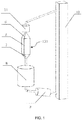
- FIG. 1 a solar heat collecting system and a solar heat absorber according to an embodiment of the present invention are shown.
- the solar heat absorber is denoted by a reference numeral 100.
- a solar heat absorber includes: an inlet 6 through which a heat collecting medium enters the solar heat absorber 100; a passage member 5 configured to be fluidly connected with the inlet 6 such that the heat collecting medium enters the passage member 5 through the inlet 6; and a collection member 7 configured to be fluidly connected with the passage member 5 such that the heat collecting medium enters the collection member 7 through the passage member 5.
- the passage member 5 may be placed obliquely or vertically.
- the heat collecting medium is a flow of ceramic particles.
- the ceramic particles are in a flow state, i.e. the flow of the ceramic particles.
- the flow of the ceramic particles is configured to have a flow speed of 0.1-2 m/s.
- the ceramic particles have a packing factor of 0.5-0.7.
- the packing factor as used herein means a ratio of a total volume of all the particles to a total volume of a space occupied by all the particles.
- the packing factor as used herein characterizes a concentration of the ceramic particles.
- FIG. 7 a relation between the ceramic particles and the space occupied by the ceramic particles is shown.
- the ceramic particles are shown. These ceramic particles are randomly packed with gaps among them. Assuming volumes of the particles are indicated by a1, a2, ..., an, respectively, and a space occupied by these ceramic particles has a length, a width and a height as shown in FIG. 7 , the packing factor is a ratio of a sum (a1+a2+a3+ ... +an) of the volumes of all the particles to a total volume (length*width*height) occupied by these packed particles.
- a flow speed and a packing condition and thus a value of the packing factor vary depending upon a position due to a randomness of the flow of the ceramic particles as the heat collecting medium in the heat absorber or the heat collecting system.
- FIG. 7 only schematically illustrates a method of calculating the packing factor and the space occupied by the ceramic particles as a cube.
- the space occupied by the ceramic particles may have any other shape such as a cylindrical shape, a conical shape or any other irregular shape.
- the packing factor is calculated by the ratio of the total volume of all the particles to the total volume of the space occupied by all the particles.
- the packing factor is a ratio of the sum (a1+a2+a3+ ... +an) of the volumes of all the particles to the total volume of the space (a space having any shape) occupied by these packed particles.
- each of the ceramic particles has a diameter of 0.1 mm-6 mm.
- a material of the ceramic particles is selected from one of a carbide ceramic, a nitride ceramic or an oxide ceramic, or a mixture thereof.
- the heat collecting medium in the heat absorber 100 is a flow of ceramic particles.
- the ceramic particle may have a spherical shape or a quasi-spherical shape, and is capable of flowing in the heat absorber 100. The flow of the ceramic particles enters the passage member 5 of the heat absorber 100 through the inlet 6 of the heat absorber 100.
- the flow of the ceramic particles is used as the heat collecting medium, and in an embodiment of the present invention the packing factor of the ceramic particles is in the range of 0.5-0.7, and preferably is about 0.57.
- Multi-hole passage units or chutes which are capable of being joined and which are made of heat absorbing materials/heat conducting materials having different transparencies, serve as a passage in which the heat collecting medium flows.
- the ceramic particles as the heat collecting medium may be made of a high-temperature resistant material, such as a carbide ceramic, a nitride ceramic or an oxide ceramic, for example, zirconia, alumina, zirconium nitride, silicon carbide, and the like, and a high-temperature resistant material composed of a mixture thereof, which can ensure that the heat absorber operates at a temperature in the range of 300-1200 °C and even above 1200°.
- a material such as a carbide can absorb/conduct a solar energy to the utmost extent due to its great thermal conductivity and radiation absorptivity.
- the diameter of the particle is in the range of 0.1-6 mm, and preferably is about 1 mm.
- a transparent material is selected as the material of the passage unit.
- a temperature resistant material having a low thermal conductivity and a high transmittance for example a high-temperature resistant material such as a carbide ceramic, a nitride ceramic or an oxide ceramic, and a mixture thereof, or a material such as quartz may be selected as the transparent material.
- An opaque material, not part of the present invention, may be a temperature resistant material having a high radiation absorptivity and a high thermal conductivity, for example a high-temperature resistant material of which a heat absorptivity is optimized, such as a carbide ceramic, a nitride ceramic or an oxide ceramic, and the like .
- the passage member 5 includes: a plurality of passage units 12, each including: a hole 14 in which the heat collecting medium flows; and a base body 15 surrounding the hole; and an outer layer portion 13 fixing the passage units 12 to be integrated.
- the passage member having a different shape may be formed by joining the plurality of passage units by fixing them through the outer layer portion 13 according to requirements.
- the passage unit 12 has a shape of a prism or a chute 16. As shown in FIG. 4 , an example in which the passage unit 12 of the present invention is the chute is shown.
- the heat collecting medium enters the passage unit in the form of the chute from an upper end of the passage unit, and flows into the collection member 7 from a lower end of the passage unit under the action of gravity after being heated by sunlight 4 (radiation energy flow).
- the passage member having a lattice structure or a honeycomb structure in a cross direction may be formed by joining, and a length of the passage member in a longitudinal direction may be adjusted according to requirements.
- the heat collecting medium is driven by gravity to flow through the holes of the passage units 12 and to be conveyed into the collection member 7 after absorbing heat.
- a density and a size of the holes 14 of the passage unit 12 may be set according to requirements.
- the above structure of the passage member is only an example, and does not constitute a limitation on the prevent invention, and those skilled in the art may also adopt passage members in other forms.
- the passage unit may be filled with a gas which may be air, or carbon dioxide, helium, nitrogen, oxygen or the like for increasing a heat exchange efficiency.
- a gas pressure in the passage may be in the range of 0.1-10 atmospheres, and preferably about 1 atmosphere.
- the collection member 7 has a funnel shape to control a flow rate and a flow speed of the heat collecting medium.
- the outer layer portion 13 fixes the passage units 12.
- Each of the base body 15 of the passage unit and the outer layer portion 13 is transparent material.
- a transparent material is selected for the base body 15 and a transparent material is also selected for the outer layer portion 13.
- the outer layer portion 13 may be a transparent or opaque material.
- the transparent material will transmit the sunlight 4 (radiation energy flow).
- the sunlight 4 radiation energy flow
- the sunlight 4 radiation energy flow
- the outer layer portion 13 is a transparent material and a gap is reserved between the passage units 12 and the outer cladding 13 and is evacuated to maintain internal heat.
- the outer layer portion 13 is an opaque material, the outer layer portion and the base body may be in close contact with each other to facilitate a heat transfer.
- a solar heat collecting system including the above solar heat absorber.
- the solar heat collecting system further includes: a heat collecting medium storage device 11 which is disposed upstream of the solar heat absorber 100 in a flow direction of the heat collecting medium, and which is in communication with the solar heat absorber 100 through a pipe such that the heat collecting medium flows from the heat collecting medium storage device 11 into the solar heat absorber 100; a heat exchanger 8 which is disposed downstream of the solar heat absorber 100 in the flow direction of the heat collecting medium, which is in communication with the solar heat absorber 100 through a pipe, and which is configured to transfer a heat absorbed by the heat collecting medium from the heat collecting medium; a heat collecting medium dust remover 9 which is disposed downstream of the heat exchanger 8 in the flow direction of the heat collecting medium, which is in communication with the heat exchanger 8 through a pipe, and which is configured to remove dusts from the heat collecting medium entering the heat collecting medium dust remover; and a heat collecting medium circulating device 10 which is disposed downstream of the heat collecting medium dust remover 9 in the
- the flow of the ceramic particles obtaining the heat flows out of the collection member 7 and then enters the heat exchanger 8 through a conveying pipe.
- the heat absorbed by the heat collecting medium may be transferred from the heat collecting medium to generate a power in a power generation system 3.
- the heat collecting medium is processed by the heat collecting medium dust remover 9 after the heat exchange, and then enters the heat collecting medium circulating device 10.
- the heat collecting medium is conveyed by the heat collecting medium circulating device 10 to the heat collecting medium storage device 11 located upstream of the heat absorber 100. After that, the heat collecting medium returns to the inlet 6 of the heat absorber through a pipe again for a next heat absorbing process.
- the solar heat collecting system circularly operates in this way.
- a radiation energy flow collected by a condensing device is projected onto the heat absorber 100, and is absorbed by a flow of dense ceramic particles.
- the flow of the dense ceramic particles in the heat absorber is driven by gravity to flow downwards through the hole of the passage at a vertical angle or an oblique angle.
- the dense ceramic particles can pass through the passage at a controllable flow speed due to an angle of inclination of the passage or a size of an opening of a funnel, thereby ensuring that heat can be sufficiently absorbed by/transferred to the heat collecting medium.
- a multihole structure of the passage member and a smaller size of the ceramic particles are favorable to a higher efficiency heat transfer.
- the heat collecting medium enters the heat collecting medium dust remover located downstream, to screen the heat collecting medium and remove dusts from the heat collecting medium.
- the heat collecting medium is conveyed by the heat collecting medium circulating device to the storage device located upstream of the heat absorber, and enters the heat collecting system again.
- the heat collecting medium dust remover may also be used as the heat collecting medium storage device.
- the solar heat absorber and the solar heat collecting system according to the present invention have a simplified structure, achieve a high efficiency absorption of the radiation energy flow under different conditions to the utmost extent, and remarkably increase the heat collecting efficiency.
- a flow state and a flow speed of the ceramic particles may be controlled by an angle of inclination of the passage member and a size of an outlet of the collecting device, while a block of the device is avoided.
- a solar power generation system including: the above solar heat collecting system.
- the solar power generation system further includes: a condensing system 1 configured to condense sunlight 4 to the solar heat collecting system 2; and a power generation system 3 which is configured such that a heat is transferred by the solar heat collecting system 2 into the power generation system 3 to generate a power.
- the condensing system 1 may be composed of an array of mirrors, and a tower, dish or groove condenser may be selected according to requirements. As shown in FIG. 5 , the groove condenser 17 is shown.
- the setting of the above condensing system is only an example, and is not intended to limit the prevent invention, and those skilled in the art may also adopt condensing systems in other forms.
- vapor such as water vapor, supercritical water, ultra-supercritical water, supercritical carbon dioxide, or the like may be used.
- the ceramic particles are used as the heat collecting medium, and the heat absorber having a simplified structure is provided.
- the improvements provide a heat collecting efficiency and a heat exchange efficiency. Further, both a power generation efficiency and an operational stability of the power generation system including the above heat absorber are remarkably improved.
Landscapes
- Engineering & Computer Science (AREA)
- Chemical & Material Sciences (AREA)
- Combustion & Propulsion (AREA)
- Life Sciences & Earth Sciences (AREA)
- Sustainable Development (AREA)
- Sustainable Energy (AREA)
- Mechanical Engineering (AREA)
- General Engineering & Computer Science (AREA)
- Thermal Sciences (AREA)
- Physics & Mathematics (AREA)
- Ceramic Engineering (AREA)
- Dispersion Chemistry (AREA)
- Heat-Exchange Devices With Radiators And Conduit Assemblies (AREA)
- Road Paving Structures (AREA)
- Photovoltaic Devices (AREA)
Description
- The present invention relates to a solar heat absorber, a solar heat collecting system and a solar power generation system.
- A solar heat absorber is a key component for converting light into heat in a solar power generation system, and its design has always been an important issue in the field of solar power generation. A heat absorbing medium in the solar heat absorber has an important influence on a heat collecting efficiency of the solar heat absorber. In the prior art, a heat absorber in which molten salt, air and saturated wet steam serve as the heat absorbing medium is often used, but the heat absorbing medium has disadvantages that it is easy to decompose at a high temperature, it cannot flow uniformly, it locally overheats, a device is easily corroded and failed, and the like.
-
US 2013/228163 A1 discloses a solar heat absorber according to the preamble ofclaim 1. - The object of the present invention is to provide a solar heat absorber, a solar heat collecting system and a solar power generation system, which can considerably raise a heat collecting efficiency to solve the problem in the prior art.
- According to the present invention, there is provided a solar heat absorber including: an inlet through which a heat collecting medium enters the solar heat absorber; a passage member configured to be fluidly connected with the inlet such that the heat collecting medium enters the passage member through the inlet; and a collection member configured to be fluidly connected with the passage member such that the heat collecting medium enters the collection member through the passage member.
- In accordance with the present invention, the heat collecting medium is a flow of ceramic particles.
- In accordance with embodiments of the present invention, the ceramic particles have a packing factor of 0.5-0.7.
- In accordance with embodiments of the present invention, each of the ceramic particles has a diameter of 0.1 mm-6 mm.
- In accordance with embodiments of the present invention, a material of the ceramic particles is selected from one of a carbide ceramic, a nitride ceramic or an oxide ceramic, or a mixture thereof.
- In accordance with embodiments of the present invention, the flow of the ceramic particles is configured to have a flow speed of 0.1-2 m/s.
- In accordance with the present invention, the passage member includes: a plurality of passage units, each including: a hole in which the heat collecting medium flows; and a base body surrounding the hole; and an outer layer portion fixing the passage units to be integrated.
- In accordance with embodiments of the present invention, the passage unit has a shape of a prism or a chute.
- In accordance with embodiments of the present invention, the collection member has a funnel shape.
- In accordance with another aspect of the present invention, there is provided a solar heat collecting system including the above solar heat absorber.
- In accordance with embodiments of the present invention, the solar heat collecting system further includes: a heat collecting medium storage device which is disposed upstream of the solar heat absorber in a flow direction of the heat collecting medium, and which is in communication with the solar heat absorber through a pipe such that the heat collecting medium flows from the heat collecting medium storage device into the solar heat absorber; a heat exchanger which is disposed downstream of the solar heat absorber in the flow direction of the heat collecting medium, which is in communication with the solar heat absorber through a pipe, and which is configured to transfer a heat absorbed by the heat collecting medium from the heat collecting medium; a heat collecting medium dust remover which is disposed downstream of the heat exchanger in the flow direction of the heat collecting medium, which is in communication with the heat exchanger through a pipe, and which is configured to remove dusts from the heat collecting medium entering the heat collecting medium dust remover; and a heat collecting medium circulating device which is disposed downstream of the heat collecting medium dust remover in the flow direction of the heat collecting medium, which is in communication with the heat collecting medium dust remover through a pipe, and which is configured to convey the heat collecting medium from the heat collecting medium dust remover into the heat collecting medium storage device.
- In accordance with a further aspect of the present invention, there is provided a solar power generation system including: the above solar heat collecting system.
- In accordance with embodiments of the present invention, the solar power generation system further includes: a condensing system configured to condense sunlight to the solar heat collecting system; and a power generation system which is configured such that a heat is transferred by the solar heat collecting system into the power generation system to generate a power.
- In the present invention, the ceramic particles are used as the heat collecting medium, and the heat absorber having a simplified structure is provided. The improvements provide a heat collecting efficiency and a heat exchange efficiency. Further, both a power generation efficiency and an operational stability of the power generation system including the above heat absorber are remarkably improved.
-
-
FIG. 1 is a schematic diagram of a solar heat collecting system including a solar heat absorber, according to an embodiment of the present invention; -
FIG. 2 is a schematic diagram showing a structure of passage units of the solar heat absorber according to an embodiment of the present invention; -
FIG. 3 is a schematic diagram showing a structure of a passage member of the solar heat absorber according to an embodiment of the present invention; -
FIG. 4 is a schematic diagram showing a partial structure of the passage units of the solar heat absorber according to an embodiment of the present invention; -
FIG. 5 is a schematic diagram showing a structure of the passage member of the solar heat absorber used in cooperation with a condenser, according to an embodiment of the present invention; and -
FIG. 6 is a schematic diagram showing a structure of a solar power generation system according to an embodiment of the present invention; -
FIG. 7 is a schematic diagram showing a relation between ceramic particles and a space occupied by the ceramic particles, according to an embodiment of the present invention. - Embodiments of the present invention will be now described in detail with reference to the accompanying drawings in which the same reference numerals correspond to the same elements. However, there are many different implementations of the present invention. The present invention should not be construed as being limited to the described embodiments, but the embodiments of the present invention are merely provided such that the present disclosure is comprehensive and complete and the concept of the present invention is fully conveyed to those skilled in the art.
- As shown in
FIG. 1 , a solar heat collecting system and a solar heat absorber according to an embodiment of the present invention are shown. The solar heat absorber is denoted by areference numeral 100. - According to the present invention, there is provided a solar heat absorber. The solar heat absorber includes: an
inlet 6 through which a heat collecting medium enters the solar heat absorber 100; apassage member 5 configured to be fluidly connected with theinlet 6 such that the heat collecting medium enters thepassage member 5 through theinlet 6; and acollection member 7 configured to be fluidly connected with thepassage member 5 such that the heat collecting medium enters thecollection member 7 through thepassage member 5. In embodiments of the present invention, thepassage member 5 may be placed obliquely or vertically. - According to the present invention, the heat collecting medium is a flow of ceramic particles. In other words, in the heat absorber, the ceramic particles are in a flow state, i.e. the flow of the ceramic particles. According to embodiments of the present invention, the flow of the ceramic particles is configured to have a flow speed of 0.1-2 m/s.
- According to embodiments of the present invention, the ceramic particles have a packing factor of 0.5-0.7. The packing factor as used herein means a ratio of a total volume of all the particles to a total volume of a space occupied by all the particles.
- Particularly, the packing factor as used herein characterizes a concentration of the ceramic particles. As shown in
FIG. 7 , a relation between the ceramic particles and the space occupied by the ceramic particles is shown. As shown inFIG. 7 , the ceramic particles are shown. These ceramic particles are randomly packed with gaps among them. Assuming volumes of the particles are indicated by a1, a2, ..., an, respectively, and a space occupied by these ceramic particles has a length, a width and a height as shown inFIG. 7 , the packing factor is a ratio of a sum (a1+a2+a3+ ... +an) of the volumes of all the particles to a total volume (length*width*height) occupied by these packed particles. On the other hand, a flow speed and a packing condition and thus a value of the packing factor vary depending upon a position due to a randomness of the flow of the ceramic particles as the heat collecting medium in the heat absorber or the heat collecting system. - Particularly, it is pointed out by the inventors that
FIG. 7 only schematically illustrates a method of calculating the packing factor and the space occupied by the ceramic particles as a cube. In actual applications, the space occupied by the ceramic particles may have any other shape such as a cylindrical shape, a conical shape or any other irregular shape. In this case, the packing factor is calculated by the ratio of the total volume of all the particles to the total volume of the space occupied by all the particles. In other words, the packing factor is a ratio of the sum (a1+a2+a3+ ... +an) of the volumes of all the particles to the total volume of the space (a space having any shape) occupied by these packed particles. - According to embodiments of the present invention, each of the ceramic particles has a diameter of 0.1 mm-6 mm.
- According to embodiments of the present invention, a material of the ceramic particles is selected from one of a carbide ceramic, a nitride ceramic or an oxide ceramic, or a mixture thereof.
- Specifically, the heat collecting medium in the heat absorber 100 is a flow of ceramic particles. In embodiments of the present invention, the ceramic particle may have a spherical shape or a quasi-spherical shape, and is capable of flowing in the heat absorber 100. The flow of the ceramic particles enters the
passage member 5 of the heat absorber 100 through theinlet 6 of the heat absorber 100. - In the present invention, the flow of the ceramic particles is used as the heat collecting medium, and in an embodiment of the present invention the packing factor of the ceramic particles is in the range of 0.5-0.7, and preferably is about 0.57. Multi-hole passage units or chutes, which are capable of being joined and which are made of heat absorbing materials/heat conducting materials having different transparencies, serve as a passage in which the heat collecting medium flows. The ceramic particles as the heat collecting medium (a heat transferring medium) may be made of a high-temperature resistant material, such as a carbide ceramic, a nitride ceramic or an oxide ceramic, for example, zirconia, alumina, zirconium nitride, silicon carbide, and the like, and a high-temperature resistant material composed of a mixture thereof, which can ensure that the heat absorber operates at a temperature in the range of 300-1200 °C and even above 1200°. A material such as a carbide can absorb/conduct a solar energy to the utmost extent due to its great thermal conductivity and radiation absorptivity. The diameter of the particle is in the range of 0.1-6 mm, and preferably is about 1 mm.
- In addition, a transparent material is selected as the material of the passage unit. A temperature resistant material having a low thermal conductivity and a high transmittance, for example a high-temperature resistant material such as a carbide ceramic, a nitride ceramic or an oxide ceramic, and a mixture thereof, or a material such as quartz may be selected as the transparent material. An opaque material, not part of the present invention, may be a temperature resistant material having a high radiation absorptivity and a high thermal conductivity, for example a high-temperature resistant material of which a heat absorptivity is optimized, such as a carbide ceramic, a nitride ceramic or an oxide ceramic, and the like .
- Particularly, the above materials are not intended to limit the present invention, and those skilled in the art may also adopt other suitable materials according to the teaching of the above technical solutions.
- According to embodiments of the present invention, as shown in
FIGS. 2 and3 , thepassage member 5 includes: a plurality ofpassage units 12, each including: ahole 14 in which the heat collecting medium flows; and abase body 15 surrounding the hole; and anouter layer portion 13 fixing thepassage units 12 to be integrated. The passage member having a different shape may be formed by joining the plurality of passage units by fixing them through theouter layer portion 13 according to requirements. - According to embodiments of the present invention, the
passage unit 12 has a shape of a prism or achute 16. As shown inFIG. 4 , an example in which thepassage unit 12 of the present invention is the chute is shown. The heat collecting medium enters the passage unit in the form of the chute from an upper end of the passage unit, and flows into thecollection member 7 from a lower end of the passage unit under the action of gravity after being heated by sunlight 4 (radiation energy flow). In addition, if a prismatic structure is selected for thepassage member 5, the passage member having a lattice structure or a honeycomb structure in a cross direction may be formed by joining, and a length of the passage member in a longitudinal direction may be adjusted according to requirements. The heat collecting medium is driven by gravity to flow through the holes of thepassage units 12 and to be conveyed into thecollection member 7 after absorbing heat. - A density and a size of the
holes 14 of thepassage unit 12 may be set according to requirements. Particularly, the above structure of the passage member is only an example, and does not constitute a limitation on the prevent invention, and those skilled in the art may also adopt passage members in other forms. - Further, the passage unit may be filled with a gas which may be air, or carbon dioxide, helium, nitrogen, oxygen or the like for increasing a heat exchange efficiency. A gas pressure in the passage may be in the range of 0.1-10 atmospheres, and preferably about 1 atmosphere.
- According to embodiments of the present invention, as shown in
FIG. 1 , thecollection member 7 has a funnel shape to control a flow rate and a flow speed of the heat collecting medium. - In the present invention, the
outer layer portion 13 fixes thepassage units 12. Each of thebase body 15 of the passage unit and theouter layer portion 13 is transparent material. In the present invention, a transparent material is selected for thebase body 15 and a transparent material is also selected for theouter layer portion 13. In an embodiment not part of the present invention, if an opaque material is selected for thebase body 15, theouter layer portion 13 may be a transparent or opaque material. When each of the base body and the outer layer portion is a transparent material, the transparent material will transmit the sunlight 4 (radiation energy flow). When each of the base body and the outer layer portion is an opaque material, the sunlight 4 (radiation energy flow) will be absorbed by the opaque material and will be transferred to the heat collecting medium in thehole 14. In the present invention, theouter layer portion 13 is a transparent material and a gap is reserved between thepassage units 12 and theouter cladding 13 and is evacuated to maintain internal heat. In an embodiment not part of the present invention, if theouter layer portion 13 is an opaque material, the outer layer portion and the base body may be in close contact with each other to facilitate a heat transfer. - In accordance with another aspect of the present invention, there is provided a solar heat collecting system including the above solar heat absorber.
- According to embodiments of the present invention, as shown in
FIG. 1 , the solar heat collecting system further includes: a heat collecting medium storage device 11 which is disposed upstream of the solar heat absorber 100 in a flow direction of the heat collecting medium, and which is in communication with the solar heat absorber 100 through a pipe such that the heat collecting medium flows from the heat collecting medium storage device 11 into the solar heat absorber 100; a heat exchanger 8 which is disposed downstream of the solar heat absorber 100 in the flow direction of the heat collecting medium, which is in communication with the solar heat absorber 100 through a pipe, and which is configured to transfer a heat absorbed by the heat collecting medium from the heat collecting medium; a heat collecting medium dust remover 9 which is disposed downstream of the heat exchanger 8 in the flow direction of the heat collecting medium, which is in communication with the heat exchanger 8 through a pipe, and which is configured to remove dusts from the heat collecting medium entering the heat collecting medium dust remover; and a heat collecting medium circulating device 10 which is disposed downstream of the heat collecting medium dust remover 9 in the flow direction of the heat collecting medium, which is in communication with the heat collecting medium dust remover 9 through a pipe, and which is configured to convey the heat collecting medium from the heat collecting medium dust remover 9 into the heat collecting medium storage device 11. - As shown in
FIGS. 1 and6 , the flow of the ceramic particles obtaining the heat flows out of thecollection member 7 and then enters theheat exchanger 8 through a conveying pipe. In theheat exchanger 8, the heat absorbed by the heat collecting medium may be transferred from the heat collecting medium to generate a power in apower generation system 3. The heat collecting medium is processed by the heat collectingmedium dust remover 9 after the heat exchange, and then enters the heat collecting medium circulatingdevice 10. The heat collecting medium is conveyed by the heat collecting medium circulatingdevice 10 to the heat collectingmedium storage device 11 located upstream of theheat absorber 100. After that, the heat collecting medium returns to theinlet 6 of the heat absorber through a pipe again for a next heat absorbing process. The solar heat collecting system circularly operates in this way. - An operational process of the solar heat collecting system of the present invention is described in brief as below.
- As shown in
FIGS. 1 and6 , a radiation energy flow collected by a condensing device is projected onto theheat absorber 100, and is absorbed by a flow of dense ceramic particles. The flow of the dense ceramic particles in the heat absorber is driven by gravity to flow downwards through the hole of the passage at a vertical angle or an oblique angle. The dense ceramic particles can pass through the passage at a controllable flow speed due to an angle of inclination of the passage or a size of an opening of a funnel, thereby ensuring that heat can be sufficiently absorbed by/transferred to the heat collecting medium. A multihole structure of the passage member and a smaller size of the ceramic particles are favorable to a higher efficiency heat transfer. The ceramic particles absorbing the heat flow through the hole into a collection device connected to a bottom of the passage, and then enter the heat exchanger located downstream, so that the heat is transferred from the ceramic particles to generate a power. After an end of the heat exchange, the heat collecting medium enters the heat collecting medium dust remover located downstream, to screen the heat collecting medium and remove dusts from the heat collecting medium. After that, the heat collecting medium is conveyed by the heat collecting medium circulating device to the storage device located upstream of the heat absorber, and enters the heat collecting system again. The heat collecting medium dust remover may also be used as the heat collecting medium storage device. - The solar heat absorber and the solar heat collecting system according to the present invention have a simplified structure, achieve a high efficiency absorption of the radiation energy flow under different conditions to the utmost extent, and remarkably increase the heat collecting efficiency. In addition, since there is no inserted member, problems of fatigue and wear of the inserted member are avoided. A flow state and a flow speed of the ceramic particles may be controlled by an angle of inclination of the passage member and a size of an outlet of the collecting device, while a block of the device is avoided.
- In accordance with a further aspect of the present invention, there is provided a solar power generation system including: the above solar heat collecting system.
- According to embodiments of the present invention, as shown in
FIG. 6 , the solar power generation system further includes: a condensingsystem 1 configured to condensesunlight 4 to the solarheat collecting system 2; and apower generation system 3 which is configured such that a heat is transferred by the solarheat collecting system 2 into thepower generation system 3 to generate a power. - In embodiments of the present invention, the condensing
system 1 may be composed of an array of mirrors, and a tower, dish or groove condenser may be selected according to requirements. As shown inFIG. 5 , thegroove condenser 17 is shown. Of course, the setting of the above condensing system is only an example, and is not intended to limit the prevent invention, and those skilled in the art may also adopt condensing systems in other forms. - Further, as a working medium in the power generation system, vapor, such as water vapor, supercritical water, ultra-supercritical water, supercritical carbon dioxide, or the like may be used.
- In the present invention, the ceramic particles are used as the heat collecting medium, and the heat absorber having a simplified structure is provided. The improvements provide a heat collecting efficiency and a heat exchange efficiency. Further, both a power generation efficiency and an operational stability of the power generation system including the above heat absorber are remarkably improved.
- While the embodiments of the present invention have been shown and described, it would be appreciated by those skilled in the art that changes may be made therein, and the changes will fall within the scope of the present invention which is defined in the appended claims.
Claims (11)
- A solar heat absorber (100) comprising:a heat collecting medium;an inlet (6) through which the heat collecting medium enters the solar heat absorber (100);a passage member (5) configured to be fluidly connected with the inlet (6) such that the heat collecting medium enters the passage member (5) through the inlet (6); anda collection member (7) configured to be fluidly connected with the passage member (5) such that the heat collecting medium enters the collection member (7) through the passage member (5),wherein the heat collecting medium is a flow of ceramic particles, characterized in that the passage member (5) comprises:a plurality of passage units (12), each comprising: a plurality of holes (14) in which the heat collecting medium flows; and a base body (15) surrounding the plurality of holes (14); andan outer layer portion (13) surrounding the plurality of passage units (12) and fixing the plurality of passage units (12) to be integrated, wherein a vacuum gap is formed between the plurality of passage units (12) and the outer layer portion (13), wherein the base body (15) of each of the plurality of passage units (12) and the outer layer portion (13) are transparent to transmit sunlight.
- The solar heat absorber of claim 1, wherein the ceramic particles have a packing factor of 0.5-0.7, wherein the packing factor is a ratio of total volume of all the particles to a total volume of a space occupied by all the particles.
- The solar heat absorber of claim 1, wherein each of the ceramic particles has a diameter of 0.1 mm-6 mm.
- The solar heat absorber of claim 1, wherein a material of the ceramic particles is selected from one of a carbide ceramic, a nitride ceramic or an oxide ceramic, or a mixture thereof.
- The solar heat absorber of claim 1, wherein the flow of the ceramic particles is configured to have a flow speed of 0.1-2 m/s.
- The solar heat absorber of claim 1, wherein the passage unit (12) has a shape of a prism or a chute.
- The solar heat absorber of claim 1, wherein the collection member (7) has a funnel shape.
- A solar heat collecting system (2) comprising: the solar heat absorber (100) of claim 1.
- The solar heat collecting system (2) of claim 8, further comprising a heat collecting medium storage device (11) which is disposed upstream of the solar heat absorber (100) in a flow direction of the heat collecting medium, and which is in communication with the solar heat absorber (100) through a pipe such that the heat collecting medium flows from the heat collecting medium storage device (11) into the solar heat absorber (100); a heat exchanger (8) which is disposed downstream of the solar heat absorber (100) in the flow direction of the heat collecting medium, which is in communication with the solar heat absorber (100) through a pipe, and which is configured to transfer a heat absorbed by the heat collecting medium from the heat collecting medium; a heat collecting medium dust remover (9) which is disposed downstream of the heat exchanger (8) in the flow direction of the heat collecting medium, which is in communication with the heat exchanger (8) through a pipe, and which is configured to remove dusts from the heat collecting medium entering the heat collecting medium dust remover (9); and a heat collecting medium circulating device (10) which is disposed downstream of the heat collecting medium dust remover (9) in the flow direction of the heat collecting medium, which is in communication with the heat collecting medium dust remover (9) through a pipe, and which is configured to convey the heat collecting medium from the heat collecting medium dust remover (9) into the heat collecting medium storage device (11).
- A solar power generation system (3) comprising:
the solar heat collecting system (2) of claim 8. - The solar power generation system (3) of claim 10, further comprising:a condensing system (1) configured to condense sunlight to the solar heat collecting system (2); anda power generation system (3) which is configured such that a heat is transferred by the solar heat collecting system (2) into the power generation system (3) to generate a power
Priority Applications (1)
| Application Number | Priority Date | Filing Date | Title |
|---|---|---|---|
| HUE16925632A HUE056103T2 (en) | 2016-12-26 | 2016-12-26 | Solar collector, solar collector assembly and solar energy generator |
Applications Claiming Priority (1)
| Application Number | Priority Date | Filing Date | Title |
|---|---|---|---|
| PCT/CN2016/112040 WO2018119556A1 (en) | 2016-12-26 | 2016-12-26 | Solar energy heat absorption device, solar energy heat collection system and solar energy power generation system |
Publications (3)
| Publication Number | Publication Date |
|---|---|
| EP3561409A1 EP3561409A1 (en) | 2019-10-30 |
| EP3561409A4 EP3561409A4 (en) | 2020-06-03 |
| EP3561409B1 true EP3561409B1 (en) | 2021-07-21 |
Family
ID=62706680
Family Applications (1)
| Application Number | Title | Priority Date | Filing Date |
|---|---|---|---|
| EP16925632.8A Active EP3561409B1 (en) | 2016-12-26 | 2016-12-26 | Solar energy heat absorption device, solar energy heat collection system and solar energy power generation system |
Country Status (4)
| Country | Link |
|---|---|
| US (1) | US11193695B2 (en) |
| EP (1) | EP3561409B1 (en) |
| HU (1) | HUE056103T2 (en) |
| WO (1) | WO2018119556A1 (en) |
Families Citing this family (2)
| Publication number | Priority date | Publication date | Assignee | Title |
|---|---|---|---|---|
| CN113323828B (en) * | 2021-06-11 | 2024-05-07 | 西安热工研究院有限公司 | Efficient particle heat storage comprehensive utilization system and method |
| CN113390190B (en) * | 2021-07-14 | 2022-06-21 | 吉林建筑大学 | Secondary reflection type particle heat absorber |
Citations (1)
| Publication number | Priority date | Publication date | Assignee | Title |
|---|---|---|---|---|
| WO2014184961A1 (en) * | 2013-05-17 | 2014-11-20 | 東京窯業株式会社 | Heat collector for solar thermal power generation |
Family Cites Families (17)
| Publication number | Priority date | Publication date | Assignee | Title |
|---|---|---|---|---|
| JP3862485B2 (en) | 2000-08-02 | 2006-12-27 | 独立行政法人科学技術振興機構 | Pneumatic solar collector using a porous ceramic sphere layer as a heat collecting vent layer |
| CN101122422B (en) * | 2007-05-10 | 2010-12-08 | 中国科学院电工研究所 | Fluidized bed high-temperature heat absorber for solar tower thermal power generation and its "heat absorption-heat storage" double fluidized bed system |
| CN102171452A (en) * | 2008-10-13 | 2011-08-31 | 圣戈本陶瓷及塑料股份有限公司 | System and process for using solar radiation to produce electricity |
| CN101634490B (en) * | 2009-08-04 | 2010-12-01 | 中国科学院电工研究所 | Solid ball flow absorber for solar thermal power generation |
| FR2966567B1 (en) * | 2010-10-20 | 2014-11-14 | Centre Nat Rech Scient | COLLECTOR SOLAR ENERGY DEVICE |
| JP5743485B2 (en) * | 2010-10-25 | 2015-07-01 | イビデン株式会社 | Heat collecting receiver and solar power generator |
| CN103148596A (en) | 2011-12-06 | 2013-06-12 | 陕西科林能源发展股份有限公司 | Solar heat collecting device using heat pipes |
| US20130228163A1 (en) * | 2012-03-01 | 2013-09-05 | David Wait | Thermal transfer apparatus and method therefor |
| JP2014184961A (en) | 2013-03-21 | 2014-10-02 | Toshiba Corp | Filling method of particles and filling device of particles |
| CN103216952B (en) * | 2013-04-15 | 2015-02-11 | 中国科学院电工研究所 | Internal circulation type solid particle air heat absorber for solar thermal power generation |
| DE102014106320B4 (en) * | 2014-05-06 | 2020-10-29 | Deutsches Zentrum für Luft- und Raumfahrt e.V. | Solar radiation receiving device |
| CN105318579A (en) | 2015-02-07 | 2016-02-10 | 成都奥能普科技有限公司 | Solid particle block tower-type solar pulse driven heat-exchange and heat-transmission system |
| CN105318577A (en) | 2015-02-07 | 2016-02-10 | 成都奥能普科技有限公司 | Solid particle block tower-type solar fluidization driven heat-exchange and heat-transmission system |
| CN105318562A (en) | 2015-02-07 | 2016-02-10 | 成都奥能普科技有限公司 | Tower type solid particle solar light-heat converter |
| US10508834B1 (en) * | 2015-04-09 | 2019-12-17 | National Technology & Engineering Solutions Of Sandia, Llc | Falling particle solar receivers |
| US10107523B2 (en) * | 2015-12-07 | 2018-10-23 | Carbo Ceramics Inc. | Ceramic particles for use in a solar power tower |
| CN113108482A (en) | 2016-12-26 | 2021-07-13 | 中国科学院近代物理研究所 | Solar heat absorber, solar heat collection system and solar power generation system |
-
2016
- 2016-12-26 EP EP16925632.8A patent/EP3561409B1/en active Active
- 2016-12-26 WO PCT/CN2016/112040 patent/WO2018119556A1/en not_active Ceased
- 2016-12-26 US US16/473,464 patent/US11193695B2/en not_active Expired - Fee Related
- 2016-12-26 HU HUE16925632A patent/HUE056103T2/en unknown
Patent Citations (1)
| Publication number | Priority date | Publication date | Assignee | Title |
|---|---|---|---|---|
| WO2014184961A1 (en) * | 2013-05-17 | 2014-11-20 | 東京窯業株式会社 | Heat collector for solar thermal power generation |
Also Published As
| Publication number | Publication date |
|---|---|
| WO2018119556A1 (en) | 2018-07-05 |
| US20200149782A1 (en) | 2020-05-14 |
| EP3561409A4 (en) | 2020-06-03 |
| HUE056103T2 (en) | 2022-01-28 |
| EP3561409A1 (en) | 2019-10-30 |
| US11193695B2 (en) | 2021-12-07 |
Similar Documents
| Publication | Publication Date | Title |
|---|---|---|
| CN113108482A (en) | Solar heat absorber, solar heat collection system and solar power generation system | |
| CN108458506B (en) | A solid particle heat absorber for solar thermal power generation | |
| CN105135716B (en) | Tubular solar heat absorber provided with insert and solid particles | |
| KR101895084B1 (en) | High-temperature heat store for solar-thermal power plants | |
| JP6165743B2 (en) | Thermal energy storage system using sunlight | |
| TW201207330A (en) | Storing and transport device and system with high efficiency | |
| JP6134691B2 (en) | System for passively filtering radioactive materials | |
| ES2835901T3 (en) | Solar receiver | |
| CN102679578B (en) | Solar particle heat absorber with cyclone separators | |
| US11193695B2 (en) | Solar heat absorber, solar heat collecting system and solar power generation system with ceramic particles | |
| CN108592419A (en) | A kind of solar energy thermal-power-generating is with delaying falling type solid particle heat dump | |
| CN106424111A (en) | Soil restoration device and method | |
| CN103216952A (en) | Internal circulation type solid particle air heat absorber for solar thermal power generation | |
| KR102542967B1 (en) | Continuous Direct Air Capture system and Method | |
| CN105251305A (en) | Ceramic dust removal equipment for tobacco cutting and process | |
| CN103055777A (en) | Cavity-type solar high-temperature thermochemical reactor | |
| CN102818379A (en) | Solid-particle air heat absorber used for solar thermal power plant | |
| CN201101987Y (en) | Dust-removing heat-exchanger | |
| CN206478878U (en) | Solar heat absorber, solar thermal collection system and solar power system | |
| SE468076B (en) | WATER TREATMENT PROCEDURES FOR EXAMINATION AND DISPOSAL OF HAZARDOUS SMOKING AND EXHAUST MATERIALS | |
| CN104785185B (en) | A kind of have the suspended particles system solar heat chemical reactor preventing optical window thermal deformation and crushing | |
| CN204051272U (en) | A kind of high temperature cloth exhaust dust device with bag | |
| CN106362538A (en) | Wet flue gas dehumidification and emission reduction device | |
| CN204710007U (en) | A kind of emission-control equipment | |
| KR20180077371A (en) | Solar collector of direct absorption type |
Legal Events
| Date | Code | Title | Description |
|---|---|---|---|
| STAA | Information on the status of an ep patent application or granted ep patent |
Free format text: STATUS: THE INTERNATIONAL PUBLICATION HAS BEEN MADE |
|
| PUAI | Public reference made under article 153(3) epc to a published international application that has entered the european phase |
Free format text: ORIGINAL CODE: 0009012 |
|
| STAA | Information on the status of an ep patent application or granted ep patent |
Free format text: STATUS: REQUEST FOR EXAMINATION WAS MADE |
|
| 17P | Request for examination filed |
Effective date: 20190723 |
|
| AK | Designated contracting states |
Kind code of ref document: A1 Designated state(s): AL AT BE BG CH CY CZ DE DK EE ES FI FR GB GR HR HU IE IS IT LI LT LU LV MC MK MT NL NO PL PT RO RS SE SI SK SM TR |
|
| AX | Request for extension of the european patent |
Extension state: BA ME |
|
| DAV | Request for validation of the european patent (deleted) | ||
| DAX | Request for extension of the european patent (deleted) | ||
| A4 | Supplementary search report drawn up and despatched |
Effective date: 20200508 |
|
| RIC1 | Information provided on ipc code assigned before grant |
Ipc: F24S 10/00 20180101AFI20200501BHEP |
|
| STAA | Information on the status of an ep patent application or granted ep patent |
Free format text: STATUS: EXAMINATION IS IN PROGRESS |
|
| 17Q | First examination report despatched |
Effective date: 20201002 |
|
| REG | Reference to a national code |
Ref country code: DE Ref legal event code: R079 Ref document number: 602016061148 Country of ref document: DE Free format text: PREVIOUS MAIN CLASS: F24S0010000000 Ipc: F24S0010400000 |
|
| RIC1 | Information provided on ipc code assigned before grant |
Ipc: F24S 10/70 20180101ALI20210302BHEP Ipc: F24S 10/40 20180101AFI20210302BHEP |
|
| GRAP | Despatch of communication of intention to grant a patent |
Free format text: ORIGINAL CODE: EPIDOSNIGR1 |
|
| STAA | Information on the status of an ep patent application or granted ep patent |
Free format text: STATUS: GRANT OF PATENT IS INTENDED |
|
| INTG | Intention to grant announced |
Effective date: 20210428 |
|
| GRAS | Grant fee paid |
Free format text: ORIGINAL CODE: EPIDOSNIGR3 |
|
| GRAA | (expected) grant |
Free format text: ORIGINAL CODE: 0009210 |
|
| STAA | Information on the status of an ep patent application or granted ep patent |
Free format text: STATUS: THE PATENT HAS BEEN GRANTED |
|
| AK | Designated contracting states |
Kind code of ref document: B1 Designated state(s): AL AT BE BG CH CY CZ DE DK EE ES FI FR GB GR HR HU IE IS IT LI LT LU LV MC MK MT NL NO PL PT RO RS SE SI SK SM TR |
|
| REG | Reference to a national code |
Ref country code: GB Ref legal event code: FG4D |
|
| REG | Reference to a national code |
Ref country code: CH Ref legal event code: EP |
|
| REG | Reference to a national code |
Ref country code: DE Ref legal event code: R096 Ref document number: 602016061148 Country of ref document: DE |
|
| REG | Reference to a national code |
Ref country code: AT Ref legal event code: REF Ref document number: 1412940 Country of ref document: AT Kind code of ref document: T Effective date: 20210815 |
|
| REG | Reference to a national code |
Ref country code: IE Ref legal event code: FG4D |
|
| REG | Reference to a national code |
Ref country code: LT Ref legal event code: MG9D |
|
| REG | Reference to a national code |
Ref country code: NL Ref legal event code: MP Effective date: 20210721 |
|
| REG | Reference to a national code |
Ref country code: AT Ref legal event code: MK05 Ref document number: 1412940 Country of ref document: AT Kind code of ref document: T Effective date: 20210721 |
|
| REG | Reference to a national code |
Ref country code: HU Ref legal event code: AG4A Ref document number: E056103 Country of ref document: HU |
|
| PG25 | Lapsed in a contracting state [announced via postgrant information from national office to epo] |
Ref country code: BG Free format text: LAPSE BECAUSE OF FAILURE TO SUBMIT A TRANSLATION OF THE DESCRIPTION OR TO PAY THE FEE WITHIN THE PRESCRIBED TIME-LIMIT Effective date: 20211021 Ref country code: AT Free format text: LAPSE BECAUSE OF FAILURE TO SUBMIT A TRANSLATION OF THE DESCRIPTION OR TO PAY THE FEE WITHIN THE PRESCRIBED TIME-LIMIT Effective date: 20210721 Ref country code: LT Free format text: LAPSE BECAUSE OF FAILURE TO SUBMIT A TRANSLATION OF THE DESCRIPTION OR TO PAY THE FEE WITHIN THE PRESCRIBED TIME-LIMIT Effective date: 20210721 Ref country code: NL Free format text: LAPSE BECAUSE OF FAILURE TO SUBMIT A TRANSLATION OF THE DESCRIPTION OR TO PAY THE FEE WITHIN THE PRESCRIBED TIME-LIMIT Effective date: 20210721 Ref country code: PT Free format text: LAPSE BECAUSE OF FAILURE TO SUBMIT A TRANSLATION OF THE DESCRIPTION OR TO PAY THE FEE WITHIN THE PRESCRIBED TIME-LIMIT Effective date: 20211122 Ref country code: NO Free format text: LAPSE BECAUSE OF FAILURE TO SUBMIT A TRANSLATION OF THE DESCRIPTION OR TO PAY THE FEE WITHIN THE PRESCRIBED TIME-LIMIT Effective date: 20211021 Ref country code: HR Free format text: LAPSE BECAUSE OF FAILURE TO SUBMIT A TRANSLATION OF THE DESCRIPTION OR TO PAY THE FEE WITHIN THE PRESCRIBED TIME-LIMIT Effective date: 20210721 Ref country code: FI Free format text: LAPSE BECAUSE OF FAILURE TO SUBMIT A TRANSLATION OF THE DESCRIPTION OR TO PAY THE FEE WITHIN THE PRESCRIBED TIME-LIMIT Effective date: 20210721 Ref country code: ES Free format text: LAPSE BECAUSE OF FAILURE TO SUBMIT A TRANSLATION OF THE DESCRIPTION OR TO PAY THE FEE WITHIN THE PRESCRIBED TIME-LIMIT Effective date: 20210721 Ref country code: RS Free format text: LAPSE BECAUSE OF FAILURE TO SUBMIT A TRANSLATION OF THE DESCRIPTION OR TO PAY THE FEE WITHIN THE PRESCRIBED TIME-LIMIT Effective date: 20210721 Ref country code: SE Free format text: LAPSE BECAUSE OF FAILURE TO SUBMIT A TRANSLATION OF THE DESCRIPTION OR TO PAY THE FEE WITHIN THE PRESCRIBED TIME-LIMIT Effective date: 20210721 |
|
| PG25 | Lapsed in a contracting state [announced via postgrant information from national office to epo] |
Ref country code: PL Free format text: LAPSE BECAUSE OF FAILURE TO SUBMIT A TRANSLATION OF THE DESCRIPTION OR TO PAY THE FEE WITHIN THE PRESCRIBED TIME-LIMIT Effective date: 20210721 Ref country code: LV Free format text: LAPSE BECAUSE OF FAILURE TO SUBMIT A TRANSLATION OF THE DESCRIPTION OR TO PAY THE FEE WITHIN THE PRESCRIBED TIME-LIMIT Effective date: 20210721 Ref country code: GR Free format text: LAPSE BECAUSE OF FAILURE TO SUBMIT A TRANSLATION OF THE DESCRIPTION OR TO PAY THE FEE WITHIN THE PRESCRIBED TIME-LIMIT Effective date: 20211022 |
|
| REG | Reference to a national code |
Ref country code: DE Ref legal event code: R097 Ref document number: 602016061148 Country of ref document: DE |
|
| PG25 | Lapsed in a contracting state [announced via postgrant information from national office to epo] |
Ref country code: DK Free format text: LAPSE BECAUSE OF FAILURE TO SUBMIT A TRANSLATION OF THE DESCRIPTION OR TO PAY THE FEE WITHIN THE PRESCRIBED TIME-LIMIT Effective date: 20210721 |
|
| PLBE | No opposition filed within time limit |
Free format text: ORIGINAL CODE: 0009261 |
|
| STAA | Information on the status of an ep patent application or granted ep patent |
Free format text: STATUS: NO OPPOSITION FILED WITHIN TIME LIMIT |
|
| PG25 | Lapsed in a contracting state [announced via postgrant information from national office to epo] |
Ref country code: SM Free format text: LAPSE BECAUSE OF FAILURE TO SUBMIT A TRANSLATION OF THE DESCRIPTION OR TO PAY THE FEE WITHIN THE PRESCRIBED TIME-LIMIT Effective date: 20210721 Ref country code: SK Free format text: LAPSE BECAUSE OF FAILURE TO SUBMIT A TRANSLATION OF THE DESCRIPTION OR TO PAY THE FEE WITHIN THE PRESCRIBED TIME-LIMIT Effective date: 20210721 Ref country code: RO Free format text: LAPSE BECAUSE OF FAILURE TO SUBMIT A TRANSLATION OF THE DESCRIPTION OR TO PAY THE FEE WITHIN THE PRESCRIBED TIME-LIMIT Effective date: 20210721 Ref country code: EE Free format text: LAPSE BECAUSE OF FAILURE TO SUBMIT A TRANSLATION OF THE DESCRIPTION OR TO PAY THE FEE WITHIN THE PRESCRIBED TIME-LIMIT Effective date: 20210721 Ref country code: AL Free format text: LAPSE BECAUSE OF FAILURE TO SUBMIT A TRANSLATION OF THE DESCRIPTION OR TO PAY THE FEE WITHIN THE PRESCRIBED TIME-LIMIT Effective date: 20210721 |
|
| 26N | No opposition filed |
Effective date: 20220422 |
|
| PG25 | Lapsed in a contracting state [announced via postgrant information from national office to epo] |
Ref country code: MC Free format text: LAPSE BECAUSE OF FAILURE TO SUBMIT A TRANSLATION OF THE DESCRIPTION OR TO PAY THE FEE WITHIN THE PRESCRIBED TIME-LIMIT Effective date: 20210721 Ref country code: IT Free format text: LAPSE BECAUSE OF FAILURE TO SUBMIT A TRANSLATION OF THE DESCRIPTION OR TO PAY THE FEE WITHIN THE PRESCRIBED TIME-LIMIT Effective date: 20210721 |
|
| REG | Reference to a national code |
Ref country code: CH Ref legal event code: PL |
|
| GBPC | Gb: european patent ceased through non-payment of renewal fee |
Effective date: 20211226 |
|
| REG | Reference to a national code |
Ref country code: BE Ref legal event code: MM Effective date: 20211231 |
|
| PG25 | Lapsed in a contracting state [announced via postgrant information from national office to epo] |
Ref country code: LU Free format text: LAPSE BECAUSE OF NON-PAYMENT OF DUE FEES Effective date: 20211226 Ref country code: IE Free format text: LAPSE BECAUSE OF NON-PAYMENT OF DUE FEES Effective date: 20211226 Ref country code: GB Free format text: LAPSE BECAUSE OF NON-PAYMENT OF DUE FEES Effective date: 20211226 |
|
| PG25 | Lapsed in a contracting state [announced via postgrant information from national office to epo] |
Ref country code: FR Free format text: LAPSE BECAUSE OF NON-PAYMENT OF DUE FEES Effective date: 20211231 Ref country code: BE Free format text: LAPSE BECAUSE OF NON-PAYMENT OF DUE FEES Effective date: 20211231 |
|
| PG25 | Lapsed in a contracting state [announced via postgrant information from national office to epo] |
Ref country code: LI Free format text: LAPSE BECAUSE OF NON-PAYMENT OF DUE FEES Effective date: 20211231 Ref country code: CH Free format text: LAPSE BECAUSE OF NON-PAYMENT OF DUE FEES Effective date: 20211231 |
|
| PG25 | Lapsed in a contracting state [announced via postgrant information from national office to epo] |
Ref country code: CY Free format text: LAPSE BECAUSE OF FAILURE TO SUBMIT A TRANSLATION OF THE DESCRIPTION OR TO PAY THE FEE WITHIN THE PRESCRIBED TIME-LIMIT Effective date: 20210721 |
|
| P01 | Opt-out of the competence of the unified patent court (upc) registered |
Effective date: 20230601 |
|
| PG25 | Lapsed in a contracting state [announced via postgrant information from national office to epo] |
Ref country code: MK Free format text: LAPSE BECAUSE OF FAILURE TO SUBMIT A TRANSLATION OF THE DESCRIPTION OR TO PAY THE FEE WITHIN THE PRESCRIBED TIME-LIMIT Effective date: 20210721 |
|
| PG25 | Lapsed in a contracting state [announced via postgrant information from national office to epo] |
Ref country code: TR Free format text: LAPSE BECAUSE OF FAILURE TO SUBMIT A TRANSLATION OF THE DESCRIPTION OR TO PAY THE FEE WITHIN THE PRESCRIBED TIME-LIMIT Effective date: 20210721 |
|
| PG25 | Lapsed in a contracting state [announced via postgrant information from national office to epo] |
Ref country code: MT Free format text: LAPSE BECAUSE OF FAILURE TO SUBMIT A TRANSLATION OF THE DESCRIPTION OR TO PAY THE FEE WITHIN THE PRESCRIBED TIME-LIMIT Effective date: 20210721 |
|
| PGFP | Annual fee paid to national office [announced via postgrant information from national office to epo] |
Ref country code: HU Payment date: 20241209 Year of fee payment: 9 |
|
| PGFP | Annual fee paid to national office [announced via postgrant information from national office to epo] |
Ref country code: CZ Payment date: 20241125 Year of fee payment: 9 |
|
| PGFP | Annual fee paid to national office [announced via postgrant information from national office to epo] |
Ref country code: DE Payment date: 20251231 Year of fee payment: 10 |