EP3561346A1 - Dichtung, dichtungsanordnung und mehrwege-fluidventil - Google Patents
Dichtung, dichtungsanordnung und mehrwege-fluidventil Download PDFInfo
- Publication number
- EP3561346A1 EP3561346A1 EP18465518.1A EP18465518A EP3561346A1 EP 3561346 A1 EP3561346 A1 EP 3561346A1 EP 18465518 A EP18465518 A EP 18465518A EP 3561346 A1 EP3561346 A1 EP 3561346A1
- Authority
- EP
- European Patent Office
- Prior art keywords
- valve
- seal
- fluid
- valve body
- chamber
- Prior art date
- Legal status (The legal status is an assumption and is not a legal conclusion. Google has not performed a legal analysis and makes no representation as to the accuracy of the status listed.)
- Granted
Links
Images





Classifications
-
- F—MECHANICAL ENGINEERING; LIGHTING; HEATING; WEAPONS; BLASTING
- F16—ENGINEERING ELEMENTS AND UNITS; GENERAL MEASURES FOR PRODUCING AND MAINTAINING EFFECTIVE FUNCTIONING OF MACHINES OR INSTALLATIONS; THERMAL INSULATION IN GENERAL
- F16K—VALVES; TAPS; COCKS; ACTUATING-FLOATS; DEVICES FOR VENTING OR AERATING
- F16K5/00—Plug valves; Taps or cocks comprising only cut-off apparatus having at least one of the sealing faces shaped as a more or less complete surface of a solid of revolution, the opening and closing movement being predominantly rotary
- F16K5/06—Plug valves; Taps or cocks comprising only cut-off apparatus having at least one of the sealing faces shaped as a more or less complete surface of a solid of revolution, the opening and closing movement being predominantly rotary with plugs having spherical surfaces; Packings therefor
- F16K5/0663—Packings
- F16K5/0689—Packings between housing and plug
-
- F—MECHANICAL ENGINEERING; LIGHTING; HEATING; WEAPONS; BLASTING
- F16—ENGINEERING ELEMENTS AND UNITS; GENERAL MEASURES FOR PRODUCING AND MAINTAINING EFFECTIVE FUNCTIONING OF MACHINES OR INSTALLATIONS; THERMAL INSULATION IN GENERAL
- F16K—VALVES; TAPS; COCKS; ACTUATING-FLOATS; DEVICES FOR VENTING OR AERATING
- F16K11/00—Multiple-way valves, e.g. mixing valves; Pipe fittings incorporating such valves
- F16K11/02—Multiple-way valves, e.g. mixing valves; Pipe fittings incorporating such valves with all movable sealing faces moving as one unit
- F16K11/08—Multiple-way valves, e.g. mixing valves; Pipe fittings incorporating such valves with all movable sealing faces moving as one unit comprising only taps or cocks
- F16K11/087—Multiple-way valves, e.g. mixing valves; Pipe fittings incorporating such valves with all movable sealing faces moving as one unit comprising only taps or cocks with spherical plug
- F16K11/0873—Multiple-way valves, e.g. mixing valves; Pipe fittings incorporating such valves with all movable sealing faces moving as one unit comprising only taps or cocks with spherical plug the plug being only rotatable around one spindle
- F16K11/0876—Multiple-way valves, e.g. mixing valves; Pipe fittings incorporating such valves with all movable sealing faces moving as one unit comprising only taps or cocks with spherical plug the plug being only rotatable around one spindle one connecting conduit having the same axis as the spindle
Definitions
- the present invention relates to a gasket, a gasket assembly having such a gasket, and a multiway fluid valve having such a gasket assembly.
- the seal is intended for use in a fluid valve, in particular in the form of a multi-way cooling water valve, in particular a vehicle.
- vehicle Under a vehicle is to understand any type of vehicle, which must be supplied for operation with a liquid and / or gaseous fuel, but in particular passenger cars and / or commercial vehicles. Furthermore, the vehicle may also be a partially electric or fully electric vehicle, but in particular passenger cars and / or commercial vehicles.
- a fluid can be understood to mean a liquid and / or gaseous medium.
- Object of the present invention is to provide a seal with which can be set within a fluid valve, if necessary, independent fluid flows. Furthermore, it is an object of the invention to provide a fluid valve with such a seal.
- the seal should also be inexpensive to produce.
- the proposed seal is intended for use in a fluid valve and for dividing a valve chamber between two adjacent ports of the fluid valve, in which an adjustable valve body of the fluid valve is arranged.
- the valve chamber is divided by the seal depending on a position of the valve body into a first valve chamber and a second valve chamber to prevent a flow of a fluid between the first valve chamber and the second valve chamber depending on the position of the valve body.
- the seal has a valve housing side, elastically deformable anchoring portion for insertion into a groove-shaped Ventilgephaseuseaussparung and the dynamic sealing engagement against the valve housing recess and a valve body side portion for static sealing contact with the valve body.
- dynamic tight-acting means that, depending on the fluidic or hydraulic pressure conditions that occur in the fluid valve, a relative movement can occur between the sealing anchoring section and the valve housing recess.
- Static tight acting means that the valve body side portion of the seal is fixed in the seal against the valve body and thus no relative movement.
- the anchoring portion of the seal may include, for example, two spring-like anchoring elements, which are mutually elastically spaced and form a groove extending in a longitudinal direction of the seal. These two elastically deformable anchoring elements give the seal an elasticity or deformability necessary for the interaction with the valve housing recess.
- the two anchoring elements Furthermore, in the region of their abutment against the valve housing recess, each have a valve housing-side, convex bulge which, as such, cooperates in a sealing manner with the valve housing recess in a line-like and / or planar manner.
- valve body side portion of the seal is flange-shaped, wherein the flange is formed on the valve body side corresponding to the respective contour of the adjustable valve body.
- the valve body may be e.g. be formed cylindrical and / or spherical. Basically, the contour of the valve body can be designed arbitrarily.
- the flange may also be formed isosceles, with parallel inner surfaces, with inclined inner surfaces and / or with rounded edges and transitions.
- the proposed seal may e.g. be formed one or more parts. In the latter case, two adjacent sealing portions are connected to each other via a connecting piece.
- the proposed multi-way fluid valve comprises the sealing arrangement described above.
- a desired flow of a fluid between the connections of the fluid valve can advantageously be produced on the one hand depending on a position of the valve body and, on the other hand, a flow of the fluid between the first valve chamber and the second valve chamber can be prevented.
- the multi-way fluid valve can act as a mixing valve and / or distribution valve.
- the fluid valve can be used as a cooling water valve, in particular a vehicle.
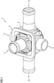
- Fig.1 Fig. 12 illustrates a multi-way cooling water valve 2 - also called cooling water control valve or cooling water control valve - for use in a cooling water valve unit - also called cooling water control valve unit - provided as such for use in a cooling water circuit of a vehicle.
- the cooling water valve unit also comprises an actuator unit (not shown here) for controlling a pivotably adjustable valve body 18 arranged between the valve housing 4 and the valve housing cover 6 (see, for example, FIGS Fig.2 ), via which a desired flow of cooling water between the individual ports 8, 10, 12, 14, 16 is adjustable.
- the multi-way cooling water valve 2 can act as a mixing valve and / or distribution valve, for example.
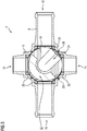
- Fig.2 illustrates a first position of the valve body 18 in which on the one hand a first flow of cooling water between the terminals 10, 12, 16 and a passage 22 in the partially spherical valve body 18 is made possible, and on the other hand, a second cooling water flow between the terminals 8, 14 and via a further passage 24 of the valve body 18.
- a seal 20 is provided in each case depending on a closed position of the valve body 18, in which the respective terminal 10, 12, 14, 16 close and seal, on the one hand against the valve body 18 acts static sealing and on the other hand acts against the valve housing 4 dynamic sealing.
- the distinction described above between a dynamic and static sealing effect is applied analogously. For completeness, it should be noted at this point that the valve body 18 is not in any of the figure representations with respect to any of the seals 20 in a closed position. Consequently, none of these ports 10, 12, 14, 16 is fully closed and thus sealed.
- valve body 18 is in relation to the two lower sealing portions 28 of a further seal 26 (see Figure 6 ) - which for dividing a valve chamber, which is formed by the valve housing 6 and the valve body 18, between two adjacent terminals 12, 14, 16 is provided - in an activating or closing position, in which the valve body 18 with the two sealing portions 28th cooperates while the valve chamber between the adjacent terminals 12, 14 on the one hand and the adjacent terminals 14, 16 on the other hand divided into a first valve chamber VK I and a second valve chamber VK II (see also Figure 9 ).
- valve body 18 is in an activating or closing position with respect to the upper right and left lower seal sections 28, in which a first flow of cooling water between the ports 10, 16 and via the passage 22 and on the other hand a second flow of cooling water between the ports 8, 12, 14 and via the passage 24 as desired.
- valve body 18 in a relation to the Figure 3 pivoted by 90 ° counterclockwise position.
- the valve body 18 is in an activating or closing position with respect to the upper left and right lower seal sections 28, in which on the one hand a first flow of cooling water between the connections 14, 16 and via the passage 22 and on the other hand a second flow of cooling water between the two Ports 8, 10, 12 and on the passage 24 as desired comes about.
- Figure 6 illustrates a first part of a multi-piece seal 26, which as such has four individual seal portions 28. These sealing portions 28 are formed via a respective web portion 30 on an annular connecting portion 32. The sealing portions 28, the web portions 30 and the connecting portion 32 thereby form an integral or one-piece sealing part, which is injection-molded from a plastic.
- the seal 26 continues to include - albeit only partially in Figure 7 shown -, second part.
- the first and second part of the seal 26 are formed for example as equal parts. Basically, it does not have to be the same thing.
- the illustrated embodiment of the first and second sealing part see. Figure 6 & Figure 7 ) only by way of example.
- the spatial extent of the seal 26 may vary depending on the application. This opens up a correspondingly large margin for a person skilled in the spatial design of such a seal.
- the first and second part of the seal 26 are connected to each other at the free ends of their respective sealing portions 28 via a respective connecting piece 44 (see. Figure 7 ).
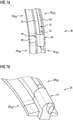
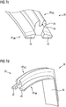
- Figure 7 includes the Fig.7a, Fig.7b . 7c and 7d , In 7a two adjacent sealing portions 28 are shown, which are interconnected by means of the connecting piece 44.
- the two sealing sections 28 in this case each comprise on the valve housing side an elastically deformable anchoring section 28 VG in the form of two spring-like anchoring elements 34 which are elastically spaced or deformable relative to one another and form a groove 36 extending in a longitudinal direction of the respective sealing section 28.
- the connecting piece 44 adjoins the shaping of the two sealing sections 28 in a form-fitting and flush manner.
- a pin 50 formed at the two ends of the connecting piece 44, which extends into the respective associated groove 36.
- the sealing portion 28 has valve body side on a flange-shaped portion 28 VK , which is formed corresponding to the partially spherical contour of the valve body 18.
- the valve body may be formed, for example, cylindrical and / or spherical.
- the central region of the end 38 to be joined of the sealing section 28 is set back slightly relative to the two flanking flange sections 42.
- connecting piece 44 is designed in the longitudinal direction at its two ends correspondingly complementary to the respective end 38 in order, as described above, to connect in a form-fitting and flush manner to the shape of the respective sealing section 28.
- the two flanking flange portions 46 are slightly set back relative to the central region 48 of the connecting piece 44.
- the individual connectors 44 also be integrally formed or integrally with each other.
- the flange portions 46 correspondingly extended or circumferential, ie extending from the connecting piece 44 to the connecting piece 44.
- valve housing 6 in addition to the valve housing cover 4 and the interposed valve body 18.
- the valve body 18 is in an activating or closing position, in which it cooperates with the two sealing portions 28 and the connecting piece 44 and thereby the valve chamber formed by the valve housing 6 and the valve body 18 between two adjacent terminals 10, 12, 14, 16 of the fluid valve 2, according to the foregoing description, into a first valve chamber VK I and a second valve chamber VK II divided (see also Figure 9 ).
- the two spring-like anchoring elements 34 are inserted by clamping in a groove-shaped valve housing recess 7 and thereby elastically deformed. In the region of their abutment against the valve housing recess 7, these two anchoring elements 34 each have a valve housing side, convex bulge or convex bulge 35, via which a clamping force is generated and which as such linear and / or planar and thereby dynamically sealing with the Valve housing recess 7 cooperates. In the longitudinal direction Y - Y or in a radial direction Y - Y with respect to the spherical valve body section 18, the two anchoring elements 34 are sufficiently spaced from the valve housing recess 7 (cf.
- FIG 9 Distance 37) and form with the valve housing recess 7 a gap 9 (see. Figure 9 ).
- a pressurized cooling water which penetrates into this intermediate space 9 can move the sealing section 28 in the radial direction Y - Y counteract advantageously and at the same time support the line-like and / or planar, statically sealing contact of the flange-like portion 28 VK against the valve body 18. That is to say that the cooling water can also advantageously have a force-boosting effect with respect to the clamping force between the respective bulge 35 and the valve housing recess 7.
- the flange portion 28 VK is, for example, isosceles and formed with inclined inner surfaces 40. Alternatively, the flange portion 28 VK could also be formed with parallel inner surfaces.
- FIG 10 an alternative embodiment with respect to the sealing portion 28 can be seen, in which the two spring-like anchoring elements 34 in comparison to Figure 9 are designed narrower.
- the anchoring elements 34 each have a housing-side, convex bulge 35 in the region of their two upper ends.
- the flange portion 28 VK is also isosceles and formed with inclined inner surfaces 40 (see inclination angle X °).
- this embodiment has rounded edges and transitions.
- the first and second sealing part can preferably be injection-molded from a hard plastic.
- a hard plastic can be understood to mean a plastic which, as such, is linearly and / or laminarly tight at the respective sealing contact point and which does not deform elastically or at least as well as not elastically when interacting with the valve body 18.
- a plastic is e.g. PTFE (PTFE stands for polytetrafluoroethylene) and the like.
- the connecting pieces 44 may be injection-molded from a softer plastic-such as an EPDM plastic (EPDM stands for ethylene-propylene-diene) and the like-which can be elastically deformed as such when interacting with the valve body 18.
- EPDM ethylene-propylene-diene
- the connecting piece 44 also acts as a compensation element.
Landscapes
- Engineering & Computer Science (AREA)
- General Engineering & Computer Science (AREA)
- Mechanical Engineering (AREA)
- Valve Housings (AREA)
Abstract
Description
- Die vorliegende Erfindung betrifft eine Dichtung, eine Dichtungsanordnung mit einer solchen Dichtung und ein Mehrwege--Fluidventil mit einer solchen Dichtungsanordnung. Die Dichtung ist dabei zur Verwendung in einem Fluidventil, insbesondere in Gestalt eines Mehrwege-Kühlwasserventils, insbesondere eines Fahrzeugs vorgesehen.
- Unter einem Fahrzeug ist dabei jede Art von Fahrzeug zu verstehen, welches zum Betrieb mit einem flüssigen und/oder gasförmigen Kraftstoff versorgt werden muss, insbesondere aber Personenkraftwagen und/oder Nutzfahrzeuge. Ferner kann es sich beim Fahrzeug auch um ein teilelektrisches oder vollelektrisches Fahrzeug handeln, insbesondere aber um Personenkraftwagen und/oder Nutzfahrzeuge.
- Dichtungen als solche können unterschiedliche Aufgaben haben. Sie können z.B. dem Zweck dienen, ungewollte Fluidverluste zu vermeiden oder zumindest zu begrenzen. Unter einem Fluid kann dabei ein flüssiges und/oder gasförmiges Medium verstanden werden.
- Aufgabe der vorliegenden Erfindung ist es, eine Dichtung bereitzustellen, mit der sich innerhalb eines Fluidventils bedarfsweise voneinander unabhängige Fluidflüsse einstellen lassen. Des Weiteren ist es eine Aufgabe der Erfindung, ein Fluidventil mit einer solchen Dichtung bereitzustellen. Die Dichtung soll dabei ferner kostengünstig herstellbar sein.
- Diese Aufgabe wird durch den Anspruch 1 gelöst, der eine Dichtung zur Verwendung in einem Fluidventil unter Schutz stellt. Es wird ferner eine Dichtungsanordnung unter Schutz gestellt (vgl. Anspruch 11), die eine solche Dichtung umfasst. Ferner wird ein Fluidventil in Gestalt eines Mehrwege-Fluidventils vorgeschlagen (vgl. Anspruch 12). Des Weiteren wird eine Verwendung der Dichtung in einem Fluidventil, insbesondere in Gestalt eines Mehrwege-Fluidventils vorgeschlagen (vgl. Anspruch 13). Vorteilhafte Ausführungsformen der Erfindung sind Gegenstand der Unteransprüche.
- Die vorgeschlagene Dichtung ist zur Verwendung in einem Fluidventil und zur Unterteilung einer Ventilkammer zwischen zwei benachbarten Anschlüssen des Fluidventils vorgesehen, in welcher ein stellbarer Ventilkörper des Fluidventils angeordnet. Die Ventilkammer wird dabei durch die Dichtung abhängig von einer Stellung des Ventilkörpers in eine erste Ventilkammer und eine zweite Ventilkammer unterteilt, um einen Fluss eines Fluides zwischen der ersten Ventilkammer und der zweiten Ventilkammer abhängig von der Stellung des Ventilkörpers zu unterbinden.
- Die Dichtung weist dabei einen ventilgehäuseseitigen, elastisch verformbaren Verankerungsabschnitt zum Einstecken in eine nutförmige Ventilgehäuseaussparung und zur dynamisch dichtenden Anlage gegen die Ventilgehäuseaussparung auf sowie einen ventilkörperseitigen Abschnitt zur statisch dichtenden Anlage gegen den Ventilkörper.
- Dynamisch dichtwirkend bedeutet dabei, dass je nach sich im Fluidventil einstellenden fluidischen bzw. hydraulischen Druckbedingungen eine Relativbewegung zwischen dem abdichtenden Verankerungsabschnitt und der Ventilgehäuseaussparung entstehen kann. Statisch dichtwirkend hingegen bedeutet dabei, dass der ventilkörperseitige Abschnitt der Dichtung bei der Abdichtung gegenüber dem Ventilkörper feststeht und somit keine Relativbewegung entsteht.
- Der Verankerungsabschnitt der Dichtung kann dabei z.B. zwei federartige Verankerungselemente umfassen, welche zueinander elastisch beabstandbar sind und eine sich in einer Längsrichtung der Dichtung erstreckende Nut bilden. Diese beiden elastisch verformbaren Verankerungselemente verleihen der Dichtung eine für das Zusammenwirken mit der Ventilgehäuseaussparung notwendige Elastizität bzw. Verformbarkeit. Die beiden Verankerungselemente weisen ferner im Bereich ihrer Anlage gegen die Ventilgehäuseaussparung jeweils eine ventilgehäuseseitige, konvexe Auswölbung auf, die als solche linienartig und/oder flächenartig dichtend mit der Ventilgehäuseaussparung zusammenwirkt.
- Der ventilkörperseitige Abschnitt der Dichtung hingegen ist flanschartig ausgebildet, wobei der Flansch ventilkörperseitig korrespondierend zur jeweiligen Kontur des stellbaren Ventilkörpers ausgeformt ist. Der Ventilkörper kann dabei z.B. zylinderförmig und/oder kugelförmig ausgebildet sein. Grundsätzlich ist die Kontur des Ventilkörpers beliebig gestaltbar. Der Flansch kann ferner gleichschenklig, mit parallelen Innenflächen, mit geneigten Innenflächen und/oder mit gerundeten Kanten und Übergängen ausgebildet sein.
- Die vorgeschlagene Dichtung kann z.B. ein- oder mehrteilig ausgebildet sein. Im letzteren Fall sind zwei benachbarte Dichtungsabschnitte über ein Verbindungstück miteinander verbunden.
- Die vorgeschlagene Dichtungsanordnung umfasst:
- ein Ventilgehäuse eines Fluidventils
- einen stellbaren Ventilkörper innerhalb des Ventilgehäuses sowie
- eine Dichtung der zuvor beschriebenen Art,
- Das vorgeschlagene Mehrwege-Fluidventil umfasst die zuvor beschriebene Dichtungsanordnung. Durch die Dichtung lässt sich dabei vorteilhafterweise abhängig von einer Stellung des Ventilkörpers einerseits ein gewünschter Fluss eines Fluides zwischen den Anschlüssen des Fluidventils herstellen und andererseits ein Fluss des Fluides zwischen der ersten Ventilkammer und der zweiten Ventilkammer unterbunden. Das Mehrwege-Fluidventil kann dabei als Mischventil und/oder Verteilerventil fungieren.
- Bei der vorgeschlagenen Verwendung der Dichtung kann das Fluidventil als Kühlwasserventil, insbesondere eines Fahrzeugs verwendet werden.
- Im Weiteren wird die Erfindung unter Bezugnahme auf Figurendarstellungen im Einzelnen erläutert. Aus den Unteransprüchen und der nachfolgend detaillierten Beschreibung von vorgeschlagenen Ausführungsformen ergeben sich weitere vorteilhafte Weiterbildungen der Erfindung. Hierzu zeigen:
- Fig.1
- ein Beispiel für ein Mehrwege-Fluidventil in einer perspektivischen Ansicht,
- Fig.2
- das in
Fig.1 gezeigte Mehrwege-Fluidventil in einer ersten Schnittdarstellung, - Fig.3
- das in
Fig.1 gezeigte Mehrwege-Fluidventil in einer zweiten Schnittdarstellung, - Fig.4
- das in
Fig.1 gezeigte Mehrwege-Fluidventil in einer dritten Schnittdarstellung, - Fig.5
- die in
Fig.4 gezeigte Schnittdarstellung in einer perspektivischen Ansicht, - Fig.6
- ein erstes Dichtungsteil in einer perspektivischen Ansicht,
- Fig.7a
- eine Verbindung zweier benachbarter Dichtungsabschnitte mittels eines Verbindungstücks in einer perspektivischen Ansicht,
- Fig.7b
- eine vergrößerte Darstellung des in
Fig.7a gezeigten oberen Dichtungsabschnitts und des Verbindungstücks, - Fig.7c
- eine vergrößerte Darstellung des in
Fig.7b gezeigten Dichtungsabschnitts ohne das Verbindungstück, - Fig.7d
- einen Abschnitt des in
Fig.6 gezeigten Dichtungsteils. - Fig.8
- eine Schnittdarstellung einer Dichtungsanordnung mit der in
Fig.7a gezeigten Verbindungsanordnung, - Fig.9
- eine weitere Schnittdarstellung der in
Fig.8 gezeigten Dichtungsanordnung sowie - Fig.10
- eine Schnittdarstellung einer alternativen Dichtungsanordnung.
- Gleiche oder gleichwirkende Merkmale sind über alle Figuren hinweg mit denselben Bezugszeichen gekennzeichnet.
-
Fig.1 veranschaulicht ein Mehrwege-Kühlwasserventil 2 - auch Kühlwassersteuerventil oder Kühlwasserregelventil genannt - zur Verwendung in einer Kühlwasserventileinheit - auch Kühlwassersteuerventileinheit genannt -, die als solche zur Verwendung in einem Kühlwasserkreislauf eines Fahrzeugs vorgesehen ist. Die Kühlwasserventileinheit umfasst dabei neben dem Mehrwege-Kühlwasserventil 2 auch eine - hier nicht dargestellte - Aktuatoreinheit zur Steuerung eines zwischen dem Ventilgehäuse 4 und dem Ventilgehäusedeckel 6 angeordneten, verschwenkbar stellbaren Ventilkörpers 18 (siehe dazu z.B.Fig.2 ), über welchen ein gewünschter Kühlwasserfluss zwischen den einzelnen Anschlüssen 8, 10, 12, 14, 16 einstellbar ist. Das Mehrwege-Kühlwasserventil 2 kann dabei z.B. als Mischventil und/oder Verteilerventil fungieren. -
Fig.2 veranschaulicht eine erste Stellung des Ventilkörpers 18, in welcher einerseits ein erster Kühlwasserfluss zwischen den Anschlüssen 10, 12, 16 und über einen Durchlass 22 im abschnittsweise kugelförmig ausgebildeten Ventilkörper 18 ermöglicht wird, und andererseits ein zweiter Kühlwasserfluss zwischen den Anschlüssen 8, 14 und über einen weiteren Durchlass 24 des Ventilkörpers 18. Zwischen den Anschlüssen 10, 12, 14, 16 und dem Ventilkörper 18 ist jeweils eine Dichtung 20 vorgesehen, die abhängig von einer Schließstellung des Ventilkörpers 18, in welcher der jeweilige Anschluss 10, 12, 14, 16 zu schließen und abzudichten ist, einerseits gegenüber dem Ventilkörper 18 statisch dichtend wirkt und andererseits gegenüber dem Ventilgehäuse 4 dynamisch dichtend wirkt. Die eingangs beschriebene Unterscheidung zwischen einer dynamischen und statischen Dichtwirkung ist dabei analog anzuwenden. Der Vollständigkeit halber sei an dieser Stelle angemerkt, dass sich der Ventilkörper 18 in keiner der Figurendarstellungen in Bezug auf irgendeine der Dichtungen 20 in einer Schließstellung befindet. Folglich ist keiner dieser Anschlüsse 10, 12, 14, 16 vollständig geschlossen und somit abgedichtet dargestellt. - In der
Fig.2 befindet sich der Ventilkörper 18 aber in Bezug auf die beiden unteren Dichtungsabschnitte 28 einer weiteren Dichtung 26 (vgl. dazuFig.6 ) - welche zur Unterteilung einer Ventilkammer, die durch das Ventilgehäuse 6 und den Ventilkörper 18 gebildet wird, zwischen zwei benachbarten Anschlüssen 12, 14, 16 vorgesehen ist - in einer aktivierenden bzw. schließenden Stellung, in welcher der Ventilkörper 18 mit den beiden Dichtungsabschnitten 28 zusammenwirkt und dabei die Ventilkammer zwischen den benachbarten Anschlüssen 12, 14 einerseits und den benachbarten Anschlüssen 14, 16 andererseits in eine erste Ventilkammer VKI und eine zweite Ventilkammer VKII unterteilt (vgl. dazu auchFig.9 ). In dieser ersten Stellung des Ventilkörpers 18 kommt der zuvor beschriebene erste Kühlwasserfluss zwischen den Anschlüssen 10, 12, 16 und über den Durchlass 22 einerseits und der zweite Kühlwasserfluss zwischen den Anschlüssen 8, 14 und über den Durchlass 24 andererseits zustande, ohne dass sich die beiden Kühlwasserflüsse miteinander vermengen. Der Kühlwasserfluss zwischen diesen beiden Ventilkammern VKI, VKII ist vielmehr durch eine Aktivierung der jeweiligen Dichtungsabschnitte 28 infolge des Zusammenwirkens mit dem Ventilkörper 18 wunschgemäß gänzlich unterbunden. - In der
Fig.3 befindet sich der Ventilkörper 18 in Bezug auf den rechten oberen und den linken unteren Dichtungsabschnitt 28 in einer aktivierenden bzw. schließenden Stellung, in welcher einerseits ein erster Kühlwasserfluss zwischen den Anschlüssen 10, 16 und über den Durchlass 22 und andererseits ein zweiter Kühlwasserfluss zwischen den Anschlüssen 8, 12, 14 und über den Durchlass 24 wunschgemäß zustande kommt. - In der
Fig.4 undFig.5 befindet sich der Ventilkörper 18 in einer gegenüber derFig.3 um 90° gegen den Uhrzeigersinn verschwenkten Stellung. Dabei befindet sich der Ventilkörper 18 in Bezug auf den linken oberen und den rechten unteren Dichtungsabschnitt 28 in einer aktivierenden bzw. schließenden Stellung, in welcher einerseits ein erster Kühlwasserfluss zwischen den Anschlüssen 14, 16 und über den Durchlass 22 und andererseits ein zweiter Kühlwasserfluss zwischen den Anschlüssen 8, 10, 12 und über den Durchlass 24 wunschgemäß zustande kommt. -
Fig.6 veranschaulicht einen ersten Teil einer mehrteiligen Dichtung 26, der als solcher vier einzelne Dichtungsabschnitte 28 aufweist. Diese Dichtungsabschnitte 28 sind dabei über je einen Stegabschnitt 30 an einem kreisringförmigen Verbindungsabschnitt 32 angeformt. Die Dichtungsabschnitte 28, die Stegabschnitte 30 sowie der Verbindungsabschnitt 32 bilden dabei ein einstückiges bzw. einteiliges Dichtungsteil, welches aus einem Kunststoff gespritzt ist. - Zur Dichtung 26 gehört weiterhin ein - wenn auch nur teilweise in
Fig.7 dargestellter -, zweiter Teil. Der erste und zweite Teil der Dichtung 26 sind dabei z.B. als Gleichteile ausgebildet. Grundsätzlich muss es sich dabei aber nicht um Gleichteile handeln. Auch ist die gezeigte Ausbildung des ersten und zweiten Dichtungsteils (vgl.Fig.6 &Fig.7 ) nur beispielhaft zu verstehen. Die räumliche Erstreckung der Dichtung 26 kann je nach Anwendungsfall unterschiedlich ausfallen. Somit eröffnet sich für einen Fachmann ein entsprechend großer Spielraum bei der räumlichen Ausgestaltung einer solchen Dichtung. - Der erste und zweite Teil der Dichtung 26 sind dabei an den freien Enden ihrer jeweiligen Dichtungsabschnitte 28 über je ein Verbindungsstück 44 miteinander verbunden (vgl.
Fig.7 ). -
Fig.7 umfasst dieFig.7a, Fig.7b ,Fig.7c und Fig.7d . InFig.7a sind zwei benachbarte Dichtungsabschnitte 28 gezeigt, die mittels des Verbindungsstücks 44 miteinander verbunden sind. Die beiden Dichtungsabschnitte 28 umfassen dabei ventilgehäuseseitig jeweils einen elastisch verformbaren Verankerungsabschnitt 28VG in Gestalt zweier federartiger Verankerungselemente 34, welche zueinander elastisch beabstandbar bzw. verformbar sind und eine sich in einer Längsrichtung des jeweiligen Dichtungsabschnitts 28 erstreckende Nut 36 bilden. Das Verbindungsstück 44 schließt sich dabei formschlüssig und bündig an die Formgebung der beiden Dichtungsabschnitte 28 an. In der besagten Längsrichtung ist an den beiden Enden des Verbindungsstücks 44 jeweils ein Zapfen 50 angeformt, der sich in die jeweils zugeordnete Nut 36 erstreckt. Der Dichtungsabschnitt 28 weist ventilkörperseitig einen flanschartig ausgebildeten Abschnitt 28VK auf, welcher korrespondierend zur abschnittsweise kugelförmigen Kontur des Ventilkörpers 18 ausgeformt ist. Grundsätzlich kann der Ventilkörper z.B. zylinderförmig und/oder kugelförmig ausgebildet sein. InFig.7c ist ferner zu erkennen, dass der mittlere Bereich des zu fügenden Endes 38 des Dichtungsabschnitts 28 gegenüber den beiden flankierenden Flanschabschnitten 42 geringfügig zurückgesetzt ist. Das Verbindungsstück 44 hingegen ist in der besagten Längsrichtung an seinen beiden Enden entsprechend komplementär zum jeweiligen Ende 38 ausgebildet, um sich - wie zuvor beschrieben - entsprechend formschlüssig und bündig an die Formgebung des jeweiligen Dichtungsabschnitts 28 anzuschließen. Dabei sind die beiden flankierenden Flanschabschnitte 46 gegenüber dem mittleren Bereich 48 des Verbindungsstücks 44 geringfügig zurückgesetzt. - Alternativ zur Darstellung in
Fig.7 könnten die einzelnen Verbindungsstücke 44 auch einstückig bzw. einteilig miteinander ausgeformt sein. Dazu stelle man sich die Flanschabschnitte 46 entsprechend verlängert bzw. umlaufend vor, d.h. sich von Verbindungsstück 44 zu Verbindungstück 44 erstreckend. - Die Dichtungsanordnung nach
Fig.8 zeigt das Ventilgehäuse 6 nebst dem Ventilgehäusedeckel 4 und den dazwischen angeordneten Ventilkörper 18. Zwischen dem Ventilgehäuse 6 und dem Ventilkörper 18 befinden sich zwei benachbarte Dichtungsabschnitte 28, die über das Verbindungsstück 44 miteinander verbunden sind. Der Ventilkörper 18 befindet sich dabei in einer aktivierenden bzw. schließenden Stellung, in welcher er mit den beiden Dichtungsabschnitten 28 und dem Verbindungsstück 44 zusammenwirkt und dabei die durch das Ventilgehäuse 6 und den Ventilkörper 18 gebildete Ventilkammer zwischen zwei benachbarten Anschlüssen 10, 12, 14, 16 des Fluidventils 2, entsprechend der vorhergehenden Beschreibung, in eine erste Ventilkammer VKI und eine zweite Ventilkammer VKII unterteilt (vgl. dazu auchFig.9 ). - Die zwei federartigen Verankerungselemente 34 sind in eine nutförmige Ventilgehäuseaussparung 7 klemmend eingesteckt und dabei elastisch verformt. Im Bereich ihrer Anlage gegen die Ventilgehäuseaussparung 7 weisen diese beiden Verankerungselemente 34 jeweils eine ventilgehäuseseitige, konvexe Ausbauchung bzw. konvexe Auswölbung 35 auf, über welche eine Klemmkraft erzeugt wird und welche als solche linienartig und/oder flächenartig und dabei dynamisch dichtend mit der Ventilgehäuseaussparung 7 zusammenwirkt. In der Längsrichtung Y - Y bzw. in einer bezüglich des kugelförmigen Ventilkörperabschnitts 18 radialen Richtung Y - Y sind die beiden Verankerungselemente 34 gegenüber der Ventilgehäuseaussparung 7 hinreichend beabstandet (vgl.
Fig.9 , Abstand 37) und bilden mit der Ventilgehäuseaussparung 7 einen Zwischenraum 9 (vgl.Fig.9 ). Je nach den sich in den beiden Ventilkammern VKI, VKII darstellenden Druckbedingungen bzw. Druckverhältnissen pI, pII, kann ein unter Druck stehendes Kühlwasser, welches in diesen Zwischenraum 9 eindringt, einer Bewegung des Dichtungsabschnitts 28 in der radialer Richtung Y - Y vorteilhafterweise entgegenwirken und dabei zugleich die linienartige und/oder flächenartige, statisch dichtende Anlage des flanschartigen Abschnitts 28VK gegen den Ventilkörper 18 unterstützen. D.h., dass das Kühlwasser zudem vorteilhafterweise kraftverstärkend in Bezug auf die Klemmkraft zwischen der jeweiligen Auswölbung 35 und der Ventilgehäuseaussparung 7 wirken kann. Der Flanschabschnitt 28VK ist dabei z.B. gleichschenklig und mit geneigten Innenflächen 40 ausgebildet. Alternativ dazu ließe sich der Flanschabschnitt 28VK auch mit parallelen Innenflächen ausbilden. - In
Fig.10 ist eine alternative Ausgestaltung in Bezug auf den Dichtungsabschnitt 28 zu sehen, bei der die beiden federartigen Verankerungselemente 34 im Vergleich zurFig.9 schmaler ausgestaltet sind. Die Verankerungselemente 34 weisen dabei im Bereich ihrer beiden oberen Enden jeweils eine gehäuseseitige, konvexe Auswölbung 35 auf. Der Flanschabschnitt 28VK ist dabei ebenfalls gleichschenklig und mit geneigten Innenflächen 40 ausgebildet (vgl. Neigungswinkel X°). Gegenüber derFig.9 weist diese Ausgestaltung allerdings gerundete Kanten und Übergänge auf. - Bei genauerer Betrachtung ist in den
Figuren 9 und10 eine geringfügige Überschneidung zwischen den jeweiligen Auswölbungen 35 und der jeweiligen Ventilgehäuseaussparung 7 zu erkennen. Dies ist eine bewusst dargestellte Überzeichnung, die als solche durch eine entsprechend elastische Verformung der jeweiligen Verankerungselemente 34 auszugleichen ist. Die resultierende elastische Verformung muss sich der Leser dabei vorstellen. - Allen vorhergehenden Ausführungen zur Dichtung 26 ist gemein, dass das erste und zweite Dichtungsteil vorzugsweise aus einem Hart-Kunststoff gespritzt sein können. Unter einem Hart-Kunststoff kann dabei ein Kunststoff verstanden werden, der als solcher an der jeweils dichtenden Kontaktstelle linienartig und/oder flächenartig dichtwirkend ist und der sich beim Zusammenwirken mit dem Ventilkörper 18 elastisch nicht oder zumindest so gut wie nicht elastisch verformen lässt. Ein solcher Kunststoff ist z.B. PTFE (PTFE steht dabei für Polytetrafluorethylen) und dergleichen mehr.
- Die Verbindungsstücke 44 hingegen können aus einem weicheren Kunststoff - etwa aus einem EPDM-Kunststoff (EPDM steht dabei für Ethylen-Propylen-Dien) und dergleichen mehr - gespritzt sein, der sich als solcher beim Zusammenwirken mit dem Ventilkörper 18 elastisch verformen lässt. In Verbindung mit den zuvor genannten Hart-Kunststoff-Dichtungsteilen fungiert ein solches Verbindungsstück 44 zudem als Ausgleichselement.
- Obwohl in der vorhergehenden Beschreibung exemplarische Ausführungen erläutert wurden, sei darauf hingewiesen, dass eine Vielzahl von Abwandlungen möglich ist. Außerdem sei darauf hingewiesen, dass es sich bei den exemplarischen Ausführungen lediglich um Beispiele handelt, die den Schutzbereich, die Anwendungen und den Aufbau in keiner Weise einschränken sollen. Vielmehr wird dem Fachmann durch die vorausgehende Beschreibung ein Leitfaden für die Umsetzung von mindestens einer exemplarischen Ausführung gegeben, wobei diverse Änderungen, insbesondere in Hinblick auf die Funktion und Anordnung der beschriebenen Bestandteile, vorgenommen werden können, ohne den Schutzbereich zu verlassen, wie er sich aus den Ansprüchen und diesen äquivalenten Merkmalskombinationen ergibt.
Claims (14)
- Dichtung zur Verwendung in einem Fluidventil (2) und zur Unterteilung einer Ventilkammer zwischen zwei benachbarten Anschlüssen (10, 12, 14, 16) des Fluidventils (2), in welcher ein stellbarer Ventilkörper (18) des Fluidventils (2) angeordnet ist, in eine erste Ventilkammer (VKI) und eine zweite Ventilkammer (VKII), und zwar abhängig von einer Stellung des Ventilkörpers (18), um einen Fluss eines Fluides zwischen der ersten Ventilkammer (VKI) und der zweiten Ventilkammer (VKII) abhängig von der Stellung des Ventilkörpers (18) zu unterbinden, wobei die Dichtung (26, 28) einen ventilgehäuseseitigen, elastisch verformbaren Verankerungsabschnitt (28VG) zum Einstecken in eine nutförmige Ventilgehäuseaussparung (7) und zur dynamisch dichtenden Anlage gegen die Ventilgehäuseaussparung (7) aufweist sowie einen ventilkörperseitigen Abschnitt (28VK) zur statisch dichtenden Anlage gegen den Ventilkörper (18) .
- Dichtung nach Anspruch 1, wobei der Verankerungsabschnitt (28VG) zwei federartige Verankerungselemente (34) umfasst, welche zueinander elastisch beabstandbar sind und eine sich in einer Längsrichtung (Z - Z) der Dichtung (26, 28) erstreckende Nut (36) bilden.
- Dichtung nach Anspruch 1 oder 2, wobei die beiden Verankerungselemente (34) im Bereich ihrer Anlage gegen die Ventilgehäuseaussparung (7) jeweils eine ventilgehäuseseitige, konvexe Auswölbung (35) aufweisen.
- Dichtung nach einem der Ansprüche 1 bis 3, wobei der ventilkörperseitige Abschnitt (28VK) flanschartig ausgebildet ist, wobei der Flansch ventilkörperseitig korrespondierend zur jeweiligen Kontur des Ventilkörpers (18) ausgeformt ist.
- Dichtung nach Anspruch 4, wobei der Flansch gleichschenklig ausgebildet ist.
- Dichtung nach Anspruch 4 oder 5, wobei der Flansch mit parallelen Innenflächen (40) ausgebildet ist.
- Dichtung nach Anspruch 4, 5 oder 6, wobei der Flansch mit geneigten Innenflächen (40) ausgebildet ist.
- Dichtung nach einem der Ansprüche 4 bis 7, wobei der Flansch mit gerundeten Kanten und Übergängen ausgebildet ist.
- Dichtung nach einem der vorhergehenden Ansprüche, wobei die Dichtung (26, 28) einteilig oder mehrteilig ausgebildet ist.
- Dichtung nach Anspruch 9, wobei zwei benachbarte Dichtungsabschnitte (28) über ein Verbindungstück (44) miteinander verbunden sind.
- Dichtungsanordnung umfassend:• ein Ventilgehäuse (6) eines Fluidventils (2)• einen stellbaren Ventilkörper (18) innerhalb des Ventilgehäuses (6) sowie• eine Dichtung (26, 28) nach einem der Ansprüche 1 bis 10,wobei die Dichtung (26, 28) zwischen dem Ventilgehäuse (6) und dem Ventilkörper (18) angeordnet ist und eine durch das Ventilgehäuse (6) und den Ventilkörper (18) gebildete Ventilkammer zwischen zwei benachbarten Anschlüssen (10, 12, 14, 16) des Fluidventils (2) und abhängig von einer Stellung des Ventilkörpers (18) in eine erste Ventilkammer (VKI) und eine zweite Ventilkammer (VKII) unterteilt, um einen Fluss eines Fluides zwischen der ersten Ventilkammer (VKI) und der zweiten Ventilkammer (VKII) abhängig von der Stellung des Ventilkörpers (18) zu unterbinden.
- Mehrwege-Fluidventil mit einer Dichtungsanordnung nach Anspruch 11, bei dem durch die Dichtung (26, 28) abhängig von einer Stellung des Ventilkörpers (18) einerseits ein gewünschter Fluss eines Fluides zwischen den Anschlüssen (10, 12, 14, 16) des Mehrwege-Fluidventils (2) hergestellt ist und andererseits ein Fluss des Fluides zwischen der ersten Ventilkammer (VKI) und der zweiten Ventilkammer (VKII) unterbunden ist.
- Verwendung einer Dichtung nach einem der Ansprüche 1 bis 10 in einem Fluidventil (2).
- Verwendung nach Anspruch 13, wobei das Fluidventil (2) als Kühlwasserventil, insbesondere eines Fahrzeugs verwendet wird.
Priority Applications (2)
| Application Number | Priority Date | Filing Date | Title |
|---|---|---|---|
| EP18465518.1A EP3561346B1 (de) | 2018-04-24 | 2018-04-24 | Dichtung, dichtungsanordnung und mehrwege-fluidventil |
| PCT/EP2019/059799 WO2019206741A1 (de) | 2018-04-24 | 2019-04-16 | Dichtung, dichtungsanordnung und mehrwege-fluidventil |
Applications Claiming Priority (1)
| Application Number | Priority Date | Filing Date | Title |
|---|---|---|---|
| EP18465518.1A EP3561346B1 (de) | 2018-04-24 | 2018-04-24 | Dichtung, dichtungsanordnung und mehrwege-fluidventil |
Publications (2)
| Publication Number | Publication Date |
|---|---|
| EP3561346A1 true EP3561346A1 (de) | 2019-10-30 |
| EP3561346B1 EP3561346B1 (de) | 2022-06-08 |
Family
ID=62636135
Family Applications (1)
| Application Number | Title | Priority Date | Filing Date |
|---|---|---|---|
| EP18465518.1A Active EP3561346B1 (de) | 2018-04-24 | 2018-04-24 | Dichtung, dichtungsanordnung und mehrwege-fluidventil |
Country Status (2)
| Country | Link |
|---|---|
| EP (1) | EP3561346B1 (de) |
| WO (1) | WO2019206741A1 (de) |
Cited By (2)
| Publication number | Priority date | Publication date | Assignee | Title |
|---|---|---|---|---|
| EP3899329A4 (de) * | 2018-12-19 | 2022-09-14 | Robertshaw Controls Company | Multiport-ventil mit mehreren ebenen |
| EP3730821B1 (de) * | 2019-04-23 | 2023-07-05 | Vitesco Technologies GmbH | Mehrwegeventil |
Families Citing this family (2)
| Publication number | Priority date | Publication date | Assignee | Title |
|---|---|---|---|---|
| DE102020130487A1 (de) * | 2019-12-16 | 2021-06-17 | ECO Holding 1 GmbH | Vorrichtung zur Handhabung von Fluid innerhalb eines zumindest teilweise elektrisch angetriebenen Fahrzeugs |
| CN112855989B (zh) * | 2021-03-17 | 2024-10-29 | 烟台佳仕阀泵有限公司 | 一种偏心结构多通阀 |
Citations (6)
| Publication number | Priority date | Publication date | Assignee | Title |
|---|---|---|---|---|
| CA616199A (en) * | 1961-03-14 | E. Collins John | Annular packing member | |
| US4006882A (en) * | 1974-02-06 | 1977-02-08 | Applications Mecaniques Et Robinetterie Industrielle A.M.R.I. | Butterfly valve of large diameter |
| US4165859A (en) * | 1977-05-18 | 1979-08-28 | Crane Co. | Seal assembly |
| US6494466B1 (en) * | 2000-04-20 | 2002-12-17 | Thomas A. Hartman | Valve seal construction with non-congruent side serrations |
| DE10312801A1 (de) * | 2003-03-21 | 2004-09-30 | Waldemar Boras | Armatur |
| FR2987094A1 (fr) * | 2012-02-21 | 2013-08-23 | Ksb Sas | Robinet a papillon |
-
2018
- 2018-04-24 EP EP18465518.1A patent/EP3561346B1/de active Active
-
2019
- 2019-04-16 WO PCT/EP2019/059799 patent/WO2019206741A1/de not_active Ceased
Patent Citations (6)
| Publication number | Priority date | Publication date | Assignee | Title |
|---|---|---|---|---|
| CA616199A (en) * | 1961-03-14 | E. Collins John | Annular packing member | |
| US4006882A (en) * | 1974-02-06 | 1977-02-08 | Applications Mecaniques Et Robinetterie Industrielle A.M.R.I. | Butterfly valve of large diameter |
| US4165859A (en) * | 1977-05-18 | 1979-08-28 | Crane Co. | Seal assembly |
| US6494466B1 (en) * | 2000-04-20 | 2002-12-17 | Thomas A. Hartman | Valve seal construction with non-congruent side serrations |
| DE10312801A1 (de) * | 2003-03-21 | 2004-09-30 | Waldemar Boras | Armatur |
| FR2987094A1 (fr) * | 2012-02-21 | 2013-08-23 | Ksb Sas | Robinet a papillon |
Cited By (4)
| Publication number | Priority date | Publication date | Assignee | Title |
|---|---|---|---|---|
| EP3899329A4 (de) * | 2018-12-19 | 2022-09-14 | Robertshaw Controls Company | Multiport-ventil mit mehreren ebenen |
| US11655906B2 (en) | 2018-12-19 | 2023-05-23 | Robertshaw Controls Company | Multi-port multi-plane valve |
| EP3730821B1 (de) * | 2019-04-23 | 2023-07-05 | Vitesco Technologies GmbH | Mehrwegeventil |
| US11885255B2 (en) | 2019-04-23 | 2024-01-30 | Vitesco Technologies GmbH | Multiport valve |
Also Published As
| Publication number | Publication date |
|---|---|
| EP3561346B1 (de) | 2022-06-08 |
| WO2019206741A1 (de) | 2019-10-31 |
Similar Documents
| Publication | Publication Date | Title |
|---|---|---|
| EP3652831B1 (de) | Zugentlastungstülle | |
| EP3762637B1 (de) | Dichtungsanordnung und fluidregelventil | |
| EP3561346B1 (de) | Dichtung, dichtungsanordnung und mehrwege-fluidventil | |
| EP2467629A1 (de) | Federelastische axiale dichtung | |
| EP3004702B1 (de) | Kombination aus einem gehäuse und einem ventil | |
| EP3553355A1 (de) | Dichtung und fluidregelventil | |
| EP0912225A1 (de) | Scheibe, insbesondere stirnscheibe eines filtereinsatzes | |
| DE10310124B4 (de) | Flachdichtung | |
| DE102010016845A1 (de) | Prozessventil mit flexibler Dichtkante | |
| DE102018205557A1 (de) | Dichtungsanordnung und Fluidventil | |
| EP3824207B1 (de) | Hubventil und dichtung | |
| WO2016046064A1 (de) | Vorrichtung zur dichtung eines ventils | |
| DE102005003982A1 (de) | Pneumatisches Wegeventil mit einem Ventilschieber | |
| DE202022101886U1 (de) | Stellventil | |
| DE102016215154B4 (de) | Abdichtungssystem | |
| EP1738099B1 (de) | Steckverbindung mit einem formdichtring | |
| WO2019170735A1 (de) | Dichtungsanordnung und fluidregelventil | |
| EP1774217A1 (de) | Verbindung von leitungen für hochdruckmedien | |
| EP1520129B1 (de) | Schieberventil | |
| EP0283696B1 (de) | Elastomerdichtung | |
| EP0412997A1 (de) | Dichtungsanordnung. | |
| DE202006005269U1 (de) | Reifenventil, Ventilsystem und Reifen | |
| EP4022204B1 (de) | Dichtungsanordnung für ein fluidventil, fluidventil und fahrzeug | |
| WO2019206742A1 (de) | Dichtung und fluidventil | |
| DE102022119580B3 (de) | Dichtung, Dichtungsanordnung und Wasseraufbereitungsgerät, das die Dichtungsanordnung und die Dichtung umfasst |
Legal Events
| Date | Code | Title | Description |
|---|---|---|---|
| PUAI | Public reference made under article 153(3) epc to a published international application that has entered the european phase |
Free format text: ORIGINAL CODE: 0009012 |
|
| STAA | Information on the status of an ep patent application or granted ep patent |
Free format text: STATUS: THE APPLICATION HAS BEEN PUBLISHED |
|
| AK | Designated contracting states |
Kind code of ref document: A1 Designated state(s): AL AT BE BG CH CY CZ DE DK EE ES FI FR GB GR HR HU IE IS IT LI LT LU LV MC MK MT NL NO PL PT RO RS SE SI SK SM TR |
|
| AX | Request for extension of the european patent |
Extension state: BA ME |
|
| STAA | Information on the status of an ep patent application or granted ep patent |
Free format text: STATUS: REQUEST FOR EXAMINATION WAS MADE |
|
| RAP1 | Party data changed (applicant data changed or rights of an application transferred) |
Owner name: VITESCO TECHNOLOGIES GMBH |
|
| 17P | Request for examination filed |
Effective date: 20200430 |
|
| RBV | Designated contracting states (corrected) |
Designated state(s): AL AT BE BG CH CY CZ DE DK EE ES FI FR GB GR HR HU IE IS IT LI LT LU LV MC MK MT NL NO PL PT RO RS SE SI SK SM TR |
|
| STAA | Information on the status of an ep patent application or granted ep patent |
Free format text: STATUS: EXAMINATION IS IN PROGRESS |
|
| 17Q | First examination report despatched |
Effective date: 20200721 |
|
| RAP3 | Party data changed (applicant data changed or rights of an application transferred) |
Owner name: VITESCO TECHNOLOGIES GMBH |
|
| GRAP | Despatch of communication of intention to grant a patent |
Free format text: ORIGINAL CODE: EPIDOSNIGR1 |
|
| STAA | Information on the status of an ep patent application or granted ep patent |
Free format text: STATUS: GRANT OF PATENT IS INTENDED |
|
| INTG | Intention to grant announced |
Effective date: 20211208 |
|
| GRAS | Grant fee paid |
Free format text: ORIGINAL CODE: EPIDOSNIGR3 |
|
| GRAA | (expected) grant |
Free format text: ORIGINAL CODE: 0009210 |
|
| STAA | Information on the status of an ep patent application or granted ep patent |
Free format text: STATUS: THE PATENT HAS BEEN GRANTED |
|
| AK | Designated contracting states |
Kind code of ref document: B1 Designated state(s): AL AT BE BG CH CY CZ DE DK EE ES FI FR GB GR HR HU IE IS IT LI LT LU LV MC MK MT NL NO PL PT RO RS SE SI SK SM TR |
|
| REG | Reference to a national code |
Ref country code: AT Ref legal event code: REF Ref document number: 1497150 Country of ref document: AT Kind code of ref document: T Effective date: 20220615 Ref country code: CH Ref legal event code: EP |
|
| REG | Reference to a national code |
Ref country code: DE Ref legal event code: R096 Ref document number: 502018009858 Country of ref document: DE |
|
| REG | Reference to a national code |
Ref country code: IE Ref legal event code: FG4D Free format text: LANGUAGE OF EP DOCUMENT: GERMAN |
|
| REG | Reference to a national code |
Ref country code: LT Ref legal event code: MG9D |
|
| REG | Reference to a national code |
Ref country code: NL Ref legal event code: MP Effective date: 20220608 |
|
| PG25 | Lapsed in a contracting state [announced via postgrant information from national office to epo] |
Ref country code: SE Free format text: LAPSE BECAUSE OF FAILURE TO SUBMIT A TRANSLATION OF THE DESCRIPTION OR TO PAY THE FEE WITHIN THE PRESCRIBED TIME-LIMIT Effective date: 20220608 Ref country code: NO Free format text: LAPSE BECAUSE OF FAILURE TO SUBMIT A TRANSLATION OF THE DESCRIPTION OR TO PAY THE FEE WITHIN THE PRESCRIBED TIME-LIMIT Effective date: 20220908 Ref country code: LT Free format text: LAPSE BECAUSE OF FAILURE TO SUBMIT A TRANSLATION OF THE DESCRIPTION OR TO PAY THE FEE WITHIN THE PRESCRIBED TIME-LIMIT Effective date: 20220608 Ref country code: HR Free format text: LAPSE BECAUSE OF FAILURE TO SUBMIT A TRANSLATION OF THE DESCRIPTION OR TO PAY THE FEE WITHIN THE PRESCRIBED TIME-LIMIT Effective date: 20220608 Ref country code: GR Free format text: LAPSE BECAUSE OF FAILURE TO SUBMIT A TRANSLATION OF THE DESCRIPTION OR TO PAY THE FEE WITHIN THE PRESCRIBED TIME-LIMIT Effective date: 20220909 Ref country code: FI Free format text: LAPSE BECAUSE OF FAILURE TO SUBMIT A TRANSLATION OF THE DESCRIPTION OR TO PAY THE FEE WITHIN THE PRESCRIBED TIME-LIMIT Effective date: 20220608 Ref country code: ES Free format text: LAPSE BECAUSE OF FAILURE TO SUBMIT A TRANSLATION OF THE DESCRIPTION OR TO PAY THE FEE WITHIN THE PRESCRIBED TIME-LIMIT Effective date: 20220608 Ref country code: BG Free format text: LAPSE BECAUSE OF FAILURE TO SUBMIT A TRANSLATION OF THE DESCRIPTION OR TO PAY THE FEE WITHIN THE PRESCRIBED TIME-LIMIT Effective date: 20220908 |
|
| PG25 | Lapsed in a contracting state [announced via postgrant information from national office to epo] |
Ref country code: RS Free format text: LAPSE BECAUSE OF FAILURE TO SUBMIT A TRANSLATION OF THE DESCRIPTION OR TO PAY THE FEE WITHIN THE PRESCRIBED TIME-LIMIT Effective date: 20220608 Ref country code: LV Free format text: LAPSE BECAUSE OF FAILURE TO SUBMIT A TRANSLATION OF THE DESCRIPTION OR TO PAY THE FEE WITHIN THE PRESCRIBED TIME-LIMIT Effective date: 20220608 |
|
| PG25 | Lapsed in a contracting state [announced via postgrant information from national office to epo] |
Ref country code: NL Free format text: LAPSE BECAUSE OF FAILURE TO SUBMIT A TRANSLATION OF THE DESCRIPTION OR TO PAY THE FEE WITHIN THE PRESCRIBED TIME-LIMIT Effective date: 20220608 |
|
| PG25 | Lapsed in a contracting state [announced via postgrant information from national office to epo] |
Ref country code: SM Free format text: LAPSE BECAUSE OF FAILURE TO SUBMIT A TRANSLATION OF THE DESCRIPTION OR TO PAY THE FEE WITHIN THE PRESCRIBED TIME-LIMIT Effective date: 20220608 Ref country code: SK Free format text: LAPSE BECAUSE OF FAILURE TO SUBMIT A TRANSLATION OF THE DESCRIPTION OR TO PAY THE FEE WITHIN THE PRESCRIBED TIME-LIMIT Effective date: 20220608 Ref country code: RO Free format text: LAPSE BECAUSE OF FAILURE TO SUBMIT A TRANSLATION OF THE DESCRIPTION OR TO PAY THE FEE WITHIN THE PRESCRIBED TIME-LIMIT Effective date: 20220608 Ref country code: PT Free format text: LAPSE BECAUSE OF FAILURE TO SUBMIT A TRANSLATION OF THE DESCRIPTION OR TO PAY THE FEE WITHIN THE PRESCRIBED TIME-LIMIT Effective date: 20221010 Ref country code: EE Free format text: LAPSE BECAUSE OF FAILURE TO SUBMIT A TRANSLATION OF THE DESCRIPTION OR TO PAY THE FEE WITHIN THE PRESCRIBED TIME-LIMIT Effective date: 20220608 Ref country code: CZ Free format text: LAPSE BECAUSE OF FAILURE TO SUBMIT A TRANSLATION OF THE DESCRIPTION OR TO PAY THE FEE WITHIN THE PRESCRIBED TIME-LIMIT Effective date: 20220608 |
|
| PG25 | Lapsed in a contracting state [announced via postgrant information from national office to epo] |
Ref country code: PL Free format text: LAPSE BECAUSE OF FAILURE TO SUBMIT A TRANSLATION OF THE DESCRIPTION OR TO PAY THE FEE WITHIN THE PRESCRIBED TIME-LIMIT Effective date: 20220608 Ref country code: IS Free format text: LAPSE BECAUSE OF FAILURE TO SUBMIT A TRANSLATION OF THE DESCRIPTION OR TO PAY THE FEE WITHIN THE PRESCRIBED TIME-LIMIT Effective date: 20221008 |
|
| REG | Reference to a national code |
Ref country code: DE Ref legal event code: R097 Ref document number: 502018009858 Country of ref document: DE |
|
| PG25 | Lapsed in a contracting state [announced via postgrant information from national office to epo] |
Ref country code: AL Free format text: LAPSE BECAUSE OF FAILURE TO SUBMIT A TRANSLATION OF THE DESCRIPTION OR TO PAY THE FEE WITHIN THE PRESCRIBED TIME-LIMIT Effective date: 20220608 |
|
| PLBE | No opposition filed within time limit |
Free format text: ORIGINAL CODE: 0009261 |
|
| STAA | Information on the status of an ep patent application or granted ep patent |
Free format text: STATUS: NO OPPOSITION FILED WITHIN TIME LIMIT |
|
| PG25 | Lapsed in a contracting state [announced via postgrant information from national office to epo] |
Ref country code: DK Free format text: LAPSE BECAUSE OF FAILURE TO SUBMIT A TRANSLATION OF THE DESCRIPTION OR TO PAY THE FEE WITHIN THE PRESCRIBED TIME-LIMIT Effective date: 20220608 |
|
| 26N | No opposition filed |
Effective date: 20230310 |
|
| PG25 | Lapsed in a contracting state [announced via postgrant information from national office to epo] |
Ref country code: SI Free format text: LAPSE BECAUSE OF FAILURE TO SUBMIT A TRANSLATION OF THE DESCRIPTION OR TO PAY THE FEE WITHIN THE PRESCRIBED TIME-LIMIT Effective date: 20220608 |
|
| P01 | Opt-out of the competence of the unified patent court (upc) registered |
Effective date: 20230830 |
|
| REG | Reference to a national code |
Ref country code: CH Ref legal event code: PL |
|
| GBPC | Gb: european patent ceased through non-payment of renewal fee |
Effective date: 20230424 |
|
| PG25 | Lapsed in a contracting state [announced via postgrant information from national office to epo] |
Ref country code: LU Free format text: LAPSE BECAUSE OF NON-PAYMENT OF DUE FEES Effective date: 20230424 |
|
| REG | Reference to a national code |
Ref country code: BE Ref legal event code: MM Effective date: 20230430 |
|
| PG25 | Lapsed in a contracting state [announced via postgrant information from national office to epo] |
Ref country code: MC Free format text: LAPSE BECAUSE OF FAILURE TO SUBMIT A TRANSLATION OF THE DESCRIPTION OR TO PAY THE FEE WITHIN THE PRESCRIBED TIME-LIMIT Effective date: 20220608 |
|
| PG25 | Lapsed in a contracting state [announced via postgrant information from national office to epo] |
Ref country code: GB Free format text: LAPSE BECAUSE OF NON-PAYMENT OF DUE FEES Effective date: 20230424 |
|
| PG25 | Lapsed in a contracting state [announced via postgrant information from national office to epo] |
Ref country code: MC Free format text: LAPSE BECAUSE OF FAILURE TO SUBMIT A TRANSLATION OF THE DESCRIPTION OR TO PAY THE FEE WITHIN THE PRESCRIBED TIME-LIMIT Effective date: 20220608 Ref country code: LI Free format text: LAPSE BECAUSE OF NON-PAYMENT OF DUE FEES Effective date: 20230430 Ref country code: IT Free format text: LAPSE BECAUSE OF FAILURE TO SUBMIT A TRANSLATION OF THE DESCRIPTION OR TO PAY THE FEE WITHIN THE PRESCRIBED TIME-LIMIT Effective date: 20220608 Ref country code: GB Free format text: LAPSE BECAUSE OF NON-PAYMENT OF DUE FEES Effective date: 20230424 Ref country code: CH Free format text: LAPSE BECAUSE OF NON-PAYMENT OF DUE FEES Effective date: 20230430 |
|
| REG | Reference to a national code |
Ref country code: IE Ref legal event code: MM4A |
|
| PG25 | Lapsed in a contracting state [announced via postgrant information from national office to epo] |
Ref country code: BE Free format text: LAPSE BECAUSE OF NON-PAYMENT OF DUE FEES Effective date: 20230430 |
|
| PG25 | Lapsed in a contracting state [announced via postgrant information from national office to epo] |
Ref country code: IE Free format text: LAPSE BECAUSE OF NON-PAYMENT OF DUE FEES Effective date: 20230424 |
|
| PG25 | Lapsed in a contracting state [announced via postgrant information from national office to epo] |
Ref country code: IE Free format text: LAPSE BECAUSE OF NON-PAYMENT OF DUE FEES Effective date: 20230424 |
|
| REG | Reference to a national code |
Ref country code: AT Ref legal event code: MM01 Ref document number: 1497150 Country of ref document: AT Kind code of ref document: T Effective date: 20230424 |
|
| PG25 | Lapsed in a contracting state [announced via postgrant information from national office to epo] |
Ref country code: AT Free format text: LAPSE BECAUSE OF NON-PAYMENT OF DUE FEES Effective date: 20230424 |
|
| PG25 | Lapsed in a contracting state [announced via postgrant information from national office to epo] |
Ref country code: AT Free format text: LAPSE BECAUSE OF NON-PAYMENT OF DUE FEES Effective date: 20230424 |
|
| PG25 | Lapsed in a contracting state [announced via postgrant information from national office to epo] |
Ref country code: BG Free format text: LAPSE BECAUSE OF FAILURE TO SUBMIT A TRANSLATION OF THE DESCRIPTION OR TO PAY THE FEE WITHIN THE PRESCRIBED TIME-LIMIT Effective date: 20220608 |
|
| PG25 | Lapsed in a contracting state [announced via postgrant information from national office to epo] |
Ref country code: BG Free format text: LAPSE BECAUSE OF FAILURE TO SUBMIT A TRANSLATION OF THE DESCRIPTION OR TO PAY THE FEE WITHIN THE PRESCRIBED TIME-LIMIT Effective date: 20220608 |
|
| REG | Reference to a national code |
Ref country code: DE Ref legal event code: R081 Ref document number: 502018009858 Country of ref document: DE Owner name: SCHAEFFLER TECHNOLOGIES AG & CO. KG, DE Free format text: FORMER OWNER: VITESCO TECHNOLOGIES GMBH, 93055 REGENSBURG, DE |
|
| PGFP | Annual fee paid to national office [announced via postgrant information from national office to epo] |
Ref country code: DE Payment date: 20250430 Year of fee payment: 8 |
|
| PGFP | Annual fee paid to national office [announced via postgrant information from national office to epo] |
Ref country code: FR Payment date: 20250425 Year of fee payment: 8 |
|
| PG25 | Lapsed in a contracting state [announced via postgrant information from national office to epo] |
Ref country code: CY Free format text: LAPSE BECAUSE OF FAILURE TO SUBMIT A TRANSLATION OF THE DESCRIPTION OR TO PAY THE FEE WITHIN THE PRESCRIBED TIME-LIMIT; INVALID AB INITIO Effective date: 20180424 |
|
| PG25 | Lapsed in a contracting state [announced via postgrant information from national office to epo] |
Ref country code: HU Free format text: LAPSE BECAUSE OF FAILURE TO SUBMIT A TRANSLATION OF THE DESCRIPTION OR TO PAY THE FEE WITHIN THE PRESCRIBED TIME-LIMIT; INVALID AB INITIO Effective date: 20180424 |
|
| PG25 | Lapsed in a contracting state [announced via postgrant information from national office to epo] |
Ref country code: TR Free format text: LAPSE BECAUSE OF FAILURE TO SUBMIT A TRANSLATION OF THE DESCRIPTION OR TO PAY THE FEE WITHIN THE PRESCRIBED TIME-LIMIT Effective date: 20220608 |