EP3561267A1 - Procede d'assemblage pour un train d'engrenages - Google Patents
Procede d'assemblage pour un train d'engrenages Download PDFInfo
- Publication number
- EP3561267A1 EP3561267A1 EP19171453.4A EP19171453A EP3561267A1 EP 3561267 A1 EP3561267 A1 EP 3561267A1 EP 19171453 A EP19171453 A EP 19171453A EP 3561267 A1 EP3561267 A1 EP 3561267A1
- Authority
- EP
- European Patent Office
- Prior art keywords
- pivot
- bores
- planet carrier
- pivots
- sub
- Prior art date
- Legal status (The legal status is an assumption and is not a legal conclusion. Google has not performed a legal analysis and makes no representation as to the accuracy of the status listed.)
- Granted
Links
Images


Classifications
-
- F—MECHANICAL ENGINEERING; LIGHTING; HEATING; WEAPONS; BLASTING
- F16—ENGINEERING ELEMENTS AND UNITS; GENERAL MEASURES FOR PRODUCING AND MAINTAINING EFFECTIVE FUNCTIONING OF MACHINES OR INSTALLATIONS; THERMAL INSULATION IN GENERAL
- F16H—GEARING
- F16H57/00—General details of gearing
- F16H57/08—General details of gearing of gearings with members having orbital motion
- F16H57/082—Planet carriers
-
- F—MECHANICAL ENGINEERING; LIGHTING; HEATING; WEAPONS; BLASTING
- F16—ENGINEERING ELEMENTS AND UNITS; GENERAL MEASURES FOR PRODUCING AND MAINTAINING EFFECTIVE FUNCTIONING OF MACHINES OR INSTALLATIONS; THERMAL INSULATION IN GENERAL
- F16H—GEARING
- F16H1/00—Toothed gearings for conveying rotary motion
- F16H1/28—Toothed gearings for conveying rotary motion with gears having orbital motion
-
- F—MECHANICAL ENGINEERING; LIGHTING; HEATING; WEAPONS; BLASTING
- F16—ENGINEERING ELEMENTS AND UNITS; GENERAL MEASURES FOR PRODUCING AND MAINTAINING EFFECTIVE FUNCTIONING OF MACHINES OR INSTALLATIONS; THERMAL INSULATION IN GENERAL
- F16H—GEARING
- F16H1/00—Toothed gearings for conveying rotary motion
- F16H1/28—Toothed gearings for conveying rotary motion with gears having orbital motion
- F16H1/32—Toothed gearings for conveying rotary motion with gears having orbital motion in which the central axis of the gearing lies inside the periphery of an orbital gear
-
- F—MECHANICAL ENGINEERING; LIGHTING; HEATING; WEAPONS; BLASTING
- F02—COMBUSTION ENGINES; HOT-GAS OR COMBUSTION-PRODUCT ENGINE PLANTS
- F02C—GAS-TURBINE PLANTS; AIR INTAKES FOR JET-PROPULSION PLANTS; CONTROLLING FUEL SUPPLY IN AIR-BREATHING JET-PROPULSION PLANTS
- F02C7/00—Features, components parts, details or accessories, not provided for in, or of interest apart form groups F02C1/00 - F02C6/00; Air intakes for jet-propulsion plants
- F02C7/36—Power transmission arrangements between the different shafts of the gas turbine plant, or between the gas-turbine plant and the power user
-
- F—MECHANICAL ENGINEERING; LIGHTING; HEATING; WEAPONS; BLASTING
- F02—COMBUSTION ENGINES; HOT-GAS OR COMBUSTION-PRODUCT ENGINE PLANTS
- F02K—JET-PROPULSION PLANTS
- F02K3/00—Plants including a gas turbine driving a compressor or a ducted fan
- F02K3/02—Plants including a gas turbine driving a compressor or a ducted fan in which part of the working fluid by-passes the turbine and combustion chamber
- F02K3/04—Plants including a gas turbine driving a compressor or a ducted fan in which part of the working fluid by-passes the turbine and combustion chamber the plant including ducted fans, i.e. fans with high volume, low pressure outputs, for augmenting the jet thrust, e.g. of double-flow type
- F02K3/06—Plants including a gas turbine driving a compressor or a ducted fan in which part of the working fluid by-passes the turbine and combustion chamber the plant including ducted fans, i.e. fans with high volume, low pressure outputs, for augmenting the jet thrust, e.g. of double-flow type with front fan
-
- F—MECHANICAL ENGINEERING; LIGHTING; HEATING; WEAPONS; BLASTING
- F05—INDEXING SCHEMES RELATING TO ENGINES OR PUMPS IN VARIOUS SUBCLASSES OF CLASSES F01-F04
- F05D—INDEXING SCHEME FOR ASPECTS RELATING TO NON-POSITIVE-DISPLACEMENT MACHINES OR ENGINES, GAS-TURBINES OR JET-PROPULSION PLANTS
- F05D2260/00—Function
- F05D2260/40—Transmission of power
- F05D2260/403—Transmission of power through the shape of the drive components
- F05D2260/4031—Transmission of power through the shape of the drive components as in toothed gearing
- F05D2260/40311—Transmission of power through the shape of the drive components as in toothed gearing of the epicyclical, planetary or differential type
Definitions
- the present invention relates to a method of assembly for an epicyclic or planetary gear train for equipping a turbomachine, such as for example a turbojet or an airplane turboprop.
- a turbomachine may comprise a gear train making the connection between its turbine shaft and one or more output elements, such as for example a blower.
- This type of gear train comprises an internal sun gear driven by an input shaft, for example a turbine shaft, an external sun gear (also called crown), coaxial with the internal sun gear, satellites meshing with both the internal sun gear. and with the external sun gear, and a planet carrier on which the satellites are rotatably mounted.
- the satellites are rotatably mounted on pivots which are inserted into the planet carrier bores.
- the gear train can perform a reduction in speed between an input and an output thereof.
- the variation of the reduction ratio of such a gear train is obtained by modifying the number of teeth of the internal sun gear, the satellites and the external sun gear, and by the gearbox architecture, that is to say epicyclic or planetary.
- These two types of gear trains are distinguished from each other by the fact that in the so-called epicyclic gear train, the ring is fixed and the planet carrier is free to rotate. Conversely, in the so-called planetary gear train, the planet carrier is fixed and the outer planet is free to rotate.
- a solution to reduce this overloading phenomenon consists in pairing the pivots carrying the satellites and the bores of the planet carrier during the machining and assembly of the parts.
- the pairing consists in defining pairs, pivot-bore, so that the pivot and the bore of a pair are intended to be assembled together.
- a consequence of such pairing is that the pivots of two couples are not interchangeable.
- Pairing complicates the management of parts inventory during the assembly or maintenance of planetary gear trains.
- the pairing operations are binding because they require complex prior tasks to the assembly of the components of the carrier, which leads to high production costs, and make maintenance operations more complex.
- the object of the invention is in particular to reduce the positioning defects of the satellites in the planet carrier in a simple, efficient and economical manner, without resorting to the pairing of parts or to change the manufacturing tolerances of the planet carrier and pivots that could significantly increase manufacturing costs.
- the location defects of the bores on the planet carrier as well as the concentricity defects of the pivots contribute to the tangential offset of the real axis of rotation with respect to the theoretical axis.
- the assembly according to the method of the invention makes it possible to minimize the eccentricity of the axes of rotation resulting from the pivot assemblies. -alésage.
- the orientation of the parts during the assembly then makes it possible to correct the relative tangential position defect between the satellites, and consequently, to reduce the phenomenon of overload of the satellites of the pivots and the bores, without modifying the manufacturing tolerances of the bores. of the planet carrier and pivots.
- This method which does not require pairing, also allows the interchangeability of parts during assembly or maintenance operations.
- the orientation of the pivot in the bore with the method according to the invention, reduces the defect resulting from the pivot-bore assembly.
- Step e) of the method may also be carried out by means of a positioning device comprising complementary coupling means on the pivots and on the planet carrier.
- the positioning device is used to orient the pivot and fix it in the bore in a desired orientation during assembly.
- the coupling means may comprise first form cooperation coupling means carried by the planet carrier and second form cooperation coupling means carried by the pivots.
- the first coupling means carried by the planet carrier cooperate with the second coupling means carried by the pivot, so that the latter is oriented in the bore so the eccentricities of the pivot and the bore are canceled at least in part.
- the first form-coupling means may comprise a first protruding member disposed in the angular sector j l and wherein the second form-coupling means comprise an insertion opening of said first member.
- Each angular sector of each pivot may comprise a second coupling means formed in a radial protuberance E q of the periphery of the pivot, step c) comprises the realization of a foolproof fitting of the opening of the radial protrusion E q in said organ of the sector j l .
- the realization of the foolproofing consists in suppressing the radial growths which are not included in the angular sector i q identified.
- each bore includes a member carried by the planet carrier and located in the angular sector j l comprising the vector U and each pivot comprises a radial protuberance E q comprising an opening, adapted to cooperate with the body.
- the radial protrusion E q is located in the angular sector i q comprising the vector - V .
- the angular sectors j l and i q respectively for each of the bores and for each of the pivots are visually identified.
- the angular sectors where the real axes of the bores and pivots are positioned can be more easily deduced.
- the vectors U and V are not arranged in the same angular sector, which means that the positional error of the actual axes of the pivot and the bore compensate, at least in part.
- This method is an industrially viable solution, which also makes it possible to avoid pairing the bores of a planet carrier and associated pivots.
- the pivots and bores are respectively divided into n and k angular sectors such that n may be greater than or equal to k.
- each of the angular sectors of the bores comprises bores disposed at the periphery of the bores on the planet carrier.
- Such holes in large numbers on the planet carrier can contribute to its mechanical weakening. Consequently, by limiting the number of angular sectors k such that n is greater than k , the mechanical attenuation of the planet carrier resulting from the formation of the bores is thus reduced and better controlled.
- n and k may be between 3 and 8 inclusive.
- the invention also relates to an epicyclic or planetary gear train that can be obtained by the method as described above.
- the invention relates to an epicyclic gear train comprising a planet carrier having bores in which are arranged pivots, the bores and the pivots comprising coupling means able to cooperate together to maintain the pivot in an orientation. predetermined in the bore, said means for coupling bores and pivots being respectively disposed in an angular sector comprising a vector U oriented from a theoretical axis to a real axis and in an angular sector comprising a vector - V , the vector V being oriented from a theoretical axis to a real axis.
- the coupling means of the bores may comprise a projecting member.
- the coupling means of the pivots may comprise an opening, having a shape adapted to receive with the coupling means bores.
- the opening is formed in a radial protuberance E q carried by the pivot and is adapted to receive said protruding member.
- the figure 1 schematically illustrates the structure of an epicyclic or planetary gear train 10.
- This type of gear train 10 conventionally comprises an internal sun gear 12 (also called central gear, sun or solar) and an external sun gear 14 (also called outer ring gear). ), the two planetaries being coaxial.
- the inner sun gear 12 can be rotatable about its axis X
- the external sun gear 14 can be fixed, or rotatably coupled to a propeller as in the case of a turboprop or a blower wheel as in the case of a turbofan engine.
- the gear train 10 further comprises satellites, or planet gears 16 rotatably mounted on pivots 18 of a planet carrier 20.
- the planet carrier 20 is fixed or pivotable about the axis X of the inner sun gear 12 and the outer sun gear 14.
- the inlet may be formed by the inner sun gear 12, and the exit formed by the planet carrier 20.
- the planet carrier 20 may be fixed or rotatably coupled to a propeller of a turboprop or to a blower wheel of a turbofan engine.
- the figure 2 schematically illustrates an aircraft turbine engine 22 in which gear trains 10 are used as speed reducers to reduce the rotational speed of a rotor, such as a fan 24, regardless of the rotational speed of a rotor. less a turbine 26 axially coupled downstream to at least one compressor 28, the turbine engine is also equipped. From the front air inlet 30, the blower 24, then the compressor 28 are traversed by air.
- gear trains 10 are used as speed reducers to reduce the rotational speed of a rotor, such as a fan 24, regardless of the rotational speed of a rotor.
- a turbine 26 axially coupled downstream to at least one compressor 28, the turbine engine is also equipped. From the front air inlet 30, the blower 24, then the compressor 28 are traversed by air.
- the central pinion, or inner planet 12 surrounds and is then integral in rotation with the shaft 32 of the compressor 28 as illustrated for example by the Figures 1 and 2 .
- the gear train 10 may in particular be mounted in an annular enclosure formed radially inside a low-pressure compressor 28a arranged downstream of the blower wheel 24 and upstream of a high-pressure compressor 28b as visible on the figure 2 .
- a bad positioning of the satellites 16 in the bores 34 of the planet carrier 20, visible on the figure 3 involves misalignment of the teeth of the satellites 16 with the toothing of the inner sun gear 12 and the toothing of the outer sun gear 14. This results in a disparity in the power passing through the satellites 16 leading to early wear of the teeth.
- an assembly method for gear trains 10 is proposed.
- the assembly can be carried out from at least one pivot 18 and a planet carrier 20 comprising one or more bores 34.
- the figure 3 illustrates an example of planet carrier 20 according to the invention, from which is assembled an epicyclic gear train. It comprises five bores 34 regularly distributed around the X axis and dimensioned so that a pivot 18 can be mounted thereon. An example of pivot 18 is visible on the figure 5 .
- the pivot 18 comprises an axis 36 whose diameter is dimensioned so as to be arranged in the bores 34 of the planet carrier 20.
- the axis 36 is generally cylindrical or frustoconical, one end of which is extended by a connecting portion annulus 38 extending radially outward ( figure 4 ).
- the mounting of a pivot 18 in a bore 34 of a planet carrier 20 is also visible on the figure 4 .
- the axis 36 of the pivot 18 is arranged inside the bore 34 of the planet carrier 20 so that the connecting portion 38 bears on the surface 41 of the planet carrier at the periphery of the bore.
- the axis of the pivot 36 is in free rotation in the bore 34.
- the method is applied to two bores 34, a same planet carrier 20 or two separate planet carriers 20, and two pivots 18.
- the first step of the method consists in measuring the position of a real axis of rotation 51 of each of the pivots 18 and the position of a real axis 40 of each of the bores 34 of the planet carrier (s). As illustrated on the figure 7a , the measurement, during this first step, makes it possible to know the position of the real axis of rotation 51 ( figure 4 ) relative to the theoretical axis of rotation 52 of each of the pivots 18 and the position of the real axis 40 with respect to the theoretical axis 42 of each of the bores 34.
- the eccentricity of the real axis 40 relative to the theoretical axis 42 results in part from manufacturing defect impacting in particular the position of the bores 34 in the planet carrier.
- this eccentricity is explained by manufacturing defects impacting in particular the concentricity of the pivots 18.
- the measurement of the three-dimensional position of the real axes, respectively of the pivots and the bores, is carried out using a dedicated machine.
- This machine allows, by palpation of the circumference of the bore and the pivot, to determine, by calculation, the actual position of the center and therefore of the actual axis of rotation of the pivot and the real axis of the bore.
- the first step thus makes it possible to know the relative position of the real axis 40 with respect to the theoretical axis 42 of the bores 34 as well as the position of the real axis of rotation 51 with respect to the theoretical axis of rotation 52 of the pivots 18 to assemble.
- a vector U is defined for each bore 34.
- the vector U is oriented from the theoretical axis 42 towards the real axis 40 and has a norm equal to the distance between the theoretical axis of rotation 42 and the real axis 40 of the bore 34.
- a vector V is defined for each pivot 18 .
- the vector V is oriented from the theoretical axis of rotation 52 towards the real axis of rotation and 51 has a standard equal to the distance between the theoretical axis of rotation 52 and the real axis of rotation 51 of the pivot 18.
- the method comprises a second step consisting in dividing the pivots 18 regularly and independently in several equal angular sectors and the bores 34 of the planet carrier 20 in several equal angular sectors around their axes. respective theoretical axes 42.
- Such a division into angular sectors also makes it possible to identify in the third and fourth steps the angular sectors i q and j l , respectively for each pivot 18 and each bore 34, respectively comprising the vectors - V and U .
- the fifth step of the process consists in mounting one of the pivots 18 in the bore 34 and angularly orienting it in the latter such that for each mounting 44 the angular sectors identified j l and i q are superimposed.
- the pivot 18 is mounted and oriented in one of the bores 34 so that the real axes of rotation 51 of the pivot 18 and the real axes 40 of the bore 34 of the assembly 44, defined the vectors U and V , at least partially offset each other.
- the pivot 18 is oriented so that the angular sectors identified j l and i q are superimposed.
- the assembly of the pivots 18 can be carried out indifferently in the two bores 34.
- the pivot 18 is mounted such that the vectors U and V are not in the same angular sector, that is to say so that the angular sectors identified j l and i q are superimposed.
- This method does not require pairing of parts, so that the pivots 18 can be mounted in all the bores 34 provided that the orientation of the pivot 18 is respected.
- the fifth step of the process is carried out by means of a positioning device.
- the positioning device comprises complementary coupling means on the pivots 18 and on the planet carrier 20.
- the positioning device makes it possible to orient the pivot 18 in the bore 34 of the planet carrier 20 and the fix in the desired orientation during assembly.
- the device performs a keying when mounting a pivot 18 in a bore 34, avoiding improperly mounting a pivot 18 in a bore 34 which would lead, contrary to the desired result, to an increase in the misalignment of the teeth.
- the coupling means comprise first form cooperation coupling means carried by the planet carrier.
- These first coupling means comprise a first member 46 adapted to be disposed projecting in bores 48 arranged at the periphery of the bores 34.
- the bores 48 are arranged in such a way that there is only one bore 48 per angular sector for each of the bores 34 of the planet carrier 20 as shown in FIG. figure 3 .
- the fourth step of the method further comprises a step of inserting the first member 46 into the bore 48 positioned in the angular sector j 1 , which further comprises the vector U for each of the bores 34.
- This step thus makes it possible, for each bore 34, to visually identify the angular sector where the real axis 40 of the bore 34 is located, and to have thereon a coupling means which will assist by following the assembly "oriented" of the pivot 18 in the bore 34, that is to say in an angular position leading to a reduction of the misalignment of the teeth.
- pions are arranged in the angular sectors j 2 and j 4 comprising the vector U of these two bores 34.
- the coupling means comprise second form-cooperation coupling means carried by the pivots 18.
- the second form-cooperation coupling means comprise an insertion opening 50, so that a first member 46, for example a pion, can be arranged inside this opening of introduction 50.
- each pivot comprises second coupling means which are radial protuberances E q of the periphery 53 of the pivot 18.
- the excrescences Radials E q of the periphery 53 of the pivots 18 are disposed on the connecting portion 38, at the periphery thereof.
- these radial protuberances E q are arranged in such a way that there is only one protrusion E q per angular sector for each of the pivots 18 as on the figure 7a .
- the third step of the method further comprises producing a keying on mounting the opening of the radial protrusion E q in said member 46 sector j l .
- This keying consists of machining the radial protuberances E q which are not included in the identified angular sector i q , comprising the vector - V .
- This step thus makes it possible, for each pivot 18, to visually identify the angular sector located in the direction opposite to the angular sector in which the real axis of rotation 51 of the pivot 18 is located, and to have thereon a coupling means which will facilitate by the Following the "oriented" mounting of the pivot 18 in the bore 34. Following machining, the pivots 18 no longer include a radial protrusion as visible on the figure 6 .
- the pins 46, the first shape-cooperation coupling means carried by the planet carriers and the remaining radial protuberances E q , the second form-cooperation coupling means carried by the pivots, make it possible to identify, directly or indirectly , the position and orientation of the vectors U and V .
- the fifth step comprises, in a practical embodiment of the method, a step of orienting the pivot 18 so as to insert the first protruding member 46 carried by the planet carrier 20 in the opening of the radial protrusion E q remaining reach by the pivot 18.
- the orientation of the pivot 18 in the bore 34 so as to cooperate the pin 46 of the bore 34 with the radial protrusion E q remaining pivot 18 ensures that the actual axis of rotation 51 of the pivot 18 and the real axis 40 of the bore 34 are not arranged in the same angular sector.
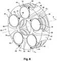
- the method makes it possible to obtain an epicyclic gear train 60, in which the pivots 18 are oriented in the bores 34, by means of the cooperation between the remaining radial protuberances E q of the pivots 18 and the pins 46 arranged around the bores 34 .
- the pivots 18 are interchangeable: they can be mounted indifferently in the two bores 34, provided that the pivots 18 are correctly oriented with the help of their radial outgrowth E q remaining.
- the vector U is positioned on the boundary between two angular sectors
- one of the two sectors is randomly selected as being the sector comprising the vector U .
- the vector - V is positioned on the boundary between two angular sectors
- one of the two sectors is randomly chosen to be the sector comprising the vector - V .
- the pivots 18 and the bores 34 are respectively n and k angular sectors such that n may be greater than or equal to k.
- n and k may be between 3 and 8 inclusive.
Landscapes
- Engineering & Computer Science (AREA)
- General Engineering & Computer Science (AREA)
- Mechanical Engineering (AREA)
- Chemical & Material Sciences (AREA)
- Combustion & Propulsion (AREA)
- Retarders (AREA)
- General Details Of Gearings (AREA)
- Testing Of Devices, Machine Parts, Or Other Structures Thereof (AREA)
Abstract
Description
- La présente invention concerne un procédé d'assemblage pour un train d'engrenages épicycloïdal ou planétaire destiné à équiper une turbomachine, telle que par exemple un turboréacteur ou un turbopropulseur d'avion.
- Une turbomachine peut comprendre un train d'engrenages effectuant la liaison entre son arbre de turbine et un ou plusieurs éléments de sortie, tel par exemple qu'une soufflante. Ce type de train d'engrenages comprend un planétaire interne entraîné par un arbre d'entrée, par exemple un arbre de turbine, un planétaire externe (également appelé couronne), coaxial au planétaire interne, des satellites engrenant à la fois avec le planétaire interne et avec le planétaire externe, et un porte-satellites sur lequel les satellites sont montés rotatifs. Les satellites sont montés de façon mobile en rotation sur des pivots qui sont insérés dans les alésages du porte-satellites.
- Dans une configuration particulière, le train d'engrenages peut effectuer une réduction de la vitesse entre une entrée et une sortie de celui-ci. La variation du rapport de réduction d'un tel train d'engrenages s'obtient par la modification du nombre de dents du planétaire interne, des satellites et du planétaire externe, et par l'architecture du réducteur, c'est-à-dire épicycloïdal ou planétaire. Ces deux types de trains d'engrenages se distinguent l'un de l'autre par le fait que dans le train d'engrenages dit épicycloïdal, la couronne est fixe et le porte-satellites est libre en rotation. A l'inverse, dans le train d'engrenages dit planétaire, le porte-satellites est fixe et le planétaire externe est libre en rotation.
- Il est observé, dans le cas de ces deux types de trains d'engrenages, une disparité au niveau de la puissance transitant par les satellites du porte-satellites. Cette disparité peut résulter en une surcharge des contraintes mécaniques appliquées à certains satellites.
- Selon la norme ANSI/AGMA 6123-B06 établie par l'AGMA (acronyme anglais pour American Gear Manufacturers Association, l'association des fabricants américains d'engrenages), la surcharge de chacun des satellites d'un train épicycloïdal ou planétaire doit être d'environ12%, en conditions réelles de fonctionnement.
- L'une des causes de cette disparité est le défaut de positionnement relatif des satellites, et en particulier les défauts de positionnement tangentiel relatif des satellites les uns par rapport aux autres autour de l'axe du porte-satellites. De plus, le désalignement des dentures des satellites avec les dentures du planétaire interne et du planétaire externe conduisent à une usure prématurée desdites dentures, obligeant à une maintenance régulière augmentant les coûts d'exploitation de la turbomachine.
- Dans la technique actuelle, une solution pour réduire ce phénomène de surcharge consiste à appairer les pivots portant les satellites et les alésages du porte-satellites lors de l'usinage et du montage des pièces. L'appairage consiste à définir des couples, pivot-alésage, de sorte que le pivot et l'alésage d'un couple sont destinés à être assemblés ensemble. Une conséquence d'un tel appairage est que les pivots de deux couples ne sont pas interchangeables.
- L'appairage complexifie la gestion des stocks de pièces lors de l'assemblage ou la maintenance des trains épicycloïdaux. De plus, les opérations d'appairage sont contraignantes puisqu'elles nécessitent des tâches préalables complexes à l'assemblage des éléments constitutifs du porte-satellites, ce qui entraine des coûts de production élevés, et rendent les opérations de maintenance plus complexes.
- L'invention a notamment pour but de réduire les défauts de positionnement des satellites dans le porte-satellites de manière simple, efficace et économique, sans avoir à recourir à l'appairage des pièces ni à modifier les tolérances de fabrication du porte-satellites et des pivots qui pourraient augmenter de manière importante les coûts de fabrication.
- A cet effet, la présente invention concerne un procédé d'assemblage pour un train d'engrenages épicycloïdal ou planétaire à partir d'au moins un pivot et d'un porte-satellites comprenant un ou plusieurs alésages, chacun des alésages étant destiné à recevoir un pivot, le procédé comprenant les étapes suivantes :
- a) mesurer la position d'un axe réel de chacun dudit au moins un pivot et desdits un ou plusieurs alésages du porte-satellites ;
- b) diviser chacun desdits pivots en n secteurs angulaires i 1 ...iq ...in s'étendant autour de l'axe théorique dudit pivot et diviser chacun desdits alésages du porte-satellites en k secteurs angulaires j 1 ...jl ... jk s'étendant autour de l'axe théorique dudit alésage ;
- c) pour chaque pivot définir un vecteur
V orienté de l'axe théorique vers l'axe réel, et identifier le secteur angulaire iq comprenant le vecteur -V ; - d) pour chaque alésage définir un vecteur
U orienté de l'axe théorique vers l'axe réel, et identifier le secteur angulaire jl comprenant le vecteurU ; - e) pour chaque alésage du porte-satellites, monter un pivot tel que pour chaque montage les secteurs angulaires identifiés jl et iq se superposent.
- Les défauts de localisation des alésages sur le porte-satellites ainsi que les défauts de concentricité des pivots contribuent au décalage tangentiel de l'axe réel de rotation par rapport à l'axe théorique.
- Ainsi, bien que les pivots et les alésages présentent individuellement des axes de rotation réels excentrés par rapport à leurs axes de rotation théoriques, l'assemblage selon le procédé de l'invention permet de minimiser l'excentricité des axes de rotation résultant des ensembles pivot-alésage.
- L'orientation du pivot dans le porte-satellites lors de l'étape de montage e) de manière à ce que les vecteurs
U etV ne soient pas disposés dans le même secteur angulaire, permet aux excentricités des axes réels de rotation du pivot et de l'alésage de se compenser en partie. - L'orientation des pièces lors du montage permet alors de corriger le défaut de position tangentiel relatif entre les satellites, et par conséquent, de réduire le phénomène de surcharge des satellites des pivots et des alésages, sans pour autant modifier les tolérances de fabrication des alésages du porte-satellites et des pivots.
- Ce procédé, ne nécessitant pas d'appairage, permet en outre l'interchangeabilité des pièces lors du montage ou des opérations de maintenance. Ainsi, quel que soit le pivot monté dans un des alésages, l'orientation du pivot dans l'alésage, avec le procédé selon l'invention, permet de réduire le défaut résultant de l'ensemble pivot-alésage.
- L'étape e) du procédé peut en outre être réalisée au moyen d'un dispositif de mise en position comprenant des moyens de couplage complémentaires sur les pivots et sur le porte-satellites.
- Le dispositif de mise en position permet d'orienter le pivot et de le fixer dans l'alésage dans une orientation souhaitée lors du montage.
- Les moyens de couplage peuvent comprendre des premiers moyens de couplage par coopération de forme portés par le porte-satellites et des seconds moyens de couplage par coopération de forme portés par les pivots.
- De cette manière, lors du montage d'un pivot dans un alésage, les premiers moyens de couplage portés par le porte-satellites coopèrent avec les seconds moyens de couplage portés par le pivot, afin que ce dernier soit orienté dans l'alésage de sorte à ce que les excentricités du pivot et de l'alésage s'annulent au moins en partie.
- Les premiers moyens de couplage par coopération de forme peuvent comprendre un premier organe en saillie agencé dans le secteur angulaire jl et dans lequel les seconds moyens de couplage par coopération de forme comprennent une ouverture d'introduction dudit premier organe.
- Le premier organe peut être apte à être disposé dans k perçages chacun disposé en périphérie d'un alésage et dans un secteur jl , et dans lequel l'étape d) comprend en outre l'étape suivante :
- insérer le premier organe dans le l-ième perçage positionné dans le secteur angulaire jl .
- Chaque secteur angulaire de chaque pivot peut comprendre un second moyen de couplage formé dans une excroissance radiale Eq du pourtour du pivot, l'étape c) comprend la réalisation d'un détrompage au montage de l'ouverture de l'excroissance radiale Eq dans ledit organe du secteur jl . La réalisation du détrompage consiste à supprimer les excroissances radiales qui ne sont pas comprises dans le secteur angulaire iq identifié.
- Ainsi, une fois les étapes c) et d) du procédé selon l'invention réalisées, chaque alésage comprend un organe porté par le porte-satellites et situé dans le secteur angulaire jl comprenant le vecteur
U et chaque pivot comprend une excroissance radiale Eq comprenant une ouverture, apte à coopérer avec l'organe. L'excroissance radiale Eq est située dans le secteur angulaire iq comprenant le vecteur -V . De cette manière, les secteurs angulaires jl et iq respectivement pour chacun des alésages et pour chacun des pivots sont visuellement identifiés. On peut de plus facilement en déduire les secteurs angulaires où sont positionnés les axes réels des alésages et des pivots. - L'étape d) peut comprendre en outre l'étape suivante :
- orienter le pivot de sorte à insérer le premier organe porté par le porte-satellites dans l'ouverture de l'excroissance radiale Eq restante portée par le pivot.
- Ainsi, en montant le pivot de sorte à insérer l'organe dans l'ouverture de l'excroissance radiale Eq restante du pivot, on s'assure de monter le pivot dans l'alésage en l'orientant de sorte à superposer les secteurs angulaires identifiés jl et iq respectivement de l'alésage et du pivot.
- En superposant les secteurs angulaires jl et iq , les vecteurs
U etV ne sont pas disposés dans le même secteur angulaire, ce qui signifie que le défaut de position des axes réels du pivot et de l'alésage se compensent, au moins en partie. - De plus, la coopération de l'organe et de l'ouverture de l'excroissance radiale Eq permet de réduire les erreurs d'orientation lors du montage du pivot dans l'alésage.
- Ce procédé est une solution industriellement viable, permettant, par ailleurs, d'éviter l'appairage des alésages d'un porte-satellites et des pivots associés.
- Les pivots et alésages sont respectivement divisés en n et k secteurs angulaires tel que n peut être supérieur ou égal à k.
- Ainsi, lorsque n est supérieur à k, la position de l'axe de rotation réel est plus précisément identifiée sur le pivot tout en évitant de découper l'alésage en autant de secteurs angulaires. Comme évoqué précédemment, chacun des secteurs angulaires des alésages comprennent des perçages disposés en périphérie des alésages sur le porte-satellites. De tels perçages en grand nombre sur le porte-satellites peuvent contribuer à son affaiblissement mécanique. Par conséquent, en limitant le nombre de secteurs angulaires k tel que n est supérieur à k, l'affaiblissement mécanique du porte-satellites résultant de la formation des perçages est ainsi réduit et mieux contrôlé.
- Dans un exemple pratique de réalisation de l'invention, n et k peuvent être compris entre 3 et 8, bornes incluses.
- L'invention concerne également un train d'engrenages épicycloïdal ou planétaire susceptible d'être obtenu par le procédé tel que décrit précédemment.
- En outre, l'invention porte sur un train d'engrenages épicycloïdal comprenant un porte-satellites comportant des alésages dans lesquels sont agencés des pivots, les alésages et les pivots comprenant des moyens de couplage aptes à coopérer ensemble afin maintenir le pivot selon une orientation prédéterminée dans l'alésage, lesdits moyens de couplage des alésages et des pivots étant respectivement disposés dans un secteur angulaire comprenant un vecteur
U orienté à partir d'un axe théorique vers un axe réel et dans un secteur angulaire comprenant un vecteur -V , le vecteurV étant orienté à partir d'un axe théorique vers un axe réel. - Par exemple, les moyens de couplage des alésages peuvent comprendre un organe en saillie.
- Également, les moyens de couplage des pivots peuvent comprendre une ouverture, ayant une forme apte à recevoir avec les moyens de couplage des alésages.
- Par ailleurs, l'ouverture est formée dans une excroissance radiale Eq portée par le pivot et est apte à recevoir ledit organe en saillie.
- L'invention sera mieux comprise et d'autres détails, caractéristiques et avantages de l'invention apparaîtront à la lecture de la description suivante faite à titre d'exemple non limitatif en référence aux dessins annexés.
-
- la
figure 1 est un schéma de face d'un train d'engrenages, vu de face, axialement depuis l'amont ; - la
figure 2 est un schéma longitudinal d'une turbomachine ; - la
figure 3 est une vue schématique d'un porte-satellites selon l'invention ; - la
figure 4 est une vue de coupe d'un pivot monté dans un alésage d'un porte-satellites ; - la
figure 5 est une vue schématique d'un pivot selon l'invention avant l'identification du secteur angulaire iq ; - la
figure 6 est une vue schématique d'un pivot pour lequel le secteur iq est identifié ; - les
figures 7a, 7b et 7c illustrent respectivement les étapes du procédé selon l'invention ; - la
figure 8 est une vue schématique d'un train d'engrenages susceptible d'être obtenue par le procédé selon l'invention. - La
figure 1 illustre schématiquement la structure d'un train d'engrenages épicycloïdal ou planétaire 10. Ce type de train d'engrenages 10 comprend classiquement un planétaire interne 12 (également appelé pignon central, soleil ou solaire) et un planétaire externe 14 (également appelé couronne extérieure), les deux planétaires étant coaxiaux. Le planétaire interne 12 peut être mobile en rotation autour de son axe X, le planétaire externe 14 pouvant être fixe, ou couplé en rotation à une hélice comme dans le cas d'un turbopropulseur ou à une roue de soufflante comme dans le cas d'un turboréacteur à double flux. Le train d'engrenages 10 comporte en outre des satellites, ou pignons satellites 16 montés de façon mobile en rotation sur des pivots 18 d'un porte-satellites 20. Chaque satellite 16 engrène simultanément avec le planétaire interne 12 et avec le planétaire externe 14. Le porte-satellites 20 est fixe ou pivotant autour de l'axe X du planétaire interne 12 et du planétaire externe 14. L'entrée peut être formée par le planétaire interne 12, et la sortie formée par le porte-satellites 20. - Dans un autre exemple, le porte-satellites 20 peut être fixe ou couplé en rotation à une hélice d'un turbopropulseur ou à une roue de soufflante d'un turboréacteur à double flux.
- La
figure 2 illustre schématiquement une turbomachine 22 pour aéronef dans laquelle des trains d'engrenages 10 sont utilisés en tant que réducteurs de vitesse pour réduire la vitesse de rotation d'un rotor, tel qu'une soufflante 24, indépendamment de la vitesse de rotation d'au moins une turbine 26 couplée axialement en aval à au moins un compresseur 28 dont la turbomachine est aussi équipée. A partir de l'entrée d'air frontale 30, la soufflante 24, puis le compresseur 28 sont traversés par de l'air. - Le pignon central, ou planétaire interne 12, entoure et est alors solidaire en rotation de l'arbre 32 du compresseur 28 comme illustré par exemple par les
figures 1 et 2 . Le train d'engrenages 10 peut en particulier être monté dans une enceinte annulaire formée radialement à l'intérieur d'un compresseur basse pression 28a agencé en aval de la roue de soufflante 24 et en amont d'un compresseur haute pression 28b comme visible sur lafigure 2 . - Comme cela est visible en considérant la
figure 1 , l'alignement des dentures des satellites avec les dentures des planétaires interne 12 et externe 14 est nécessaire au bon fonctionnement du train d'engrenages 10 et pour limiter les opérations de maintenance. - Un mauvais positionnement des satellites 16 dans les alésages 34 du porte-satellites 20, visibles sur la
figure 3 , implique un désalignement des dentures des satellites 16 avec la denture du planétaire interne 12 et la denture du planétaire externe 14. Il s'ensuit une disparité de la puissance transitant par les satellites 16 conduisant à une usure précoce des dentures. - Il est donc nécessaire de fournir une solution permettant de réduire autant que possible le désalignement des satellites 16 lors du montage de tels trains d'engrenages 10.
- Pour cela, comme illustré sur les
figures 7a, 7b, et 7c , un procédé d'assemblage pour trains d'engrenages 10 est proposé. Le montage peut être effectué à partir d'au moins un pivot 18 et d'un porte-satellites 20 comprenant un ou plusieurs alésages 34. - La
figure 3 illustre un exemple de porte-satellites 20 selon l'invention, à partir duquel est assemblé un train épicycloïdal. Il comprend cinq alésages 34 régulièrement répartis autour de l'axe X et dimensionnés de sorte à ce qu'un pivot 18 puisse y être monté. Un exemple de pivot 18 est visible sur lafigure 5 . Le pivot 18 comprend un axe 36, dont le diamètre est dimensionné de sorte à pouvoir être agencé dans les alésages 34 du porte-satellites 20. L'axe 36 est globalement cylindrique ou tronconique, dont une des extrémités est prolongée par une partie de liaison annulaire 38 s'étendant radialement vers l'extérieur (figure 4 ). - Le montage d'un pivot 18 dans un alésage 34 d'un porte-satellites 20 est par ailleurs visible sur la
figure 4 . L'axe 36 du pivot 18 est agencé à l'intérieur de l'alésage 34 du porte-satellites 20 de sorte que la partie de liaison 38 vienne en appui sur la surface 41 du porte-satellites en périphérie de l'alésage. L'axe du pivot 36 est en libre rotation dans l'alésage 34. - Dans l'exemple illustré par les
figures 7a, 7b, et 7c , le procédé est appliqué à deux alésages 34, d'un même porte-satellites 20 ou deux portes-satellites distincts 20, et à deux pivots 18. - La première étape du procédé consiste à mesurer la position d'un axe de rotation réel 51 de chacun des pivots 18 et la position d'un axe réel 40 de chacun des alésages 34 du ou des portes-satellites. Comme illustré sur la
figure 7a , la mesure, lors de cette première étape, permet connaître la position de l'axe de rotation réel 51 (figure 4 ) par rapport à l'axe de rotation théorique 52 de chacun des pivots 18 et la position de l'axe réel 40 par rapport à l'axe théorique 42 de chacun des alésages 34. - Pour les alésages 34, l'excentricité de l'axe réel 40 par rapport à l'axe théorique 42 résulte en partie de défaut de fabrication impactant notamment la position des alésages 34 dans le porte-satellites. Dans le cas des pivots 18, cette excentricité s'explique par des défauts de fabrication impactant notamment la concentricité des pivots 18.
- La mesure de la position tridimensionnelle des axes réels, respectivement des pivots et des alésages, est réalisée à l'aide d'une machine dédiée. Cette machine permet, par palpation de la circonférence de l'alésage et du pivot, de déterminer, par calcul, la position réelle du centre et donc de l'axe de rotation réel du pivot et de l'axe réel de l'alésage.
- La première étape permet ainsi de connaitre la position relative de l'axe réel 40 par rapport à l'axe théorique 42 des alésages 34 ainsi que la position de l'axe de rotation réel 51 par rapport à l'axe de rotation théorique 52 des pivots 18 à assembler.
- Pour caractériser les positions relatives des axes réels 40, 51 par rapport aux axes théoriques 42, 52 pour chacun des alésages et des pivots, on définit respectivement des vecteurs
U etV dans une troisième et quatrième étape, également illustré par lesfigures 7a, 7b et 7c . - Pour chaque alésage 34, un vecteur
U est défini. Le vecteurU est orienté de l'axe théorique 42 vers l'axe réel 40 et a une norme égale à la distance entre l'axe théorique de rotation 42 et l'axe réel 40 de l'alésage 34. - De manière similaire, pour chaque pivot 18 un vecteur
V est défini. Le vecteurV est orienté de l'axe théorique de rotation 52 vers l'axe réel de rotation et 51 a une norme égale à la distance entre l'axe théorique de rotation 52 et l'axe réel de rotation 51 du pivot 18. - Dans une réalisation pratique, compatible avec l'industrialisation des pièces, le procédé comprend une deuxième étape consistant à diviser régulièrement et indépendamment les pivots 18 en plusieurs secteurs angulaires égaux et les alésages 34 du porte-satellites 20 en plusieurs secteurs angulaires égaux autour de leurs axes théoriques respectifs 42. Ainsi, les pivots 18 et les alésages 34 sont indépendamment divisés régulièrement en n et k secteurs angulaires s'étendant autour de leurs axes théoriques 42 respectifs, n et k pouvant être égaux, comme le cas illustré par les
figures 7a, 7b et 7c où n = k = 4. - Cette division en secteurs angulaires, permet de localiser dans quelle secteur angulaire de la pièce se trouvent les vecteurs
U etV et donc les axes de rotation réels 51 des pivots 18 et les axes réels 40 des alésages 34. On peut ensuite en déduire les sens d'orientation de chacun des alésages et de chacun des pivots. - Une telle division en secteurs angulaires permet en outre d'identifier dans les troisième et quatrième étapes les secteurs angulaires iq et jl , respectivement pour chaque pivot 18 et chaque alésage 34, comprenant respectivement les vecteurs -
V etU . - La cinquième étape du procédé, illustrée par la
figure 7c , consiste à monter un des pivots 18 dans l'alésage 34 et l'orienter angulairement dans celui-ci tel que pour chaque montage 44 les secteurs angulaires identifiés jl et iq se superposent. En d'autres termes, le pivot 18 est monté et orienté dans un des alésages 34 de sorte que les axes de rotation réels 51 du pivot 18 et les axes réels 40 de l'alésage 34 du montage 44, définis les vecteursU etV , se compensent au moins en partie. - Pour cela, le pivot 18 est orienté de sorte que les secteurs angulaires identifiés jl et iq se superposent.
- Comme cela est visible sur la
figure 7c , l'assemblage des pivots 18 peut être réalisé indifféremment dans les deux alésages 34. Toutefois, lors du montage 44, le pivot 18 est monté tel que les vecteursU etV ne soient pas dans le même secteur angulaire, c'est-à-dire afin que les secteurs angulaires identifiés jl et iq se superposent. - Ce procédé ne nécessite pas d'appairage de pièces, de sorte que les pivots 18 peuvent être montés dans tous les alésages 34 à condition que l'orientation du pivot 18 soit respectée.
- En pratique, la cinquième étape du procédé est réalisée au moyen d'un dispositif de mise en position. Le dispositif de mise en position comprend des moyens de couplage complémentaires sur les pivots 18 et sur le porte-satellites 20. Le dispositif de mise en position permet d'orienter le pivot 18 dans l'alésage 34 du porte-satellites 20 et de le fixer dans l'orientation souhaitée lors du montage. En pratique, on comprendra ci-après que le dispositif réalise un détrompage au montage d'un pivot 18 dans un alésage 34, évitant un montage d'une manière inappropriée d'un pivot 18 dans un alésage 34 qui conduirait, au contraire du résultat souhaité, à une augmentation des désalignements des dentures.
- Comme cela est visible sur les
figures 7a, 7b et 7c , les moyens de couplage comprennent des premiers moyens de couplage par coopération de forme portés par le porte-satellites. Ces premiers moyens de couplage comprennent un premier organe 46 apte à être disposé en saillie dans des perçages 48 disposés en périphérie des alésages 34. En particulier, les perçages 48 sont agencés de manière qu'il n'y ait qu'un perçage 48 par secteur angulaire pour chacun des alésages 34 du porte-satellites 20 tel qu'illustré sur lafigure 3 . - Pour chacun des alésages 34, la quatrième étape du procédé comprend en outre une étape consistant à insérer le premier organe 46 dans le perçage 48 positionné dans le secteur angulaire jl , qui comprend par ailleurs le vecteur
U pour chacun des alésages 34. Cette étape permet ainsi, pour chaque alésage 34, d'identifier visuellement le secteur angulaire où se trouve l'axe de réel 40 de l'alésage 34, et d'y disposer un moyen de couplage qui aidera par la suite au montage « orienté » du pivot 18 dans l'alésage 34, c'est-à-dire dans une position angulaire conduisant à une réduction des désalignements des dentures. Sur lafigure 7b , qui illustre en partie cette étape, des pions sont disposés dans les secteurs angulaires j2 et j4 comprenant le vecteurU de ces deux alésages 34. - Comme illustré sur les
figures 7a, 7b et 7c , les moyens de couplage comprennent des seconds moyens de couplage par coopération de forme portés par les pivots 18. Les seconds moyens de couplage par coopération de forme comprennent une ouverture d'introduction 50, de sorte qu'un premier organe 46, par exemple un pion, puisse être agencé à l'intérieur de cette ouverture d'introduction 50. En particulier, comme illustré par lafigure 5 , chaque pivot comprend des seconds moyens de couplage qui sont des excroissances radiales Eq du pourtour 53 du pivot 18. Les excroissances radiales Eq du pourtour 53 des pivots 18 sont disposées sur la partie de liaison 38, en périphérie de celle-ci. En particulier, ces excroissances radiales Eq sont agencées de manière à ce qu'il n'y ait qu'une excroissance Eq par secteur angulaire pour chacun des pivots 18 comme sur lafigure 7a . - Pour chaque pivot 18, la troisième étape du procédé comprend en outre la réalisation d'un détrompage au montage de l'ouverture de l'excroissance radiale Eq dans ledit organe 46 du secteur jl . Ce détrompage consiste à usiner les excroissances radiales Eq qui ne sont pas comprises dans le secteur angulaire iq identifié, comprenant le vecteur -
V . Cette étape permet ainsi pour chaque pivot 18 d'identifier visuellement le secteur angulaire situé en direction opposée au secteur angulaire dans lequel se trouve l'axe de rotation réel 51 du pivot 18, et d'y disposer un moyen de couplage qui facilitera par la suite le montage « orienté » du pivot 18 dans l'alésage 34. Suite à l'usinage, les pivots 18 ne comprennent plus qu'une excroissance radiale comme visible sur lafigure 6 . - Suite aux troisième et quatrième étapes du procédé, comme illustré
figure 7b , les pions 46, les premiers moyens de couplage par coopération de forme portés par les porte-satellites et les excroissances radiales restantes Eq , les seconds moyens de couplage par coopération de forme portés par les pivots, permettent d'identifier, directement ou indirectement, la position et l'orientation des vecteursU etV . - La cinquième étape comprend, dans une réalisation pratique du procédé, une étape consistant à orienter le pivot 18 de sorte à insérer le premier organe 46 en saillie porté par le porte-satellites 20 dans l'ouverture de l'excroissance radiale Eq restante portée par le pivot 18. Comme cela est visible sur la
figure 7c , l'orientation du pivot 18 dans l'alésage 34 de sorte à faire coopérer le pion 46 de l'alésage 34 avec l'excroissance radiale Eq restante du pivot 18 permet d'assurer que l'axe réel de rotation 51 du pivot 18 et l'axe réel 40 de l'alésage 34 ne soient pas disposés dans le même secteur angulaire. - En superposant les secteurs angulaires jl et iq visuellement identifiés sur chacun des alésages 34 et des pivots 18, on s'assure que lors du montage que
U etV sont disposés tel que l'axe réel de rotation 51 du pivot 18 et l'axe réel 40 de l'alésage 34 du montage 44, se compensent au moins en partie. - Comme cela est visible sur la
figure 8 , le procédé permet d'obtenir un train épicycloïdal 60, dans lequel les pivots 18 sont orientés dans les alésages 34, à l'aide de la coopération entre les excroissances radiales Eq restantes des pivots 18 et les pions 46 disposés autour des alésages 34. - Comme illustré sur la
figure 7c , les pivots 18 sont interchangeables : ils peuvent être montés indifféremment dans les deux alésages 34, à condition que les pivots 18 soient correctement orientés à l'aide de leur excroissance radiale Eq restante. - Dans le cas particulier où, pour un alésage 34, le vecteur
U est positionné sur la frontière entre deux secteurs angulaires, on choisit aléatoirement un des deux secteurs comme étant le secteur comprenant le vecteurU . De même pour un pivot 18, lorsque le vecteur -V est positionné sur la frontière entre deux secteurs angulaires, on choisit aléatoirement un des deux secteurs comme étant le secteur comprenant le vecteur -V . Selon une forme de réalisation de l'invention, les pivots 18 et les alésages 34 sont respectivement en n et k secteurs angulaires tel que n peut être supérieur ou égal à k. - Selon une autre forme de réalisation n et k peuvent être compris entre 3 et 8, bornes incluses.
- En particulier, en limitant le nombre de secteurs angulaires des alésages 34, on limite également le nombre de perçage 48 en périphérie des alésages 34 sur les porte-satellites 20. Cela permet de limiter et de contrôler l'affaiblissement du porte-satellites 20 par les perçages 48.
Claims (15)
- Procédé d'assemblage pour un train d'engrenages épicycloïdal ou planétaire (10) à partir d'au moins un pivot (18) et d'un porte-satellites (20) comprenant un ou plusieurs alésages (34), chacun des alésages (34) étant destiné à recevoir un pivot (18), le procédé comprenant les étapes suivantes :a) mesurer la position d'un axe réel (40) de chacun dudit au moins un pivot (18) et desdits un ou plusieurs alésages (34) du porte-satellites (20);b) diviser chacun desdits pivots (18) en n secteurs angulaires i 1...iq ...in s'étendant autour de l'axe théorique (42) dudit pivot et diviser chacun desdits alésages (34) du porte-satellites (20) en k secteurs angulaires j 1 ...jl ...jk s'étendant autour de l'axe théorique (42) dudit alésage (34);c) pour chaque pivot (18) définir un vecteur
V orienté de l'axe théorique (52) vers l'axe réel (51), et identifier le secteur angulaire iq comprenant le vecteur -V ;d) pour chaque alésage (34) définir un vecteurU orienté de l'axe théorique (40) vers l'axe réel (42), et identifier le secteur angulaire jl comprenant le vecteurU ;e) pour chaque alésage (34) du porte-satellites (20), monter un pivot (18) tel que pour chaque montage (44) les secteurs angulaires identifiés jl et iq se superposent. - Procédé selon la revendication 1, dans lequel l'étape e) est réalisée au moyen d'un dispositif de mise en position comprenant des moyens de couplage complémentaires sur les pivots et sur le porte-satellites.
- Procédé selon la revendication 2, dans lequel les moyens de couplage comprennent des premiers moyens de couplage par coopération de forme portés par le porte-satellites (20) et des seconds moyens de couplage par coopération de forme portés par les pivots (18).
- Procédé selon la revendication 3, dans lequel les premiers moyens de couplage par coopération de forme comprennent un premier organe (46) en saillie agencé dans le secteur angulaire jl et dans lequel les seconds moyens de couplage par coopération de forme comprennent une ouverture d'introduction (50) dudit premier organe.
- Procédé selon la revendication 4, dans lequel le premier organe (46) est apte à être disposé dans k perçages (48) chacun disposé en périphérie d'un alésage (34) et dans un secteur jl , et dans lequel l'étape d) comprend en outre l'étape suivante :- insérer le premier organe (46) dans le l-ième perçage (48) positionné dans le secteur angulaire jl .
- Procédé selon la revendication 4 ou 5, dans lequel chaque secteur angulaire de chaque pivot (18) comprenant un second moyen de couplage formé dans une excroissance radiale Eq du pourtour (53) du pivot (18), l'étape c) comprend la réalisation d'un détrompage au montage de l'ouverture (50) de l'excroissance radiale Eq dans ledit organe (46) du secteur jl .
- Procédé selon la revendication 6, dans lequel la réalisation du détrompage consiste à supprimer les excroissances radiales Eq qui ne sont pas comprises dans le secteur angulaire iq .
- Procédé selon la revendication 7, dans lequel l'étape d) comprend en outre l'étape suivante :- orienter le pivot (18) de sorte à insérer le premier organe (46) porté par le porte-satellites (20) dans l'ouverture (50) de l'excroissance radiale Eq restante portée par le pivot (18).
- Procédé selon l'une des revendications 1 à 8, dans lequel n est supérieur ou égal à k.
- Procédé selon l'une des revendications 1 à 9, dans lequel n et k sont compris entre 3 et 8, bornes incluses.
- Train d'engrenages épicycloïdal (60) susceptible d'être obtenu par le procédé selon l'une des revendications 1 à 10.
- Train d'engrenages épicycloïdal (60) comprenant un porte-satellites (20) comportant des alésages (34) dans lesquels sont agencés des pivots (18), les alésages (34) et les pivots (18) comprenant des moyens de couplage aptes à coopérer ensemble afin maintenir le pivot (18) selon une orientation prédéterminée dans l'alésage (34), lesdits moyens de couplage des alésages (34) et des pivots (18) étant respectivement disposés dans un secteur angulaire comprenant un vecteur
U orienté à partir d'un axe théorique (52) vers un axe réel (54) et dans un secteur angulaire comprenant un vecteur -V , le vecteurV étant orienté à partir d'un axe théorique (48) vers un axe réel (46). - Train d'engrenages selon la revendication 12, caractérisé en ce que les moyens de couplage des alésages (34) comprennent un organe (46) en saillie.
- Train d'engrenages selon la revendication 13, caractérisé en ce que les moyens de couplage des pivots (18) comprennent une ouverture (50), ayant une forme apte à recevoir avec les moyens de couplage des alésages (34).
- Train d'engrenages épicycloïdal (60) selon la revendication 14, caractérisé en ce que l'ouverture (50) est formée dans une excroissance radiale Eq portée par le pivot (18) et est apte à recevoir ledit organe (46) en saillie.
Applications Claiming Priority (1)
| Application Number | Priority Date | Filing Date | Title |
|---|---|---|---|
| FR1853650A FR3080552B1 (fr) | 2018-04-26 | 2018-04-26 | Procede d'assemblage pour un train d'engrenages |
Publications (2)
| Publication Number | Publication Date |
|---|---|
| EP3561267A1 true EP3561267A1 (fr) | 2019-10-30 |
| EP3561267B1 EP3561267B1 (fr) | 2022-02-16 |
Family
ID=63294344
Family Applications (1)
| Application Number | Title | Priority Date | Filing Date |
|---|---|---|---|
| EP19171453.4A Active EP3561267B1 (fr) | 2018-04-26 | 2019-04-26 | Procede d'assemblage pour un train d'engrenages |
Country Status (4)
| Country | Link |
|---|---|
| US (1) | US11118671B2 (fr) |
| EP (1) | EP3561267B1 (fr) |
| CN (1) | CN110410463B (fr) |
| FR (1) | FR3080552B1 (fr) |
Families Citing this family (4)
| Publication number | Priority date | Publication date | Assignee | Title |
|---|---|---|---|---|
| DE102017201116A1 (de) * | 2017-01-24 | 2018-07-26 | Bayerische Motoren Werke Aktiengesellschaft | Anordnung einer Achse oder einer Welle an einem Bauelement, insbesondere für ein Fahrzeug, sowie Fahrzeug mit einer solchen Anordnung |
| FR3115340B1 (fr) * | 2020-10-16 | 2022-09-16 | Safran Aircraft Engines | Système propulsif aéronautique ayant un rendement propulsif amélioré |
| US12104541B1 (en) | 2023-05-09 | 2024-10-01 | Pratt & Whitney Canada Corp. | Method and system for assembling a reduction gearbox |
| FR3163978A1 (fr) | 2024-06-28 | 2026-01-02 | Safran Transmission Systems | Reducteur mecanique pour une turbomachine d’aeronef |
Citations (3)
| Publication number | Priority date | Publication date | Assignee | Title |
|---|---|---|---|---|
| FR2914719A1 (fr) * | 2007-04-05 | 2008-10-10 | Peugeot Citroen Automobiles Sa | Train d'engrenages epicycloidal et boite de vitesses equipe d'un tel train |
| US20100056321A1 (en) * | 2008-08-27 | 2010-03-04 | Tony Snyder | Gearing arrangement |
| US20130251511A1 (en) * | 2012-03-26 | 2013-09-26 | James B. Coffin | Torque frame bushing arrangement for gas turbine engine fan drive gear system |
Family Cites Families (8)
| Publication number | Priority date | Publication date | Assignee | Title |
|---|---|---|---|---|
| SU887833A1 (ru) * | 1980-04-18 | 1981-12-07 | Государственный Научно-Исследовательский Институт Машиноведения Им. Акад. А.А. Благонравова | Способ компенсации погрешностей зацеплени зубчатых колес |
| JPS6372947A (ja) * | 1986-09-12 | 1988-04-02 | Takashi Takahashi | 制御用変速装置 |
| FR2753249B1 (fr) * | 1996-09-10 | 1998-11-06 | Staubli Sa Ets | Procede d'assemblage d'un reducteur epicycloidal et reducteur epicycloidal |
| GB2413836B (en) * | 2005-07-08 | 2006-04-12 | Orbital 2 Ltd | A gear mounting |
| CA2682454C (fr) * | 2009-04-14 | 2013-11-26 | Kawasaki Jukogyo Kabushiki Kaisha | Appareil a demultiplicateurs planetaires |
| RU2444658C1 (ru) * | 2010-11-09 | 2012-03-10 | Открытое Акционерное Общество "Московский Вертолетный Завод Им. М.Л. Миля" | Планетарная передача |
| WO2012074096A1 (fr) * | 2010-12-02 | 2012-06-07 | 株式会社ジェイテクト | Réducteur du type oscillant excentrique |
| US10781911B2 (en) * | 2018-09-13 | 2020-09-22 | Cnh Industrial America Llc | Planetary gear assembly |
-
2018
- 2018-04-26 FR FR1853650A patent/FR3080552B1/fr active Active
-
2019
- 2019-04-26 EP EP19171453.4A patent/EP3561267B1/fr active Active
- 2019-04-26 US US16/395,681 patent/US11118671B2/en active Active
- 2019-04-26 CN CN201910345685.6A patent/CN110410463B/zh active Active
Patent Citations (3)
| Publication number | Priority date | Publication date | Assignee | Title |
|---|---|---|---|---|
| FR2914719A1 (fr) * | 2007-04-05 | 2008-10-10 | Peugeot Citroen Automobiles Sa | Train d'engrenages epicycloidal et boite de vitesses equipe d'un tel train |
| US20100056321A1 (en) * | 2008-08-27 | 2010-03-04 | Tony Snyder | Gearing arrangement |
| US20130251511A1 (en) * | 2012-03-26 | 2013-09-26 | James B. Coffin | Torque frame bushing arrangement for gas turbine engine fan drive gear system |
Also Published As
| Publication number | Publication date |
|---|---|
| CN110410463A (zh) | 2019-11-05 |
| FR3080552B1 (fr) | 2022-01-21 |
| US11118671B2 (en) | 2021-09-14 |
| CN110410463B (zh) | 2025-01-28 |
| US20190331212A1 (en) | 2019-10-31 |
| EP3561267B1 (fr) | 2022-02-16 |
| FR3080552A1 (fr) | 2019-11-01 |
Similar Documents
| Publication | Publication Date | Title |
|---|---|---|
| EP3464955B1 (fr) | Procédé d'assemblage d'un porte-satellites | |
| EP3561267B1 (fr) | Procede d'assemblage pour un train d'engrenages | |
| EP3649373B1 (fr) | Couronne de reducteur epicycloidal ou planetaire pour une turbomachine | |
| EP3649378B1 (fr) | Couronne de reducteur epicycloïdal ou planetaire pour une turbomachine | |
| EP1816374B1 (fr) | Procédé de fabrication d'un réducteur, réducteur et robot incorporant un tel réducteur | |
| EP3561266B1 (fr) | Procede d'assemblage pour un train d'engrenages epicycloïdal ou planetaire | |
| EP3350420A1 (fr) | Interface et dispositif de support pour carter moteur | |
| FR3108670A1 (fr) | Module de soufflante pour un banc d’essai de turbomachine d’aeronef | |
| FR3046951A1 (fr) | Procede de fabrication d'une piece d'une turbomachine et piece ainsi realisee | |
| EP3362706B1 (fr) | Couronne dentée pour réducteur épicycloïdal | |
| EP3803159B1 (fr) | Procede d'assemblage d'un reducteur et installation de mise en oeuvre du procede | |
| FR3158336A1 (fr) | Ensemble de réglage angulaire à roue et vis sans fin pour aube à orientation réglable et procédé de réglage associé | |
| FR3071868B1 (fr) | Bras pour carter de turbomachine comprenant un corps et une piece amovible | |
| EP3449099B1 (fr) | Bras pour carter de turbomachine comprenant une pièce additionnelle amovible | |
| FR3047776B1 (fr) | Turbomachine et son procede de montage | |
| FR3158363A1 (fr) | Ensemble de réglage angulaire à roues dentées parallèles pour aube à orientation réglable et procédé de réglage associé | |
| FR3158362A1 (fr) | Ensemble de réglage angulaire à engrenage conique pour aube à orientation réglable et procédé de réglage associé | |
| EP4273391B1 (fr) | Procédé de pré-assemblage pour une turbomachine d'aéronef | |
| EP4594600A1 (fr) | Modularite d'une turbomachine d'aeronef par un dispositif de blocage axial et en rotation, procede de montage correspondant | |
| FR3153844A1 (fr) | Dispositif de centrage amélioré pour l’assemblage de disques aubagés de turbine | |
| WO2025088266A1 (fr) | Transmission de puissance dans une turbomachine d'aeronef | |
| FR3108360A1 (fr) | Procede et dispositif d’equilibrage d’une piece tournante pour une turbomachine d’aeronef |
Legal Events
| Date | Code | Title | Description |
|---|---|---|---|
| PUAI | Public reference made under article 153(3) epc to a published international application that has entered the european phase |
Free format text: ORIGINAL CODE: 0009012 |
|
| STAA | Information on the status of an ep patent application or granted ep patent |
Free format text: STATUS: THE APPLICATION HAS BEEN PUBLISHED |
|
| AK | Designated contracting states |
Kind code of ref document: A1 Designated state(s): AL AT BE BG CH CY CZ DE DK EE ES FI FR GB GR HR HU IE IS IT LI LT LU LV MC MK MT NL NO PL PT RO RS SE SI SK SM TR |
|
| AX | Request for extension of the european patent |
Extension state: BA ME |
|
| STAA | Information on the status of an ep patent application or granted ep patent |
Free format text: STATUS: REQUEST FOR EXAMINATION WAS MADE |
|
| 17P | Request for examination filed |
Effective date: 20200429 |
|
| RBV | Designated contracting states (corrected) |
Designated state(s): AL AT BE BG CH CY CZ DE DK EE ES FI FR GB GR HR HU IE IS IT LI LT LU LV MC MK MT NL NO PL PT RO RS SE SI SK SM TR |
|
| RIC1 | Information provided on ipc code assigned before grant |
Ipc: F02C 7/36 20060101AFI20200818BHEP Ipc: F16H 57/08 20060101ALI20200818BHEP |
|
| GRAP | Despatch of communication of intention to grant a patent |
Free format text: ORIGINAL CODE: EPIDOSNIGR1 |
|
| STAA | Information on the status of an ep patent application or granted ep patent |
Free format text: STATUS: GRANT OF PATENT IS INTENDED |
|
| INTG | Intention to grant announced |
Effective date: 20201001 |
|
| GRAJ | Information related to disapproval of communication of intention to grant by the applicant or resumption of examination proceedings by the epo deleted |
Free format text: ORIGINAL CODE: EPIDOSDIGR1 |
|
| STAA | Information on the status of an ep patent application or granted ep patent |
Free format text: STATUS: REQUEST FOR EXAMINATION WAS MADE |
|
| INTC | Intention to grant announced (deleted) | ||
| GRAS | Grant fee paid |
Free format text: ORIGINAL CODE: EPIDOSNIGR3 |
|
| STAA | Information on the status of an ep patent application or granted ep patent |
Free format text: STATUS: GRANT OF PATENT IS INTENDED |
|
| GRAP | Despatch of communication of intention to grant a patent |
Free format text: ORIGINAL CODE: EPIDOSNIGR1 |
|
| INTG | Intention to grant announced |
Effective date: 20210326 |
|
| RIN1 | Information on inventor provided before grant (corrected) |
Inventor name: SIMON, ADRIEN, LOUIS Inventor name: NIEPCERON, CLEMENT, PAUL, RENE |
|
| GRAJ | Information related to disapproval of communication of intention to grant by the applicant or resumption of examination proceedings by the epo deleted |
Free format text: ORIGINAL CODE: EPIDOSDIGR1 |
|
| GRAL | Information related to payment of fee for publishing/printing deleted |
Free format text: ORIGINAL CODE: EPIDOSDIGR3 |
|
| STAA | Information on the status of an ep patent application or granted ep patent |
Free format text: STATUS: REQUEST FOR EXAMINATION WAS MADE |
|
| INTC | Intention to grant announced (deleted) | ||
| GRAP | Despatch of communication of intention to grant a patent |
Free format text: ORIGINAL CODE: EPIDOSNIGR1 |
|
| STAA | Information on the status of an ep patent application or granted ep patent |
Free format text: STATUS: GRANT OF PATENT IS INTENDED |
|
| INTG | Intention to grant announced |
Effective date: 20210908 |
|
| GRAA | (expected) grant |
Free format text: ORIGINAL CODE: 0009210 |
|
| STAA | Information on the status of an ep patent application or granted ep patent |
Free format text: STATUS: THE PATENT HAS BEEN GRANTED |
|
| AK | Designated contracting states |
Kind code of ref document: B1 Designated state(s): AL AT BE BG CH CY CZ DE DK EE ES FI FR GB GR HR HU IE IS IT LI LT LU LV MC MK MT NL NO PL PT RO RS SE SI SK SM TR |
|
| REG | Reference to a national code |
Ref country code: GB Ref legal event code: FG4D Free format text: NOT ENGLISH |
|
| REG | Reference to a national code |
Ref country code: CH Ref legal event code: EP |
|
| REG | Reference to a national code |
Ref country code: DE Ref legal event code: R096 Ref document number: 602019011588 Country of ref document: DE |
|
| REG | Reference to a national code |
Ref country code: AT Ref legal event code: REF Ref document number: 1469020 Country of ref document: AT Kind code of ref document: T Effective date: 20220315 |
|
| REG | Reference to a national code |
Ref country code: IE Ref legal event code: FG4D Free format text: LANGUAGE OF EP DOCUMENT: FRENCH |
|
| REG | Reference to a national code |
Ref country code: LT Ref legal event code: MG9D |
|
| REG | Reference to a national code |
Ref country code: NL Ref legal event code: MP Effective date: 20220216 |
|
| REG | Reference to a national code |
Ref country code: AT Ref legal event code: MK05 Ref document number: 1469020 Country of ref document: AT Kind code of ref document: T Effective date: 20220216 |
|
| PG25 | Lapsed in a contracting state [announced via postgrant information from national office to epo] |
Ref country code: SE Free format text: LAPSE BECAUSE OF FAILURE TO SUBMIT A TRANSLATION OF THE DESCRIPTION OR TO PAY THE FEE WITHIN THE PRESCRIBED TIME-LIMIT Effective date: 20220216 Ref country code: RS Free format text: LAPSE BECAUSE OF FAILURE TO SUBMIT A TRANSLATION OF THE DESCRIPTION OR TO PAY THE FEE WITHIN THE PRESCRIBED TIME-LIMIT Effective date: 20220216 Ref country code: PT Free format text: LAPSE BECAUSE OF FAILURE TO SUBMIT A TRANSLATION OF THE DESCRIPTION OR TO PAY THE FEE WITHIN THE PRESCRIBED TIME-LIMIT Effective date: 20220616 Ref country code: NO Free format text: LAPSE BECAUSE OF FAILURE TO SUBMIT A TRANSLATION OF THE DESCRIPTION OR TO PAY THE FEE WITHIN THE PRESCRIBED TIME-LIMIT Effective date: 20220516 Ref country code: NL Free format text: LAPSE BECAUSE OF FAILURE TO SUBMIT A TRANSLATION OF THE DESCRIPTION OR TO PAY THE FEE WITHIN THE PRESCRIBED TIME-LIMIT Effective date: 20220216 Ref country code: LT Free format text: LAPSE BECAUSE OF FAILURE TO SUBMIT A TRANSLATION OF THE DESCRIPTION OR TO PAY THE FEE WITHIN THE PRESCRIBED TIME-LIMIT Effective date: 20220216 Ref country code: HR Free format text: LAPSE BECAUSE OF FAILURE TO SUBMIT A TRANSLATION OF THE DESCRIPTION OR TO PAY THE FEE WITHIN THE PRESCRIBED TIME-LIMIT Effective date: 20220216 Ref country code: ES Free format text: LAPSE BECAUSE OF FAILURE TO SUBMIT A TRANSLATION OF THE DESCRIPTION OR TO PAY THE FEE WITHIN THE PRESCRIBED TIME-LIMIT Effective date: 20220216 Ref country code: BG Free format text: LAPSE BECAUSE OF FAILURE TO SUBMIT A TRANSLATION OF THE DESCRIPTION OR TO PAY THE FEE WITHIN THE PRESCRIBED TIME-LIMIT Effective date: 20220516 |
|
| PG25 | Lapsed in a contracting state [announced via postgrant information from national office to epo] |
Ref country code: PL Free format text: LAPSE BECAUSE OF FAILURE TO SUBMIT A TRANSLATION OF THE DESCRIPTION OR TO PAY THE FEE WITHIN THE PRESCRIBED TIME-LIMIT Effective date: 20220216 Ref country code: LV Free format text: LAPSE BECAUSE OF FAILURE TO SUBMIT A TRANSLATION OF THE DESCRIPTION OR TO PAY THE FEE WITHIN THE PRESCRIBED TIME-LIMIT Effective date: 20220216 Ref country code: GR Free format text: LAPSE BECAUSE OF FAILURE TO SUBMIT A TRANSLATION OF THE DESCRIPTION OR TO PAY THE FEE WITHIN THE PRESCRIBED TIME-LIMIT Effective date: 20220517 Ref country code: FI Free format text: LAPSE BECAUSE OF FAILURE TO SUBMIT A TRANSLATION OF THE DESCRIPTION OR TO PAY THE FEE WITHIN THE PRESCRIBED TIME-LIMIT Effective date: 20220216 Ref country code: AT Free format text: LAPSE BECAUSE OF FAILURE TO SUBMIT A TRANSLATION OF THE DESCRIPTION OR TO PAY THE FEE WITHIN THE PRESCRIBED TIME-LIMIT Effective date: 20220216 |
|
| PG25 | Lapsed in a contracting state [announced via postgrant information from national office to epo] |
Ref country code: IS Free format text: LAPSE BECAUSE OF FAILURE TO SUBMIT A TRANSLATION OF THE DESCRIPTION OR TO PAY THE FEE WITHIN THE PRESCRIBED TIME-LIMIT Effective date: 20220617 |
|
| PG25 | Lapsed in a contracting state [announced via postgrant information from national office to epo] |
Ref country code: SM Free format text: LAPSE BECAUSE OF FAILURE TO SUBMIT A TRANSLATION OF THE DESCRIPTION OR TO PAY THE FEE WITHIN THE PRESCRIBED TIME-LIMIT Effective date: 20220216 Ref country code: SK Free format text: LAPSE BECAUSE OF FAILURE TO SUBMIT A TRANSLATION OF THE DESCRIPTION OR TO PAY THE FEE WITHIN THE PRESCRIBED TIME-LIMIT Effective date: 20220216 Ref country code: RO Free format text: LAPSE BECAUSE OF FAILURE TO SUBMIT A TRANSLATION OF THE DESCRIPTION OR TO PAY THE FEE WITHIN THE PRESCRIBED TIME-LIMIT Effective date: 20220216 Ref country code: EE Free format text: LAPSE BECAUSE OF FAILURE TO SUBMIT A TRANSLATION OF THE DESCRIPTION OR TO PAY THE FEE WITHIN THE PRESCRIBED TIME-LIMIT Effective date: 20220216 Ref country code: DK Free format text: LAPSE BECAUSE OF FAILURE TO SUBMIT A TRANSLATION OF THE DESCRIPTION OR TO PAY THE FEE WITHIN THE PRESCRIBED TIME-LIMIT Effective date: 20220216 Ref country code: CZ Free format text: LAPSE BECAUSE OF FAILURE TO SUBMIT A TRANSLATION OF THE DESCRIPTION OR TO PAY THE FEE WITHIN THE PRESCRIBED TIME-LIMIT Effective date: 20220216 |
|
| REG | Reference to a national code |
Ref country code: DE Ref legal event code: R097 Ref document number: 602019011588 Country of ref document: DE |
|
| PG25 | Lapsed in a contracting state [announced via postgrant information from national office to epo] |
Ref country code: AL Free format text: LAPSE BECAUSE OF FAILURE TO SUBMIT A TRANSLATION OF THE DESCRIPTION OR TO PAY THE FEE WITHIN THE PRESCRIBED TIME-LIMIT Effective date: 20220216 |
|
| REG | Reference to a national code |
Ref country code: CH Ref legal event code: PL |
|
| PLBE | No opposition filed within time limit |
Free format text: ORIGINAL CODE: 0009261 |
|
| STAA | Information on the status of an ep patent application or granted ep patent |
Free format text: STATUS: NO OPPOSITION FILED WITHIN TIME LIMIT |
|
| REG | Reference to a national code |
Ref country code: BE Ref legal event code: MM Effective date: 20220430 |
|
| 26N | No opposition filed |
Effective date: 20221117 |
|
| PG25 | Lapsed in a contracting state [announced via postgrant information from national office to epo] |
Ref country code: MC Free format text: LAPSE BECAUSE OF FAILURE TO SUBMIT A TRANSLATION OF THE DESCRIPTION OR TO PAY THE FEE WITHIN THE PRESCRIBED TIME-LIMIT Effective date: 20220216 Ref country code: LU Free format text: LAPSE BECAUSE OF NON-PAYMENT OF DUE FEES Effective date: 20220426 Ref country code: LI Free format text: LAPSE BECAUSE OF NON-PAYMENT OF DUE FEES Effective date: 20220430 Ref country code: CH Free format text: LAPSE BECAUSE OF NON-PAYMENT OF DUE FEES Effective date: 20220430 |
|
| PG25 | Lapsed in a contracting state [announced via postgrant information from national office to epo] |
Ref country code: SI Free format text: LAPSE BECAUSE OF FAILURE TO SUBMIT A TRANSLATION OF THE DESCRIPTION OR TO PAY THE FEE WITHIN THE PRESCRIBED TIME-LIMIT Effective date: 20220216 Ref country code: BE Free format text: LAPSE BECAUSE OF NON-PAYMENT OF DUE FEES Effective date: 20220430 |
|
| PG25 | Lapsed in a contracting state [announced via postgrant information from national office to epo] |
Ref country code: IE Free format text: LAPSE BECAUSE OF NON-PAYMENT OF DUE FEES Effective date: 20220426 |
|
| PG25 | Lapsed in a contracting state [announced via postgrant information from national office to epo] |
Ref country code: IT Free format text: LAPSE BECAUSE OF FAILURE TO SUBMIT A TRANSLATION OF THE DESCRIPTION OR TO PAY THE FEE WITHIN THE PRESCRIBED TIME-LIMIT Effective date: 20220216 |
|
| PG25 | Lapsed in a contracting state [announced via postgrant information from national office to epo] |
Ref country code: HU Free format text: LAPSE BECAUSE OF FAILURE TO SUBMIT A TRANSLATION OF THE DESCRIPTION OR TO PAY THE FEE WITHIN THE PRESCRIBED TIME-LIMIT; INVALID AB INITIO Effective date: 20190426 |
|
| PG25 | Lapsed in a contracting state [announced via postgrant information from national office to epo] |
Ref country code: MK Free format text: LAPSE BECAUSE OF FAILURE TO SUBMIT A TRANSLATION OF THE DESCRIPTION OR TO PAY THE FEE WITHIN THE PRESCRIBED TIME-LIMIT Effective date: 20220216 Ref country code: CY Free format text: LAPSE BECAUSE OF FAILURE TO SUBMIT A TRANSLATION OF THE DESCRIPTION OR TO PAY THE FEE WITHIN THE PRESCRIBED TIME-LIMIT Effective date: 20220216 |
|
| PG25 | Lapsed in a contracting state [announced via postgrant information from national office to epo] |
Ref country code: MT Free format text: LAPSE BECAUSE OF FAILURE TO SUBMIT A TRANSLATION OF THE DESCRIPTION OR TO PAY THE FEE WITHIN THE PRESCRIBED TIME-LIMIT Effective date: 20220216 |
|
| PGFP | Annual fee paid to national office [announced via postgrant information from national office to epo] |
Ref country code: DE Payment date: 20250417 Year of fee payment: 7 |
|
| PGFP | Annual fee paid to national office [announced via postgrant information from national office to epo] |
Ref country code: FR Payment date: 20250422 Year of fee payment: 7 |
|
| PG25 | Lapsed in a contracting state [announced via postgrant information from national office to epo] |
Ref country code: TR Free format text: LAPSE BECAUSE OF FAILURE TO SUBMIT A TRANSLATION OF THE DESCRIPTION OR TO PAY THE FEE WITHIN THE PRESCRIBED TIME-LIMIT Effective date: 20220216 |
|
| PGFP | Annual fee paid to national office [announced via postgrant information from national office to epo] |
Ref country code: GB Payment date: 20260327 Year of fee payment: 8 |