EP3561259A1 - System and method for preventing the compressor surge in an internal combustion engine provided with two compressors - Google Patents
System and method for preventing the compressor surge in an internal combustion engine provided with two compressors Download PDFInfo
- Publication number
- EP3561259A1 EP3561259A1 EP19156798.1A EP19156798A EP3561259A1 EP 3561259 A1 EP3561259 A1 EP 3561259A1 EP 19156798 A EP19156798 A EP 19156798A EP 3561259 A1 EP3561259 A1 EP 3561259A1
- Authority
- EP
- European Patent Office
- Prior art keywords
- booster
- variable valve
- engine
- engine system
- compressor
- Prior art date
- Legal status (The legal status is an assumption and is not a legal conclusion. Google has not performed a legal analysis and makes no representation as to the accuracy of the status listed.)
- Withdrawn
Links
- 238000000034 method Methods 0.000 title claims description 10
- 238000002485 combustion reaction Methods 0.000 title description 19
- 238000004891 communication Methods 0.000 claims abstract description 11
- 238000011144 upstream manufacturing Methods 0.000 claims abstract description 9
- 150000001875 compounds Chemical class 0.000 claims abstract description 8
- 230000006835 compression Effects 0.000 claims description 14
- 238000007906 compression Methods 0.000 claims description 14
- 230000008569 process Effects 0.000 claims description 5
- 239000007789 gas Substances 0.000 description 3
- 230000001419 dependent effect Effects 0.000 description 2
- 230000000977 initiatory effect Effects 0.000 description 2
- 230000001105 regulatory effect Effects 0.000 description 2
- 230000001133 acceleration Effects 0.000 description 1
- 230000005540 biological transmission Effects 0.000 description 1
- 230000003247 decreasing effect Effects 0.000 description 1
- 230000000694 effects Effects 0.000 description 1
- 238000004146 energy storage Methods 0.000 description 1
- 239000000446 fuel Substances 0.000 description 1
- 238000012986 modification Methods 0.000 description 1
- 230000004048 modification Effects 0.000 description 1
- 230000007704 transition Effects 0.000 description 1
- XLYOFNOQVPJJNP-UHFFFAOYSA-N water Substances O XLYOFNOQVPJJNP-UHFFFAOYSA-N 0.000 description 1
Images

Classifications
-
- F—MECHANICAL ENGINEERING; LIGHTING; HEATING; WEAPONS; BLASTING
- F02—COMBUSTION ENGINES; HOT-GAS OR COMBUSTION-PRODUCT ENGINE PLANTS
- F02B—INTERNAL-COMBUSTION PISTON ENGINES; COMBUSTION ENGINES IN GENERAL
- F02B37/00—Engines characterised by provision of pumps driven at least for part of the time by exhaust
- F02B37/013—Engines characterised by provision of pumps driven at least for part of the time by exhaust with exhaust-driven pumps arranged in series
-
- F—MECHANICAL ENGINEERING; LIGHTING; HEATING; WEAPONS; BLASTING
- F02—COMBUSTION ENGINES; HOT-GAS OR COMBUSTION-PRODUCT ENGINE PLANTS
- F02B—INTERNAL-COMBUSTION PISTON ENGINES; COMBUSTION ENGINES IN GENERAL
- F02B33/00—Engines characterised by provision of pumps for charging or scavenging
- F02B33/44—Passages conducting the charge from the pump to the engine inlet, e.g. reservoirs
- F02B33/446—Passages conducting the charge from the pump to the engine inlet, e.g. reservoirs having valves for admission of atmospheric air to engine, e.g. at starting
-
- F—MECHANICAL ENGINEERING; LIGHTING; HEATING; WEAPONS; BLASTING
- F02—COMBUSTION ENGINES; HOT-GAS OR COMBUSTION-PRODUCT ENGINE PLANTS
- F02B—INTERNAL-COMBUSTION PISTON ENGINES; COMBUSTION ENGINES IN GENERAL
- F02B37/00—Engines characterised by provision of pumps driven at least for part of the time by exhaust
- F02B37/04—Engines with exhaust drive and other drive of pumps, e.g. with exhaust-driven pump and mechanically-driven second pump
-
- F—MECHANICAL ENGINEERING; LIGHTING; HEATING; WEAPONS; BLASTING
- F02—COMBUSTION ENGINES; HOT-GAS OR COMBUSTION-PRODUCT ENGINE PLANTS
- F02B—INTERNAL-COMBUSTION PISTON ENGINES; COMBUSTION ENGINES IN GENERAL
- F02B37/00—Engines characterised by provision of pumps driven at least for part of the time by exhaust
- F02B37/12—Control of the pumps
- F02B37/16—Control of the pumps by bypassing charging air
-
- F—MECHANICAL ENGINEERING; LIGHTING; HEATING; WEAPONS; BLASTING
- F02—COMBUSTION ENGINES; HOT-GAS OR COMBUSTION-PRODUCT ENGINE PLANTS
- F02B—INTERNAL-COMBUSTION PISTON ENGINES; COMBUSTION ENGINES IN GENERAL
- F02B37/00—Engines characterised by provision of pumps driven at least for part of the time by exhaust
- F02B37/12—Control of the pumps
- F02B37/16—Control of the pumps by bypassing charging air
- F02B37/162—Control of the pumps by bypassing charging air by bypassing, e.g. partially, intake air from pump inlet to pump outlet
-
- F—MECHANICAL ENGINEERING; LIGHTING; HEATING; WEAPONS; BLASTING
- F02—COMBUSTION ENGINES; HOT-GAS OR COMBUSTION-PRODUCT ENGINE PLANTS
- F02B—INTERNAL-COMBUSTION PISTON ENGINES; COMBUSTION ENGINES IN GENERAL
- F02B37/00—Engines characterised by provision of pumps driven at least for part of the time by exhaust
- F02B37/12—Control of the pumps
- F02B37/22—Control of the pumps by varying cross-section of exhaust passages or air passages, e.g. by throttling turbine inlets or outlets or by varying effective number of guide conduits
- F02B37/225—Control of the pumps by varying cross-section of exhaust passages or air passages, e.g. by throttling turbine inlets or outlets or by varying effective number of guide conduits air passages
-
- F—MECHANICAL ENGINEERING; LIGHTING; HEATING; WEAPONS; BLASTING
- F02—COMBUSTION ENGINES; HOT-GAS OR COMBUSTION-PRODUCT ENGINE PLANTS
- F02B—INTERNAL-COMBUSTION PISTON ENGINES; COMBUSTION ENGINES IN GENERAL
- F02B39/00—Component parts, details, or accessories relating to, driven charging or scavenging pumps, not provided for in groups F02B33/00 - F02B37/00
- F02B39/02—Drives of pumps; Varying pump drive gear ratio
- F02B39/08—Non-mechanical drives, e.g. fluid drives having variable gear ratio
- F02B39/10—Non-mechanical drives, e.g. fluid drives having variable gear ratio electric
-
- F—MECHANICAL ENGINEERING; LIGHTING; HEATING; WEAPONS; BLASTING
- F02—COMBUSTION ENGINES; HOT-GAS OR COMBUSTION-PRODUCT ENGINE PLANTS
- F02B—INTERNAL-COMBUSTION PISTON ENGINES; COMBUSTION ENGINES IN GENERAL
- F02B51/00—Other methods of operating engines involving pretreating of, or adding substances to, combustion air, fuel, or fuel-air mixture of the engines
- F02B51/04—Other methods of operating engines involving pretreating of, or adding substances to, combustion air, fuel, or fuel-air mixture of the engines involving electricity or magnetism
-
- F—MECHANICAL ENGINEERING; LIGHTING; HEATING; WEAPONS; BLASTING
- F02—COMBUSTION ENGINES; HOT-GAS OR COMBUSTION-PRODUCT ENGINE PLANTS
- F02D—CONTROLLING COMBUSTION ENGINES
- F02D41/00—Electrical control of supply of combustible mixture or its constituents
- F02D41/0002—Controlling intake air
- F02D41/0007—Controlling intake air for control of turbo-charged or super-charged engines
-
- F—MECHANICAL ENGINEERING; LIGHTING; HEATING; WEAPONS; BLASTING
- F02—COMBUSTION ENGINES; HOT-GAS OR COMBUSTION-PRODUCT ENGINE PLANTS
- F02M—SUPPLYING COMBUSTION ENGINES IN GENERAL WITH COMBUSTIBLE MIXTURES OR CONSTITUENTS THEREOF
- F02M37/00—Apparatus or systems for feeding liquid fuel from storage containers to carburettors or fuel-injection apparatus; Arrangements for purifying liquid fuel specially adapted for, or arranged on, internal-combustion engines
- F02M37/04—Feeding by means of driven pumps
- F02M37/08—Feeding by means of driven pumps electrically driven
- F02M37/10—Feeding by means of driven pumps electrically driven submerged in fuel, e.g. in reservoir
-
- F—MECHANICAL ENGINEERING; LIGHTING; HEATING; WEAPONS; BLASTING
- F02—COMBUSTION ENGINES; HOT-GAS OR COMBUSTION-PRODUCT ENGINE PLANTS
- F02B—INTERNAL-COMBUSTION PISTON ENGINES; COMBUSTION ENGINES IN GENERAL
- F02B37/00—Engines characterised by provision of pumps driven at least for part of the time by exhaust
- F02B37/12—Control of the pumps
- F02B2037/125—Control for avoiding pump stall or surge
-
- Y—GENERAL TAGGING OF NEW TECHNOLOGICAL DEVELOPMENTS; GENERAL TAGGING OF CROSS-SECTIONAL TECHNOLOGIES SPANNING OVER SEVERAL SECTIONS OF THE IPC; TECHNICAL SUBJECTS COVERED BY FORMER USPC CROSS-REFERENCE ART COLLECTIONS [XRACs] AND DIGESTS
- Y02—TECHNOLOGIES OR APPLICATIONS FOR MITIGATION OR ADAPTATION AGAINST CLIMATE CHANGE
- Y02T—CLIMATE CHANGE MITIGATION TECHNOLOGIES RELATED TO TRANSPORTATION
- Y02T10/00—Road transport of goods or passengers
- Y02T10/10—Internal combustion engine [ICE] based vehicles
- Y02T10/12—Improving ICE efficiencies
Definitions
- the present disclosure relates to surge control systems and methods for internal combustion engines, and in particular, a compound boosting system of an internal combustion engine that utilizes a variable valve to adjust the amount of compressed air to the internal combustion engine to increase the power and performance of the internal combustion engine.
- boosting devices such as turbochargers and superchargers, which compress air to increase air flow and thus improve power and performance of an internal combustion engine.
- compressors are subject to "surge,” which refers to an unstable condition in which the air pressure downstream of the compressor exceeds the pressure that the compressor can physically maintain. While surge does not typically result in catastrophic damage, it has several undesirable effects including negative air flow, compressor stall, engine noise, etc.
- an engine system in communication with the engine.
- the compound boosting system includes a first booster and a second booster positioned downstream of the first booster.
- a variable valve is operable as both a recirculation valve and a bypass valve wherein the variable valve is configured, dimensioned, and positioned such that, when the second booster is running, the variable valve can be moved from a closed position, wherein air flows in a single downstream direction through the second booster, to an open position, wherein air flows downstream through the second booster and upstream through the variable valve such that air is recirculated from adjacent an outlet of the second booster to an inlet of the second booster through the variable valve to mitigate surge, or a likelihood of surge, in the second booster.
- the first booster is configured as a turbine-driven booster
- the second booster is configured as an electric booster
- the first booster is configured as a turbocharger
- the second booster is configured as a supercharger
- the first booster includes a first compressor positioned in a flow path of incoming air, wherein the first compressor has an inlet and an outlet.
- a shaft is connected to the first compressor, and a turbine is connected to the shaft.
- the turbine is positioned in a flow path of exhaust created by the engine such that the exhaust rotates the turbine to thereby cause rotation of the first compressor via the shaft, wherein rotation of the first compressor causes first stage compression of the incoming air.
- the second booster further includes a power source in communication with the electric motor.
- the power source is a battery.
- the engine system further includes an intercooler positioned downstream of the first booster and upstream of the second booster.
- the engine systems includes the variable drive movable between a fully closed position and one or more open positions.
- the engine system may further include the variable valve configured, dimensioned, and positioned such that in the open positions, when the second booster is not running, compressed air exiting the first booster can flow into the engine: (i) through the second booster; and/or (ii) around the second booster.
- the engine system may further include the variable valve configured, dimensioned, and positioned such that in the fully closed position, when the second booster is running, compressed air exiting the first booster flows into the second booster for additional compression before flowing into the engine.
- the engine system may further include the variable valve configured, dimensioned, and positioned for movement between a first partially open position and a second partially open position, wherein air flow through the variable valve is greater in the second partially open position.
- an engine system in another aspect of the present disclosure, includes a controller in communication with the variable valve to vary a position of the variable valve and thereby regulate air flow through the variable valve and into the engine.
- the engine system further includes one or more sensors in communication with the controller, the one or more sensors being adapted to collect and transmit data to the controller including information concerning operating conditions of the engine system, the controller being adapted and programmed to: (i) process the data received from the one or more sensors to determine whether surge has occurred or is likely to occur in the second booster; and (ii) transmit a signal to the variable valve to move the variable valve from the closed position to open position to facilitate air recirculation from adjacent the outlet of the second booster to the inlet of the second booster through the variable valve.
- an internal combustion engine system 10 that includes, among other components, an internal combustion engine 12, a compound boosting system 1000 including a first, turbine-driven booster 100 and a second, electric booster 200, such as the eBooster® made available by Borg Warner, and a variable valve 300. It is also envisioned that the system 10 may include an optional intercooler 400, such as an air-to-air or air-to-water heat exchanger.
- the turbine-driven booster 100 provides a first stage compression to incoming air
- the electric booster 200 provides optional a second stage compression prior to the flow of air into the engine 12.
- the variable valve 300 is configured, dimensioned, and positioned to modulate airflow into the electric booster 200 in order to mitigate surge and improve the overall performance of the engine system 10.
- the first booster 100 is configured as a turbocharger of the internal combustion engine 12
- the second booster 200 is configured as an electric supercharger of the internal combustion engine 12.
- the specific configurations of the boosters 100, 200 may be altered or varied without departing from the scope of the present disclosure.
- the first booster 100 receives a flow of incoming air and is positioned upstream of the second booster 200.
- the first booster 100 includes a compressor 102 having respective inlets and outlets 104, 106, a turbine 108, and a shaft 110 that interconnects the compressor 102 and the turbine 108.
- the turbine 108 is positioned downstream of the internal combustion engine 12 in the path of exhaust gases produced by the engine 12 such that as the engine 12 operates, the exhaust gases produced flow into and spin the turbine 108.
- the rotational energy of the turbine 108 is communicated to the compressor 102 by the shaft 110 to rotate the compressor 102 thereby compressing the incoming flow of air after passing through an air filter 112.
- the second booster 200 includes a compressor 202 having respective inlets and outlets 204, 206, and may operate concurrently with the first booster 100.
- the second booster 200 is driven by an electric motor 208, which may be powered in any suitable manner, such as by an on-board energy storage device, e.g., a battery 210, a generator, or a combination thereof.
- the second booster 200 may be positioned downstream of the first booster 100 such that compressed air exiting the first booster 100 may be optionally subjected to additional compression, for example, dependent upon the demand placed on the engine 12, as will be discussed in further detail below.
- the valve 300 is a continuously variable, multifunctional valve that is operable as both a bypass valve and a recirculation valve movable between a fully open position, a fully closed position, and one or more partially open positions.
- the valve 300 acts as a conduit through which air flows.
- the valve 300 performs generally as a bypass valve allowing air to be diverted around the second booster 200.
- the open conduit provided by the valve 300 offers far less restriction on air flow.
- the valve 300 can be fully closed to ensure that air exiting the first booster 100 is directed/drawn into the second booster 200 (in the direction indicated by arrow 1) for additional, second stage compression before flowing into the engine 12 in the direction indicated by arrow 3.
- valve 300 The ability to reposition the valve 300 between a plurality of open position(s) allows air flow through the valve 300 to be regulated. More specifically, air flow can be progressively increased or decreased to augment or reduce the amount of air flowing through the valve 300, for example, based upon desired performance of the engine 12 or surge conditions, as discussed below.
- air flow through the second booster 200 may be reduced, potentially resulting in surge conditions that can degrade performance of the compressor 202, and consequently, the engine 12. Such conditions typically occur during high power/low flow operation, such as, for example, during a hard acceleration or during operation of the engine 12 in an improperly high gear in the transmission (not shown).
- surge conditions due to the low flow of air into the compressor 202, pressure at the outlet 206 exceeds pressure at the inlet 204 to such an extent that a reversal of air flow through the compressor 202 can occur in which air attempts to flows "upstream" through the compressor 202 from the area of higher pressure (at the outlet 206) to the area of lower pressure (at the inlet 204).
- the valve 300 can be moved into one of the open positions in order to redirect and recirculate the air flowing "upstream" into the inlet 204 of the compressor 202. More specifically, by opening the valve 300, an alternate path is created that allows air to be recirculated for flow into the inlet 204 (in the direction indicated by arrow 4) to increase pressure at the inlet 204. By increasing pressure at the inlet 204, the pressure differential at the outlet 206 and the inlet 204 can be reduced, thereby mitigate surge. During such operation, as the valve 300 moves from the closed position to one of the open positions, the role played by the valve 300 thus changes from one of bypass to one of recirculation.
- the engine system 10 may include a controller 500 and one or more sensors 600.
- the controller 500 is adapted and programmed to receive data from the sensor(s) 600, process the data, and transmit signals to carry out various tasks, such as one or more routines programmed into the logic of the controller 500 to perform certain functions. For example, based on the data collected by the sensor(s) 600 and the calculations performed by the controller 500, the controller 500 may vary operation of the engine 12, activate or deactivate the second booster 200, transmit a signal to vary the position of the valve 300 between the closed position and one of the open positions, thereby altering the flow of air through the second booster 200, etc.
- the sensor(s) 600 included in the internal combustion engine system 10 may include several varieties and may be positioned in various locations to collect data pertaining to the operating conditions of the internal combustion engine system 10.
- the internal combustion engine system 10 may include one or more sensors 600 to measure or estimate temperature at the respective inlets 104, 204 of the compressors 106, 206, to measure the pressure at various locations, such as at the respective outlets 106, 206 of the compressors 102, 202, to determine the air-fuel ratio in the engine 12, to measure the levels of humidity, engine speed, fueling, load, etc.
- the controller 500 can process the data to vary operation of the internal combustion engine system 10. For example, in one set of operating conditions, as the engine 12 runs, the exhaust gases build up and ultimately act on the turbine 108 of the first booster 100.
- the controller 500 may transmit a signal to actuate the second booster 200 to increase the pressure and compression of air entering the engine 12 while the compressor 102 comes up to speed based upon the pressure measured by a sensor 600 at the outlet 106 of the compressor 102 of the first booster 100. During such operation, the controller 500 may close the valve 300 such that air is directed into the second booster 200 prior to entering the engine 12.
- the controller 500 may either deactivate the second booster 200 and open the valve 300 such that air compressed by the first booster 100 passes directly into the engine 12, or alternatively, the controller 500 may maintain the closed position of the valve 300 such that air exiting the compressor 102 of the first booster 100 undergoes a second stage of compression by the booster 206 to further increase the power produced by the engine 12.
- the position of the valve 300 can be continually varied by the controller 500 depending on the operating conditions measured by the sensor(s) 600.
- the controller 500 can vary the exact position of the valve 300, for example, by moving the valve 300 from the closed position to one of the open positions, or by increasing the opening of the valve, in order to control air flow into the second booster 200 based on data collected by the sensors 600 relating to compressor ratio, compressor flow rate, pressure differentials, etc.
- the controller 500 can open the valve 300 to permit the recirculation of air into the inlet 204 to reduce the pressure differential, as discussed above.
- the valve 300 may remain closed such that air is continuously drawn into the second booster 200.
- the controller 500 may thus be programmed to vary functionality of the valve 300 between bypass and recirculation operations.
- the controller 500 may open the valve 300 such that air, or a portion of the air, bypasses the second booster 200 to thereby limit compression in order to achieve a particular output by the engine 12. It is also envisioned that the controller 500 may close the valve 300 to maximize air flow into the second booster 200 to increase compression and power generated by the engine 12.
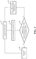
- FIG. 2 a control methodology for regulating air flow through the internal combustion engine system 10 will be discussed in which surge in the second booster 200 is identified and addressed.
- the routine reflected in FIG. 2 may be executed based on instructions and logic programmed into the controller 500, and the receipt of data from the sensor(s) 600 discussed above.
- step “A” various operating conditions are estimated and/or measured by the sensor(s) 600, such as the charge in the battery 210, pressure at the inlet 204 of the compressor 202, pressure at the outlet 206 of the compressor 202, etc.
- Data collected by the sensor(s) 600 is then communicated to the controller 500 at step “B”, and the controller 500 evaluates whether surge is either likely to occur, or whether the compressor 202 is presently experiencing surge at step “C". If it is determined by the controller 500 that the compressor 202 is not experiencing surge or that the compressor 202 is not likely to experience surge, the position of the valve 300 can be maintained in (or returned to) the fully closed position at step "E", and the routine then repeats steps "A"-"C" to continually monitor the conditions of the engine 12.
- the controller 500 can transmit a signal to the valve 300 at step “D” to transition the valve 300 from the fully closed position to one of the partially open conditions.
- the controller 500 and the sensors 600 may continually monitor the conditions of the engine 12 by repeating steps "A"-"C” to determine whether surge was successfully addressed by opening the valve 300. If it is determined that surge either has not been successfully addressed, based upon data collected by the sensor(s) 600 subsequent to initial opening of the valve 300, the controller 500 can either maintain the open position of the valve 300 or open the valve 300 further at step “D” to increase air flow into the compressor 202. Steps "A"-"C” can then be repeated to collect and process additional data until such time that the controller 500 determines that surge in the compressor 202 of the second booster 200 has been successfully addressed.
Landscapes
- Engineering & Computer Science (AREA)
- Chemical & Material Sciences (AREA)
- Combustion & Propulsion (AREA)
- Mechanical Engineering (AREA)
- General Engineering & Computer Science (AREA)
- Supercharger (AREA)
Abstract
Description
- The present disclosure relates to surge control systems and methods for internal combustion engines, and in particular, a compound boosting system of an internal combustion engine that utilizes a variable valve to adjust the amount of compressed air to the internal combustion engine to increase the power and performance of the internal combustion engine.
- Many internal combustion engine systems include boosting devices, such as turbochargers and superchargers, which compress air to increase air flow and thus improve power and performance of an internal combustion engine. However, it is well known that compressors are subject to "surge," which refers to an unstable condition in which the air pressure downstream of the compressor exceeds the pressure that the compressor can physically maintain. While surge does not typically result in catastrophic damage, it has several undesirable effects including negative air flow, compressor stall, engine noise, etc.
- Various systems and methodologies have been developed to combat compressor surge. For example, some systems utilize a dedicated recirculation valve to increase airflow. Known systems and methodologies, however, fail to disclose the use of a multifunctional valve that is operable as both a bypass valve and a recirculation valve to address surge in a compressor.
- In one aspect of the present disclosure, an engine system is disclosed that includes an engine and a compound boosting system in communication with the engine. The compound boosting system includes a first booster and a second booster positioned downstream of the first booster. A variable valve is operable as both a recirculation valve and a bypass valve wherein the variable valve is configured, dimensioned, and positioned such that, when the second booster is running, the variable valve can be moved from a closed position, wherein air flows in a single downstream direction through the second booster, to an open position, wherein air flows downstream through the second booster and upstream through the variable valve such that air is recirculated from adjacent an outlet of the second booster to an inlet of the second booster through the variable valve to mitigate surge, or a likelihood of surge, in the second booster.
- In certain embodiments, the first booster is configured as a turbine-driven booster, and the second booster is configured as an electric booster.
- In certain embodiments, the first booster is configured as a turbocharger, and the second booster is configured as a supercharger.
- In certain embodiments, the first booster includes a first compressor positioned in a flow path of incoming air, wherein the first compressor has an inlet and an outlet. A shaft is connected to the first compressor, and a turbine is connected to the shaft. The turbine is positioned in a flow path of exhaust created by the engine such that the exhaust rotates the turbine to thereby cause rotation of the first compressor via the shaft, wherein rotation of the first compressor causes first stage compression of the incoming air.
- In certain embodiments, the second booster further includes a power source in communication with the electric motor.
- In certain embodiments, the power source is a battery.
- In certain embodiments, the engine system further includes an intercooler positioned downstream of the first booster and upstream of the second booster.
- In certain embodiments, the engine systems includes the variable drive movable between a fully closed position and one or more open positions.
- In certain embodiments, the engine system may further include the variable valve configured, dimensioned, and positioned such that in the open positions, when the second booster is not running, compressed air exiting the first booster can flow into the engine: (i) through the second booster; and/or (ii) around the second booster.
- In certain embodiments, the engine system may further include the variable valve configured, dimensioned, and positioned such that in the fully closed position, when the second booster is running, compressed air exiting the first booster flows into the second booster for additional compression before flowing into the engine.
- In certain embodiments, the engine system may further include the variable valve configured, dimensioned, and positioned for movement between a first partially open position and a second partially open position, wherein air flow through the variable valve is greater in the second partially open position.
- In another aspect of the present disclosure, an engine system is disclosed that includes a controller in communication with the variable valve to vary a position of the variable valve and thereby regulate air flow through the variable valve and into the engine.
- In certain embodiments, the engine system further includes one or more sensors in communication with the controller, the one or more sensors being adapted to collect and transmit data to the controller including information concerning operating conditions of the engine system, the controller being adapted and programmed to: (i) process the data received from the one or more sensors to determine whether surge has occurred or is likely to occur in the second booster; and (ii) transmit a signal to the variable valve to move the variable valve from the closed position to open position to facilitate air recirculation from adjacent the outlet of the second booster to the inlet of the second booster through the variable valve.
- The disclosure is best understood from the following detailed description when read in conjunction with the accompanying drawings. It is emphasized that, according to common practice, the various features of the drawings are not to-scale. On the contrary, the dimensions of the various features are arbitrarily expanded or reduced for clarity.
-
FIG. 1 is a schematic view of an engine system including a turbine-driven compressor an electric compressor positioned downstream of the turbine-driven compressor in accordance with the principles of the present disclosure; and -
FIG. 2 illustrates a flow chart for a routine that may be executed to reduce surge in the electric compressor. - Various embodiments of the present disclosure will now be described in detail with reference to the figures, wherein like references numerals identify similar or identical elements. With reference now to
FIG. 1 , an internalcombustion engine system 10 is disclosed that includes, among other components, aninternal combustion engine 12, acompound boosting system 1000 including a first, turbine-drivenbooster 100 and a second,electric booster 200, such as the eBooster® made available by Borg Warner, and avariable valve 300. It is also envisioned that thesystem 10 may include anoptional intercooler 400, such as an air-to-air or air-to-water heat exchanger. The turbine-drivenbooster 100 provides a first stage compression to incoming air, and theelectric booster 200 provides optional a second stage compression prior to the flow of air into theengine 12. As discussed below, thevariable valve 300 is configured, dimensioned, and positioned to modulate airflow into theelectric booster 200 in order to mitigate surge and improve the overall performance of theengine system 10. - In the embodiment of the internal
combustion engine system 10 seen inFIG. 1 , thefirst booster 100 is configured as a turbocharger of theinternal combustion engine 12, and thesecond booster 200 is configured as an electric supercharger of theinternal combustion engine 12. In alternate embodiments, however, it is envisioned that the specific configurations of theboosters - The
first booster 100 receives a flow of incoming air and is positioned upstream of thesecond booster 200. Thefirst booster 100 includes acompressor 102 having respective inlets andoutlets turbine 108, and ashaft 110 that interconnects thecompressor 102 and theturbine 108. Theturbine 108 is positioned downstream of theinternal combustion engine 12 in the path of exhaust gases produced by theengine 12 such that as theengine 12 operates, the exhaust gases produced flow into and spin theturbine 108. The rotational energy of theturbine 108 is communicated to thecompressor 102 by theshaft 110 to rotate thecompressor 102 thereby compressing the incoming flow of air after passing through anair filter 112. - The
second booster 200 includes acompressor 202 having respective inlets andoutlets first booster 100. Thesecond booster 200 is driven by anelectric motor 208, which may be powered in any suitable manner, such as by an on-board energy storage device, e.g., abattery 210, a generator, or a combination thereof. In certain embodiments, such as that illustrated inFIG. 1 , thesecond booster 200 may be positioned downstream of thefirst booster 100 such that compressed air exiting thefirst booster 100 may be optionally subjected to additional compression, for example, dependent upon the demand placed on theengine 12, as will be discussed in further detail below. - With continued reference to
FIG. 1 , thevalve 300 is a continuously variable, multifunctional valve that is operable as both a bypass valve and a recirculation valve movable between a fully open position, a fully closed position, and one or more partially open positions. When thevalve 300 is open, thevalve 300 acts as a conduit through which air flows. For example, when thesecond booster 200 is not in operation, compressed air exiting thefirst booster 100 is allowed to flow through thevalve 300 in the direction indicated by arrow 2, around thesecond booster 200, and enter theengine 12 directly. Thus, in the open position(s), thevalve 300 performs generally as a bypass valve allowing air to be diverted around thesecond booster 200. While it is envisioned that a portion of the air exiting thefirst booster 100 may flow through thesecond booster 200 when thesecond booster 200 is not in operation, the open conduit provided by thevalve 300 offers far less restriction on air flow. By contrast, when thesecond booster 200 is in operation, thevalve 300 can be fully closed to ensure that air exiting thefirst booster 100 is directed/drawn into the second booster 200 (in the direction indicated by arrow 1) for additional, second stage compression before flowing into theengine 12 in the direction indicated by arrow 3. - The ability to reposition the
valve 300 between a plurality of open position(s) allows air flow through thevalve 300 to be regulated. More specifically, air flow can be progressively increased or decreased to augment or reduce the amount of air flowing through thevalve 300, for example, based upon desired performance of theengine 12 or surge conditions, as discussed below. - Under certain operating conditions, air flow through the
second booster 200 may be reduced, potentially resulting in surge conditions that can degrade performance of thecompressor 202, and consequently, theengine 12. Such conditions typically occur during high power/low flow operation, such as, for example, during a hard acceleration or during operation of theengine 12 in an improperly high gear in the transmission (not shown). During surge conditions, due to the low flow of air into thecompressor 202, pressure at theoutlet 206 exceeds pressure at theinlet 204 to such an extent that a reversal of air flow through thecompressor 202 can occur in which air attempts to flows "upstream" through thecompressor 202 from the area of higher pressure (at the outlet 206) to the area of lower pressure (at the inlet 204). To mitigate the negative impact of such a flow reversal, thevalve 300 can be moved into one of the open positions in order to redirect and recirculate the air flowing "upstream" into theinlet 204 of thecompressor 202. More specifically, by opening thevalve 300, an alternate path is created that allows air to be recirculated for flow into the inlet 204 (in the direction indicated by arrow 4) to increase pressure at theinlet 204. By increasing pressure at theinlet 204, the pressure differential at theoutlet 206 and theinlet 204 can be reduced, thereby mitigate surge. During such operation, as thevalve 300 moves from the closed position to one of the open positions, the role played by thevalve 300 thus changes from one of bypass to one of recirculation. - To monitor, evaluate, and combat surge conditions, the
engine system 10 may include acontroller 500 and one ormore sensors 600. Thecontroller 500 is adapted and programmed to receive data from the sensor(s) 600, process the data, and transmit signals to carry out various tasks, such as one or more routines programmed into the logic of thecontroller 500 to perform certain functions. For example, based on the data collected by the sensor(s) 600 and the calculations performed by thecontroller 500, thecontroller 500 may vary operation of theengine 12, activate or deactivate thesecond booster 200, transmit a signal to vary the position of thevalve 300 between the closed position and one of the open positions, thereby altering the flow of air through thesecond booster 200, etc. - The sensor(s) 600 included in the internal
combustion engine system 10 may include several varieties and may be positioned in various locations to collect data pertaining to the operating conditions of the internalcombustion engine system 10. For example, the internalcombustion engine system 10 may include one ormore sensors 600 to measure or estimate temperature at therespective inlets compressors respective outlets compressors engine 12, to measure the levels of humidity, engine speed, fueling, load, etc. - After receiving data collected by the sensor(s) 600, the
controller 500 can process the data to vary operation of the internalcombustion engine system 10. For example, in one set of operating conditions, as theengine 12 runs, the exhaust gases build up and ultimately act on theturbine 108 of thefirst booster 100. However, in the interval of time between the initiation of engine operation and the initiation of spin in theturbine 108, there may be a delay in the communication of energy to thecompressor 102 of thefirst booster 100, commonly referred to a "turbo lag." To compensate for this delay and reduce or minimize the impact upon performance of the internalcombustion engine system 10, thecontroller 500 may transmit a signal to actuate thesecond booster 200 to increase the pressure and compression of air entering theengine 12 while thecompressor 102 comes up to speed based upon the pressure measured by asensor 600 at theoutlet 106 of thecompressor 102 of thefirst booster 100. During such operation, thecontroller 500 may close thevalve 300 such that air is directed into thesecond booster 200 prior to entering theengine 12. However, after theturbine 108 of thefirst booster 100 has achieved sufficient rotational speed in order to generate adequate compression by thecompressor 102, as measured by asensor 600 at theoutlet 106 of thecompressor 102, thecontroller 500 may either deactivate thesecond booster 200 and open thevalve 300 such that air compressed by thefirst booster 100 passes directly into theengine 12, or alternatively, thecontroller 500 may maintain the closed position of thevalve 300 such that air exiting thecompressor 102 of thefirst booster 100 undergoes a second stage of compression by thebooster 206 to further increase the power produced by theengine 12. - During operation of the
engine 12, the position of thevalve 300 can be continually varied by thecontroller 500 depending on the operating conditions measured by the sensor(s) 600. When thecontroller 500 recognizes surge, or conditions that may result in surge, thecontroller 500 can vary the exact position of thevalve 300, for example, by moving thevalve 300 from the closed position to one of the open positions, or by increasing the opening of the valve, in order to control air flow into thesecond booster 200 based on data collected by thesensors 600 relating to compressor ratio, compressor flow rate, pressure differentials, etc. When pressure measured at theoutlet 206 of thesecond booster 200 exceeds pressure measured at theinlet 204 by a certain amount or percentage, such as a ratio within the range of 1.25 to 3 or more, thecontroller 500 can open thevalve 300 to permit the recirculation of air into theinlet 204 to reduce the pressure differential, as discussed above. When surge or surge conditions are not identified by thecontroller 500, however, such as when pressures at theoutlet 206 and theinlet 204 are within a certain tolerance, for example, thevalve 300 may remain closed such that air is continuously drawn into thesecond booster 200. Thecontroller 500 may thus be programmed to vary functionality of thevalve 300 between bypass and recirculation operations. - Dependent upon the particular operating conditions, it is envisioned that the
controller 500 may open thevalve 300 such that air, or a portion of the air, bypasses thesecond booster 200 to thereby limit compression in order to achieve a particular output by theengine 12. It is also envisioned that thecontroller 500 may close thevalve 300 to maximize air flow into thesecond booster 200 to increase compression and power generated by theengine 12. - With reference to
FIG. 2 , a control methodology for regulating air flow through the internalcombustion engine system 10 will be discussed in which surge in thesecond booster 200 is identified and addressed. The routine reflected inFIG. 2 may be executed based on instructions and logic programmed into thecontroller 500, and the receipt of data from the sensor(s) 600 discussed above. - At step "A", various operating conditions are estimated and/or measured by the sensor(s) 600, such as the charge in the
battery 210, pressure at theinlet 204 of thecompressor 202, pressure at theoutlet 206 of thecompressor 202, etc. Data collected by the sensor(s) 600 is then communicated to thecontroller 500 at step "B", and thecontroller 500 evaluates whether surge is either likely to occur, or whether thecompressor 202 is presently experiencing surge at step "C". If it is determined by thecontroller 500 that thecompressor 202 is not experiencing surge or that thecompressor 202 is not likely to experience surge, the position of thevalve 300 can be maintained in (or returned to) the fully closed position at step "E", and the routine then repeats steps "A"-"C" to continually monitor the conditions of theengine 12. However, if it is determined by thecontroller 500 at step "C" that thecompressor 202 is either presently experiencing surge or that thecompressor 202 is likely to experience surge, thecontroller 500 can transmit a signal to thevalve 300 at step "D" to transition thevalve 300 from the fully closed position to one of the partially open conditions. Following repositioning of thevalve 300, thecontroller 500 and thesensors 600 may continually monitor the conditions of theengine 12 by repeating steps "A"-"C" to determine whether surge was successfully addressed by opening thevalve 300. If it is determined that surge either has not been successfully addressed, based upon data collected by the sensor(s) 600 subsequent to initial opening of thevalve 300, thecontroller 500 can either maintain the open position of thevalve 300 or open thevalve 300 further at step "D" to increase air flow into thecompressor 202. Steps "A"-"C" can then be repeated to collect and process additional data until such time that thecontroller 500 determines that surge in thecompressor 202 of thesecond booster 200 has been successfully addressed. - Persons skilled in the art will understand that the various embodiments of the disclosure described herein, and shown in the accompanying figures, constitute non-limiting examples, and that additional components and features may be added to any of the embodiments discussed herein above without departing from the scope of the present disclosure. Additionally, persons skilled in the art will understand that the elements and features shown or described in connection with one embodiment may be combined with those of another embodiment without departing from the scope of the present disclosure and will appreciate further features and advantages of the presently disclosed subject matter based on the description provided. Variations, combinations, and/or modifications to any of the embodiments and/or features of the embodiments described herein within the abilities of a person having ordinary skill in the art are also within the scope of the disclosure, as are alternative embodiments that may result from combining, integrating, and/or omitting features from any of the disclosed embodiments. For example, in alternate embodiments, the inclusion, order, and arrangement of the components discussed herein may be varied. For instance, in alternate embodiments, the second (electric)
booster 200 may be located upstream of thefirst booster 100, the location of theintercooler 400 may be varied, or theintercooler 400 and/or thefirst booster 100 may be eliminated altogether.
Claims (15)
- An engine system (10), comprising:an engine (12);a compound boosting system (1000) in communication with the engine (12), the compound boosting system (1000) including a first booster (100), and a second booster (200) positioned downstream of the first booster (100); anda variable valve (300) operable as both a recirculation valve and a bypass valve, the variable valve (300) being configured, dimensioned, and positioned such that, when the second booster (200) is running, the variable valve (300) can be moved from a closed position, wherein air flows in a single downstream direction through the second booster (200), to an open position, wherein air flows downstream through the second booster (200) and upstream through the variable valve (300) such that air is recirculated from adjacent an outlet (206) of the second booster (200) to an inlet (204) of the second booster (200) through the variable valve (300) to mitigate surge, or a likelihood of surge, in the second booster (200).
- The engine system (10) of claim 1, wherein the first booster (100) is configured as a turbine-driven booster and the second booster (200) is configured as an electric booster.
- The engine system (10) according to any preceding claim, wherein the first booster (100) is configured as a turbocharger, and the second booster (200) is configured as a supercharger.
- The engine system (10) according to any preceding claim, wherein the first booster (100) includes:a first compressor (102) positioned in a flow path of incoming air, the first compressor (102) having an inlet (104) and an outlet (106);a shaft (110) connected to the first compressor (102); anda turbine (108) connected to the shaft (110), the turbine (108) being positioned in a flow path of exhaust created by the engine (12) such that the exhaust rotates the turbine (108) to thereby cause rotation of the first compressor (102) via the shaft (110), wherein rotation of the first compressor (102) causes first stage compression of the incoming air.
- The engine system (10) of claim 4, wherein the second booster (200) includes:a second compressor (202); andan electric motor (208) in communication with the second compressor (202) to rotate the second compressor to cause second stage compression of compressed air exiting the first booster (100).
- The engine system (10) of claim 5, wherein the second booster (200) further includes a power source (210) in communication with the electric motor (208).
- The engine system (10) of claim 6, wherein the power source (210) is a battery.
- The engine system (10) according to any preceding claim, further including an intercooler (400) positioned downstream of the first booster (100) and upstream of the second booster (200).
- The engine system (10) according to any preceding claim, wherein the variable valve (300) is positioned in a flow path of compressed air exiting the first booster (100).
- The engine system (10) according to any preceding claim, wherein the variable valve (300) is movable between a fully closed position, and one or more open positions.
- The engine system (10) of claim 10, wherein the variable valve (300) is configured, dimensioned, and positioned such that in the open positions, when the second booster (200) is not running, compressed air exiting the first booster (100) can flow into the engine (12): (i) through the second booster (200); and/or (ii) around the second booster (200).
- The engine system (10) according to claims 10 or 11, wherein the variable valve (300) is configured, dimensioned, and positioned such that in the fully closed position, when the second booster (200) is running, compressed air exiting the first booster (100) flows into the second booster (200) for additional compression before flowing into the engine (12).
- The engine system (10) according to any of claims 10 to 12, wherein the variable valve (300) is configured, dimensioned, and positioned for movement between a first partially open position and a second partially open position, wherein air flow through the variable valve (300) is greater in the second partially open position.
- The engine system (10) according to any preceding claim, further including a controller (500) in communication with the variable valve (300) to vary a position of the variable valve (300) and thereby regulate air flow through the variable valve (300) and into the engine (12).
- The engine system (10) according to claim 14, further including one or more sensors (600) in communication with the controller (500), the one or more sensors (600) being adapted to collect and transmit data to the controller (500) including information concerning operating conditions of the engine system (10), the controller (500) being adapted and programmed to: (i) process the data received from the one or more sensors (600) to determine whether surge has occurred or is likely to occur in the second booster (200); and (ii) transmit a signal to the variable valve (300) to move the variable valve (300) from the closed position to open position to facilitate air recirculation from adjacent the outlet (206) of the second booster (200) to the inlet (204) of the second booster (200) through the variable valve (300).
Applications Claiming Priority (1)
| Application Number | Priority Date | Filing Date | Title |
|---|---|---|---|
| US15/896,297 US20190249595A1 (en) | 2018-02-14 | 2018-02-14 | System and Method for Controlling Compressor Surge |
Publications (1)
| Publication Number | Publication Date |
|---|---|
| EP3561259A1 true EP3561259A1 (en) | 2019-10-30 |
Family
ID=65433521
Family Applications (1)
| Application Number | Title | Priority Date | Filing Date |
|---|---|---|---|
| EP19156798.1A Withdrawn EP3561259A1 (en) | 2018-02-14 | 2019-02-12 | System and method for preventing the compressor surge in an internal combustion engine provided with two compressors |
Country Status (2)
| Country | Link |
|---|---|
| US (1) | US20190249595A1 (en) |
| EP (1) | EP3561259A1 (en) |
Families Citing this family (2)
| Publication number | Priority date | Publication date | Assignee | Title |
|---|---|---|---|---|
| CN111350583A (en) * | 2018-12-21 | 2020-06-30 | 博格华纳公司 | Turbocharger for an internal combustion engine |
| US11639703B1 (en) * | 2022-06-21 | 2023-05-02 | Garrett Transportation I Inc. | System and method using secondary air pump for secondary air injection into turbocharged internal combustion engine exhaust and for transiently augmenting engine boost pressure, including means for supressing surge of the secondary air pump |
Citations (4)
| Publication number | Priority date | Publication date | Assignee | Title |
|---|---|---|---|---|
| DE102010027220A1 (en) * | 2010-07-15 | 2012-01-19 | Volkswagen Ag | Method for starting internal combustion engine mounted in motor vehicle, involves pumping combustion air over bypass pipe bridging compressor in combustion air channel before initiating combustion process |
| EP2767701A1 (en) * | 2013-02-19 | 2014-08-20 | The Boeing Company | Air charge system and method for an internal combustion engine |
| US20170130658A1 (en) * | 2015-11-10 | 2017-05-11 | Ford Global Technologies, Llc | Vacuum control via a compressor bypass valve in a twin-compressor engine system |
| EP3279454A1 (en) * | 2016-08-05 | 2018-02-07 | Toyota Jidosha Kabushiki Kaisha | Control device for internal combustion engine |
Family Cites Families (2)
| Publication number | Priority date | Publication date | Assignee | Title |
|---|---|---|---|---|
| CN106065809B (en) * | 2015-04-24 | 2020-12-25 | 福特环球技术公司 | Engine with two-stage supercharging and exhaust gas aftertreatment and method for operating the same |
| US9726092B2 (en) * | 2015-11-16 | 2017-08-08 | Ford Global Technologies, Llc | Methods and systems for boost control |
-
2018
- 2018-02-14 US US15/896,297 patent/US20190249595A1/en not_active Abandoned
-
2019
- 2019-02-12 EP EP19156798.1A patent/EP3561259A1/en not_active Withdrawn
Patent Citations (4)
| Publication number | Priority date | Publication date | Assignee | Title |
|---|---|---|---|---|
| DE102010027220A1 (en) * | 2010-07-15 | 2012-01-19 | Volkswagen Ag | Method for starting internal combustion engine mounted in motor vehicle, involves pumping combustion air over bypass pipe bridging compressor in combustion air channel before initiating combustion process |
| EP2767701A1 (en) * | 2013-02-19 | 2014-08-20 | The Boeing Company | Air charge system and method for an internal combustion engine |
| US20170130658A1 (en) * | 2015-11-10 | 2017-05-11 | Ford Global Technologies, Llc | Vacuum control via a compressor bypass valve in a twin-compressor engine system |
| EP3279454A1 (en) * | 2016-08-05 | 2018-02-07 | Toyota Jidosha Kabushiki Kaisha | Control device for internal combustion engine |
Also Published As
| Publication number | Publication date |
|---|---|
| US20190249595A1 (en) | 2019-08-15 |
Similar Documents
| Publication | Publication Date | Title |
|---|---|---|
| US9874138B2 (en) | Twin scroll turbocharger device with bypass | |
| JP4680472B2 (en) | Internal combustion engine-turbosupercharger unit for motor vehicles with turbine power control, in particular industrial vehicles | |
| EP1472444B1 (en) | Turbocharging system and a method for turbocharging of an internal combustion engine | |
| US6263673B1 (en) | Method for operating a supercharged internal combustion engine and device for this purpose | |
| EP2049780B1 (en) | Control method for turbocharger and clutch coupled supercharger | |
| US9291092B2 (en) | Turbine for an exhaust gas turbocharger | |
| US20160312687A1 (en) | Internal combustion engine with two-stage supercharging capability and with exhaust-gas aftertreatment arrangement, and method for operating an internal combustion engine of said type | |
| US20150050128A1 (en) | Compact multi-stage turbo pump | |
| GB2156429A (en) | Control of i.c. engine plural turbocharger systems | |
| JPS6353364B2 (en) | ||
| CN107002599A (en) | Operating method for the supercharging device of explosive motor and for the supercharging device | |
| CN106795805A (en) | Supercharging equipment for explosive motor and the operating method for supercharging equipment | |
| CN104968925A (en) | Internal combustion engine comprising a booster | |
| US20030115870A1 (en) | Exhaust-gas turbocharger in an internal combustion engine | |
| JPS5982526A (en) | Supercharger for internal-combustion engine | |
| US20190249595A1 (en) | System and Method for Controlling Compressor Surge | |
| US8646433B2 (en) | Arrangement for exhaust braking of a combustion engine | |
| CN104302888A (en) | Exhaust turbocharger having a wastegate valve and a thrust circulation valve | |
| JPH0530967B2 (en) | ||
| SU1658824A3 (en) | Ship multiengined propulsion system | |
| WO2016124445A1 (en) | A multi-stage exhaust turbocharger system | |
| EP1482128A1 (en) | Supercharged Internal combustion engine | |
| US11629612B2 (en) | System for feeding operating gas to a drive of a motor vehicle | |
| KR100774349B1 (en) | Variable Speed Compression Supercharging System Using Planetary Gears | |
| JPH0454221A (en) | Supercharging device for engine |
Legal Events
| Date | Code | Title | Description |
|---|---|---|---|
| APBK | Appeal reference recorded |
Free format text: ORIGINAL CODE: EPIDOSNREFNE |
|
| APBN | Date of receipt of notice of appeal recorded |
Free format text: ORIGINAL CODE: EPIDOSNNOA2E |
|
| APBR | Date of receipt of statement of grounds of appeal recorded |
Free format text: ORIGINAL CODE: EPIDOSNNOA3E |
|
| APBV | Interlocutory revision of appeal recorded |
Free format text: ORIGINAL CODE: EPIDOSNIRAPE |
|
| PUAI | Public reference made under article 153(3) epc to a published international application that has entered the european phase |
Free format text: ORIGINAL CODE: 0009012 |
|
| STAA | Information on the status of an ep patent application or granted ep patent |
Free format text: STATUS: THE APPLICATION HAS BEEN PUBLISHED |
|
| AK | Designated contracting states |
Kind code of ref document: A1 Designated state(s): AL AT BE BG CH CY CZ DE DK EE ES FI FR GB GR HR HU IE IS IT LI LT LU LV MC MK MT NL NO PL PT RO RS SE SI SK SM TR |
|
| AX | Request for extension of the european patent |
Extension state: BA ME |
|
| STAA | Information on the status of an ep patent application or granted ep patent |
Free format text: STATUS: THE APPLICATION IS DEEMED TO BE WITHDRAWN |
|
| 18D | Application deemed to be withdrawn |
Effective date: 20200603 |