EP3561246A1 - Straddled vehicle - Google Patents
Straddled vehicle Download PDFInfo
- Publication number
- EP3561246A1 EP3561246A1 EP19168292.1A EP19168292A EP3561246A1 EP 3561246 A1 EP3561246 A1 EP 3561246A1 EP 19168292 A EP19168292 A EP 19168292A EP 3561246 A1 EP3561246 A1 EP 3561246A1
- Authority
- EP
- European Patent Office
- Prior art keywords
- cover
- vehicle
- sensor
- oxygen sensor
- width direction
- Prior art date
- Legal status (The legal status is an assumption and is not a legal conclusion. Google has not performed a legal analysis and makes no representation as to the accuracy of the status listed.)
- Granted
Links
Images







Classifications
-
- F—MECHANICAL ENGINEERING; LIGHTING; HEATING; WEAPONS; BLASTING
- F01—MACHINES OR ENGINES IN GENERAL; ENGINE PLANTS IN GENERAL; STEAM ENGINES
- F01N—GAS-FLOW SILENCERS OR EXHAUST APPARATUS FOR MACHINES OR ENGINES IN GENERAL; GAS-FLOW SILENCERS OR EXHAUST APPARATUS FOR INTERNAL-COMBUSTION ENGINES
- F01N1/00—Silencing apparatus characterised by method of silencing
-
- F—MECHANICAL ENGINEERING; LIGHTING; HEATING; WEAPONS; BLASTING
- F01—MACHINES OR ENGINES IN GENERAL; ENGINE PLANTS IN GENERAL; STEAM ENGINES
- F01N—GAS-FLOW SILENCERS OR EXHAUST APPARATUS FOR MACHINES OR ENGINES IN GENERAL; GAS-FLOW SILENCERS OR EXHAUST APPARATUS FOR INTERNAL-COMBUSTION ENGINES
- F01N13/00—Exhaust or silencing apparatus characterised by constructional features
- F01N13/008—Mounting or arrangement of exhaust sensors in or on exhaust apparatus
-
- F—MECHANICAL ENGINEERING; LIGHTING; HEATING; WEAPONS; BLASTING
- F01—MACHINES OR ENGINES IN GENERAL; ENGINE PLANTS IN GENERAL; STEAM ENGINES
- F01P—COOLING OF MACHINES OR ENGINES IN GENERAL; COOLING OF INTERNAL-COMBUSTION ENGINES
- F01P11/00—Component parts, details, or accessories not provided for in, or of interest apart from, groups F01P1/00 - F01P9/00
- F01P11/10—Guiding or ducting cooling-air, to, or from, liquid-to-air heat exchangers
-
- F—MECHANICAL ENGINEERING; LIGHTING; HEATING; WEAPONS; BLASTING
- F01—MACHINES OR ENGINES IN GENERAL; ENGINE PLANTS IN GENERAL; STEAM ENGINES
- F01P—COOLING OF MACHINES OR ENGINES IN GENERAL; COOLING OF INTERNAL-COMBUSTION ENGINES
- F01P5/00—Pumping cooling-air or liquid coolants
- F01P5/02—Pumping cooling-air; Arrangements of cooling-air pumps, e.g. fans or blowers
- F01P5/06—Guiding or ducting air to, or from, ducted fans
-
- F—MECHANICAL ENGINEERING; LIGHTING; HEATING; WEAPONS; BLASTING
- F01—MACHINES OR ENGINES IN GENERAL; ENGINE PLANTS IN GENERAL; STEAM ENGINES
- F01N—GAS-FLOW SILENCERS OR EXHAUST APPARATUS FOR MACHINES OR ENGINES IN GENERAL; GAS-FLOW SILENCERS OR EXHAUST APPARATUS FOR INTERNAL-COMBUSTION ENGINES
- F01N2260/00—Exhaust treating devices having provisions not otherwise provided for
- F01N2260/20—Exhaust treating devices having provisions not otherwise provided for for heat or sound protection, e.g. using a shield or specially shaped outer surface of exhaust device
-
- F—MECHANICAL ENGINEERING; LIGHTING; HEATING; WEAPONS; BLASTING
- F01—MACHINES OR ENGINES IN GENERAL; ENGINE PLANTS IN GENERAL; STEAM ENGINES
- F01N—GAS-FLOW SILENCERS OR EXHAUST APPARATUS FOR MACHINES OR ENGINES IN GENERAL; GAS-FLOW SILENCERS OR EXHAUST APPARATUS FOR INTERNAL-COMBUSTION ENGINES
- F01N2560/00—Exhaust systems with means for detecting or measuring exhaust gas components or characteristics
- F01N2560/02—Exhaust systems with means for detecting or measuring exhaust gas components or characteristics the means being an exhaust gas sensor
- F01N2560/025—Exhaust systems with means for detecting or measuring exhaust gas components or characteristics the means being an exhaust gas sensor for measuring or detecting O2, e.g. lambda sensors
-
- F—MECHANICAL ENGINEERING; LIGHTING; HEATING; WEAPONS; BLASTING
- F01—MACHINES OR ENGINES IN GENERAL; ENGINE PLANTS IN GENERAL; STEAM ENGINES
- F01N—GAS-FLOW SILENCERS OR EXHAUST APPARATUS FOR MACHINES OR ENGINES IN GENERAL; GAS-FLOW SILENCERS OR EXHAUST APPARATUS FOR INTERNAL-COMBUSTION ENGINES
- F01N2590/00—Exhaust or silencing apparatus adapted to particular use, e.g. for military applications, airplanes, submarines
- F01N2590/04—Exhaust or silencing apparatus adapted to particular use, e.g. for military applications, airplanes, submarines for motorcycles
-
- F—MECHANICAL ENGINEERING; LIGHTING; HEATING; WEAPONS; BLASTING
- F01—MACHINES OR ENGINES IN GENERAL; ENGINE PLANTS IN GENERAL; STEAM ENGINES
- F01N—GAS-FLOW SILENCERS OR EXHAUST APPARATUS FOR MACHINES OR ENGINES IN GENERAL; GAS-FLOW SILENCERS OR EXHAUST APPARATUS FOR INTERNAL-COMBUSTION ENGINES
- F01N2900/00—Details of electrical control or of the monitoring of the exhaust gas treating apparatus
- F01N2900/06—Parameters used for exhaust control or diagnosing
- F01N2900/14—Parameters used for exhaust control or diagnosing said parameters being related to the exhaust gas
- F01N2900/1402—Exhaust gas composition
-
- F—MECHANICAL ENGINEERING; LIGHTING; HEATING; WEAPONS; BLASTING
- F01—MACHINES OR ENGINES IN GENERAL; ENGINE PLANTS IN GENERAL; STEAM ENGINES
- F01P—COOLING OF MACHINES OR ENGINES IN GENERAL; COOLING OF INTERNAL-COMBUSTION ENGINES
- F01P2050/00—Applications
- F01P2050/16—Motor-cycles
Definitions
- the present invention relates to a straddled vehicle.
- a straddled vehicle known to date includes an oxygen sensor for detecting an oxygen concentration of an exhaust gas.
- the oxygen sensor includes a sensor element including a material such as zirconia. To detect the oxygen concentration accurately, the temperature of the sensor element needs to be maintained at a predetermined activation temperature.
- JP 2009-226988 A describes a motorcycle in which an oxygen sensor is attached to a portion of an exhaust pipe located rearward of a fan cover.
- the fan cover accommodates a fan, and the fan cover has openings through which air is introduced.
- a fan cover has openings through which air is introduced.
- the fan cover is disposed at such a position that the flowing air passes around the fan cover in order to facilitate introduction of air during traveling of the motorcycle.
- the oxygen sensor is readily cooled by the flowing air.
- the oxygen sensor incorporates a heater, a detection accuracy of the oxygen sensor might decrease.
- an inventor of the present application tried to form a sensor cover for hindering blowing of flowing air to the oxygen sensor integrally with the fan cover.
- the sensor cover is formed integrally with a rear portion of the fan cover so that the sensor cover overlaps at least a portion of the oxygen sensor in a vehicle side view.
- a portion of the sensor cover overlapping the oxygen sensor is formed to project outward in a vehicle width direction toward the rear. This configuration was expected to prevent direct blowing of flowing air to the oxygen sensor and to smoothly guide the flowing air rearward.
- the inventor further studied as follows. First, the inventor tried to increase the size of the sensor cover such that the sensor cover extends rearward. However, when the size of the sensor cover is increased, a force exerted on the sensor cover from flowing air increases. Thus, this idea is not favorable in terms of obtaining rigidity of the sensor cover and the fan cover integrated with the sensor cover.
- a straddled vehicle disclosed here includes: an internal combustion engine; an exhaust pipe connected to the internal combustion engine; a silencer disposed rearward of the exhaust pipe and connected to the exhaust pipe; a fan disposed outward of the internal combustion engine in a vehicle width direction; a fan cover disposed outward of the fan in the vehicle width direction and having an opening; a silencer cover disposed outward of the silencer in the vehicle width direction; an oxygen sensor including a sensor element disposed inside the exhaust pipe and a heater that heats the sensor element, the oxygen sensor being attached to the exhaust pipe; and a sensor cover integrally formed with the fan cover, located outward of the oxygen sensor in the vehicle width direction, overlapping at least a portion of the oxygen sensor in a vehicle side view, and extending outward in the vehicle width direction and rearward in a vehicle fore-and-aft direction.
- the silencer cover has a front portion located outward of the oxygen sensor in the vehicle width direction and extending outward in the vehicle width direction and rearward in the vehicle fore-and-aft direction.
- a distance between a rear end of the sensor cover and a front end of the front portion of the silencer cover in the vehicle fore-and-aft direction is smaller than a distance between a rear end of the fan cover and a front end of the silencer.
- the lower extension cover 62 includes an upper edge portion 62a and a lower edge portion 62b each extending rearward, and a rear edge portion 62c extending from the rear end of the upper edge portion 62a to the rear end of the lower edge portion 62b.
- the rear edge portion 62c includes an upper portion 62c1 extending forward and downward from the rear end of the upper edge portion 62a and a lower portion 62c2 extending forward and upward from the rear end of the lower edge portion 62b.
- the rear edge portion 62c is recessed forward.
- the second oxygen sensor 50 is disposed rearward of the internal combustion engine 11A of the engine unit 10. As illustrated in FIG. 7 , at least a portion of the second oxygen sensor 50 overlaps the rear wheel 36 in a vehicle side view.
- a portion of the lower extension cover 62 overlaps at least a portion of the second oxygen sensor 50 in a vehicle side view.
- the portion of the lower extension cover 62 constitutes a sensor cover 65.
- the sensor cover 65 is disposed rearward of the openings 17a and 17b of the fan cover 61.
- the sensor cover 65 is located outward of the second oxygen sensor 50 in the vehicle width direction.
- the lower extension cover 62 extends outward in the vehicle width direction and rearward in the vehicle fore-and-aft direction.
- the sensor cover 65 also extends outward in the vehicle width direction and rearward in the vehicle fore-and-aft direction.
- the second oxygen sensor 50 is disposed near the fan cover 61.
- flowing air W1 that has flowed along the fan cover 61 flows toward the second oxygen sensor 50 to cool the second oxygen sensor 50.
- the second oxygen sensor 50 incorporates the heater 53 (see FIG. 9 )
- the temperature of the sensor element 51 decreases so that a detection accuracy might decrease.
- a flow of flowing air toward the second oxygen sensor 50 is suppressed so that cooling of the second oxygen sensor 50 by flowing air is suppressed. Accordingly, temperature of the sensor element 51 is suppressed to decrease so that accuracy of the second oxygen sensor 50 can be kept sufficiently high.
- the second wire 46 has a portion 46a disposed above the fan 16 and inward of the fan cover 61 in the vehicle width direction and extending forward. Accordingly, the second wire 46 is easily routed.
- the sensor cover 65 overlaps the wire connection portion 55 of the second oxygen sensor 50 in the vehicle side view, but is not limited to a specific positional relationship.
- the sensor cover 65 may not overlap a portion of the second oxygen sensor 50 in the vehicle side view or whole second oxygen sensor 50 in the vehicle side view.
- a straddled vehicle as used herein refers to a vehicle on which a rider sits astride.
- the straddled vehicle is not limited to the scooter 1.
- the straddled vehicle may be a motorcycle of another type.
- the straddled vehicle may be a vehicle other than a motorcycle, such as a motor tricycle or an all terrain vehicle (ATV) .
- ATV all terrain vehicle
Landscapes
- Engineering & Computer Science (AREA)
- Chemical & Material Sciences (AREA)
- Combustion & Propulsion (AREA)
- Mechanical Engineering (AREA)
- General Engineering & Computer Science (AREA)
- Analytical Chemistry (AREA)
- Exhaust Silencers (AREA)
- Exhaust Gas After Treatment (AREA)
- Measuring Oxygen Concentration In Cells (AREA)
Abstract
Description
- The present invention relates to a straddled vehicle.
- A straddled vehicle known to date includes an oxygen sensor for detecting an oxygen concentration of an exhaust gas. The oxygen sensor includes a sensor element including a material such as zirconia. To detect the oxygen concentration accurately, the temperature of the sensor element needs to be maintained at a predetermined activation temperature.
-
JP 2009-226988 A - In a configuration in which an oxygen sensor is disposed near a combustion chamber of an engine, a sensor element can be quickly warmed by a high-temperature exhaust gas from the combustion chamber. In addition, the sensor element can be easily maintained at a predetermined temperature. However, as described in
JP 2009-226988 A JP 2009-226988 A - While a motorcycle is traveling, air flows from the front toward the rear in the motorcycle. This air will be hereinafter referred to as "flowing air." A fan cover has openings through which air is introduced. The fan cover is disposed at such a position that the flowing air passes around the fan cover in order to facilitate introduction of air during traveling of the motorcycle. Thus, in a configuration where the oxygen sensor is disposed near the fan cover, the oxygen sensor is readily cooled by the flowing air. Thus, even if the oxygen sensor incorporates a heater, a detection accuracy of the oxygen sensor might decrease.
- It is therefore an object of the present invention to provide a straddled vehicle including an oxygen sensor disposed rearward of a fan cover and capable of suppressing cooling of the oxygen sensor by flowing air to thereby maintain accuracy of the oxygen sensor sufficiently high.
- To achieve the object, an inventor of the present application tried to form a sensor cover for hindering blowing of flowing air to the oxygen sensor integrally with the fan cover. Specifically, the sensor cover is formed integrally with a rear portion of the fan cover so that the sensor cover overlaps at least a portion of the oxygen sensor in a vehicle side view. In addition, a portion of the sensor cover overlapping the oxygen sensor is formed to project outward in a vehicle width direction toward the rear. This configuration was expected to prevent direct blowing of flowing air to the oxygen sensor and to smoothly guide the flowing air rearward.
- The idea described above prevents flowing air from directly blowing the oxygen sensor. However, a negative pressure is generated behind the sensor cover to cause flowing air that has flowed along the surface of the sensor cover to flow into the inside of the sensor cover and flow around the oxygen sensor.
- In these circumstances, the inventor further studied as follows. First, the inventor tried to increase the size of the sensor cover such that the sensor cover extends rearward. However, when the size of the sensor cover is increased, a force exerted on the sensor cover from flowing air increases. Thus, this idea is not favorable in terms of obtaining rigidity of the sensor cover and the fan cover integrated with the sensor cover.
- Then, the inventor focused on a silencer cover disposed outward of the silencer in the vehicle width direction. Consequently, the inventor has reached the idea that effective arrangement of both the sensor cover and the silencer cover can hinder a flow of flowing air that has flowed along the surface of the sensor cover into the inside of the sensor cover without an increase in size of the sensor cover, and the oxygen cover is not readily cooled by flowing air. The present invention is based on the findings described above.
- According to the present invention said object is solved by a straddled vehicle having the features of
independent claim 1. Preferred embodiments are laid down in the dependent claims. - A straddled vehicle disclosed here includes: an internal combustion engine; an exhaust pipe connected to the internal combustion engine; a silencer disposed rearward of the exhaust pipe and connected to the exhaust pipe; a fan disposed outward of the internal combustion engine in a vehicle width direction; a fan cover disposed outward of the fan in the vehicle width direction and having an opening; a silencer cover disposed outward of the silencer in the vehicle width direction; an oxygen sensor including a sensor element disposed inside the exhaust pipe and a heater that heats the sensor element, the oxygen sensor being attached to the exhaust pipe; and a sensor cover integrally formed with the fan cover, located outward of the oxygen sensor in the vehicle width direction, overlapping at least a portion of the oxygen sensor in a vehicle side view, and extending outward in the vehicle width direction and rearward in a vehicle fore-and-aft direction. The silencer cover has a front portion located outward of the oxygen sensor in the vehicle width direction and extending outward in the vehicle width direction and rearward in the vehicle fore-and-aft direction. In a vehicle plan view, a distance between a rear end of the sensor cover and a front end of the front portion of the silencer cover in the vehicle fore-and-aft direction is smaller than a distance between a rear end of the fan cover and a front end of the silencer.
- In the straddled vehicle, the sensor cover can prevent flowing air from directly blowing the oxygen sensor, and at the same time, the sensor cover and the front portion of the silencer cover can suppress a flow of flowing air to the surroundings of the oxygen sensor induced by a negative pressure. Accordingly, it is possible to suppress cooling of the oxygen sensor by flowing air to thereby keep accuracy of the oxygen sensor sufficiently high.
- In a preferred aspect, in the vehicle plan view, an inner end in the vehicle width direction of the front portion of the silencer cover is located inward of an outer end in the vehicle width direction of the sensor cover in the vehicle width direction.
- In a preferred aspect, in the vehicle plan view, a front end of the front portion of the silencer cover is located inward of the outer end in the vehicle width direction of the sensor cover in the vehicle width direction.
- In these aspects, it is possible to further suppress a flow of flowing air to the surroundings of the oxygen sensor by a negative pressure.
- In a preferred aspect, in a vehicle fore-and-aft direction, the front end of the front portion of the silencer cover is located at a position identical to a rear end of the sensor cover or forward of the rear end of the sensor cover.
- In the aspect, it is possible to further suppress a flow of flowing air to the surroundings of the oxygen sensor by a negative pressure.
- In a preferred aspect, the oxygen sensor is disposed rearward of the internal combustion engine.
- In a preferred aspect, the straddled vehicle includes a rear wheel that is driven by the internal combustion engine, and at least a portion of the oxygen sensor overlaps the rear wheel in a vehicle side view.
- In a preferred aspect, the straddled vehicle includes a catalyst that purifies an exhaust gas flowing in the exhaust pipe, and the oxygen sensor is disposed downstream of the catalyst in a flow direction of the exhaust gas.
- In these aspects, since the oxygen sensor is located away from the internal combustion engine, the advantages described above become significant.
- In a preferred aspect, the sensor cover is disposed rearward of the opening of the fan cover.
- In the aspect, a portion of flowing air can be supplied to the fan through the opening of the fan cover, and another portion of the flowing air can be smoothly guided rearward with blowing of the flowing air to the oxygen sensor being prevented by the sensor cover.
- In a preferred aspect, the oxygen sensor includes a cylindrical case located outside the exhaust pipe, and in a vehicle side view, a minimum gap between the sensor cover and the front portion of the silencer cover in a vehicle fore-and-aft direction is smaller than an axial dimension of the case of the oxygen sensor.
- In the aspect, since a minimum gap between the sensor cover and the front portion of the silencer cover in the vehicle fore-and-aft direction is small, it is possible to further suppress a flow of flowing air to the surroundings of the oxygen sensor by a negative pressure.
- In a preferred aspect, in a vehicle side view, the sensor cover has a recess that is recessed forward, and the front portion of the silencer cover has a projection projecting forward toward the recess.
- In the aspect, the sensor cover and the front portion of the silencer cover are formed in shapes that match each other in the vehicle side view. Thus, it is possible to effectively suppress a flow of flowing air that has flowed along the surface of the sensor cover into the inside of the sensor cover so that cooling of the oxygen sensor by the flowing air can be effectively suppressed.
- In a preferred aspect, the oxygen sensor includes a wire connection portion. The straddled vehicle includes a wire connected to the wire connection portion.
- In a preferred aspect, the sensor cover overlaps the wire connection portion of the oxygen sensor in a vehicle side view.
- In the aspect, the sensor cover can protect the wire connection portion of the oxygen sensor.
- In a preferred aspect, the straddled vehicle includes a wire cover integrally formed with the fan cover, located outward of at least a portion of the wire in the vehicle width direction, and overlapping at least a portion of the wire in a vehicle side view.
- In the aspect, the wire cover can protect at least a portion of the wire.
- In a preferred aspect, the oxygen sensor includes a sensor element located inside the exhaust pipe, and the wire connection portion is disposed above the sensor element in a vehicle vertical direction and inward of the sensor element in the vehicle width direction.
- In the aspect, since the wire connection portion is disposed above the sensor element, maintenance of the oxygen sensor can be easily performed. In addition, since the wire connection portion is disposed inward of the sensor element in the vehicle width direction, extension of the wire connection portion outward in the vehicle width direction can be avoided.
- In a preferred aspect, the wire includes a wire portion disposed above the fan and inward of the fan cover in the vehicle width direction and extending forward.
- In the aspect, the wire can be easily routed.
- In a preferred aspect, the straddled vehicle includes a radiator disposed between the fan cover and the fan.
- In the present invention, in a straddled vehicle including an oxygen sensor disposed rearward of a fan cover, cooling of the oxygen sensor by flowing air is suppressed so that accuracy of the oxygen sensor can be kept sufficiently high.
-
-
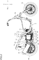
FIG. 1 is a right side view of a scooter according to a preferred embodiment. -
FIG. 2 is a right side view of the scooter when a front cover, a side cover and the like are detached. -
FIG. 3 is a bottom view of the scooter. -
FIG. 4 is a partial plan view of the scooter. -
FIG. 5 is a partial front view of the scooter. -
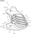
FIG. 6 is a perspective view of a cover. -
FIG. 7 is a partial right side view of the scooter. -
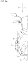
FIG. 8A is a partial front view of the scooter. -
FIG. 8B is a partially cut-out view illustrating the front cover and corresponding toFIG. 8A . -
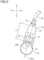
FIG. 9 is a cross-sectional view of a second oxygen sensor and a second exhaust pipe and illustrates a cross section including a central line of the second oxygen sensor and perpendicular to a central line of the second exhaust pipe. -
FIG. 10 is a partial plan view of the scooter and is used for describing flowing air flowing along a sensor cover and a silencer cover. -
FIG. 11 is a view corresponding toFIG. 10 in a case where no sensor cover is assumed to be provided. -
FIG. 12 is a view corresponding toFIG. 10 in a case where a distance between a rear end of the sensor cover and a front end of a front portion of the silencer cover in a vehicle fore-and-aft direction is large. - A preferred embodiment of the present invention will be described hereinafter with reference to the drawings. As illustrated in
FIGS. 1 and2 , a straddled vehicle according to this preferred embodiment is ascooter 1 including anoxygen sensor 50 for detecting an oxygen concentration of an exhaust gas. - The
scooter 1 includes a seat 2 on which a rider is seated. Unless otherwise specified, the terms front, rear, left, right, up, and down as used in the description below, refer to front, rear, left, right, up, and down, respectively, as seen from an imaginary rider sitting on the seat 2 in a case where thescooter 1 on which the rider is not seated and a load is not mounted and which is not filled with fuel is stationary in an upright position on a horizontal surface. The reference characters F, Re, L, R, U, and D in the drawings represent front, rear, left, right, up, and down, respectively. -
FIG. 2 is a side view of thescooter 1 when afront cover 28 and aside cover 29 described later. As illustrated inFIGS. 1 and2 , thescooter 1 includes avehicle body frame 3, afront wheel 35, arear wheel 36, afoot board 4, apivot shaft 6 provided on thevehicle body frame 3. Thefoot board 4 is supported by thevehicle body frame 3, and at least a portion of thefoot board 4 is disposed rearward of thefront wheel 35. Thescooter 1 also includes afront cover 28 at least partially located below ahead pipe 3A of thevehicle body frame 3, theside cover 29 disposed outward of thevehicle body frame 3 in a vehicle width direction, and an undercover 5 disposed below thefront cover 28 and theside cover 29. At least a portion of theunder cover 5 is disposed below thefoot board 4 and behind thefront wheel 35. Theengine unit 10 is swingably supported by thepivot shaft 6, and at least a portion of theengine unit 10 is disposed below thefoot board 4. - As illustrated in
FIG. 2 , theengine unit 10 includes aninternal combustion engine 11A. Theinternal combustion engine 11A includes acrankcase 11, acylinder body 12 connected to thecrankcase 11, and acylinder head 13 connected to thecylinder body 12. Although not shown, a crank shaft of theinternal combustion engine 11A is disposed inside thecrankcase 11. Thecylinder body 12 is disposed ahead of thecrankcase 11, and thecylinder head 13 is disposed ahead of thecylinder body 12. Thecylinder head 13 includes anexhaust port 14 from which an exhaust gas is exhausted. - The
engine unit 10 includes a transmission case 7 (seeFIG. 3 ) disposed at the left of therear wheel 36, and an unillustrated belt continuously variable transmission (hereinafter referred to as a CVT) disposed inside the transmission case 7. The CVT is coupled to the crank shaft of theinternal combustion engine 11A and therear wheel 36, and transfers a torque of the crank shaft to therear wheel 36 so that a transmission gear ratio is changeable. Therear wheel 36 is driven by theinternal combustion engine 11A. As illustrated inFIG. 4 , arear arm 8 coupling thecrankcase 11 and therear wheel 36 to each other is disposed at the right of therear wheel 36. Therear wheel 36 is supported by theengine unit 10 and therear arm 8, and swings together with theengine unit 10 and therear arm 8. Arear cushion unit 9 is disposed between thevehicle body frame 3 and the rear arm 8 (seeFIG. 2 ) . When theengine unit 10 swings upward, therear cushion unit 9 contracts, whereas when theengine unit 10 swings downward, therear cushion unit 9 extends. - In this preferred embodiment, the
internal combustion engine 11A of theengine unit 10 is of a water-cooled type. As illustrated inFIGS. 4 and5 , afan 16 is disposed at the right of thecrankcase 11, and aradiator 15 is disposed at the right of thefan 16. - As illustrated in
FIG. 1 , acover 60 is disposed at the right of theradiator 15.FIG. 6 is a perspective view of thecover 60. Thecover 60 includes afan cover 61, alower extension cover 62 extending rearward from a lower portion of thefan cover 61, and an upper extension cover 63 extending rearward from an upper portion of thefan cover 61, which will be described later in detail. Thecover 60 is a single part, and thefan cover 61, thelower extension cover 62, and the upper extension cover 63 are integrally formed. - The
fan cover 61 is a cover which is located in a region overlapping thefan 16 in a vehicle side view. In other words, thefan cover 61 is a cover which is located just beside thefan 16.FIG. 6 illustrates a contour of thefan 16 by a broken line. In this preferred embodiment, a portion of thecover 60 on the contour and a portion of thecover 60 inside the contour in the vehicle side view correspond to thefan cover 61. Thefan cover 61 has a plurality ofopenings fan cover 61 has five vertically arrangedfront openings 17a and three vertically arrangedrear openings 17b. Theseopenings fan cover 61 are not limited to any of a specific number, a specific shape, and a specific position. - When an impeller (not shown) of the
fan 16 rotates, air is supplied to theradiator 15 through theopenings fan cover 61. Thefan 16, theradiator 15, and thecover 60, which are supported by thecrankcase 11, swing integrally with theengine unit 10. Theinternal combustion engine 11A of theengine unit 10 is not necessarily of a water-cooled type. Theinternal combustion engine 11A may be of an air-cooled type, and theradiator 15 may not be provided. - The
lower extension cover 62 includes anupper edge portion 62a and alower edge portion 62b each extending rearward, and arear edge portion 62c extending from the rear end of theupper edge portion 62a to the rear end of thelower edge portion 62b. Therear edge portion 62c includes an upper portion 62c1 extending forward and downward from the rear end of theupper edge portion 62a and a lower portion 62c2 extending forward and upward from the rear end of thelower edge portion 62b. Therear edge portion 62c is recessed forward. - The
upper extension cover 63 includes anupper edge portion 63a extending rearward and downward and alower edge portion 63b extending rearward and upward. The upper extension cover 63 protrudes rearward. This shape of theupper extension cover 63 is merely an example, and theupper extension cover 63 is not limited to a specific shape. Theupper extension cover 63 is not necessarily provided, and may be omitted. - As illustrated in
FIG. 1 , thescooter 1 includes anexhaust pipe 24 and asilencer 25. Theexhaust pipe 24 includes afirst exhaust pipe 21, acatalyst case 23 accommodating thecatalyst 20, and asecond exhaust pipe 22. Asilencer cover 26 is disposed at a side of thesilencer 25. Thefirst exhaust pipe 21, thecatalyst case 23, thesecond exhaust pipe 22, thesilencer 25, and thesilencer cover 26 are configured to swing integrally with theengine unit 10. - As illustrated in
FIG. 3 , anupstream end portion 21a of thefirst exhaust pipe 21 is connected to theexhaust port 14 of thecylinder head 13. Thefirst exhaust pipe 21 and thecatalyst case 23 are connected to each other by a first pipe fitting 31. Thecatalyst case 23 and thesecond exhaust pipe 22 are connected to each other by a second pipe fitting 32. Thesecond exhaust pipe 22 and thesilencer 25 are connected to each other by a third pipe fitting 33. - The
first exhaust pipe 21 is a metal pipe. Thefirst exhaust pipe 21 is disposed below theengine unit 10. As illustrated inFIG. 3 , in a vehicle bottom view, thefirst exhaust pipe 21 overlaps theengine unit 10. - The
second exhaust pipe 22 is also a metal pipe. Thesecond exhaust pipe 22 extends rearward and outward in the vehicle width direction in the vehicle bottom view. As illustrated inFIG. 1 , in a vehicle side view, thesecond exhaust pipe 22 extends rearward and upward. - The
catalyst case 23 is made of a metal cylinder. Thecatalyst case 23 is not limited to a specific shape. Thecatalyst 20 is disposed inside thecatalyst case 23. Thecatalyst 20 is disposed inside theexhaust pipe 24 and purifies an exhaust gas flowing in theexhaust pipe 24. Thecatalyst case 23 is disposed forward of therear wheel 36, and thecatalyst 20 is disposed forward of therear wheel 36. Thecatalyst case 23 has an inside diameter larger than an inside diameter of each of thefirst exhaust pipe 21 and thesecond exhaust pipe 22. Thecatalyst case 23 has an outside diameter larger than an outside diameter of each of thefirst exhaust pipe 21 and thesecond exhaust pipe 22. As illustrated inFIG. 3 , in the vehicle bottom view, thecatalyst case 23 extends rearward and outward in the vehicle width direction. As illustrated inFIG. 1 , in the vehicle side view, thecatalyst case 23 extends rearward. Thecatalyst case 23 is not limited to a specific posture in placing. - As illustrated in
FIG. 7 , afirst oxygen sensor 40 is attached to thefirst exhaust pipe 21. Thefirst oxygen sensor 40 is disposed upstream of thecatalyst 20 and detects an oxygen concentration of an exhaust gas before purification by thecatalyst 20. Based on the oxygen concentration of the exhaust gas detected by thefirst oxygen sensor 40, an air-fuel ratio of an exhaust gas emitted from theinternal combustion engine 11A can be detected. Thus, based on a detection result of thefirst oxygen sensor 40, theinternal combustion engine 11A can be controlled to obtain a predetermined combustion state. - As illustrated in
FIG. 3 , thefirst oxygen sensor 40 is attached to a portion of thefirst exhaust pipe 21 closer to thecatalyst 20 than an intermediate position (position indicated by a broken line inFIG. 3 ) 21m of thefirst exhaust pipe 21. The intermediate position of thefirst exhaust pipe 21 is an intermediate position between theupstream end portion 21a and thedownstream end portion 21b in a direction along the central line of thefirst exhaust pipe 21. Thefirst oxygen sensor 40 is disposed rearward of thecylinder body 12 of theengine unit 10. Thefirst oxygen sensor 40 is disposed rearward of thepivot shaft 6 swingably supporting theengine unit 10. - As illustrated in
FIG. 7 , thefirst exhaust pipe 21 includes anattachment portion 43 for attaching thefirst oxygen sensor 40. Theattachment portion 43 is cylindrical, and is welded to thefirst exhaust pipe 21. - As illustrated in
FIG. 1 , in the vehicle side view, thefirst oxygen sensor 40 is not covered with theside cover 29 and is exposed. Thefirst oxygen sensor 40 is disposed to be visually recognized when thescooter 1 is seen from the right. As illustrated inFIG. 3 , in the vehicle bottom view, thefirst oxygen sensor 40 overlaps thecrankcase 11 but does not overlap the undercover 5. In the vehicle bottom view, at least a portion of thefirst oxygen sensor 40 is disposed at the right of aleft end 35L of thefront wheel 35 and at the left of aright end 35R of thefront wheel 35. Thefirst oxygen sensor 40 is disposed near the center of the vehicle. - As illustrated in
FIG. 7 , asecond oxygen sensor 50 is attached to thesecond exhaust pipe 22. Thesecond oxygen sensor 50 is disposed downstream of thecatalyst 20 and detects the oxygen concentration of an exhaust gas purified by thecatalyst 20. If thecatalyst 20 has deteriorated, the exhaust gas is not appropriately purified. Thus, based on a detection result of thesecond oxygen sensor 50, it can be detected whether thecatalyst 20 has deteriorated or not. Deterioration of thecatalyst 20 may be detected by comparing the detection result of thefirst oxygen sensor 40 and the detection result of thesecond oxygen sensor 50. - As illustrated in
FIG. 7 , thesecond exhaust pipe 22 includes anattachment portion 54 for attaching thesecond oxygen sensor 50. Theattachment portion 54 is cylindrical, and is welded to thesecond exhaust pipe 22. - As illustrated in
FIG. 2 , thesecond oxygen sensor 50 is disposed rearward of theinternal combustion engine 11A of theengine unit 10. As illustrated inFIG. 7 , at least a portion of thesecond oxygen sensor 50 overlaps therear wheel 36 in a vehicle side view. - As illustrated in
FIG. 9 , thesecond oxygen sensor 50 includes asensor element 51 located inside thesecond exhaust pipe 22, acylindrical case 52 located outside thesecond exhaust pipe 22, and aheater 53 for heating thesensor element 51. Thesensor element 51 includes a material such as zirconia. Theheater 53 is incorporated in thesecond oxygen sensor 50. - As illustrated in
FIG. 9 , in a cross section including acentral line 50C of thesecond oxygen sensor 50 and perpendicular to thecentral line 22C of thesecond exhaust pipe 22, at least a portion of thecase 52 is located inward of thecentral line 22C of thesecond exhaust pipe 22 in the vehicle width direction and above thecentral line 22C. The posture of thesecond oxygen sensor 50 in placing described here is an example, and the posture of thesecond oxygen sensor 50 in placing is not limited to a specific posture. The expression of inward in the vehicle width direction refers to the direction toward a vehicle central line CL, and the expression of outward in the vehicle width direction refers to the direction away from the vehicle central line CL (seeFIG. 3 ). - As illustrated in
FIG. 1 , afirst wire 45 is connected to thefirst oxygen sensor 40. A portion of thefirst wire 45 is exposed in the vehicle side view. The portion of thefirst wire 45 is visually recognized when seen from the right. Accordingly, thefirst wire 45 can be easily handled from the right in maintenance or the like of thefirst oxygen sensor 40, and thus, maintenance of thefirst oxygen sensor 40 can be easily performed. Thefirst wire 45 extends upward from thefirst oxygen sensor 40 and then extends forward. Thefirst wire 45 does not pass under theengine unit 10. Thefirst wire 45 is connected to an unillustrated electronic control unit (ECU). - As illustrated in
FIG. 9 , thesecond oxygen sensor 50 includes awire connection portion 55, and asecond wire 46 is connected to thewire connection portion 55. Thewire connection portion 55 is disposed above thesensor element 51 in a vehicle vertical direction, and inward of thesensor element 51 in the vehicle width direction. As illustrated inFIG. 7 , thesecond wire 46 extends upward from thesecond oxygen sensor 50 and then extends forward. Thesecond wire 46 passes above thefan 16. Aportion 46a of thesecond wire 46 is disposed above thefan 16. Thesecond wire 46 does not pass under theengine unit 10. Thesecond wire 46 is connected to the ECU. - As illustrated in
FIGS. 8A and8B , thefirst oxygen sensor 40 and thesecond oxygen sensor 50 overlap the undercover 5 in a vehicle front view. Thefirst oxygen sensor 40 and thesecond oxygen sensor 50 are disposed not to be visually recognized when thescooter 1 is seen from the front. - As illustrated in
FIG. 7 , a portion of thelower extension cover 62 overlaps at least a portion of thesecond oxygen sensor 50 in a vehicle side view. In this preferred embodiment, the portion of thelower extension cover 62 constitutes asensor cover 65. Thesensor cover 65 is disposed rearward of theopenings fan cover 61. As illustrated inFIG. 4 , thesensor cover 65 is located outward of thesecond oxygen sensor 50 in the vehicle width direction. Thelower extension cover 62 extends outward in the vehicle width direction and rearward in the vehicle fore-and-aft direction. Thesensor cover 65 also extends outward in the vehicle width direction and rearward in the vehicle fore-and-aft direction. - The
silencer cover 26 is disposed outward of thesilencer 25 in the vehicle width direction. Afront portion 26a of thesilencer cover 26 is located outward of thesecond oxygen sensor 50 in the vehicle width direction. Thefront portion 26a of thesilencer cover 26 extends outward in the vehicle width direction and rearward in the vehicle fore-and-aft direction, and in this preferred embodiment, is curved. - In this preferred embodiment, as illustrated in
FIG. 4 , arear end 62d of thelower extension cover 62 and a front end 26aa of thefront portion 26a of thesilencer cover 26 are at the same position in the vehicle fore-and-aft direction in a vehicle plan view. In the vehicle plan view, suppose a straight line passing through therear end 62d of thelower extension cover 62 and extending in the vehicle width direction is L1, and a straight line passing through the front end 26aa of thefront portion 26a of thesilencer cover 26 and extending in the vehicle width direction is L2, the line L1 and the line L2 coincide with each other. Suppose a distance between therear end 62d of thelower extension cover 62 and the front end 26aa of thefront portion 26a of thesilencer cover 26 in the vehicle fore-and-aft direction is ΔA, ΔA = 0 is established in this preferred embodiment. InFIG. 7 ,character 61a denotes a rear end of thefan cover 61. InFIG. 4 , character L3 denotes a straight line passing through therear end 61a of thefan cover 61 and extending in the vehicle width direction in the vehicle plan view. Character L4 denotes a straight line passing through afront end 25a of thesilencer 25 and extending in the vehicle width direction in the vehicle plan view. In the vehicle plan view, a distance between therear end 61a of thefan cover 61 and thefront end 25a of thesilencer 25 in the vehicle fore-and-aft direction is defined as ΔB. Then, ΔA < ΔB is established. - In
FIG. 4 , character L5 denotes a straight line passing through an inner end 26ae in the vehicle width direction of thefront portion 26a of thesilencer cover 26 and extending in the vehicle fore-and-aft direction in the vehicle plan view. Character L6 denotes a straight line passing through anouter end 62e in the vehicle width direction of thelower extension cover 62 and extending in the vehicle fore-and-aft direction in the vehicle plan view. In this example, the line L5 is located inward of the line L6 in the vehicle width direction. That is, in the vehicle plan view, the inner end 26ae in the vehicle width direction of thefront portion 26a of thesilencer cover 26 is located inward of theouter end 62e in the vehicle width direction of thelower extension cover 62 in the vehicle width direction. - In this preferred embodiment, as described above, the front end 26aa of the
front portion 26a of thesilencer cover 26 is at a position identical to therear end 62d of thelower extension cover 62 in the vehicle fore-and-aft direction, but this positional relationship is not specifically limited. In the vehicle fore-and-aft direction, the front end 26aa of thefront portion 26a of thesilencer cover 26 may be located forward of therear end 62d of thelower extension cover 62, and ΔA > 0 may be established. Even in the case of ΔA > 0, the relationship of ΔA < ΔB is preferable. - As illustrated in
FIG. 7 , thesensor cover 65 and thefront portion 26a of thesilencer cover 26 are formed in shapes that match each other in the vehicle side view. In this example, in the vehicle side view, thesensor cover 65 has arecess 65a that is recessed forward, and thefront portion 26a of thesilencer cover 26 has a projection 26ab projecting forward toward therecess 65a. - In the vehicle side view, a gap is provided between the
sensor cover 65 and thefront portion 26a of thesilencer cover 26 in the vehicle fore-and-aft direction, but the gap is relatively small. The gap varies depending on the vertical position, and a minimum gap G1 is smaller than an axial dimension F1 (seeFIG. 9 ) of thecase 52 of thesecond oxygen sensor 50. However, this is only an example, and the minimum gap G1 is not specifically limited. - The
sensor cover 65 overlaps thewire connection portion 55 of thesecond oxygen sensor 50 in a vehicle side view. A portion of thesecond wire 46 overlaps thesensor cover 65 in the vehicle side view. Another portion of thesecond wire 46 is located inward of the upper extension cover 63 of thecover 60 in the vehicle width direction, and overlaps the upper extension cover 63 in the vehicle side view. A portion of theupper extension cover 63 constitutes thewire cover 66. Theportion 46a of thesecond wire 46 is located above thefan 16 and inward of thefan cover 61 in the vehicle width direction, and extends forward. - The configuration of the
scooter 1 has been described above. Next, the influence of flowing air on thesecond oxygen sensor 50 will be described. - When the
scooter 1 travels, air (i.e., flowing air) W flows from the front toward the rear, as illustrated inFIG. 10 . Thefan cover 61 is disposed at a position at which the flowing air W hits thefan cover 61 such that air can be easily introduced into theopenings FIG. 6 ). In this preferred embodiment, thesecond oxygen sensor 50 is disposed near thefan cover 61. Here, suppose nosensor cover 65 is provided as illustrated inFIG. 11 , flowing air W1 that has flowed along thefan cover 61 flows toward thesecond oxygen sensor 50 to cool thesecond oxygen sensor 50. In this case, although thesecond oxygen sensor 50 incorporates the heater 53 (seeFIG. 9 ), the temperature of thesensor element 51 decreases so that a detection accuracy might decrease. - On the other hand, in this preferred embodiment, the
sensor cover 65 integrally formed with thefan cover 61 is disposed outward of thesecond oxygen sensor 50 in the vehicle width direction. This prevents flowing air W1 from directly blowing thesecond oxygen sensor 50. On the other hand, as illustrated inFIG. 12 , in a case where a distance ΔA between arear end 65d of thesensor cover 65 and the front end 26aa of thefront portion 26a of thesilencer cover 26 in the vehicle fore-and-aft direction is large, a negative pressure is generated behind thesensor cover 65, and accordingly, flowing air W2 that has flowed along the surface of thesensor cover 65 flows into the inside of thesensor cover 65 to flow around thesecond oxygen sensor 50. - On the other hand, in this preferred embodiment, the distance ΔA between the
rear end 65d of thesensor cover 65 and the front end 26aa of thefront portion 26a of thesilencer cover 26 in the vehicle fore-and-aft direction is small and zero (seeFIG. 4 ) . In addition, thesensor cover 65 and thefront portion 26a of thesilencer cover 26 both extend outward in the vehicle width direction and rearward in the vehicle fore-and-aft direction. Thus, as illustrated inFIG. 10 , flowing air W3 that has flowed along the surface of thesensor cover 65 tends to flow rearward along the surface of thefront portion 26a of thesilencer cover 26. In the manner described above, in this preferred embodiment, thesensor cover 65 and thesilencer cover 26 cooperate to thereby suppress a flow of flowing air toward thesecond oxygen sensor 50. - As described above, in the
scooter 1 according to this preferred embodiment, a flow of flowing air toward thesecond oxygen sensor 50 is suppressed so that cooling of thesecond oxygen sensor 50 by flowing air is suppressed. Accordingly, temperature of thesensor element 51 is suppressed to decrease so that accuracy of thesecond oxygen sensor 50 can be kept sufficiently high. - The
sensor cover 65 and thefront portion 26a of thesilencer cover 26 are not limited to a specific positional relationship. In this embodiment, as illustrated inFIG. 4 , the inner end 26ae in the vehicle width direction of thefront portion 26a of thesilencer cover 26 is located inward of theouter end 62e in the vehicle width direction of thesensor cover 65 in the vehicle width direction in the vehicle plan view. In this preferred embodiment, in the vehicle plan view, the front end 26aa of thefront portion 26a of thesilencer cover 26 is located inward of theouter end 62e in the vehicle width direction of thesensor cover 65 in the vehicle width direction. In this preferred embodiment, since thesensor cover 65 and thefront portion 26a of thesilencer cover 26 have the positional relationship described above, it is possible to further suppress a flow of flowing air toward the surroundings of thesecond oxygen sensor 50 by a negative pressure. - In this preferred embodiment, in the vehicle fore-and-aft direction, the front end 26aa of the
front portion 26a of thesilencer cover 26 is located at a position identical to therear end 62d of thesensor cover 65. That is, ΔA = 0 is established. Accordingly, it is possible to further suppress a flow of flowing air to the surroundings of thesecond oxygen sensor 50 by a negative pressure. - If the
second oxygen sensor 50 is disposed near theexhaust port 14 of theinternal combustion engine 11A of theengine unit 10, thesecond oxygen sensor 50 is heated by a high-temperature exhaust gas immediately after being emitted from theexhaust port 14. In this case, the temperature of thesensor element 51 of thesecond oxygen sensor 50 does not readily decrease. On the other hand, in this preferred embodiment, as illustrated inFIG. 2 , thesecond oxygen sensor 50 is disposed rearward of theinternal combustion engine 11A of theengine unit 10. In addition, thesecond oxygen sensor 50 is disposed rearward such that at least a portion of thesecond oxygen sensor 50 overlaps therear wheel 36 in the vehicle side view. Thesecond oxygen sensor 50 is disposed downstream of thecatalyst 20 in a flow direction of an exhaust gas. In this preferred embodiment, thesecond oxygen sensor 50 is disposed away from theexhaust port 14, and is located near thefan cover 61. Thus, the advantage of keeping a sufficiently high accuracy of thesecond oxygen sensor 50 by suppressing a temperature decrease in thesensor element 51 become more significant. - In this preferred embodiment, as illustrated in
FIG. 7 , thesensor cover 65 is disposed rearward of theopenings fan cover 61. Accordingly, a portion of flowing air can be supplied to thefan 16 through theopenings sensor cover 65 can smoothly guide another portion of the flowing air rearward while preventing the flowing air from blowing thesecond oxygen sensor 50. - In this preferred embodiment, in the vehicle side view, the minimum gap G1 between the
sensor cover 65 and thefront portion 26a of thesilencer cover 26 in the vehicle fore-and-aft direction is smaller than the axial dimension F1 (seeFIG. 9 ) of thecase 52 of thesecond oxygen sensor 50. Since the minimum gap G1 between thesensor cover 65 and thefront portion 26a of thesilencer cover 26 in the vehicle fore-and-aft direction is small as described above, it is possible to further reduce a flow of flowing air to the surroundings of thesecond oxygen sensor 50 by a negative pressure. - In this preferred embodiment, in the vehicle side view, the
sensor cover 65 has therecess 65a that is recessed forward, and thefront portion 26a of thesilencer cover 26 has the projection 26ab that projects forward toward therecess 65a. Thesensor cover 65 and thefront portion 26a of thesilencer cover 26 are formed in shapes that match each other in the vehicle side view. Accordingly, it is possible to effectively suppress a flow of flowing air that has flowed along the surface of thesensor cover 65, and cooling of thesecond oxygen sensor 50 by flowing air can be effectively suppressed. - In this preferred embodiment, the
sensor cover 65 overlaps thewire connection portion 55 of thesecond oxygen sensor 50 in the vehicle side view. Thus, thesensor cover 65 protects thewire connection portion 55 of thesecond oxygen sensor 50. - In this preferred embodiment, the
cover 60 includes thewire cover 66 that is located outward of at least a portion of thesecond wire 46 in the vehicle width direction and overlaps at least a portion of thesecond wire 46 in the vehicle side view. Accordingly, thewire cover 66 protects at least a portion of thesecond wire 46. - In this preferred embodiment, as illustrated in
FIG. 9 , thewire connection portion 55 of thesecond oxygen sensor 50 is disposed above thesensor element 51 in the vehicle vertical direction and inward of thesensor element 51 in the vehicle width direction. Since thewire connection portion 55 is located above thesensor element 51 as described above, maintenance of thesecond oxygen sensor 50 can be easily performed. In addition, since thewire connection portion 55 is located inward of thesensor element 51 in the vehicle width direction, extension of thewire connection portion 55 outward in the vehicle width direction is avoided. - In this preferred embodiment, as illustrated in
FIG. 7 , thesecond wire 46 has aportion 46a disposed above thefan 16 and inward of thefan cover 61 in the vehicle width direction and extending forward. Accordingly, thesecond wire 46 is easily routed. - Although one preferred embodiment of the present invention has been described above, the present invention is, of course, not limited to this preferred embodiment.
- In the preferred embodiment, the transmission case 7 of the
engine unit 10 is disposed at the left of the vehicle central line CL, and thesecond oxygen sensor 50, thecover 60, and thesilencer cover 26 are located at the right of the vehicle central line CL. Alternatively, the transmission case 7 may be disposed at the right of the vehicle central line CL with thesecond oxygen sensor 50, thecover 60, and thesilencer cover 26 being disposed at the left of the vehicle central line CL. - In the preferred embodiment, at least a portion of the
second oxygen sensor 50 overlaps therear wheel 36 in the vehicle side view. Alternatively, the entiresecond oxygen sensor 50 may not overlap therear wheel 36 in the vehicle side view. - In the preferred embodiment, the
second oxygen sensor 50 is disposed downstream of thecatalyst 20. However, the location of thesecond oxygen sensor 50 is not limited to a specific location. Thesecond oxygen sensor 50 may be disposed upstream of thecatalyst 20. - In the preferred embodiment, the
sensor cover 65 is disposed rearward of theopenings fan cover 61. A portion of thesensor cover 65 orwhole sensor cover 65 may not be disposed rearward of theopenings fan cover 61. - In the preferred embodiment, the
sensor cover 65 has therecess 65a, thefront portion 26a of thesilencer cover 26 has the projection 26ab, and thesensor cover 65 and thefront portion 26a of thesilencer cover 26 have shapes that match each other in the vehicle side view. Alternatively, thesensor cover 65 and thefront portion 26a of thesilencer cover 26 may have shapes that do not match each other in the vehicle side view. - In the preferred embodiment, the
sensor cover 65 overlaps thewire connection portion 55 of thesecond oxygen sensor 50 in the vehicle side view, but is not limited to a specific positional relationship. Thesensor cover 65 may not overlap a portion of thesecond oxygen sensor 50 in the vehicle side view or wholesecond oxygen sensor 50 in the vehicle side view. - In the preferred embodiment, the
cover 60 includes thewire cover 66 that overlaps at least a portion of thesecond wire 46 in the vehicle side view. Alternatively, thecover 60 may not include such awire cover 66. - The posture of the
second oxygen sensor 50 in placing is not specifically limited. Thewire connection portion 55 may be disposed below thesensor element 51 in the vehicle vertical direction. Thewire connection portion 55 may be disposed outward of thesensor element 51 in the vehicle width direction. - In the preferred embodiment, the
internal combustion engine 11A of theengine unit 10 is of a water-cooled type, and thescooter 1 includes theradiator 15. Alternatively, theinternal combustion engine 11A may be of an air-cooled type. Thescooter 1 may not include theradiator 15. Thefan 16 may be configured to supply air to theinternal combustion engine 11A. - A straddled vehicle as used herein refers to a vehicle on which a rider sits astride. The straddled vehicle is not limited to the
scooter 1. The straddled vehicle may be a motorcycle of another type. The straddled vehicle may be a vehicle other than a motorcycle, such as a motor tricycle or an all terrain vehicle (ATV) . - 1 scooter (straddled vehicle), 10 engine unit, 15 radiator, 16 fan, 17a opening, 17b opening, 20 catalyst, 24 exhaust pipe, 25 silencer, 26 silencer cover, 26a front portion of silencer cover, 35 front wheel, 36 rear wheel, 46 second wire (wire), 46a wire portion, 50 second oxygen sensor (oxygen sensor), 51 sensor element, 52 case, 53 heater, 55 wire connection portion, 60 cover, 61 fan cover, 65 sensor cover, 66 wire cover
Claims (16)
- A straddled vehicle (1) comprising:an internal combustion engine (11A);an exhaust pipe (24) connected to the internal combustion engine (11A);a silencer (25) disposed rearward of the exhaust pipe (24) and connected to the exhaust pipe (24);a fan (16) disposed outward of the internal combustion engine (11A) in a vehicle width direction;a fan cover (61) disposed outward of the fan (16) in the vehicle width direction and having an opening (17a, 17b);a silencer cover (26) disposed outward of the silencer (25) in the vehicle width direction;an oxygen sensor (50) including a sensor element (51) disposed inside the exhaust pipe (24) and a heater (53) that heats the sensor element (51), the oxygen sensor (50) being attached to the exhaust pipe (24); anda sensor cover (65) integrally formed with the fan cover (61), located outward of the oxygen sensor (50) in the vehicle width direction, overlapping at least a portion of the oxygen sensor (50) in a vehicle side view, and extending outward in the vehicle width direction and rearward in a vehicle fore-and-aft direction, whereinthe silencer cover (26) has a front portion (26a) located outward of the oxygen sensor (50) in the vehicle width direction and extending outward in the vehicle width direction and rearward in the vehicle fore-and-aft direction, andin a vehicle plan view, a distance (ΔA) between a rear end (62d) of the sensor cover (65) and a front end (26aa) of the front portion (26a) of the silencer cover (26) in the vehicle fore-and-aft direction is smaller than a distance (ΔB) between a rear end (61a) of the fan cover (61) and a front end (25a) of the silencer (25) .
- The straddled vehicle (1) according to claim 1, wherein in the vehicle plan view, an inner end (26ae) in the vehicle width direction of the front portion (26a) of the silencer cover (26) is located inward of an outer end (62e) in the vehicle width direction of the sensor cover (65) in the vehicle width direction.
- The straddled vehicle (1) according to claim 1 or 2, wherein in the vehicle plan view, a front end (26aa) of the front portion (26a) of the silencer cover (26) is located inward of the outer end (62e) in the vehicle width direction of the sensor cover (65) in the vehicle width direction.
- The straddled vehicle (1) according claim 3, wherein in a vehicle fore-and-aft direction, the front end (26aa) of the front portion (26a) of the silencer cover (26) is located at a position identical to a rear end (62d) of the sensor cover (65) or forward of the rear end (62d) of the sensor cover (65).
- The straddled vehicle (1) according to any one of claims 1 to 4, wherein the oxygen sensor (50) is located rearward of the internal combustion engine (11A).
- The straddled vehicle (1) according to any one of claims 1 to 5, comprising a rear wheel (36) that is driven by the internal combustion engine (11A), wherein
at least a portion of the oxygen sensor (50) overlaps the rear wheel (36) in a vehicle side view. - The straddled vehicle (1) according to any one of claims 1 to 6, comprising a catalyst (20) that purifies an exhaust gas flowing in the exhaust pipe (24), wherein
the oxygen sensor (50) is disposed downstream of the catalyst (20) in a flow direction of the exhaust gas. - The straddled vehicle (1) according to any one of claims 1 to 7, wherein the sensor cover (65) is disposed rearward of the opening (17a, 17b) of the fan cover (61).
- The straddled vehicle (1) according to any one of claims 1 to 8, wherein
the oxygen sensor (50) includes a cylindrical case (52) located outside the exhaust pipe (24), and
in a vehicle side view, a minimum gap (G1) between the sensor cover (65) and the front portion (26a) of the silencer cover (26) in a vehicle fore-and-aft direction is smaller than an axial dimension (F1) of the case (52) of the oxygen sensor (50). - The straddled vehicle (1) according to any one of claims 1 to 9, wherein in a vehicle side view, the sensor cover (65) has a recess (65a) that is recessed forward, and the front portion (26a) of the silencer cover (26) has a projection (26ab) projecting forward toward the recess (65a).
- The straddled vehicle (1) according to any one of claims 1 to 10, wherein
the oxygen sensor (50) includes a wire connection portion (55), and
the straddled vehicle (1) includes a wire (46) connected to the wire connection portion (55). - The straddled vehicle (1) according to claim 11, wherein the sensor cover (65) overlaps the wire connection portion (55) of the oxygen sensor (50) in a vehicle side view.
- The straddled vehicle (1) according to claim 11 or 12, comprising a wire cover (66) integrally formed with the fan cover (61), located outward of at least a portion of the wire (46) in the vehicle width direction, and overlapping at least a portion of the wire (46) in a vehicle side view.
- The straddled vehicle (1) according to any one of claims 11 to 13, wherein
the oxygen sensor (50) includes a sensor element (51) located inside the exhaust pipe (24), and
the wire connection portion (55) is disposed above the sensor element (51) in a vehicle vertical direction and inward of the sensor element (51) in the vehicle width direction. - The straddled vehicle (1) according to any one of claims 11 to 14, wherein the wire (46) includes a wire portion (46a) disposed above the fan (16) and inward of the fan cover (61) in the vehicle width direction and extending forward.
- The straddled vehicle (1) according to any one of claims 1 to 15, comprising a radiator (15) disposed between the fan cover (61) and the fan (16).
Applications Claiming Priority (1)
| Application Number | Priority Date | Filing Date | Title |
|---|---|---|---|
| JP2018083218A JP2019190355A (en) | 2018-04-24 | 2018-04-24 | Saddle riding-type vehicle |
Publications (2)
| Publication Number | Publication Date |
|---|---|
| EP3561246A1 true EP3561246A1 (en) | 2019-10-30 |
| EP3561246B1 EP3561246B1 (en) | 2020-12-02 |
Family
ID=66104996
Family Applications (1)
| Application Number | Title | Priority Date | Filing Date |
|---|---|---|---|
| EP19168292.1A Active EP3561246B1 (en) | 2018-04-24 | 2019-04-10 | Straddled vehicle |
Country Status (4)
| Country | Link |
|---|---|
| EP (1) | EP3561246B1 (en) |
| JP (1) | JP2019190355A (en) |
| PH (1) | PH12019050057A1 (en) |
| TW (1) | TWI727290B (en) |
Families Citing this family (2)
| Publication number | Priority date | Publication date | Assignee | Title |
|---|---|---|---|---|
| TWI758076B (en) * | 2021-01-20 | 2022-03-11 | 光陽工業股份有限公司 | Cooling mechanism of continuously variable transmission system |
| JP7649354B1 (en) | 2023-09-29 | 2025-03-19 | 本田技研工業株式会社 | Exhaust system |
Citations (4)
| Publication number | Priority date | Publication date | Assignee | Title |
|---|---|---|---|---|
| JP2009226988A (en) | 2008-03-19 | 2009-10-08 | Suzuki Motor Corp | Exhaust gas sensor apparatus of motorcycle |
| US20130220724A1 (en) * | 2012-02-27 | 2013-08-29 | Honda Motor Co., Ltd. | Body cover system for a small vehicle, and vehicle including same |
| EP3165730A1 (en) * | 2014-07-04 | 2017-05-10 | Yamaha Hatsudoki Kabushiki Kaisha | Vehicle and single-cylinder four-stroke engine unit |
| EP3165738A1 (en) * | 2014-07-04 | 2017-05-10 | Yamaha Hatsudoki Kabushiki Kaisha | Saddle-driven vehicle and single-cylinder 4-stroke engine unit |
Family Cites Families (4)
| Publication number | Priority date | Publication date | Assignee | Title |
|---|---|---|---|---|
| JP2017150312A (en) * | 2014-07-04 | 2017-08-31 | ヤマハ発動機株式会社 | Engine units and vehicles |
| EP3165742B1 (en) * | 2014-07-04 | 2021-05-26 | Yamaha Hatsudoki Kabushiki Kaisha | Vehicle and single-cylinder four-stroke engine unit |
| JPWO2016002956A1 (en) * | 2014-07-04 | 2017-04-27 | ヤマハ発動機株式会社 | Vehicle and V-type multi-cylinder 4-stroke engine unit |
| WO2016098900A1 (en) * | 2014-12-19 | 2016-06-23 | ヤマハ発動機株式会社 | Saddle-ride vehicle |
-
2018
- 2018-04-24 JP JP2018083218A patent/JP2019190355A/en active Pending
-
2019
- 2019-03-26 TW TW108110470A patent/TWI727290B/en active
- 2019-04-10 EP EP19168292.1A patent/EP3561246B1/en active Active
- 2019-04-16 PH PH12019050057A patent/PH12019050057A1/en unknown
Patent Citations (4)
| Publication number | Priority date | Publication date | Assignee | Title |
|---|---|---|---|---|
| JP2009226988A (en) | 2008-03-19 | 2009-10-08 | Suzuki Motor Corp | Exhaust gas sensor apparatus of motorcycle |
| US20130220724A1 (en) * | 2012-02-27 | 2013-08-29 | Honda Motor Co., Ltd. | Body cover system for a small vehicle, and vehicle including same |
| EP3165730A1 (en) * | 2014-07-04 | 2017-05-10 | Yamaha Hatsudoki Kabushiki Kaisha | Vehicle and single-cylinder four-stroke engine unit |
| EP3165738A1 (en) * | 2014-07-04 | 2017-05-10 | Yamaha Hatsudoki Kabushiki Kaisha | Saddle-driven vehicle and single-cylinder 4-stroke engine unit |
Also Published As
| Publication number | Publication date |
|---|---|
| TWI727290B (en) | 2021-05-11 |
| TW201945218A (en) | 2019-12-01 |
| EP3561246B1 (en) | 2020-12-02 |
| JP2019190355A (en) | 2019-10-31 |
| PH12019050057A1 (en) | 2019-12-11 |
Similar Documents
| Publication | Publication Date | Title |
|---|---|---|
| EP3235714B1 (en) | Saddle-ride vehicle | |
| EP1905981B1 (en) | Internal Combustion Engine with Wind Exhaust Duct and Vehicle Mounted with Internal Combustion Engine | |
| US8783024B2 (en) | Exhaust chamber in motorcycle exhaust system | |
| JP2007145130A (en) | Motorcycle | |
| US20190063301A1 (en) | Straddle Vehicle and Radiator Air-Guide Device | |
| JP2011064193A (en) | Engine and saddle type vehicle equipped therewith | |
| EP3450293B1 (en) | Saddle riding vehicle | |
| EP3561246B1 (en) | Straddled vehicle | |
| EP3165437B1 (en) | Straddled vehicle | |
| EP3561252B1 (en) | Scooter | |
| BR112021016709A2 (en) | UNLOAD SYSTEM AND ENGINE VEHICLE OF THE SAME | |
| US10920639B2 (en) | Saddle riding vehicle | |
| CN109563780B (en) | straddle vehicle | |
| EP3301273B1 (en) | Saddle type vehicle having water cooled engine | |
| EP2436895B1 (en) | Exhaust apparatus for motorcycle | |
| EP2599991B1 (en) | Saddle riding type vehicle | |
| JP6662732B2 (en) | Saddle-type vehicle | |
| EP3561245B1 (en) | Straddled vehicle | |
| JP6269081B2 (en) | Injector mounting structure | |
| US20250052186A1 (en) | Installation structure of water temperature sensor | |
| US20260062089A1 (en) | Engine | |
| US12359604B2 (en) | Engine | |
| JP2020169589A (en) | Motorcycle | |
| JP4567557B2 (en) | Motorcycle | |
| JP2006007809A (en) | Vehicle air cooling device |
Legal Events
| Date | Code | Title | Description |
|---|---|---|---|
| PUAI | Public reference made under article 153(3) epc to a published international application that has entered the european phase |
Free format text: ORIGINAL CODE: 0009012 |
|
| STAA | Information on the status of an ep patent application or granted ep patent |
Free format text: STATUS: THE APPLICATION HAS BEEN PUBLISHED |
|
| AK | Designated contracting states |
Kind code of ref document: A1 Designated state(s): AL AT BE BG CH CY CZ DE DK EE ES FI FR GB GR HR HU IE IS IT LI LT LU LV MC MK MT NL NO PL PT RO RS SE SI SK SM TR |
|
| AX | Request for extension of the european patent |
Extension state: BA ME |
|
| STAA | Information on the status of an ep patent application or granted ep patent |
Free format text: STATUS: REQUEST FOR EXAMINATION WAS MADE |
|
| 17P | Request for examination filed |
Effective date: 20191203 |
|
| RBV | Designated contracting states (corrected) |
Designated state(s): AL AT BE BG CH CY CZ DE DK EE ES FI FR GB GR HR HU IE IS IT LI LT LU LV MC MK MT NL NO PL PT RO RS SE SI SK SM TR |
|
| GRAP | Despatch of communication of intention to grant a patent |
Free format text: ORIGINAL CODE: EPIDOSNIGR1 |
|
| STAA | Information on the status of an ep patent application or granted ep patent |
Free format text: STATUS: GRANT OF PATENT IS INTENDED |
|
| INTG | Intention to grant announced |
Effective date: 20200714 |
|
| GRAS | Grant fee paid |
Free format text: ORIGINAL CODE: EPIDOSNIGR3 |
|
| GRAA | (expected) grant |
Free format text: ORIGINAL CODE: 0009210 |
|
| STAA | Information on the status of an ep patent application or granted ep patent |
Free format text: STATUS: THE PATENT HAS BEEN GRANTED |
|
| AK | Designated contracting states |
Kind code of ref document: B1 Designated state(s): AL AT BE BG CH CY CZ DE DK EE ES FI FR GB GR HR HU IE IS IT LI LT LU LV MC MK MT NL NO PL PT RO RS SE SI SK SM TR |
|
| REG | Reference to a national code |
Ref country code: GB Ref legal event code: FG4D |
|
| REG | Reference to a national code |
Ref country code: CH Ref legal event code: EP Ref country code: AT Ref legal event code: REF Ref document number: 1341163 Country of ref document: AT Kind code of ref document: T Effective date: 20201215 |
|
| REG | Reference to a national code |
Ref country code: DE Ref legal event code: R096 Ref document number: 602019001543 Country of ref document: DE |
|
| REG | Reference to a national code |
Ref country code: IE Ref legal event code: FG4D |
|
| PG25 | Lapsed in a contracting state [announced via postgrant information from national office to epo] |
Ref country code: NO Free format text: LAPSE BECAUSE OF FAILURE TO SUBMIT A TRANSLATION OF THE DESCRIPTION OR TO PAY THE FEE WITHIN THE PRESCRIBED TIME-LIMIT Effective date: 20210302 Ref country code: GR Free format text: LAPSE BECAUSE OF FAILURE TO SUBMIT A TRANSLATION OF THE DESCRIPTION OR TO PAY THE FEE WITHIN THE PRESCRIBED TIME-LIMIT Effective date: 20210303 Ref country code: FI Free format text: LAPSE BECAUSE OF FAILURE TO SUBMIT A TRANSLATION OF THE DESCRIPTION OR TO PAY THE FEE WITHIN THE PRESCRIBED TIME-LIMIT Effective date: 20201202 Ref country code: RS Free format text: LAPSE BECAUSE OF FAILURE TO SUBMIT A TRANSLATION OF THE DESCRIPTION OR TO PAY THE FEE WITHIN THE PRESCRIBED TIME-LIMIT Effective date: 20201202 |
|
| REG | Reference to a national code |
Ref country code: NL Ref legal event code: MP Effective date: 20201202 |
|
| REG | Reference to a national code |
Ref country code: AT Ref legal event code: MK05 Ref document number: 1341163 Country of ref document: AT Kind code of ref document: T Effective date: 20201202 |
|
| PG25 | Lapsed in a contracting state [announced via postgrant information from national office to epo] |
Ref country code: SE Free format text: LAPSE BECAUSE OF FAILURE TO SUBMIT A TRANSLATION OF THE DESCRIPTION OR TO PAY THE FEE WITHIN THE PRESCRIBED TIME-LIMIT Effective date: 20201202 Ref country code: LV Free format text: LAPSE BECAUSE OF FAILURE TO SUBMIT A TRANSLATION OF THE DESCRIPTION OR TO PAY THE FEE WITHIN THE PRESCRIBED TIME-LIMIT Effective date: 20201202 Ref country code: PL Free format text: LAPSE BECAUSE OF FAILURE TO SUBMIT A TRANSLATION OF THE DESCRIPTION OR TO PAY THE FEE WITHIN THE PRESCRIBED TIME-LIMIT Effective date: 20201202 Ref country code: BG Free format text: LAPSE BECAUSE OF FAILURE TO SUBMIT A TRANSLATION OF THE DESCRIPTION OR TO PAY THE FEE WITHIN THE PRESCRIBED TIME-LIMIT Effective date: 20210302 |
|
| PG25 | Lapsed in a contracting state [announced via postgrant information from national office to epo] |
Ref country code: NL Free format text: LAPSE BECAUSE OF FAILURE TO SUBMIT A TRANSLATION OF THE DESCRIPTION OR TO PAY THE FEE WITHIN THE PRESCRIBED TIME-LIMIT Effective date: 20201202 Ref country code: HR Free format text: LAPSE BECAUSE OF FAILURE TO SUBMIT A TRANSLATION OF THE DESCRIPTION OR TO PAY THE FEE WITHIN THE PRESCRIBED TIME-LIMIT Effective date: 20201202 |
|
| REG | Reference to a national code |
Ref country code: LT Ref legal event code: MG9D |
|
| PG25 | Lapsed in a contracting state [announced via postgrant information from national office to epo] |
Ref country code: CZ Free format text: LAPSE BECAUSE OF FAILURE TO SUBMIT A TRANSLATION OF THE DESCRIPTION OR TO PAY THE FEE WITHIN THE PRESCRIBED TIME-LIMIT Effective date: 20201202 Ref country code: EE Free format text: LAPSE BECAUSE OF FAILURE TO SUBMIT A TRANSLATION OF THE DESCRIPTION OR TO PAY THE FEE WITHIN THE PRESCRIBED TIME-LIMIT Effective date: 20201202 Ref country code: SK Free format text: LAPSE BECAUSE OF FAILURE TO SUBMIT A TRANSLATION OF THE DESCRIPTION OR TO PAY THE FEE WITHIN THE PRESCRIBED TIME-LIMIT Effective date: 20201202 Ref country code: SM Free format text: LAPSE BECAUSE OF FAILURE TO SUBMIT A TRANSLATION OF THE DESCRIPTION OR TO PAY THE FEE WITHIN THE PRESCRIBED TIME-LIMIT Effective date: 20201202 Ref country code: LT Free format text: LAPSE BECAUSE OF FAILURE TO SUBMIT A TRANSLATION OF THE DESCRIPTION OR TO PAY THE FEE WITHIN THE PRESCRIBED TIME-LIMIT Effective date: 20201202 Ref country code: PT Free format text: LAPSE BECAUSE OF FAILURE TO SUBMIT A TRANSLATION OF THE DESCRIPTION OR TO PAY THE FEE WITHIN THE PRESCRIBED TIME-LIMIT Effective date: 20210405 Ref country code: RO Free format text: LAPSE BECAUSE OF FAILURE TO SUBMIT A TRANSLATION OF THE DESCRIPTION OR TO PAY THE FEE WITHIN THE PRESCRIBED TIME-LIMIT Effective date: 20201202 |
|
| PG25 | Lapsed in a contracting state [announced via postgrant information from national office to epo] |
Ref country code: AT Free format text: LAPSE BECAUSE OF FAILURE TO SUBMIT A TRANSLATION OF THE DESCRIPTION OR TO PAY THE FEE WITHIN THE PRESCRIBED TIME-LIMIT Effective date: 20201202 |
|
| REG | Reference to a national code |
Ref country code: DE Ref legal event code: R097 Ref document number: 602019001543 Country of ref document: DE |
|
| PG25 | Lapsed in a contracting state [announced via postgrant information from national office to epo] |
Ref country code: IS Free format text: LAPSE BECAUSE OF FAILURE TO SUBMIT A TRANSLATION OF THE DESCRIPTION OR TO PAY THE FEE WITHIN THE PRESCRIBED TIME-LIMIT Effective date: 20210402 |
|
| PLBE | No opposition filed within time limit |
Free format text: ORIGINAL CODE: 0009261 |
|
| STAA | Information on the status of an ep patent application or granted ep patent |
Free format text: STATUS: NO OPPOSITION FILED WITHIN TIME LIMIT |
|
| PG25 | Lapsed in a contracting state [announced via postgrant information from national office to epo] |
Ref country code: AL Free format text: LAPSE BECAUSE OF FAILURE TO SUBMIT A TRANSLATION OF THE DESCRIPTION OR TO PAY THE FEE WITHIN THE PRESCRIBED TIME-LIMIT Effective date: 20201202 |
|
| 26N | No opposition filed |
Effective date: 20210903 |
|
| PG25 | Lapsed in a contracting state [announced via postgrant information from national office to epo] |
Ref country code: MC Free format text: LAPSE BECAUSE OF FAILURE TO SUBMIT A TRANSLATION OF THE DESCRIPTION OR TO PAY THE FEE WITHIN THE PRESCRIBED TIME-LIMIT Effective date: 20201202 Ref country code: SI Free format text: LAPSE BECAUSE OF FAILURE TO SUBMIT A TRANSLATION OF THE DESCRIPTION OR TO PAY THE FEE WITHIN THE PRESCRIBED TIME-LIMIT Effective date: 20201202 Ref country code: DK Free format text: LAPSE BECAUSE OF FAILURE TO SUBMIT A TRANSLATION OF THE DESCRIPTION OR TO PAY THE FEE WITHIN THE PRESCRIBED TIME-LIMIT Effective date: 20201202 |
|
| PG25 | Lapsed in a contracting state [announced via postgrant information from national office to epo] |
Ref country code: LU Free format text: LAPSE BECAUSE OF NON-PAYMENT OF DUE FEES Effective date: 20210410 |
|
| REG | Reference to a national code |
Ref country code: BE Ref legal event code: MM Effective date: 20210430 |
|
| PG25 | Lapsed in a contracting state [announced via postgrant information from national office to epo] |
Ref country code: ES Free format text: LAPSE BECAUSE OF FAILURE TO SUBMIT A TRANSLATION OF THE DESCRIPTION OR TO PAY THE FEE WITHIN THE PRESCRIBED TIME-LIMIT Effective date: 20201202 |
|
| PG25 | Lapsed in a contracting state [announced via postgrant information from national office to epo] |
Ref country code: IE Free format text: LAPSE BECAUSE OF NON-PAYMENT OF DUE FEES Effective date: 20210410 |
|
| PG25 | Lapsed in a contracting state [announced via postgrant information from national office to epo] |
Ref country code: IS Free format text: LAPSE BECAUSE OF FAILURE TO SUBMIT A TRANSLATION OF THE DESCRIPTION OR TO PAY THE FEE WITHIN THE PRESCRIBED TIME-LIMIT Effective date: 20210402 |
|
| PG25 | Lapsed in a contracting state [announced via postgrant information from national office to epo] |
Ref country code: BE Free format text: LAPSE BECAUSE OF NON-PAYMENT OF DUE FEES Effective date: 20210430 |
|
| REG | Reference to a national code |
Ref country code: CH Ref legal event code: PL |
|
| PG25 | Lapsed in a contracting state [announced via postgrant information from national office to epo] |
Ref country code: LI Free format text: LAPSE BECAUSE OF NON-PAYMENT OF DUE FEES Effective date: 20220430 Ref country code: CH Free format text: LAPSE BECAUSE OF NON-PAYMENT OF DUE FEES Effective date: 20220430 |
|
| PG25 | Lapsed in a contracting state [announced via postgrant information from national office to epo] |
Ref country code: CY Free format text: LAPSE BECAUSE OF FAILURE TO SUBMIT A TRANSLATION OF THE DESCRIPTION OR TO PAY THE FEE WITHIN THE PRESCRIBED TIME-LIMIT Effective date: 20201202 |
|
| P01 | Opt-out of the competence of the unified patent court (upc) registered |
Effective date: 20230527 |
|
| PG25 | Lapsed in a contracting state [announced via postgrant information from national office to epo] |
Ref country code: HU Free format text: LAPSE BECAUSE OF FAILURE TO SUBMIT A TRANSLATION OF THE DESCRIPTION OR TO PAY THE FEE WITHIN THE PRESCRIBED TIME-LIMIT; INVALID AB INITIO Effective date: 20190410 |
|
| GBPC | Gb: european patent ceased through non-payment of renewal fee |
Effective date: 20230410 |
|
| PG25 | Lapsed in a contracting state [announced via postgrant information from national office to epo] |
Ref country code: GB Free format text: LAPSE BECAUSE OF NON-PAYMENT OF DUE FEES Effective date: 20230410 |
|
| PG25 | Lapsed in a contracting state [announced via postgrant information from national office to epo] |
Ref country code: GB Free format text: LAPSE BECAUSE OF NON-PAYMENT OF DUE FEES Effective date: 20230410 |
|
| PG25 | Lapsed in a contracting state [announced via postgrant information from national office to epo] |
Ref country code: MK Free format text: LAPSE BECAUSE OF FAILURE TO SUBMIT A TRANSLATION OF THE DESCRIPTION OR TO PAY THE FEE WITHIN THE PRESCRIBED TIME-LIMIT Effective date: 20201202 |
|
| PG25 | Lapsed in a contracting state [announced via postgrant information from national office to epo] |
Ref country code: TR Free format text: LAPSE BECAUSE OF FAILURE TO SUBMIT A TRANSLATION OF THE DESCRIPTION OR TO PAY THE FEE WITHIN THE PRESCRIBED TIME-LIMIT Effective date: 20201202 |
|
| PG25 | Lapsed in a contracting state [announced via postgrant information from national office to epo] |
Ref country code: MT Free format text: LAPSE BECAUSE OF FAILURE TO SUBMIT A TRANSLATION OF THE DESCRIPTION OR TO PAY THE FEE WITHIN THE PRESCRIBED TIME-LIMIT Effective date: 20201202 |
|
| PGFP | Annual fee paid to national office [announced via postgrant information from national office to epo] |
Ref country code: DE Payment date: 20250422 Year of fee payment: 7 |
|
| PGFP | Annual fee paid to national office [announced via postgrant information from national office to epo] |
Ref country code: IT Payment date: 20250424 Year of fee payment: 7 |
|
| PGFP | Annual fee paid to national office [announced via postgrant information from national office to epo] |
Ref country code: FR Payment date: 20250425 Year of fee payment: 7 |