EP3560833B1 - Verfahren und system zur steuerung der rotordrehzahlen von rotorsystemen - Google Patents
Verfahren und system zur steuerung der rotordrehzahlen von rotorsystemen Download PDFInfo
- Publication number
- EP3560833B1 EP3560833B1 EP19170241.4A EP19170241A EP3560833B1 EP 3560833 B1 EP3560833 B1 EP 3560833B1 EP 19170241 A EP19170241 A EP 19170241A EP 3560833 B1 EP3560833 B1 EP 3560833B1
- Authority
- EP
- European Patent Office
- Prior art keywords
- rotor speed
- rotor
- acceleration
- controller
- time period
- Prior art date
- Legal status (The legal status is an assumption and is not a legal conclusion. Google has not performed a legal analysis and makes no representation as to the accuracy of the status listed.)
- Active
Links
Images


Classifications
-
- B—PERFORMING OPERATIONS; TRANSPORTING
- B64—AIRCRAFT; AVIATION; COSMONAUTICS
- B64C—AEROPLANES; HELICOPTERS
- B64C27/00—Rotorcraft; Rotors peculiar thereto
- B64C27/54—Mechanisms for controlling blade adjustment or movement relative to rotor head, e.g. lag-lead movement
- B64C27/56—Mechanisms for controlling blade adjustment or movement relative to rotor head, e.g. lag-lead movement characterised by the control initiating means, e.g. manually actuated
- B64C27/57—Mechanisms for controlling blade adjustment or movement relative to rotor head, e.g. lag-lead movement characterised by the control initiating means, e.g. manually actuated automatic or condition responsive, e.g. responsive to rotor speed, torque or thrust
-
- B—PERFORMING OPERATIONS; TRANSPORTING
- B64—AIRCRAFT; AVIATION; COSMONAUTICS
- B64D—EQUIPMENT FOR FITTING IN OR TO AIRCRAFT; FLIGHT SUITS; PARACHUTES; ARRANGEMENT OR MOUNTING OF POWER PLANTS OR PROPULSION TRANSMISSIONS IN AIRCRAFT
- B64D31/00—Power plant control systems; Arrangement of power plant control systems in aircraft
- B64D31/02—Initiating means
- B64D31/06—Initiating means actuated automatically
-
- G—PHYSICS
- G05—CONTROLLING; REGULATING
- G05D—SYSTEMS FOR CONTROLLING OR REGULATING NON-ELECTRIC VARIABLES
- G05D1/00—Control of position, course, altitude or attitude of land, water, air or space vehicles, e.g. using automatic pilots
- G05D1/0055—Control of position, course, altitude or attitude of land, water, air or space vehicles, e.g. using automatic pilots with safety arrangements
- G05D1/0066—Control of position, course, altitude or attitude of land, water, air or space vehicles, e.g. using automatic pilots with safety arrangements for limitation of acceleration or stress
-
- G—PHYSICS
- G05—CONTROLLING; REGULATING
- G05D—SYSTEMS FOR CONTROLLING OR REGULATING NON-ELECTRIC VARIABLES
- G05D1/00—Control of position, course, altitude or attitude of land, water, air or space vehicles, e.g. using automatic pilots
- G05D1/04—Control of altitude or depth
- G05D1/06—Rate of change of altitude or depth
- G05D1/0607—Rate of change of altitude or depth specially adapted for aircraft
-
- B—PERFORMING OPERATIONS; TRANSPORTING
- B64—AIRCRAFT; AVIATION; COSMONAUTICS
- B64C—AEROPLANES; HELICOPTERS
- B64C27/00—Rotorcraft; Rotors peculiar thereto
- B64C27/04—Helicopters
-
- B—PERFORMING OPERATIONS; TRANSPORTING
- B64—AIRCRAFT; AVIATION; COSMONAUTICS
- B64C—AEROPLANES; HELICOPTERS
- B64C29/00—Aircraft capable of landing or taking-off vertically, e.g. vertical take-off and landing [VTOL] aircraft
- B64C29/0008—Aircraft capable of landing or taking-off vertically, e.g. vertical take-off and landing [VTOL] aircraft having its flight directional axis horizontal when grounded
- B64C29/0016—Aircraft capable of landing or taking-off vertically, e.g. vertical take-off and landing [VTOL] aircraft having its flight directional axis horizontal when grounded the lift during taking-off being created by free or ducted propellers or by blowers
- B64C29/0033—Aircraft capable of landing or taking-off vertically, e.g. vertical take-off and landing [VTOL] aircraft having its flight directional axis horizontal when grounded the lift during taking-off being created by free or ducted propellers or by blowers the propellers being tiltable relative to the fuselage
Definitions
- the present invention relates to a method of controlling a rotor system for a tiltrotor aircraft and to a tiltrotor aircraft.
- Rotorcraft typically have one or more rotor systems that operate by maintaining rotor speeds within a specified, relatively small range of a reference rotor speed, which is a rotor rotational speed selected for optimal performance for a given type of rotorcraft during a given flight mode.
- a collective governor and a throttle governor alter the rotor pitch and throttle setting, respectively, to change the rotor speed to keep it close to the reference rotor speed.
- a reference rotor speed is often called the “reference rpm,” where "rpm” stands for "revolutions per minute,” the unit commonly used in flight operations.
- the main rotor system or systems have axes that remain substantively parallel to the yaw axis of the rotorcraft, with relatively small departures for horizontal or diagonal flight, and they typically have a single reference rotor speed.
- helicopters have added a selectable rotor speed reference change on the order of 1% or 2 % to optimize a certain flight profile. These small changes in reference speed are associated with a fixed relatively low rate of change of reference speed.
- Tiltrotor aircraft have rotor systems with axes that are generally parallel to the yaw axis of the craft in a vertical-takeoff-and-landing (VTOL) mode, like a helicopter, and that are generally parallel to the roll axis of the craft in cruise mode, like an airplane.
- VTOL vertical-takeoff-and-landing
- a tiltrotor aircraft has one reference rotor speed for VTOL flight and another reference rotor speed for cruise flight, and the reference rotor speed is changed from the VTOL reference rotor speed to the cruise reference rotor speed as required during a flight.
- Some tiltrotor aircraft have 2 reference rotor speeds for VTOL mode. The reference speeds will vary depending on various factors, such as temperature, altitude, weight, etc.
- a 100% speed reference is appropriate, while for high altitude and heavy weights a 104% reference speed is appropriate.
- the selectable or automatic reference speed change of 15 RPM is accomplished at a fixed rate of 5 RPM/second and occurs over approximately 3 seconds. For such small, slow changes in the drive system, the torque loads remain low and unremarkable.
- Prior art methods and apparatuses for changing a rotor speed by transitioning from one reference rotor speed to another typically call for the reference rotor speed to be changed at a substantially steady rate from the initial speed to the final speed. Rapid changes, first from an initial steady state to a transitional steady state, and finally, from the transitional state to a final steady state, cause abrupt transient torque loads that in turn cause stress and wear that drive up maintenance and operations costs. These transient torque loads also require operators to fly with less weight in passengers, cargo, or fuel than they otherwise would to provide a margin of safety for the transient torque loads, and these loads can be uncomfortable for occupants. Methods and apparatuses for reducing the transient torque loads that are associated with changes to a rotorcraft's reference rotor speed are desirable.
- US6140803 discloses a synchronous condenser synchronized with a power system by modifying its rotational speed using a prime mover while controlling the rate of change of rotational speed of the synchronous condenser.
- the synchronous condenser With an open circuit breaker, the synchronous condenser is brought to a rotational speed close to a desired synchronizing speed.
- a clutch operates between the prime mover and the synchronous condenser and disengages the prime mover from operation once the synchronous condenser is placed into operation with the power system.
- An excitation voltage is provided to the synchronization condenser for providing an output voltage, which voltage is monitored.
- the rotational speed of the prime mover is ramped at a desirable rate of change for approaching an acceptable synchronizing speed.
- the rotor speed and system phase angles are monitored for bringing a desirable changing speed close to the synchronizing speed.
- the breaker is then closed when the speed of the synchronous condenser is within a desired range of speeds, with a phase angle of the rotor appropriate for placing the synchronous condenser in operation within the power system.
- US5029441 discloses the speed of the gas generator of a gas turbine engine being measured and summed with the rate of change of the gas generator speed and the sum being input to a schedule which outputs engine acceleration as a function of gas generator speed, the input thereby providing an anticipation to the schedule output so as to result in a dynamic shift of the schedule.
- EP2851559 discloses a method and arrangement for controlling a rotor movement of a rotor of a wind turbine, the method comprising: determining a current rotor acceleration value; and controlling the rotor movement based on the measured rotor acceleration value
- US 2016/229547 discloses a turbine and a propeller with an acceleration-rate profile varying over time.
- an apparatus for a tiltrotor aircraft that includes a rotor system and a controller operably coupled to the rotor system and operably configured to automatically change a rotor speed of the rotor system from a first rotor speed in a first flight mode to a second rotor speed in a second flight mode over a time period in accordance with an acceleration-rate profile for the rotor system that varies over the time period.
- the rotor system is: (a) generally parallel to a yaw axis of the tiltrotor aircraft in the first flight mode and generally parallel to a roll axis of the tiltrotor aircraft in the second flight mode, or (b) generally parallel to a roll axis of the tiltrotor aircraft in the first flight mode and generally parallel to a yaw axis of the tiltrotor aircraft in the second flight mode.
- the apparatus further includes one or more control devices or one or more remote devices communicably coupled to the controller that operably configured to send or receive a signal to change the rotor system from the first rotor speed to the second rotor speed.
- the one or more control devices include a collective governor or a throttle governor.
- the first flight mode includes a takeoff-and-landing mode and the second flight mode includes a cruise mode; or the first flight mode includes the cruise mode and the second flight mode includes the takeoff-and-landing mode.
- the controller determines the acceleration-rate profile based on one or more operational parameters including one or more of a rotor system performance parameter, an aircraft operational mode parameter, an aircraft characteristic parameter, or an environmental parameter.
- the acceleration-rate profile includes a multi-segment linear profile, a curved profile, a stair-stepped profile, or a combination thereof.
- the acceleration-rate profile includes at least one curved segment and at least one linear segment.
- the acceleration-rate profile includes an increasing acceleration rate for a first portion of the time period, a constant acceleration rate for a second portion of the time period, and a decreasing acceleration rate for a third portion of the time period.
- the controller changes the rotor speed over the time period according to a portion of the time period remaining in the time period or a difference between an actual rotor speed and a reference rotor speed.
- the apparatus further includes one or more sensors communicably coupled to the controller and the rotor system.
- the controller implements the acceleration-rate profile using a control law based on a reference rotor speed and an actual rotor speed.
- the controller is an analog device, a digital device, or a combination thereof.
- the aircraft of exemplary embodiments described herein can be manned or unmanned (e.g., drones).
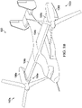
- FIGS. 1A and 1B show a tiltrotor aircraft 100 in accordance with an embodiment of the present invention.
- FIG. 1A illustrates the tiltrotor aircraft 100 in takeoff-and-landing mode or hover mode
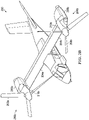
- FIG. 1B depicts the tiltrotor aircraft 100 in airplane or cruise mode.
- Tiltrotor aircraft 100 includes tilt rotor assemblies 102a and 102b that are carried by wings 104a and 104b, and are disposed at end portions 106a and 106b of wings 104a and 104b, respectively.
- Tilt rotor assemblies 102a and 102b include nacelles 108a and 108b, which carry the engines and transmissions of tiltrotor aircraft 100.
- Tilt rotor assemblies 102a and 102b move or rotate relative to wing members 104a and 104b between a helicopter or vertical-takeoff-and-landing mode in which tilt rotor assemblies 102a and 102b are tilted upward, such that tiltrotor aircraft 100 flies like a conventional helicopter; and an airplane or cruise mode in which tilt rotor assemblies 102a and 102b are tilted forward, such that tiltrotor aircraft 100 flies like a conventional propeller driven aircraft.
- FIGS. 2A and 2B show another tilt rotor aircraft 200 in accordance with an embodiment of the present invention.
- FIG. 2A depicts the tilt rotor aircraft 200 in a helicopter or vertical takeoff-and-landing mode
- Tilt rotor aircraft 200 includes rotor assemblies 202a and 202b that are carried by wings 204a and 204b, and are disposed at end portions 206a and 206b of wings 204a and 204b, respectively.
- Rotor assemblies 202a and 202b include nacelles 208a and 208b, which include the engines and transmissions of tilt rotor aircraft 200.
- the engines are fixed to the wing and do not rotate, rather, only the pylons 210a and 210b with the rotor assemblies 202a and 202b rotate.
- Tilt rotor assemblies 202a and 202b move and rotate relative to wing members 204a and 204b and the nacelles 208a and 208b.
- the tilt rotor assemblies 202a and 202b do not more relative to the wing members 204a and 204b. Instead, during the transition between a helicopter or hover mode only the pylons 210a and 210b with the rotor assemblies 202a and 202b rotate to redirect the thrust from the rotor assemblies 202a and 202b.
- the tilt rotor aircraft 200 is still able to fly like a conventional helicopter; and an airplane or cruise mode in which the rotors are tilted forward, such that tilt rotor aircraft 200 flies like a conventional propeller driven aircraft.
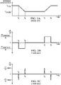
- FIGS. 3A, 3B, and 3C show graphs depicting an exemplary transition, using prior art systems and methods of changing rotor speeds, from a VTOL reference rotor speed R VTOL to a cruise reference rotor speed R CRUISE and then back to the VTOL reference rotor speed R VTOL , with time t on the horizontal axis and the reference rotor speed R on the vertical axis.
- the graph in FIG. 3A shows the reference rotor speed as it changes from R VTOL to R CRUISE during a first transitional time period and then back to R VTOL during a second transitional time period.
- 3B shows the rate of change of the reference rotor speed (i.e., acceleration/deceleration) as it changes during the transitional time periods, with time t on the horizontal axis and the rate of change of reference rotor speed, the first time derivative of the reference rotor speed, dR / dt, on the vertical axis.
- the transition from the R VTOL to R CRUISE takes place during transition period t A to t B
- the transition from R CRUISE to R VTOL takes place during transition period t C to t D .
- the dR / dt between t A and t B and between t C and t D represent constant rates of decrease and increase in R, here labeled dR INT1 / dt and dR INT2 / dt, respectively.
- the initial deceleration starts at 20 RPM/sec at t A and remains at 20 RPM/sec until reaching the target value of 80% RPM t B when the deceleration stops.
- R CRUISE e.g., 80% RPM
- the initial acceleration starts at 20 RPM/sec at t C and remains at 20 RPM/sec until reaching the target value of 100% RPM at t D when the acceleration stops.
- FIG. 3C shows the rate of change of torque ⁇ , d ⁇ /dt, during the transitions, showing large spikes at the times t A t B , t C , and t D of stopping or starting an acceleration or deceleration.
- FIG. 4 shows a diagram of a control law 400 for the operation of a rotor speed controller according to the prior art.
- the controller takes the current reference rotor speed 402 and executes a constant acceleration command (RPM/sec) in block 404 to increase or decrease the reference rotor speed at a fixed rate or constant acceleration.
- the controller compares 406 the new reference rotor speed to the actual rotor speed 408 to determine a RPM error X, proportional gain constant K p and integral gain constant K i (deg/sec) in block 410.
- a collective governor applies the proportional gain constant K p and the integral gain constant K i to the rotor speed error X and integrates the result to obtain a rotor pitch setting in block 412.
- the collective governor sends a collective blade angle command (deg) to the rotor system actuator in block 414.
- helicopters typically use a throttle governor and throttle actuator instead of a collective governor and blade pitch actuator, which are typically used in tiltrotor aircraft.
- the rapid acceleration/deceleration causes large rotor torque loads and abrupt jerks felt by the aircrews. Such high transient torque loads are detrimental, as previously discussed.
- FIG. 5 shows a diagram of a control law 500 for the operation of an embodiment of the invention.
- the controller takes the current reference rotor speed 502 and executes a variable acceleration command based on time or threshold from the reference in block 504 to increase or decrease the reference rotor speed in accordance with an acceleration-rate profile.
- the controller compares 506, the new reference rotor speed, to the actual rotor speed 508 to determine: a RPM error X, proportional gain constant K p and integral gain constant K i (deg/sec) in block 510. Thereafter, a collective governor applies the proportional gain constant K p and the integral gain constant K i to the rotor speed error X and integrates the result to obtain a rotor pitch setting in block 512.
- the collective governor sends a collective blade angle command (deg) to the rotor system actuator in block 514.
- a collective blade angle command deg
- the present invention can also be implemented using a throttle governor and throttle actuator, which are typically used in helicopters, instead of a collective governor and blade pitch actuator.
- FIG. 6A shows a flowchart of a method 600 in accordance with an embodiment of the present invention.
- the method 600 for controlling a rotor system provides a controller communicably coupled to the rotor system in block 602, and automatically changes a rotor speed of the rotor system from a first rotor speed in a first flight mode to a second rotor speed in a second flight mode over a time period using the controller in accordance with an acceleration-rate profile that varies over the time period in block 604.
- FIG. 6B is a block diagram of a system 650.
- the system 650 includes a controller 652 communicably coupled to an actuator 654, one or more sensors 656 and one or more flight controls 658.
- the rotor system 660 is communicably coupled to the actuator 654 and the one or more sensors 656.
- the controller 652 may also be communicably coupled to one or more remote devices 662.
- the controller 652 is configured to automatically change a rotor speed of the rotor system 660 from a first rotor speed in a first flight mode to a second rotor speed in a second flight mode over a time period in accordance with an acceleration-rate profile that varies over the time period.
- the system 650 may include other features as described in other portions of this description.
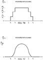
- FIGS. 7A , 7B and 7C illustrate a multi-segment linear acceleration-rate profile, a stair-stepped acceleration-rate profile, and a curved acceleration-rate profile, respectively, which may be used in embodiments of the invention.
- the skilled artisan will recognize that the profiles depicted are exemplary, and that embodiments of the invention include other acceleration-rate profiles.
- FIG. 7A a multi-segment linear profile is shown on a graph with time t on the horizontal axis and the rate of change of rotor speed R, dR / dt, on the vertical axis.
- FIG. 7B shows a stair-stepped profile, with time t on the horizontal axis and dR / dt on the vertical axis.
- FIG. 7C depicts a curved profile, with time t on the horizontal axis and dR / dt on the vertical axis.
- the profile of FIG. 7A is discussed in more detail below in connection with FIGS. 8A, 8B, and 8C , and 9A, 9B, and 9C .
- the rotor speed of a rotor system is changed by changing a rotor reference speed from one appropriate for one flight mode to another rotor reference speed that is appropriate for another flight mode.
- FIGS. 8A, 8B, and 8C show graphs depicting a transition from a VTOL reference rotor speed to a cruise reference rotor speed in accordance with an embodiment of the invention.
- the graph of FIG. 8A shows the reference rotor speed R as it changes from the VTOL reference speed R VTOL to the cruise reference rotor speed R CRUISE during three transition time periods.
- the reference rotor speed R is changed at a rate that gradually increases in absolute value from R VTOL to an intermediate rate of change dR INT / dt.
- R is changed at the steady rate dR INT / dt.
- R is changed at a rate that gradually decreases in absolute value from the intermediate rate of change dR INT / dt to a zero rate of change at the target reference rotor speed, R CRUISE .
- the graph of FIG. 8B shows the rate of change of the reference rotor speed, dR / dt, as R changes from the R VTOL to R CRUISE during the three transition periods depicted in the first graph of FIG. 8A .
- R is changed at the steady rate dR INT / dt.
- a typical value for R VTOL is about 400 rpm
- a typical value for R CRUISE is about 340 rpm
- a typical intermediate rate of change from R VTOL to R CRUISE is -20 rpm/sec
- a typical time interval for the reference rotor speed to change from an initial to a target value is about 4 seconds (prior art would be about 3 seconds).
- the present invention reduces the loads by approximately 80% while only increasing the transition time by approximately 30%. The rotor speeds, transaction time and load reduction will vary according to the specific aircraft specifications in which the invention is implemented.
- FIG. 8C shows the rate of change of torque ⁇ , d ⁇ / dt, during the transitions, with relatively small torque changes spread over times to to t 1 and t 2 to t 3 .
- FIGS. 9A and 9B show two graphs depicting a transition from R CRUISE to R VTOL in accordance with an embodiment of the invention.
- the graph of FIG. 9A shows the reference rotor speed as it changes from R CRUISE to R VTOL during three transition time periods.
- the reference rotor speed R is changed at a rate of change that gradually increases in absolute value from R CRUISE to an intermediate rate of change dR INT / dt.
- R is changed at the steady rate of change dR INT / dt.
- R is changed at a rate of change that gradually decreases in absolute value from the intermediate rate of change dR INT / dt to a zero rate of change at the target reference rotor speed, R VTOL .
- the graph of FIG. 9B shows the rate of change of the reference rotor speed, dR / dt, as R changes from the R CRUISE to R VTOL during the three transition periods depicted in the graph of FIG. 7A .
- R is changed at the steady rate dR INT ' / dt.
- FIG. 9C shows the rate of change of torque ⁇ , d ⁇ / dt, during the transitions, with relatively small torque changes spread over times t 0' to t 1' and t 2' to t 3' .
- d ⁇ / dt d ⁇ MAX3 / d t
- a typical value for R VTOL is about 400 rpm
- a typical value for R CRUISE is about 340 rpm
- a typical intermediate rate of change from R CRUISE to R VTOL , dR INT2 / dt is 20 rpm/sec
- a typical time interval for the reference rotor speed to change from an initial to a target value is about 4 seconds (prior art would be about 3 seconds).
- the actual values will vary according to the specific aircraft specifications in which the invention is implemented.
- the relatively moderate slopes of the dR / dt curves at the beginnings and ends of the transition periods in FIGS. 8A, 8B, 8C , 9A, 9B, and 9C represent relatively moderate acceleration and deceleration in the reference rotor speed R.
- FIGS. 8A, 8B, 8C , 9A, 9B, and 9C represent relatively moderate acceleration and deceleration in the reference rotor speed R.
- the initial deceleration increases at a rate of 1 RPM/sec at t 0 to 20 RPM/sec until reaching 95% RPM at t 1 , remains at 20 RPM/sec until reaching 85% RPM at t 2 , and decreases at a rate of 1 RPM/sec until the target value of 80% RPM is reached at t 3 when the deceleration stops.
- R VTOL e.g., 100% RPM
- R CRUISE e.g., 80% RPM
- the initial acceleration increases at a rate of 1 RPM/sec at t 0' to 20 RPM/sec until reaching 85% RPM at t 1' , remains at 20 RPM/sec until reaching 95% RPM at t 2' , and decreases at a rate of 1 RPM/sec until the target value of 100% RPM is reached at t 3' when the acceleration stops.
- acceleration/deceleration rate damper can be used as an acceleration/deceleration rate damper to smooth out aggressive or abrupt control movements by a pilot or autopilot.
- This acceleration/deceleration rate damper can be automatically or selectively engaged/disengaged based on the current flight operations of the aircraft.
- the acceleration/deceleration rate damper can be engaged during normal flight operations, but disengaged or disabled during combat or emergency flight operations.
- a variable acceleration command is provided to the collective or throttle governor.
- a time interval required to reach the target reference rotor speed, or a difference between the rotor speed measurement of the actual rotor speed and the target reference rotor speed, can be used to change the reference rotor speed as described in the descriptions of FIGS. 8A, 8B, 8C , 9A, 9B, and 9C .
- the total time interval to reach the target reference rotor speed can be divided into an initial interval (first 25% of the total time interval), intermediate interval (middle 50% of the total time interval), and final interval (last 25% of the total time interval).
- the controller compares the reference rotor speed, as determined by the control law for the relevant interval, to the actual rotor speed, derives the difference, called the rotor speed error (or rpm error), and sends the appropriate acceleration command to the governor.
- the governor then implements the received variable acceleration commands.
- VTOL reference rotor speed R VTOL it is convenient to refer to VTOL reference rotor speed R VTOL as 100%; cruise reference rotor speed R CRUISE is typically about 80% of R VTOL .
- Typical values for the reference rotor speeds under this criterion are a reduction of 20% of the VTOL reference rotor speed to reach the target cruise reference rotor speed, and thus 100% - 95% of the VTOL reference rotor speed for the initial interval, 95% - 85% of the VTOL reference rotor speed for the intermediate interval, and 85% - 80% of the VTOL reference rotor speed for the final interval.
- Typical time values for the intervals involved are about 4.0 seconds to reach the target reference rotor speed, and about 1.0 second for the initial interval, about 2.0 seconds for the intermediate interval, and about 1.0 second for the final interval.
- the gradually changing acceleration and deceleration of the reference rotor speed in the initial and final intervals subject the rotor system to considerably less torque than the abrupt acceleration and deceleration of the reference rotor speed in typical current systems and methods.
- FIG. 10 illustrates a graph comparing data from changes in mast torque due to prior art changes in reference rotor speed and changes according to an embodiment of the present invention.
- the vertical axis represents mast torque in foot-pounds and the horizontal axis represents time in seconds over a period covering decreases and increases in reference rotor speeds.
- the prior art curve shows abrupt changes in mast torque due to an abrupt reduction of reference rotor speed between 2 and 3 seconds and due to an abrupt increase of reference rotor speed between 6 and 7 seconds.
- the curve 1002, generated by use of an embodiment of the present invention, shows a more gradual decrease in mast torque due to more gradual decreases in reference rotor speed between 2 and 3 seconds and between 4 and 5 seconds.
- the curve 1002 continues, showing a more gradual increase in mast torque between 6 and 7 seconds and another more gradual increase between 8 and 9 seconds due to more gradual increases in reference rotor speed.
- This graph illustrates changes in reference rotor speeds according to an embodiment of the present invention following a stair-stepped curve similar to that shown in FIG. 7B .
- Embodiments of the present invention may be implemented in a variety of ways.
- the controller may include a rotor speed controller such as a collective governor or a throttle governor, or it may include a flight control computer.
- a rotor speed controller such as a collective governor or a throttle governor or a flight control computer may include the controller.
- Embodiments may be implemented as digital or analog systems and methods.
- the duration of the transition time beginning when the reference rotor speed begins changing and ends when the reference rotor speed reaches the target reference rotor speed, may be selectable during flight by a pilot or by a remote operator.
- the criteria to which the reference rotor speed is changed over time that is, (1) the time interval required to reach the target reference rotor speed or (2) the acceleration of the target reference rotor speed, may be selectable during flight by a pilot or by a remote operator.
- Embodiments of the invention may also be used in conventional rotorcraft, e.g., helicopters or other aircraft, in which more than one reference rotor speed is desirable.
- embodiments of the invention allow for changes in rotor speeds from one flight mode to another without the abrupt transient torque loads encountered with prior art methods and systems in tiltrotor aircraft by reducing or eliminating rapid changes in the acceleration at which rotor speed changes are started and stopped.
Landscapes
- Engineering & Computer Science (AREA)
- Aviation & Aerospace Engineering (AREA)
- Mechanical Engineering (AREA)
- Radar, Positioning & Navigation (AREA)
- Remote Sensing (AREA)
- Physics & Mathematics (AREA)
- General Physics & Mathematics (AREA)
- Automation & Control Theory (AREA)
- Control Of Turbines (AREA)
- Toys (AREA)
- Control Of Position, Course, Altitude, Or Attitude Of Moving Bodies (AREA)
Claims (17)
- Verfahren (600) zum Steuern eines Rotorsystems (660) für ein Kipprotorflugzeug (100, 200), wobei das Verfahren (600) Folgendes umfasst:Bereitstellen (602) einer Steuereinheit (652), die kommunizierbar mit dem Rotorsystem (660) gekoppelt ist; undEmpfangen eines Signals bei der Steuereinheit, um das Rotorsystem (660) von einem ersten Flugmodus zu einem zweiten Flugmodus zu ändern;automatisches Ändern (604) einer Rotorgeschwindigkeit des Rotorsystems (660) von einer ersten Rotorgeschwindigkeit in dem ersten Flugmodus zu einer zweiten Rotorgeschwindigkeit in dem zweiten Flugmodus über eine Zeitdauer unter Verwendung der Steuereinheit (652) in Übereinstimmung mit einem Beschleunigungsratenprofil für das Rotorsystem (660), das sich über die Zeitdauer ändert; wobeidas Rotorsystem (660) Folgendes ist: (a) im Allgemeinen parallel zu einer Gierachse des Kipprotorflugzeugs (100, 200) in dem ersten Flugmodus und im Allgemeinen parallel zu einer Rollachse des Kipprotorflugzeugs (100, 200) in dem zweiten Flugmodus, oder (b) im Allgemeinen parallel zu einer Rollachse des Kipprotorflugzeugs (100, 200) in dem ersten Flugmodus und im Allgemeinen parallel zu einer Gierachse des Kipprotorflugzeugs (100, 200) in dem zweiten Flugmodus.
- Einrichtung (650) für ein Kipprotorflugzeug (100, 200), wobei die Einrichtung (650) Folgendes umfasst:ein Rotorsystem (660);eine Steuereinheit (652), die betriebsfähig mit dem Rotorsystem (660) gekoppelt ist und betriebsfähig konfiguriert ist, ein Signal zu empfangen, das Rotorsystem (66) von einem ersten Flugmodus zu einem zweiten Flugmodus zu ändern und automatisch eine Rotorgeschwindigkeit des Rotorsystems (660) von einer ersten Rotorgeschwindigkeit in dem ersten Flugmodus zu einer zweiten Rotorgeschwindigkeit in dem zweiten Flugmodus über eine Zeitdauer in Übereinstimmung mit einem Beschleunigungsratenprofil für das Rotorsystem (660), das über die Zeitdauer variiert, zu ändern; wobeidas Rotorsystem (660) Folgendes ist: (a) im Allgemeinen parallel zu einer Gierachse des Kipprotorflugzeugs (100, 200) in dem ersten Flugmodus und im Allgemeinen parallel zu einer Rollachse des Kipprotorflugzeugs (100, 200) in dem zweiten Flugmodus, oder (b) im Allgemeinen parallel zu einer Rollachse des Kipprotorflugzeugs (100, 200) in dem ersten Flugmodus und im Allgemeinen parallel zu einer Gierachse des Kipprotorflugzeugs (100, 200) in dem zweiten Flugmodus.
- Einrichtung (650) nach Anspruch 2, weiter umfassend eine oder mehrere Steuervorrichtungen (658) oder eine oder mehrere ferne Vorrichtungen (662), die kommunizierbar mit der Steuereinheit (652) gekoppelt sind, die betriebsfähig konfiguriert sind, ein Signal, das Rotorsystem (660) von der ersten Rotorgeschwindigkeit zu der zweiten Rotorgeschwindigkeit zu ändern, zu senden oder zu empfangen.
- Verfahren (600) nach Anspruch 1, weiter umfassend Ermitteln des Beschleunigungsratenprofils basierend auf einem oder mehreren Betriebsparametern, die einen oder mehrere von einem Rotorsystemleistungsparameter, einem Flugzeugbetriebsmodusparameter, einem Flugzeugeigenschaftsparameter oder einem Umgebungsparameter umfassen; oder
Einrichtung (650) nach Anspruch 2 oder nach Anspruch 3, wobei die Steuereinheit (652) das Beschleunigungsratenprofil basierend auf einem oder mehreren Betriebsparametern ermittelt, die einen oder mehrere von einem Rotorsystemleistungsparameter, einem Flugzeugbetriebsmodusparameter, einem Flugzeugeigenschaftsparameter oder einem Umgebungsparameter umfassen. - Verfahren (600) nach Anspruch 4, weiter umfassend Ermitteln des einen oder der mehreren Betriebsparameter basierend auf einem oder mehreren Sensoren (656), die kommunizierbar mit der Steuereinheit (652) gekoppelt sind, einer oder mehreren Flugsteuerungen (658), die kommunizierbar mit der Steuereinheit (652) gekoppelt sind, oder einem oder mehreren Signalen von einer oder mehreren fernen Vorrichtungen (662), die kommunizierbar mit der Steuereinheit (652) gekoppelt sind.
- Verfahren (600) nach Anspruch 1 oder nach einem vorstehenden Verfahrensanspruch, oder Einrichtung (650) nach Anspruch 2 oder nach einem vorstehenden Einrichtungsanspruch, wobei das Beschleunigungsratenprofil ein mehrteiliges lineares Profil, ein Kurvenprofil, ein Stufenprofil oder eine Kombination davon umfasst.
- Verfahren (600) nach Anspruch 6, wobei das Beschleunigungsratenprofil zumindest ein Kurvensegment und zumindest ein lineares Segment umfasst; oder
Einrichtung (650) nach Anspruch 2 oder nach einem vorstehenden Einrichtungsanspruch, wobei das Beschleunigungsratenprofil zumindest ein Kurvensegment und zumindest ein lineares Segment umfasst. - Kipprotorflugzeug (100, 200), das Folgendes umfasst:einen Rumpf;einen oder mehrere Motoren, die mit dem Rumpf gekoppelt sind, unddie Einrichtung (650) nach Anspruch 2, wobei das Rotorsystem (660) mit dem einen oder den mehreren Motoren gekoppelt ist.
- Kipprotorflugzeug (100, 200) nach Anspruch 8, weiter umfassend eine oder mehrere Steuervorrichtungen (658) oder eine oder mehrere ferne Vorrichtungen (662), die kommunizierbar mit der Steuereinheit (652) gekoppelt sind, die betriebsfähig konfiguriert sind, ein Signal, das Rotorsystem (660) von der ersten Rotorgeschwindigkeit zu der zweiten Rotorgeschwindigkeit zu ändern, zu senden oder zu empfangen.
- Verfahren (600) nach Anspruch 1 oder nach einem vorstehenden Verfahrensanspruch, oder Einrichtung (650) nach Anspruch 2 oder nach einem vorstehenden Einrichtungsanspruch, oder das Kipprotorflugzeug (100, 200) nach Anspruch 8 oder nach Anspruch 9, wobei das Beschleunigungsratenprofil eine ansteigende Beschleunigungsrate für einen ersten Abschnitt der Zeitdauer, eine konstante Beschleunigungsrate für einen zweiten Abschnitt der Zeitdauer und eine sinkende Beschleunigungsrate für einen dritten Abschnitt der Zeitdauer umfasst.
- Verfahren (600) nach Anspruch 1 oder nach einem vorstehenden Verfahrensanspruch, wobei die Rotorgeschwindigkeit über die Zeitdauer gemäß einem Abschnitt der in der Zeitdauer verbleibenden Zeitdauer oder einer Differenz zwischen einer tatsächlichen Rotorgeschwindigkeit und einer Referenzrotorgeschwindigkeit geändert wird; oder
Einrichtung (650) nach Anspruch 2 oder nach einem vorstehenden Einrichtungsanspruch, wobei die Steuereinheit (652) die Rotorgeschwindigkeit über die Zeitdauer gemäß einem Abschnitt der in der Zeitdauer verbleibenden Zeitdauer oder einer Differenz zwischen einer tatsächlichen Rotorgeschwindigkeit und einer Referenzrotorgeschwindigkeit ändert. - Verfahren (600) nach Anspruch 1 oder nach einem vorstehenden Verfahrensanspruch, wobei das Beschleunigungsratenprofil unter Verwendung einer Steuerregel basierend auf einer Referenzrotorgeschwindigkeit und einer tatsächlichen Rotorgeschwindigkeit implementiert wird; oder
die Einrichtung (650) nach Anspruch 2 oder nach einem vorstehenden Einrichtungsanspruch, wobei die Steuereinheit (652) das Beschleunigungsratenprofil unter Verwendung einer Steuerregel basierend auf einer Referenzrotorgeschwindigkeit und einer tatsächlichen Rotorgeschwindigkeit implementiert. - Verfahren (600) nach Anspruch 12, wobei die Steuerregel einen variablen Beschleunigungsbefehl basierend auf einem Abschnitt der in der Zeitdauer verbleibenden Zeitdauer oder einer Differenz zwischen der tatsächlichen Rotorgeschwindigkeit und der Referenzrotorgeschwindigkeit umfasst.
- Verfahren (600) nach Anspruch 1 oder nach einem vorstehenden Verfahrensanspruch, oder Einrichtung (650) nach Anspruch 2 oder nach einem vorstehenden Einrichtungsanspruch, wobei die Steuereinheit eine analoge Vorrichtung, eine digitale Vorrichtung oder eine Kombination davon ist.
- Verfahren (600) nach Anspruch 1 oder nach einem vorstehenden Verfahrensanspruch, wobei die Rotorgeschwindigkeit unter Verwendung der Steuereinheit (652) und zumindest eines von einem Sammelregler oder einem Gasregler geändert wird; oder
Einrichtung (650) nach Anspruch 3, wobei die eine oder mehreren Steuervorrichtungen (658) einen Sammelregler oder einen Gasregler umfassen. - Verfahren (600) nach Anspruch 1 oder nach einem vorstehenden Verfahrensanspruch, wobei die Rotorgeschwindigkeit geändert wird, indem eine Referenzrotorgeschwindigkeit geändert wird.
- Einrichtung (650) nach Anspruch 2 oder nach einem vorstehenden Einrichtungsanspruch, oder Kipprotorflugzeug (100, 200) nach Anspruch 8 oder nach Anspruch 9 oder nach Anspruch 10, weiter umfassend einen oder mehrere Sensoren (656), die kommunizierbar mit der Steuereinheit (652) und dem Rotorsystem (660) gekoppelt sind.
Priority Applications (1)
| Application Number | Priority Date | Filing Date | Title |
|---|---|---|---|
| EP22196171.7A EP4134300A3 (de) | 2018-04-24 | 2019-04-18 | Verfahren und system zur steuerung der rotordrehzahlen von rotorsystemen |
Applications Claiming Priority (1)
| Application Number | Priority Date | Filing Date | Title |
|---|---|---|---|
| US15/960,732 US11072434B2 (en) | 2018-04-24 | 2018-04-24 | Method and system for controlling rotor speeds of rotor systems |
Related Child Applications (1)
| Application Number | Title | Priority Date | Filing Date |
|---|---|---|---|
| EP22196171.7A Division EP4134300A3 (de) | 2018-04-24 | 2019-04-18 | Verfahren und system zur steuerung der rotordrehzahlen von rotorsystemen |
Publications (2)
| Publication Number | Publication Date |
|---|---|
| EP3560833A1 EP3560833A1 (de) | 2019-10-30 |
| EP3560833B1 true EP3560833B1 (de) | 2022-10-12 |
Family
ID=66239891
Family Applications (2)
| Application Number | Title | Priority Date | Filing Date |
|---|---|---|---|
| EP22196171.7A Pending EP4134300A3 (de) | 2018-04-24 | 2019-04-18 | Verfahren und system zur steuerung der rotordrehzahlen von rotorsystemen |
| EP19170241.4A Active EP3560833B1 (de) | 2018-04-24 | 2019-04-18 | Verfahren und system zur steuerung der rotordrehzahlen von rotorsystemen |
Family Applications Before (1)
| Application Number | Title | Priority Date | Filing Date |
|---|---|---|---|
| EP22196171.7A Pending EP4134300A3 (de) | 2018-04-24 | 2019-04-18 | Verfahren und system zur steuerung der rotordrehzahlen von rotorsystemen |
Country Status (2)
| Country | Link |
|---|---|
| US (2) | US11072434B2 (de) |
| EP (2) | EP4134300A3 (de) |
Families Citing this family (6)
| Publication number | Priority date | Publication date | Assignee | Title |
|---|---|---|---|---|
| US10946972B2 (en) * | 2017-12-08 | 2021-03-16 | Pratt & Whitney Canada Corp. | Method and system for controlling thrust of an engine |
| US11072434B2 (en) | 2018-04-24 | 2021-07-27 | Textron Innovations Inc. | Method and system for controlling rotor speeds of rotor systems |
| WO2020093264A1 (zh) * | 2018-11-07 | 2020-05-14 | 大连理工大学 | 一种航空发动机过渡态控制规律优化的设计方法 |
| JP6561272B1 (ja) * | 2018-12-07 | 2019-08-21 | 株式会社プロドローン | 回転翼航空機 |
| US12055950B2 (en) * | 2019-09-16 | 2024-08-06 | Honeywell International Inc. | Systems and methods for energy managed autoflight guidance using potential flight path angle |
| USD1090401S1 (en) * | 2022-01-06 | 2025-08-26 | REGENT Craft Inc. | Winged vehicle, toy, and/or replica model thereof |
Citations (2)
| Publication number | Priority date | Publication date | Assignee | Title |
|---|---|---|---|---|
| US5017089A (en) * | 1989-04-11 | 1991-05-21 | United Technologies Corporation | Propeller speed governor having a derivative inhibit at high flight speeds |
| US20160229547A1 (en) * | 2013-10-11 | 2016-08-11 | Unison Industries, Llc | Method and apparatus for controlling a turboprop engine |
Family Cites Families (22)
| Publication number | Priority date | Publication date | Assignee | Title |
|---|---|---|---|---|
| US4071811A (en) * | 1976-03-01 | 1978-01-31 | Arlyle Floyd Irwin | Model helicopter throttle governor/collective pitch control apparatus |
| US5029441A (en) | 1989-09-20 | 1991-07-09 | United Technologies Corporation | Dynamic compensation to n-dot schedules |
| JP3222298B2 (ja) | 1993-12-24 | 2001-10-22 | 株式会社福島製作所 | 吊具の自動旋回位置決め方法および自動旋回位置決め装置を備えた吊具 |
| JPH08322298A (ja) | 1995-05-24 | 1996-12-03 | Yamaha Motor Co Ltd | 風力発電装置 |
| US6140803A (en) * | 1999-04-13 | 2000-10-31 | Siemens Westinghouse Power Corporation | Apparatus and method for synchronizing a synchronous condenser with a power generation system |
| GB0105502D0 (en) * | 2001-03-06 | 2001-04-25 | Switched Reluctance Drives Ltd | Compensation for variable voltage |
| US7180253B2 (en) * | 2003-09-30 | 2007-02-20 | Rockwell Automation Technologies, Inc. | Method and system for generating multi-dimensional motion profiles |
| US7002318B1 (en) * | 2004-09-23 | 2006-02-21 | General Motors Corporation | Position sensor fault tolerant control for automotive propulsion system |
| US9235217B2 (en) * | 2005-10-03 | 2016-01-12 | Sikorsky Aircraft Corporation | Automatic dual rotor speed control for helicopters |
| US7931231B2 (en) * | 2007-05-18 | 2011-04-26 | Sikorsky Aircraft Corporation | Engine anticipation for rotary-wing aircraft |
| FR2916418B1 (fr) * | 2007-05-22 | 2009-08-28 | Eurocopter France | Helicoptere hybride rapide a grande distance franchissable. |
| US8133155B2 (en) * | 2009-07-14 | 2012-03-13 | Bell Helicopter Textron Inc. | Multi-ratio rotorcraft drive system and a method of changing gear ratios thereof |
| US9051055B2 (en) * | 2013-03-07 | 2015-06-09 | Bell Helicopter Textron Inc. | System and method of adaptively governing rotor speed for optimal performance |
| US9290266B2 (en) * | 2013-03-15 | 2016-03-22 | Bell Helicopter Textron Inc. | Speed control assembly and methods of using same |
| EP3734816A1 (de) * | 2013-05-09 | 2020-11-04 | Rockwell Automation Technologies, Inc. | Gesteuertes bewegungssystem mit verbesserter spurkonfiguration |
| DK2851559T3 (en) | 2013-09-18 | 2018-05-07 | Siemens Ag | Method and device for controlling the rotor movement of a wind turbine rotor |
| US20160023755A1 (en) * | 2014-05-05 | 2016-01-28 | King Fahd University Of Petroleum And Minerals | System and method for control of quadrotor air vehicles with tiltable rotors |
| WO2017115120A1 (en) | 2015-12-29 | 2017-07-06 | Hangzhou Zero Zero Technology Co., Ltd. | System and method for automated aerial system operation |
| US10150561B2 (en) * | 2016-02-01 | 2018-12-11 | King Fahd University Of Petroleum And Minerals | System and method of operation of twin-tiltrotor helicopter |
| US10189559B2 (en) * | 2016-11-22 | 2019-01-29 | Sikorsky Aircraft Corporation | Rotor speed control using a feed-forward rotor speed command |
| US10946954B2 (en) * | 2017-07-13 | 2021-03-16 | Bell Helicopter Textron Inc. | Variable-speed drive system for tiltrotor with fixed engine and rotating proprotor |
| US11072434B2 (en) | 2018-04-24 | 2021-07-27 | Textron Innovations Inc. | Method and system for controlling rotor speeds of rotor systems |
-
2018
- 2018-04-24 US US15/960,732 patent/US11072434B2/en active Active
-
2019
- 2019-04-18 EP EP22196171.7A patent/EP4134300A3/de active Pending
- 2019-04-18 EP EP19170241.4A patent/EP3560833B1/de active Active
-
2021
- 2021-05-28 US US17/333,745 patent/US12312093B2/en active Active
Patent Citations (2)
| Publication number | Priority date | Publication date | Assignee | Title |
|---|---|---|---|---|
| US5017089A (en) * | 1989-04-11 | 1991-05-21 | United Technologies Corporation | Propeller speed governor having a derivative inhibit at high flight speeds |
| US20160229547A1 (en) * | 2013-10-11 | 2016-08-11 | Unison Industries, Llc | Method and apparatus for controlling a turboprop engine |
Also Published As
| Publication number | Publication date |
|---|---|
| US11072434B2 (en) | 2021-07-27 |
| EP4134300A3 (de) | 2023-05-24 |
| EP4134300A2 (de) | 2023-02-15 |
| EP3560833A1 (de) | 2019-10-30 |
| US12312093B2 (en) | 2025-05-27 |
| US20190322380A1 (en) | 2019-10-24 |
| US20220024573A1 (en) | 2022-01-27 |
Similar Documents
| Publication | Publication Date | Title |
|---|---|---|
| EP3560833B1 (de) | Verfahren und system zur steuerung der rotordrehzahlen von rotorsystemen | |
| US10877487B2 (en) | Pitch and thrust control for compound aircraft | |
| CN110127041B (zh) | 用于旋翼飞行器自旋进入辅助的系统和方法 | |
| US7931238B2 (en) | Automatic velocity control system for aircraft | |
| CA2664195C (en) | Automatic conversion system for tiltrotor aircraft | |
| US10479491B2 (en) | System and method for rotorcraft collective power hold | |
| US11599111B2 (en) | Reverse tactile cue for rotorcraft rotor overspeed protection | |
| US12054245B2 (en) | Optimizing usage of supplemental engine power | |
| EP3561631B1 (de) | Neigungs- und schubregelung für verbundflugzeuge | |
| CN115427304B (zh) | 用于直升机的混合推进系统 | |
| US20220195946A1 (en) | Inlet Configuration Enabling Rapid In-Flight Engine Restart | |
| EP2813427B1 (de) | Auf Drehmoment basierendes Verfahren zur Begrenzung der Vertikalachsenzunahme | |
| US11685515B2 (en) | Active horizontal stabilizer for high speed rotorcraft | |
| RU2380280C2 (ru) | Автоматическая система управления скоростью для воздушного судна | |
| BR102019007805B1 (pt) | Circuito de controle, método para controlar uma aeronave, aparelho e sistema para uma aeronave | |
| Blake | Research opportunities for rotorcraft |
Legal Events
| Date | Code | Title | Description |
|---|---|---|---|
| STAA | Information on the status of an ep patent application or granted ep patent |
Free format text: STATUS: EXAMINATION IS IN PROGRESS |
|
| PUAI | Public reference made under article 153(3) epc to a published international application that has entered the european phase |
Free format text: ORIGINAL CODE: 0009012 |
|
| 17P | Request for examination filed |
Effective date: 20190418 |
|
| AK | Designated contracting states |
Kind code of ref document: A1 Designated state(s): AL AT BE BG CH CY CZ DE DK EE ES FI FR GB GR HR HU IE IS IT LI LT LU LV MC MK MT NL NO PL PT RO RS SE SI SK SM TR |
|
| AX | Request for extension of the european patent |
Extension state: BA ME |
|
| GRAP | Despatch of communication of intention to grant a patent |
Free format text: ORIGINAL CODE: EPIDOSNIGR1 |
|
| STAA | Information on the status of an ep patent application or granted ep patent |
Free format text: STATUS: GRANT OF PATENT IS INTENDED |
|
| RIC1 | Information provided on ipc code assigned before grant |
Ipc: B64C 27/04 20060101ALN20220329BHEP Ipc: B64C 29/00 20060101ALN20220329BHEP Ipc: G05D 1/08 20060101ALI20220329BHEP Ipc: B64D 31/06 20060101ALI20220329BHEP Ipc: B64C 27/57 20060101AFI20220329BHEP |
|
| INTG | Intention to grant announced |
Effective date: 20220504 |
|
| GRAS | Grant fee paid |
Free format text: ORIGINAL CODE: EPIDOSNIGR3 |
|
| GRAA | (expected) grant |
Free format text: ORIGINAL CODE: 0009210 |
|
| STAA | Information on the status of an ep patent application or granted ep patent |
Free format text: STATUS: THE PATENT HAS BEEN GRANTED |
|
| RAP1 | Party data changed (applicant data changed or rights of an application transferred) |
Owner name: TEXTRON INNOVATIONS INC. |
|
| AK | Designated contracting states |
Kind code of ref document: B1 Designated state(s): AL AT BE BG CH CY CZ DE DK EE ES FI FR GB GR HR HU IE IS IT LI LT LU LV MC MK MT NL NO PL PT RO RS SE SI SK SM TR |
|
| REG | Reference to a national code |
Ref country code: GB Ref legal event code: FG4D |
|
| REG | Reference to a national code |
Ref country code: CH Ref legal event code: EP |
|
| REG | Reference to a national code |
Ref country code: DE Ref legal event code: R096 Ref document number: 602019020441 Country of ref document: DE |
|
| REG | Reference to a national code |
Ref country code: IE Ref legal event code: FG4D |
|
| REG | Reference to a national code |
Ref country code: AT Ref legal event code: REF Ref document number: 1524035 Country of ref document: AT Kind code of ref document: T Effective date: 20221115 |
|
| REG | Reference to a national code |
Ref country code: LT Ref legal event code: MG9D |
|
| REG | Reference to a national code |
Ref country code: NL Ref legal event code: MP Effective date: 20221012 |
|
| REG | Reference to a national code |
Ref country code: AT Ref legal event code: MK05 Ref document number: 1524035 Country of ref document: AT Kind code of ref document: T Effective date: 20221012 |
|
| PG25 | Lapsed in a contracting state [announced via postgrant information from national office to epo] |
Ref country code: NL Free format text: LAPSE BECAUSE OF FAILURE TO SUBMIT A TRANSLATION OF THE DESCRIPTION OR TO PAY THE FEE WITHIN THE PRESCRIBED TIME-LIMIT Effective date: 20221012 |
|
| PG25 | Lapsed in a contracting state [announced via postgrant information from national office to epo] |
Ref country code: SE Free format text: LAPSE BECAUSE OF FAILURE TO SUBMIT A TRANSLATION OF THE DESCRIPTION OR TO PAY THE FEE WITHIN THE PRESCRIBED TIME-LIMIT Effective date: 20221012 Ref country code: PT Free format text: LAPSE BECAUSE OF FAILURE TO SUBMIT A TRANSLATION OF THE DESCRIPTION OR TO PAY THE FEE WITHIN THE PRESCRIBED TIME-LIMIT Effective date: 20230213 Ref country code: NO Free format text: LAPSE BECAUSE OF FAILURE TO SUBMIT A TRANSLATION OF THE DESCRIPTION OR TO PAY THE FEE WITHIN THE PRESCRIBED TIME-LIMIT Effective date: 20230112 Ref country code: LT Free format text: LAPSE BECAUSE OF FAILURE TO SUBMIT A TRANSLATION OF THE DESCRIPTION OR TO PAY THE FEE WITHIN THE PRESCRIBED TIME-LIMIT Effective date: 20221012 Ref country code: FI Free format text: LAPSE BECAUSE OF FAILURE TO SUBMIT A TRANSLATION OF THE DESCRIPTION OR TO PAY THE FEE WITHIN THE PRESCRIBED TIME-LIMIT Effective date: 20221012 Ref country code: ES Free format text: LAPSE BECAUSE OF FAILURE TO SUBMIT A TRANSLATION OF THE DESCRIPTION OR TO PAY THE FEE WITHIN THE PRESCRIBED TIME-LIMIT Effective date: 20221012 Ref country code: AT Free format text: LAPSE BECAUSE OF FAILURE TO SUBMIT A TRANSLATION OF THE DESCRIPTION OR TO PAY THE FEE WITHIN THE PRESCRIBED TIME-LIMIT Effective date: 20221012 |
|
| PG25 | Lapsed in a contracting state [announced via postgrant information from national office to epo] |
Ref country code: RS Free format text: LAPSE BECAUSE OF FAILURE TO SUBMIT A TRANSLATION OF THE DESCRIPTION OR TO PAY THE FEE WITHIN THE PRESCRIBED TIME-LIMIT Effective date: 20221012 Ref country code: PL Free format text: LAPSE BECAUSE OF FAILURE TO SUBMIT A TRANSLATION OF THE DESCRIPTION OR TO PAY THE FEE WITHIN THE PRESCRIBED TIME-LIMIT Effective date: 20221012 Ref country code: LV Free format text: LAPSE BECAUSE OF FAILURE TO SUBMIT A TRANSLATION OF THE DESCRIPTION OR TO PAY THE FEE WITHIN THE PRESCRIBED TIME-LIMIT Effective date: 20221012 Ref country code: IS Free format text: LAPSE BECAUSE OF FAILURE TO SUBMIT A TRANSLATION OF THE DESCRIPTION OR TO PAY THE FEE WITHIN THE PRESCRIBED TIME-LIMIT Effective date: 20230212 Ref country code: HR Free format text: LAPSE BECAUSE OF FAILURE TO SUBMIT A TRANSLATION OF THE DESCRIPTION OR TO PAY THE FEE WITHIN THE PRESCRIBED TIME-LIMIT Effective date: 20221012 Ref country code: GR Free format text: LAPSE BECAUSE OF FAILURE TO SUBMIT A TRANSLATION OF THE DESCRIPTION OR TO PAY THE FEE WITHIN THE PRESCRIBED TIME-LIMIT Effective date: 20230113 |
|
| P01 | Opt-out of the competence of the unified patent court (upc) registered |
Effective date: 20230602 |
|
| REG | Reference to a national code |
Ref country code: DE Ref legal event code: R097 Ref document number: 602019020441 Country of ref document: DE |
|
| PG25 | Lapsed in a contracting state [announced via postgrant information from national office to epo] |
Ref country code: SM Free format text: LAPSE BECAUSE OF FAILURE TO SUBMIT A TRANSLATION OF THE DESCRIPTION OR TO PAY THE FEE WITHIN THE PRESCRIBED TIME-LIMIT Effective date: 20221012 Ref country code: RO Free format text: LAPSE BECAUSE OF FAILURE TO SUBMIT A TRANSLATION OF THE DESCRIPTION OR TO PAY THE FEE WITHIN THE PRESCRIBED TIME-LIMIT Effective date: 20221012 Ref country code: EE Free format text: LAPSE BECAUSE OF FAILURE TO SUBMIT A TRANSLATION OF THE DESCRIPTION OR TO PAY THE FEE WITHIN THE PRESCRIBED TIME-LIMIT Effective date: 20221012 Ref country code: DK Free format text: LAPSE BECAUSE OF FAILURE TO SUBMIT A TRANSLATION OF THE DESCRIPTION OR TO PAY THE FEE WITHIN THE PRESCRIBED TIME-LIMIT Effective date: 20221012 Ref country code: CZ Free format text: LAPSE BECAUSE OF FAILURE TO SUBMIT A TRANSLATION OF THE DESCRIPTION OR TO PAY THE FEE WITHIN THE PRESCRIBED TIME-LIMIT Effective date: 20221012 |
|
| PLBE | No opposition filed within time limit |
Free format text: ORIGINAL CODE: 0009261 |
|
| STAA | Information on the status of an ep patent application or granted ep patent |
Free format text: STATUS: NO OPPOSITION FILED WITHIN TIME LIMIT |
|
| PG25 | Lapsed in a contracting state [announced via postgrant information from national office to epo] |
Ref country code: SK Free format text: LAPSE BECAUSE OF FAILURE TO SUBMIT A TRANSLATION OF THE DESCRIPTION OR TO PAY THE FEE WITHIN THE PRESCRIBED TIME-LIMIT Effective date: 20221012 Ref country code: AL Free format text: LAPSE BECAUSE OF FAILURE TO SUBMIT A TRANSLATION OF THE DESCRIPTION OR TO PAY THE FEE WITHIN THE PRESCRIBED TIME-LIMIT Effective date: 20221012 |
|
| 26N | No opposition filed |
Effective date: 20230713 |
|
| PG25 | Lapsed in a contracting state [announced via postgrant information from national office to epo] |
Ref country code: SI Free format text: LAPSE BECAUSE OF FAILURE TO SUBMIT A TRANSLATION OF THE DESCRIPTION OR TO PAY THE FEE WITHIN THE PRESCRIBED TIME-LIMIT Effective date: 20221012 |
|
| REG | Reference to a national code |
Ref country code: CH Ref legal event code: PL |
|
| PG25 | Lapsed in a contracting state [announced via postgrant information from national office to epo] |
Ref country code: LU Free format text: LAPSE BECAUSE OF NON-PAYMENT OF DUE FEES Effective date: 20230418 |
|
| REG | Reference to a national code |
Ref country code: BE Ref legal event code: MM Effective date: 20230430 |
|
| PG25 | Lapsed in a contracting state [announced via postgrant information from national office to epo] |
Ref country code: MC Free format text: LAPSE BECAUSE OF FAILURE TO SUBMIT A TRANSLATION OF THE DESCRIPTION OR TO PAY THE FEE WITHIN THE PRESCRIBED TIME-LIMIT Effective date: 20221012 |
|
| PG25 | Lapsed in a contracting state [announced via postgrant information from national office to epo] |
Ref country code: MC Free format text: LAPSE BECAUSE OF FAILURE TO SUBMIT A TRANSLATION OF THE DESCRIPTION OR TO PAY THE FEE WITHIN THE PRESCRIBED TIME-LIMIT Effective date: 20221012 Ref country code: LI Free format text: LAPSE BECAUSE OF NON-PAYMENT OF DUE FEES Effective date: 20230430 Ref country code: CH Free format text: LAPSE BECAUSE OF NON-PAYMENT OF DUE FEES Effective date: 20230430 |
|
| REG | Reference to a national code |
Ref country code: IE Ref legal event code: MM4A |
|
| PG25 | Lapsed in a contracting state [announced via postgrant information from national office to epo] |
Ref country code: BE Free format text: LAPSE BECAUSE OF NON-PAYMENT OF DUE FEES Effective date: 20230430 |
|
| PG25 | Lapsed in a contracting state [announced via postgrant information from national office to epo] |
Ref country code: IE Free format text: LAPSE BECAUSE OF NON-PAYMENT OF DUE FEES Effective date: 20230418 |
|
| PG25 | Lapsed in a contracting state [announced via postgrant information from national office to epo] |
Ref country code: IE Free format text: LAPSE BECAUSE OF NON-PAYMENT OF DUE FEES Effective date: 20230418 |
|
| PG25 | Lapsed in a contracting state [announced via postgrant information from national office to epo] |
Ref country code: BG Free format text: LAPSE BECAUSE OF FAILURE TO SUBMIT A TRANSLATION OF THE DESCRIPTION OR TO PAY THE FEE WITHIN THE PRESCRIBED TIME-LIMIT Effective date: 20221012 |
|
| PG25 | Lapsed in a contracting state [announced via postgrant information from national office to epo] |
Ref country code: BG Free format text: LAPSE BECAUSE OF FAILURE TO SUBMIT A TRANSLATION OF THE DESCRIPTION OR TO PAY THE FEE WITHIN THE PRESCRIBED TIME-LIMIT Effective date: 20221012 |
|
| PGFP | Annual fee paid to national office [announced via postgrant information from national office to epo] |
Ref country code: DE Payment date: 20250429 Year of fee payment: 7 |
|
| PGFP | Annual fee paid to national office [announced via postgrant information from national office to epo] |
Ref country code: GB Payment date: 20250428 Year of fee payment: 7 |
|
| PGFP | Annual fee paid to national office [announced via postgrant information from national office to epo] |
Ref country code: IT Payment date: 20250422 Year of fee payment: 7 |
|
| PGFP | Annual fee paid to national office [announced via postgrant information from national office to epo] |
Ref country code: FR Payment date: 20250425 Year of fee payment: 7 |
|
| PG25 | Lapsed in a contracting state [announced via postgrant information from national office to epo] |
Ref country code: CY Free format text: LAPSE BECAUSE OF FAILURE TO SUBMIT A TRANSLATION OF THE DESCRIPTION OR TO PAY THE FEE WITHIN THE PRESCRIBED TIME-LIMIT; INVALID AB INITIO Effective date: 20190418 |
|
| PG25 | Lapsed in a contracting state [announced via postgrant information from national office to epo] |
Ref country code: HU Free format text: LAPSE BECAUSE OF FAILURE TO SUBMIT A TRANSLATION OF THE DESCRIPTION OR TO PAY THE FEE WITHIN THE PRESCRIBED TIME-LIMIT; INVALID AB INITIO Effective date: 20190418 |
|
| PG25 | Lapsed in a contracting state [announced via postgrant information from national office to epo] |
Ref country code: TR Free format text: LAPSE BECAUSE OF FAILURE TO SUBMIT A TRANSLATION OF THE DESCRIPTION OR TO PAY THE FEE WITHIN THE PRESCRIBED TIME-LIMIT Effective date: 20221012 |