EP3560737A1 - Air purification apparatus, method of controlling the apparatus, device of controlling the apparatus and vehicle using the same - Google Patents
Air purification apparatus, method of controlling the apparatus, device of controlling the apparatus and vehicle using the same Download PDFInfo
- Publication number
- EP3560737A1 EP3560737A1 EP19169879.4A EP19169879A EP3560737A1 EP 3560737 A1 EP3560737 A1 EP 3560737A1 EP 19169879 A EP19169879 A EP 19169879A EP 3560737 A1 EP3560737 A1 EP 3560737A1
- Authority
- EP
- European Patent Office
- Prior art keywords
- air
- module
- vehicle
- main body
- purification apparatus
- Prior art date
- Legal status (The legal status is an assumption and is not a legal conclusion. Google has not performed a legal analysis and makes no representation as to the accuracy of the status listed.)
- Granted
Links
Images




Classifications
-
- B—PERFORMING OPERATIONS; TRANSPORTING
- B60—VEHICLES IN GENERAL
- B60H—ARRANGEMENTS OF HEATING, COOLING, VENTILATING OR OTHER AIR-TREATING DEVICES SPECIALLY ADAPTED FOR PASSENGER OR GOODS SPACES OF VEHICLES
- B60H1/00—Heating, cooling or ventilating devices
- B60H1/24—Ventilating devices where the heating or cooling is irrelevant
- B60H1/241—Ventilating devices where the heating or cooling is irrelevant characterised by the location of ventilation devices in the vehicle
- B60H1/245—Ventilating devices where the heating or cooling is irrelevant characterised by the location of ventilation devices in the vehicle located in the roof
-
- B—PERFORMING OPERATIONS; TRANSPORTING
- B60—VEHICLES IN GENERAL
- B60H—ARRANGEMENTS OF HEATING, COOLING, VENTILATING OR OTHER AIR-TREATING DEVICES SPECIALLY ADAPTED FOR PASSENGER OR GOODS SPACES OF VEHICLES
- B60H3/00—Other air-treating devices
-
- B—PERFORMING OPERATIONS; TRANSPORTING
- B60—VEHICLES IN GENERAL
- B60H—ARRANGEMENTS OF HEATING, COOLING, VENTILATING OR OTHER AIR-TREATING DEVICES SPECIALLY ADAPTED FOR PASSENGER OR GOODS SPACES OF VEHICLES
- B60H3/00—Other air-treating devices
- B60H3/06—Filtering
- B60H3/0608—Filter arrangements in the air stream
- B60H3/0641—Filter arrangements in the air stream near ventilating openings in the vehicle exterior
Definitions
- the present disclosure relates to the technical field of vehicle, and more particularly to an air purification apparatus, a method of controlling the air purification apparatus, a device of controlling the air purification apparatus and a vehicle using the air purification apparatus.
- Air quality inside a vehicle directly influences the health and mood of a passenger.
- it is usually to dispose an air purification apparatus inside the vehicle to circulate and purify the air inside the vehicle, so as to improve the air quality inside the vehicle.
- it is difficult to achieve desired effect simply by circulating and purifying the air inside the vehicle.
- the installation position and power source type of the air purification apparatus directly influence the purification effect. Therefore, how to improve the purification effect of the air purification apparatus in structure view has become a hot issue in current research.
- the present disclosure provides an air purification apparatus, a control method, a device and a vehicle to enhance the purification effect and overall aesthetics of the air purification apparatus.
- an air purification apparatus which is applied to a vehicle, and includes: a main body and a solar module, wherein the solar module covers at least a portion of the main body and connects the main body, for providing power to the main body, the main body is assembled on a sunroof of the vehicle, and includes a first passage connected with the sunroof of the vehicle, and the air purification apparatus further includes a cover plate that slidably assembled with the main body, the cover plate is capable of sliding along the main body to open or close the first passage, and the main body further includes a purification module, an air inlet module and an air outlet module, an air inlet passage of the air inlet module is capable of connecting the purification module and outside of the vehicle to inhale air from the outside of the vehicle and purify it, and an air outlet passage of the air outlet module is capable of connecting the inside and the outside of the vehicle to discharge air inside the vehicle.
- the main body includes a first side surface and a second side surface disposed opposite to each other, the first side surface is provided with an air inlet connected with the air inlet passage, and the second side surface is provided with an air outlet connected with the air outlet passage.
- a position of the air inlet corresponds to that of the air outlet, and a cross-sectional area of the air inlet is the same as that of the air outlet.
- a plurality of air inlets are distributed in an array on the first side surface, and a plurality of air outlets are distributed in an array on the second side surface.
- a cover area of the cover plate is larger than or equal to a cross-sectional area of the first passage, such that the cover plate is capable of opening or closing the first passage when the cover plate slides along the main body.
- the main body further includes a rail disposed above an upper surface of the solar module, and the cover plate is slidably assembled with the rail, to cover at least a portion of at least one of the solar module and the first passage.
- the cover plate includes a light transmitting glass.
- the apparatus further includes a sealing element surrounding the main body and disposed between the sunroof of the vehicle and the main body.
- the sealing element includes an elastic structure.
- a method of controlling an air purification apparatus includes:
- a device for controlling an air purification apparatus includes: an air inlet; an air outlet; an air inlet module; a purification module; an air outlet module; a receiving unit, configured to receive a start signal through a fresh air switch from a user; and a sending unit, configured to send a corresponding control signal to an air inlet module, a purification module and an air outlet module, such that the air inlet module, the purification module and the air outlet module work synchronously.
- a position of the air inlet corresponds to the position of the air outlet, and a cross-sectional area of the air inlet is the same as the cross-sectional area of the air outlet.
- a computer readable storage medium on which computer instructions are stored, wherein, when the computer instructions are executed by a processor, the steps of the method above is realized.
- a system comprises a processor; and a peripheral controller coupled to the processor, the processor adapted to access data from the peripheral controller, the peripheral controller comprising: an air purification apparatus, applied to a vehicle, comprising: a main body and a solar module, wherein the solar module covers at least a portion of the main body and connects the main body, for providing power to the main body,
- the main body is assembled on a sunroof of the vehicle, and comprises a first passage connected with the sunroof of the vehicle
- the air purification apparatus further comprises a cover plate that slidably assembled with the main body, the cover plate is capable of sliding along the main body to open or close the first passage
- the main body further comprises a purification module, an air inlet module and an air outlet module, an air inlet passage of the air inlet module is capable of connecting the purification module and outside of the vehicle to inhale air from the outside of the vehicle and purify it, and an air outlet passage of the air outlet module is capable of connecting the inside and the outside of the vehicle to discharge air inside the vehicle.
- the main body further comprises a first side surface and a second side surface disposed opposite to each other, the first side surface is provided with an air inlet connected with the air inlet passage, and the second side surface is provided with an air outlet connected with the air outlet passage.
- a position of the air inlet corresponds to the position of the air outlet, and a cross-sectional area of the air inlet is the same as the cross-sectional area of the air outlet.
- a plurality of air inlets are distributed in an array on the first side surface, and a plurality of air outlets are distributed in an array on the second side surface.
- a cover area of the cover plate is larger than or equal to a cross-sectional area of the first passage, such that the cover plate is capable of opening or closing the first passage when the cover plate slides along the main body.
- the main body further comprises a rail disposed above an upper surface of the solar module, and the cover plate is slidably assembled with the rail, to cover at least a portion of at least one of the solar module and the first passage.
- a vehicle which includes a vehicle body and the air purification apparatus above, wherein a sunroof is provided on the vehicle body, and the air purification apparatus is disposed outside the vehicle and covers the sunroof.
- the present disclosure provides a solar module connected with the main body for the air purification apparatus, to provide power source for the main body, which reduces complicated power lines, and is energy-saving and environmentally friendly.
- the air inlet module and the air outlet module are also provided for the main body of the air purification apparatus, such that the purification module of the main body may inhale the air outside the vehicle, purify it, and discharge the exhaust air from the vehicle, thereby improving the purification effect.
- the air purification apparatus is installed outside the sunroof of the vehicle, the first passage of the main body is connected with the sunroof, and the switch of the first passage is controlled by the sliding of the cover plate. When the first passage is closed, the purification effect is enhanced in virtue of the airflow advantage, and when the first passage is opened, the first passage is connected to the sunroof, so as to easily use the sunroof when the outside air of the vehicle is good.
- an air purification apparatus is usually installed on the seat or the front console of the vehicle, wherein the air purification apparatus is connected with the vehicle power source, and the air quality is improved by circulating and purifying the air inside the vehicle.
- the air purification apparatus in the related art circulates and purifies the air inside the vehicle, which easily causes accumulation of harmful substances, so it is difficult to achieve the desired air quality;
- the installation position of the air purification apparatus in the related art is limited by the internal structure of the vehicle. For example, when the air purification apparatus is installed on the vehicle seat, the air flow is easily blocked by the structure of the seat and the like, so the air flow effect and the purification quality are reduced.
- the air purification apparatus in the related art may need to be connected to the vehicle power source, which occupies the vehicle power resource and increases the complexity of the connecting circuit, and influences the overall aesthetics.
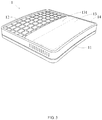
- FIG. 1 is a structural schematic diagram of an air purification apparatus according to some embodiments.
- the air purification apparatus is applied to a vehicle, and includes: a main body 11 and a solar module 12, wherein the solar module 12 covers at least a portion of the main body 11 and connects to the main body 11, for providing power to the main body 11.
- Providing power for the work of the main body 11 by the solar module 12 saves vehicle power source, and reduces connection lines, thereby improving the overall aesthetics of the air purification apparatus 1 and the inside of the vehicle.
- the main body 11 further includes a purification module 112, an air inlet module 111 and an air outlet module 113.
- An air inlet passage 1112 of the air inlet module 111 connects the purification module 112 and the outside of the vehicle, to inhale air from the outside of the vehicle and purify the inhaled air.
- An air outlet passage 1132 of the air outlet module 113 is able to connect the inside and the outside of the vehicle, to discharge the air from the vehicle.
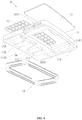
- the main body 11 is assembled on a sunroof of the vehicle, and includes a first passage 14 connected with the sunroof of the vehicle (See FIG. 2 ).
- the air purification apparatus 1 further includes a cover plate 13 that is slidably assembled with the main body 11, and the first passage 14 can be opened or closed by the sliding of the cover plate 13 along the main body 11.
- the purification module 112 of the main body 11 may inhale the air outside the vehicle, purify the inhaled air, and discharge the exhaust air from the vehicle, thereby improving the purification effect.
- the air purification apparatus 1 is installed outside corresponding to the sunroof of the vehicle, the first passage 14 of the main body 11 is connected with the sunroof, and the switch of the first passage 14 is controlled by the sliding of the cover plate 13, such that the purification effect is enhanced in virtue of the airflow advantage when the first passage 14 is closed, and the first passage 14 is connected with the sunroof when the first passage 14 is opened, so as to use the sunroof when the outside air of the vehicle is good.
- the present disclosure provides improvement on the setting of the air inlet module 111 and the air outlet module 113 that influence the air flow:
- the main body 11 of the air purification apparatus 1 may include a first side surface 114 and a second side surface 115 disposed opposite to each other.
- the first side surface 114 is provided with an air inlet 1111 connected with the air inlet passage 1112
- the second side surface 115 is provided with an air outlet 1131 connected with the air outlet passage 1132.
- the air inlet 1111 and the air outlet 1131 are disposed on opposite sides of the main body 11, thereby avoiding structural interference between the air inlet passage 1112 and the air outlet passage 1132, and simplifying the structures of the air inlet module 111 and the air outlet module 113, such that the flow efficiency and purification effect of the air are further enhanced.
- the air inlet 1111 and the air outlet 1131 may be disposed on other sides of the main body 11, which can be determined by considering the realization of effects of the air intake and air outlet, and to which the disclosure is not limited.
- the position of the air inlet 1111 corresponds to that of the air outlet 1131, and the cross-sectional areas of them are the same.
- the air inlet 1111 and the air outlet 1131 are structurally symmetrical, thereby improving the aesthetics of the air purification apparatus 1, and on the other hand, the air inlet position of the air inlet 1111 and the air outlet position of the air outlet 1131 are symmetrical and have the same cross-sectional area, which increases the controllability of the air flow direction and the air flow rate.
- the air inlets 1111 may be distributed in an array on the first side surface 114
- the air outlets 1131 may be distributed in an array on the second side surface 115.
- the structure aesthetic of the air purification apparatus 1 is further raised by distributing in arrays of the air inlets 1111 and the air outlets 1131.
- the air purification apparatus 1 is further provided with a cover plate 13 that is slidably assembled with the main body 11, and the first passage 14 can be opened or closed by the sliding of the cover plate 13 along the main body 11.
- the structure and arrangement of the cover plate 13 described above may be exemplarily illustrated by the following embodiments.
- the cover area of the cover plate 13 is larger than or equal to the cross-sectional area of the first passage 14, such that the cover plate 13 may open or close the first passage 14 when the cover plate 13 slides along the body 11.
- the cover area of the cover plate 13 is equal to the cross-sectional area of the first passage 14, as shown in FIG. 2 , and when the cover plate 13 slides along the main body 11 to the first passage 14, the first passage 14 is just covered to be closed.
- the above structure reduces the space of the air purification apparatus 1 occupied by the cover plate 13 under the premise of ensuring the function of the cover plate 13.
- the cover area of the cover plate 13 is larger than the cross-sectional area of the first passage 14, as shown in FIG.
- the cover plate 13 slides to the first passage 14, not only the first passage 14 is covered, but also a remaining portion 131 of the cover plate 13 that is assembled with other structures of the main body 11 is formed.
- the assembly of the remaining portion 131 and the main body 11 may increase the installation stability of the cover plate 13, and reduce the assembly difficulty of the cover plate 13.
- the main body 11 may further include a slide rail (Not shown) which is disposed above the upper surface of the solar module 12.
- the first passage 14 of the main body 11 is disposed side by side with the solar module 12, and the cover plate 13 is slidably assembled with the slide rail, so as to cover at least a portion of at least one of the solar module 12 and the first passage 14.
- the slide rail is disposed above the upper surface of the solar module 12, and the space above the solar module 12 is used as the move space for the cover 13 when the cover 13 leaves the first passage 14, such that the structure of the air purification apparatus 1 is compact, which improves the space utilization rate.
- the cover plate 13 may include a light transmitting glass or other light transmitting materials, which may be determined by considering no influence on the operation of the solar module 12, and to which the disclosure does not limit.
- the air purification apparatus 1 may further include: a sealing element 15 surrounding the main body 11 and disposed between the sunroof of the vehicle and the main body 11, to form a sealing assembly between the main body 11 and the sunroof of the vehicle, so as to prevent impurity such as rainwater, sand and the like entering the inside of the vehicle through the gap between the main body 11 and the sunroof, wherein the sealing member 15 may be an elastic structure, to form an elastic assembly between the air purification apparatus 1 and the vehicle, thereby increasing the installation stability of the air purification apparatus 1 during running of the vehicle, and avoiding damage due to bumping of the vehicle.
- a sealing element 15 surrounding the main body 11 and disposed between the sunroof of the vehicle and the main body 11, to form a sealing assembly between the main body 11 and the sunroof of the vehicle, so as to prevent impurity such as rainwater, sand and the like entering the inside of the vehicle through the gap between the main body 11 and the sunroof
- the sealing member 15 may be an elastic
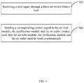
- FIG. 5 is a flow chart showing a 1 method of controlling the air purification apparatus above according to some embodiments.
- the air purification apparatus 1 described above may further include a fresh air switch 16 as shown in FIG. 4 , and the method may be implemented by the following steps:
- the user may start the air inlet module, the purification module and the air outlet module of the air purification apparatus through the fresh air switch, to make the air inlet module and the purification module and the air outlet module work synchronously, to inhale the outside air of the vehicle, purify it, then deliver the purified air into the vehicle, and discharge the exhaust air from the vehicle at the same time.
- the above method of controlling the air purification apparatus above is easily operated, which improves the air quality inside the vehicle and the convenience of the user.
- FIG. 6 is a structural block diagram of a control device according to some exemplary embodiments of the present disclosure.
- the above air purification apparatus 1 may further include a fresh air switch 16, and the control device 60 includes a receiving unit 61 and a sending unit 62, wherein the receiving unit 61 is configured to receive a start signal sent through the fresh air switch 16 from a user; and the sending unit 62 is configured to send a corresponding control signal to air inlet module, purification module and air outlet module, such that the air inlet module, the purification module and the air outlet module work synchronously.
- the air inlet module, the purification module and the air outlet module of the air purification apparatus may be started by the fresh air switch 16, to make that the air inlet module and the purification module and the air outlet module work synchronously, to inhale the outside air of the vehicle and purify it, then deliver the purified air into the vehicle, and discharge the exhaust air from the vehicle.
- the above device of controlling the air purification apparatus above is easily operated, which improves the air quality inside the vehicle and the convenience of the user.
- the present disclosure further provides a vehicle 2, as shown in FIG. 7 , and the vehicle 2 includes a vehicle body and the above-described air purification apparatus 1.
- a sunroof 21 is disposed on the vehicle body, and the air purification apparatus 1 is disposed outside the vehicle 2 and covers the sunroof 21.
- the above-described structural arrangement not only reduces the internal space of the vehicle 2 occupied by the air purification apparatus 1, but also improves the purification effect and the purification efficiency of the vehicle 2.
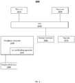
- FIG. 8 is a schematic diagram that illustrates a system 2000 wherein a peripheral controller 2040 comprises an air purification apparatus 2050 similar to the air purification apparatus described above.
- FIG. 8 illustrates but one application of the invention, that is the personal computer, but may be replaced by other applications such as a workstation, server, Internet driver or other fabric channels used as a link.
- peripheral controller 2040 is coupled to processor 2020 via a serial or parallel bus 2030.
- Processor 2020 is adapted to access data from peripheral controller 2040 via bus 2030.
- Memory 2010, and display controller 2060 may also be coupled to peripheral controller 2040 via bus 2030.
- Monitor 2070 may also be coupled to display controller 2060.
- Other peripheral devices 2080 such as a mouse, CD-ROM and video, may also be coupled to peripheral controller 2040.
- non-transitory computer readable storage medium including instructions, such as a memory including instructions.
- the instructions are executable by a processor of the above apparatus to perform the above method.
- the non-transitory computer readable storage medium may be a read only memory (ROM), a random access memory (RAM), a compact disc read only memory (CD-ROM), a magnetic tape, a floppy disk, an optical data storage device, and the like.
- a solar module connected with the main body for the air purification apparatus, to provide power source for the main body, reduces complicated power lines, and is energy-saving and environmentally friendly.
- the air inlet module and the air outlet module are also provided for the main body of the air purification apparatus, such that the purification module of the main body may inhale the air outside the vehicle, purify it, and discharge the exhaust air from the vehicle, thereby improving the purification effect.
- the air purification apparatus is installed outside the sunroof of the vehicle, the first passage of the main body is connected with the sunroof, and the switch of the first passage is controlled by the sliding of the cover plate. When the first passage is closed, the purification effect is enhanced in virtue of the airflow advantage, and when the first passage is opened, the first passage is connected to the sunroof, so as to easily use the sunroof when the outside air of the vehicle is good.
- first and second are used for descriptive purposes only and are not to be construed as indicating or implying a relative importance or implicitly indicating the number of technical features indicated.
- elements referred to as “first” and “second” may include one or more of the features either explicitly or implicitly.
- a plurality indicates two or more unless specifically defined otherwise.
- the terms “installed,” “connected,” “coupled,” “fixed” and the like shall be understood broadly, and may be either a fixed connection or a detachable connection, or integrated, unless otherwise explicitly defined. These terms can refer to mechanical or electrical connections, or both. Such connections can be direct connections or indirect connections through an intermediate medium. These terms can also refer to the internal connections or the interactions between elements. The specific meanings of the above terms in the present disclosure can be understood by those of ordinary skill in the art on a case-by-case basis.
- a first element being "on,” “over,” or “below” a second element may indicate direct contact between the first and second elements, without contact, or indirect through an intermediate medium, unless otherwise explicitly stated and defined.
- a first element being "above,” “over,” or “at an upper surface of' a second element may indicate that the first element is directly above the second element, or merely that the first element is at a level higher than the second element.
- the first element “below,” “underneath,” or “at a lower surface of' the second element may indicate that the first element is directly below the second element, or merely that the first element is at a level lower than the second feature.
- the first and second elements may or may not be in contact with each other.
- the terms “one embodiment,” “some embodiments,” “example,” “specific example,” or “some examples,” and the like may indicate a specific feature described in connection with the embodiment or example, a structure, a material or feature included in at least one embodiment or example.
- the schematic representation of the above terms is not necessarily directed to the same embodiment or example.
- control and/or interface software or app can be provided in a form of a non-transitory computer-readable storage medium having instructions stored thereon is further provided.
- the non-transitory computer-readable storage medium may be a Read-Only Memory (ROM), a Random-Access Memory (RAM), a Compact Disc Read-Only Memory (CD-ROM), a magnetic tape, a floppy disk, optical data storage equipment, a flash drive such as a USB drive or an SD card, and the like.
- Implementations of the subject matter and the operations described in this disclosure can be implemented in digital electronic circuitry, or in computer software, firmware, or hardware, including the structures disclosed herein and their structural equivalents, or in combinations of one or more of them. Implementations of the subject matter described in this disclosure can be implemented as one or more computer programs, i.e., one or more modules of computer program instructions, encoded on one or more computer storage medium for execution by, or to control the operation of, data processing apparatus.
- the program instructions can be encoded on an artificially-generated propagated signal, e.g., a machine-generated electrical, optical, or electromagnetic signal, that is generated to encode information for transmission to suitable receiver apparatus for execution by a data processing apparatus.
- an artificially-generated propagated signal e.g., a machine-generated electrical, optical, or electromagnetic signal
- a computer storage medium can be, or be included in, a computer-readable storage device, a computer-readable storage substrate, a random or serial access memory array or device, or a combination of one or more of them.
- a computer storage medium is not a propagated signal
- a computer storage medium can be a source or destination of computer program instructions encoded in an artificially-generated propagated signal.
- the computer storage medium can also be, or be included in, one or more separate components or media (e.g., multiple CDs, disks, drives, or other storage devices). Accordingly, the computer storage medium may be tangible.
- the operations described in this disclosure can be implemented as operations performed by a data processing apparatus on data stored on one or more computer-readable storage devices or received from other sources.
- the devices in this disclosure can include special purpose logic circuitry, e.g., an FPGA (field-programmable gate array), or an ASIC (application-specific integrated circuit).
- the device can also include, in addition to hardware, code that creates an execution environment for the computer program in question, e.g., code that constitutes processor firmware, a protocol stack, a database management system, an operating system, a cross-platform runtime environment, a virtual machine, or a combination of one or more of them.
- the devices and execution environment can realize various different computing model infrastructures, such as web services, distributed computing, and grid computing infrastructures.
- the devices can be controlled remotely through the Internet, on a smart phone, a tablet computer or other types of computers, with a web-based graphic user interface (GUI).
- GUI graphic user interface
- a computer program (also known as a program, software, software application, app, script, or code) can be written in any form of programming language, including compiled or interpreted languages, declarative or procedural languages, and it can be deployed in any form, including as a stand-alone program or as a module, component, subroutine, object, or other unit suitable for use in a computing environment.
- a computer program may, but need not, correspond to a file in a file system.
- a program can be stored in a portion of a file that holds other programs or data (e.g., one or more scripts stored in a markup language document), in a single file dedicated to the program in question, or in multiple coordinated files (e.g., files that store one or more modules, sub-programs, or portions of code).
- a computer program can be deployed to be executed on one computer or on multiple computers that are located at one site or distributed across multiple sites and interconnected by a communication network.
- the processes and logic flows described in this disclosure can be performed by one or more programmable processors executing one or more computer programs to perform actions by operating on input data and generating output.
- the processes and logic flows can also be performed by, and apparatus can also be implemented as, special purpose logic circuitry, e.g., an FPGA, or an ASIC.
- processors suitable for the execution of a computer program include, by way of example, both general and special purpose microprocessors, and any one or more processors of any kind of digital computer.
- a processor will receive instructions and data from a read-only memory, or a random-access memory, or both.
- Elements of a computer can include a processor configured to perform actions in accordance with instructions and one or more memory devices for storing instructions and data.
- a computer will also include, or be operatively coupled to receive data from or transfer data to, or both, one or more mass storage devices for storing data, e.g., magnetic, magneto-optical disks, or optical disks.
- mass storage devices for storing data
- a computer need not have such devices.
- a computer can be embedded in another device, e.g., a mobile telephone, a personal digital assistant (PDA), a mobile audio or video player, a game console, a Global Positioning System (GPS) receiver, or a portable storage device (e.g., a universal serial bus (USB) flash drive), to name just a few.
- PDA personal digital assistant
- GPS Global Positioning System
- USB universal serial bus
- Devices suitable for storing computer program instructions and data include all forms of non-volatile memory, media and memory devices, including by way of example semiconductor memory devices, e.g., EPROM, EEPROM, and flash memory devices; magnetic disks, e.g., internal hard disks or removable disks; magneto-optical disks; and CD-ROM and DVD-ROM disks.
- semiconductor memory devices e.g., EPROM, EEPROM, and flash memory devices
- magnetic disks e.g., internal hard disks or removable disks
- magneto-optical disks e.g., CD-ROM and DVD-ROM disks.
- the processor and the memory can be supplemented by, or incorporated in, special purpose logic circuitry.
Landscapes
- Engineering & Computer Science (AREA)
- Mechanical Engineering (AREA)
- Physics & Mathematics (AREA)
- Thermal Sciences (AREA)
- Air-Conditioning For Vehicles (AREA)
Abstract
Description
- The present disclosure relates to the technical field of vehicle, and more particularly to an air purification apparatus, a method of controlling the air purification apparatus, a device of controlling the air purification apparatus and a vehicle using the air purification apparatus.
- Air quality inside a vehicle directly influences the health and mood of a passenger. In the related art, it is usually to dispose an air purification apparatus inside the vehicle to circulate and purify the air inside the vehicle, so as to improve the air quality inside the vehicle. However, it is difficult to achieve desired effect simply by circulating and purifying the air inside the vehicle. Moreover, the installation position and power source type of the air purification apparatus directly influence the purification effect. Therefore, how to improve the purification effect of the air purification apparatus in structure view has become a hot issue in current research.
- In order to overcome the problems existing in the related art, the present disclosure provides an air purification apparatus, a control method, a device and a vehicle to enhance the purification effect and overall aesthetics of the air purification apparatus.
- According to a first aspect of the present invention, an air purification apparatus is provided, which is applied to a vehicle, and includes: a main body and a solar module, wherein the solar module covers at least a portion of the main body and connects the main body, for providing power to the main body,
the main body is assembled on a sunroof of the vehicle, and includes a first passage connected with the sunroof of the vehicle, and the air purification apparatus further includes a cover plate that slidably assembled with the main body, the cover plate is capable of sliding along the main body to open or close the first passage, and
the main body further includes a purification module, an air inlet module and an air outlet module, an air inlet passage of the air inlet module is capable of connecting the purification module and outside of the vehicle to inhale air from the outside of the vehicle and purify it, and an air outlet passage of the air outlet module is capable of connecting the inside and the outside of the vehicle to discharge air inside the vehicle. - In some embodiments, the main body includes a first side surface and a second side surface disposed opposite to each other, the first side surface is provided with an air inlet connected with the air inlet passage, and the second side surface is provided with an air outlet connected with the air outlet passage.
- In some embodiments, a position of the air inlet corresponds to that of the air outlet, and a cross-sectional area of the air inlet is the same as that of the air outlet.
- In some embodiments, a plurality of air inlets are distributed in an array on the first side surface, and a plurality of air outlets are distributed in an array on the second side surface.
- In some embodiments, a cover area of the cover plate is larger than or equal to a cross-sectional area of the first passage, such that the cover plate is capable of opening or closing the first passage when the cover plate slides along the main body.
- In some embodiments, the main body further includes a rail disposed above an upper surface of the solar module, and the cover plate is slidably assembled with the rail, to cover at least a portion of at least one of the solar module and the first passage.
- In some embodiments, the cover plate includes a light transmitting glass.
- In some embodiments, the apparatus further includes a sealing element surrounding the main body and disposed between the sunroof of the vehicle and the main body.
- In some embodiments, the sealing element includes an elastic structure.
- According to a second aspect of the present invention, a method of controlling an air purification apparatus is provided, and includes:
- receiving a start signal through a fresh air switch from a user; and
- sending a corresponding control signal to an air inlet module, a purification module and an air outlet module, such that the air inlet module, the purification module and the air outlet module work synchronously.
- According to a third aspect of the present invention, a device for controlling an air purification apparatus is provided, and includes: an air inlet; an air outlet; an air inlet module; a purification module; an air outlet module;
a receiving unit, configured to receive a start signal through a fresh air switch from a user; and
a sending unit, configured to send a corresponding control signal to an air inlet module, a purification module and an air outlet module, such that the air inlet module, the purification module and the air outlet module work synchronously. - In some embodiments, a position of the air inlet corresponds to the position of the air outlet, and a cross-sectional area of the air inlet is the same as the cross-sectional area of the air outlet.
- According to a fourth aspect of the present invention, a computer readable storage medium is provided, on which computer instructions are stored, wherein, when the computer instructions are executed by a processor, the steps of the method above is realized.
- According to a fifth aspect of the present invention, a system is provided and comprises a processor; and a peripheral controller coupled to the processor, the processor adapted to access data from the peripheral controller, the peripheral controller comprising: an air purification apparatus, applied to a vehicle, comprising: a main body and a solar module, wherein the solar module covers at least a portion of the main body and connects the main body, for providing power to the main body,
- the main body is assembled on a sunroof of the vehicle, and comprises a first passage connected with the sunroof of the vehicle, and the air purification apparatus further comprises a cover plate that slidably assembled with the main body, the cover plate is capable of sliding along the main body to open or close the first passage, and
the main body further comprises a purification module, an air inlet module and an air outlet module, an air inlet passage of the air inlet module is capable of connecting the purification module and outside of the vehicle to inhale air from the outside of the vehicle and purify it, and an air outlet passage of the air outlet module is capable of connecting the inside and the outside of the vehicle to discharge air inside the vehicle. - In some embodiments, the main body further comprises a first side surface and a second side surface disposed opposite to each other, the first side surface is provided with an air inlet connected with the air inlet passage, and the second side surface is provided with an air outlet connected with the air outlet passage.
- In some embodiments, a position of the air inlet corresponds to the position of the air outlet, and a cross-sectional area of the air inlet is the same as the cross-sectional area of the air outlet.
- In some embodiments, a plurality of air inlets are distributed in an array on the first side surface, and a plurality of air outlets are distributed in an array on the second side surface.
- In some embodiments, a cover area of the cover plate is larger than or equal to a cross-sectional area of the first passage, such that the cover plate is capable of opening or closing the first passage when the cover plate slides along the main body.
- In some embodiments, the main body further comprises a rail disposed above an upper surface of the solar module, and the cover plate is slidably assembled with the rail, to cover at least a portion of at least one of the solar module and the first passage.
- According to a sixth aspect of the present invention, a vehicle is provided, which includes a vehicle body and the air purification apparatus above, wherein a sunroof is provided on the vehicle body, and the air purification apparatus is disposed outside the vehicle and covers the sunroof.
- The technical solutions provided by the embodiments of the present disclosure may include the following beneficial effects:
- The present disclosure provides a solar module connected with the main body for the air purification apparatus, to provide power source for the main body, which reduces complicated power lines, and is energy-saving and environmentally friendly. The air inlet module and the air outlet module are also provided for the main body of the air purification apparatus, such that the purification module of the main body may inhale the air outside the vehicle, purify it, and discharge the exhaust air from the vehicle, thereby improving the purification effect. In addition, the air purification apparatus is installed outside the sunroof of the vehicle, the first passage of the main body is connected with the sunroof, and the switch of the first passage is controlled by the sliding of the cover plate. When the first passage is closed, the purification effect is enhanced in virtue of the airflow advantage, and when the first passage is opened, the first passage is connected to the sunroof, so as to easily use the sunroof when the outside air of the vehicle is good.
- It should be understood that both the foregoing general description and the following detailed description are exemplary and explanatory only and are not restrictive of the disclosure.
- The accompanying drawings, which are incorporated in and constitute a part of the present disclosure, illustrate embodiments consistent with the disclosure, and together with the description serve to explain the principles of the disclosure.
-
FIG. 1 is a structural schematic diagram of an air purification apparatus according to some embodiments; -
FIG. 2 is a structural schematic diagram of an air purification apparatus according to some embodiments; -
FIG. 3 is a schematic structural of an air purification apparatus according to still some embodiments; -
FIG. 4 is a structural schematic diagram of an air purification apparatus according to further still some embodiments; -
FIG. 5 is a flow chart showing a method of controlling an air purification apparatus according to some embodiments; -
FIG. 6 is a structural block diagram of a device of controlling an air purification apparatus according to some embodiments; and -
FIG. 7 is a structural schematic diagram of a vehicle according to some embodiments. -
FIG. 8 is a schematic diagram of a system wherein a peripheral controller comprises an air purification apparatus and is coupled to a processor that is adapted to access data from the peripheral controller according to some embodiments. - Reference will now be made in detail to some embodiments, examples of which are illustrated in the accompanying drawings. The following description refers to the accompanying drawings in which the same numbers in different drawings represent the same or similar elements unless otherwise represented. The implementations set forth in the following description of some embodiments do not represent all implementations consistent with the present disclosure. Instead, they are merely examples of apparatuses and methods consistent with aspects related to the disclosure as recited in the appended claims.
- The inventors of the present disclosure have recognized that, in order to improve the air quality inside a vehicle, an air purification apparatus is usually installed on the seat or the front console of the vehicle, wherein the air purification apparatus is connected with the vehicle power source, and the air quality is improved by circulating and purifying the air inside the vehicle. First, the air purification apparatus in the related art circulates and purifies the air inside the vehicle, which easily causes accumulation of harmful substances, so it is difficult to achieve the desired air quality; second, the installation position of the air purification apparatus in the related art is limited by the internal structure of the vehicle. For example, when the air purification apparatus is installed on the vehicle seat, the air flow is easily blocked by the structure of the seat and the like, so the air flow effect and the purification quality are reduced. In addition, the air purification apparatus in the related art may need to be connected to the vehicle power source, which occupies the vehicle power resource and increases the complexity of the connecting circuit, and influences the overall aesthetics.
- In order to solve the above technical problems, various embodiments of the present disclosure improves the structure of the air purification apparatus, which is described as follows.
-
FIG. 1 is a structural schematic diagram of an air purification apparatus according to some embodiments. As shown inFIG. 1 , the air purification apparatus is applied to a vehicle, and includes: amain body 11 and asolar module 12, wherein thesolar module 12 covers at least a portion of themain body 11 and connects to themain body 11, for providing power to themain body 11. Providing power for the work of themain body 11 by thesolar module 12 saves vehicle power source, and reduces connection lines, thereby improving the overall aesthetics of theair purification apparatus 1 and the inside of the vehicle. - The
main body 11 further includes apurification module 112, anair inlet module 111 and anair outlet module 113. Anair inlet passage 1112 of theair inlet module 111 connects thepurification module 112 and the outside of the vehicle, to inhale air from the outside of the vehicle and purify the inhaled air. Anair outlet passage 1132 of theair outlet module 113 is able to connect the inside and the outside of the vehicle, to discharge the air from the vehicle. - The
main body 11 is assembled on a sunroof of the vehicle, and includes afirst passage 14 connected with the sunroof of the vehicle (SeeFIG. 2 ). Theair purification apparatus 1 further includes acover plate 13 that is slidably assembled with themain body 11, and thefirst passage 14 can be opened or closed by the sliding of thecover plate 13 along themain body 11. - By providing the
air inlet module 111 and theair outlet module 113 that connect with the outside of the vehicle for themain body 11 of theair purification apparatus 1, thepurification module 112 of themain body 11 may inhale the air outside the vehicle, purify the inhaled air, and discharge the exhaust air from the vehicle, thereby improving the purification effect. In addition, theair purification apparatus 1 is installed outside corresponding to the sunroof of the vehicle, thefirst passage 14 of themain body 11 is connected with the sunroof, and the switch of thefirst passage 14 is controlled by the sliding of thecover plate 13, such that the purification effect is enhanced in virtue of the airflow advantage when thefirst passage 14 is closed, and thefirst passage 14 is connected with the sunroof when thefirst passage 14 is opened, so as to use the sunroof when the outside air of the vehicle is good. - Since air flow has a direct influence on the purification effect of the
air purification apparatus 1, the present disclosure provides improvement on the setting of theair inlet module 111 and theair outlet module 113 that influence the air flow: - Specifically, the
main body 11 of theair purification apparatus 1 may include afirst side surface 114 and asecond side surface 115 disposed opposite to each other. Thefirst side surface 114 is provided with anair inlet 1111 connected with theair inlet passage 1112, and thesecond side surface 115 is provided with anair outlet 1131 connected with theair outlet passage 1132. Theair inlet 1111 and theair outlet 1131 are disposed on opposite sides of themain body 11, thereby avoiding structural interference between theair inlet passage 1112 and theair outlet passage 1132, and simplifying the structures of theair inlet module 111 and theair outlet module 113, such that the flow efficiency and purification effect of the air are further enhanced. Alternatively, theair inlet 1111 and theair outlet 1131 may be disposed on other sides of themain body 11, which can be determined by considering the realization of effects of the air intake and air outlet, and to which the disclosure is not limited. - In some embodiments, the position of the
air inlet 1111 corresponds to that of theair outlet 1131, and the cross-sectional areas of them are the same. By such arrangement, on the one hand, theair inlet 1111 and theair outlet 1131 are structurally symmetrical, thereby improving the aesthetics of theair purification apparatus 1, and on the other hand, the air inlet position of theair inlet 1111 and the air outlet position of theair outlet 1131 are symmetrical and have the same cross-sectional area, which increases the controllability of the air flow direction and the air flow rate. - In some embodiments, there may be a plurality of
air inlets 1111 and theair outlets 1131, and the external aesthetics of theair purification apparatus 1 is improved by the plurality ofsmall air inlets 1111 andair outlets 1131. In addition, theair inlets 1111 may be distributed in an array on thefirst side surface 114, and theair outlets 1131 may be distributed in an array on thesecond side surface 115. The structure aesthetic of theair purification apparatus 1 is further raised by distributing in arrays of theair inlets 1111 and theair outlets 1131. - Since the
main body 11 is assembled on thesunroof 21 of the vehicle 2 (SeeFIG. 7 ), and includes thefirst passage 14 connected with thesunroof 21 of thevehicle 2. In order to cooperate with the use of thesunroof 21 of thevehicle 2 and thefirst passage 14, theair purification apparatus 1 is further provided with acover plate 13 that is slidably assembled with themain body 11, and thefirst passage 14 can be opened or closed by the sliding of thecover plate 13 along themain body 11. The structure and arrangement of thecover plate 13 described above may be exemplarily illustrated by the following embodiments. - In some embodiments, the cover area of the
cover plate 13 is larger than or equal to the cross-sectional area of thefirst passage 14, such that thecover plate 13 may open or close thefirst passage 14 when thecover plate 13 slides along thebody 11. When the cover area of thecover plate 13 is equal to the cross-sectional area of thefirst passage 14, as shown inFIG. 2 , and when thecover plate 13 slides along themain body 11 to thefirst passage 14, thefirst passage 14 is just covered to be closed. The above structure reduces the space of theair purification apparatus 1 occupied by thecover plate 13 under the premise of ensuring the function of thecover plate 13. When the cover area of thecover plate 13 is larger than the cross-sectional area of thefirst passage 14, as shown inFIG. 3 , and when thecover plate 13 slides to thefirst passage 14, not only thefirst passage 14 is covered, but also a remainingportion 131 of thecover plate 13 that is assembled with other structures of themain body 11 is formed. The assembly of the remainingportion 131 and themain body 11 may increase the installation stability of thecover plate 13, and reduce the assembly difficulty of thecover plate 13. - In the above embodiment, the
main body 11 may further include a slide rail (Not shown) which is disposed above the upper surface of thesolar module 12. Thefirst passage 14 of themain body 11 is disposed side by side with thesolar module 12, and thecover plate 13 is slidably assembled with the slide rail, so as to cover at least a portion of at least one of thesolar module 12 and thefirst passage 14. The slide rail is disposed above the upper surface of thesolar module 12, and the space above thesolar module 12 is used as the move space for thecover 13 when thecover 13 leaves thefirst passage 14, such that the structure of theair purification apparatus 1 is compact, which improves the space utilization rate. It should be noted that thecover plate 13 may include a light transmitting glass or other light transmitting materials, which may be determined by considering no influence on the operation of thesolar module 12, and to which the disclosure does not limit. - In addition, as shown in
FIG. 4 , theair purification apparatus 1 may further include: a sealingelement 15 surrounding themain body 11 and disposed between the sunroof of the vehicle and themain body 11, to form a sealing assembly between themain body 11 and the sunroof of the vehicle, so as to prevent impurity such as rainwater, sand and the like entering the inside of the vehicle through the gap between themain body 11 and the sunroof, wherein the sealingmember 15 may be an elastic structure, to form an elastic assembly between theair purification apparatus 1 and the vehicle, thereby increasing the installation stability of theair purification apparatus 1 during running of the vehicle, and avoiding damage due to bumping of the vehicle. - The present disclosure further provides a method of controlling the air purification apparatus above, applied to the air purification apparatus.
FIG. 5 is a flow chart showing a 1 method of controlling the air purification apparatus above according to some embodiments. Theair purification apparatus 1 described above may further include afresh air switch 16 as shown inFIG. 4 , and the method may be implemented by the following steps: - in
step 501, receiving a start signal via thefresh air switch 16 from a user; and - in
step 502, sending a corresponding control signal to air inlet module, purification module and air outlet module, such that the air inlet module, the purification module and the air outlet module work synchronously. - The user may start the air inlet module, the purification module and the air outlet module of the air purification apparatus through the fresh air switch, to make the air inlet module and the purification module and the air outlet module work synchronously, to inhale the outside air of the vehicle, purify it, then deliver the purified air into the vehicle, and discharge the exhaust air from the vehicle at the same time. The above method of controlling the air purification apparatus above is easily operated, which improves the air quality inside the vehicle and the convenience of the user.
- The present disclosure further provides a device of controlling the air purification apparatus above.
FIG. 6 is a structural block diagram of a control device according to some exemplary embodiments of the present disclosure. As shown inFIG. 4 , the aboveair purification apparatus 1 may further include afresh air switch 16, and thecontrol device 60 includes a receivingunit 61 and a sendingunit 62, wherein
the receivingunit 61 is configured to receive a start signal sent through thefresh air switch 16 from a user; and
the sendingunit 62 is configured to send a corresponding control signal to air inlet module, purification module and air outlet module, such that the air inlet module, the purification module and the air outlet module work synchronously. - The air inlet module, the purification module and the air outlet module of the air purification apparatus may be started by the
fresh air switch 16, to make that the air inlet module and the purification module and the air outlet module work synchronously, to inhale the outside air of the vehicle and purify it, then deliver the purified air into the vehicle, and discharge the exhaust air from the vehicle. The above device of controlling the air purification apparatus above is easily operated, which improves the air quality inside the vehicle and the convenience of the user. - The present disclosure further provides a
vehicle 2, as shown inFIG. 7 , and thevehicle 2 includes a vehicle body and the above-describedair purification apparatus 1. Asunroof 21 is disposed on the vehicle body, and theair purification apparatus 1 is disposed outside thevehicle 2 and covers thesunroof 21. The above-described structural arrangement not only reduces the internal space of thevehicle 2 occupied by theair purification apparatus 1, but also improves the purification effect and the purification efficiency of thevehicle 2. -
FIG. 8 is a schematic diagram that illustrates asystem 2000 wherein aperipheral controller 2040 comprises anair purification apparatus 2050 similar to the air purification apparatus described above.FIG. 8 illustrates but one application of the invention, that is the personal computer, but may be replaced by other applications such as a workstation, server, Internet driver or other fabric channels used as a link. InFIG. 8 ,peripheral controller 2040 is coupled toprocessor 2020 via a serial or parallel bus 2030.Processor 2020 is adapted to access data fromperipheral controller 2040 via bus 2030.Memory 2010, anddisplay controller 2060, may also be coupled toperipheral controller 2040 via bus 2030.Monitor 2070 may also be coupled todisplay controller 2060. Otherperipheral devices 2080, such as a mouse, CD-ROM and video, may also be coupled toperipheral controller 2040. - In some exemplary embodiments, there is also provided a non-transitory computer readable storage medium including instructions, such as a memory including instructions. The instructions are executable by a processor of the above apparatus to perform the above method. For example, the non-transitory computer readable storage medium may be a read only memory (ROM), a random access memory (RAM), a compact disc read only memory (CD-ROM), a magnetic tape, a floppy disk, an optical data storage device, and the like.
- At least some of the embodiments of the present disclosure can have one or more of the following advantages: a solar module connected with the main body for the air purification apparatus, to provide power source for the main body, reduces complicated power lines, and is energy-saving and environmentally friendly. The air inlet module and the air outlet module are also provided for the main body of the air purification apparatus, such that the purification module of the main body may inhale the air outside the vehicle, purify it, and discharge the exhaust air from the vehicle, thereby improving the purification effect. In addition, the air purification apparatus is installed outside the sunroof of the vehicle, the first passage of the main body is connected with the sunroof, and the switch of the first passage is controlled by the sliding of the cover plate. When the first passage is closed, the purification effect is enhanced in virtue of the airflow advantage, and when the first passage is opened, the first passage is connected to the sunroof, so as to easily use the sunroof when the outside air of the vehicle is good.
- In the present disclosure, it is to be understood that the terms "lower," "upper," "center," "longitudinal," "transverse," "length," "width," "thickness," "upper," "lower," "front," "back," "left," "right," "vertical," "horizontal," "top," "bottom," "inside," "outside," "clockwise," "counterclockwise," "axial," "radial," "circumferential," "column," "row," and other orientation or positional relationships are based on example orientations illustrated in the drawings, and are merely for the convenience of the description of some embodiments, rather than indicating or implying the device or component being constructed and operated in a particular orientation. Therefore, these terms are not to be construed as limiting the scope of the present disclosure.
- Moreover, the terms "first" and "second" are used for descriptive purposes only and are not to be construed as indicating or implying a relative importance or implicitly indicating the number of technical features indicated. Thus, elements referred to as "first" and "second" may include one or more of the features either explicitly or implicitly. In the description of the present disclosure, "a plurality" indicates two or more unless specifically defined otherwise.
- In the present disclosure, the terms "installed," "connected," "coupled," "fixed" and the like shall be understood broadly, and may be either a fixed connection or a detachable connection, or integrated, unless otherwise explicitly defined. These terms can refer to mechanical or electrical connections, or both. Such connections can be direct connections or indirect connections through an intermediate medium. These terms can also refer to the internal connections or the interactions between elements. The specific meanings of the above terms in the present disclosure can be understood by those of ordinary skill in the art on a case-by-case basis.
- In the present disclosure, a first element being "on," "over," or "below" a second element may indicate direct contact between the first and second elements, without contact, or indirect through an intermediate medium, unless otherwise explicitly stated and defined.
- Moreover, a first element being "above," "over," or "at an upper surface of' a second element may indicate that the first element is directly above the second element, or merely that the first element is at a level higher than the second element. The first element "below," "underneath," or "at a lower surface of' the second element may indicate that the first element is directly below the second element, or merely that the first element is at a level lower than the second feature. The first and second elements may or may not be in contact with each other.
- In the description of the present disclosure, the terms "one embodiment," "some embodiments," "example," "specific example," or "some examples," and the like may indicate a specific feature described in connection with the embodiment or example, a structure, a material or feature included in at least one embodiment or example. In the present disclosure, the schematic representation of the above terms is not necessarily directed to the same embodiment or example.
- Moreover, the particular features, structures, materials, or characteristics described may be combined in a suitable manner in any one or more embodiments or examples. In addition, various embodiments or examples described in the specification, as well as features of various embodiments or examples, may be combined and reorganized.
- In some embodiments, the control and/or interface software or app can be provided in a form of a non-transitory computer-readable storage medium having instructions stored thereon is further provided. For example, the non-transitory computer-readable storage medium may be a Read-Only Memory (ROM), a Random-Access Memory (RAM), a Compact Disc Read-Only Memory (CD-ROM), a magnetic tape, a floppy disk, optical data storage equipment, a flash drive such as a USB drive or an SD card, and the like.
- Implementations of the subject matter and the operations described in this disclosure can be implemented in digital electronic circuitry, or in computer software, firmware, or hardware, including the structures disclosed herein and their structural equivalents, or in combinations of one or more of them. Implementations of the subject matter described in this disclosure can be implemented as one or more computer programs, i.e., one or more modules of computer program instructions, encoded on one or more computer storage medium for execution by, or to control the operation of, data processing apparatus.
- Alternatively, or in addition, the program instructions can be encoded on an artificially-generated propagated signal, e.g., a machine-generated electrical, optical, or electromagnetic signal, that is generated to encode information for transmission to suitable receiver apparatus for execution by a data processing apparatus. A computer storage medium can be, or be included in, a computer-readable storage device, a computer-readable storage substrate, a random or serial access memory array or device, or a combination of one or more of them.
- Moreover, while a computer storage medium is not a propagated signal, a computer storage medium can be a source or destination of computer program instructions encoded in an artificially-generated propagated signal. The computer storage medium can also be, or be included in, one or more separate components or media (e.g., multiple CDs, disks, drives, or other storage devices). Accordingly, the computer storage medium may be tangible.
- The operations described in this disclosure can be implemented as operations performed by a data processing apparatus on data stored on one or more computer-readable storage devices or received from other sources.
- The devices in this disclosure can include special purpose logic circuitry, e.g., an FPGA (field-programmable gate array), or an ASIC (application-specific integrated circuit). The device can also include, in addition to hardware, code that creates an execution environment for the computer program in question, e.g., code that constitutes processor firmware, a protocol stack, a database management system, an operating system, a cross-platform runtime environment, a virtual machine, or a combination of one or more of them. The devices and execution environment can realize various different computing model infrastructures, such as web services, distributed computing, and grid computing infrastructures. For example, the devices can be controlled remotely through the Internet, on a smart phone, a tablet computer or other types of computers, with a web-based graphic user interface (GUI).
- A computer program (also known as a program, software, software application, app, script, or code) can be written in any form of programming language, including compiled or interpreted languages, declarative or procedural languages, and it can be deployed in any form, including as a stand-alone program or as a module, component, subroutine, object, or other unit suitable for use in a computing environment. A computer program may, but need not, correspond to a file in a file system. A program can be stored in a portion of a file that holds other programs or data (e.g., one or more scripts stored in a markup language document), in a single file dedicated to the program in question, or in multiple coordinated files (e.g., files that store one or more modules, sub-programs, or portions of code). A computer program can be deployed to be executed on one computer or on multiple computers that are located at one site or distributed across multiple sites and interconnected by a communication network.
- The processes and logic flows described in this disclosure can be performed by one or more programmable processors executing one or more computer programs to perform actions by operating on input data and generating output. The processes and logic flows can also be performed by, and apparatus can also be implemented as, special purpose logic circuitry, e.g., an FPGA, or an ASIC.
- Processors suitable for the execution of a computer program include, by way of example, both general and special purpose microprocessors, and any one or more processors of any kind of digital computer. Generally, a processor will receive instructions and data from a read-only memory, or a random-access memory, or both. Elements of a computer can include a processor configured to perform actions in accordance with instructions and one or more memory devices for storing instructions and data.
- Generally, a computer will also include, or be operatively coupled to receive data from or transfer data to, or both, one or more mass storage devices for storing data, e.g., magnetic, magneto-optical disks, or optical disks. However, a computer need not have such devices. Moreover, a computer can be embedded in another device, e.g., a mobile telephone, a personal digital assistant (PDA), a mobile audio or video player, a game console, a Global Positioning System (GPS) receiver, or a portable storage device (e.g., a universal serial bus (USB) flash drive), to name just a few.
- Devices suitable for storing computer program instructions and data include all forms of non-volatile memory, media and memory devices, including by way of example semiconductor memory devices, e.g., EPROM, EEPROM, and flash memory devices; magnetic disks, e.g., internal hard disks or removable disks; magneto-optical disks; and CD-ROM and DVD-ROM disks. The processor and the memory can be supplemented by, or incorporated in, special purpose logic circuitry.
- While this specification contains many specific implementation details, these should not be construed as limitations on the scope of any claims, but rather as descriptions of features specific to particular implementations. Certain features that are described in this specification in the context of separate implementations can also be implemented in combination in a single implementation. Conversely, various features that are described in the context of a single implementation can also be implemented in multiple implementations separately or in any suitable subcombination.
- Moreover, although features may be described above as acting in certain combinations and even initially claimed as such, one or more features from a claimed combination can in some cases be excised from the combination, and the claimed combination may be directed to a subcombination or variation of a subcombination.
- Similarly, while operations are depicted in the drawings in a particular order, this should not be understood as requiring that such operations be performed in the particular order shown or in sequential order, or that all illustrated operations be performed, to achieve desirable results. In certain circumstances, multitasking and parallel processing may be advantageous. Moreover, the separation of various system components in the implementations described above should not be understood as requiring such separation in all implementations, and it should be understood that the described program components and systems can generally be integrated together in a single software product or packaged into multiple software products.
- Thus, particular implementations of the subject matter have been described. Other implementations are within the scope of the following claims. In some cases, the actions recited in the claims can be performed in a different order and still achieve desirable results. In addition, the processes depicted in the accompanying figures do not necessarily require the particular order shown, or sequential order, to achieve desirable results. In certain implementations, multitasking or parallel processing may be utilized.
- It is intended that the specification and embodiments be considered as examples only. Other embodiments of the disclosure will be apparent to those skilled in the art in view of the specification and drawings of the present disclosure. That is, although specific embodiments have been described above in detail, the description is merely for purposes of illustration. It should be appreciated, therefore, that many aspects described above are not intended as required or essential elements unless explicitly stated otherwise.
- Various modifications of, and equivalent acts corresponding to, the disclosed aspects of the example embodiments, in addition to those described above, can be made by a person of ordinary skill in the art, having the benefit of the present disclosure, without departing from the scope of the disclosure defined in the following claims, the scope of which is to be accorded the broadest interpretation so as to encompass such modifications and equivalent structures.
Claims (15)
- An air purification apparatus (1), applied to a vehicle (2), comprising: a main body (11) and a solar module (12), wherein the solar module (12) covers at least a portion of the main body (11) and connects the main body (11), for providing power to the main body (11),
the main body (11) is assembled on a sunroof of the vehicle (2), and comprises a first passage (14) connected with the sunroof of the vehicle (2), and the air purification apparatus (1) further comprises a cover plate (13) that slidably assembled with the main body (11), the cover plate (13) is capable of sliding along the main body (11) to open or close the first passage (14), and
the main body (11) further comprises a purification module (112), an air inlet module (111), and an air outlet module (113), an air inlet passage (1112) of the air inlet module (111) is capable of connecting the purification module (112) and outside of the vehicle (2) to inhale air from the outside of the vehicle (2) and purify it, and an air outlet passage (1132) of the air outlet module (113) is capable of connecting the inside and the outside of the vehicle (2) to discharge air inside the vehicle (2). - The air purification apparatus (1) according to claim 1, wherein the main body (11) further comprises a first side surface (114) and a second side surface (115) disposed opposite to each other, the first side surface (114) is provided with an air inlet (1111) connected with the air inlet passage (1112), and the second side surface (115) is provided with an air outlet (1131) connected with the air outlet passage (1132).
- The air purification apparatus (1) according to claim 2, wherein a position of the air inlet (1111) corresponds to the position of the air outlet (1131), and a cross-sectional area of the air inlet (1111) is the same as the cross-sectional area of the air outlet (1131).
- The air purification apparatus (1) according to claim 2 or 3, wherein a plurality of air inlets (1111) are distributed in an array on the first side surface (114), and a plurality of air outlets (1131) are distributed in an array on the second side surface (115).
- The air purification apparatus (1) according to any one of the preceding claims, wherein a cover area of the cover plate (13) is larger than or equal to a cross-sectional area of the first passage (14), such that the cover plate (13) is capable of opening or closing the first passage (14) when the cover plate (13) slides along the main body (11).
- The air purification apparatus (1) according to claim 5, wherein the main body (11) further comprises a rail disposed above an upper surface of the solar module (12), and the cover plate (13) is slidably assembled with the rail, to cover at least a portion of at least one of the solar module (12) and the first passage (14).
- The air purification apparatus (1) according to any one of the preceding claims, wherein the cover plate (13) comprises a light transmitting glass.
- The air purification apparatus (1) according to any one of the preceding claims, wherein the apparatus further comprises a sealing element (15) surrounding the main body (11) and disposed between the sunroof of the vehicle (2) and the main body (11).
- The air purification apparatus (1) according to claim 8, wherein the sealing element (15) comprises an elastic structure.
- A method for controlling the air purification apparatus (1) according to any one of the preceding claims, comprising:receiving (501) a start signal through a fresh air switch (16) from a user; andsending (502) a corresponding control signal to an air inlet module (111), a purification module (112) and an air outlet module (113), such that the air inlet module (111), the purification module (112) and the air outlet module (113) work synchronously.
- A control device for controlling an air purification apparatus (1), comprising:an air inlet (1111);an air outlet (1131);an air inlet module (111);a purification module (112);an air outlet module (113);a receiving unit (61), configured to receive a start signal through a fresh air switch (16) from a user; anda sending unit (62), configured to send a corresponding control signal to the air inlet module (111), the purification module (112) and the air outlet module (113), such that the air inlet module (111), the purification module (112) and the air outlet module (113) work synchronously.
- The device according to claim 11, wherein a position of the air inlet (1111) corresponds to the position of the air outlet (1131), and a cross-sectional area of the air inlet (1111) is the same as the cross-sectional area of the air outlet (1131).
- A program product (2010) having computer instructions thereon for execution by a processor (2020) to realize the method of claim 10.
- A system comprising:a processor (2020); anda peripheral controller (2040) coupled to the processor, the processor adapted to access data from the peripheral controller (2040, the peripheral controller (2040 comprising: an air purification apparatus (1), applied to a vehicle (2), comprising: a main body (11) and a solar module (12), wherein the solar module (12) covers at least a portion of the main body (11) and connects the main body (11), for providing power to the main body (11),the main body (11) is assembled on a sunroof of the vehicle (2), and comprises a first passage (14) connected with the sunroof of the vehicle (2), and the air purification apparatus (1) further comprises a cover plate (13) that slidably assembled with the main body (11), the cover plate (13) is capable of sliding along the main body (11) to open or close the first passage (14), andthe main body (11) further comprises a purification module (112), an air inlet module (111) and an air outlet module (113), an air inlet passage (1112) of the air inlet module (111) is capable of connecting the purification module (112) and outside of the vehicle (2) to inhale air from the outside of the vehicle (2) and purify it, and an air outlet passage (1132) of the air outlet module (113) is capable of connecting the inside and the outside of the vehicle (2) to discharge air inside the vehicle (2).
- A vehicle (2) comprising the air purification apparatus (1) according to any one of claims 1 to 9, and a vehicle body, wherein the sunroof is provided on the vehicle body, and the air purification apparatus (1) is disposed outside the vehicle (2) and covers the sunroof.
Applications Claiming Priority (1)
| Application Number | Priority Date | Filing Date | Title |
|---|---|---|---|
| CN201810399173.3A CN108638805A (en) | 2018-04-28 | 2018-04-28 | Air cleaning unit, control method, device and vehicle |
Publications (2)
| Publication Number | Publication Date |
|---|---|
| EP3560737A1 true EP3560737A1 (en) | 2019-10-30 |
| EP3560737B1 EP3560737B1 (en) | 2021-03-31 |
Family
ID=63748499
Family Applications (1)
| Application Number | Title | Priority Date | Filing Date |
|---|---|---|---|
| EP19169879.4A Active EP3560737B1 (en) | 2018-04-28 | 2019-04-17 | Air purification apparatus, method of controlling the apparatus, device of controlling the apparatus and vehicle using the same |
Country Status (3)
| Country | Link |
|---|---|
| US (1) | US11383586B2 (en) |
| EP (1) | EP3560737B1 (en) |
| CN (1) | CN108638805A (en) |
Families Citing this family (3)
| Publication number | Priority date | Publication date | Assignee | Title |
|---|---|---|---|---|
| CN110481282B (en) * | 2019-07-30 | 2024-02-20 | 宁波悦坤智能科技有限公司 | Fresh air purifying device |
| USD1057918S1 (en) | 2021-06-23 | 2025-01-14 | Sharkninja Operating Llc | Air purifier |
| USD1120265S1 (en) | 2023-07-25 | 2026-03-24 | Sharkninja Operating Llc | Air purifier |
Citations (6)
| Publication number | Priority date | Publication date | Assignee | Title |
|---|---|---|---|---|
| DE4222508C1 (en) * | 1992-07-09 | 1993-08-26 | Webasto-Schade Gmbh, 8031 Oberpfaffenhofen, De | Automobile sliding roof incorporating ventilation fan - uses space provided by frame around roof opening to house at least one solar-powered fan |
| JP2001301451A (en) * | 1999-03-19 | 2001-10-31 | Denso Corp | Vehicle air purifier |
| JP2007022354A (en) * | 2005-07-19 | 2007-02-01 | Toyota Auto Body Co Ltd | Vehicle ceiling structure |
| FR2903345A1 (en) * | 2006-07-07 | 2008-01-11 | Valeo Systemes Thermiques | DEVICE FOR PREVENTILATION, VENTILATION, HEATING AND / OR AIR CONDITIONING OF A VEHICLE HABITACLE UTILIZING A PULSER AND THERMOELECTRIC UNITS WITH PELTIER EFFECT |
| KR20150116800A (en) * | 2014-04-08 | 2015-10-16 | 주식회사 대창 | Air cleaning device for use in a vehicle and vehicle including the same |
| WO2017149442A1 (en) * | 2016-02-29 | 2017-09-08 | Dometic Sweden Ab | Positive pressure vent for a vehicle |
Family Cites Families (16)
| Publication number | Priority date | Publication date | Assignee | Title |
|---|---|---|---|---|
| US6425629B1 (en) * | 1995-12-14 | 2002-07-30 | Charles R. Chubb | Vehicle roof for controlling light exposure of the skin |
| JP3320980B2 (en) * | 1996-05-30 | 2002-09-03 | コベルコ建機株式会社 | Cab air conditioner |
| JP2006117043A (en) * | 2004-10-20 | 2006-05-11 | Sharp Corp | Car air purifier |
| JP5381947B2 (en) * | 2010-09-27 | 2014-01-08 | アイシン精機株式会社 | Sunshade for vehicle |
| US8940078B2 (en) * | 2012-09-24 | 2015-01-27 | Schneider Electric USA, Inc. | Air filter sensor and alarm |
| KR20150113630A (en) * | 2014-03-31 | 2015-10-08 | 주식회사 대창 | Blower for vehicles |
| CN203995571U (en) * | 2014-07-22 | 2014-12-10 | 苏州志佳电子科技有限公司 | A kind of solar vehicle-mounted air purifier |
| DE102015120500A1 (en) * | 2015-11-26 | 2017-06-01 | Dr. Schneider Kunststoffwerke Gmbh | An air cleaning system and method for controlling an air cleaning system |
| CN205468468U (en) * | 2016-02-03 | 2016-08-17 | 李同祥 | Automatic car of controlling energy -conserving safe air -purifying skylight of taking a breath |
| CA2924437C (en) * | 2016-03-18 | 2023-09-12 | Logisig Inc. | Electronic cabinet, and air inlet therefore |
| CN106080148A (en) * | 2016-07-28 | 2016-11-09 | 安庆师范大学 | A kind of skylight of ventilating |
| CN206344658U (en) * | 2016-12-23 | 2017-07-21 | 比亚迪股份有限公司 | A kind of air cleaning system and vehicle |
| CN107264224A (en) * | 2017-06-09 | 2017-10-20 | 方剑明 | A kind of multifunctional vehicle mounted air-conditioning |
| CN107662477A (en) * | 2017-10-12 | 2018-02-06 | 西安立乐行环保科技有限公司 | A kind of concealed air intake vent vehicle-mounted air purification device of riser and vehicle |
| CN207963030U (en) * | 2017-11-27 | 2018-10-12 | 广东松下环境系统有限公司 | Air interchanger |
| CN107914546B (en) * | 2017-12-08 | 2023-08-01 | 东莞理工学院 | A kind of solar energy device and automobile for heat dissipation and cooling of automobile |
-
2018
- 2018-04-28 CN CN201810399173.3A patent/CN108638805A/en active Pending
-
2019
- 2019-04-17 EP EP19169879.4A patent/EP3560737B1/en active Active
- 2019-04-22 US US16/390,293 patent/US11383586B2/en active Active
Patent Citations (6)
| Publication number | Priority date | Publication date | Assignee | Title |
|---|---|---|---|---|
| DE4222508C1 (en) * | 1992-07-09 | 1993-08-26 | Webasto-Schade Gmbh, 8031 Oberpfaffenhofen, De | Automobile sliding roof incorporating ventilation fan - uses space provided by frame around roof opening to house at least one solar-powered fan |
| JP2001301451A (en) * | 1999-03-19 | 2001-10-31 | Denso Corp | Vehicle air purifier |
| JP2007022354A (en) * | 2005-07-19 | 2007-02-01 | Toyota Auto Body Co Ltd | Vehicle ceiling structure |
| FR2903345A1 (en) * | 2006-07-07 | 2008-01-11 | Valeo Systemes Thermiques | DEVICE FOR PREVENTILATION, VENTILATION, HEATING AND / OR AIR CONDITIONING OF A VEHICLE HABITACLE UTILIZING A PULSER AND THERMOELECTRIC UNITS WITH PELTIER EFFECT |
| KR20150116800A (en) * | 2014-04-08 | 2015-10-16 | 주식회사 대창 | Air cleaning device for use in a vehicle and vehicle including the same |
| WO2017149442A1 (en) * | 2016-02-29 | 2017-09-08 | Dometic Sweden Ab | Positive pressure vent for a vehicle |
Also Published As
| Publication number | Publication date |
|---|---|
| EP3560737B1 (en) | 2021-03-31 |
| CN108638805A (en) | 2018-10-12 |
| US20190329631A1 (en) | 2019-10-31 |
| US11383586B2 (en) | 2022-07-12 |
Similar Documents
| Publication | Publication Date | Title |
|---|---|---|
| US11383586B2 (en) | Air purification apparatus, method of controlling the apparatus, device of controlling the apparatus and vehicle using the same | |
| US11626748B2 (en) | Electronic device and method for wired and wireless charging in electronic device | |
| DE202016008942U1 (en) | Wireless charger | |
| WO2021003059A1 (en) | Resource allocation management for co-channel co-existence in intelligent transport systems | |
| US20200007414A1 (en) | Multi-access edge computing (mec) service contract formation and workload execution | |
| CN114143744A (en) | Co-channel coexistence frame structure for intelligent transportation systems with asymmetric gap duration | |
| Brito | Trends in wireless communications towards 5G networks—The influence of e-health and IoT applications | |
| EP3073567A1 (en) | Antenna apparatus and electronic device with the same | |
| FR2963500B1 (en) | CONNECTION DEVICE COMPRISING A CONTROL UNIT, BATTERY BOX COMPRISING SUCH A CONNECTION DEVICE, AND METHOD FOR CONTROLLING SUCH A BATTERY BOX. | |
| CN108556740A (en) | Multi-screen shares device and method, computer-readable medium, mobile unit | |
| US9573477B2 (en) | Method and device for charging electric vehicle in power system | |
| GB2485696A (en) | Data storage | |
| US20150253819A1 (en) | Waterproof electronic device | |
| US8964386B2 (en) | Server system | |
| US20160156214A1 (en) | Method for charging control and an electronic device thereof | |
| CN106664576A (en) | Communication method, electronic device and storage medium | |
| US20170227244A1 (en) | Enhanced techniques for air curtain control | |
| US11234081B2 (en) | Vibration module, electronic device, and method of controlling electronic device | |
| KR20150128287A (en) | Electrical Device for Supporting Multi Frequency Bands and Method for the same | |
| EP3296810B1 (en) | Display device and electronic device having same | |
| CN208873044U (en) | Automotive diagnostic installation and automotive diagnostic system | |
| CN108734500A (en) | Information distribution method, device, equipment and storage medium | |
| CN116724672A (en) | Smart pod-based cooling loop with dry cooler for mobile data center cooling system | |
| CN113739388B (en) | Air purifier, control method thereof and storage medium | |
| KR20240006070A (en) | Apparatus and method for configuring a semi-static pattern for PUCCH carrier switching |
Legal Events
| Date | Code | Title | Description |
|---|---|---|---|
| PUAI | Public reference made under article 153(3) epc to a published international application that has entered the european phase |
Free format text: ORIGINAL CODE: 0009012 |
|
| STAA | Information on the status of an ep patent application or granted ep patent |
Free format text: STATUS: THE APPLICATION HAS BEEN PUBLISHED |
|
| AK | Designated contracting states |
Kind code of ref document: A1 Designated state(s): AL AT BE BG CH CY CZ DE DK EE ES FI FR GB GR HR HU IE IS IT LI LT LU LV MC MK MT NL NO PL PT RO RS SE SI SK SM TR |
|
| AX | Request for extension of the european patent |
Extension state: BA ME |
|
| STAA | Information on the status of an ep patent application or granted ep patent |
Free format text: STATUS: REQUEST FOR EXAMINATION WAS MADE |
|
| 17P | Request for examination filed |
Effective date: 20200430 |
|
| RBV | Designated contracting states (corrected) |
Designated state(s): AL AT BE BG CH CY CZ DE DK EE ES FI FR GB GR HR HU IE IS IT LI LT LU LV MC MK MT NL NO PL PT RO RS SE SI SK SM TR |
|
| GRAP | Despatch of communication of intention to grant a patent |
Free format text: ORIGINAL CODE: EPIDOSNIGR1 |
|
| STAA | Information on the status of an ep patent application or granted ep patent |
Free format text: STATUS: GRANT OF PATENT IS INTENDED |
|
| INTG | Intention to grant announced |
Effective date: 20201015 |
|
| GRAS | Grant fee paid |
Free format text: ORIGINAL CODE: EPIDOSNIGR3 |
|
| GRAA | (expected) grant |
Free format text: ORIGINAL CODE: 0009210 |
|
| STAA | Information on the status of an ep patent application or granted ep patent |
Free format text: STATUS: THE PATENT HAS BEEN GRANTED |
|
| AK | Designated contracting states |
Kind code of ref document: B1 Designated state(s): AL AT BE BG CH CY CZ DE DK EE ES FI FR GB GR HR HU IE IS IT LI LT LU LV MC MK MT NL NO PL PT RO RS SE SI SK SM TR |
|
| REG | Reference to a national code |
Ref country code: GB Ref legal event code: FG4D Ref country code: CH Ref legal event code: EP |
|
| REG | Reference to a national code |
Ref country code: DE Ref legal event code: R096 Ref document number: 602019003527 Country of ref document: DE Ref country code: AT Ref legal event code: REF Ref document number: 1376536 Country of ref document: AT Kind code of ref document: T Effective date: 20210415 |
|
| REG | Reference to a national code |
Ref country code: IE Ref legal event code: FG4D |
|
| REG | Reference to a national code |
Ref country code: LT Ref legal event code: MG9D |
|
| PG25 | Lapsed in a contracting state [announced via postgrant information from national office to epo] |
Ref country code: NO Free format text: LAPSE BECAUSE OF FAILURE TO SUBMIT A TRANSLATION OF THE DESCRIPTION OR TO PAY THE FEE WITHIN THE PRESCRIBED TIME-LIMIT Effective date: 20210630 Ref country code: BG Free format text: LAPSE BECAUSE OF FAILURE TO SUBMIT A TRANSLATION OF THE DESCRIPTION OR TO PAY THE FEE WITHIN THE PRESCRIBED TIME-LIMIT Effective date: 20210630 Ref country code: FI Free format text: LAPSE BECAUSE OF FAILURE TO SUBMIT A TRANSLATION OF THE DESCRIPTION OR TO PAY THE FEE WITHIN THE PRESCRIBED TIME-LIMIT Effective date: 20210331 Ref country code: HR Free format text: LAPSE BECAUSE OF FAILURE TO SUBMIT A TRANSLATION OF THE DESCRIPTION OR TO PAY THE FEE WITHIN THE PRESCRIBED TIME-LIMIT Effective date: 20210331 |
|
| PG25 | Lapsed in a contracting state [announced via postgrant information from national office to epo] |
Ref country code: RS Free format text: LAPSE BECAUSE OF FAILURE TO SUBMIT A TRANSLATION OF THE DESCRIPTION OR TO PAY THE FEE WITHIN THE PRESCRIBED TIME-LIMIT Effective date: 20210331 Ref country code: LV Free format text: LAPSE BECAUSE OF FAILURE TO SUBMIT A TRANSLATION OF THE DESCRIPTION OR TO PAY THE FEE WITHIN THE PRESCRIBED TIME-LIMIT Effective date: 20210331 Ref country code: SE Free format text: LAPSE BECAUSE OF FAILURE TO SUBMIT A TRANSLATION OF THE DESCRIPTION OR TO PAY THE FEE WITHIN THE PRESCRIBED TIME-LIMIT Effective date: 20210331 |
|
| REG | Reference to a national code |
Ref country code: NL Ref legal event code: MP Effective date: 20210331 |
|
| REG | Reference to a national code |
Ref country code: AT Ref legal event code: MK05 Ref document number: 1376536 Country of ref document: AT Kind code of ref document: T Effective date: 20210331 |
|
| PG25 | Lapsed in a contracting state [announced via postgrant information from national office to epo] |
Ref country code: NL Free format text: LAPSE BECAUSE OF FAILURE TO SUBMIT A TRANSLATION OF THE DESCRIPTION OR TO PAY THE FEE WITHIN THE PRESCRIBED TIME-LIMIT Effective date: 20210331 Ref country code: SM Free format text: LAPSE BECAUSE OF FAILURE TO SUBMIT A TRANSLATION OF THE DESCRIPTION OR TO PAY THE FEE WITHIN THE PRESCRIBED TIME-LIMIT Effective date: 20210331 Ref country code: AT Free format text: LAPSE BECAUSE OF FAILURE TO SUBMIT A TRANSLATION OF THE DESCRIPTION OR TO PAY THE FEE WITHIN THE PRESCRIBED TIME-LIMIT Effective date: 20210331 Ref country code: CZ Free format text: LAPSE BECAUSE OF FAILURE TO SUBMIT A TRANSLATION OF THE DESCRIPTION OR TO PAY THE FEE WITHIN THE PRESCRIBED TIME-LIMIT Effective date: 20210331 Ref country code: EE Free format text: LAPSE BECAUSE OF FAILURE TO SUBMIT A TRANSLATION OF THE DESCRIPTION OR TO PAY THE FEE WITHIN THE PRESCRIBED TIME-LIMIT Effective date: 20210331 Ref country code: LT Free format text: LAPSE BECAUSE OF FAILURE TO SUBMIT A TRANSLATION OF THE DESCRIPTION OR TO PAY THE FEE WITHIN THE PRESCRIBED TIME-LIMIT Effective date: 20210331 |
|
| PG25 | Lapsed in a contracting state [announced via postgrant information from national office to epo] |
Ref country code: IS Free format text: LAPSE BECAUSE OF FAILURE TO SUBMIT A TRANSLATION OF THE DESCRIPTION OR TO PAY THE FEE WITHIN THE PRESCRIBED TIME-LIMIT Effective date: 20210731 Ref country code: PL Free format text: LAPSE BECAUSE OF FAILURE TO SUBMIT A TRANSLATION OF THE DESCRIPTION OR TO PAY THE FEE WITHIN THE PRESCRIBED TIME-LIMIT Effective date: 20210331 Ref country code: RO Free format text: LAPSE BECAUSE OF FAILURE TO SUBMIT A TRANSLATION OF THE DESCRIPTION OR TO PAY THE FEE WITHIN THE PRESCRIBED TIME-LIMIT Effective date: 20210331 Ref country code: PT Free format text: LAPSE BECAUSE OF FAILURE TO SUBMIT A TRANSLATION OF THE DESCRIPTION OR TO PAY THE FEE WITHIN THE PRESCRIBED TIME-LIMIT Effective date: 20210802 Ref country code: SK Free format text: LAPSE BECAUSE OF FAILURE TO SUBMIT A TRANSLATION OF THE DESCRIPTION OR TO PAY THE FEE WITHIN THE PRESCRIBED TIME-LIMIT Effective date: 20210331 |
|
| PG25 | Lapsed in a contracting state [announced via postgrant information from national office to epo] |
Ref country code: LU Free format text: LAPSE BECAUSE OF NON-PAYMENT OF DUE FEES Effective date: 20210417 |
|
| REG | Reference to a national code |
Ref country code: DE Ref legal event code: R097 Ref document number: 602019003527 Country of ref document: DE |
|
| REG | Reference to a national code |
Ref country code: BE Ref legal event code: MM Effective date: 20210430 |
|
| PG25 | Lapsed in a contracting state [announced via postgrant information from national office to epo] |
Ref country code: ES Free format text: LAPSE BECAUSE OF FAILURE TO SUBMIT A TRANSLATION OF THE DESCRIPTION OR TO PAY THE FEE WITHIN THE PRESCRIBED TIME-LIMIT Effective date: 20210331 Ref country code: MC Free format text: LAPSE BECAUSE OF FAILURE TO SUBMIT A TRANSLATION OF THE DESCRIPTION OR TO PAY THE FEE WITHIN THE PRESCRIBED TIME-LIMIT Effective date: 20210331 Ref country code: AL Free format text: LAPSE BECAUSE OF FAILURE TO SUBMIT A TRANSLATION OF THE DESCRIPTION OR TO PAY THE FEE WITHIN THE PRESCRIBED TIME-LIMIT Effective date: 20210331 Ref country code: DK Free format text: LAPSE BECAUSE OF FAILURE TO SUBMIT A TRANSLATION OF THE DESCRIPTION OR TO PAY THE FEE WITHIN THE PRESCRIBED TIME-LIMIT Effective date: 20210331 |
|
| PLBE | No opposition filed within time limit |
Free format text: ORIGINAL CODE: 0009261 |
|
| STAA | Information on the status of an ep patent application or granted ep patent |
Free format text: STATUS: NO OPPOSITION FILED WITHIN TIME LIMIT |
|
| 26N | No opposition filed |
Effective date: 20220104 |
|
| PG25 | Lapsed in a contracting state [announced via postgrant information from national office to epo] |
Ref country code: IE Free format text: LAPSE BECAUSE OF NON-PAYMENT OF DUE FEES Effective date: 20210417 |
|
| PG25 | Lapsed in a contracting state [announced via postgrant information from national office to epo] |
Ref country code: IS Free format text: LAPSE BECAUSE OF FAILURE TO SUBMIT A TRANSLATION OF THE DESCRIPTION OR TO PAY THE FEE WITHIN THE PRESCRIBED TIME-LIMIT Effective date: 20210731 |
|
| PG25 | Lapsed in a contracting state [announced via postgrant information from national office to epo] |
Ref country code: IT Free format text: LAPSE BECAUSE OF FAILURE TO SUBMIT A TRANSLATION OF THE DESCRIPTION OR TO PAY THE FEE WITHIN THE PRESCRIBED TIME-LIMIT Effective date: 20210331 Ref country code: BE Free format text: LAPSE BECAUSE OF NON-PAYMENT OF DUE FEES Effective date: 20210430 |
|
| REG | Reference to a national code |
Ref country code: CH Ref legal event code: PL |
|
| PG25 | Lapsed in a contracting state [announced via postgrant information from national office to epo] |
Ref country code: LI Free format text: LAPSE BECAUSE OF NON-PAYMENT OF DUE FEES Effective date: 20220430 Ref country code: CH Free format text: LAPSE BECAUSE OF NON-PAYMENT OF DUE FEES Effective date: 20220430 |
|
| P01 | Opt-out of the competence of the unified patent court (upc) registered |
Effective date: 20230523 |
|
| PG25 | Lapsed in a contracting state [announced via postgrant information from national office to epo] |
Ref country code: CY Free format text: LAPSE BECAUSE OF FAILURE TO SUBMIT A TRANSLATION OF THE DESCRIPTION OR TO PAY THE FEE WITHIN THE PRESCRIBED TIME-LIMIT Effective date: 20210331 |
|
| PG25 | Lapsed in a contracting state [announced via postgrant information from national office to epo] |
Ref country code: HU Free format text: LAPSE BECAUSE OF FAILURE TO SUBMIT A TRANSLATION OF THE DESCRIPTION OR TO PAY THE FEE WITHIN THE PRESCRIBED TIME-LIMIT; INVALID AB INITIO Effective date: 20190417 Ref country code: GR Free format text: LAPSE BECAUSE OF FAILURE TO SUBMIT A TRANSLATION OF THE DESCRIPTION OR TO PAY THE FEE WITHIN THE PRESCRIBED TIME-LIMIT Effective date: 20210331 |
|
| PG25 | Lapsed in a contracting state [announced via postgrant information from national office to epo] |
Ref country code: MK Free format text: LAPSE BECAUSE OF FAILURE TO SUBMIT A TRANSLATION OF THE DESCRIPTION OR TO PAY THE FEE WITHIN THE PRESCRIBED TIME-LIMIT Effective date: 20210331 |
|
| PG25 | Lapsed in a contracting state [announced via postgrant information from national office to epo] |
Ref country code: TR Free format text: LAPSE BECAUSE OF FAILURE TO SUBMIT A TRANSLATION OF THE DESCRIPTION OR TO PAY THE FEE WITHIN THE PRESCRIBED TIME-LIMIT Effective date: 20210331 |
|
| REG | Reference to a national code |
Ref country code: DE Ref legal event code: R082 Ref document number: 602019003527 Country of ref document: DE Representative=s name: DEHNS GERMANY PARTNERSCHAFT MBB, DE |
|
| PG25 | Lapsed in a contracting state [announced via postgrant information from national office to epo] |
Ref country code: MT Free format text: LAPSE BECAUSE OF FAILURE TO SUBMIT A TRANSLATION OF THE DESCRIPTION OR TO PAY THE FEE WITHIN THE PRESCRIBED TIME-LIMIT Effective date: 20210331 |
|
| PGFP | Annual fee paid to national office [announced via postgrant information from national office to epo] |
Ref country code: DE Payment date: 20250422 Year of fee payment: 7 |
|
| PGFP | Annual fee paid to national office [announced via postgrant information from national office to epo] |
Ref country code: GB Payment date: 20260303 Year of fee payment: 8 |
|
| PGFP | Annual fee paid to national office [announced via postgrant information from national office to epo] |
Ref country code: FR Payment date: 20260223 Year of fee payment: 8 |